WO2022149608A1 - 電気回路遮断装置 - Google Patents
電気回路遮断装置 Download PDFInfo
- Publication number
- WO2022149608A1 WO2022149608A1 PCT/JP2022/000321 JP2022000321W WO2022149608A1 WO 2022149608 A1 WO2022149608 A1 WO 2022149608A1 JP 2022000321 W JP2022000321 W JP 2022000321W WO 2022149608 A1 WO2022149608 A1 WO 2022149608A1
- Authority
- WO
- WIPO (PCT)
- Prior art keywords
- igniter
- projectile
- electric circuit
- resin material
- modified resin
- Prior art date
- Legal status (The legal status is an assumption and is not a legal conclusion. Google has not performed a legal analysis and makes no representation as to the accuracy of the status listed.)
- Ceased
Links
Images


Classifications
-
- H—ELECTRICITY
- H01—ELECTRIC ELEMENTS
- H01H—ELECTRIC SWITCHES; RELAYS; SELECTORS; EMERGENCY PROTECTIVE DEVICES
- H01H39/00—Switching devices actuated by an explosion produced within the device and initiated by an electric current
- H01H39/006—Opening by severing a conductor
-
- H—ELECTRICITY
- H01—ELECTRIC ELEMENTS
- H01H—ELECTRIC SWITCHES; RELAYS; SELECTORS; EMERGENCY PROTECTIVE DEVICES
- H01H9/00—Details of switching devices, not covered by groups H01H1/00 - H01H7/00
- H01H9/30—Means for extinguishing or preventing arc between current-carrying parts
-
- H—ELECTRICITY
- H01—ELECTRIC ELEMENTS
- H01H—ELECTRIC SWITCHES; RELAYS; SELECTORS; EMERGENCY PROTECTIVE DEVICES
- H01H33/00—High-tension or heavy-current switches with arc-extinguishing or arc-preventing means
- H01H33/02—Details
- H01H33/04—Means for extinguishing or preventing arc between current-carrying parts
-
- H—ELECTRICITY
- H01—ELECTRIC ELEMENTS
- H01H—ELECTRIC SWITCHES; RELAYS; SELECTORS; EMERGENCY PROTECTIVE DEVICES
- H01H39/00—Switching devices actuated by an explosion produced within the device and initiated by an electric current
-
- H—ELECTRICITY
- H01—ELECTRIC ELEMENTS
- H01H—ELECTRIC SWITCHES; RELAYS; SELECTORS; EMERGENCY PROTECTIVE DEVICES
- H01H50/00—Details of electromagnetic relays
- H01H50/02—Bases; Casings; Covers
-
- H—ELECTRICITY
- H02—GENERATION; CONVERSION OR DISTRIBUTION OF ELECTRIC POWER
- H02H—EMERGENCY PROTECTIVE CIRCUIT ARRANGEMENTS
- H02H3/00—Emergency protective circuit arrangements for automatic disconnection directly responsive to an undesired change from normal electric working condition with or without subsequent reconnection ; integrated protection
- H02H3/08—Emergency protective circuit arrangements for automatic disconnection directly responsive to an undesired change from normal electric working condition with or without subsequent reconnection ; integrated protection responsive to excess current
-
- H—ELECTRICITY
- H01—ELECTRIC ELEMENTS
- H01H—ELECTRIC SWITCHES; RELAYS; SELECTORS; EMERGENCY PROTECTIVE DEVICES
- H01H39/00—Switching devices actuated by an explosion produced within the device and initiated by an electric current
- H01H2039/008—Switching devices actuated by an explosion produced within the device and initiated by an electric current using the switch for a battery cutoff
-
- H—ELECTRICITY
- H01—ELECTRIC ELEMENTS
- H01H—ELECTRIC SWITCHES; RELAYS; SELECTORS; EMERGENCY PROTECTIVE DEVICES
- H01H50/00—Details of electromagnetic relays
- H01H50/54—Contact arrangements
- H01H50/546—Contact arrangements for contactors having bridging contacts
-
- H—ELECTRICITY
- H01—ELECTRIC ELEMENTS
- H01H—ELECTRIC SWITCHES; RELAYS; SELECTORS; EMERGENCY PROTECTIVE DEVICES
- H01H9/00—Details of switching devices, not covered by groups H01H1/00 - H01H7/00
- H01H9/30—Means for extinguishing or preventing arc between current-carrying parts
- H01H9/302—Means for extinguishing or preventing arc between current-carrying parts wherein arc-extinguishing gas is evolved from stationary parts
-
- H—ELECTRICITY
- H01—ELECTRIC ELEMENTS
- H01H—ELECTRIC SWITCHES; RELAYS; SELECTORS; EMERGENCY PROTECTIVE DEVICES
- H01H9/00—Details of switching devices, not covered by groups H01H1/00 - H01H7/00
- H01H9/30—Means for extinguishing or preventing arc between current-carrying parts
- H01H9/34—Stationary parts for restricting or subdividing the arc, e.g. barrier plate
- H01H9/36—Metal parts
-
- H—ELECTRICITY
- H01—ELECTRIC ELEMENTS
- H01H—ELECTRIC SWITCHES; RELAYS; SELECTORS; EMERGENCY PROTECTIVE DEVICES
- H01H9/00—Details of switching devices, not covered by groups H01H1/00 - H01H7/00
- H01H9/52—Cooling of switch parts
Definitions
- the present invention relates to an electric circuit breaker.
- the electric circuit may be provided with a breaking device that urgently cuts off the continuity in the electric circuit by operating in the event of an abnormality in the equipment constituting the electric circuit or in the case of an abnormality in the system in which the electric circuit is mounted.
- a breaking device that urgently cuts off the continuity in the electric circuit by operating in the event of an abnormality in the equipment constituting the electric circuit or in the case of an abnormality in the system in which the electric circuit is mounted.
- an electric circuit cutoff device has been proposed in which a projectile is moved at high speed by energy applied from an igniter or the like to forcibly and physically cut a conductor piece forming a part of an electric circuit. (See, for example, Patent Documents 1, 2, etc.). Further, in recent years, the importance of an electric circuit breaker applied to an electric vehicle equipped with a high voltage power supply is increasing more and more.
- the technique of the present disclosure has been made in view of the above circumstances, the purpose of which is to provide an electric circuit breaker capable of quickly extinguishing an arc during operation and preventing a decrease in insulation resistance value. To do.
- the electric circuit breaker of the present disclosure is used.
- the igniter installed in the housing and A projectile formed in the housing and arranged in a unidirectionally extending containment space, the projectile being launched along the containment space by the energy received from the igniter.
- Placed coolant material and A modified resin material arranged in the accommodation space and denatured by heat accompanying the operation of the igniter, and To prepare for.
- the modified resin material may be arranged between the cut portion and the coolant material.
- the electrical circuit breaker comprises a piston portion in which the projectile receives energy from the operation of the igniter and moves along the accommodation space.
- the modified resin material may be arranged on the arc extinguishing region side of the piston portion before the operation of the igniter.
- the electric circuit cutoff device includes a rod portion in which the projectile extends from a surface of the piston portion on the arc-extinguishing region side to the side of the conductor piece to be cut.
- the modified resin material may be arranged between the piston portion and the excised portion and between the inner wall of the housing forming the accommodation space and the rod before the operation of the igniter. ..
- the modified resin material may be formed in a ring shape or an arc shape along the inner wall surface of the housing.
- the coolant material is formed of metal fibers, and the coolant material is formed of metal fibers.
- the modified resin material may be impregnated between the metal fibers forming the coolant material.
- the modified resin material may be a synthetic resin containing silicone.
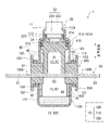
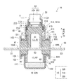
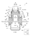
- FIG. 1 is a diagram illustrating an internal structure of an electric circuit breaking device (hereinafter, simply referred to as “breaking device”) according to an embodiment.
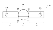
- FIG. 2 is a top view of the conductor piece according to the embodiment.
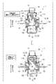
- FIG. 3 is a diagram illustrating an operating state of the breaking device according to the embodiment.
- FIG. 4 is a diagram illustrating the internal structure of the blocking device according to the first modification.
- FIG. 5 is a diagram illustrating the internal structure of the breaking device according to the modified example 2.
- FIG. 6 is a diagram illustrating the internal structure of the breaking device according to the modified example 3.
- FIG. 7 is an explanatory diagram of the coolant material and the modified resin material according to the modified example 3.
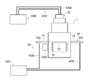
- FIG. 8 is a diagram showing an outline of a test device used for an electric circuit cutoff test.
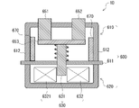
- FIG. 9 is a diagram illustrating the internal structure of the breaking device according to the second embodiment.
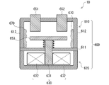
- FIG. 10 is a diagram showing a state after the operation of the breaking device according to the second embodiment
- FIG. 1 is a diagram illustrating an internal structure of an electric circuit breaking device (hereinafter, simply referred to as “breaking device”) 1 according to an embodiment.
- the cutoff device 1 cuts off an electric circuit in the event of an abnormality in an electric circuit included in, for example, an automobile, a household electric appliance, a solar power generation system, or a system including a battery (for example, a lithium ion battery) of the electric circuit. It is a device to prevent major damage in advance.
- the cross section along the height direction shown in FIG. 1 (the direction in which the accommodation space 13 described later extends) is referred to as a vertical cross section of the blocking device 1, and the cross section in the direction orthogonal to the height direction is blocked. It is called a cross section of the device 1.
- FIG. 1 shows a state before the operation of the breaking device 1.
- the blocking device 1 includes a housing 10 as an outer shell member, an igniter 20, a projectile 40, a conductor piece 50, a coolant material 60, a modified resin material 70, and the like.
- the housing 10 has a storage space 13 extending in the direction from the first end portion 11 on the upper end side to the second end portion 12 on the lower end side.
- the accommodation space 13 is a space formed in a straight line so that the projectile 40 can move, and extends along the vertical direction of the blocking device 1.
- the projectile 40 is housed in the housing space 13 formed inside the housing 10.
- the vertical direction of the breaking device 1 merely indicates the relative positional relationship of each element in the breaking device 1 for convenience of explanation of the embodiment.
- the housing 10 includes a housing body 100, a top holder 110, and a bottom container 120.
- a top holder 110 and a bottom container 120 are coupled to the housing body 100, whereby an integral housing 10 is formed.
- the housing body 100 has, for example, a substantially prismatic outer shape.
- the shape of the housing body 100 is not particularly limited.
- the housing body 100 is formed so that a hollow portion penetrates along the vertical direction, and this hollow portion forms a part of the accommodation space 13.
- the housing body 100 has an upper surface 101 to which the flange portion 111 of the top holder 110 is fixed and a lower surface 102 to which the flange portion 121 of the bottom container 120 is fixed.
- a cylindrical upper cylinder wall 103 is erected upward from the upper surface 101.
- the upper cylinder wall 103 has, for example, a square cylinder shape, but may have another shape.
- a tubular lower cylinder wall 104 is vertically provided downward from the lower surface 102.
- the lower cylinder wall 104 has, for example, a square cylinder shape, but may have another shape.
- the housing body 100 configured as described above can be formed of, for example, an insulating member such as a synthetic resin.
- the housing body 100 may be made of nylon, which is a kind of polyamide synthetic resin.
- the top holder 110 is, for example, a cylinder member having a stepped cylindrical shape, and has a hollow inside.
- the top holder 110 includes a small-diameter cylinder portion 112 located on the upper side (first end portion 11 side), a large-diameter cylinder portion 113 located on the lower side, a connection portion 114 connecting these, and a large-diameter cylinder portion 113. It is configured to include a flange portion 111 or the like extending from the lower end toward the outside.
- the small-diameter cylinder portion 112 and the large-diameter cylinder portion 113 are arranged coaxially, and the large-diameter cylinder portion 113 has a diameter one size larger than that of the small-diameter cylinder portion 112.
- the contour of the flange portion 111 of the top holder 110 has a substantially quadrangle so as to fit inside the upper cylinder wall 103 of the housing body 100.
- the flange portion 111 may be integrally fastened to the upper surface 101 of the housing body 100 using screws or the like while being arranged inside the upper cylinder wall 103, or may be fixed by rivets or the like. good.
- the top holder 110 may be connected to the housing body 100 with a sealant applied between the upper surface 101 of the housing body 100 and the lower surface of the flange portion 111 of the top holder 110. This makes it possible to improve the airtightness of the accommodation space 13 formed in the housing 10. Further, the airtightness of the accommodation space 13 may be improved by interposing an O-ring between the upper surface 101 of the housing body 100 and the flange portion 111 of the top holder 110 instead of the sealant or in combination with the sealant. good.
- the hollow portion formed inside the small diameter cylinder portion 112 in the top holder 110 functions as a storage space for accommodating a part of the igniter 20 as shown in FIG. Further, the hollow portion formed inside the large-diameter cylinder portion 113 in the top holder 110 communicates with the hollow portion of the housing body 100 located below, and forms a part of the accommodation space 13.
- the top holder 110 configured as described above can be formed of, for example, an appropriate metal member such as stainless steel or aluminum having excellent strength and durability. However, the material forming the top holder 110 is not particularly limited. Further, the above aspect is also an example of the shape of the top holder 110, and other shapes may be adopted.
- the bottom container 120 has a substantially bottomed tubular shape having a hollow inside, a side wall portion 122, a bottom wall portion 123 connected to the lower end of the side wall portion 122, a flange portion 121 connected to the upper end of the side wall portion 122, and the like. Is configured to include.
- the side wall portion 122 has, for example, a cylindrical shape, and the flange portion 121 extends outward from the upper end of the side wall portion 122.
- the contour of the flange portion 121 in the bottom container 120 has a substantially quadrangle so as to fit inside the lower cylinder wall 104 in the housing body 100.
- the flange portion 121 may be integrally fastened to the lower surface 102 of the housing body 100 using screws or the like while being arranged inside the lower cylinder wall 104, or may be fixed by rivets or the like.
- the bottom container 120 may be coupled to the housing body 100 with a sealant applied between the lower surface 102 of the housing body 100 and the upper surface of the flange portion 121 in the bottom container 120. This makes it possible to improve the airtightness of the accommodation space 13 formed in the housing 10. Further, the airtightness of the accommodation space 13 may be enhanced by interposing an O-ring between the lower surface 102 of the housing body 100 and the flange portion 121 of the bottom container 120 instead of the sealant or in combination with the sealant. good.
- the above aspect regarding the shape of the bottom container 120 is an example, and other shapes may be adopted. Further, the hollow portion formed inside the bottom container 120 communicates with the housing main body 100 located above and forms a part of the accommodation space 13.
- the bottom container 120 configured as described above can be formed of an appropriate metal member such as stainless steel or aluminum having excellent strength and durability.
- the material forming the bottom container 120 is not particularly limited.
- the bottom container 120 may have a multi-layer structure.
- the exterior portion facing the outside is formed of an appropriate metal member such as stainless steel or aluminum having excellent strength and durability, and the interior portion facing the accommodation space 13 side is insulated such as synthetic resin or the like. It may be formed by a member.
- the entire bottom container 120 may be formed of an insulating member.
- the housing 10 in the embodiment is configured to include the housing body 100, the top holder 110, and the bottom container 120 that are integrally assembled, and the direction from the first end portion 11 to the second end portion 12 inside the housing body 10.
- a housing space 13 extending to the housing space 13 is formed.
- the accommodating space 13 accommodates the igniter 20, the projectile 40, the cut portion 53 in the conductor piece 50, the coolant 60, the modified resin material 70, and the like, which will be described in detail below.
- the igniter 20 is an electric igniter including an igniter 21 containing an igniter and an igniter body 22 having a pair of conductive pins (not shown) connected to the igniter 21.
- the igniter body 22 is surrounded by, for example, an insulating resin. Further, the tip end side of the pair of conductive pins in the igniter main body 22 is exposed to the outside and is connected to the power supply when the cutoff device 1 is used.
- the igniter main body 22 includes a substantially columnar main body portion 221 housed inside the small diameter cylinder portion 112 in the top holder 110, and a connector portion 222 located above the main body portion 221.
- the igniter main body 22 is fixed to the small diameter cylinder portion 112, for example, by press-fitting the main body portion 221 into the inner peripheral surface of the small diameter cylinder portion 112. Further, in the axial middle portion of the main body portion 221, a constricted portion whose outer peripheral surface is recessed as compared with other parts is formed in an annular shape along the circumferential direction of the main body portion 221, and the O-ring 223 is fitted into this constricted portion. It has been.
- the O-ring 223 is formed of, for example, rubber (for example, silicone rubber) or synthetic resin, and functions to enhance the airtightness between the inner peripheral surface of the small-diameter cylinder portion 112 and the main body portion 221.
- the connector portion 222 of the igniter 20 is arranged so as to project outward through an opening 112A formed at the upper end of the small diameter cylinder portion 112.
- the connector portion 222 has, for example, a cylindrical shape that covers the side of the conductive pin, and is configured so that it can be connected to the connector on the power supply side.
- the ignition portion 21 of the igniter 20 is arranged so as to face the accommodation space 13 of the housing 10 (more specifically, the cavity portion formed inside the large-diameter cylinder portion 113).
- the ignition unit 21 is configured to contain, for example, an igniting agent in an igniter cup.
- the igniter is housed in the igniter cup in the ignition unit 21 in contact with a bridge wire (resistor) connected so as to connect the base ends of the pair of conductive pins.
- ZPP zirconium / potassium perchlorate
- ZWPP zirconium / tungsten / potassium perchlorate
- THPP titanium hydride / potassium perchlorate
- lead tricinate lead tricinate
- the bridge wire in the igniter 21 When operating the igniter 20, when the operating current for igniting the igniter is supplied from the power source to the conductive pin, the bridge wire in the igniter 21 generates heat, and as a result, the igniter in the igniter cup ignites and burns. And combustion gas is generated. Then, the pressure in the igniter cup rises with the combustion of the igniter in the igniter cup of the ignition unit 21, the cracking surface 21A of the igniter cup is cleaved, and the combustion gas is contained from the igniter cup in the accommodating space 13. Is released to. More specifically, the combustion gas from the igniter cup is discharged to the recessed portion 411 in the piston portion 41 described later of the projectile 40 arranged in the accommodation space 13.
- the projectile 40 is formed of, for example, an insulating member such as synthetic resin, and includes a piston portion 41 and a rod portion 42 connected to the piston portion 41.
- the piston portion 41 has a substantially cylindrical shape, and has an outer diameter substantially corresponding to the inner diameter of the large diameter cylinder portion 113 in the top holder 110.
- the diameter of the piston portion 41 may be slightly smaller than the inner diameter of the large diameter cylinder portion 113.
- the shape of the projectile 40 can be appropriately changed according to the shape of the housing 10 and the like.
- a recessed portion 411 having a cylindrical shape is formed on the upper surface of the piston portion 41, and the ignition portion 21 is received in the recessed portion 411.
- the bottom surface of the recessed portion 411 is formed as a pressure receiving surface 411A that receives energy received from the igniter 20 when the igniter 20 is operated.
- a constricted portion whose outer peripheral surface is recessed as compared with other parts is formed in an annular shape along the circumferential direction of the piston portion 41, and the O-ring 43 is fitted into this constricted portion. It has been.
- the O-ring 43 is formed of, for example, rubber (for example, silicone rubber) or synthetic resin, and functions to enhance the airtightness between the inner peripheral surface of the large-diameter cylinder portion 113 and the piston portion 41.
- the rod portion 42 of the projectile 40 is, for example, a rod-shaped member having an outer peripheral surface having a smaller diameter than the piston portion 41, and is integrally connected to the lower end side (arc extinguishing region side) of the piston portion 41 to form a conductor piece. It extends to the side to be excised.
- the lower end surface of the rod portion 42 is formed as a cut surface 421 for cutting the cut portion 53 from the conductor piece 50 when the blocking device 1 is activated.
- the rod portion 42 in the present embodiment has a substantially cylindrical shape, the shape is not particularly limited, and the shape and size of the cut portion 53 to be cut from the conductor piece 50 when the blocking device 1 is operated. May not change depending on.
- the rod portion 42 may have a pillar shape such as a cylinder or a prism.
- the region on the tip end side of the rod portion 42 of the projectile 40 including the cut surface 421 forms a part of the cavity portion (accommodation space 13) of the housing body 100.
- the diameter of the rod portion 42 is, for example, slightly smaller than the inner diameter of the inner peripheral surface of the housing body 100, and the outer peripheral surface of the rod portion 42 is guided along the inner peripheral surface when the projectile 40 is launched. Has been done.
- the projectile 40 configured as described above is described in detail later, but is launched by receiving energy from the igniter 20 when the igniter 20 is operated by the upper surface of the piston portion 41 including the pressure receiving surface 411A.
- the body 40 is launched from the initial position shown in FIG. 1 and moves at high speed toward the second end 12 side (downward) along the accommodation space 13.
- the piston portion 41 of the projectile 40 is housed inside the large-diameter cylinder portion 113 in the top holder 110, and has a shaft along the inner wall surface of the large-diameter cylinder portion 113. It can slide in the direction.
- the piston portion 41 of the projectile 40 has a substantially cylindrical shape, but the shape is not particularly limited.
- an appropriate shape and size may be adopted according to the shape and size of the inner wall surface of the large diameter cylinder portion 113.
- FIG. 2 is a top view of the conductor piece 50 according to the embodiment.
- the conductor piece 50 is a conductive metal body that constitutes a part of a component of the breaking device 1 and forms a part of the electric circuit when the breaking device 1 is attached to a predetermined electric circuit, and is a bus bar. Sometimes called (bus bar).
- the conductor piece 50 can be formed of, for example, a metal such as copper (Cu).
- the conductor piece 50 may be formed of a metal other than copper, or may be formed of an alloy of copper and another metal. Examples of the metal other than copper contained in the conductor piece 50 include manganese (Mn), nickel (Ni), platinum (Pt) and the like.
- the conductor piece 50 is formed as an elongated flat plate piece as a whole, and is located at the first connection end portion 51 and the second connection end portion 52 on both end sides and an intermediate portion thereof. Part 53 and the like are included.
- the first connection end 51 and the second connection end 52 of the conductor piece 50 are provided with connection holes 51A and 52A, respectively. These connection holes 51A and 52A are used for connecting to other conductors (for example, lead wires) in an electric circuit. In FIG. 1, the connection holes 51A and 52A in the conductor piece 50 are not shown.
- the cut portion 53 of the conductor piece 50 is forcibly and physically cut by the rod portion 42 of the projectile 40 when an abnormality such as an excessive current occurs in the electric circuit to which the breaking device 1 is applied.
- the conductor piece 50 can adopt various forms, and its shape is not particularly limited.
- the surfaces of the first connection end portion 51, the second connection end portion 52, and the cut portion 53 form the same surface, but the present invention is not limited to this.
- the cut portion 53 may be connected to the first connection end portion 51 and the second connection end portion 52 in an orthogonal or inclined posture.
- the planar shape of the cut portion 53 in the conductor piece 50 is not particularly limited.
- the shapes of the first connection end 51 and the second connection end 52 of the conductor piece 50 are not particularly limited.
- the notch 54 in the conductor piece 50 can be omitted as appropriate.
- a pair of conductor piece holding holes 105A and 105B are formed in the housing body 100 according to the embodiment.
- the pair of conductor piece holding holes 105A and 105B extend in the cross-sectional direction orthogonal to the vertical direction (axial direction) of the housing body 100. More specifically, the pair of conductor piece holding holes 105A and 105B extend in a straight line with the cavity portion (accommodation space 13) of the housing body 100 interposed therebetween.
- the conductor piece 50 configured as described above is held in the housing body 100 in a state of being inserted into the pair of conductor piece holding holes 105A and 105B formed in the housing body 100. In the example shown in FIG.
- the first connection end 51 of the conductor piece 50 is held in a state of being inserted into the conductor piece holding hole 105A, and the second connection end 52 is held in a state of being inserted into the conductor piece holding hole 105B. It is being held. Further, in this state, the excised portion 53 of the conductor piece 50 is positioned in the hollow portion (accommodation space 13) of the housing main body 100. As described above, the conductor piece 50 mounted on the housing body 100 is held in a posture orthogonal to the extending direction (axial direction) of the accommodation space 13 so that the cut portion 53 crosses the accommodation space 13. Orthogonal.
- the conductor piece 50 is installed so that the outer peripheral position L1 of the rod portion 42 substantially overlaps with the positions of the cuts 54 located at both ends of the cut portion 53.
- a gap is formed on the side of the excised portion 53.
- the projectile initial arrangement region R1 and the arc extinguishing region R2 are formed by the excised portion 53. They are not completely isolated, but communicate with each other. Of course, depending on the shape and size of the excised portion 53, the projectile initial placement region R1 and the arc extinguishing region R2 may be completely separated by the excised portion 53.
- the arc extinguishing region R2 of the accommodation space 13 is a region (space) for receiving the excised portion 53 excised by the rod portion 42 of the projectile 40 fired when the shutoff device 1 (igniter 20) is activated.
- a coolant 60 as an arc extinguishing material is arranged in the arc extinguishing region R2. The coolant 60 takes away the heat energy of the arc and the excised portion 53 generated when the projectile 40 excises the excised portion 53 of the conductor piece 50, and cools the arc to suppress the generation of an arc when the current is cut off. , It is a cooling material for extinguishing (disappearing) the generated arc.
- the arc extinguishing region R2 in the blocking device 1 is a space for receiving the cut portion 53 cut from the first connection end portion 51 and the second connection end portion 52 in the conductor piece 50 by the projectile 40, and at the same time, launches. It has significance as a space for effectively extinguishing the arc generated when the body 40 excises the excised portion 53. Then, in order to effectively extinguish the arc generated when the excised portion 53 is excised from the conductor piece 50, a coolant material 60 is arranged as an arc extinguishing material in the arc extinguishing region R2.
- the coolant material 60 is in a solid state. Further, as one aspect of the embodiment, the coolant material 60 is formed by a shape-retaining body.
- the shape-retaining body referred to here is, for example, a material that maintains a constant shape when no external force is applied and can maintain integrity (does not fall apart) even if deformation may occur when an external force is applied.
- a fiber body formed into a desired shape can be exemplified as a shape-retaining body.
- the coolant material 60 is formed of a metal fiber which is a shape-retaining body.
- examples of the metal fiber forming the coolant 60 include an embodiment containing at least one of steel wool and copper wool.
- the above aspect of the coolant material 60 is an example, and the present invention is not limited thereto.
- the coolant material 60 is, for example, formed into a substantially disk shape and is arranged at the bottom of the bottom container 120.
- the modified resin material 70 is arranged in the accommodation space 13 in the housing 10.
- the modified resin material 70 of the present embodiment is arranged in the arc extinguishing region R2, and when the igniter 20 is activated, the arc and the excised portion generated by the projectile 40 excising the excised portion 53 of the conductor piece 50. It is denatured by the heat of 53, and by consuming heat energy by this degeneration, it contributes to extinguishing (extinguishing) the arc.
- the modified resin material 70 functions as an arc extinguishing material in the same manner as the coolant material 60.
- the modification of the modified resin material 70 is mainly performed by the heat of the arc, but in addition to this, it is also affected by the heat generated when the excised portion 53 is excised and the heat of combustion of the igniter.
- the heat received from the ignition of the igniter to the completion of extinguishing the arc is referred to as the heat associated with the operation of the igniter 20.
- the modified resin material 70 of this embodiment is a synthetic resin containing silicone.
- the modified resin material is not limited to silicone, and other resins such as polyurethane, polyethylene, polypropylene, polyamide, and nitrile rubber may be used.
- the modified resin material 70 may be a material that is at least partially modified by heat, and may be made of a composite material containing a filler such as glass or ceramic.
- the modified resin material 70 is formed in a ring shape or an arc shape, and is provided along the inner wall of the side wall portion 122 from the upper surface of the coolant material 60 to the upper end of the bottom container 120.
- the modified resin material 70 is not limited to a solid member formed in a predetermined shape, but is used by applying a gel-like material or a highly viscous liquid material to the wall surface in the accommodation space 13 as shown in FIG. But it may be. Further, the modified resin material 70 may be one that is fixed to the wall surface by applying a synthetic resin melted with an organic solvent such as toluene to the wall surface in the accommodation space 13 and then volatilizing the organic solvent.
- FIG. 1 shows a state before the operation of the breaking device 1 (hereinafter, also referred to as “initial state before operation”).
- the piston portion 41 is positioned on the first end portion 11 side (upper end side) in the accommodation space 13, and the cut surface 421 formed at the lower end of the rod portion 42. Is set at the initial position positioned on the upper surface of the cut portion 53 in the conductor piece 50.
- the cutoff device 1 includes an abnormality detection sensor (not shown) for detecting an abnormal state of a device (vehicle, power generation equipment, power storage equipment, etc.) to which a cutoff electric circuit is connected, and an igniter 20. It also has a control unit (not shown) that controls the operation of the.
- the abnormality detection sensor may be able to detect an abnormal state based on the voltage and the temperature of the conductor piece 50 in addition to the current flowing through the conductor piece 50.
- the abnormality detection sensor is, for example, an impact sensor, a temperature sensor, an acceleration sensor, a vibration sensor, etc., and detects an abnormal state such as an accident or a fire based on the impact, temperature, acceleration, and vibration in a device such as a vehicle. May be good.
- the control unit of the shutoff device 1 is, for example, a computer capable of exerting a predetermined function by executing a predetermined control program. A predetermined function by the control unit can also be realized by the corresponding hardware. Then, when an excessive current flows through the conductor piece 50 forming a part of the electric circuit to which the breaking device 1 is applied, the abnormal current is detected by the abnormality detection sensor.
- the abnormality information regarding the detected abnormal current is passed from the abnormality detection sensor to the control unit.
- the control unit receives electricity from an external power source (not shown) connected to the conductive pin of the igniter 20 based on the current value detected by the abnormality detection sensor, and operates the igniter 20.
- the abnormal current may be a current value exceeding a predetermined threshold value set for protection of a predetermined electric circuit.
- the above-mentioned abnormality detection sensor and control unit may not be included in the components of the blocking device 1, and may be included in a device other than the blocking device 1, for example. Further, the abnormality detection sensor and the control unit are not indispensable to the shutoff device 1.
- the control unit of the breaking device 1 operates the igniter 20. That is, as a result of supplying an operating current to the conductive pin of the igniter 20 from an external power source (not shown), the igniting agent in the ignition unit 21 ignites and burns, and combustion gas is generated. Then, the cleavage surface 21A is cleaved due to the increase in pressure in the ignition portion 21, and the combustion gas of the igniting agent is discharged from the inside of the ignition portion 21 into the accommodation space 13.
- the ignition portion 21 of the igniter 20 is received by the recessed portion 411 in the piston portion 41, and the cracking surface 21A of the ignition portion 21 is arranged to face the pressure receiving surface 411A of the recessed portion 411 in the projectile 40. ing. Therefore, the combustion gas from the ignition unit 21 is discharged to the recessed portion 411, and the pressure (combustion energy) of the combustion gas is transmitted to the upper surface of the piston portion 41 including the pressure receiving surface 411A. As a result, the projectile 40 moves downward in the accommodation space 13 along the extending direction (axial direction) of the accommodation space 13.
- FIG. 3 is a diagram illustrating an operating state of the breaking device 1 according to the embodiment.
- the upper part of FIG. 3 shows the situation during the operation of the breaking device 1, and the lower part of FIG. 3 shows the situation where the operation of the breaking device 1 is completed.
- the projectile 40 that received the pressure (combustion energy) of the combustion gas of the igniter was vigorously pushed downward, and as a result, it was formed on the lower end side of the rod portion 42.
- the cut surface 421 pushes off each boundary portion between the first connection end portion 51 and the second connection end portion 52 and the cut portion 53 in the conductor piece 50 by shearing. As a result, the excised portion 53 is excised from the conductor piece 50.
- the projectile 40 can freely determine the shape and dimensions of the projectile 40 as long as it can smoothly move along the extending direction (axial direction) of the accommodation space 13 when the igniter 20 is operated.
- the outer diameter of the piston portion 41 in the projectile 40 may be set to the same dimension as the inner diameter of the large diameter cylinder portion 113 in the top holder 110.
- the projectile 40 extends in the extending direction of the accommodation space 13 by a predetermined stroke until the lower end surface of the piston portion 41 abuts (collides) with the upper surface 101 of the housing body 100. Move downward along the axial direction). Then, in this state, the cut portion 53 cut from the conductor piece 50 by the rod portion 42 in the projectile 40 is received in the arc extinguishing region R2 in which the coolant material 60 and the modified resin material 70 are arranged. As a result, the first connection end 51 and the second connection end 52 located at both ends of the conductor piece 50 are electrically disconnected, and the predetermined electric circuit to which the break device 1 is applied is forcibly cut off. ..
- the coolant 60 is arranged in the arc extinguishing region R2. Therefore, the excised portion 53 received in the arc extinguishing region R2 can be rapidly cooled by the coolant material 60. As a result, even if an arc is generated on the cut surface of the conductor piece 50 in the cut portion 53 when the cut portion 53 is cut from the conductor piece 50 constituting a part of a predetermined electric circuit by the projectile 40. The generated arc can be extinguished quickly and effectively.
- a modified resin material 70 as an arc extinguishing material is arranged between the coolant material 60 in the arc extinguishing region R2 and the cut portion 53.
- the modified resin material 70 is made of a material that is easily decomposed or volatilized by heat as compared with other resin materials such as the housing 10 and the projectile 40, and the heat of the arc is effectively consumed by this modification. be able to. Further, in the modified resin material 70 of the present embodiment, a component such as silica generated by thermal decomposition exhibits a high resistance value, and the scattering of this component contributes to improving the insulating property after cutting.
- the part to be cut 53 can be cooled by the coolant material 60 and the modified resin material 70, and the generation of arcs can be effectively suppressed.
- the electric circuit can be quickly cut off. That is, by effectively suppressing the delay in extinguishing the arc generated when the electric circuit is cut off, it is possible to suppress the delay in the cutoff of the electric circuit.
- the evaporation of the cut conductor piece 50 can be suppressed, and the insulation resistance after cutting can be made sufficiently high. ..
- the cutoff device 1 it is possible to suitably suppress the generation of a large spark or flame or the generation of a large impact sound when the electric circuit is cut off. Further, it is possible to prevent the housing 10 and the like of the breaking device 1 from being damaged due to these.
- FIG. 4 is a diagram illustrating an internal structure of the breaking device 1A according to the first modification.
- the blocking device 1A of the present modification 1 has a configuration in which the modified resin material 71 is arranged in the projectile initial arrangement region R1 in addition to the configuration of the blocking device 1 shown in FIG. Since the other configurations are the same, the description thereof will be omitted again.
- the modified resin material 71 is arranged between the piston portion 41 and the excised portion 53 and between the inner wall of the top holder 110 and the rod portion 42 before the operation of the igniter 20.
- a part of the rod portion 42 side of the modified resin material 71 moves to the cut portion 53 side together with the rod portion 42 due to friction with the rod portion 42.
- it is crushed by the piston portion 41 and moves to the side to be cut 53 from the gap between the conductor piece 50 and the inner wall of the top holder 110.
- the rod portion 42 cuts the cut portion 53 and an arc is generated, the modified resin material 71 is denatured by the heat of the arc to take away the heat of the arc and cool it.
- the moment when the cut portion 53 is cut from the conductor piece 50 by the cut surface 421 of the rod portion 42 and immediately after that that is, the moment when the cut portion 53 is cut from the conductor piece 50. Therefore, even in the transition state until the cut portion 53 comes into contact with the coolant material 60 arranged in the arc extinguishing region R2, the cut portion 53 can be cooled by the modified resin material 71. As a result, it is possible to suitably suppress the generation of an arc on the cut surface of the cut portion 53 at the moment when the cut portion 53 is cut from the conductor piece 50 and in the transition state immediately after that.
- FIG. 5 is a diagram illustrating the internal structure of the breaking device 1B according to the modified example 2.
- the blocking device 1B of the present modification 2 has a configuration in which the modified resin material 70 is removed from the configuration of the blocking device 1A shown in FIG. Since the other configurations are the same, the description thereof will be omitted again. Even if the modified resin material 70 is removed in this way, the modified resin material 71 cools the cut portion 53, so that the generation of an arc can be suppressed.
- FIG. 6 is a diagram illustrating the internal structure of the blocking device 1C according to the modified example 3
- FIG. 7 is an explanatory diagram of the coolant material 61 and the modified resin material 74 according to the modified example 3.
- the breaking device 1C of the present modification 3 has a configuration in which the modified resin material in the arc extinguishing region R2 is impregnated with the coolant material 61 as compared with the configuration of the breaking device 1A shown in FIG. Since the other configurations are the same, the description thereof will be omitted again.
- the coolant material 61 provided in the arc extinguishing region R2 is formed in a bowl shape along the inner wall of the bottom container 120 by metal fibers such as steel wool.
- the upper part of FIG. 7 schematically shows a cross section of the coolant material 61 formed of metal fibers.
- a modified resin material that is liquid in the initial state and solidifies by the reaction of air, heat, ultraviolet rays, etc. is used, and the modified resin material is impregnated into the peripheral wall 61W of the coolant material 61 in the liquid state and then solidified.
- the modified resin material 74 is formed on the peripheral wall 61W portion of the coolant material 61.
- the modified resin material 74 cools the excised portion 53 after excision, so that the arc can be extinguished quickly and effectively. Can be done. If the modified resin material has viscosity even in a liquid state and is held in a predetermined position in a state of being impregnated with the coolant material 61, solidification of the modified resin material 74 is not essential.
- FIG. 8 is a diagram showing an outline of a test device used for an electric circuit cutoff test.
- Reference numeral 1000 is a power supply
- reference numeral 2000 is an insulation resistance tester
- reference numeral 3000 is an operating power supply.
- reference numeral 4000 is wiring for forming the electric circuit EC in cooperation with the conductor piece 50 in the breaking device 1.
- reference numeral 5000 is wiring for passing the operating current supplied from the operating power supply 3000 to the conductive pin in the igniter 20 of the breaking device 1.
- Table 1 shows a list of conditions and results of the electric circuit cutoff test. Test sample No. in the table. 1 to No. No.
- test sample No. 3 to No. No. 4 conducted a test on a blocking device 1A provided with a modified resin material 71 in the projectile initial arrangement region R1 as shown in FIG.
- each test sample is tested according to the above procedure, and between the first connection end portion 51 and the second connection end portion 52 when the cut portion 53 is cut from the conductor piece 50 by the projectile 40.
- the insulation resistance value was measured with a commercially available insulation resistance meter 2000 (MY40 manufactured by Yokogawa Electric Corporation).
- the current value flowing through the electric circuit EC by the power supply 1000 is set to 12 [kA]
- the potential difference generated between the two connection ends 52 was set to 900 [V].
- the breaking devices 1 and 1A provided with the modified resin material 70 both obtained the result that the insulation resistance value between the first connection end portion 51 and the cut portion 53 was sufficiently high. Further, the test sample No. 1 in which the test was conducted without arranging the modified resin material 71 in the projectile initial arrangement region R1. 1 to No. Compared with No. 2, the test sample No. 1 in which the modified resin material 71 was arranged in the projectile initial arrangement region R1. 3 to No. The result of No. 4 was that the insulation resistance value between the first connection end portion 51 and the excised portion 53 was further higher.
- FIG. 9 is a diagram illustrating an internal structure of the breaking device 1D according to the second embodiment.
- the cutoff device 1D cuts off an electric circuit in the event of an abnormality in an electric circuit included in, for example, an automobile, a household electric appliance, a solar power generation system, or a system including a battery (for example, a lithium ion battery) of the electric circuit. It is a device to prevent major damage in advance.
- the cross section along the height direction shown in FIG. 9 (the direction in which the accommodation space 13 described later extends) is referred to as a vertical cross section of the blocking device 1, and the cross section in the direction orthogonal to the vertical cross section is referred to as the blocking device. It is called a 1D cross section.
- FIG. 9 shows a state before the operation of the breaking device 1D.
- FIG. 10 is a diagram showing a state after the operation of the breaking device 1D according to the present embodiment.
- the blocking device 1D includes a housing 600 as an outer shell member, an actuator 630, fixed contacts 651, 652, movable contacts 653, a modified resin material 670, and the like.
- the housing 600 is a substantially rectangular cuboid, is divided into an upper housing 610 and a lower housing, and is provided with a partition plate portion 611 between the upper housing 610 and the lower housing.
- An actuator 630 is provided in the lower housing 620.
- the actuator 630 has a movable shaft 631 and a drive coil 632 that drives the movable shaft 631 up and down.
- the movable shaft 631 is provided so as to penetrate the partition plate portion 611, and the tip thereof is located in the internal space 613 in the upper housing 610.
- a movable contact 653 is provided at the upper end of the movable shaft 631, and the movable contact 653 is driven up and down by the actuator 630 together with the movable shaft 631.
- each of the fixed contacts 651 and 652 is provided inside the upper housing 610, and the other end is arranged outside the upper housing 610 and connected to another electric circuit.
- the movable contact 653 is normally connected between the fixed contacts 651 and 652. Then, when the actuator 630 receives a disconnection signal when the external system is abnormal, the movable shaft 631 is lowered and the movable contact 653 is separated from the fixed contacts 651 and 652 to cut off the electric circuit connected to the fixed contacts 651 and 652. .
- the modified resin material 670 is provided along the peripheral wall 612 in the upper housing 610.
- the modified resin material 670 is formed in a ring shape so as to surround the fixed contacts 651 and 652 and the movable contacts 653.
- the modified resin material 670 is arranged so as to surround the fixed contacts 651 and 652 and the movable contact 653, the modified resin material 670 is modified by the heat of the arc, and the modified resin material 670 is denatured by this modification to take heat energy. Quickly extinguish (disappear) the arc. In this way, the modified resin material 670 functions as an arc extinguishing material.
- the composition of the modified resin material 670 and the like are the same as those of the above-mentioned modified resin material 70.
- the arc generated between the fixed contacts 651 and 652 and the movable contact 653 is cooled by the modified resin material 670, and the arc is quickly and effectively effective. Can be extinguished.
- Breaking device 10 Housing 13: Containment space 20: Ignition 40: Projectile 50: Conductor piece 53: Cut part 60: Coolant material 70: Modified resin material
Landscapes
- Physics & Mathematics (AREA)
- Electromagnetism (AREA)
- Fuses (AREA)
- Gas-Insulated Switchgears (AREA)
- Arc-Extinguishing Devices That Are Switches (AREA)
Abstract
Description
ハウジングに設けられた点火器と、
前記ハウジング内に形成されると共に一方向に延在する収容空間に配置された発射体であって、前記点火器から受けるエネルギーにより前記収容空間に沿って発射される発射体と、
前記ハウジングに設けられると共に電気回路の一部を形成する導体片であって、その一部に前記点火器から受けるエネルギーによって移動する前記発射体によって切除される被切除部を有し、当該被切除部が前記収容空間を横切るように配置された導体片と、
前記収容空間のうち、前記点火器の作動前において前記被切除部を挟んで前記発射体とは反対側に位置し、前記発射体によって切除された前記被切除部を受けるための消弧領域に配置された、クーラント材と、
前記収容空間内に配置され、前記点火器の作動に伴う熱によって変性する変性樹脂材と、
を備える。
前記変性樹脂材が、前記点火器の作動前において、前記ピストン部よりも前記消弧領域側に配置されてもよい。
前記変性樹脂材が、前記点火器の作動前において、前記ピストン部と前記被切除部との間であって、前記収容空間を成す前記ハウジングの内壁と前記ロッドとの間に配置されてもよい。
前記変性樹脂材が、前記クーラント材を形成する前記金属繊維の間に含侵されてもよい。
以下に、図面を参照して本開示の実施形態に係る電気回路遮断装置について説明する。なお、実施形態における各構成及びそれらの組み合わせ等は、一例であって、本開示の主旨から逸脱しない範囲内で、適宜、構成の付加、省略、置換、及びその他の変更が可能である。本開示は、実施形態によって限定されることはなく、特許請求の範囲によってのみ限定される。
図1は、実施形態に係る電気回路遮断装置(以下、単に「遮断装置」という)1の内部構造を説明する図である。遮断装置1は、例えば、自動車や家庭電化製品、太陽光発電システム等に含まれる電気回路や、当該電気回路のバッテリー(例えば、リチウムイオンバッテリー)を含むシステムの異常時に、電気回路を遮断することで大きな被害を未然に防止するための装置である。本明細書においては、図1に示す高さ方向(後述する収容空間13が延在する方向)に沿った断面を遮断装置1の縦断面といい、高さ方向と直交する方向の断面を遮断装置1の横断面という。図1は、遮断装置1の作動前の状態を示している。
ハウジング10は、ハウジング本体100、トップホルダ110、ボトム容器120を含む。ハウジング本体100には、トップホルダ110およびボトム容器120が結合されており、これによって一体のハウジング10が形成されている。
次に、トップホルダ110について説明する。トップホルダ110は、例えば、段付き円筒形状を有するシリンダ部材であり、内側が空洞状になっている。トップホルダ110は、上側(第1端部11側)に位置する小径シリンダ部112と、下側に位置する大径シリンダ部113と、これらを接続する接続部114と、大径シリンダ部113の下端から外側に向かって延在するフランジ部111等を含んで構成されている。例えば、小径シリンダ部112および大径シリンダ部113は同軸に配置されており、大径シリンダ部113は小径シリンダ部112よりも直径が一回り大きい。
次に、ボトム容器120について説明する。ボトム容器120は、内部が空洞状の概略有底筒形状を有し、側壁部122、側壁部122の下端に接続される底壁部123、側壁部122の上端に接続されるフランジ部121等を含んで構成されている。側壁部122は、例えば円筒形状を有しており、フランジ部121は側壁部122における上端から外側に向かって延在している。ボトム容器120におけるフランジ部121の輪郭は、ハウジング本体100における下筒壁104の内側に収まるような概略四角形を有している。フランジ部121は、例えば、下筒壁104の内側に配置された状態で、ハウジング本体100における下面102にネジ等を用いて一体に締結されていても良いし、リベット等によって固定されていても良い。ここで、ハウジング本体100の下面102とボトム容器120におけるフランジ部121の上面との間にはシーラントが塗布された状態でボトム容器120がハウジング本体100に結合されても良い。これにより、ハウジング10内に形成される収容空間13の気密性を高めることができる。また、シーラントの代わりに、或いはシーラントと併用してハウジング本体100の下面102とボトム容器120のフランジ部121との間にOリングを介在させることによって収容空間13の気密性を高めるようにしても良い。
次に、点火器20について説明する。点火器20は、点火薬を含む点火部21と、点火部21に接続された一対の導電ピン(図示せず)を有する点火器本体22を備えた電気式点火器である。点火器本体22は、例えば、絶縁樹脂によって包囲されている。また、点火器本体22における一対の導電ピンの先端側は外部に露出しており、遮断装置1の使用時に電源と接続される。
次に、発射体40について説明する。発射体40は、例えば、合成樹脂等の絶縁部材によって形成されており、ピストン部41と、当該ピストン部41に接続されたロッド部42を含んでいる。ピストン部41は概略円柱形状を有し、トップホルダ110における大径シリンダ部113の内径と概ね対応する外径を有している。例えば、ピストン部41の直径は、大径シリンダ部113の内径に比べて僅かに小さくても良い。発射体40の形状はハウジング10の形状等に応じて適宜変更することができる。
次に、導体片50について説明する。図2は、実施形態に係る導体片50の上面図である。導体片50は、遮断装置1の構成要素の一部を構成すると共に、遮断装置1を所定の電気回路に取り付けたときに当該電気回路の一部を形成する導電性の金属体であり、バスバー(bus bar)と呼ばれる場合がある。導体片50は、例えば、銅(Cu)等の金属によって形成することができる。但し、導体片50は、銅以外の金属で形成されていても良いし、銅と他の金属との合金で形成されても良い。なお、導体片50に含まれる銅以外の金属としては、マンガン(Mn)、ニッケル(Ni)、白金(Pt)等が例示できる。
次に、ハウジング10における収容空間13に配置されるクーラント材60について説明する。ここで、図1に示すように、遮断装置1(点火器20)の作動前において、ハウジング本体100における一対の導体片保持孔105A,105Bに保持された状態の導体片50の被切除部53は、ハウジング10の収容空間13を横切るように横架されている。以下、ハウジング10における収容空間13のうち、導体片50の被切除部53を挟んで発射体40が配置されている方の領域(空間)を「発射体初期配置領域R1」と呼び、発射体40とは反対側に位置する領域(空間)を「消弧領域R2」と呼ぶ。なお、上記のように、収容空間13を横切るように配置された被切除部53の側方に隙間が形成されているため、発射体初期配置領域R1および消弧領域R2は被切除部53によって完全に隔離されているのではなく、双方は連通している。勿論、被切除部53の形状および大きさ次第では、発射体初期配置領域R1および消弧領域R2が被切除部53によって完全に隔離されていても良い。
次に、変性樹脂材70について説明する。変性樹脂材70は、ハウジング10における収容空間13内に配置される。本実施形態の変性樹脂材70は、消弧領域R2に配置され、点火器20が作動した際、発射体40が導体片50の被切除部53を切除することで生じたアークおよび被切除部53の熱によって変性し、この変性によって熱エネルギーを消費させることでアークの消弧(消滅)に寄与する。このように変性樹脂材70は、クーラント材60と同様に消弧材として機能する。なお、変性樹脂材70の変性は、主にアークの熱によって行われるが、この他、被切除部53が切除される際に生じる熱や点火薬の燃焼熱などの熱の影響も受け、これら点火薬の点火から消弧完了までに受ける熱を点火器20の作動に伴う熱と称する。
次に、遮断装置1を作動させて電気回路を遮断する際の動作内容について説明する。上記のように、図1は、遮断装置1の作動前の状態(以下、「作動前初期状態」ともいう)を示している。この作動前初期状態において、遮断装置1における発射体40は、ピストン部41が収容空間13における第1端部11側(上端側)に位置付けられると共にロッド部42の下端に形成された切除面421が、導体片50における被切除部53の上面に位置付けられた初期位置にセットされている。
実施形態に係る遮断装置1は、種々の変形例を採用することができる。例えば、収容空間13の消弧領域R2に配置されるクーラント材60の形状、位置、範囲等は適宜変更することができる。例えば、図4は、変形例1に係る遮断装置1Aの内部構造を説明する図である。本変形例1の遮断装置1Aは、図1に示した遮断装置1の構成に加えて、変性樹脂材71を発射体初期配置領域R1に配置した構成としている。なお、その他の構成は、同じであるため、再度の説明は省略する。
図5は、変形例2に係る遮断装置1Bの内部構造を説明する図である。本変形例2の遮断装置1Bは、図4に示した遮断装置1Aの構成から変性樹脂材70を除いた構成としている。なお、その他の構成は、同じであるため、再度の説明は省略する。このように変性樹脂材70を除いた構成としても、変性樹脂材71によって被切除部53を冷却するので、アークの発生を抑制することができる。
図6は、変形例3に係る遮断装置1Cの内部構造を説明する図、図7は、変形例3に係るクーラント材61及び変性樹脂材74の説明図である。本変形例3の遮断装置1Cは、図4に示した遮断装置1Aの構成と比べて、消弧領域R2内の変性樹脂材をクーラント材61に含侵させた構成としている。なお、その他の構成は、同じであるため、再度の説明は省略する。
次に、遮断装置1,1Aに対して行った電気回路遮断試験について説明する。図8は、電気回路遮断試験に用いた試験装置の概略を示す図である。符号1000は電源、符号2000は絶縁抵抗計、符号3000は作動用電源である。また、符号4000は、遮断装置1における導体片50と協働して電気回路ECを形成するための配線である。また、符号5000は、遮断装置1の点火器20における導電ピンに作動用電源3000から供給される作動用電流を流すための配線である。

表1は、電気回路遮断試験の条件および結果一覧を示す。表中の試験サンプルNo.1~No.2は、図1に示すように発射体初期配置領域R1に変性樹脂材71を備えていない遮断装置1について試験を行った。一方、試験サンプルNo.3~No.4は、図4に示すように発射体初期配置領域R1に変性樹脂材71を設けた遮断装置1Aについて試験を行った。
(手順1)図8に示すように、遮断装置1における導体片50の第1接続端部51および第2接続端部52をそれぞれ配線4000によって電源1000に接続し、遮断装置1における点火器20を配線5000によって作動用電源3000に接続する。
(手順2)電源1000からの電流を電気回路ECに流す。
(手順3)作動用電源3000をオンにし、遮断装置1における点火器20に作動用電流を通電することによって点火器20を作動させる。
(手順4)電源1000、作動用電源3000をオフにする。
図9は、第二実施形態に係る遮断装置1Dの内部構造を説明する図である。遮断装置1Dは、例えば、自動車や家庭電化製品、太陽光発電システム等に含まれる電気回路や、当該電気回路のバッテリー(例えば、リチウムイオンバッテリー)を含むシステムの異常時に、電気回路を遮断することで大きな被害を未然に防止するための装置である。本明細書においては、図9に示す高さ方向(後述する収容空間13が延在する方向)に沿った断面を遮断装置1の縦断面といい、縦断面に直交する方向の断面を遮断装置1Dの横断面という。図9は、遮断装置1Dの作動前の状態を示している。図10は、本実施形態に係る遮断装置1Dの作動後の状態を示す図である。
10 :ハウジング
13 :収容空間
20 :点火器
40 :発射体
50 :導体片
53 :被切除部
60 :クーラント材
70 :変性樹脂材
Claims (7)
- ハウジングに設けられた点火器と、
前記ハウジング内に形成されると共に一方向に延在する収容空間に配置された発射体であって、前記点火器から受けるエネルギーにより前記収容空間に沿って発射される発射体と、
前記ハウジングに設けられると共に電気回路の一部を形成する導体片であって、その一部に前記点火器から受けるエネルギーによって移動する前記発射体によって切除される被切除部を有し、当該被切除部が前記収容空間を横切るように配置された導体片と、
前記収容空間のうち、前記点火器の作動前において前記被切除部を挟んで前記発射体とは反対側に位置し、前記発射体によって切除された前記被切除部を受けるための消弧領域に配置された、クーラント材と、
前記収容空間内に配置され、前記点火器の作動に伴う熱によって変性する変性樹脂材と、
を備える、電気回路遮断装置。 - 前記変性樹脂材が、前記被切除部と前記クーラント材との間に配置されている請求項1に記載の電気回路遮断装置。
- 前記発射体が、前記点火器の作動によるエネルギーを受け、前記収容空間に沿って移動するピストン部を備え、
前記変性樹脂材が、前記点火器の作動前において、前記ピストン部よりも前記消弧領域側に配置されている請求項1又は2に記載の電気回路遮断装置。 - 前記発射体が、前記ピストン部の前記消弧領域側の面から前記導体片の前記被切除部側に延設されたロッド部を備え、
前記変性樹脂材が、前記点火器の作動前において、前記ピストン部と前記被切除部との間であって、前記収容空間を成す前記ハウジングの内壁と前記ロッド部との間に配置された請求項3に記載の電気回路遮断装置。 - 前記変性樹脂材が、前記ハウジングの内壁面に沿ってリング状又は円弧状に形成されている請求項1~4の何れか1項に記載の電気回路遮断装置。
- 前記クーラント材が、金属繊維によって形成され、
前記変性樹脂材が、前記クーラント材を形成する前記金属繊維の間に含侵されている請求項1~5の何れか1項に記載の電気回路遮断装置。 - 前記変性樹脂材が、シリコーンを含む合成樹脂である請求項1~6の何れか1項に記載の電気回路遮断装置。
Priority Applications (4)
| Application Number | Priority Date | Filing Date | Title |
|---|---|---|---|
| KR1020237026525A KR103007710B1 (ko) | 2021-01-08 | 2022-01-07 | 전기 회로 차단 장치 |
| US18/271,254 US12537153B2 (en) | 2021-01-08 | 2022-01-07 | Electrical circuit circuit-breaking device |
| EP22736776.0A EP4276875B1 (en) | 2021-01-08 | 2022-01-07 | Electric circuit breaker device |
| CN202280009272.0A CN116802763A (zh) | 2021-01-08 | 2022-01-07 | 电路断路装置 |
Applications Claiming Priority (2)
| Application Number | Priority Date | Filing Date | Title |
|---|---|---|---|
| JP2021002335A JP7558817B2 (ja) | 2021-01-08 | 2021-01-08 | 電気回路遮断装置 |
| JP2021-002335 | 2021-01-08 |
Publications (1)
| Publication Number | Publication Date |
|---|---|
| WO2022149608A1 true WO2022149608A1 (ja) | 2022-07-14 |
Family
ID=82357960
Family Applications (1)
| Application Number | Title | Priority Date | Filing Date |
|---|---|---|---|
| PCT/JP2022/000321 Ceased WO2022149608A1 (ja) | 2021-01-08 | 2022-01-07 | 電気回路遮断装置 |
Country Status (5)
| Country | Link |
|---|---|
| US (1) | US12537153B2 (ja) |
| EP (1) | EP4276875B1 (ja) |
| JP (1) | JP7558817B2 (ja) |
| CN (1) | CN116802763A (ja) |
| WO (1) | WO2022149608A1 (ja) |
Cited By (2)
| Publication number | Priority date | Publication date | Assignee | Title |
|---|---|---|---|---|
| WO2024135709A1 (ja) * | 2022-12-23 | 2024-06-27 | パナソニックIpマネジメント株式会社 | 遮断装置 |
| WO2024161861A1 (ja) * | 2023-02-03 | 2024-08-08 | パナソニックIpマネジメント株式会社 | 遮断装置 |
Families Citing this family (3)
| Publication number | Priority date | Publication date | Assignee | Title |
|---|---|---|---|---|
| WO2022011410A1 (de) * | 2020-07-15 | 2022-01-20 | Astotec Automotive Gmbh | Pyrotechnischer stromtrenner |
| JP2023143090A (ja) * | 2022-03-25 | 2023-10-06 | 株式会社ダイセル | 電気回路遮断装置 |
| JP2026055458A (ja) * | 2024-09-18 | 2026-03-31 | 株式会社ダイセル | 摺動構造体、電気回路遮断装置および摺動構造体の作動方法 |
Citations (5)
| Publication number | Priority date | Publication date | Assignee | Title |
|---|---|---|---|---|
| JP2009295419A (ja) * | 2008-06-05 | 2009-12-17 | Fuji Electric Fa Components & Systems Co Ltd | 消弧用樹脂加工品、及びそれを用いた回路遮断器 |
| JP2010102936A (ja) * | 2008-10-23 | 2010-05-06 | Tempearl Ind Co Ltd | 回路遮断器 |
| US8957335B2 (en) | 2010-08-27 | 2015-02-17 | Auto Kabel Managementgesellschaft Mbh | Electrical disconnecting device and method for the electrical isolation of connecting parts with the aid of a disconnecting device |
| WO2020093079A1 (de) | 2018-11-06 | 2020-05-14 | Hirtenberger Automotive Safety Gmbh & Co Kg | Pyrotechnischer stromtrenner |
| JP2020161468A (ja) * | 2019-03-20 | 2020-10-01 | パナソニックIpマネジメント株式会社 | 遮断装置 |
Family Cites Families (15)
| Publication number | Priority date | Publication date | Assignee | Title |
|---|---|---|---|---|
| DE2345196A1 (de) * | 1973-09-07 | 1975-03-20 | Univ Moskovsk | Schalter mit sprengwirkung |
| DE4422177A1 (de) * | 1994-06-28 | 1996-01-04 | Dynamit Nobel Ag | Pyrotechnisches Hochstromsicherungselement |
| JP4993033B1 (ja) | 2010-12-27 | 2012-08-08 | ダイキン工業株式会社 | 切断装置および通電遮断装置 |
| JP4985871B1 (ja) * | 2010-12-27 | 2012-07-25 | ダイキン工業株式会社 | 切断装置 |
| FR2992770B1 (fr) * | 2012-06-29 | 2014-08-01 | Herakles | Interrupteur electrique formant coupe-circuit a actionnement rapide |
| DE102014110825A1 (de) * | 2014-07-30 | 2014-09-18 | Peter Lell | Elektrischer Schalter, insbesondere für hohe Spannungen und/oder hohe Ströme |
| US10424448B2 (en) * | 2016-02-04 | 2019-09-24 | Tesla, Inc. | Pyrotechnic disconnect with arc splitter plates |
| KR102237377B1 (ko) * | 2016-08-12 | 2021-04-06 | 삼성에스디아이 주식회사 | 전기 커넥터 |
| DE102016122424B4 (de) | 2016-11-22 | 2023-06-07 | Auto-Kabel Management Gmbh | Trennvorrichtung mit Lichtbogenunterbrechung |
| JP7037309B2 (ja) * | 2017-09-15 | 2022-03-16 | 株式会社ダイセル | 電気回路遮断装置 |
| JP7555046B2 (ja) | 2019-01-29 | 2024-09-24 | パナソニックIpマネジメント株式会社 | 遮断装置 |
| WO2020158693A1 (ja) * | 2019-01-29 | 2020-08-06 | パナソニックIpマネジメント株式会社 | 遮断装置 |
| JP7390550B2 (ja) * | 2019-10-04 | 2023-12-04 | パナソニックIpマネジメント株式会社 | 遮断装置 |
| CN210403648U (zh) * | 2019-10-27 | 2020-04-24 | 西安中熔电气股份有限公司 | 激励熔断器辅助灭弧结构 |
| FR3112888B1 (fr) * | 2020-07-24 | 2023-03-24 | Ncs Pyrotechnie Et Tech Sas | Coupe circuit pyrotechnique |
-
2021
- 2021-01-08 JP JP2021002335A patent/JP7558817B2/ja active Active
-
2022
- 2022-01-07 EP EP22736776.0A patent/EP4276875B1/en active Active
- 2022-01-07 US US18/271,254 patent/US12537153B2/en active Active
- 2022-01-07 WO PCT/JP2022/000321 patent/WO2022149608A1/ja not_active Ceased
- 2022-01-07 CN CN202280009272.0A patent/CN116802763A/zh active Pending
Patent Citations (5)
| Publication number | Priority date | Publication date | Assignee | Title |
|---|---|---|---|---|
| JP2009295419A (ja) * | 2008-06-05 | 2009-12-17 | Fuji Electric Fa Components & Systems Co Ltd | 消弧用樹脂加工品、及びそれを用いた回路遮断器 |
| JP2010102936A (ja) * | 2008-10-23 | 2010-05-06 | Tempearl Ind Co Ltd | 回路遮断器 |
| US8957335B2 (en) | 2010-08-27 | 2015-02-17 | Auto Kabel Managementgesellschaft Mbh | Electrical disconnecting device and method for the electrical isolation of connecting parts with the aid of a disconnecting device |
| WO2020093079A1 (de) | 2018-11-06 | 2020-05-14 | Hirtenberger Automotive Safety Gmbh & Co Kg | Pyrotechnischer stromtrenner |
| JP2020161468A (ja) * | 2019-03-20 | 2020-10-01 | パナソニックIpマネジメント株式会社 | 遮断装置 |
Non-Patent Citations (1)
| Title |
|---|
| See also references of EP4276875A4 |
Cited By (4)
| Publication number | Priority date | Publication date | Assignee | Title |
|---|---|---|---|---|
| WO2024135709A1 (ja) * | 2022-12-23 | 2024-06-27 | パナソニックIpマネジメント株式会社 | 遮断装置 |
| WO2024161861A1 (ja) * | 2023-02-03 | 2024-08-08 | パナソニックIpマネジメント株式会社 | 遮断装置 |
| JP2024110555A (ja) * | 2023-02-03 | 2024-08-16 | パナソニックIpマネジメント株式会社 | 遮断装置 |
| JP7696123B2 (ja) | 2023-02-03 | 2025-06-20 | パナソニックIpマネジメント株式会社 | 遮断装置 |
Also Published As
| Publication number | Publication date |
|---|---|
| EP4276875A1 (en) | 2023-11-15 |
| JP2022107404A (ja) | 2022-07-21 |
| CN116802763A (zh) | 2023-09-22 |
| EP4276875B1 (en) | 2026-04-01 |
| JP7558817B2 (ja) | 2024-10-01 |
| US20240071701A1 (en) | 2024-02-29 |
| KR20230130037A (ko) | 2023-09-11 |
| US12537153B2 (en) | 2026-01-27 |
| EP4276875A4 (en) | 2024-11-13 |
Similar Documents
| Publication | Publication Date | Title |
|---|---|---|
| JP2022107404A (ja) | 電気回路遮断装置 | |
| JP7494109B2 (ja) | 電気回路遮断装置 | |
| WO2023182045A1 (ja) | 電気回路遮断装置 | |
| WO2022210354A1 (ja) | 電気回路遮断装置 | |
| WO2022209250A1 (ja) | 電気回路遮断装置 | |
| WO2022145413A1 (ja) | 電気回路遮断装置 | |
| WO2023063393A1 (ja) | 電気回路遮断装置 | |
| WO2023063395A1 (ja) | 電気回路遮断装置 | |
| WO2025182817A1 (ja) | 電気回路遮断装置 | |
| WO2023063011A1 (ja) | 電気回路遮断装置 | |
| WO2023157361A1 (ja) | 電気回路遮断装置 | |
| WO2022209324A1 (ja) | 電気回路遮断装置 | |
| WO2023157362A1 (ja) | 電気回路遮断装置 | |
| WO2024176605A1 (ja) | 電気回路遮断装置 | |
| WO2024176549A1 (ja) | 電気回路遮断装置 | |
| JP2026055458A (ja) | 摺動構造体、電気回路遮断装置および摺動構造体の作動方法 |
Legal Events
| Date | Code | Title | Description |
|---|---|---|---|
| 121 | Ep: the epo has been informed by wipo that ep was designated in this application |
Ref document number: 22736776 Country of ref document: EP Kind code of ref document: A1 |
|
| WWE | Wipo information: entry into national phase |
Ref document number: 202280009272.0 Country of ref document: CN |
|
| WWE | Wipo information: entry into national phase |
Ref document number: 18271254 Country of ref document: US |
|
| ENP | Entry into the national phase |
Ref document number: 20237026525 Country of ref document: KR Kind code of ref document: A |
|
| WWE | Wipo information: entry into national phase |
Ref document number: 1020237026525 Country of ref document: KR |
|
| NENP | Non-entry into the national phase |
Ref country code: DE |
|
| ENP | Entry into the national phase |
Ref document number: 2022736776 Country of ref document: EP Effective date: 20230808 |
|
| WWG | Wipo information: grant in national office |
Ref document number: 18271254 Country of ref document: US |
|
| WWG | Wipo information: grant in national office |
Ref document number: 2022736776 Country of ref document: EP |