WO2022154018A1 - 運転支援システム、車両、撮影装置 - Google Patents
運転支援システム、車両、撮影装置 Download PDFInfo
- Publication number
- WO2022154018A1 WO2022154018A1 PCT/JP2022/000771 JP2022000771W WO2022154018A1 WO 2022154018 A1 WO2022154018 A1 WO 2022154018A1 JP 2022000771 W JP2022000771 W JP 2022000771W WO 2022154018 A1 WO2022154018 A1 WO 2022154018A1
- Authority
- WO
- WIPO (PCT)
- Prior art keywords
- vehicle
- blind spot
- unit
- area
- information
- Prior art date
- Legal status (The legal status is an assumption and is not a legal conclusion. Google has not performed a legal analysis and makes no representation as to the accuracy of the status listed.)
- Ceased
Links
Images



Classifications
-
- B—PERFORMING OPERATIONS; TRANSPORTING
- B60—VEHICLES IN GENERAL
- B60R—VEHICLES, VEHICLE FITTINGS, OR VEHICLE PARTS, NOT OTHERWISE PROVIDED FOR
- B60R1/00—Optical viewing arrangements; Real-time viewing arrangements for drivers or passengers using optical image capturing systems, e.g. cameras or video systems specially adapted for use in or on vehicles
- B60R1/20—Real-time viewing arrangements for drivers or passengers using optical image capturing systems, e.g. cameras or video systems specially adapted for use in or on vehicles
- B60R1/22—Real-time viewing arrangements for drivers or passengers using optical image capturing systems, e.g. cameras or video systems specially adapted for use in or on vehicles for viewing an area outside the vehicle, e.g. the exterior of the vehicle
- B60R1/23—Real-time viewing arrangements for drivers or passengers using optical image capturing systems, e.g. cameras or video systems specially adapted for use in or on vehicles for viewing an area outside the vehicle, e.g. the exterior of the vehicle with a predetermined field of view
- B60R1/27—Real-time viewing arrangements for drivers or passengers using optical image capturing systems, e.g. cameras or video systems specially adapted for use in or on vehicles for viewing an area outside the vehicle, e.g. the exterior of the vehicle with a predetermined field of view providing all-round vision, e.g. using omnidirectional cameras
-
- B—PERFORMING OPERATIONS; TRANSPORTING
- B60—VEHICLES IN GENERAL
- B60R—VEHICLES, VEHICLE FITTINGS, OR VEHICLE PARTS, NOT OTHERWISE PROVIDED FOR
- B60R1/00—Optical viewing arrangements; Real-time viewing arrangements for drivers or passengers using optical image capturing systems, e.g. cameras or video systems specially adapted for use in or on vehicles
- B60R1/20—Real-time viewing arrangements for drivers or passengers using optical image capturing systems, e.g. cameras or video systems specially adapted for use in or on vehicles
-
- B—PERFORMING OPERATIONS; TRANSPORTING
- B64—AIRCRAFT; AVIATION; COSMONAUTICS
- B64C—AEROPLANES; HELICOPTERS
- B64C39/00—Aircraft not otherwise provided for
- B64C39/02—Aircraft not otherwise provided for characterised by special use
- B64C39/024—Aircraft not otherwise provided for characterised by special use of the remote controlled vehicle type, i.e. RPV
-
- G—PHYSICS
- G06—COMPUTING OR CALCULATING; COUNTING
- G06V—IMAGE OR VIDEO RECOGNITION OR UNDERSTANDING
- G06V20/00—Scenes; Scene-specific elements
- G06V20/50—Context or environment of the image
- G06V20/56—Context or environment of the image exterior to a vehicle by using sensors mounted on the vehicle
-
- G—PHYSICS
- G08—SIGNALLING
- G08G—TRAFFIC CONTROL SYSTEMS
- G08G1/00—Traffic control systems for road vehicles
- G08G1/01—Detecting movement of traffic to be counted or controlled
- G08G1/04—Detecting movement of traffic to be counted or controlled using optical or ultrasonic detectors
-
- G—PHYSICS
- G08—SIGNALLING
- G08G—TRAFFIC CONTROL SYSTEMS
- G08G1/00—Traffic control systems for road vehicles
- G08G1/16—Anti-collision systems
- G08G1/164—Centralised systems, e.g. external to vehicles
-
- G—PHYSICS
- G08—SIGNALLING
- G08G—TRAFFIC CONTROL SYSTEMS
- G08G1/00—Traffic control systems for road vehicles
- G08G1/16—Anti-collision systems
- G08G1/167—Driving aids for lane monitoring, lane changing, e.g. blind spot detection
-
- H—ELECTRICITY
- H04—ELECTRIC COMMUNICATION TECHNIQUE
- H04N—PICTORIAL COMMUNICATION, e.g. TELEVISION
- H04N7/00—Television systems
- H04N7/18—Closed-circuit television [CCTV] systems, i.e. systems in which the video signal is not broadcast
- H04N7/183—Closed-circuit television [CCTV] systems, i.e. systems in which the video signal is not broadcast for receiving images from a single remote source
- H04N7/185—Closed-circuit television [CCTV] systems, i.e. systems in which the video signal is not broadcast for receiving images from a single remote source from a mobile camera, e.g. for remote control
-
- B—PERFORMING OPERATIONS; TRANSPORTING
- B60—VEHICLES IN GENERAL
- B60R—VEHICLES, VEHICLE FITTINGS, OR VEHICLE PARTS, NOT OTHERWISE PROVIDED FOR
- B60R2300/00—Details of viewing arrangements using cameras and displays, specially adapted for use in a vehicle
- B60R2300/10—Details of viewing arrangements using cameras and displays, specially adapted for use in a vehicle characterised by the type of camera system used
- B60R2300/105—Details of viewing arrangements using cameras and displays, specially adapted for use in a vehicle characterised by the type of camera system used using multiple cameras
-
- B—PERFORMING OPERATIONS; TRANSPORTING
- B60—VEHICLES IN GENERAL
- B60R—VEHICLES, VEHICLE FITTINGS, OR VEHICLE PARTS, NOT OTHERWISE PROVIDED FOR
- B60R2300/00—Details of viewing arrangements using cameras and displays, specially adapted for use in a vehicle
- B60R2300/30—Details of viewing arrangements using cameras and displays, specially adapted for use in a vehicle characterised by the type of image processing
- B60R2300/303—Details of viewing arrangements using cameras and displays, specially adapted for use in a vehicle characterised by the type of image processing using joined images, e.g. multiple camera images
-
- B—PERFORMING OPERATIONS; TRANSPORTING
- B60—VEHICLES IN GENERAL
- B60R—VEHICLES, VEHICLE FITTINGS, OR VEHICLE PARTS, NOT OTHERWISE PROVIDED FOR
- B60R2300/00—Details of viewing arrangements using cameras and displays, specially adapted for use in a vehicle
- B60R2300/30—Details of viewing arrangements using cameras and displays, specially adapted for use in a vehicle characterised by the type of image processing
- B60R2300/307—Details of viewing arrangements using cameras and displays, specially adapted for use in a vehicle characterised by the type of image processing virtually distinguishing relevant parts of a scene from the background of the scene
-
- B—PERFORMING OPERATIONS; TRANSPORTING
- B60—VEHICLES IN GENERAL
- B60R—VEHICLES, VEHICLE FITTINGS, OR VEHICLE PARTS, NOT OTHERWISE PROVIDED FOR
- B60R2300/00—Details of viewing arrangements using cameras and displays, specially adapted for use in a vehicle
- B60R2300/30—Details of viewing arrangements using cameras and displays, specially adapted for use in a vehicle characterised by the type of image processing
- B60R2300/307—Details of viewing arrangements using cameras and displays, specially adapted for use in a vehicle characterised by the type of image processing virtually distinguishing relevant parts of a scene from the background of the scene
- B60R2300/308—Details of viewing arrangements using cameras and displays, specially adapted for use in a vehicle characterised by the type of image processing virtually distinguishing relevant parts of a scene from the background of the scene by overlaying the real scene, e.g. through a head-up display on the windscreen
-
- B—PERFORMING OPERATIONS; TRANSPORTING
- B60—VEHICLES IN GENERAL
- B60R—VEHICLES, VEHICLE FITTINGS, OR VEHICLE PARTS, NOT OTHERWISE PROVIDED FOR
- B60R2300/00—Details of viewing arrangements using cameras and displays, specially adapted for use in a vehicle
- B60R2300/40—Details of viewing arrangements using cameras and displays, specially adapted for use in a vehicle characterised by the details of the power supply or the coupling to vehicle components
- B60R2300/406—Details of viewing arrangements using cameras and displays, specially adapted for use in a vehicle characterised by the details of the power supply or the coupling to vehicle components using wireless transmission
-
- B—PERFORMING OPERATIONS; TRANSPORTING
- B60—VEHICLES IN GENERAL
- B60R—VEHICLES, VEHICLE FITTINGS, OR VEHICLE PARTS, NOT OTHERWISE PROVIDED FOR
- B60R2300/00—Details of viewing arrangements using cameras and displays, specially adapted for use in a vehicle
- B60R2300/80—Details of viewing arrangements using cameras and displays, specially adapted for use in a vehicle characterised by the intended use of the viewing arrangement
- B60R2300/802—Details of viewing arrangements using cameras and displays, specially adapted for use in a vehicle characterised by the intended use of the viewing arrangement for monitoring and displaying vehicle exterior blind spot views
-
- B—PERFORMING OPERATIONS; TRANSPORTING
- B64—AIRCRAFT; AVIATION; COSMONAUTICS
- B64U—UNMANNED AERIAL VEHICLES [UAV]; EQUIPMENT THEREFOR
- B64U2101/00—UAVs specially adapted for particular uses or applications
- B64U2101/30—UAVs specially adapted for particular uses or applications for imaging, photography or videography
-
- B—PERFORMING OPERATIONS; TRANSPORTING
- B64—AIRCRAFT; AVIATION; COSMONAUTICS
- B64U—UNMANNED AERIAL VEHICLES [UAV]; EQUIPMENT THEREFOR
- B64U2101/00—UAVs specially adapted for particular uses or applications
- B64U2101/30—UAVs specially adapted for particular uses or applications for imaging, photography or videography
- B64U2101/31—UAVs specially adapted for particular uses or applications for imaging, photography or videography for surveillance
-
- G—PHYSICS
- G08—SIGNALLING
- G08G—TRAFFIC CONTROL SYSTEMS
- G08G1/00—Traffic control systems for road vehicles
- G08G1/09—Arrangements for giving variable traffic instructions
- G08G1/0962—Arrangements for giving variable traffic instructions having an indicator mounted inside the vehicle, e.g. giving voice messages
- G08G1/0967—Systems involving transmission of highway information, e.g. weather, speed limits
- G08G1/096708—Systems involving transmission of highway information, e.g. weather, speed limits where the received information might be used to generate an automatic action on the vehicle control
- G08G1/096716—Systems involving transmission of highway information, e.g. weather, speed limits where the received information might be used to generate an automatic action on the vehicle control where the received information does not generate an automatic action on the vehicle control
-
- G—PHYSICS
- G08—SIGNALLING
- G08G—TRAFFIC CONTROL SYSTEMS
- G08G1/00—Traffic control systems for road vehicles
- G08G1/09—Arrangements for giving variable traffic instructions
- G08G1/0962—Arrangements for giving variable traffic instructions having an indicator mounted inside the vehicle, e.g. giving voice messages
- G08G1/0967—Systems involving transmission of highway information, e.g. weather, speed limits
- G08G1/096733—Systems involving transmission of highway information, e.g. weather, speed limits where a selection of the information might take place
- G08G1/096741—Systems involving transmission of highway information, e.g. weather, speed limits where a selection of the information might take place where the source of the transmitted information selects which information to transmit to each vehicle
-
- G—PHYSICS
- G08—SIGNALLING
- G08G—TRAFFIC CONTROL SYSTEMS
- G08G1/00—Traffic control systems for road vehicles
- G08G1/09—Arrangements for giving variable traffic instructions
- G08G1/0962—Arrangements for giving variable traffic instructions having an indicator mounted inside the vehicle, e.g. giving voice messages
- G08G1/0967—Systems involving transmission of highway information, e.g. weather, speed limits
- G08G1/096766—Systems involving transmission of highway information, e.g. weather, speed limits where the system is characterised by the origin of the information transmission
- G08G1/096783—Systems involving transmission of highway information, e.g. weather, speed limits where the system is characterised by the origin of the information transmission where the origin of the information is a roadside individual element
-
- G—PHYSICS
- G08—SIGNALLING
- G08G—TRAFFIC CONTROL SYSTEMS
- G08G1/00—Traffic control systems for road vehicles
- G08G1/16—Anti-collision systems
- G08G1/166—Anti-collision systems for active traffic, e.g. moving vehicles, pedestrians, bikes
-
- H—ELECTRICITY
- H04—ELECTRIC COMMUNICATION TECHNIQUE
- H04N—PICTORIAL COMMUNICATION, e.g. TELEVISION
- H04N7/00—Television systems
- H04N7/18—Closed-circuit television [CCTV] systems, i.e. systems in which the video signal is not broadcast
- H04N7/181—Closed-circuit television [CCTV] systems, i.e. systems in which the video signal is not broadcast for receiving images from a plurality of remote sources
Definitions
- This disclosure relates to driver assistance systems, vehicles, and imaging devices.
- the peripheral monitoring device described in Patent Document 1 discloses a technique for displaying the positions of obstacles detected by a plurality of radars on a bird's-eye view showing the surroundings of a vehicle in which images taken by a plurality of photographing devices are combined. Has been done.
- the driving support system includes a first photographing unit that photographs the surroundings of the vehicle, and a photographing area of the first photographing unit by an object around the vehicle based on the position information indicating the position of the vehicle.
- a photographing device including a vehicle controller including an area acquisition unit that acquires an area that becomes a blind spot in the vehicle as a blind spot area, an information acquisition unit that acquires information about the blind spot area, and a second photographing unit that photographs the surroundings of the vehicle.
- the vehicle controller further includes a receiving unit that receives an image of the blind spot region photographed by the second photographing unit.
- the vehicle according to the embodiment of the present disclosure has a blind spot in a region that becomes a blind spot of the first photographing portion due to a surrounding object based on the first photographing portion for photographing the surroundings and the position information indicating the current position. It includes an area acquisition unit that acquires an area as an area, and a receiving unit that acquires an image of the blind spot area captured based on information about the blind spot area from a photographing device.
- the imaging device sets an area that becomes a blind spot of a first imaging unit that photographs an imaging area around the vehicle by an object around the vehicle based on position information indicating the position of the vehicle.
- An information acquisition unit that acquires information about the blind spot area from the vehicle controller that acquires the blind spot area, a second photographing unit that photographs the surroundings of the vehicle, and an image of the blind spot area photographed by the second photographing unit of the vehicle or the vehicle. It includes a transmitter for transmitting to the controller.
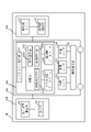
- the driving support system 10 of the present embodiment includes a vehicle 110, a controller 120 which is a vehicle controller, a flying object 130, a display device 140, and the like.
- the driving support system 10 supports remote control of the vehicle 110 by an operator of a driving support center in a remote location.
- the controller 120 may be mounted on the vehicle 110.
- the projectile 130 may be mounted on the vehicle 110 and may be configured to be able to take off and land in response to an instruction from the controller 120.
- the display device 140 is installed in the driving support center and provides an operator who remotely controls the vehicle 110 with an image of the surroundings of the vehicle 110.
- the flying object 130 and the display device 140 are connected to the controller 120 via a communication cable, a wireless network, or the like, respectively, to transmit and receive information.
- the vehicle 110, the flying object 130, and the display device 140 are wirelessly communicated with each other.
- the line connecting each functional block shows the flow of control signals or information to be communicated. Communication between functional blocks may be wired communication or wireless communication.
- the vehicle 110 includes a vehicle communication unit 111, a vehicle camera 112 as a first photographing unit, a range finder 113 as a range finder, a position sensor 114, and the like.
- the vehicle 110 may include, for example, an automobile, an industrial vehicle, a railroad vehicle, a living vehicle, a fixed-wing aircraft traveling on a runway, and the like.
- Automobiles may include, for example, passenger cars, trucks, buses, motorcycles, trolley buses and the like.
- Industrial vehicles may include, for example, industrial vehicles for agriculture and construction.
- Industrial vehicles may include, for example, forklifts, golf carts, and the like.
- Industrial vehicles for agriculture may include, for example, tractors, tillers, transplanters, binders, combines, lawnmowers and the like.
- Industrial vehicles for construction may include, for example, bulldozers, scrapers, excavators, mobile cranes, dump trucks, road rollers and the like.
- the vehicle may include a vehicle that travels manually.
- the vehicle communication unit 111 transmits the video captured by the vehicle camera 112 to the controller communication unit 121.
- the vehicle communication unit 111 transmits the range finder information measured by the range finder 113, the position information measured by the position sensor 114, and the traveling direction of the vehicle 110 to the controller communication unit 121.
- the vehicle camera 112 is installed inside or outside the vehicle 110, and images the surroundings of the vehicle 110 to acquire an image.
- the vehicle camera 112 is installed so as to photograph the front of the vehicle 110.
- the image acquired by the vehicle camera 112 may approximate the scenery that can be visually recognized from the driver's seat of the vehicle 110.
- the vehicle camera 112 may be installed so as to photograph the rear or side of the vehicle 110.
- the range finder 113 measures the distance from the vehicle 110 to surrounding objects and outputs it as range finder information.
- the rangefinder 113 may include, for example, a laser radar, a millimeter wave radar, an ultrasonic sensor, and the like.
- the measured distance measurement information is transmitted by the vehicle communication unit 111 to the controller communication unit 121.
- the position sensor 114 measures the current position of the vehicle 110.
- the position sensor 114 may include a GPS (Global Positioning System), a magnetic azimuth meter, and the like. GPS acquires the absolute position of the vehicle 110 in the horizontal coordinate system by latitude and longitude.
- the magnetic azimuth meter measures the absolute azimuth angle of the vehicle 110 and acquires the traveling direction of the vehicle 110.
- the measured current position and traveling direction of the vehicle 110 are transmitted to the controller communication unit 121 by the vehicle communication unit 111 as position information.
- the controller 120 includes a controller communication unit 121, a calculation unit 122, a three-dimensional map database 123, and the like, which are receiving units.
- the arithmetic unit 122 includes at least one processor in order to provide control and processing power for performing various functions, as described in more detail below.
- at least one processor is executed as a single integrated circuit (IC (Integrated Circuit)) or as a plurality of communicably connected integrated circuit ICs and / or discrete circuits (discrete circuits).
- IC integrated Circuit
- At least one processor can be run according to a variety of known techniques.
- the processor comprises, for example, one or more circuits or units configured to perform one or more data calculation procedures or processes by executing instructions stored in the associated memory.
- the processor may be firmware (eg, a discrete logic component) configured to perform one or more data computation procedures or processes.
- the processor is one or more processors, controllers, microprocessors, microprocessors, application specific integrated circuits (ASICs), digital signal processing units, programmable logic devices, field programmable. The functions described below may be performed, including gate arrays, or any combination of these devices or configurations, or other known device and configuration combinations.
- the calculation unit 122 controls the controller communication unit 121, the calculation unit 122, the three-dimensional map database 123, and the like.
- the controller 120 may be arranged in the vehicle 110, or may be arranged in a place other than the vehicle 110. In the first embodiment, the controller 120 is mounted on the vehicle.
- the controller communication unit 121 receives the image taken by the vehicle camera 112, the range finder information measured by the range finder 113, and the position information measured by the position sensor 114 from the vehicle communication unit 111.
- the controller communication unit 121 transmits the flight position information calculated based on the blind spot region estimated by the calculation unit 122 to the flying object communication unit 131.
- the blind spot area is an area that cannot be observed because the field of view is obstructed by an object in the area that can be observed by the vehicle camera 112.
- the controller communication unit 121 receives the image captured by the flying object camera 132 from the flying object communication unit 131.
- the controller communication unit 121 transmits video information to the display device communication unit 141.
- the calculation unit 122 includes a blind spot estimation unit 122a, a flight calculation unit 122b, and an image processing unit 122c, which are software.
- the calculation unit 122 functions as an area acquisition unit together with the blind spot estimation unit 122a.
- the calculation unit 122 uses these software to estimate the blind spot area, calculate the flight position of the flying object 130, and perform image processing on the image obtained by capturing the blind spot area.
- the blind spot estimation unit 122a, the flight calculation unit 122b, and the image processing unit 122c may be stored in a storage device (not shown).
- the blind spot estimation unit 122a estimates the area where the blind spot occurs within the range of the field of view from the vehicle 110 from the position information of the vehicle 110 measured by the position sensor 114 and the map information acquired from the three-dimensional map database 123.
- the blind spot estimation unit 122a generates a blind spot for the vehicle 110 from the distance information to the object around the vehicle 110 measured by the distance measuring sensor 113, the position information of the vehicle 110, and the map information acquired from the three-dimensional map database 123. Estimate the area to be used.
- the map information is three-dimensional map information around the vehicle 110, and is acquired from the three-dimensional map database 123 based on the position information of the vehicle 110. The method of estimating the blind spot region will be described later.
- the flight calculation unit 122b calculates the flight position of the flying object 130.
- the flight position is a position where the blind spot region estimated by the blind spot estimation unit 122a can be photographed by the flying object camera 132.
- the flight position of the projectile 130 is output as flight position information.
- the flight position information may include coordinate information and the like. The method of calculating the flight position will be described later.
- the image processing unit 122c performs image processing on the image captured by the flying object camera 132. Specifically, for example, the image processing unit 122c recognizes a predetermined object in the image and classifies the type of the object.
- the types of predetermined objects may include, for example, buildings, vehicles, bicycles, people.
- the image processing unit 122c may determine from the type of the object whether it is a dangerous object for the vehicle 110.
- the image processing unit 122c may determine the degree of danger of the object based on the moving speed and direction of the object and the traveling direction of the vehicle 110.
- the image processing unit 122c acquires an image taken by the vehicle camera 112 arranged in the vehicle 110 from the controller communication unit 121.
- the image processing unit 122c superimposes an icon according to the type of the classified object and the degree of danger of the object on the image captured by the vehicle camera 112. How to find the position where the icons are superimposed will be described later.
- the video on which the icon is superimposed is transmitted by the controller communication unit 121 to the display device communication unit 141.
- the three-dimensional map database 123 is composed of a storage medium that stores and manages three-dimensional map information of the traveling area of the vehicle 110.
- the three-dimensional map information includes road information and object information which is information on an object other than the road.
- the road information may include, for example, three-dimensional coordinates such as roads, lanes, white lines, and signs, shapes, sizes, colors, and types.
- the object information may include three-dimensional coordinates, shape, size, color, type, etc. of buildings, facilities, tunnels, and the like.
- the shape and size are represented by, for example, the three-dimensional coordinates of a plurality of endpoints forming the contour of the object.
- a GIS (Geographic Information System) database may be used as the three-dimensional map database.
- the flying object 130 which is a photographing device, includes a flying object communication unit 131, which is an information acquisition unit, a flying object camera 132, which is a second photographing unit, a flying object control unit 133, and the like.
- the projectile 130 may include an unmanned aerial vehicle called a UAV (Unmanned Aerial Vehicle) or a drone.
- UAV Unmanned Aerial Vehicle
- the projectile 130 is mounted on the vehicle 110, and may take off from the vehicle 110 and fly, for example, when the vehicle 110 is remotely controlled from the driving support center.
- the projectile 130 may be able to hover at a predetermined position during flight and may be capable of cruising at high speed.
- the flying object communication unit 131 receives the flight position information of the flying object 130 from the controller communication unit 121.
- the flying object communication unit 131 transmits the image captured by the flying object camera 132 to the controller communication unit 121.
- the flying object camera 132 is installed on the flying object 130 and captures the surroundings of the flying object 130 to acquire an image.
- the flying object camera 132 may be configured so that the shooting direction can be changed by a driving device.
- the projectile camera 132 may be installed so as to photograph the front, bottom, rear, and sides of the projectile 130. In the first embodiment, when the flying object camera 132 photographs the blind spot region, it shall photograph the lower part of the flying object 130.
- the flying object control unit 133 controls a flight mechanism (not shown) to move the flying object 130 to the position indicated by the flight position information.
- the display device 140 includes a display device communication unit 141, a display unit 142, and the like.
- the display device 140 is a device that displays an image created by the image processing unit 122c.
- the display device 140 may be arranged at the driving support center or may be arranged at another place.
- the display device communication unit 141 receives the video created by the image processing unit 122c from the controller communication unit 121.
- the display unit 142 displays the image received by the display device communication unit 141 on the display device 140.
- the displayed image is used when the operator of the driving support center remotely controls the vehicle 110.
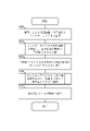
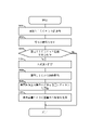
- the vehicle communication unit 111 transmits the range finder information measured by the range finder 113 and the position information measured by the position sensor 114 to the controller communication unit 121 (step S100).
- the blind spot estimation unit 122a estimates the area where the blind spot occurs.
- the flight calculation unit 122b calculates the position where the flying object camera 132 can capture the blind spot region estimated by the blind spot estimation unit 122a as the flight position.
- the blind spot area is an area on the road that cannot be observed because the field of view is obstructed by an object in the area that can be observed by the vehicle camera 112.
- the controller communication unit 121 transmits the flight position information calculated by the flight calculation unit 122b to the flying object communication unit 131 (step S200).
- the flying object control unit 133 controls a flight mechanism (not shown) to move the flying object 130.
- the flying object camera 132 moves to a position in the sky indicated by the flight position information
- the flying object camera 132 captures the blind spot region estimated by the blind spot estimation unit 122a.
- the captured video is transmitted to the controller communication unit 121 (step S300).
- the image processing unit 122c When the controller 120 acquires the image captured by the flying object camera 132, the image processing unit 122c performs image processing on the image captured by the vehicle camera 112. Specifically, the image processing unit 122c superimposes the icon on the image captured by the vehicle camera 112 acquired from the vehicle communication unit 111. The icon may correspond to the type of the object classified by the image processing unit 122c, which is reflected in the image captured by the flying object camera 132.
- the controller communication unit 121 transmits the video on which the icon is superimposed to the display device communication unit 141 (step S400).
- the display device 140 displays the acquired image on the display unit 142 (step S500).
- the video is used by the operator of the driving support center to remotely control the vehicle 110.
- the operator of the driving support center By superimposing the icon on the image, the operator of the driving support center in a remote place can grasp the object existing in the blind spot area.
- the type and display form of the icon may depend on the degree of danger of the object recognized by the image processing unit 122c. The operator can determine whether or not the object is dangerous from the type of icon and the display form.
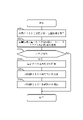
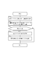
- the controller communication unit 121 acquires the range finder information measured by the range finder 113 and the position information measured by the position sensor 114 (step S211).
- the distance measurement information may include information on the distance from the vehicle 110 to surrounding objects and the like.
- the position information may include information on the current position of the vehicle 110 and the like.
- the calculation unit 122 acquires map information, which is three-dimensional map information around the vehicle 110, from the three-dimensional map database 123 based on the position information acquired in step S211 (step S212).
- the calculation unit 122 determines from the rangefinder information, the position information, and the map information whether or not there is a blind spot whose field of view is blocked by an object in the area that can be observed from the vehicle 110 (step S213).
- the object may include an object registered in the map information and an object not registered in the map information.
- Objects registered in the map information may include, for example, buildings, signs, facilities, tunnels, mountains, and the like.
- Objects that are not registered in the map information may include, for example, large vehicles that are stopped, pedestrians, newly constructed buildings that are not registered in the map information, and other obstacles that exist on the road.
- step S213 If it is determined in step S213 that there is no blind spot, the process ends.
- the blind spot estimation unit 122a estimates the blind spot region to be photographed by the flying object 130 (step S214). The method of estimating the blind spot region will be described later.
- the flight calculation unit 122b calculates the flight position of the flying object 130 (step S215).
- the flight position is a position where the blind spot region estimated in step S214 can be photographed by the flying object camera 132. The method of calculating the flight position will be described later.
- the controller communication unit 121 transmits the flight position calculated in step S215 to the flying object communication unit 131 (step S216), and ends the process.
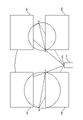
- the objects 60a, 60b, 60c, and 60d may be, for example, a building constructed facing a road.
- the vehicle 110 is observing the intersection formed by the objects 60a, 60b, 60c, 60d from the road facing the objects 60b and 60d.
- the blind spot estimation unit 122a determines whether or not there is a blind spot area that becomes a blind spot from the position information and the map information. Specifically, the range of the field of view from the vehicle 110 (for example, the range of the field of view from the vehicle camera 112, hereinafter referred to as a shooting area) is superposed on the position of the object registered in the map information. At that time, the area where the vehicle 110 cannot see ahead due to the presence of the object (that is, the area where the field of view is obstructed) is determined as the blind spot area.
- the shooting area is defined by a fan shape with a radius R (visibility distance of the vehicle camera 112) and a central angle ⁇ (angle of view of the vehicle camera 112).
- a blind spot area is formed by blocking the field of view of the vehicle camera with the object.
- the shooting area coincides with the predetermined distance range.
- the blind spot region is shown by a broken line, a part of the outline of the object, and the line-of-sight direction from the vehicle-mounted camera 112.
- the blind spot estimation unit 122a obtains the point A (first position), which is the point closest to the vehicle 110, among the areas on the road where the blind spot occurs from the photographed area and the map information. Point A is the point closest to the vehicle 110 among the contours of the object adjacent to the blind spot area.
- the blind spot estimation unit 122a obtains the point B (second position), which is the point farthest from the point A in the blind spot area to which the point A belongs.
- the blind spot area is included in the range of the circle whose diameter is the point A and the point B in the same blind spot area.
- the blind spot estimation unit 122a determines whether or not there is a blind spot region to be a blind spot from the distance measurement information, the position information, and the map information.
- the blind spot estimation unit 122a determines that the area where the field of view from the vehicle 110 is obstructed by an object not registered in the map information is the blind spot area.
- a blind spot area exists in the photographing area due to the object 60e.
- a predetermined distance range which is a shooting area, is defined by a fan shape having a radius R (viewing distance of the vehicle camera 112) and a central angle ⁇ (angle of view of the vehicle camera 112) as described above.
- the blind spot region is shown by a broken line, a part of the outline of the object, and the line-of-sight direction from the vehicle-mounted camera 112.
- the blind spot estimation unit 122a obtains a point A which is the closest point to the vehicle 110 among the areas where the blind spot is generated from the photographing area and the distance measurement information. Since the size and shape of the object not registered in the map information is unknown, the point closest to the vehicle 110 in the area where the object exists is the point A.
- the distance r from the vehicle 110 to the object 60e is measured by the range finder 113.
- the blind spot estimation unit 122a obtains the point B, which is the point farthest from the point A in the blind spot area to which the point A belongs.
- the blind spot area is included in the range of a circle whose diameter is a straight line connecting the points A and B in the same blind spot area.
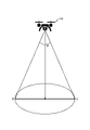
- step S215 A method of calculating the flight position based on the blind spot region estimated by the blind spot estimation unit 122a in step S215 will be described with reference to FIG.
- the flight position is a position where the flying object 130 can photograph this circle from the flying object camera 130 mounted on the flying object 130.
- the flying object camera 132 faces directly below the flying object 130 when photographing the blind spot area. Therefore, the flight position can be calculated based on the angle of view ⁇ of the flying object camera 132 mounted on the flying object 130 and the distance from the point A to the point B.
- the field of view of the flying object camera 130 can be defined by a cone having the angle of view ⁇ of the flying object camera 132 as the apex angle. Therefore, the flight position can be the position of the apex of the cone whose bottom surface is a circle whose diameter is from point A to point B and whose apex angle is ⁇ . That is, the altitude of the flight position corresponds to the height of the cone.
- the flight position of the flying object 130 is limited to the example of the present embodiment as long as the flying object camera 132 can capture a circular region having a diameter of a straight line connecting the points A and B. is not.
- the controller communication unit 121 acquires the image captured by the flying object camera 132 (step S401).
- the image processing unit 122c recognizes the object in the image acquired in step S401 and classifies the type of the object (step S402).
- Types of objects may include, for example, buildings, vehicles, bicycles, people, and the like.
- the image processing unit 122c determines whether or not the object is dangerous to the vehicle 110 from the positions of the objects classified in step S402 (step S403).
- the dangerous object is, for example, an object that may collide with the vehicle 110, and may be, for example, a vehicle, a bicycle, a person, or the like.
- step S403 If it is determined in step S403 that the recognized object is not a dangerous object for the vehicle 110, the process ends.
- the image processing unit 122c estimates the degree of danger of the object based on the moving speed / direction of the object and the traveling direction of the vehicle 110 (step S404).
- the risk level may be divided into multiple levels.
- the controller communication unit 121 acquires the image captured by the vehicle camera 112 (step S405).
- the image processing unit 122c calculates which position on the image captured by the vehicle camera 112 corresponds to the position of the object for which the degree of danger has been determined in step S404.
- the image processing unit 122c superimposes an icon corresponding to the type classified in step S402 on the position where an object dangerous to the vehicle 110 exists on the image acquired in step S405 (step S406).
- the display form of the icon may be changed according to the degree of danger of the object.
- the change in the display form may be, for example, a change in color, transmittance, saturation, lightness, size, or the like, or a change in a dynamic display method such as blinking or moving.
- the controller communication unit 121 transmits the video on which the icon created in step S406 is superimposed to the display device communication unit 141 (step S407).
- FIG. 8 is a diagram showing an image in which an icon is superimposed on an image taken by the vehicle camera 112.
- the image processing unit 122c superimposes the icons 70a, 70b, and 70c corresponding to the type of the object recognized by the image processing unit 122c on the image captured by the vehicle camera 112 to generate the image. ..
- the objects 60a, 60b, 60c, and 60d are buildings registered in the map information acquired from the three-dimensional map database 123.
- the icons 70a and 70b correspond to objects that are determined to be dangerous among the objects existing at positions on the road whose field of view is blocked by the objects 60b and 60d that are buildings.
- the display positions of the icons 70a and 70b correspond to the positions of objects in the image captured by the flying object camera 132.
- the image processing unit 122c may change the display form of the icons 70a, 70b, 70c according to the degree of danger.
- the change in the display form may be, for example, a change in color, transmittance, saturation, lightness, size, or the like, or a change in a dynamic display method such as blinking or moving.
- the image processing unit 122c may display the icons 70a, 70b, and 70c in different colors depending on the degree of danger.
- the icon 70a which is close to the vehicle 110 and has a high risk of approaching the vehicle 110, may be displayed in red.
- the icon 70c which is farther from the vehicle 110 than the icon 70a but has a high risk of approaching the vehicle 110, may be displayed in yellow.
- the icon 70b which is close to the vehicle 110 but has a low risk of approaching the vehicle 110, may be displayed in blue.
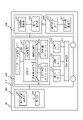
- the driving support system 20 of the present embodiment includes a vehicle 210, a controller 220, a roadside unit 230, a display device 240, and the like.
- the driving support system 20 is different from the driving support system 10 according to the first embodiment in that it includes a roadside machine database 224 and a roadside machine 230 which is a photographing device.
- the configuration and operation of the vehicle 210 and the display device 240 are the same as those of the vehicle 110 and the display device 140 according to the first embodiment, and thus the description thereof will be omitted.
- the roadside unit 230 is connected to the controller 220 via a communication cable, wireless network, etc. to transmit and receive information.
- the controller 220 includes a controller communication unit 221, a calculation unit 222, a three-dimensional map database 223, a roadside machine database 224, and the like.
- the controller 220 controls the controller communication unit 221 and the calculation unit 222, the three-dimensional map database 223, the roadside machine database 224, and the like.
- the controller communication unit 221 transmits a shooting instruction to the roadside unit 230 capable of shooting the blind spot area.
- the controller communication unit 221 receives the image captured by the roadside camera 232 from the roadside unit communication unit 231.
- the calculation unit 222 includes software such as a blind spot estimation unit 222a, a roadside machine selection unit 222d, and an image processing unit 222c.
- the roadside machine selection unit 222d selects the roadside machine 230 for photographing the blind spot area.
- the roadside machine selection unit 222d may be stored in a storage device (not shown).
- the roadside machine selection unit 222d acquires information on the roadside machine 230 capable of photographing the blind spot area from the roadside machine database 224.
- the image processing unit 222c performs image processing of the image taken by the roadside camera 232. Since the configuration and operation of the image processing unit 222c are the same as those of the image processing unit 122c according to the first embodiment, the description thereof will be omitted.
- the roadside machine database 224 is composed of a storage medium that stores and manages roadside machine information, which is information about roadside machines installed in the traveling area of the vehicle 210.
- the roadside machine information may include coordinate information of the position where the roadside machine is installed, information on an area where the roadside machine can be photographed, and the like.
- the roadside machine 230 includes a roadside machine communication unit 231 which is an information acquisition unit, a roadside machine camera 232 which is a second photographing unit, and the like.
- the roadside machine 230 is positioned as V2I (Vehicle to Infrastructure) and is a device that performs coordinated control of a person and a vehicle through collection and distribution of signal information and surrounding information at an intersection.
- V2I Vehicle to Infrastructure
- the roadside unit 230 may send and receive information via a communication network or the like with a vehicle equipped with a system capable of communicating with the roadside unit 230.
- the signal information may include coordinate information of the position of a traffic light installed at an intersection, color information displayed on the traffic light, and the like.
- the surrounding information may include information about the surroundings of the roadside aircraft.
- the roadside unit communication unit 231 receives a shooting instruction from the controller communication unit 221.
- the roadside unit communication unit 231 transmits the video captured by the roadside unit camera 232 to the controller communication unit 221.
- the roadside machine camera 232 is installed in the roadside machine 230 and captures the surroundings of the roadside machine 230 to acquire an image.
- the roadside camera 232 is installed so as to capture a predetermined area on the road.
- the second embodiment is different from the driving support system 10 according to the first embodiment in that the roadside camera 232 captures the blind spot area.
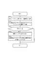
- the driving support processing procedure of the driving support system 20 only the part different from the driving support processing procedure of the driving support system 10 according to the first embodiment will be described.
- steps S221 to S223 is the same as the processing of steps S211 to S213, and thus the description thereof will be omitted.
- the blind spot estimation unit 222a estimates the blind spot area to be photographed by the roadside machine 230 (step S224).
- the roadside machine selection unit 222d selects the roadside machine 230 capable of photographing the blind spot region estimated in step S224 from the roadside machine database 224 (step S225).
- the roadside machine database 224 stores the roadside machine information including the coordinate information of the position where the roadside machine is installed and the information of the area where the roadside machine can be photographed.
- the roadside machine selection unit 222d selects the roadside machine 230 capable of photographing the blind spot area from the blind spot area and the roadside machine information estimated in step S224, and ends the process.
- the second embodiment is different from the driving support system 10 according to the first embodiment in that the image is acquired by the roadside camera 232, but the image processing unit 222c for the image captured by the roadside camera 232 is used. Since the image processing and the method of creating the image to be displayed by the display device 240 are the same as those of the driving support system 10 according to the first embodiment, the description thereof will be omitted.
- the driving support system 30 of the present embodiment includes a vehicle 310, a controller 320, a roadside unit 330, a display device 340, a selection vehicle 350 which is a photographing device, and the like.
- the roadside unit 330 and the selected vehicle 350 are connected to the controller 320 via a communication cable, a wireless network, or the like to transmit and receive information.
- the driving support system 30 is different from the driving support system 10 according to the first embodiment in that it includes a roadside machine database 324, a roadside machine 330, and a selected vehicle 350.
- the configuration and operation of the vehicle 310 are the same as those of the vehicle 110 according to the first embodiment, and thus the description thereof will be omitted. Since the configuration and operation of the display device 340 and the display device 340 are the same as those of the display device 140 and the display device 140 according to the first embodiment, the description thereof will be omitted.
- the controller 320 includes a controller communication unit 321, a calculation unit 322, a three-dimensional map database 323, a roadside machine database 324, and the like.
- the controller 320 controls the controller communication unit 321, the calculation unit 322, the three-dimensional map database 323, the roadside machine database 324, and the like.
- the controller communication unit 321 selects the roadside unit 330 located around the blind spot area.
- the controller communication unit 321 transmits an instruction to select the selected roadside unit 330 to select the selected vehicle 350 capable of photographing the blind spot area.
- the controller communication unit 321 transmits an instruction to photograph the surroundings of the vehicle with the selected vehicle camera 352 to the roadside unit 330.
- the controller communication unit 321 receives the image captured by the selected vehicle camera 352 from the selected vehicle communication unit 351 via the roadside unit communication unit 331.
- the calculation unit 322 includes software such as a blind spot estimation unit 322a, a roadside machine selection unit 322d, and an image processing unit 322c.
- the roadside machine selection unit 322d selects the roadside machine 330 around the blind spot area.
- the roadside machine selection unit 322d acquires the roadside machine 330 around the blind spot area from the roadside machine database 324.
- the image processing unit 322c performs image processing on the image captured by the selected vehicle camera 352. Since the configuration and operation of the image processing unit 322c are the same as those of the image processing unit 122c according to the first embodiment, the description thereof will be omitted.
- the roadside machine database 324 is composed of a storage medium that stores and manages roadside machine information, which is information about roadside machines installed in the traveling area of the vehicle 310.
- the roadside machine information may include coordinate information of the position where the roadside machine is installed.
- the roadside unit 330 includes a roadside unit communication unit 331, a vehicle selection unit 334, and the like.
- the roadside unit communication unit 331 receives an instruction to select the selected vehicle 350 from the controller communication unit 321.
- the roadside unit communication unit 331 transmits a shooting instruction to the selected vehicle communication unit 351.
- the roadside unit communication unit 331 receives the image captured by the selected vehicle camera 352 from the selected vehicle communication unit 351.
- the roadside unit communication unit 331 transmits the image captured by the selected vehicle camera 352 to the controller communication unit 321.
- the vehicle selection unit 334 selects a selection vehicle 350 capable of photographing a blind spot area.
- the roadside unit 330 communicates with a vehicle located at a point where it can communicate with the roadside unit 330, and selects a selected vehicle 350 equipped with a camera capable of photographing a blind spot area.
- the selected vehicle 350 includes a selected vehicle communication unit 351 which is an information acquisition unit, a selected vehicle camera 352 which is a second photographing unit, and the like.
- the selected vehicle 350 may include a vehicle having the same configuration as the vehicle 310 in the present embodiment.
- the selected vehicle communication unit 351 receives a shooting instruction from the roadside unit communication unit 331.
- the selected vehicle communication unit 351 transmits the image captured by the selected vehicle camera 352 to the roadside unit communication unit 331.
- the selected vehicle camera 352 is installed inside or outside the selected vehicle 350, and images the surroundings of the selected vehicle 350 to acquire an image.
- the selected vehicle camera 352 is installed so as to photograph the front of the selected vehicle 350.
- the selected vehicle camera 352 may be installed so as to photograph the rear or side of the selected vehicle 350.
- the third embodiment is different from the driving support system 10 according to the first embodiment in that the selected vehicle camera 352 captures the blind spot area.
- the driving support processing procedure of the driving support system 30 only the part different from the driving support processing procedure of the driving support system 10 according to the first embodiment will be described.
- steps S231 to S233 is the same as the processing of steps S211 to S213, and thus the description thereof will be omitted.
- step S233 If it is determined in step S233 that there is no blind spot, the process ends.
- the blind spot estimation unit 322a estimates the blind spot region to be photographed (step S234).
- the roadside machine selection unit 322d selects the roadside machine 330 around the blind spot region estimated in step S234 from the roadside machine database 324 and ends the process (step S235).
- the roadside machine selection unit 322d selects the roadside machine 330 installed around the blind spot area from the roadside machine database 324 based on the blind spot area estimated in step S234.
- the roadside unit communication unit 331 communicates with a vehicle capable of communicating with the roadside unit 330.
- the vehicle selection unit 334 transmits information regarding the blind spot area to a vehicle capable of communicating with the roadside unit 330.
- the vehicle that has received the information on the blind spot area transmits the information on whether or not the blind spot area can be photographed by the mounted camera to the roadside machine 330.
- the roadside machine 330 selects a vehicle capable of photographing the blind spot area with the mounted camera as the selected vehicle 350.
- the roadside unit communication unit 331 transmits a shooting instruction to the selected vehicle communication unit 351.
- the selected vehicle communication unit 351 receives a shooting instruction from the roadside unit 330, and shoots a blind spot region with the selected vehicle camera 352.
- the captured image is transmitted to the controller communication unit 321 via the roadside unit 330.
- the third embodiment is different from the driving support system 10 according to the first embodiment in that an image is acquired by the selected vehicle camera 352.
- the image processing method of the image processing unit 322c of the image captured by the selected vehicle camera 352 and the method of creating the image to be displayed by the display device 340 are the same as those of the driving support system 10 according to the first embodiment, and thus the description thereof will be omitted.
- the driving support system estimates the area where the blind spot occurs and provides the driver of the vehicle with the surrounding information of the vehicle including the information of the area where the blind spot occurs. be able to.
- the display device 140 is not limited to being installed in a remote driving support center, for example.
- the vehicle 110 does not have to be remotely controlled, and the display device 140 may be mounted on the vehicle 110 to assist the driver in driving.
- the descriptions such as “first” and “second” are identifiers for distinguishing the configuration.
- the configurations distinguished by the descriptions of “first”, “second”, etc. in the present disclosure can exchange numbers in the configurations.
- the first photographing unit can exchange the identifiers “first” and “second” with the second photographing unit.
- the exchange of identifiers takes place at the same time.
- the configuration is distinguished.
- the identifier may be deleted.
- the configuration with the identifier removed is distinguished by a code. Based only on the description of identifiers such as “first” and “second” in the present disclosure, it shall not be used as a basis for interpreting the order of the configurations and for the existence of identifiers with small numbers.
Landscapes
- Engineering & Computer Science (AREA)
- Multimedia (AREA)
- Physics & Mathematics (AREA)
- General Physics & Mathematics (AREA)
- Mechanical Engineering (AREA)
- Signal Processing (AREA)
- Theoretical Computer Science (AREA)
- Aviation & Aerospace Engineering (AREA)
- Traffic Control Systems (AREA)
- Closed-Circuit Television Systems (AREA)
Abstract
Description
60a,60b,60c,60d,60e 物体
70a,70b,70c アイコン
110,210,310 車両
111,211,311 車両通信部
112,212,312 車両カメラ
113,213,313 測距センサ
114,214,314 位置センサ
120,220,320 コントローラ
121,221,321 コントローラ通信部
122,222,322 演算部
122a,222a,322a 死角推定部
122b 飛行演算部
122c,222c,322c 画像処理部
123,223,323 3次元地図データベース
130 飛翔体
131 飛翔体通信部
132 飛翔体カメラ
133 飛翔体制御部
140,240,340 表示装置
141,241,341 表示装置通信部
142,242,342 表示部
222d,322d 路側機選択部
224,324 路側機データベース
230,330 路側機
231,331 路側機通信部
232 路側機カメラ
334 車両選択部
350 選択車両
351 選択車両通信部
352 選択車両カメラ
Claims (8)
- 車両の周囲を撮影する第1の撮影部と、
前記車両の位置を示す位置情報に基づき前記車両の周囲の物体によって前記第1の撮影部の撮影領域内において死角となる領域を死角領域として取得する領域取得部を備える車両コントローラと、
前記死角領域に関する情報を取得する情報取得部と、前記車両の周囲を撮影する第2の撮影部と、を備える撮影装置と、
を有し、前記車両コントローラはさらに前記第2の撮影部で撮影した前記死角領域の画像を受信する受信部を備える運転支援システム。 - 前記領域取得部は、前記車両の周囲の物体の位置を示す物体情報を含む地図情報と前記位置情報に基づき、前記死角領域を取得する、
請求項1に記載の運転支援システム。 - 前記領域取得部は、測距部で測定した前記車両から物体までの距離と前記位置情報に基づき、前記死角領域を取得する、
請求項1又は2に記載の運転支援システム。 - 前記第1の撮影部の撮影領域として、前記第1の撮影部から所定の距離範囲が規定されており、
前記撮影装置は、前記死角領域で前記車両から最も近い位置である第1位置と、前記第1位置から最も離れた位置である第2位置とを結ぶ線を直径とする円によって規定される領域を撮影する、
請求項1から3に記載の運転支援システム。 - 前記撮影装置は、前記死角領域を撮影できる位置に移動する、
請求項4に記載の運転支援システム。 - 前記撮影装置は飛翔体であり、
前記死角領域の大きさと前記第2の撮影部の画角と、に基づいて前記飛翔体は高度を変更する、
請求項5に記載の運転支援システム。 - 周囲を撮影する第1の撮影部と、
現在の位置を示す位置情報に基づき、周囲の物体によって前記第1の撮影部の死角となる領域を死角領域として取得する領域取得部と、
前記死角領域に関する情報に基づき撮影した前記死角領域の映像を撮影装置から取得する受信部と、を備える、
車両。 - 車両の位置を示す位置情報に基づき、前記車両の周囲の物体によって前記車両の周囲の撮影領域を撮影する第1の撮影部の死角となる領域を死角領域として取得する車両コントローラから、前記死角領域に関する情報を取得する情報取得部と、
前記車両の周囲を撮影する第2の撮影部と、
前記第2の撮影部で撮影した前記死角領域の画像を前記車両又は前記車両コントローラに送信する送信部と、
を備える撮影装置。
Priority Applications (2)
| Application Number | Priority Date | Filing Date | Title |
|---|---|---|---|
| EP22739423.6A EP4280195A4 (en) | 2021-01-18 | 2022-01-12 | DRIVING ASSISTANCE SYSTEM, VEHICLE AND IMAGING DEVICE |
| US18/261,063 US20240317141A1 (en) | 2021-01-18 | 2022-01-12 | Driving support system, vehicle, and imaging device |
Applications Claiming Priority (2)
| Application Number | Priority Date | Filing Date | Title |
|---|---|---|---|
| JP2021005862A JP2022110448A (ja) | 2021-01-18 | 2021-01-18 | 運転支援システム、車両、撮影装置 |
| JP2021-005862 | 2021-01-18 |
Publications (1)
| Publication Number | Publication Date |
|---|---|
| WO2022154018A1 true WO2022154018A1 (ja) | 2022-07-21 |
Family
ID=82448403
Family Applications (1)
| Application Number | Title | Priority Date | Filing Date |
|---|---|---|---|
| PCT/JP2022/000771 Ceased WO2022154018A1 (ja) | 2021-01-18 | 2022-01-12 | 運転支援システム、車両、撮影装置 |
Country Status (4)
| Country | Link |
|---|---|
| US (1) | US20240317141A1 (ja) |
| EP (1) | EP4280195A4 (ja) |
| JP (1) | JP2022110448A (ja) |
| WO (1) | WO2022154018A1 (ja) |
Cited By (2)
| Publication number | Priority date | Publication date | Assignee | Title |
|---|---|---|---|---|
| WO2024128060A1 (ja) * | 2022-12-14 | 2024-06-20 | 株式会社小糸製作所 | 視界支援表示装置、視界支援表示システム、および視界支援表示方法 |
| WO2024225045A1 (ja) * | 2023-04-28 | 2024-10-31 | 京セラ株式会社 | 情報処理装置、観察装置、路車協調交通システム、及び情報処理方法 |
Families Citing this family (4)
| Publication number | Priority date | Publication date | Assignee | Title |
|---|---|---|---|---|
| WO2024166318A1 (ja) * | 2023-02-09 | 2024-08-15 | 株式会社RedDotDroneJapan | 撮影システム、撮影方法および撮影プログラム |
| EP4579629A3 (en) * | 2023-12-26 | 2025-08-27 | IT Telecom Co., Ltd. | System for expanding recognition area of vehicle based on surrounding environment information |
| JP7660773B1 (ja) * | 2024-01-25 | 2025-04-11 | 三菱電機株式会社 | 情報処理装置、情報処理システム、ルート評価方法およびプログラム |
| JP7643678B1 (ja) | 2024-05-27 | 2025-03-11 | 株式会社イイガ | 自動運転システム、自動運転方法、移動体、および自動運転プログラム |
Citations (5)
| Publication number | Priority date | Publication date | Assignee | Title |
|---|---|---|---|---|
| JP2007257338A (ja) * | 2006-03-23 | 2007-10-04 | Toyota Central Res & Dev Lab Inc | 潜在危険度推定装置 |
| WO2012169361A1 (ja) | 2011-06-07 | 2012-12-13 | 株式会社小松製作所 | 作業車両の周辺監視装置 |
| JP2016197980A (ja) * | 2015-04-06 | 2016-11-24 | 株式会社Nttファシリティーズ | 診断システム、診断方法、及びプログラム |
| WO2017057157A1 (ja) * | 2015-09-30 | 2017-04-06 | 株式会社ニコン | 飛行装置、移動装置、サーバおよびプログラム |
| US20200020231A1 (en) * | 2018-07-11 | 2020-01-16 | Samsung Electronics Co., Ltd. | In-vehicle infotainment system communicating with unmanned aerial vehicle and method of operating the same |
Family Cites Families (3)
| Publication number | Priority date | Publication date | Assignee | Title |
|---|---|---|---|---|
| JP5053776B2 (ja) * | 2007-09-14 | 2012-10-17 | 株式会社デンソー | 車両用視界支援システム、車載装置、及び、情報配信装置 |
| WO2012131871A1 (ja) * | 2011-03-28 | 2012-10-04 | パイオニア株式会社 | 情報表示装置、制御方法、プログラム、及び記憶媒体 |
| JP6686988B2 (ja) * | 2017-08-28 | 2020-04-22 | 株式会社Soken | 映像出力装置及び映像生成プログラム |
-
2021
- 2021-01-18 JP JP2021005862A patent/JP2022110448A/ja active Pending
-
2022
- 2022-01-12 WO PCT/JP2022/000771 patent/WO2022154018A1/ja not_active Ceased
- 2022-01-12 EP EP22739423.6A patent/EP4280195A4/en not_active Withdrawn
- 2022-01-12 US US18/261,063 patent/US20240317141A1/en not_active Abandoned
Patent Citations (5)
| Publication number | Priority date | Publication date | Assignee | Title |
|---|---|---|---|---|
| JP2007257338A (ja) * | 2006-03-23 | 2007-10-04 | Toyota Central Res & Dev Lab Inc | 潜在危険度推定装置 |
| WO2012169361A1 (ja) | 2011-06-07 | 2012-12-13 | 株式会社小松製作所 | 作業車両の周辺監視装置 |
| JP2016197980A (ja) * | 2015-04-06 | 2016-11-24 | 株式会社Nttファシリティーズ | 診断システム、診断方法、及びプログラム |
| WO2017057157A1 (ja) * | 2015-09-30 | 2017-04-06 | 株式会社ニコン | 飛行装置、移動装置、サーバおよびプログラム |
| US20200020231A1 (en) * | 2018-07-11 | 2020-01-16 | Samsung Electronics Co., Ltd. | In-vehicle infotainment system communicating with unmanned aerial vehicle and method of operating the same |
Cited By (2)
| Publication number | Priority date | Publication date | Assignee | Title |
|---|---|---|---|---|
| WO2024128060A1 (ja) * | 2022-12-14 | 2024-06-20 | 株式会社小糸製作所 | 視界支援表示装置、視界支援表示システム、および視界支援表示方法 |
| WO2024225045A1 (ja) * | 2023-04-28 | 2024-10-31 | 京セラ株式会社 | 情報処理装置、観察装置、路車協調交通システム、及び情報処理方法 |
Also Published As
| Publication number | Publication date |
|---|---|
| US20240317141A1 (en) | 2024-09-26 |
| EP4280195A1 (en) | 2023-11-22 |
| JP2022110448A (ja) | 2022-07-29 |
| EP4280195A4 (en) | 2024-11-20 |
Similar Documents
| Publication | Publication Date | Title |
|---|---|---|
| WO2022154018A1 (ja) | 運転支援システム、車両、撮影装置 | |
| US10748426B2 (en) | Systems and methods for detection and presentation of occluded objects | |
| TWI633524B (zh) | 交通監控系統 | |
| CN102792316B (zh) | 交通信号的映射和检测 | |
| JP7324020B2 (ja) | 交通制御システム | |
| JP6429892B2 (ja) | 車載表示手段上にオブジェクトを表示するための方法、並びに、装置 | |
| US12046049B2 (en) | Automatically detecting traffic signals using sensor data | |
| JP2010134499A (ja) | 遠隔地画像表示装置、遠隔操縦装置、車両制御装置、遠隔操縦システム、遠隔操縦方法、遠隔操縦プログラム、車両制御プログラム、遠隔地画像表示方法、遠隔地画像表示プログラム | |
| US12007765B2 (en) | Method for assisting a user in the remote control of a motor vehicle, computer program product, remote-control device and driver assistance system for a motor vehicle | |
| KR102789444B1 (ko) | 사전 왜곡된 타겟을 사용하는 카메라 정렬 시스템 및 방법 | |
| US10907972B2 (en) | 3D localization device | |
| CN110962744A (zh) | 车辆盲区检测方法和车辆盲区检测系统 | |
| US20210004983A1 (en) | Vehicle pose determination | |
| WO2023146801A1 (en) | Correcting multi-zone motion blur | |
| KR20230007992A (ko) | 차량을 위한 동적으로 로컬화된 센서 | |
| CN112835346A (zh) | 用于控制车辆的方法和系统、及车载自动驾驶系统 | |
| CN112284410A (zh) | 一种基于高精度地图的车联网显示系统 | |
| CN107731005B (zh) | 一种基于云计算的利用幻影成像的车载警示系统 | |
| CN114842075A (zh) | 数据标注方法、装置、存储介质及车辆 | |
| CN109537383A (zh) | 一种基于复杂交通环境的无人驾驶道路结构 | |
| CN208452986U (zh) | 一种用于检测车辆外部环境信息的检测系统 | |
| CN119694153A (zh) | 一种车载无人机超视距路况侦测装置、方法及存储介质 | |
| JP7468075B2 (ja) | 管制制御システム | |
| CN115810283A (zh) | 一种关于车路协同中的路侧感知方法及其系统 | |
| JP6729958B1 (ja) | 表示制御システム、表示制御方法及びプログラム |
Legal Events
| Date | Code | Title | Description |
|---|---|---|---|
| 121 | Ep: the epo has been informed by wipo that ep was designated in this application |
Ref document number: 22739423 Country of ref document: EP Kind code of ref document: A1 |
|
| WWE | Wipo information: entry into national phase |
Ref document number: 18261063 Country of ref document: US |
|
| NENP | Non-entry into the national phase |
Ref country code: DE |
|
| ENP | Entry into the national phase |
Ref document number: 2022739423 Country of ref document: EP Effective date: 20230818 |
|
| WWW | Wipo information: withdrawn in national office |
Ref document number: 2022739423 Country of ref document: EP |