WO2022154068A1 - 電気コネクタ - Google Patents
電気コネクタ Download PDFInfo
- Publication number
- WO2022154068A1 WO2022154068A1 PCT/JP2022/001018 JP2022001018W WO2022154068A1 WO 2022154068 A1 WO2022154068 A1 WO 2022154068A1 JP 2022001018 W JP2022001018 W JP 2022001018W WO 2022154068 A1 WO2022154068 A1 WO 2022154068A1
- Authority
- WO
- WIPO (PCT)
- Prior art keywords
- terminal
- base
- recess
- electric
- connector
- Prior art date
- Legal status (The legal status is an assumption and is not a legal conclusion. Google has not performed a legal analysis and makes no representation as to the accuracy of the status listed.)
- Ceased
Links
Images



Classifications
-
- H—ELECTRICITY
- H01—ELECTRIC ELEMENTS
- H01R—ELECTRICALLY-CONDUCTIVE CONNECTIONS; STRUCTURAL ASSOCIATIONS OF A PLURALITY OF MUTUALLY-INSULATED ELECTRICAL CONNECTING ELEMENTS; COUPLING DEVICES; CURRENT COLLECTORS
- H01R13/00—Details of coupling devices of the kinds covered by groups H01R12/70 or H01R24/00 - H01R33/00
- H01R13/62—Means for facilitating engagement or disengagement of coupling parts or for holding them in engagement
- H01R13/629—Additional means for facilitating engagement or disengagement of coupling parts, e.g. aligning or guiding means, levers, gas pressure electrical locking indicators, manufacturing tolerances
-
- H—ELECTRICITY
- H01—ELECTRIC ELEMENTS
- H01R—ELECTRICALLY-CONDUCTIVE CONNECTIONS; STRUCTURAL ASSOCIATIONS OF A PLURALITY OF MUTUALLY-INSULATED ELECTRICAL CONNECTING ELEMENTS; COUPLING DEVICES; CURRENT COLLECTORS
- H01R13/00—Details of coupling devices of the kinds covered by groups H01R12/70 or H01R24/00 - H01R33/00
- H01R13/62—Means for facilitating engagement or disengagement of coupling parts or for holding them in engagement
- H01R13/629—Additional means for facilitating engagement or disengagement of coupling parts, e.g. aligning or guiding means, levers, gas pressure electrical locking indicators, manufacturing tolerances
- H01R13/631—Additional means for facilitating engagement or disengagement of coupling parts, e.g. aligning or guiding means, levers, gas pressure electrical locking indicators, manufacturing tolerances for engagement only
-
- B—PERFORMING OPERATIONS; TRANSPORTING
- B60—VEHICLES IN GENERAL
- B60K—ARRANGEMENT OR MOUNTING OF PROPULSION UNITS OR OF TRANSMISSIONS IN VEHICLES; ARRANGEMENT OR MOUNTING OF PLURAL DIVERSE PRIME-MOVERS IN VEHICLES; AUXILIARY DRIVES FOR VEHICLES; INSTRUMENTATION OR DASHBOARDS FOR VEHICLES; ARRANGEMENTS IN CONNECTION WITH COOLING, AIR INTAKE, GAS EXHAUST OR FUEL SUPPLY OF PROPULSION UNITS IN VEHICLES
- B60K1/00—Arrangement or mounting of electrical propulsion units
- B60K1/04—Arrangement or mounting of electrical propulsion units of the electric storage means for propulsion
-
- B—PERFORMING OPERATIONS; TRANSPORTING
- B60—VEHICLES IN GENERAL
- B60L—PROPULSION OF ELECTRICALLY-PROPELLED VEHICLES; SUPPLYING ELECTRIC POWER FOR AUXILIARY EQUIPMENT OF ELECTRICALLY-PROPELLED VEHICLES; ELECTRODYNAMIC BRAKE SYSTEMS FOR VEHICLES IN GENERAL; MAGNETIC SUSPENSION OR LEVITATION FOR VEHICLES; MONITORING OPERATING VARIABLES OF ELECTRICALLY-PROPELLED VEHICLES; ELECTRIC SAFETY DEVICES FOR ELECTRICALLY-PROPELLED VEHICLES
- B60L53/00—Methods of charging batteries, specially adapted for electric vehicles; Charging stations or on-board charging equipment therefor; Exchange of energy storage elements in electric vehicles
- B60L53/10—Methods of charging batteries, specially adapted for electric vehicles; Charging stations or on-board charging equipment therefor; Exchange of energy storage elements in electric vehicles characterised by the energy transfer between the charging station and the vehicle
- B60L53/14—Conductive energy transfer
- B60L53/16—Connectors, e.g. plugs or sockets, specially adapted for charging electric vehicles
-
- B—PERFORMING OPERATIONS; TRANSPORTING
- B60—VEHICLES IN GENERAL
- B60L—PROPULSION OF ELECTRICALLY-PROPELLED VEHICLES; SUPPLYING ELECTRIC POWER FOR AUXILIARY EQUIPMENT OF ELECTRICALLY-PROPELLED VEHICLES; ELECTRODYNAMIC BRAKE SYSTEMS FOR VEHICLES IN GENERAL; MAGNETIC SUSPENSION OR LEVITATION FOR VEHICLES; MONITORING OPERATING VARIABLES OF ELECTRICALLY-PROPELLED VEHICLES; ELECTRIC SAFETY DEVICES FOR ELECTRICALLY-PROPELLED VEHICLES
- B60L53/00—Methods of charging batteries, specially adapted for electric vehicles; Charging stations or on-board charging equipment therefor; Exchange of energy storage elements in electric vehicles
- B60L53/80—Exchanging energy storage elements, e.g. removable batteries
-
- H—ELECTRICITY
- H01—ELECTRIC ELEMENTS
- H01M—PROCESSES OR MEANS, e.g. BATTERIES, FOR THE DIRECT CONVERSION OF CHEMICAL ENERGY INTO ELECTRICAL ENERGY
- H01M50/00—Constructional details or processes of manufacture of the non-active parts of electrochemical cells other than fuel cells, e.g. hybrid cells
- H01M50/50—Current conducting connections for cells or batteries
- H01M50/543—Terminals
-
- B—PERFORMING OPERATIONS; TRANSPORTING
- B60—VEHICLES IN GENERAL
- B60K—ARRANGEMENT OR MOUNTING OF PROPULSION UNITS OR OF TRANSMISSIONS IN VEHICLES; ARRANGEMENT OR MOUNTING OF PLURAL DIVERSE PRIME-MOVERS IN VEHICLES; AUXILIARY DRIVES FOR VEHICLES; INSTRUMENTATION OR DASHBOARDS FOR VEHICLES; ARRANGEMENTS IN CONNECTION WITH COOLING, AIR INTAKE, GAS EXHAUST OR FUEL SUPPLY OF PROPULSION UNITS IN VEHICLES
- B60K1/00—Arrangement or mounting of electrical propulsion units
- B60K1/04—Arrangement or mounting of electrical propulsion units of the electric storage means for propulsion
- B60K2001/0405—Arrangement or mounting of electrical propulsion units of the electric storage means for propulsion characterised by their position
- B60K2001/0422—Arrangement under the front seats
-
- B—PERFORMING OPERATIONS; TRANSPORTING
- B60—VEHICLES IN GENERAL
- B60K—ARRANGEMENT OR MOUNTING OF PROPULSION UNITS OR OF TRANSMISSIONS IN VEHICLES; ARRANGEMENT OR MOUNTING OF PLURAL DIVERSE PRIME-MOVERS IN VEHICLES; AUXILIARY DRIVES FOR VEHICLES; INSTRUMENTATION OR DASHBOARDS FOR VEHICLES; ARRANGEMENTS IN CONNECTION WITH COOLING, AIR INTAKE, GAS EXHAUST OR FUEL SUPPLY OF PROPULSION UNITS IN VEHICLES
- B60K1/00—Arrangement or mounting of electrical propulsion units
- B60K1/04—Arrangement or mounting of electrical propulsion units of the electric storage means for propulsion
- B60K2001/0455—Removal or replacement of the energy storages
-
- B—PERFORMING OPERATIONS; TRANSPORTING
- B60—VEHICLES IN GENERAL
- B60K—ARRANGEMENT OR MOUNTING OF PROPULSION UNITS OR OF TRANSMISSIONS IN VEHICLES; ARRANGEMENT OR MOUNTING OF PLURAL DIVERSE PRIME-MOVERS IN VEHICLES; AUXILIARY DRIVES FOR VEHICLES; INSTRUMENTATION OR DASHBOARDS FOR VEHICLES; ARRANGEMENTS IN CONNECTION WITH COOLING, AIR INTAKE, GAS EXHAUST OR FUEL SUPPLY OF PROPULSION UNITS IN VEHICLES
- B60K1/00—Arrangement or mounting of electrical propulsion units
- B60K1/04—Arrangement or mounting of electrical propulsion units of the electric storage means for propulsion
- B60K2001/0455—Removal or replacement of the energy storages
- B60K2001/0466—Removal or replacement of the energy storages from above
-
- B—PERFORMING OPERATIONS; TRANSPORTING
- B60—VEHICLES IN GENERAL
- B60L—PROPULSION OF ELECTRICALLY-PROPELLED VEHICLES; SUPPLYING ELECTRIC POWER FOR AUXILIARY EQUIPMENT OF ELECTRICALLY-PROPELLED VEHICLES; ELECTRODYNAMIC BRAKE SYSTEMS FOR VEHICLES IN GENERAL; MAGNETIC SUSPENSION OR LEVITATION FOR VEHICLES; MONITORING OPERATING VARIABLES OF ELECTRICALLY-PROPELLED VEHICLES; ELECTRIC SAFETY DEVICES FOR ELECTRICALLY-PROPELLED VEHICLES
- B60L2250/00—Driver interactions
- B60L2250/16—Driver interactions by display
-
- B—PERFORMING OPERATIONS; TRANSPORTING
- B60—VEHICLES IN GENERAL
- B60Y—INDEXING SCHEME RELATING TO ASPECTS CROSS-CUTTING VEHICLE TECHNOLOGY
- B60Y2200/00—Type of vehicle
- B60Y2200/10—Road Vehicles
- B60Y2200/12—Motorcycles, Trikes; Quads; Scooters
-
- H—ELECTRICITY
- H01—ELECTRIC ELEMENTS
- H01R—ELECTRICALLY-CONDUCTIVE CONNECTIONS; STRUCTURAL ASSOCIATIONS OF A PLURALITY OF MUTUALLY-INSULATED ELECTRICAL CONNECTING ELEMENTS; COUPLING DEVICES; CURRENT COLLECTORS
- H01R11/00—Individual connecting elements providing two or more spaced connecting locations for conductive members which are, or may be, thereby interconnected, e.g. end pieces for wires or cables supported by the wire or cable and having means for facilitating electrical connection to some other wire, terminal, or conductive member, blocks of binding posts
- H01R11/11—End pieces or tapping pieces for wires, supported by the wire and for facilitating electrical connection to some other wire, terminal or conductive member
- H01R11/12—End pieces terminating in an eye, hook, or fork
-
- H—ELECTRICITY
- H01—ELECTRIC ELEMENTS
- H01R—ELECTRICALLY-CONDUCTIVE CONNECTIONS; STRUCTURAL ASSOCIATIONS OF A PLURALITY OF MUTUALLY-INSULATED ELECTRICAL CONNECTING ELEMENTS; COUPLING DEVICES; CURRENT COLLECTORS
- H01R13/00—Details of coupling devices of the kinds covered by groups H01R12/70 or H01R24/00 - H01R33/00
- H01R13/40—Securing contact members in or to a base or case; Insulating of contact members
- H01R13/405—Securing in non-demountable manner, e.g. moulding, riveting
-
- H—ELECTRICITY
- H01—ELECTRIC ELEMENTS
- H01R—ELECTRICALLY-CONDUCTIVE CONNECTIONS; STRUCTURAL ASSOCIATIONS OF A PLURALITY OF MUTUALLY-INSULATED ELECTRICAL CONNECTING ELEMENTS; COUPLING DEVICES; CURRENT COLLECTORS
- H01R13/00—Details of coupling devices of the kinds covered by groups H01R12/70 or H01R24/00 - H01R33/00
- H01R13/73—Means for mounting coupling parts to apparatus or structures, e.g. to a wall
- H01R13/74—Means for mounting coupling parts in openings of a panel
- H01R13/748—Means for mounting coupling parts in openings of a panel using one or more screws
-
- H—ELECTRICITY
- H01—ELECTRIC ELEMENTS
- H01R—ELECTRICALLY-CONDUCTIVE CONNECTIONS; STRUCTURAL ASSOCIATIONS OF A PLURALITY OF MUTUALLY-INSULATED ELECTRICAL CONNECTING ELEMENTS; COUPLING DEVICES; CURRENT COLLECTORS
- H01R2201/00—Connectors or connections adapted for particular applications
- H01R2201/26—Connectors or connections adapted for particular applications for vehicles
-
- H—ELECTRICITY
- H01—ELECTRIC ELEMENTS
- H01R—ELECTRICALLY-CONDUCTIVE CONNECTIONS; STRUCTURAL ASSOCIATIONS OF A PLURALITY OF MUTUALLY-INSULATED ELECTRICAL CONNECTING ELEMENTS; COUPLING DEVICES; CURRENT COLLECTORS
- H01R4/00—Electrically-conductive connections between two or more conductive members in direct contact, i.e. touching one another; Means for effecting or maintaining such contact; Electrically-conductive connections having two or more spaced connecting locations for conductors and using contact members penetrating insulation
- H01R4/28—Clamped connections, spring connections
- H01R4/30—Clamped connections, spring connections utilising a screw or nut clamping member
- H01R4/34—Conductive members located under head of screw
Definitions
- the present invention relates to an electrical connector that is electrically connected to the mating connector.
- Male connectors and female connectors are widely used as connectors for electrically connecting electrical devices to each other.
- the male connector has a plurality of male terminals.
- the female connector has a plurality of female terminals. As the male terminal is inserted into the female terminal, the electrical devices are electrically connected to each other. As a result, electric power, signals, and the like can be exchanged between electrical devices.
- a guide pin may be provided on either the male connector or the female connector.
- a guide hole is formed on the remaining side.
- the guide pin is inserted into the guide hole before the male terminal is inserted into the female terminal.
- the male terminal and the female terminal are aligned. Therefore, it is easy to guide the male terminal toward the female terminal. It is also easy to insert the male terminal into the female terminal after guidance.
- the present invention aims to solve the above-mentioned problems.
- the electric connector includes an electric terminal that is electrically connected to the other terminal provided in the other connector.
- a base that supports the electrical terminals and A guide pin supported by the base and inserted into a guide hole formed in the mating connector, With A recess is formed on the side wall of the guide pin so as to sink toward the inside of the guide pin.
- an electric connector in which the base is embedded in the recess is provided.
- a recess is formed in the guide pin supported by the base.
- a base is embedded in the recess. This embedding holds the guide pin on the base. Therefore, for example, when a tensile force or a tilting force acts on the guide pin when the male terminal is separated from the female terminal, the guide pin is prevented from coming off from the terminal.
- FIG. 1 is an overall schematic side view of an electric vehicle including a male connector as an electric connector according to an embodiment of the present invention.
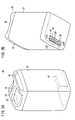
- FIG. 2A is a schematic overall perspective view of a battery pack including a female connector as a mating connector that is electrically connected to the male connector of FIG.
- FIG. 2B is a schematic overall perspective view of the battery pack as viewed from another direction.
- FIG. 3 is a schematic perspective view of the male connector shown in FIG.
- FIG. 4 is a schematic perspective sectional view of the male connector.
- FIG. 5 is an enlarged view of a main part of FIG.
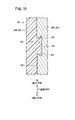
- FIG. 6 is a cross-sectional view of a main part of the guide pin and the first base (base) viewed from a direction orthogonal to the insertion / removal direction.
- FIG. 1 is an overall schematic side view of an electric vehicle including a male connector as an electric connector according to an embodiment of the present invention.
- FIG. 2A is a schematic overall perspective view of a battery pack including a female connector
- FIG. 7 is a vertical cross-sectional view of a main part showing a state in which the male connector of FIG. 1 and the female connector of FIG. 2B are connected.
- FIG. 8 is an exploded view of a main part showing a state in which the male connector and the female connector are separated from each other from FIG. 7.
- FIG. 9 is a schematic flow showing a process of manufacturing a guide pin or a guide pin with a flange from round bars having different diameters.
- FIG. 10 is a cross-sectional view of a main part in which a concave portion and a convex portion having a shape different from that of FIG. 6 are visually recognized from a direction orthogonal to the insertion / extraction direction.
- FIG. 1 is an overall schematic side view of the electric vehicle 12.
- the electric vehicle 12 includes a male connector 10 as an electric connector.
- the electric vehicle 12 is a saddle-mounted electric tricycle.
- a drive motor 16 as a traveling driving force source is arranged in the vicinity of the two rear wheels 14.
- the electric vehicle 12 has a seat 20 in which the user is seated and a seat holding portion 22 for holding the seat 20.
- a battery pack accommodating portion 24 is formed inside the seat holding portion 22.
- the male connector 10 is arranged closer to the front of the vehicle body at the bottom of the battery pack accommodating portion 24.
- the male connector 10 extends along the vehicle width direction. The configuration of the male connector 10 will be described in detail later.
- the seat 20 can be rotated by a rotating shaft (not shown) provided in front of the vehicle body (direction of arrow Z1 in FIG. 1).
- An opening 26 is provided above the battery pack accommodating portion 24.
- the opening 26 is closed.
- the seat 20 seated on the seat holding portion 22 is locked by a lock mechanism (not shown). As a result, the sheet 20 becomes non-rotatable.
- the opening 26 of the battery pack accommodating portion 24 opens. It becomes a state.
- the battery pack 30 (see FIGS. 2A and 2B) can be accommodated in the battery pack accommodating portion 24 through the open opening 26. It is also possible to take out the battery pack 30 from the battery pack accommodating portion 24. That is, the battery pack 30 is detachably housed in the battery pack accommodating portion 24. By supplying electric power from the battery pack 30 to the drive motor 16, the electric vehicle 12 can travel.
- FIG. 2A is a schematic overall perspective view when the battery pack 30 is visually recognized from a predetermined direction.
- FIG. 2B is a schematic overall perspective view when the battery pack 30 is visually recognized from another direction.
- the battery pack 30 has a casing 32 having a vertically long substantially rectangular cuboid shape. When the casing 32 is viewed in a plan view, its shape is substantially square or substantially rectangular.
- a battery core pack holding a plurality of single cells is housed inside the casing 32.
- the single cell consists of, for example, a lithium secondary battery.
- the capacity storage amount
- the capacity of the secondary battery is restored by receiving power from the charging device.
- the single cell can be repeatedly charged and discharged. Since such a configuration of the battery pack 30 is known, detailed description and illustration of a single cell and the like will be omitted.
- An arch portion 34 and a tab-shaped protrusion 36 are provided on the upper surface of the casing 32.
- the arch portion 34 has an arch shape because both ends in the longitudinal direction are bent and connected to the upper surface of the casing 32.
- the upper edge of the tab-shaped protrusion 36 is curved in an arc shape.
- the arch portion 34 and the tab-shaped protrusion 36 face each other.
- a bar-shaped grip portion 38 is bridged from the upper end of the arch portion 34 to the upper end of the tab-shaped protruding portion 36.
- Both upper ends of the arch portion 34 and the tab-shaped protrusion 36 project from the upper surface of the casing 32. Therefore, the bar-shaped grip portion 38 is separated from the upper surface of the casing 32. Therefore, a clearance 40 is formed between the bar-shaped grip portion 38 and the upper surface of the casing 32. The user can insert a hand (finger) into the clearance 40 to grip the bar-shaped grip portion 38.
- a female connector 42 as a mating connector is provided on the bottom surface of the casing 32.
- the female connector 42 is closer to the arch 34.
- the female connector 42 is electrically connected to the male connector 10 when the battery pack 30 is housed in the battery pack housing portion 24.
- FIG. 3 is a schematic perspective view of the male connector 10 as the electric connector according to the present embodiment.
- FIG. 4 is a schematic perspective sectional view of the male connector 10.
- the male connector 10 includes a first base 50, a plurality of male terminals 52a to 52 g (7 in this embodiment), and a plurality of guide pins 54L and 54R (2 in this embodiment). Be prepared.
- the first base 50 includes a flange portion 56, two fixing tab portions 58L, 58R, five lower terminal surrounding portions 60b to 60f, two pin support portions 62L, 62R, and seven upper terminal surroundings. It is a single member integrally having portions 64a to 64g.
- the flange portion 56 extends along the vehicle width direction.
- the fixed tab portions 58L and 58R and the lower terminal surrounding portions 60b to 60f project downward from the lower surface of the flange portion 56.
- the pin support portions 62L and 62R and the upper terminal surrounding portions 64a to 64g project upward from the upper surface of the flange portion 56.
- the first base 50 is provided with a thin-walled support wall portion 66.
- the support wall portion 66 is located between the left and right pin support portions 62L and 62R facing the front of the vehicle body.
- the end faces of the support wall portion 66 facing the rear of the vehicle body and the end faces of the upper terminal surrounding portions 64a to 64 g facing the front of the vehicle body are connected to each other.
- the first base 50 is made of, for example, a thermoplastic resin and exhibits insulating properties.
- the parallel direction (vehicle width direction) of the male terminals 52a to 52g is the longitudinal direction of the flange portion 56.
- the flange portion 56 is a substantially track-shaped portion.
- Mounting holes 68L and 68R are formed at both ends of the flange portion 56, respectively.
- Mounting screws (not shown) are passed through the mounting holes 68L and 68R.
- a screw hole (not shown) is formed at the bottom of the battery pack accommodating portion 24 (see FIG. 1). The mounting screw is screwed into this screw hole. As a result, the male connector 10 is positioned and fixed in the battery pack accommodating portion 24.
- the male terminals 52a to 52g are good conductors made of a metal such as copper. Of these, the male terminals 52b to 52f are covered from the vicinity of the lower end portion to the middle portion in the height direction (vertical direction of the vehicle body) by the lower terminal surrounding portions 60b to 60f and the upper terminal surrounding portions 64b to 64g. In other words, both ends of the five male terminals 52b to 52f in the longitudinal direction along the vertical direction of the vehicle body are exposed from the first base 50.
- the front portion of the lower end portion of the male terminal 52a located at the left end is covered with the fixed tab portion 58L.
- the rear portion of the lower end portion of the male terminal 52a is exposed from the fixed tab portion 58L.
- a nut insertion hole 70 is formed in the fixed tab portion 58L.
- the rear portion of the lower end portion of the male terminal 52a is adjacent to the nut insertion hole 70.
- the front portion of the lower end portion of the male terminal 52 g located at the right end is covered with the fixed tab portion 58R as shown in FIG.
- the rear portion of the lower end portion of the male terminal 52 g is exposed from the fixed tab portion 58R.
- a nut insertion hole 70 is formed in the fixed tab portion 58R.
- the rear portion of the lower end of the male terminal 52 g is adjacent to the nut insertion hole 70.
- Bolt insertion holes 71 are formed at the lower ends of the male terminals 52a and 52g. Further, a bolt exposed hole 72 is formed inward of the nut insertion hole 70 in the vehicle width direction.
- the bolt insertion hole 71, the nut insertion hole 70, and the bolt exposure hole 72 are connected along the left-right direction of the vehicle body.
- the nut insertion hole 70 is an accommodating hole for accommodating the fixing nut 74, and is a bolt hole through which the fixing bolt 80 is passed.
- a window portion 82 opens at the end faces of the fixed tab portions 58L and 58R facing the rear of the vehicle body.
- the window portion 82 is connected to the nut insertion hole 70. Therefore, the fixed tab portions 58L and 58R have three open ends, that is, the left portion of the vehicle body, the right portion of the vehicle body, and the rear portion of the vehicle body.
- a lower lightening 84a and an upper lightening 84b are formed in the vicinity of the window portion 82 and the nut insertion hole 70.
- the lower lightening 84a and the upper lightening 84b form a substantially truck shape extending along the vehicle width direction.
- the lower lightening 84a and the upper lightening 84b are not connected to the window portion 82 or the nut insertion hole 70.
- the lower lightening 84a and the upper lightening 84b are recessed toward the front of the vehicle body until they reach a predetermined depth.
- the lower ends of the guide pins 54L and 54R are embedded in the pin support portions 62L and 62R provided on the first base 50, respectively (see particularly FIG. 4).
- the upper ends of the guide pins 54L and 54R extend upward from the pin support portions 62L and 62R, respectively.
- the pin support portions 62L and 62R are provided at positions sandwiching the seven upper terminal surrounding portions 64a to 64g. Therefore, the male terminals 52a to 52g are sandwiched between the guide pins 54L and 54R.
- each of the guide pins 54L and 54R is formed with an annular groove-shaped annular recess 86 (recess) that goes around along the side peripheral wall.
- the annular recess 86 is recessed toward the inside of the guide pins 54L and 54R.
- the annular recess 86 has a concave lower surface 88 located below, a concave upper surface 90 located above, and a concave peripheral surface 92 (insertion / removal direction surface) located between the concave lower surface 88 and the concave upper surface 90.
- the first base 50 is formed with a flange-shaped convex portion 94 projecting toward the annular recess 86.
- the flange-shaped convex portion 94 has a convex lower surface 96 that contacts the concave lower surface 88, a convex upper surface 98 that contacts the concave upper surface 90, and a convex peripheral surface 100 that surrounds the concave peripheral surface 92.
- the concave lower surface 88 corresponds to the concave side surface
- the convex lower surface 96 corresponds to the covering surface.
- the guide pins 54L and 54R are held by the pin support portions 62L and 62R by embedding the flange-shaped convex portion 94 in the annular concave portion 86 and covering the convex lower surface 96 with the concave lower surface 88. Further, the guide pins 54L and 54R are prevented from coming off from the pin support portions 62L and 62R. This point will be described later.
- FIG. 6 shows a cross section of the guide pins 54L and 54R viewed from a direction orthogonal to the insertion / extraction direction Y described later.
- the height H of the annular recess 86 is larger than the depth DP of the annular recess 86.
- the distance (height H) from the concave lower surface 88 to the concave upper surface 90 of the concave peripheral surface 92 is the distance (height H) from the opening of the annular recess 86 of the concave lower surface 88 and the concave upper surface 90 to the concave peripheral surface 92. It is longer than the depth DP).
- knurling 102 it is preferable to apply knurling 102 to at least one of the concave lower surface 88, the concave upper surface 90, the concave peripheral surface 92, or the side peripheral walls of the guide pins 54L and 54R. In the illustrated example, the case where the side peripheral walls of the guide pins 54L and 54R are knurled 102 is shown.
- the male connector 10 including the first base 50, male terminals 52a to 52g, and guide pins 54L and 54R can be manufactured, for example, by molding. That is, the male terminals 52a to 52g and the guide pins 54L and 54R are preliminarily housed in the cavity of the molding die. After closing the mold, the melt of the thermoplastic resin is injected into the cavity. When the melt is cooled and cured after a lapse of a predetermined time, the first base 50 made of a thermoplastic resin is obtained.
- a harness 110 is attached to the male terminals 52a to 52g.
- the harness 110 is a bundle in which two power lines 112a and 112g and five signal transmission lines 114b to 114f are bundled.
- Power lines 112a and 112g are electrically connected to the lower ends of the male terminals 52a and 52g.
- Signal transmission lines 114b to 114f are electrically connected to the lower ends of the male terminals 52b to 52f, respectively.
- the male terminal 52 g and the power line 112 g are connected via a fixing bolt 80 and a fixing nut 74.
- a crimp terminal 116 having a round hole is attached to the tip of the power line 112 g.
- the fixing nut 74 is inserted into the nut insertion hole 70.
- the body of the fixing bolt 80 is passed through a round hole and a bolt insertion hole 71 of a male terminal 52 g.
- the screw portion provided on the side wall of the body portion is screwed into the screw portion provided on the inner peripheral wall of the fixing nut 74.
- the crimp terminal 116 comes into close contact with the lower end of the male terminal 52 g.
- the body of the fixing bolt 80 is exposed from the bolt exposed hole 72 of the fixing tab portion 58R.
- the positional relationship between the fixed tab portion 58L and the male terminal 52a is mirror-symmetrical with the positional relationship between the fixed tab portion 58R and the male terminal 52g. Therefore, in the fixed tab portion 58L and the male terminal 52a, the same components as those of the fixed tab portion 58R and the male terminal 52g are designated by the same reference numerals, and detailed description thereof will be omitted.
- the female connector 42 provided in the battery pack 30 has a second base 120 and seven female terminals 122a to 122g.
- the female terminals 122a to 122g are supported by the second base 120.
- the second base 120 is, for example, an insulator made of an insulating thermoplastic resin or the like.
- the female terminals 122a to 122g are good conductors made of a metal such as copper, for example.
- the second base 120 is formed with seven accommodating holes 124a to 124g extending upward from the lower surface.
- the accommodation holes 124a to 124g are linearly arranged in parallel along the longitudinal direction of the second base 120 (in this case, the horizontal direction parallel to the arch portion 34 and the vehicle width direction).
- a cover member 126 is attached to the lower surface of the second base 120 via two connecting pins 127.
- the cover member 126 extends from the accommodating hole 124a to the accommodating hole 124g.
- a plurality of insertion ports 128 are formed in the cover member 126.
- One outlet 128 has a substantially rectangular shape.
- the plurality of outlets 128 are connected to the accommodating holes 124a to 124g, respectively.
- An insertion groove 130 for inserting the support wall portion 66 is formed between the second base 120 and the cover member 126.
- Two guide holes 132L and 132R are opened on the lower surface of the second base 120.
- the guide holes 132L and 132R are formed at positions sandwiching the seven accommodating holes 124a to 124g.
- the battery pack 30 is positioned and fixed as the guide pins 54L and 54R are inserted into the guide holes 132L and 132R.
- tab portions 136 are formed so as to protrude on both side surfaces of the second base 120.
- Screw insertion holes 134 are formed in both tab portions 136, respectively.
- a screw (not shown) for attaching the second base 120 to the casing 32 is passed through the screw insertion hole 134.
- the female terminals 122a to 122g are held by the second base 120.
- Each of the female terminals 122a to 122g has two terminal plates.
- Male terminals 52a to 52g are inserted between the lower ends of the two terminal plates of the female terminals 122a to 122g, respectively.
- the upper ends of both terminal plates are joined to each other and protrude from the second base 120.
- the protruding upper end serves as an electrical contact with a single cell in the casing 32.
- the female terminals 122a and 122g are power transmission terminals for transmitting power between the single cell and the external load (or charging device). Therefore, a power line (not shown) is electrically connected to the upper ends of the female terminals 122a and 122g.
- the female terminals 122b to 122f are signal transmission terminals for transmitting a signal between the cell and the external load (or charging device). Therefore, a signal transmission line (not shown) is electrically connected to the upper ends of the female terminals 122b to 122f.
- the annular recesses 86 of the guide pins 54L and 54R are formed by cutting or grinding the round bar 150 as shown in the lower part of FIG. That is, by scraping the side peripheral wall of the round bar 150 along the circumferential direction, an annular recess 86 having three surfaces (all of which are referred to in FIG. 6) of the concave lower surface 88, the concave upper surface 90, and the concave peripheral surface 92 is formed. After that, the upper end side is tapered. Further, preferably, at least one of the concave lower surface 88, the concave upper surface 90, the concave peripheral surface 92, or the side peripheral wall is subjected to knurling 102. As described above, the guide pins 54L and 54R are manufactured.
- FIG. 9 shows the case where the guide pin 154 with a flange is manufactured from the round bar 152.
- the diameter DM of the flanged guide pin 154 is the same as the diameter of the guide pins 54L and 54R.
- the flanged guide pin 154 has a so-called outer flange 156.
- the diameter of the round bar 152 is reduced by cutting or grinding most of the side peripheral walls.
- the diameter of the part that has not been cut or ground is not reduced. This portion serves as an outer flange 156 that projects relative to the reduced diameter side peripheral wall.
- the guide pin 154 with a flange is manufactured.
- the round bar 150 for obtaining the guide pins 54L and 54R in which the annular recess 86 is formed is compared with the round bar 152 for obtaining the flanged guide pin 154 having the outer flange 156. It has a small diameter. Moreover, the amount of cutting to obtain the guide pins 54L and 54R from the round bar 150 is smaller than the amount of cutting to obtain the guide pin 154 with a flange from the round bar 152. That is, when the male connector 10 is obtained by adopting the guide pins 54L and 54R, resource saving can be achieved as compared with the case where the guide pin 154 with a flange is adopted. In addition, since the amount of shaving is reduced, there is an advantage that the time required for processing is shortened.
- the guide pins 54L and 54R produced as described above and the male terminals 52a to 52g are housed in the cavity of the molding mold. After closing the mold, the melt of the thermoplastic resin is injected into the cavity. At this time, a part of the melt enters the annular recess 86 formed in the guide pins 54L and 54R (see FIG. 6).
- the distance from the concave lower surface 88 to the concave upper surface 90 (height H of the annular recess 86) of the concave peripheral surface 92 is set to be concave from the opening of the annular recess 86 of the concave lower surface 88 and the concave upper surface 90. It is set to be larger than the distance to the peripheral surface 92 (depth DP of the annular recess 86). In this case, it becomes particularly easy for the melt to enter the annular recess 86.
- the first base 50 made of a thermoplastic resin and exhibiting insulating properties is formed.
- the male connector 10 in which the guide pins 54L and 54R and the male terminals 52a to 52g are supported on the first base 50 is obtained.
- the first base 50 is formed with a flange-shaped convex portion 94 embedded (or fitted) in the annular recess 86. Since it is easy for the melt to enter the annular recess 86 as described above, it is also easy to obtain the flange-shaped convex portion 94.
- the flange-shaped convex portion 94 has a convex lower surface 96, a convex upper surface 98, and a convex peripheral surface 100 that come into contact with each of the concave lower surface 88, the concave upper surface 90, and the concave peripheral surface 92. Further, the wall portion of the first base 50 bites into the surface subjected to the knurling 102.
- the male connector 10 thus obtained is positioned and fixed to the bottom of the battery pack accommodating portion 24 (see FIG. 1) via the mounting screws passed through the mounting holes 68L and 68R of the flange portion 56. Further, as shown in FIG. 3, signal transmission lines 114b to 114f are electrically connected to the lower ends of the male terminals 52b to 52f, respectively.
- the power line 112a is electrically connected to the male terminal 52a
- the power line 112g is electrically connected to the male terminal 52g. That is, the fixing bolt 80 is passed through the round hole of the crimp terminal 116 and the bolt insertion hole 71 of the male terminals 52a and 52 g. A fixing nut 74 is previously inserted into the nut insertion holes 70 formed in the fixing tab portions 58L and 58R. The threaded portion of the fixing bolt 80 is screwed into the fixing nut 74 (see FIG. 5). By this screwing, the crimp terminal 116 comes into close contact with the lower ends of the male terminals 52a and 52g.
- the lower lightening 84a and the upper lightening 84b formed in the vicinity of the nut insertion hole 70 are not connected to the window portion 82 or the nut insertion hole 70.
- the rigidity of the fixed tab portions 58L and 58R is larger than that of the fixed tab portion in which the lower lightening 84a and the upper lightening 84b are connected to the window portion 82 or the nut insertion hole 70. Therefore, the strength of the first base 50 is also increased. Therefore, the fixing nut 74 can be firmly held.
- the user When accommodating the battery pack 30 in the battery pack accommodating portion 24, the user releases the lock mechanism. The user then rotates the rear end of the seat 20 (in the direction of arrow Z2 in FIG. 1) in a direction away from the seat holding portion 22. Along with this rotation, the opening 26 of the battery pack accommodating portion 24 is opened.
- the user further inserts a hand (finger) into the clearance 40 of the battery pack 30 to grip the bar-shaped grip portion 38. After that, the user lifts the battery pack 30 and puts the battery pack 30 in a posture in which the female connector 42 is aligned with the position of the male connector 10. The user then inserts the bottom of the battery pack 30 into the opening 26. In this state, the user slowly inserts the battery pack 30 into the battery pack accommodating portion 24.
- the arrow Y1 direction shown in FIG. 1 and the like is the insertion direction.
- the battery pack 30 By inserting the battery pack 30 into the battery pack accommodating portion 24, first, the upper ends of the guide pins 54L and 54R enter the guide holes 132L and 132R, respectively. After that, the guide pins 54L and 54R are guided to the guide holes 132L and 132R, respectively, so that the male connector 10 and the female connector 42 are aligned with each other. Further, when the guide pins 54L and 54R are inserted to the predetermined depths of the guide holes 132L and 132R, respectively, the battery pack 30 is positioned and fixed at the predetermined position of the battery pack accommodating portion 24.
- the support wall portion 66 is inserted into the insertion groove 130 (see FIG. 8). Further, the male terminals 52a to 52g are inserted into the insertion port 128 of the cover member 126 and the accommodating holes 124a to 124g of the second base 120. Further, the male terminals 52a to 52g are inserted between the lower ends of the two terminal plates of the female terminals 122a to 122g (see FIG. 7). At the time of this insertion, the lower ends of the terminal plates are slightly opened in the direction of being separated from each other by the elastic action. As a result, the male terminals 52a to 52g are sandwiched between the two terminal boards. By this sandwiching, an electrical contact between the male terminals 52a to 52g and the female terminals 122a to 122g is formed.
- the user rotates the end portion of the seat 20 behind the vehicle body (in the direction of arrow Z2 in FIG. 1) in a direction approaching the seat holding portion 22.
- the opening 26 of the battery pack accommodating portion 24 is closed by the sheet 20.
- the user further activates the lock mechanism to make the seat 20 non-rotatable.
- the electric vehicle 12 is ready to be driven to a desired point.
- the electric power of the battery pack 30 is transmitted to the electric vehicle 12 (particularly the drive motor 16) via the female terminals 122a and 122g and the male terminals 52a and 52g. Further, information regarding the remaining capacity of the battery pack 30 and the like is transmitted to the electric vehicle 12 via the female terminals 122b to 122f and the male terminals 52b to 52f.
- the user drives the electric vehicle 12 to the charging station and stops the drive motor 16. .. After that, the user opens the opening 26 of the battery pack accommodating portion 24 in the same manner as described above, grips and pulls up the bar-shaped grip portion 38 of the battery pack 30, and separates the battery pack 30 from the battery pack accommodating portion 24. ..
- the concave lower surface 88 of the annular recess 86 is a concave punching side surface facing the punching direction Y2 (see FIG. 6).
- the convex lower surface 96 of the flange-shaped convex portion 94 is a covering surface that is closer to the extraction direction Y2 than the concave lower surface 88 and faces the insertion direction Y1.
- the insertion direction Y1 and the insertion direction Y2 may be collectively referred to as "insertion / extraction direction Y".
- the guide pins 54L and 54R are formed with an annular recess 86, and the flange-shaped convex portion 94 of the first base 50 is fitted into the annular recess 86. That is, the convex lower surface 96, which is the covering surface, covers the concave lower surface 88, which is the concave side surface. Therefore, the flange-shaped convex portion 94 serves to prevent the guide pins 54L and 54R from coming off. For this reason, it is possible to prevent the guide pins 54L and 54R from falling off from the pin support portions 62L and 62R (first base 50).
- the wall portion of the first base 50 is bitten into the portion of the guide pins 54L and 54R where the knurling 102 is applied. Anchor effect is obtained by this biting. Further, frictional resistance is generated between the portion where the knurling 102 is applied and the first base 50. Based on the above, it is more effectively prevented that the guide pins 54L and 54R fall out of the first base 50.
- the tensile force from the female terminals 122a and 122g also acts on the male terminals 52a and 52g inserted into the female terminals 122a and 122g. Therefore, the male terminals 52a and 52g are pulled in the pulling direction Y2. Further, along with this pulling, the fixing nut 74 in the nut insertion holes 70 of the fixing tab portions 58L and 58R is pulled in the pulling direction Y2.
- the strength of the first base 50 is sufficiently high. This is because, as described above, the lower lightening 84a and the upper lightening 84b are not connected to the window portion 82 or the nut insertion hole 70. Therefore, the first base 50 can firmly hold the fixing nut 74. Therefore, it is possible to prevent the power lines 112a and 112g from falling off from the male terminals 52a and 52g. In addition, the male terminals 52a and 52g are prevented from falling off from the first base 50.
- the present invention is not limited to the above-described embodiment, and various configurations can be adopted without departing from the gist of the present invention.
- the recesses formed in the guide pins 54L and 54R are not limited to the annular recess 86 that goes around the side peripheral wall.
- the recess may be, for example, one or more bottomed holes or through holes.
- annular groove-shaped annular recess 86 having a concave lower surface 88 and a concave upper surface 90 orthogonal to the insertion / extraction direction Y is illustrated as a recess.
- a reverse slope recess 164 having a substantially trapezoidal shape may be formed.
- the first inclined surface 160 and the second inclined surface 162 appear in the cross section along the insertion / extraction direction Y.
- the first inclined surface 160 is inclined with respect to the insertion / extraction direction Y, and is inclined toward the insertion direction Y1 toward the inside of the guide pins 54L and 54R.
- the second inclined surface 162 (inclined surface) is inclined with respect to the insertion / extraction direction Y, and is inclined toward the extraction direction Y2 toward the inside of the guide pins 54L and 54R, contrary to the first inclined surface 160. That is, the reverse slope recess 164 becomes wider toward the inside.
- the first base 50 is formed with an undercut-shaped convex portion 166 having a shape corresponding to the shape of the reverse gradient recess 164.
- the guide pins 54L and 54R are prevented from coming off from the pin support portions 62L and 62R (first base 50). Since the second inclined surface 162 is inclined toward the drawing direction Y2, it is difficult for the undercut-shaped convex portion 166 to separate from the reverse gradient concave portion 164. Therefore, the guide pins 54L and 54R can be firmly held by the pin support portions 62L and 62R.
- the male connector 10 may be provided in an electric device other than the electric vehicle 12, such as a power generation device that generates electric power from the battery pack 30 or a charging device that charges the battery pack 30.
- the guide pins 54L and 54R may be provided on the female connector 42.
- the guide holes 132R and 132L are formed in the male connector 10.
Landscapes
- Engineering & Computer Science (AREA)
- Transportation (AREA)
- Mechanical Engineering (AREA)
- Power Engineering (AREA)
- Chemical & Material Sciences (AREA)
- Chemical Kinetics & Catalysis (AREA)
- Electrochemistry (AREA)
- General Chemical & Material Sciences (AREA)
- Combustion & Propulsion (AREA)
- Details Of Connecting Devices For Male And Female Coupling (AREA)
- Connections By Means Of Piercing Elements, Nuts, Or Screws (AREA)
Abstract
Description
前記電気端子を支持する基台と、
前記基台に支持され、且つ前記相手コネクタに形成されたガイド孔に挿入されるガイドピンと、
を備え、
前記ガイドピンの側壁に、該ガイドピンの内部に向かって陥没する凹部が形成され、
且つ前記凹部に前記基台が埋入されている電気コネクタが提供される。
Claims (6)
- 相手コネクタ(42)に設けられた相手端子(122a~122g)に電気的に接続される電気端子(52a~52g)を備える電気コネクタ(10)であって、
前記電気端子を支持する基台(50)と、
前記基台に支持され、且つ前記相手コネクタに形成されたガイド孔(132L、132R)に挿入されるガイドピン(54L、54R)と、
を備え、
前記ガイドピンの側壁に、該ガイドピンの内部に向かって陥没する凹部(86)が形成され、
且つ前記凹部に前記基台が埋入されている電気コネクタ。 - 請求項1記載の電気コネクタにおいて、前記電気端子が前記相手端子から離脱する方向を抜き方向(Y2)、前記電気端子又は前記相手端子の一方が他方に挿入され且つ前記抜き方向とは反対側の方向を挿入方向(Y1)、前記抜き方向及び前記挿入方向を一括して挿抜方向(Y)とするとき、前記凹部は、前記挿抜方向に対して直交し、且つ前記抜き方向を向く凹抜き側面(88)を有し、
前記基台の、前記凹部に埋入された部位(94)が、前記凹抜き側面よりも前記抜き方向に近接し且つ前記挿入方向を向く被さり面(96)を有し、
前記被さり面が前記凹抜き側面に被さる電気コネクタ。 - 請求項1記載の電気コネクタにおいて、前記電気端子が前記相手端子から離脱する方向を抜き方向(Y2)、前記電気端子又は前記相手端子の一方が他方に挿入され且つ前記抜き方向とは反対側の方向を挿入方向(Y1)、前記抜き方向及び前記挿入方向を一括して挿抜方向(Y)とするとき、前記凹部は、前記挿抜方向に対して傾斜する傾斜面(162)を有し、
前記傾斜面が、前記ガイドピンの内部に向かうにつれて前記抜き方向に向かって傾斜する電気コネクタ。 - 請求項2又は3記載の電気コネクタにおいて、前記凹部は、前記挿抜方向に対して平行な挿抜方向面(92)を有し、
前記凹部の前記挿抜方向に沿った断面を、前記挿抜方向に対して直交する方向から視認したとき、前記挿抜方向面が、その他の面よりも長尺である電気コネクタ。 - 請求項1~4のいずれか1項に記載の電気コネクタにおいて、前記凹部の複数個の内面中の少なくとも一面、又は、前記ガイドピンの側壁の少なくともいずれかにローレット加工(102)が施されている電気コネクタ。
- 請求項1~5のいずれか1項に記載の電気コネクタにおいて、前記基台に、前記電気端子にハーネス(110)を接続するためのボルト(80)を通すボルト孔(70)が形成され、
前記基台の、前記ボルト孔の近傍に肉抜き(84a、84b)が形成され、
前記肉抜きが前記ボルト孔から離間している電気コネクタ。
Priority Applications (3)
| Application Number | Priority Date | Filing Date | Title |
|---|---|---|---|
| JP2022575637A JP7535135B2 (ja) | 2021-01-15 | 2022-01-14 | 電気コネクタ |
| US18/261,293 US12531371B2 (en) | 2021-01-15 | 2022-01-14 | Electrical connector |
| EP22739473.1A EP4280392A4 (en) | 2021-01-15 | 2022-01-14 | ELECTRICAL CONNECTOR |
Applications Claiming Priority (2)
| Application Number | Priority Date | Filing Date | Title |
|---|---|---|---|
| JP2021005303 | 2021-01-15 | ||
| JP2021-005303 | 2021-01-15 |
Publications (1)
| Publication Number | Publication Date |
|---|---|
| WO2022154068A1 true WO2022154068A1 (ja) | 2022-07-21 |
Family
ID=82448173
Family Applications (1)
| Application Number | Title | Priority Date | Filing Date |
|---|---|---|---|
| PCT/JP2022/001018 Ceased WO2022154068A1 (ja) | 2021-01-15 | 2022-01-14 | 電気コネクタ |
Country Status (4)
| Country | Link |
|---|---|
| US (1) | US12531371B2 (ja) |
| EP (1) | EP4280392A4 (ja) |
| JP (1) | JP7535135B2 (ja) |
| WO (1) | WO2022154068A1 (ja) |
Cited By (1)
| Publication number | Priority date | Publication date | Assignee | Title |
|---|---|---|---|---|
| JP2025004303A (ja) * | 2023-06-26 | 2025-01-15 | 矢崎総業株式会社 | コネクタ |
Families Citing this family (1)
| Publication number | Priority date | Publication date | Assignee | Title |
|---|---|---|---|---|
| US12531371B2 (en) * | 2021-01-15 | 2026-01-20 | Honda Motor Co., Ltd. | Electrical connector |
Citations (6)
| Publication number | Priority date | Publication date | Assignee | Title |
|---|---|---|---|---|
| JPS59114775A (ja) * | 1982-12-20 | 1984-07-02 | 日本電気株式会社 | コネクタ |
| JPH1111761A (ja) * | 1997-06-18 | 1999-01-19 | Fuji Photo Film Co Ltd | 搬送用ゴムローラ |
| JP2010160916A (ja) * | 2009-01-06 | 2010-07-22 | Mitsubishi Electric Corp | 半導体装置およびそのコネクター |
| JP2019007546A (ja) * | 2017-06-23 | 2019-01-17 | トヨタ自動車株式会社 | インサートナット |
| JP2020024826A (ja) | 2018-08-06 | 2020-02-13 | 第一精工株式会社 | 電気コネクタ及び電気コネクタ装置 |
| WO2021010433A1 (ja) * | 2019-07-16 | 2021-01-21 | 本田技研工業株式会社 | 雄型接続子、雌型接続子、接続子構造、雄型接続子の製造方法、雌型接続子の製造方法 |
Family Cites Families (13)
| Publication number | Priority date | Publication date | Assignee | Title |
|---|---|---|---|---|
| US3325771A (en) * | 1964-04-09 | 1967-06-13 | Elco Corp | Electrical connector module with adjustable polarization |
| US5173063A (en) * | 1990-02-20 | 1992-12-22 | Amp Incorporated | Receptacle connector having protected power contacts |
| US5356300A (en) * | 1993-09-16 | 1994-10-18 | The Whitaker Corporation | Blind mating guides with ground contacts |
| US5466171A (en) * | 1994-09-19 | 1995-11-14 | Molex Incorporated | Polarizing system for a blind mating electrical connector assembly |
| US5697799A (en) * | 1996-07-31 | 1997-12-16 | The Whitaker Corporation | Board-mountable shielded electrical connector |
| JP4905542B2 (ja) * | 2009-11-30 | 2012-03-28 | 日立電線株式会社 | コネクタ |
| JP5090432B2 (ja) * | 2009-12-21 | 2012-12-05 | ヒロセ電機株式会社 | 電気コネクタの嵌合案内部品及びこれを有する電気コネクタ装置 |
| US8944697B2 (en) * | 2012-09-28 | 2015-02-03 | Positronic Industries, Inc. | Fiber optic connector assembly |
| CN106602337A (zh) | 2016-12-14 | 2017-04-26 | 陕西航空电气有限责任公司 | 一种具有密封结构的航空外电源插座 |
| CN111834786B (zh) * | 2019-04-22 | 2025-02-14 | 富士康(昆山)电脑接插件有限公司 | 电连接器 |
| CN114270747A (zh) | 2019-11-26 | 2022-04-01 | Oppo广东移动通信有限公司 | 用于确定循环前缀扩展的方法和装置以及用户设备 |
| JP7446158B2 (ja) | 2020-05-27 | 2024-03-08 | キヤノン株式会社 | プログラム、制御方法、情報処理装置 |
| US12531371B2 (en) * | 2021-01-15 | 2026-01-20 | Honda Motor Co., Ltd. | Electrical connector |
-
2022
- 2022-01-14 US US18/261,293 patent/US12531371B2/en active Active
- 2022-01-14 JP JP2022575637A patent/JP7535135B2/ja active Active
- 2022-01-14 EP EP22739473.1A patent/EP4280392A4/en active Pending
- 2022-01-14 WO PCT/JP2022/001018 patent/WO2022154068A1/ja not_active Ceased
Patent Citations (6)
| Publication number | Priority date | Publication date | Assignee | Title |
|---|---|---|---|---|
| JPS59114775A (ja) * | 1982-12-20 | 1984-07-02 | 日本電気株式会社 | コネクタ |
| JPH1111761A (ja) * | 1997-06-18 | 1999-01-19 | Fuji Photo Film Co Ltd | 搬送用ゴムローラ |
| JP2010160916A (ja) * | 2009-01-06 | 2010-07-22 | Mitsubishi Electric Corp | 半導体装置およびそのコネクター |
| JP2019007546A (ja) * | 2017-06-23 | 2019-01-17 | トヨタ自動車株式会社 | インサートナット |
| JP2020024826A (ja) | 2018-08-06 | 2020-02-13 | 第一精工株式会社 | 電気コネクタ及び電気コネクタ装置 |
| WO2021010433A1 (ja) * | 2019-07-16 | 2021-01-21 | 本田技研工業株式会社 | 雄型接続子、雌型接続子、接続子構造、雄型接続子の製造方法、雌型接続子の製造方法 |
Non-Patent Citations (1)
| Title |
|---|
| See also references of EP4280392A4 |
Cited By (2)
| Publication number | Priority date | Publication date | Assignee | Title |
|---|---|---|---|---|
| JP2025004303A (ja) * | 2023-06-26 | 2025-01-15 | 矢崎総業株式会社 | コネクタ |
| JP7803899B2 (ja) | 2023-06-26 | 2026-01-21 | 矢崎総業株式会社 | コネクタ |
Also Published As
| Publication number | Publication date |
|---|---|
| JP7535135B2 (ja) | 2024-08-15 |
| JPWO2022154068A1 (ja) | 2022-07-21 |
| US12531371B2 (en) | 2026-01-20 |
| EP4280392A1 (en) | 2023-11-22 |
| US20240072490A1 (en) | 2024-02-29 |
| EP4280392A4 (en) | 2024-07-03 |
Similar Documents
| Publication | Publication Date | Title |
|---|---|---|
| CN102683964B (zh) | 设备连接器及其制造方法 | |
| EP2144332B1 (en) | A connector, a connector assembly and a connecting method | |
| EP2500995A1 (en) | Device connector and production method therefor | |
| JP4205240B2 (ja) | スプライス吸収構造 | |
| EP2487736B1 (en) | Batteries for power tools and methods of mounting battery terminals to battery housings | |
| KR101352722B1 (ko) | 인터락 회로를 위한 커넥터 조립체 | |
| CN113785449A (zh) | 用于充电口组件的插座连接器 | |
| CN107534108B (zh) | 电池配线模块 | |
| CN101901987B (zh) | 电池用连接器 | |
| US9379473B2 (en) | Connector | |
| TW201126827A (en) | Battery system with service plug connection | |
| WO2022154068A1 (ja) | 電気コネクタ | |
| JP2018181786A (ja) | コネクタ | |
| CN112563673B (zh) | 电源装置和分支连接器装置 | |
| CN112771730B (zh) | 公连接器和具有该公连接器的收容装置 | |
| WO2016098575A1 (ja) | 電池配線モジュール | |
| CN114041238A (zh) | 连接模块 | |
| WO2022239772A1 (ja) | コネクタ | |
| CN115051190A (zh) | 插头装置 | |
| KR20210092409A (ko) | Hv 터미널에 대한 기밀성이 확보된 전지 모듈 및 이를 포함하는 전지 팩 | |
| US8550841B2 (en) | Flat cable connector having cable support structure | |
| JP2019204576A (ja) | 雌型コネクタ及びそれを備えるバッテリパック | |
| JP2018523907A (ja) | バッテリー接続部及びそれを含むバッテリーパック | |
| CN223245957U (zh) | 电连接组件 | |
| KR101817238B1 (ko) | 배터리 팩 |
Legal Events
| Date | Code | Title | Description |
|---|---|---|---|
| 121 | Ep: the epo has been informed by wipo that ep was designated in this application |
Ref document number: 22739473 Country of ref document: EP Kind code of ref document: A1 |
|
| ENP | Entry into the national phase |
Ref document number: 2022575637 Country of ref document: JP Kind code of ref document: A |
|
| WWE | Wipo information: entry into national phase |
Ref document number: 18261293 Country of ref document: US |
|
| WWE | Wipo information: entry into national phase |
Ref document number: 202347053908 Country of ref document: IN |
|
| NENP | Non-entry into the national phase |
Ref country code: DE |
|
| ENP | Entry into the national phase |
Ref document number: 2022739473 Country of ref document: EP Effective date: 20230816 |
|
| WWG | Wipo information: grant in national office |
Ref document number: 18261293 Country of ref document: US |