WO2022158172A1 - フレキソ印刷版用感光性樹脂構成体、及びフレキソ印刷版の製造方法 - Google Patents
フレキソ印刷版用感光性樹脂構成体、及びフレキソ印刷版の製造方法 Download PDFInfo
- Publication number
- WO2022158172A1 WO2022158172A1 PCT/JP2021/046025 JP2021046025W WO2022158172A1 WO 2022158172 A1 WO2022158172 A1 WO 2022158172A1 JP 2021046025 W JP2021046025 W JP 2021046025W WO 2022158172 A1 WO2022158172 A1 WO 2022158172A1
- Authority
- WO
- WIPO (PCT)
- Prior art keywords
- photosensitive resin
- flexographic printing
- group
- infrared
- layer
- Prior art date
- Legal status (The legal status is an assumption and is not a legal conclusion. Google has not performed a legal analysis and makes no representation as to the accuracy of the status listed.)
- Ceased
Links
Images

Classifications
-
- G—PHYSICS
- G03—PHOTOGRAPHY; CINEMATOGRAPHY; ANALOGOUS TECHNIQUES USING WAVES OTHER THAN OPTICAL WAVES; ELECTROGRAPHY; HOLOGRAPHY
- G03F—PHOTOMECHANICAL PRODUCTION OF TEXTURED OR PATTERNED SURFACES, e.g. FOR PRINTING, FOR PROCESSING OF SEMICONDUCTOR DEVICES; MATERIALS THEREFOR; ORIGINALS THEREFOR; APPARATUS SPECIALLY ADAPTED THEREFOR
- G03F7/00—Photomechanical, e.g. photolithographic, production of textured or patterned surfaces, e.g. printing surfaces; Materials therefor, e.g. comprising photoresists; Apparatus specially adapted therefor
- G03F7/004—Photosensitive materials
- G03F7/09—Photosensitive materials characterised by structural details, e.g. supports, auxiliary layers
- G03F7/11—Photosensitive materials characterised by structural details, e.g. supports, auxiliary layers having cover layers or intermediate layers, e.g. subbing layers
-
- C—CHEMISTRY; METALLURGY
- C08—ORGANIC MACROMOLECULAR COMPOUNDS; THEIR PREPARATION OR CHEMICAL WORKING-UP; COMPOSITIONS BASED THEREON
- C08F—MACROMOLECULAR COMPOUNDS OBTAINED BY REACTIONS ONLY INVOLVING CARBON-TO-CARBON UNSATURATED BONDS
- C08F212/00—Copolymers of compounds having one or more unsaturated aliphatic radicals, each having only one carbon-to-carbon double bond, and at least one being terminated by an aromatic carbocyclic ring
- C08F212/02—Monomers containing only one unsaturated aliphatic radical
- C08F212/04—Monomers containing only one unsaturated aliphatic radical containing one ring
- C08F212/06—Hydrocarbons
- C08F212/08—Styrene
-
- B—PERFORMING OPERATIONS; TRANSPORTING
- B41—PRINTING; LINING MACHINES; TYPEWRITERS; STAMPS
- B41C—PROCESSES FOR THE MANUFACTURE OR REPRODUCTION OF PRINTING SURFACES
- B41C1/00—Forme preparation
- B41C1/10—Forme preparation for lithographic printing; Master sheets for transferring a lithographic image to the forme
-
- B—PERFORMING OPERATIONS; TRANSPORTING
- B41—PRINTING; LINING MACHINES; TYPEWRITERS; STAMPS
- B41F—PRINTING MACHINES OR PRESSES
- B41F5/00—Rotary letterpress machines
- B41F5/24—Rotary letterpress machines for flexographic printing
-
- C—CHEMISTRY; METALLURGY
- C08—ORGANIC MACROMOLECULAR COMPOUNDS; THEIR PREPARATION OR CHEMICAL WORKING-UP; COMPOSITIONS BASED THEREON
- C08F—MACROMOLECULAR COMPOUNDS OBTAINED BY REACTIONS ONLY INVOLVING CARBON-TO-CARBON UNSATURATED BONDS
- C08F10/00—Homopolymers and copolymers of unsaturated aliphatic hydrocarbons having only one carbon-to-carbon double bond
- C08F10/04—Monomers containing three or four carbon atoms
- C08F10/08—Butenes
- C08F10/10—Isobutene
-
- C—CHEMISTRY; METALLURGY
- C08—ORGANIC MACROMOLECULAR COMPOUNDS; THEIR PREPARATION OR CHEMICAL WORKING-UP; COMPOSITIONS BASED THEREON
- C08F—MACROMOLECULAR COMPOUNDS OBTAINED BY REACTIONS ONLY INVOLVING CARBON-TO-CARBON UNSATURATED BONDS
- C08F120/00—Homopolymers of compounds having one or more unsaturated aliphatic radicals, each having only one carbon-to-carbon double bond, and only one being terminated by only one carboxyl radical or a salt, anhydride, ester, amide, imide or nitrile thereof
- C08F120/02—Monocarboxylic acids having less than ten carbon atoms; Derivatives thereof
- C08F120/10—Esters
- C08F120/12—Esters of monohydric alcohols or phenols
- C08F120/14—Methyl esters, e.g. methyl (meth)acrylate
-
- C—CHEMISTRY; METALLURGY
- C08—ORGANIC MACROMOLECULAR COMPOUNDS; THEIR PREPARATION OR CHEMICAL WORKING-UP; COMPOSITIONS BASED THEREON
- C08F—MACROMOLECULAR COMPOUNDS OBTAINED BY REACTIONS ONLY INVOLVING CARBON-TO-CARBON UNSATURATED BONDS
- C08F210/00—Copolymers of unsaturated aliphatic hydrocarbons having only one carbon-to-carbon double bond
- C08F210/04—Monomers containing three or four carbon atoms
- C08F210/08—Butenes
- C08F210/10—Isobutene
-
- C—CHEMISTRY; METALLURGY
- C09—DYES; PAINTS; POLISHES; NATURAL RESINS; ADHESIVES; COMPOSITIONS NOT OTHERWISE PROVIDED FOR; APPLICATIONS OF MATERIALS NOT OTHERWISE PROVIDED FOR
- C09D—COATING COMPOSITIONS, e.g. PAINTS, VARNISHES OR LACQUERS; FILLING PASTES; CHEMICAL PAINT OR INK REMOVERS; INKS; CORRECTING FLUIDS; WOODSTAINS; PASTES OR SOLIDS FOR COLOURING OR PRINTING; USE OF MATERIALS THEREFOR
- C09D123/00—Coating compositions based on homopolymers or copolymers of unsaturated aliphatic hydrocarbons having only one carbon-to-carbon double bond; Coating compositions based on derivatives of such polymers
- C09D123/02—Coating compositions based on homopolymers or copolymers of unsaturated aliphatic hydrocarbons having only one carbon-to-carbon double bond; Coating compositions based on derivatives of such polymers not modified by chemical after-treatment
- C09D123/18—Homopolymers or copolymers of hydrocarbons having four or more carbon atoms
- C09D123/20—Homopolymers or copolymers of hydrocarbons having four or more carbon atoms having four to nine carbon atoms
-
- C—CHEMISTRY; METALLURGY
- C09—DYES; PAINTS; POLISHES; NATURAL RESINS; ADHESIVES; COMPOSITIONS NOT OTHERWISE PROVIDED FOR; APPLICATIONS OF MATERIALS NOT OTHERWISE PROVIDED FOR
- C09D—COATING COMPOSITIONS, e.g. PAINTS, VARNISHES OR LACQUERS; FILLING PASTES; CHEMICAL PAINT OR INK REMOVERS; INKS; CORRECTING FLUIDS; WOODSTAINS; PASTES OR SOLIDS FOR COLOURING OR PRINTING; USE OF MATERIALS THEREFOR
- C09D123/00—Coating compositions based on homopolymers or copolymers of unsaturated aliphatic hydrocarbons having only one carbon-to-carbon double bond; Coating compositions based on derivatives of such polymers
- C09D123/02—Coating compositions based on homopolymers or copolymers of unsaturated aliphatic hydrocarbons having only one carbon-to-carbon double bond; Coating compositions based on derivatives of such polymers not modified by chemical after-treatment
- C09D123/18—Homopolymers or copolymers of hydrocarbons having four or more carbon atoms
- C09D123/20—Homopolymers or copolymers of hydrocarbons having four or more carbon atoms having four to nine carbon atoms
- C09D123/22—Copolymers of isobutene; Butyl rubber ; Homo- or copolymers of other iso-olefines
-
- C—CHEMISTRY; METALLURGY
- C09—DYES; PAINTS; POLISHES; NATURAL RESINS; ADHESIVES; COMPOSITIONS NOT OTHERWISE PROVIDED FOR; APPLICATIONS OF MATERIALS NOT OTHERWISE PROVIDED FOR
- C09D—COATING COMPOSITIONS, e.g. PAINTS, VARNISHES OR LACQUERS; FILLING PASTES; CHEMICAL PAINT OR INK REMOVERS; INKS; CORRECTING FLUIDS; WOODSTAINS; PASTES OR SOLIDS FOR COLOURING OR PRINTING; USE OF MATERIALS THEREFOR
- C09D125/00—Coating compositions based on homopolymers or copolymers of compounds having one or more unsaturated aliphatic radicals, each having only one carbon-to-carbon double bond, and at least one being terminated by an aromatic carbocyclic ring; Coating compositions based on derivatives of such polymers
- C09D125/02—Homopolymers or copolymers of hydrocarbons
- C09D125/04—Homopolymers or copolymers of styrene
- C09D125/08—Copolymers of styrene
-
- G—PHYSICS
- G03—PHOTOGRAPHY; CINEMATOGRAPHY; ANALOGOUS TECHNIQUES USING WAVES OTHER THAN OPTICAL WAVES; ELECTROGRAPHY; HOLOGRAPHY
- G03F—PHOTOMECHANICAL PRODUCTION OF TEXTURED OR PATTERNED SURFACES, e.g. FOR PRINTING, FOR PROCESSING OF SEMICONDUCTOR DEVICES; MATERIALS THEREFOR; ORIGINALS THEREFOR; APPARATUS SPECIALLY ADAPTED THEREFOR
- G03F7/00—Photomechanical, e.g. photolithographic, production of textured or patterned surfaces, e.g. printing surfaces; Materials therefor, e.g. comprising photoresists; Apparatus specially adapted therefor
- G03F7/20—Exposure; Apparatus therefor
- G03F7/2002—Exposure; Apparatus therefor with visible light or UV light, through an original having an opaque pattern on a transparent support, e.g. film printing, projection printing; by reflection of visible or UV light from an original such as a printed image
- G03F7/2014—Contact or film exposure of light sensitive plates such as lithographic plates or circuit boards, e.g. in a vacuum frame
- G03F7/2016—Contact mask being integral part of the photosensitive element and subject to destructive removal during post-exposure processing
- G03F7/202—Masking pattern being obtained by thermal means, e.g. laser ablation
-
- C—CHEMISTRY; METALLURGY
- C08—ORGANIC MACROMOLECULAR COMPOUNDS; THEIR PREPARATION OR CHEMICAL WORKING-UP; COMPOSITIONS BASED THEREON
- C08F—MACROMOLECULAR COMPOUNDS OBTAINED BY REACTIONS ONLY INVOLVING CARBON-TO-CARBON UNSATURATED BONDS
- C08F210/00—Copolymers of unsaturated aliphatic hydrocarbons having only one carbon-to-carbon double bond
- C08F210/14—Monomers containing five or more carbon atoms
Definitions
- the present invention relates to a photosensitive resin composition for flexographic printing plates and a method for producing flexographic printing plates.
- a photosensitive resin composition layer, an infrared ablation layer that can be excised by infrared rays, and a cover film are generally formed on a substrate such as PET (polyethylene terephthalate) resin as a master plate for producing a flexographic printing plate. Those laminated in order are used.
- An infrared-ablative infrared ablation layer generally contains an infrared absorber, which is a material opaque to radiation other than infrared rays, and a resin.
- a technique of arranging microcells on the surface of a printing plate is known as a technique for further increasing the definition of printed images and improving ink transferability during printing.
- the resolution of laser drawing equipment used in the manufacturing process of flexographic printing plates has been improved, and the laser resolution has increased from the conventional 2,540 DPI to 4,000, 5,080 DPI, and further to 8,000 DPI. It is predicted that change will continue.
- Patent Document 1 As a resin, a copolymer of a monovinyl-substituted aromatic hydrocarbon and a conjugated diene or a copolymer of a monovinyl-substituted aromatic hydrocarbon and a conjugated diene is hydrogenated. The technique used is proposed. Further, Patent Document 2 proposes a technique of using polyamide as a resin, and Patent Document 3 proposes a partially saponified polyvinyl acetate having a degree of saponification of 60 to 100 mol% and a cationic polymer as a resin. The technique used is proposed. Furthermore, Patent Document 4 proposes a technique of using a modified olefin as a resin.
- the infrared ablation layer using the binder described above can obtain sufficient energy for ablation in fine patterns (such as 1 ⁇ 1 pixel and 2 ⁇ 2 pixel images) at high resolution such as 8000 DPI. Therefore, it was difficult to form minute microcells.
- the present invention provides a photosensitive resin composition for a flexographic printing plate having an infrared ablation layer that is excellent in laser sensitivity even when sufficient drawing energy cannot be obtained by increasing the resolution. , and a method for producing a flexographic printing plate using the same.
- the present inventors have developed a photosensitive resin composition for a flexographic printing plate having a photosensitive resin composition layer and an infrared ablation layer having a specific configuration. The present inventors have found that the problem can be solved and completed the present invention.
- the present invention is as follows. [1] at least a support (a); a photosensitive resin composition layer (b) laminated on the support (a); and an infrared ablation layer (c) laminated on the photosensitive resin composition layer (b),
- the infrared ablation layer (c) contains a resin having a structural unit c1 represented by the following general formula (1).
- a photosensitive resin construction for flexographic printing plates. (Here, in formula (1), R 1 and R 2 each independently represent a nonpolar group, and R 3 and R 4 each independently represent a hydrogen atom or a nonpolar group.)
- the content of the structural unit (c1) is 40% by mass or more and 100% by mass or less with respect to the total amount of the resin.
- R 3 and R 4 in the general formula (1) each independently represent a hydrogen atom, an alkyl group, an aryl group, a cycloalkyl group, a phenyl group, an alkenyl group, an aralkyl group, a cycloalkenyl group, an alkynyl group, a silyl group, is a siloxanyl group;
- R 3 and R 4 in the general formula (1) are hydrogen atoms, [1] The photosensitive resin structure for a flexographic printing plate according to any one of [1] to [3].
- R 1 and R 2 in the general formula (1) are each independently an alkyl group, an aryl group, a cycloalkyl group, a phenyl group, an alkenyl group, an aralkyl group, a cycloalkenyl group, an alkynyl group, a silyl group, and a siloxanyl group; be, [1] The photosensitive resin structure for a flexographic printing plate according to any one of [1] to [4]. [6] R 1 and R 2 in the general formula (1) are each independently an alkyl group or a phenyl group, [1] The photosensitive resin structure for a flexographic printing plate according to any one of [1] to [5].
- R 1 and R 2 in the general formula (1) are alkyl groups, [1] The photosensitive resin structure for a flexographic printing plate according to any one of [1] to [6]. [8] The resin further has a structural unit (c2) containing an aromatic group in a side chain, unlike the structural unit (c1). [1] The photosensitive resin structure for a flexographic printing plate according to any one of [1] to [7]. [9] The structural unit (c2) contains a structural unit derived from a monovinyl-substituted aromatic hydrocarbon, [1] The photosensitive resin structure for a flexographic printing plate according to any one of [1] to [8].
- the infrared ablation layer (c) contains carbon black, pH of the carbon black is 2.0 or more and 5.0 or less, [1] The photosensitive resin structure for a flexographic printing plate according to any one of [1] to [9]. [11] The infrared ablation layer (c) contains a dispersant, The dispersant has a solubility parameter (SP value) of 9.5 or more and 12.5 or less. [1] The photosensitive resin structure for a flexographic printing plate according to any one of [1] to [10].
- SP value solubility parameter
- the compounding ratio (resin/carbon black) of the resin and the carbon black in the infrared ablation layer (c) is in the range of 80/20 to 50/50, [1]
- a manufacturing method can be provided.
- FIG. 1 is a schematic cross-sectional view of a photosensitive resin structure for a flexographic printing plate according to the present embodiment
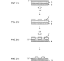
- FIG. BRIEF DESCRIPTION OF THE DRAWINGS It is the schematic which shows the manufacturing method of a flexographic printing plate using the photosensitive resin structure for flexographic printing plates of this embodiment.
- this embodiment an embodiment of the present invention (hereinafter referred to as “this embodiment”) will be described in detail, but the present invention is not limited to this, and various modifications are possible without departing from the gist thereof. is.
- the photosensitive resin composition for a flexographic printing plate of the present embodiment comprises at least a support (a), a photosensitive resin composition layer (b) laminated on the support (a), and the photosensitive resin and an infrared ablative layer (c) laminated on the composition layer (b), wherein the infrared ablative layer (c) contains a resin having a structural unit (c1) represented by the following general formula (1): do.
- R 1 and R 2 each independently represent a nonpolar group
- R 3 and R 4 each independently represent a hydrogen atom and a nonpolar group.
- FIG. 1 shows a schematic cross-sectional view of the photosensitive resin composition for a flexographic printing plate of this embodiment (hereinafter also simply referred to as "this composition").
- This structure comprises a support (a), a photosensitive resin composition layer (b) on which the uneven pattern of the flexographic printing plate is formed, and an infrared ablation layer (c) that functions as a mask when the uneven pattern is formed. It is laminated, and another layer may be provided between each layer as needed. This structure will be described in detail below.
- the support (a) used in this structure is not particularly limited, and examples thereof include polyester films, polyamide films, polyacrylonitrile films, and polyvinyl chloride films.
- polyester film is preferable as the support (a).
- the polyester used for the support (a) is not particularly limited, and examples thereof include polyethylene terephthalate, polybutylene terephthalate, polyethylene naphthalate and the like.
- the thickness of the support (a) is not particularly limited, it is preferably 50 to 300 ⁇ m.
- an adhesive layer may be provided on the support (a) for the purpose of increasing the adhesive strength between the support (a) and the photosensitive resin composition layer (b) described later.
- the adhesive layer is not particularly limited, but includes, for example, the adhesive layer described in WO2004/104701.
- Photosensitive resin composition layer (b) This construct has a photosensitive resin composition layer (b) on a support (a).
- the photosensitive resin composition layer (b) may be directly laminated on the support (a), or may be indirectly laminated via the adhesive layer or the like.
- the photosensitive resin composition layer (b) is not particularly limited, but contains, for example, a thermoplastic elastomer (b-1), preferably an ethylenically unsaturated compound (b-2), a photopolymerization initiator (b -3), it may further contain a liquid diene. Moreover, the photosensitive resin composition layer (b) may further contain an auxiliary additive component, if necessary. Each component will be described in detail below.
- thermoplastic elastomer (b-1) examples include, but are not limited to, copolymers having structural units derived from a monovinyl-substituted aromatic hydrocarbon and structural units derived from a conjugated diene.
- the thermoplastic elastomer (b-1) may further have structural units derived from other monomers. The use of such a thermoplastic elastomer tends to further improve the printing durability of the flexographic printing plate produced using the present composition.
- thermoplastic elastomer (b-1) may be a random copolymer or a block copolymer. and is preferably a block copolymer. The use of such a thermoplastic elastomer tends to further improve the printing durability of the flexographic printing plate produced using the present composition.
- the monovinyl-substituted aromatic hydrocarbon constituting the thermoplastic elastomer (b-1) is not particularly limited, but examples include styrene, t-butylstyrene, 1,1-diphenylethylene, N,N-dimethyl-p- aminoethylstyrene, N,N-diethyl-p-aminoethylstyrene, vinylpyridine, p-methylstyrene, p-methoxystyrene, tertiary butylstyrene, ⁇ -methylstyrene, 1,1-diphenylethylene and the like. . These may be used individually by 1 type, and may be used in combination of 2 or more type.
- styrene is preferable as the monovinyl-substituted aromatic hydrocarbon from the viewpoint that the photosensitive resin composition layer (b) can be smoothly molded at a relatively low temperature.
- the conjugated diene constituting the thermoplastic elastomer (b-1) is not particularly limited, but examples include butadiene, isoprene, 2,3-dimethyl-1,3-butadiene, 2-methyl-1,3-pentadiene, 1 ,3-hexadiene, 4,5-diethyl-1,3-octadiene, 3-butyl-1,3-octadiene, chloroprene and the like. These may be used individually by 1 type, and may be used in combination of 2 or more type.
- butadiene is preferable as the conjugated diene from the viewpoint of the printing durability of the flexographic printing plate produced using this composition.
- the number average molecular weight (Mn) of the thermoplastic elastomer (b-1) is preferably 20,000 or more and 300,000 or less, and 50,000 or more and 200,000 or less, from the viewpoint of viscosity at room temperature. is more preferable.
- the number average molecular weight can be measured by gel permeation chromatography (GPC) and is represented by polystyrene equivalent molecular weight.
- thermoplastic elastomer (b-1) is a block copolymer having a polymer block comprising a monovinyl-substituted aromatic hydrocarbon and a polymer block comprising a conjugated diene
- the thermoplastic elastomer (b-1) is, for example, a linear block copolymer represented by the following general formula group (I) and/or a linear block copolymer or radial block copolymer represented by the following general formula group (II) Including polymers.
- A represents a polymer block composed of monovinyl-substituted aromatic hydrocarbons.
- B represents a polymer block composed of a conjugated diene.
- X is silicon tetrachloride, tin tetrachloride, epoxidized soybean oil, polyhalogenated hydrocarbon compound, carboxylic acid ester compound, polyvinyl compound, bisphenol type epoxy compound, alkoxysilane compound, halogenated silane compound, ester compound, etc.
- a residue of a coupling agent or a residue of a polymerization initiator such as a polyfunctional organolithium compound is shown.
- n, k and m represent integers of 1 or more, for example 1-5.
- the contents of conjugated dienes and monovinyl-substituted aromatic hydrocarbons in the thermoplastic elastomer (b-1) can be measured using a nuclear magnetic resonance spectrometer ( 1 H-NMR).
- 1 H-NMR nuclear magnetic resonance spectrometer
- JNM-LA400 manufactured by JEOL, trade name
- deuterated chloroform is used as the solvent
- the sample concentration is 50 mg/mL
- the observation frequency is 400 MHz
- the chemical Measurement can be performed by using TMS (tetramethylsilane) as a shift reference, setting the pulse delay to 2.904 seconds, the number of scans to 64, the pulse width to 45°, and the measurement temperature to 25°C.
- the copolymerization ratio (mass ratio) between the monovinyl-substituted aromatic hydrocarbon and the conjugated diene is monovinyl Substituted aromatic hydrocarbon/conjugated diene is preferably in the range of 10/80 to 90/20, more preferably in the range of 10/90 to 85/15, and in the range of 10/90 to 60/40. It is even more preferable to have
- thermoplastic elastomer (b-1) may be introduced with other functional groups, chemically modified by hydrogenation or the like, or copolymerized with other components. .
- the content of the thermoplastic elastomer (b-1) in the photosensitive resin composition layer (b) is determined, from the viewpoint of the printing durability of the flexographic printing plate obtained using the present construction, in the photosensitive resin composition layer (
- the total amount of b) is 100% by mass, it is preferably 40% by mass or more, more preferably 40% by mass or more and 80% by mass or less, and further preferably 45% by mass or more and 80% by mass or less. More preferably, it is 45% by mass or more and 75% by mass or less.
- the photosensitive resin composition layer (b) preferably contains the ethylenically unsaturated compound (b-2) as described above.
- the ethylenically unsaturated compound (b-2) is a compound having a radically polymerizable unsaturated double bond.
- Examples of such ethylenically unsaturated compounds (b-2) include, but are not limited to, olefins such as ethylene, propylene, vinyltoluene, styrene, and divinylbenzene; acetylenes; (meth)acrylic acid and/or Unsaturated nitriles such as acrylonitrile; Unsaturated amides such as acrylamide and methacrylamide and derivatives thereof; Unsaturated dicarboxylic acids such as maleic anhydride, maleic acid and fumaric acid and derivatives thereof; Vinyl acetates ; N-vinylpyrrolidone; N-vinylcarbazole; and N-substituted maleimide compounds.
- olefins such as ethylene, propylene, vinyltoluene, styrene, and divinylbenzene
- acetylenes acetylenes
- the ethylenically unsaturated compound (b-2) includes (meth)acrylic acid and/or its Derivatives are preferred.
- Examples of the above derivatives include, but are not limited to, cycloalkyl, bicycloalkyl, cycloalkenyl, bicycloalkenyl, etc. alicyclic compounds; benzyl, phenyl, phenoxy, naphthalene skeleton, anthracene Aromatic compounds having skeleton, biphenyl skeleton, phenanthrene skeleton, fluorene skeleton, etc.; compounds having alkyl group, halogenated alkyl group, alkoxyalkyl group, hydroxyalkyl group, aminoalkyl group, glycidyl group, etc.; alkylene glycol, polyoxyalkylene ester compounds with polyhydric alcohols such as glycol, polyalkylene glycol and trimethylolpropane; and compounds having a polysiloxane structure such as polydimethylsiloxane and polydiethylsiloxane.
- the ethylenically unsaturated compound (b-2) may also be a heteroaromatic compound containing elements such as nitrogen and sulfur.
- the (meth)acrylic acid and/or derivatives thereof are not particularly limited, but examples include diacrylates and dimethacrylates of alkanediols such as hexanediol and nonanediol; ethylene glycol, diethylene glycol, propylene glycol, dipropylene glycol, polyethylene glycol, butylene glycol diacrylates and dimethacrylates; trimethylolpropane tri(meth)acrylate; dimethyloltricyclodecane di(meth)acrylate; isobornyl (meth)acrylate; phenoxypolyethylene glycol (meth)acrylate; meth)acrylate and the like. These may be used individually by 1 type, and may be used in combination of 2 or more types.
- the number average molecular weight (Mn) of the ethylenically unsaturated compound (b-2) is 100 from the viewpoint of improving the nonvolatility of the ethylenically unsaturated compound (b-2) during production and/or storage of the present structure. From the viewpoint of compatibility with other components, it is preferably less than 1000, more preferably 200 or more and 800 or less.
- the content of the ethylenically unsaturated compound (b-2) in the photosensitive resin composition layer (b) is determined from the viewpoint of the printing durability of the flexographic printing plate obtained using the present construction.
- the total amount of (b) is 100% by mass, it is preferably 2% by mass or more and 30% by mass or less, more preferably 2% by mass or more and 25% by mass or less, and 2% by mass or more and 20% by mass or less. is more preferable.
- the photosensitive resin composition layer (b) preferably contains a photopolymerization initiator (b-3).
- the photopolymerization initiator (b-3) is a compound that absorbs light energy and generates radicals. Examples thereof include compounds having a functioning site and a site functioning as a decaying photopolymerization initiator in the same molecule.
- photopolymerization initiator (b-3) examples include, but are not limited to, benzophenone, 4,4-bis(diethylamino)benzophenone, 3,3',4,4'-benzophenonetetracarboxylic acid anhydride. , 3,3′,4,4′-tetramethoxybenzophenone, etc.; anthraquinones, such as t-butylanthraquinone and 2-ethylanthraquinone; 2,4-diethylthioxanthone, isopropylthioxanthone, 2,4-dichlorothioxanthone, etc.
- the photopolymerization initiator (b-3) is preferably a compound having a carbonyl group, such as benzophenones and thioxanthones. Aromatic carbonyl compounds are more preferred.
- the content of the photopolymerization initiator (b-3) in the photosensitive resin composition layer (b) is determined, from the viewpoint of the printing durability of the flexographic printing plate produced using the present construction, in the photosensitive resin composition layer (
- the total amount of b) is 100% by mass, it is preferably 0.1% by mass or more and 10% by mass or less, more preferably 0.1% by mass or more and 5% by mass or less, and 0.5% by mass. It is more preferable that the content is not less than 5% by mass or less.
- the photosensitive resin composition layer (b) preferably contains a liquid diene.
- a liquid diene is a compound having a liquid carbon-carbon double bond.
- the "liquid state" of the "liquid diene” means a property of being easily flow-deformed and capable of being solidified into the deformed shape by cooling.
- a liquid diene has elastomeric properties such that when an external force is applied, it instantly deforms in response to the external force, and recovers its original shape in a short period of time when the external force is removed.
- the liquid diene is not particularly limited, but examples include liquid polybutadiene, liquid polyisoprene, modified liquid polybutadiene, modified liquid polyisoprene, liquid acrylonitrile-butadiene copolymer, and liquid styrene-butadiene copolymer. mentioned.
- the liquid diene is a copolymer having a diene content of 50% by mass or more.
- liquid polybutadiene is preferable as the liquid diene from the viewpoint of the mechanical properties of the present composition and the flexographic printing plate using the same.
- the 1,2-vinyl bond content of the liquid diene is preferably 1% or more and 80% or less from the viewpoint of making the hardness of the present structure and the flexographic printing plate using the same appropriate, 5% or more and 70% or less is more preferable, and 5% or more and 65% or less is even more preferable.
- 1,2-vinyl bond amount means that 1 , the ratio of those incorporated by 2-bonds.
- the amount of 1,2-vinyl bonds can be obtained from the peak ratio of 1 H-NMR (magnetic resonance spectrum) of liquid polybutadiene.
- 1,2-polybutadiene which is a liquid polybutadiene having a 1,2-vinyl bond, has a vinyl double bond as a side chain, so the reactivity of radical polymerization is high, and the photosensitive resin composition layer It is preferable from the viewpoint of increasing the hardness of (b).
- Liquid polybutadiene is usually a mixture of 1,2-polybutadiene having 1,2-vinyl bonds and 1,4-polybutadiene having 1,4-vinyl bonds. Incorporating 1,4-polybutadiene into the liquid diene is effective in improving the flexibility of the flexographic printing plate.
- 1,4-polybutadiene includes cis-type 1,4-polybutadiene and trans-type 1,4-polybutadiene.
- 1,4-Polybutadiene, both cis-type and trans-type has a vinyl group that is a double bond inside, so it has low reactivity in radical polymerization and can form a flexible resin. .
- the average value is used as the 1,2-vinyl bond amount.
- a liquid polybutadiene having a 1,2-vinyl bond content of 10% or less and a liquid polybutadiene having a 1,2-vinyl bond content of 80% or more are used. It is preferable to adjust the total amount of 1,2-vinyl bonds by mixing with polybutadiene. More preferably, a liquid polybutadiene having a 1,2-vinyl bond content of 5% or less and a liquid polybutadiene having a 1,2-vinyl bond content of 80% or more are mixed to adjust the total 1,2-vinyl bond content. preferably.
- the number average molecular weight of the liquid diene is not particularly limited as long as it is liquid at 20° C., but is preferably 500 or more from the viewpoint of the printing durability and handleability of the flexographic printing plate obtained using this composition. It is 60,000 or less, more preferably 500 or more and 50,000 or less, and still more preferably 800 or more and 50,000 or less.
- the content of the liquid diene in the photosensitive resin composition layer (b) is set so that the total amount of the photosensitive resin composition layer (b) is 100 mass from the viewpoint of the printing durability of the present structure and the flexographic printing plate using the same. %, preferably 10% by mass or more and 40% by mass or less, more preferably 15% by mass or more and 40% by mass or less, and even more preferably 20% by mass or more and 40% by mass or less.
- the auxiliary additive component is not particularly limited, but includes, for example, a polar group-containing polymer, a plasticizer other than a liquid diene, a thermal polymerization inhibitor other than a stabilizer, an antioxidant, an ultraviolet absorber, a dye/pigment, and the like.
- the polar group-containing polymer is not particularly limited. polymers. More specifically, a carboxyl group-containing acrylonitrile-butadiene rubber, a carboxyl group-containing styrene-butadiene rubber, a polymer of an aliphatic conjugated diene containing a carboxyl group, a phosphoric acid group, or an emulsification of an ethylenically unsaturated compound having a carboxyl group Examples include polymers, sulfonic acid group-containing polyurethanes, and carboxyl group-containing butadiene latexes. These polar group-containing polymers may be used alone or in combination of two or more.
- carboxyl group-containing butadiene latex is preferable as the polar group-containing polymer from the viewpoint of obtaining high resolution in the flexographic printing plate using this composition.
- Plasticizers other than liquid dienes are not particularly limited. Examples include hydrocarbon oils such as naphthenic oil and paraffin oil; liquid dienes such as liquid acrylonitrile-butadiene copolymers and liquid styrene-butadiene copolymers. polystyrene having a number average molecular weight of 2000 or less; ester plasticizers such as sebacate and phthalate. These other plasticizers may have hydroxyl groups or carboxyl groups. Further, these other plasticizers may be provided with a photopolymerizable reactive group such as a (meth)acryloyl group. Other plasticizers may be used alone or in combination of two or more.
- thermal polymerization inhibitor and antioxidant those commonly used in the field of resin materials or rubber materials can be used. Specifically, phenol-based materials are mentioned.
- phenolic materials include, but are not limited to, vitamin E, tetrakis-(methylene-3-(3′,5′-di-t-butyl-4′-hydroxyphenyl)propionate)methane, 2,5-di-t-butyl hydroquinone, 2,6-di-t-butyl-p-cresol, 2-t-butyl-6-(3-t-butyl-2-hydroxy-5-methylbenzyl)- 4-methylphenyl acrylate and the like.
- the thermal polymerization inhibitor and the antioxidant may be used alone or in combination of two or more.
- the ultraviolet absorber is not particularly limited, but includes, for example, known benzophenone-based compounds, salicylate-based compounds, acrylonitrile-based compounds, metal complex-based compounds, and hindered amine-based compounds. Dyes and pigments shown below may also be used as the ultraviolet absorber.
- ultraviolet absorbers examples include, but are not particularly limited to, 2-ethoxy-2'-ethyloxalic acid bisanilide, 2,2'-dihydroxy-4-methoxybenzophenone, and the like.
- Dyes and pigments are effective as coloring means for improving visibility.
- Dyes are not particularly limited, but examples include water-soluble basic dyes, acid dyes, direct dyes, and water-insoluble sulfur dyes, oil-soluble dyes, disperse dyes, and the like.
- Anthraquinone dyes, indigoid dyes, and azo dyes are particularly preferred, and azo oil-soluble dyes and the like are more preferred.
- the pigment is not particularly limited, but includes, for example, natural pigments, synthetic inorganic pigments, synthetic organic pigments, and the like.
- Synthetic organic pigments include azo-based pigments, triphenylmethane-based pigments, quinoline-based pigments, anthraquinone-based pigments, and phthalocyanine-based pigments.
- the total amount of the auxiliary additive components described above is preferably 0% by mass or more and 10% by mass or less, and 0% by mass or more and 5% by mass or less when the total amount of the photosensitive resin composition layer (b) is 100% by mass. It is more preferably 0% by mass or more and 3% by mass or less.
- an infrared ablation layer (c) is laminated on the photosensitive resin composition layer (b) described above.
- the infrared ablation layer (c) contains a predetermined resin, is ablationable with an infrared laser, and functions as a layer for shielding light rays other than infrared rays.
- high sensitivity to laser means that when drawing is performed with the same laser energy, the volume to be ablated is larger, especially in the depth direction.
- the infrared ablation layer instantaneously reaches a high temperature of several hundred degrees due to infrared irradiation. At that time, if the resin is easy to depolymerize, decomposition of the main chain in the resin will occur efficiently even if the ablation is for a short period of time. On the other hand, in the case of a resin that is difficult to depolymerize, for example, a resin having a polar group in the side chain, only the side chain is decomposed during ablation, and the main chain is less likely to be cut. Therefore, the resin remains in the infrared ablation layer even after infrared irradiation.
- Resins obtained by condensation polymerization are known to undergo cleavage of the main chain after formation of a ring structure during decomposition.
- infrared ablation which is heat treatment in a short period of time, does not easily reduce the molecular weight, resulting in poor laser sensitivity.
- the infrared ablation layer (c) contains a resin that is easily depolymerized.
- cleavage of the main chain tends to initiate from thermally unstable portions such as branches present in the polymer.
- the side chain corresponding to the branch has polarity, the decomposition of the side chain tends to predominantly occur, and the main chain is less likely to break, which is not preferable.
- the side chains of the resin contained in the infrared ablation layer (c) are non-polar groups.
- the contribution of intramolecular or intermolecular chain transfer cannot be ignored when main chain cleavage proceeds. Therefore, it is better not to have a tertiary hydrogen that is easily abstracted by chain transfer. That is, it is important that the portion corresponding to the plane of symmetry of branching is also a non-polar group.
- the resin contained in the infrared ablation layer (c) of the present embodiment has a structural unit (c1) containing a quaternary carbon atom to which two nonpolar groups are bonded, as represented by the following general formula (1). However, if necessary, it may have other structural units. (Here, in formula (1), R 1 and R 2 each independently represent a nonpolar group, and R 3 and R 4 each independently represent a hydrogen atom and a nonpolar group.)
- monomer means a compound before polymerization
- structural unit means a predetermined repeating unit formed by polymerizing a monomer
- the nonpolar group in general formula (1) is not particularly limited as long as it is a group composed of carbon atoms and/or silicon atoms and hydrogen atoms. Examples include alkyl groups, aryl groups, cycloalkyl groups, and phenyl groups. , an alkenyl group, an aralkyl group, a cycloalkenyl group, an alkynyl group, a silyl group, a siloxanyl group, and the like. In addition, a hydrogen atom is not included in the non-polar group.
- the groups represented by R 1 , R 2 , R 3 and R 4 are preferably alkyl groups and phenyl groups.
- the indicated group is an alkyl group or a phenyl group
- the nonpolar groups of R 3 and R 4 are an alkyl group or a phenyl group
- the groups indicated by R 1 and R 2 are an alkyl group or a phenyl group.
- R 3 and R 4 are more preferably hydrogen atoms. This tends to further improve developability with a solvent-based developer, which will be described later.
- the dispersibility of carbon black which will be described later, tends to be further improved, and the developability with an aqueous developer tends to be further improved.
- the group represented by R 1 is preferably an alkyl group, a phenyl group, or an acyl group.
- the number of carbon atoms in the nonpolar group is preferably 1 or more and 20 or less, more preferably 1 or more and 10 or less, and still more preferably 1 or more and 5 or less.
- Monomers satisfying the general formula (1) are not particularly limited, but examples include isobutylene, 2-methyl-2-butene, 2,3dimethyl-2-butene, and other substituted with an alkyl group of, modified products thereof; ⁇ -methylstyrene, cis-(1-methyl-1-propenyl)benzene, trans-(1-methyl-1-propenyl)benzene, and these methyl groups
- Examples include those substituted with other alkyl groups such as ethyl groups, modified products thereof; 1,1-diphenylethylene and the like.
- the structural unit (c1) in the resin not only does the resin alone have excellent developability in a solvent-based developer, but the highly polar carbon black described later can be dispersed while maintaining high dispersibility. It is thus possible to exhibit high developability with an aqueous developer.
- R 3 and R 4 in general formula (1) are a hydrogen atom, an alkyl group, an aryl group, a cycloalkyl group, a phenyl group, an alkenyl group, an aralkyl group, a cycloalkenyl group, an alkynyl group, a silyl group, and a siloxanyl group; are preferred, and both are more preferably hydrogen atoms.
- the depolymerization property of the resin is further improved, so that the laser sensitivity of the infrared ablative layer (c) tends to be further improved.
- the developability with a solvent-based developer is further improved, and the dispersibility of carbon black is further improved, so that the developability with an aqueous developer tends to be further improved.
- isobutylene, ⁇ -methylstyrene, and those in which the methyl group is replaced with another alkyl group such as an ethyl group can be mentioned as those satisfying such a constitution.
- the use of a monomer having a phenyl group such as ⁇ -methylstyrene tends to further improve the pinhole resistance of the infrared ablation layer (c).
- the use of such a monomer tends to further improve the developability with water-based developers and solvent-based developers.
- R 1 and R 2 each independently represent an alkyl group, an aryl group, a cycloalkyl group, a phenyl group, an alkenyl group, an aralkyl group, a cycloalkenyl group, an alkynyl group, a silyl group, and a siloxanyl group. is preferred, an alkyl group and a phenyl group are more preferred, and each independently an alkyl group is further preferred. Rubber-like elasticity can be obtained by R 1 and/or R 2 being an alkyl group. Therefore, it can become a soft portion in the elastomer, and tends to further improve the flexibility of the infrared ablative layer (c). In addition, since R 1 and/or R 2 are phenyl groups, the composition tends to be molded smoothly at a relatively low temperature.
- the structural unit (c1) may be used singly or in combination of two or more.
- the above resin may contain, as the structural unit (c1), a structural unit in which R 1 and R 2 are alkyl groups, and a structural unit in which one of R 1 and R 2 is an alkyl group and the other is a phenyl group. may have This can improve the properties of both the alkyl group and the phenyl group.
- isobutylene and those in which the methyl group thereof is substituted with another alkyl group such as an ethyl group can be mentioned as those satisfying such a constitution.
- the content of the structural unit (c1) is preferably 40% by mass or more, more preferably 50% by mass or more, still more preferably 60% by mass or more, based on the total amount of the resin. It is preferably 70% by mass or more, and more preferably 80% by mass or more. In addition, the content of the structural unit (c1) is preferably 100% by mass or less, more preferably 95% by mass or less, still more preferably 90% by mass or less, based on the total amount of the resin. It is preferably 85% by mass or less, and more preferably 80% by mass or less. Upper and lower limits of these numerical values can be combined arbitrarily.
- the content of the structural unit (c1) is 40% by mass or more, the laser sensitivity and flexibility of the infrared ablation layer (c) tend to be further improved. Moreover, when the content of the structural unit (c1) is 100% by mass or less, the resistance to pinholes of the infrared ablation layer (c) tends to be further improved.
- the content of the structural unit (c1) is within the above range, the developability in the solvent-based developer is further improved, and the dispersibility of carbon black is further improved, so that the content in the aqueous developer is improved. Developability tends to be further improved.
- the resin used in the infrared ablative layer (c) preferably contains a structural unit (c2) containing an aromatic group in its side chain, apart from the structural unit (c1).
- a structural unit (c2) a structural unit (c2) derived from a monovinyl-substituted aromatic hydrocarbon is preferred.
- the monovinyl aromatic hydrocarbon may be chemically bonded to the monomer represented by the general formula (1), or may be added as a separate resin. From the viewpoint of the above, it is preferable that they are chemically bonded to form a copolymer.
- the resin contains the structural unit (c2) derived from a monovinyl-substituted aromatic hydrocarbon, the pinhole resistance tends to be further improved.
- Examples of monovinyl aromatic hydrocarbon compounds include, but are not limited to, styrene, t-butylstyrene, N,N-dimethyl-p-aminoethylstyrene, N,N-diethyl-p-aminoethylstyrene, vinylpyridine, Examples include monomers such as p-methylstyrene and tertiary butylstyrene. Among these, styrene is preferable because the structure can be molded smoothly at a relatively low temperature.
- the structural unit (c2) may be used alone or in combination of two or more.
- the content of the structural unit (c2) is preferably 0% by mass or more, more preferably 5% by mass or more, still more preferably 10% by mass or more, and still more preferably It is 15% by mass or more, and more preferably 20% by mass or more.
- the content of the structural unit (c2) is preferably 60% by mass or less, more preferably 55% by mass or less, still more preferably 50% by mass or less, based on the total amount of the resin. It is preferably 45% by mass or less, and more preferably 40% by mass or less. Upper and lower limits of these numerical values can be combined arbitrarily.
- the content of the structural unit (c2) is 0% by mass or more, the resistance to pinholes of the infrared ablation layer (c) tends to be further improved. Further, when the content of the structural unit (c2) is 60% by mass or less, the laser sensitivity and flexibility of the infrared ablative layer (c) tend to be further improved.
- “0% by mass or more” includes both a mode containing the structural unit (c2) and a mode not containing the structural unit (c2). Upper and lower limits of these numerical values can be combined arbitrarily.
- the contents and ratios of the structural units (c1) and (c2) in the resin used in the infrared ablation layer (c) can be measured using a nuclear magnetic resonance spectrometer ( 1 H-NMR).
- the infrared ablation layer (c) may contain other resins besides the above resins.
- the content of the resin is preferably 50% by mass or more, more preferably 70% by mass or more and 100% by mass or less, based on the total resin components of the infrared ablative layer (c).
- the content of the resin is within the above range, the laser sensitivity and flexibility of the infrared ablative layer (c) tend to be further improved.
- a resin having a polar group in a side chain it is preferable that the above resin is contained in an amount of 70% or more in all resin components from the viewpoint of laser sensitivity.
- the content of the resin is preferably 20% by mass or more, more preferably 30% by mass or more, and even more preferably 40% by mass or more, relative to the total amount of the infrared ablative layer (c). .
- the content of the resin is preferably 90% by mass or less, more preferably 80% by mass or less, and preferably 70% by mass or less, relative to the total amount of the infrared ablation layer (c). More preferred. Upper and lower limits of these numerical values can be combined arbitrarily.
- the content of the resin is 20% by mass or more, the resistance to pinholes and flexibility of the infrared ablation layer (c) tend to be further improved. Further, when the content of the resin is 90% by mass or less, the laser sensitivity and shielding properties of the infrared ablation layer (c) tend to be further improved.
- the content of the resin is within the above range, the developability in a solvent-based developer and an aqueous developer and the dispersibility of carbon black tend to be further improved.
- the infrared-ablable layer (c) may contain an infrared-absorbing substance for performing an ablation process.
- an infrared-absorbing substance for performing an ablation process.
- the infrared absorbing substance a single substance or a compound having strong absorption in the range of 750 to 2000 nm is usually used.
- infrared absorbing substances include, but are not limited to, inorganic pigments such as carbon black, graphite, copper chromite, and chromium oxide; pigments such as polyphthalocyanine compounds, cyanine pigments, and metal thiolate pigments. be done.
- inorganic pigments such as carbon black, graphite, copper chromite, and chromium oxide
- pigments such as polyphthalocyanine compounds, cyanine pigments, and metal thiolate pigments. be done.
- Carbon black in particular, can be used in a wide range of particle sizes from 13 nm to 85 nm, and is therefore preferable as an infrared absorbing substance.
- Carbon black can also function as a shielding substance described below.
- the infrared ablative layer (c) plays a role as a mask, it may contain a shielding substance against non-infrared rays such as ultraviolet rays.
- a substance that reflects or absorbs ultraviolet light can be used as the shielding substance against non-infrared rays. UV absorbers, carbon black, graphite and the like can be mentioned.
- the total content of the infrared absorbing substance and the shielding substance is preferably 10% by mass or more and 80% by mass or less, preferably 20% by mass or more and 70% by mass or less, relative to the total amount of the infrared ablation layer (c), It is preferably 30% by mass or more and 60% by mass or less.
- the total content of the infrared absorbing substance and the shielding substance is within the above range, laser sensitivity and shielding properties tend to be further improved.
- the infrared ablation layer (c) is excellent for both solvent-based developers and water-based developers. It has been found that the developability is improved.
- the infrared ablative layer (c) of the present embodiment preferably contains carbon black as an infrared absorbing material for performing ablation processing and as a non-infrared shielding material for serving as a mask.
- the pH of carbon black is preferably 2.0 or more and 5.5 or less.
- Low pH carbon black is in a state in which a large number of functional groups are introduced on its surface, and is more hydrophilic than ordinary carbon black. This makes it possible to exhibit excellent developability particularly with respect to an aqueous developer.
- the pH of carbon black is more preferably 2.5 or more and 5.0 or less, more preferably 2.5 or more and 4.5 or less.
- the pH of carbon black is a value measured with a glass electrode pH meter after preparing a mixture of carbon black and distilled water according to ASTM D1512.
- Carbon black is classified into, for example, furnace black, channel black, thermal black, acetylene black, lamp black, etc., depending on the method of production thereof, but furnace black is preferred in order to obtain the desired properties.
- Furnace black is a method of obtaining carbon black by injecting petroleum- or coal-based oil into high-temperature gas as a raw material for incomplete combustion, and can be produced using a widely known method.
- Carbon black that has been conventionally used to form a black matrix can be used as long as it satisfies the above requirements.
- Specific examples include MA7, MA8, MA11, MA14, MA77, MA100, MA100R, MA100S, MA220, MA230, #970, #1000, #2350, #2360 manufactured by Mitsubishi Chemical, Toka Black #8300 manufactured by Tokai Carbon, etc. is mentioned.
- the film thickness of the infrared ablation layer (c) of this construction is preferably thick from the viewpoint of ensuring the light shielding property against ultraviolet rays in the process of exposing the photosensitive resin construction for printing plates. From the viewpoint of increasing the strength, the thinner the better.
- the content of carbon black is preferably 10% by mass or more and 70% by mass or less, more preferably 20% by mass or more and 60% by mass or less, and still more preferably 30% by mass, based on the total amount of the infrared ablative layer (c). It is more than mass % and below 50 mass %. When the content of carbon black is within the above range, laser sensitivity and shielding properties tend to be further improved.
- the compounding ratio of the resin and carbon black (resin/carbon black) in the infrared ablation layer (c) is preferably in the range of 80/20 to 50/50, more preferably 75/25 to 55/45. range, more preferably 70/30 to 60/40.
- the compounding ratio (resin/carbon black) is within the above range, laser sensitivity and shielding properties tend to be further improved.
- the infrared ablative layer (c) preferably contains a dispersant for the purpose of assisting the dispersibility of carbon black.
- the dispersant is preferably a compound having an adsorption portion capable of interacting with the surface functional group of the infrared absorbent and a resin-compatible portion compatible with the binder polymer.
- the adsorption portion of the dispersant is not particularly limited, but examples include amino groups, amide groups, urethane groups, carboxyl groups, carbonyl groups, sulfone groups, and nitro groups. Among these, an amino group, an amide group, and a urethane group are preferable.
- the resin-compatible part is not particularly limited, but examples include saturated alkyl, unsaturated alkyl, polyether, polyester, poly(meth)acryl, and polyol.
- the solubility parameter (SP value) of the dispersant is preferably 9.5 or more and 12.5 or less, more preferably 10.0 or more and 12.0 or less.
- SP value The solubility parameter (SP value) is within the above range, the dispersibility of carbon black is further improved, and the developability with an aqueous developer tends to be further improved.
- V is the molar molecular volume of the solvent
- ⁇ E is the cohesion energy (evaporation energy).
- the molar molecular volume and cohesive energy of the solvent can also be determined from known values, such as the document "POLYMER ENGINEERING AND SCIENCE, Vol. 14, 147-154, 1974".
- solubility parameter SP value
- a poor solvent with a lower SP value than the good solvent is added dropwise to a solution in which a sample with an unknown SP value is dissolved in a good solvent with a known SP value, and the solute begins to precipitate. Measure the volume of the anti-solvent.
- a poor solvent with a higher SP value than the good solvent is added dropwise to a solution in which a newly prepared sample with an unknown SP value is dissolved in a good solvent with a known SP value, and the solute begins to precipitate. Measure the volume of the anti-solvent. It can be obtained by applying the volume of each poor solvent obtained here to the following formula (2).
- Vml is the volume of a poor solvent with a low SP value
- V mh is the volume of a poor solvent with a high SP value
- ⁇ ml is the SP value of a poor solvent with a low SP value
- ⁇ mh is a poor solvent with a high SP value.
- the content of the dispersing agent in the infrared ablative layer (c) of the present embodiment is within a range that can ensure the strength of the infrared ablative layer (c) while uniformly dispersing the infrared absorber in the infrared ablative layer (c). It is preferred to select and add. If the content of the dispersing agent is too small, the infrared absorbing agent cannot be sufficiently dispersed in the infrared ablative layer (c). .
- the content of the dispersant is preferably 0.1% by mass or more and 50% by mass or less, more preferably 1% by mass or more and 30% by mass or less, relative to the entire infrared ablation layer (c). It is more preferably 3% by mass or more and 20% by mass or less.
- the content of the dispersant is preferably 0.5 parts by mass or more with respect to 100 parts by mass of carbon black, and 1 part by mass or more. It is more preferable that the amount is 3 parts by mass or more. From the viewpoint of the film strength of the infrared ablation layer, the content of the dispersant is preferably 50 parts by mass or less, more preferably 30 parts by mass or less, with respect to 100 parts by mass of carbon black. It is more preferably not more than parts by mass.
- the dispersant in the infrared ablative layer (c) preferably has a branched structure.
- high dispersibility can be obtained because the dispersant has low crystallinity.
- the weight average molecular weight of the dispersant in the infrared ablation layer (c) of the present embodiment is preferably selected within a range in which the dispersant does not bleed out while uniformly dispersing the infrared absorbent in the infrared ablation layer.
- the dispersing agent When the dispersing agent bleeds out, it cannot interact with the infrared absorbing agent, such as carbon black, resulting in poor dispersion and heavy peeling.
- the weight average molecular weight of the dispersant measured in terms of standard polystyrene by gel permeation column chromatography is preferably 1000 or more and 10000 or less, more preferably 2000 or more and 7000 or less, and 2500 or more and 5000 or less. More preferred.
- the film thickness of the infrared ablation layer (c) of this structure is preferably thick from the viewpoint of ensuring the shielding property against ultraviolet rays in the step of performing exposure processing on this structure, and from the viewpoint of increasing the ablation property. Thinner is better.
- the thickness of the infrared ablation layer (c) is preferably 0.1 ⁇ m or more and 20 ⁇ m or less, more preferably 0.5 ⁇ m or more and 15 ⁇ m or less, and even more preferably 1.0 ⁇ m or more and 10 ⁇ m or less.
- the optical density of the infrared ablation layer (c) is preferably 2 or more, more preferably 3 or more.
- the optical density can be measured using a D200-II transmission densitometer (manufactured by GretagMacbeth). Also, the optical density is the so-called visual sensitivity (ISO visual), and the light to be measured is in the wavelength range of about 400 to 750 nm.
- ISO visual visual sensitivity
- the method for forming the infrared ablation layer (c) is not particularly limited.
- a resin solution is prepared using a predetermined solvent.
- carbon black and a dispersant are added thereto, the carbon black is dispersed in the resin solution, and then coated on a cover film such as a polyester film, and then the cover film is used as a photosensitive resin composition layer.
- a cover film such as a polyester film
- the cover film is used as a photosensitive resin composition layer.
- a method for dispersing carbon black in a resin solution it is effective to use both forced stirring with a stirring blade and stirring using ultrasonic waves and various mills.
- a method of pre-kneading a resin, carbon black and a dispersant using an extruder or a kneader and then dissolving the mixture in a solvent is also effective for obtaining good dispersibility of carbon black.
- carbon black may be forcibly dispersed in the resin in the form of a latex solution.
- Solvents such as solutions and dispersions for forming the infrared ablation layer (c) can be appropriately selected in consideration of the solubility of the resin and infrared absorber used. Only one kind of solvent may be used, or two or more kinds of solvents may be mixed and used.
- the infrared ablation layer (c) it is effective to improve the film quality of the infrared ablation layer (c) by mixing a solvent with a relatively low boiling point and a solvent with a high boiling point to control the volatilization speed of the solvent.
- Solvents for forming the infrared ablative layer (c) are not particularly limited, but examples include toluene, xylene, cyclohexane, methyl acetate, ethyl acetate, propyl acetate, butyl acetate, amyl acetate, methyl ethyl ketone, acetone, cyclohexanone, Ethylene glycol, propylene glycol, ethanol, water, propylene glycol monomethyl ether, propylene glycol monomethyl ether acetate, dimethylacetamide, dimethylformamide, n-propyl alcohol, i-propyl alcohol, 1,4-dioxane, tetrahydrofuran, diethyl ether, n- Hexane, n-heptane, n-pentane, acetonitrile, analogues thereof and the like can be mentioned.
- the cover film for forming the infrared ablation layer (c) of this structure is preferably a film with excellent dimensional stability, such as polyethylene terephthalate film.
- the cover film may be used in an untreated state, but if necessary, it may be used with functions such as release treatment and antistatic treatment.
- This construct may further have one or more intermediate layers (d) between the photosensitive resin composition layer (b) and the infrared ablative layer (c).
- the intermediate layer (d) is not particularly limited, but can be, for example, an oxygen inhibiting layer, an adhesive layer and/or a protective layer. Each layer will be described below.
- the intermediate layer (d) is preferably an oxygen-blocking layer having oxygen-blocking ability.
- the photosensitive resin composition layer (b) When the photosensitive resin composition layer (b) is cured by irradiation with ultraviolet rays, curing proceeds by radical polymerization. If oxygen coexists during this radical polymerization, the radical-generating compound reacts with oxygen to suppress the polymerization reaction. When the polymerization reaction is inhibited in this way, there is a possibility that unreacted portions remain in the exposed areas of the photosensitive resin composition layer (b). Since this unreacted portion is removed in the fourth step, which will be described later, the pattern finally formed on the flexographic printing plate has a curved portion at the tip. This is because the portion of the photosensitive resin composition layer (b) on the infrared ablation layer (c) side is particularly susceptible to polymerization inhibition by oxygen, and the photosensitive resin composition layer ( This is because unreacted portions tend to occur in b).
- the intermediate layer (d) has an oxygen inhibiting ability to reduce the amount of oxygen in contact with the photosensitive resin composition layer (b). .
- the intermediate layer (d) may be an adhesive layer that improves the adhesion between the photosensitive resin composition layer (b) and the infrared ablation layer (c). This tends to improve handleability.
- the intermediate layer (d) may also have the function of protecting the infrared ablation layer (c).
- the infrared ablative layer (c) laminated with the cover film is transported, the infrared ablative layer (c) comes into contact with the roll, and tight winding occurs during transport of the film roll. In the roll, the infrared ablative layer (c) and the cover film laminated thereon may rub against each other. As a result, the infrared ablation layer (c) may be physically chipped and pinholes may occur.
- the intermediate layer (d) constituting the structure preferably has physical strength and heat resistance as a protective layer.
- the method for producing a flexographic printing plate of the present embodiment includes, using the present structure, a first step of irradiating ultraviolet rays from the support (a) side, and irradiating the infrared ablation layer (c) with infrared rays. A second step of drawing a pattern, and a third step of pattern exposure by irradiating the photosensitive resin composition layer (b) with ultraviolet rays using the pattern-drawn infrared ablation layer (c) as a mask. and a fourth step of removing the infrared ablation layer (c) and the unexposed portion of the photosensitive resin composition layer (b).
- a step of post-exposure treatment is performed as necessary, and a flexographic printing plate (letterpress printing plate) is obtained from the cured product of the photosensitive resin composition layer.
- the surface of the flexographic printing plate may be brought into contact with a liquid containing a silicone compound and/or a fluorine compound.
- the method of irradiating the photosensitive resin composition layer (b) with ultraviolet rays from the support (a) side is not particularly limited, and a known irradiation unit can be used.
- the wavelength of the ultraviolet rays irradiated at this time is preferably 150 to 500 nm, more preferably 300 to 400 nm.
- the ultraviolet light source is not particularly limited, but for example, low-pressure mercury lamps, high-pressure mercury lamps, ultra-high-pressure mercury lamps, metal halide lamps, xenon lamps, zirconium lamps, carbon arc lamps, fluorescent lamps for ultraviolet rays, etc. can be used.
- this first step may be performed before or after the second step, which will be described later.
- the method of drawing a pattern by irradiating the infrared ablation layer (c) with infrared rays is not particularly limited, and a known irradiation unit can be used.
- the irradiation of the infrared rays to the infrared ablation layer (c) can be performed from the infrared ablation layer (c) side.
- this structure has a cover film
- the cover film is first peeled off before infrared irradiation. Thereafter, the infrared ablation layer (c) is pattern-irradiated with infrared rays to decompose the resin in the infrared-irradiated portions, and the pattern is drawn. Thereby, a mask for the infrared ablation layer (c) can be formed on the photosensitive resin composition layer (b).
- suitable infrared lasers include, for example, ND/YAG lasers (eg, 1064 nm) or diode lasers (eg, 830 nm).
- Laser systems suitable for CTP plate making technology are commercially available, for example the diode laser system CDI Spark (ESKO GRAPHICS) can be used.
- the laser system includes a rotating cylindrical drum that holds the structure, an IR laser illumination device, and a layout computer, with image information transmitted directly from the layout computer to the laser device.
- the patterned infrared ablation layer (c) is used as a mask to irradiate the photosensitive resin composition layer (b) with ultraviolet rays for pattern exposure.
- the light passing through the mask accelerates the curing reaction of the photosensitive resin composition layer (b), and the pattern formed on the infrared ablation layer (c) reverses the unevenness, thereby forming the photosensitive resin composition layer.
- the ultraviolet irradiation may be applied to the entire surface of the structure.
- the third step can be performed with this structure attached to the laser cylinder, but generally, this structure is removed from the laser device and irradiated using a conventional irradiation unit.
- a conventional irradiation unit the same units as those exemplified for the ultraviolet irradiation in the first step can be used.
- the fourth step is to remove the infrared ablation layer (b) and the unexposed portions of the photosensitive resin composition layer (c).
- the removal method is not particularly limited, and conventionally known methods can be applied.
- the photosensitive resin composition layer (b) of this structure is exposed, and then the unexposed portion is washed away with a solvent for solvent development or a washing liquid for water development, or 40 C. to 200.degree. C., the unexposed portion is removed by bringing it into contact with a predetermined absorbing layer capable of absorption, and removing the absorbing layer.
- a flexographic printing plate is manufactured by post-exposure processing as necessary.
- an intermediate layer (d) is provided between the infrared ablation layer (c) and the photosensitive resin composition layer (b), it may be removed simultaneously in the development step.
- the developing solvent used for solvent development of the unexposed area is not particularly limited, but examples thereof include esters such as heptyl acetate and 3-methoxybutyl acetate; hydrocarbons such as petroleum fractions, toluene and decalin. and mixtures of alcohols such as propanol, butanol, and pentanol with chlorinated organic solvents such as tetrachlorethylene.
- esters such as heptyl acetate and 3-methoxybutyl acetate
- hydrocarbons such as petroleum fractions, toluene and decalin.
- mixtures of alcohols such as propanol, butanol, and pentanol with chlorinated organic solvents such as tetrachlorethylene.
- water an alkaline aqueous solution, a neutral detergent, and a surfactant can be suitably used as the washing liquid for water development.
- surfactants examples include anionic surfactants, amphoteric surfactants, and nonionic surfactants. These may be used individually by 1 type, and may be used in mixture of 2 or more types.
- anionic surfactants include, but are not limited to, sulfates, higher alcohol sulfates, higher alkyl ether sulfates, sulfated olefins, alkylbenzenesulfonates, ⁇ -olefinsulfonates, and phosphates. salts, dithiophosphate salts, and the like.
- amphoteric surfactant is not particularly limited, but includes, for example, an amino acid type amphoteric surfactant, a betaine type amphoteric surfactant and the like.
- nonionic surfactants include, but are not limited to, higher alcohol ethylene oxide adducts, alkylphenol ethylene oxide adducts, fatty acid ethylene oxide adducts, polyhydric alcohol fatty acid ester ethylene oxide adducts, and higher alkylamine ethylene oxide adducts.
- Polyethylene glycol type surfactants such as fatty acid amide ethylene oxide adducts, polypropylene glycol ethylene oxide adducts, glycerol fatty acid esters, pentaerythritol fatty acid esters, sorbitol and sorbitan fatty acid esters, alkyl esters of polyhydric alcohols, alkanolamines and polyhydric alcohol surfactants such as fatty acid amides of the type.
- a pH adjuster may be used for the alkaline aqueous solution.
- the pH adjuster may be either an organic material or an inorganic material, but is preferably one that can adjust the pH to 9 or higher.
- Examples of pH adjusters include, but are not limited to, sodium hydroxide, sodium carbonate, potassium carbonate, sodium silicate, sodium metasilicate, sodium succinate and the like.
- the heat-developable absorption layer is not particularly limited, but examples thereof include non-woven fabric materials, paper materials, fiber fabrics, open-cell foams, and porous materials. Among these, nonwoven materials made of nylon, polyester, polypropylene, polyethylene, and combinations of these nonwoven materials are preferred, and nonwoven continuous webs of nylon or polyester are more preferred.
- the flexographic printing method of the present embodiment comprises a first step of irradiating ultraviolet rays from the support (a) side using the above-described photosensitive resin composition for flexographic printing plates, and irradiating the infrared ablation layer (c) with infrared rays. and a third step of pattern exposure by irradiating the photosensitive resin composition layer (b) with ultraviolet rays using the pattern-drawn infrared ablation layer (c) as a mask.
- the first to fourth steps in the flexographic printing method are as described above.
- a fifth step is a step of printing using the flexographic printing plate obtained by the first to fourth steps.
- the printing method using the flexographic printing plate is not particularly limited as long as it is a method of applying ink to the raised portions of the flexographic printing plate and transferring the ink to the substrate.
- Tufprene A manufactured by Asahi Kasei, styrene-butadiene-styrene block copolymer 60 parts by weight
- B-2000 manufactured by Nippon Petrochemicals, liquid polybutadiene
- 1,9-nonanediol diacrylate 7 parts by weight 2 , 2-dimethoxy-2-phenylacetophenone and 0.3 parts by mass of 2,6-di-t-butyl-p-cresol were kneaded with a pressure kneader to prepare a photosensitive resin composition.
- the photosensitive resin composition is put into an extrusion molding machine, and a support (polyethylene terephthalate film) is attached to one side of the photosensitive resin composition layer extruded from the T-shaped die to form a photosensitive resin composition.
- a release film (Mitsubishi Chemical Co., Ltd., Diafoil MRV100) was adhered to the opposite side of the support layer of the support layer to obtain a laminate of the support and the photosensitive resin composition layer.
- a liquid tube was connected, and the isobutylene monomer was sent into the polymerization vessel by nitrogen pressure.
- 0.647 g (2.8 mmol) of p-dicumyl chloride and 1.22 g (14 mmol) of N,N-dimethylacetamide were added.
- 8.67 mL (79.1 mmol) of titanium tetrachloride was further added to initiate polymerization. After stirring at the same temperature for 1.5 hours from the start of polymerization, about 1 mL of the polymerization solution was taken out for sampling.
- Resins 2 to 9 were obtained in the same manner as Resin 1 except that the types of monomers used and the compounding ratio were changed as shown in Table 1 below. Table 1 below shows constituent materials and physical properties of the resin.
- the carbon black dispersion obtained as described above was coated on a PET film with a thickness of 100 ⁇ m as a cover film so that the film thickness after drying was 2.5 ⁇ m, and dried at 90 ° C. for 2 minutes. After treatment, an infrared ablative layer laminate 1, which is a laminate of the infrared ablative layer and the cover film, was obtained.
- Infrared Ablation Layer Laminates 2 to 10 were obtained in the same manner as for infrared ablative layer laminate 1, except that the resins used were changed as shown in Table 2 below.
- Tufprene 315 (Asahi Kasei, styrene-butadiene block copolymer) 7.8 parts by mass, toluene 70.4 parts by mass, and propylene glycol 1-monomethyl ether 2-acetate (PMA) 17.6 parts by mass, mixed. and the Tufprene 315 was dissolved in the solvent. After that, carbon black (MCF-88 manufactured by Mitsubishi Chemical) was further added and mixed in a bead mill for 4 hours to obtain a carbon black dispersion.
- PMA propylene glycol 1-monomethyl ether 2-acetate
- An infrared ablation layer laminate 11 was obtained in the same manner as the infrared ablation layer laminate 1 except that the carbon black dispersion obtained as described above was used.
- polyamide Macromelt 6900 manufactured by Henkel
- toluene 44.0 parts by mass of toluene
- 2-propanol 2-propanol
- An infrared ablative layer laminate 12 was obtained in the same manner as the infrared ablative layer laminate 1 except that the carbon black dispersion obtained as described above was used.
- Carbon black (manufactured by Mitsubishi Chemical, #1000) was mixed with the resulting solution and kneaded and dispersed using a three-roll mill to obtain a carbon black dispersion.
- An infrared ablation layer laminate 13 was obtained in the same manner as the infrared ablation layer laminate 1 except that the carbon black dispersion obtained as described above was used.
- An infrared ablation layer laminate 14 was obtained in the same manner as the infrared ablation layer laminate 1 except that the carbon black dispersion obtained as described above was used.
- An infrared ablative layer laminate 15 was obtained in the same manner as the infrared ablative layer laminate 1 except that the carbon black dispersion obtained as described above was used.
- Example 1 ((4) Preparation of photosensitive resin structure for flexographic printing plate) ⁇ Example 1>
- the release film is peeled off from the laminate of the support and the photosensitive resin composition layer, and the infrared ablation layer laminate 1 is placed at a temperature of 25° C. and a humidity of 40% so that the infrared ablation layer is in contact with the photosensitive resin composition layer.
- Laminate in the environment place the cover film surface on a hot plate set at 120 ° C. so that it is in contact with the heating part of the hot plate, and apply heat for 1 minute to form the photosensitive resin composition for a flexographic printing plate of Example 1. Got 1 body.
- the photosensitive resin structure 1 for flexographic printing plates of Example 1 produced as described above was evaluated as follows. The evaluation results are shown in Table 3 below. The evaluation was carried out by cutting the photosensitive resin composition for flexographic printing plate into a size of 10 cm ⁇ 15 cm and peeling off the cover film.
- the ablation portion was observed using a laser microscope (VK-X100, manufactured by Keyence Corporation; objective lens 100x), and the length of the surface of the infrared ablation layer in the longitudinal direction (2 pixels side) that was scraped by the laser,
- the length of the interface with the photosensitive resin composition layer was measured, and the length of the interface with the photosensitive resin composition layer/surface of the infrared ablation layer was evaluated as an index of laser sensitivity as follows.
- the hole penetrates and the interface with the photosensitive resin composition/surface of the infrared ablation layer has a length of 0.50 or more
- D The hole penetrates and the length of the interface with the photosensitive resin composition / the surface of the infrared ablation layer is less than 0.30
- the photosensitive resin structure for a flexographic printing plate is bent 180° (to the extent that the support contacts) starting from the vicinity of the center so that the support faces inward, and then tested to see if wrinkles occur on the surface of the infrared ablation layer. and evaluated as follows. (Evaluation criteria) A: No wrinkles. B: Wrinkles are generated, but they are very slightly generated only at the ends of the structure. C: Wrinkles are generated, and multiple wrinkles are generated at the ends of the structure. D: Wrinkles are generated, and wrinkles are observed not only at the ends of the structure but also near the center. E: Wrinkles occur on the entire surface of the structure.
- the infrared ablative layer laminate 1 was laminated at a temperature of 180° C. so that the infrared ablative layer was in contact with the photosensitive resin composition layer to obtain a sample.
- this sample after removing the cover film of the infrared ablation layer, it was placed on a light table and examined under a microscope.
- the number of pinholes with a length of 20 ⁇ m or more was counted, the average value was calculated, and the value (number/m 2 ) was calculated and evaluated as follows.
- evaluation criteria A: The number of pinholes is less than 2 (pieces/m 2 ) on average.
- B The average number of pinholes is 2 (pieces/m 2 ) or more and less than 5 (pieces/m 2 ).
- C The average number of pinholes is 5 (pieces/m 2 ) or more and less than 10 (pieces/m 2 ).
- D The average number of pinholes is 10 (pieces/m 2 ) or more and less than 20 (pieces/m 2 ).
- E The average number of pinholes is 20 (pieces/m 2 ) or more.
- Photosensitive resin constituents 2 to 15 for flexographic printing plates of Examples 2 to 15 were prepared in the same manner as in Example 1, except that the types of infrared ablation layer laminates were changed to infrared ablation layer laminates 2 to 12, respectively. It was produced and evaluated. The evaluation results are shown in Table 3 below.
- the aqueous dispersion of the obtained hydrophilic copolymer was dried in a vacuum dryer at 50°C to remove water and obtain a hydrophilic copolymer.
- UV transmittance ultraviolet transmittance
- base film a support having an adhesive layer
- the UV transmittance of the support is measured using an ultraviolet exposure machine AFP-1500 (manufactured by Asahi Kasei Co., Ltd., trade name), and a UV illuminance meter MO-2 type machine (manufactured by Oak Manufacturing, trade name, UV-35 filter). was measured and calculated.
- AFP-1500 manufactured by Asahi Kasei Co., Ltd., trade name
- MO-2 type machine manufactured by Oak Manufacturing, trade name, UV-35 filter
- liquid polybutadiene [LBR-352: manufactured by Kuraray Co., Ltd.] 32 parts by weight, 8 parts by weight of 1,9-nonanediol diacrylate, 5 parts by weight of 1,6-hexanediol dimethacrylate, 2 parts by weight of 2,2-dimethoxyphenylacetophenone , 2,6-di-t-butyl-p-cresol 1 part by mass, carbinol-modified silicone oil [KF-6000: manufactured by Shin-Etsu Chemical Co., Ltd.] 1 part by mass of a liquid mixture was added little by little over 15 minutes, and the addition was completed. The mixture was further kneaded for 20 minutes to obtain a photosensitive resin composition.
- LBR-352 manufactured by Kuraray Co., Ltd.
- the photosensitive resin composition is put into an extrusion molding machine, and the adhesive layer forming surface of the support is attached to one surface of the photosensitive resin composition layer extruded from the T-shaped die, A release film (Mitsubishi Chemical Co., Ltd., Diafoil MRV100) was attached to the side of the photosensitive resin composition layer opposite to the support lamination side to obtain a laminate of the support and the photosensitive resin composition layer. .
- a liquid tube was connected, and the isobutylene monomer was sent into the polymerization vessel by nitrogen pressure.
- 0.647 g (2.8 mmol) of p-dicumyl chloride and 1.22 g (14 mmol) of N,N-dimethylacetamide were added.
- 8.67 mL (79.1 mmol) of titanium tetrachloride was further added to initiate polymerization. After stirring at the same temperature for 1.5 hours from the start of polymerization, about 1 mL of the polymerization solution was taken out for sampling.
- Resins 102 to 105 were obtained in the same manner as Resin 101 except that the types of monomers used and the compounding ratio were changed as shown in Table 4 below. Table 4 below shows constituent materials and physical properties of the resin.
- the carbon black dispersion obtained as described above was coated on a PET film with a thickness of 100 ⁇ m as a cover film so that the film thickness after drying was 3.0 ⁇ m, and dried at 90 ° C. for 2 minutes. After treatment, an infrared ablative layer laminate 101, which is a laminate of the infrared ablative layer and the cover film, was obtained.
- Infrared Ablation Layer Laminates 102 to 107, 109 to 119, and 129 were obtained in the same manner as the infrared ablative layer laminate 101, except that the resins used were changed as shown in Table 5 below.
- MA77 manufactured by Mitsubishi Chemical used as carbon black has a pH of 2.5
- Toka Black #8300 manufactured by Tokai Carbon
- Toka Black #5500 manufactured by Tokai Carbon
- pH was 6.0.
- the SP value of Disparon DA-703-50 (manufactured by Kusumoto Kasei Co., Ltd.) used as a dispersant is 11.0
- the SP value of Solsperse S11200 (manufactured by Nippon Lubrizol Co., Ltd.) is 9.5
- the SP value of S18000 (manufactured by Nippon Lubrizol Co., Ltd.) was 8.1
- the SP value of Ajisper PB881 manufactured by Ajinomoto Fine-Techno
- These SP values were determined by the turbidity point titration method (same below).
- An infrared ablation layer laminate 108 was obtained in the same manner as the infrared ablation layer laminate 101 except that the carbon black dispersion obtained as described above was used.
- An infrared ablative layer laminate 121 was obtained in the same manner as the infrared ablative layer laminate 1 except that the obtained carbon black dispersion was used.
- An infrared ablative layer laminate 123 was obtained in the same manner as the infrared ablative layer laminate 101 except that the obtained carbon black dispersion was used.
- An infrared ablative layer laminate 125 was obtained in the same manner as the infrared ablative layer laminate 101 except that the obtained carbon black dispersion was used.
- an acid-modified polymer UC-3510, manufactured by Toagosei Co., Ltd.
- a hydrogenated styrene-butadiene-styrene elastomer manufactured by Asahi Kasei Co., Ltd., Tuftec H1051
- An infrared ablative layer laminate 127 was obtained in the same manner as the infrared ablative layer laminate 101 except that the obtained carbon black dispersion was used. Table 5 below shows constituent materials.
- Example 101 ((104) Production of photosensitive resin composition for flexographic printing plate) ⁇ Example 101>
- the release film is peeled off from the laminate of the support and the photosensitive resin composition layer, and the infrared ablation layer laminate 101 is placed at a temperature of 25° C. and a humidity of 40% so that the infrared ablation layer is in contact with the photosensitive resin composition layer.
- Laminate in the environment place the cover film surface on a hot plate set at 120 ° C. so that it contacts the heating part of the hot plate, and apply heat for 1 minute to form the photosensitive resin composition for a flexographic printing plate of Example 101.
- Got body 101 The release film is peeled off from the laminate of the support and the photosensitive resin composition layer, and the infrared ablation layer laminate 101 is placed at a temperature of 25° C. and a humidity of 40% so that the infrared ablation layer is in contact with the photosensitive resin composition layer.
- Laminate in the environment place the cover film surface on a hot plate set
- the flexographic printing plate photosensitive resin structure 101 of Example 101 produced as described above was evaluated as follows. The evaluation results are shown in Table 6 below. The evaluation was carried out by cutting the photosensitive resin composition for flexographic printing plate into a size of 10 cm ⁇ 15 cm and peeling off the cover film.
- a photosensitive resin structure for a flexographic printing plate is fixed by sticking double-sided tape to a rotating drum of an "AFP-1500" developing machine (manufactured by Asahi Kasei Co., Ltd., trade name) using 3-methoxybutyl acetate as a developer. , development was carried out at a liquid temperature of 25° C., and drying was carried out at 60° C. for 2 hours. The time required to develop 0.8 mm was measured.
- the release film was peeled off from the laminate of the support and the photosensitive resin composition layer, and development was carried out.
- the developability of the infrared ablative layer was evaluated by how much the developing time changed due to the presence of the infrared ablative layer. (Evaluation criteria) A: Development time deteriorates by less than 30 seconds due to the presence of the infrared ablation layer. B: Development time deteriorates from 30 seconds to less than 1 minute due to the existence of the infrared ablation layer. C: Development time deteriorates from 1 minute to less than 2 minutes due to the existence of the infrared ablation layer. D: The presence of the infrared ablation layer deteriorates the development time by 2 minutes or more and less than 3 minutes. E: Due to the existence of the infrared ablation layer, even if 3 minutes or more of time is added, it cannot be washed sufficiently.
- a developing machine (JOW-A3-P) manufactured by Nippon Denshi Seiki Co., Ltd. was filled with a 1% aqueous solution of Nissan soap, the cover film of the infrared ablative layer of the original printing plate obtained in (2) was peeled off, and development was carried out at a solution temperature of 40°C. It was dried at 60°C for 10 minutes. The time required to develop 0.8 mm was measured.
- the release film was peeled off from the laminate of the support and the photosensitive resin composition layer, and development was carried out.
- the developability of the infrared ablative layer was evaluated by how much the developing time changed due to the presence of the infrared ablative layer. (Evaluation criteria) A: Even with the infrared ablative layer, the development time deteriorated by less than 1 minute. B: Development time deteriorates from 1 minute to less than 2 minutes due to the existence of the infrared ablation layer. C: Development time deteriorates from 2 minutes to less than 3 minutes due to the existence of the infrared ablation layer. D: Development time deteriorates from 3 minutes to less than 5 minutes due to the existence of the infrared ablation layer. E: Due to the existence of the infrared ablation layer, even if 5 minutes or more of time is added, it cannot be washed sufficiently.
- Examples 102 to 119 and Comparative Examples 101 to 110 Photosensitive resins for flexographic printing plates of Examples 102 to 119 and Comparative Examples 101 to 110 in the same manner as in Example 101, except that the types of infrared ablation layer laminates were changed to infrared ablation layer laminates 102 to 129, respectively. Constructs 102 to 129 were produced and evaluated. The evaluation results are shown in Table 6 below.
- the photosensitive resin composition for flexographic printing plates of the present invention has industrial applicability in a wide range of general commercial printing fields.
- SYMBOLS 1 Photosensitive resin composition for flexographic printing plates, a... Support, b... Photosensitive resin composition layer, b'... Pattern-exposed photosensitive resin composition layer, c... Infrared ablation layer, c'... Pattern Infrared ablation layer with imaged
Landscapes
- Chemical & Material Sciences (AREA)
- Organic Chemistry (AREA)
- Engineering & Computer Science (AREA)
- Chemical Kinetics & Catalysis (AREA)
- Medicinal Chemistry (AREA)
- Polymers & Plastics (AREA)
- Health & Medical Sciences (AREA)
- Physics & Mathematics (AREA)
- Life Sciences & Earth Sciences (AREA)
- Materials Engineering (AREA)
- Wood Science & Technology (AREA)
- General Physics & Mathematics (AREA)
- Architecture (AREA)
- Structural Engineering (AREA)
- Manufacturing & Machinery (AREA)
- Mechanical Engineering (AREA)
- Optics & Photonics (AREA)
- Photosensitive Polymer And Photoresist Processing (AREA)
- Materials For Photolithography (AREA)
- Printing Plates And Materials Therefor (AREA)
- Manufacture Or Reproduction Of Printing Formes (AREA)
Abstract
Description
〔1〕
少なくとも、支持体(a)と、
該支持体(a)上に積層される感光性樹脂組成物層(b)と、
該感光性樹脂組成物層(b)上に積層される赤外線アブレーション層(c)と、を備え、
前記赤外線アブレーション層(c)が、下記一般式(1)で表される構成単位c1を有する樹脂を含有する、
フレキソ印刷版用感光性樹脂構成体。

(ここで、式(1)中、R1及びR2は、それぞれ独立に、非極性基を表し、R3及びR4は、それぞれ独立に、水素原子、又は、非極性基を表す。)
〔2〕
前記構成単位(c1)の含有量が、前記樹脂の総量に対して、40質量%以上100質量%以下である、
〔1〕に記載のフレキソ印刷版用感光性樹脂構成体。
〔3〕
前記一般式(1)のR3及びR4が、それぞれ独立に、水素原子、アルキル基、アリール基、シクロアルキル基、フェニル基、アルケニル基、アラルキル基、シクロアルケニル基、アルキニル基、シリル基、シロキサニル基である、
〔1〕又は〔2〕に記載のフレキソ印刷版用感光性樹脂構成体。
〔4〕
前記一般式(1)のR3及びR4が、水素原子である、
〔1〕~〔3〕のいずれか一項に記載のフレキソ印刷版用感光性樹脂構成体。
〔5〕
前記一般式(1)のR1及びR2が、それぞれ独立に、アルキル基、アリール基、シクロアルキル基、フェニル基、アルケニル基、アラルキル基、シクロアルケニル基、アルキニル基、シリル基、シロキサニル基である、
〔1〕~〔4〕のいずれか一項に記載のフレキソ印刷版用感光性樹脂構成体。
〔6〕
前記一般式(1)のR1及びR2が、それぞれ独立に、アルキル基又はフェニル基である、
〔1〕~〔5〕のいずれか一項に記載のフレキソ印刷版用感光性樹脂構成体。
〔7〕
前記一般式(1)のR1及びR2が、アルキル基である、
〔1〕~〔6〕のいずれか一項に記載のフレキソ印刷版用感光性樹脂構成体。
〔8〕
前記樹脂は、前記構成単位(c1)とは異なり、側鎖に芳香族基を含む構成単位(c2)をさらに有する、
〔1〕~〔7〕のいずれか一項に記載のフレキソ印刷版用感光性樹脂構成体。
〔9〕
前記構成単位(c2)は、モノビニル置換芳香族炭化水素に由来する構成単位を含む、
〔1〕~〔8〕のいずれか一項に記載のフレキソ印刷版用感光性樹脂構成体。
〔10〕
前記赤外線アブレーション層(c)が、カーボンブラックを含有し、
前記カーボンブラックのpHが、2.0以上5.0以下である、
〔1〕~〔9〕のいずれか一項に記載のフレキソ印刷版用感光性樹脂構成体。
〔11〕
前記赤外線アブレーション層(c)が分散剤を含有し、
前記分散剤の溶解度パラメータ(SP値)が、9.5以上12.5以下である、
〔1〕~〔10〕のいずれか一項に記載のフレキソ印刷版用感光性樹脂構成体。
〔12〕
前記赤外線アブレーション層(c)における前記樹脂と前記カーボンブラックの配合比(樹脂/カーボンブラック)が、80/20~50/50の範囲にある、
〔1〕~〔11〕のいずれか一項に記載のフレキソ印刷版用感光性樹脂構成体。
〔13〕
〔1〕~〔12〕のいずれか一項に記載のフレキソ印刷版用感光性樹脂構成体を用い、
前記支持体(a)側から紫外線を照射する第一の工程と、
前記赤外線アブレーション層(c)に赤外線を照射してパターンを描画加工する第二の工程と、
前記パターンが描画加工された前記赤外線アブレーション層(c)をマスクとして、前記感光性樹脂組成物層(b)に紫外線照射してパターン露光する第三の工程と、
前記赤外線アブレーション層(c)と前記感光性樹脂組成物層(b)の未露光部を除去する第四の工程と、を、有する、
フレキソ印刷版の製造方法。
〔14〕
〔1〕~〔12〕のいずれか一項に記載のフレキソ印刷版用感光性樹脂構成体を用い、
前記支持体(a)側から紫外線を照射する第一の工程と、
前記赤外線アブレーション層(c)に赤外線を照射してパターンを描画加工する第二の工程と、
前記パターンが描画加工された前記赤外線アブレーション層(c)をマスクとして、前記感光性樹脂組成物層(b)に紫外線照射してパターン露光する第三の工程と、
前記赤外線アブレーション層(c)と前記感光性樹脂組成物層(b)の未露光部を除去してフレキソ印刷版を製造する第四の工程と、
前記フレキソ印刷版を用いて印刷する第五の工程と、を、有する、
フレキソ印刷方法。
本実施形態のフレキソ印刷版用感光性樹脂構成体は、少なくとも、支持体(a)と、該支持体(a)上に積層される感光性樹脂組成物層(b)と、該感光性樹脂組成物層(b)上に積層される赤外線アブレーション層(c)と、を備え、赤外線アブレーション層(c)が、下記一般式(1)で表される構成単位(c1)を有する樹脂を含有する。
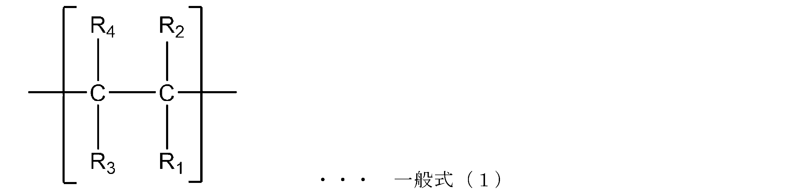
(ここで、式(1)中、R1及びR2は、それぞれ独立に、非極性基を表し、R3及びR4は、それぞれ独立に、水素原子、非極性基を表す。)
本構成体に用いる支持体(a)としては、特に制限されないが、例えば、ポリエステルフィルム、ポリアミドフィルム、ポリアクリロニトリルフィルム、ポリ塩化ビニルフィルム等が挙げられる。
本構成体は、支持体(a)上に感光性樹脂組成物層(b)を有する。感光性樹脂組成物層(b)は、支持体(a)上に直接積層されていてもよいし、上記接着剤層等を介して間接的に積層されていてもよい。
熱可塑性エラストマー(b-1)としては、特に制限されないが、例えば、モノビニル置換芳香族炭化水素に由来する構成単位と共役ジエンに由来する構成単位とを有する共重合体が挙げられる。なお、熱可塑性エラストマー(b-1)は、その他の単量体に由来する構成単位をさらに有していてもよい。このような熱可塑性エラストマーを用いることにより、本構成体を用いて製造したフレキソ印刷版の耐刷性がより向上する傾向にある。
(A-B)n、A-(B-A)n、A-(B-A)n-B、B-(A-B)n
一般式群(II):
[(A-B)k]m-X、[(A-B)k-A]m-X、[(B-A)k]m-X、[(B-A)k-B]m-X
感光性樹脂組成物層(b)は、上述したように、エチレン性不飽和化合物(b-2)を含有することが好ましい。エチレン性不飽和化合物(b-2)とは、ラジカル重合可能な不飽和二重結合を有する化合物である。
感光性樹脂組成物層(b)は、光重合開始剤(b-3)を含有することが好ましい。光重合開始剤(b-3)とは、光のエネルギーを吸収し、ラジカルを発生する化合物であり、崩壊型光重合開始剤、水素引抜き型光重合開始剤、水素引抜き型光重合開始剤として機能する部位と崩壊型光重合開始剤として機能する部位を同一分子内に有する化合物等が挙げられる。
感光性樹脂組成物層(b)には、液状ジエンを含有することが好ましい。液状ジエンとは液状の炭素・炭素二重結合を有する化合物である。ここで、本明細書中、「液状ジエン」の「液状」とは、容易に流動変形し、かつ冷却により変形された形状に固化できるという性質を有する性状を意味する。液状ジエンは、外力を加えたときに、その外力に応じて瞬時に変形し、かつ外力を除いたときには、短時間に元の形状を回復する性質を有するエラストマー性を備える。
補助添加成分としては、特に制限されないが、例えば、極性基含有ポリマー、液状ジエン以外の可塑剤、安定剤以外の熱重合防止剤、酸化防止剤、紫外線吸収剤、染料・顔料等が挙げられる。
本構成体は、上述した感光性樹脂組成物層(b)の上に、赤外線アブレーション層(c)が積層されている。赤外線アブレーション層(c)は、所定の樹脂を含有し、赤外線レーザーで切除可能であり、かつ、赤外線以外の光線遮蔽層としての機能を有している。
本実施形態の赤外線アブレーション層(c)に含まれる樹脂は、下記一般式(1)で表されるように、2つの非極性基が結合する4級炭素原子を含む構成単位(c1)を有し、必要に応じて、他の構成単位を有していてもよい。

(ここで、式(1)中、R1及びR2は、それぞれ独立に、非極性基を表し、R3及びR4は、それぞれ独立に、水素原子、非極性基を表す。)
赤外線アブレーション層(c)は、アブレーション加工を行うため赤外線吸収物質を含有してもよい。赤外線吸収物質には通常750~2000nmの範囲で強い吸収をもつ単体あるいは化合物が使用される。
赤外線アブレーション層(c)は、マスクとしての役割を担うため、紫外線などの非赤外線に対する遮蔽物質を含有してもよい。非赤外線に対する遮蔽物質としては紫外光を反射または吸収する物質を用いることができる。紫外線吸収剤やカーボンブラック、グラファイトなどが挙げられる。
赤外線アブレーション層(c)が溶剤系現像液に対して優れた現像性を発現するには、赤外線アブレーション層(c)中の樹脂を低極性にすることが重要である。しかしながら、樹脂が低極性であると水系現像液に対しては現像性が低下してしまう。一方で、赤外線アブレーション層(c)が水系現像液に対して優れた現像性を発現するには、赤外線アブレーション層(c)中の樹脂を高極性にすることが重要であるが、樹脂が高極性であると溶剤系現像液に対して現像性が低下してしまう。
赤外線アブレーション層(c)はカーボンブラックの分散性を補助する目的で分散剤を含有することが好ましい。ここで、分散剤としては、赤外線吸収剤の表面官能基と相互作用しうる吸着部と、バインダーポリマーと相溶し得る樹脂相溶部を有する化合物が好ましい。このような分散剤を用いることにより、カーボンブラックの分散性がより向上し、水系現像液への現像性がより向上する傾向にある。
δ=(ΔE/V)1/2 [(cal/cm3)1/2]・・・(1)
ここで、Vは溶媒のモル分子容、ΔEは凝集エネルギー(蒸発エネルギー)である。
δ=(Vml 1/2・δml+Vmh 1/2・δmh)/(Vml 1/2+Vmh 1/2)・・・(2)
ここで、Vmlは、SP値が低い貧溶媒の体積、VmhはSP値が高い貧溶媒の体積、δmlはSP値が低い貧溶媒のSP値、δmhはSP値が高い貧溶媒のSP値である。
本構成体の赤外線アブレーション層(c)の膜厚は、本構成体に対して露光処理を行う工程の際の紫外線に対する遮蔽性を確保する観点からは厚い方がよく、アブレーション性を高くする観点からは薄い方がよい。
本構成体は、感光性樹脂組成物層(b)と、赤外線アブレーション層(c)との間に、1層以上の中間層(d)を、さらに有していてもよい。中間層(d)は、特に制限されないが、例えば、酸素阻害層、接着層、及び/又は保護層とすることができる。以下、各層について説明する。
本実施形態のフレキソ印刷版の製造方法は、本構成体を用いて、まず、支持体(a)側から紫外線を照射する第一の工程と、赤外線アブレーション層(c)に赤外線を照射してパターンを描画加工する第二の工程と、パターンが描画加工された赤外線アブレーション層(c)をマスクとして、感光性樹脂組成物層(b)に紫外線を照射してパターン露光する第三の工程と、赤外線アブレーション層(c)と感光性樹脂組成物層(b)の未露光部を除去する第四の工程とを有する。
第一の工程において、支持体(a)側から感光性樹脂組成物層(b)へ紫外線照射する方法は、特に制限されず、公知の照射ユニットを使用して行うことができる。この際に照射する紫外線の波長は、好ましくは150~500nmであり、より好ましくは300~400nmである。
第二の工程において、赤外線アブレーション層(c)に赤外線を照射してパターンを描画加工する方法は、特に制限されず、公知の照射ユニットを使用して行うことができる。なお、赤外線アブレーション層(c)への赤外線の照射は、赤外線アブレーション層(c)側から行うことができる。
第三の工程は、パターンが描画加工された赤外線アブレーション層(c)をマスクとして、感光性樹脂組成物層(b)に紫外線を照射してパターン露光する。この際、マスクを通過した光が感光性樹脂組成物層(b)の硬化反応を促進し、赤外線アブレーション層(c)に形成されたパターンが、凹凸が反転して、感光性樹脂組成物層(b)に転写される。紫外線の照射は、本構成体の全面に照射してもよい。
第四の工程は、赤外線アブレーション層(b)と感光性樹脂組成物層(c)の未露光部を除去する工程である。第四の工程(現像工程における、除去方法は特に制限されず、従来公知の方法を適用できる。
本実施形態のフレキソ印刷方法は、上記フレキソ印刷版用感光性樹脂構成体を用い、支持体(a)側から紫外線を照射する第一の工程と、赤外線アブレーション層(c)に赤外線を照射してパターンを描画加工する第二の工程と、パターンが描画加工された赤外線アブレーション層(c)をマスクとして、感光性樹脂組成物層(b)に紫外線照射してパターン露光する第三の工程と、赤外線アブレーション層(c)と感光性樹脂組成物層(b)の未露光部を除去してフレキソ印刷版を製造する第四の工程と、フレキソ印刷版を用いて印刷する第五の工程と、を、有する。
第五の工程は、第一の工程から第四の工程によって得られたフレキソ印刷版を用いて印刷する工程である。フレキソ印刷版を用いた印刷方法は、フレキソ印刷版の凸部に対してインキを付着させ、そのインキを基材に転写させる方法であれば、特に制限されない。
以下の実施例及び比較例において、フレキソ印刷版用感光性樹脂構成体を製造した。
タフプレンA(旭化成製、スチレン-ブタジエン-スチレンブロック共重合体)60質量部と、B-2000(日本石油化学製、液状ポリブタジエン)30質量部、1,9-ノナンジオールジアクリレート7質量部、2,2-ジメトキシ-2-フェニルアセトフェノン2質量部、2,6-ジ-t-ブチル-p-クレゾール0.3質量部とを加圧ニーダーで混練し、感光性樹脂組成物を調製した。
<樹脂1の製造>
2Lのセパラブルフラスコの重合容器内を窒素置換した後、注射器を用いて、n-ヘキサン(モレキュラーシーブスで乾燥したもの)456.1mL及び塩化ブチル(モレキュラーシーブスで乾燥したもの)656.5mLを加え、重合容器を-70℃のドライアイス/メタノールバス中につけて冷却した後、イソブチレンモノマー161.1g(2871mmol)が入っている三方コック付耐圧ガラス製液化採取管にテフロン(登録商標)製の送液チューブを接続し、重合容器内にイソブチレンモノマーを窒素圧により送液した。p-ジクミルクロライド0.647g(2.8mmol)及びN,N-ジメチルアセトアミド1.22g(14mmol)を加えた。次にさらに四塩化チタン8.67mL(79.1mmol)を加えて重合を開始した。重合開始から1.5時間同じ温度で撹拌を行った後、重合溶液からサンプリング用として重合溶液約1mLを抜き取った。続いて、あらかじめ-70℃に冷却しておいたスチレンモノマー77.9g(748mmol)、n-ヘキサン23.9mLおよび塩化ブチル34.3mLの混合溶液を重合容器内に添加した。該混合溶液を添加してから45分後に、約40mLのメタノールを加えて反応を終了させた。
使用するモノマーの種類、配合比を下記表1のように変更した以外は樹脂1と同様にして樹脂2~9を得た。下記表1に、樹脂の構成材料及び物性を示す。
攪拌機を有する容器に、水2kg、第三リン酸カルシウム65g、炭酸カルシウム40g、ラウリル硫酸ナトリウム0.40gを投入し、混合液を得た。次いで、60Lの反応器に、水25kgを投入して80℃に昇温し、混合液及びメタクリル酸メチル21.5kg、ラウロイルパーオキサイド110g、2-エチルヘキシルチオグリコレート430gを投入した。その後、約75℃を保って懸濁重合を行い、発熱ピークを観測後、92℃に1℃/minの速度で昇温した。そして、60分間熟成し、重合反応を実質終了した。

<赤外線アブレーション層積層体1の製造例>
樹脂1:6.5質量部と、トルエン:54.0質量部と、シクロヘキサノン:36.0質量部と、を混合し、樹脂1を溶剤に溶解させた。その後、カーボンブラック(三菱ケミカル製、#1000)を3.5質量部をさらに投入し、ビーズミルで4時間混合しカーボンブラック分散液を得た。
使用する樹脂を、下記表2のように変更した以外は、赤外線アブレーション層積層体1と同様にして、赤外線アブレーション層積層体2~10を得た。
タフプレン315(旭化成製、スチレン-ブタジエンブロック共重合体)7.8質量部と、トルエン70.4質量部と、プロピレングリコール1-モノメチルエーテル2-アセタート(PMA)17.6質量部と、を混合し、タフプレン315を溶剤に溶解させた。その後、カーボンブラック(三菱ケミカル製、MCF-88)をさらに投入し、ビーズミルで4時間混合しカーボンブラック分散液を得た。
ポリアミド(ヘンケル社製、マクロメルト6900)7.8質量部と、トルエン44.0質量部と、2-プロパノール44.0質量部と、を混合し、ポリアミドを溶剤に溶解させた。その後、カーボンブラック(三菱ケミカル製、MCF-88)をさらに投入し、ビーズミルで4時間混合しカーボンブラック分散液を得た。
ゴーセノールKL-05(ケン化度78~82モル%のポリ酢酸ビニル、日本合成化学工業(株)製)10質量部と、ε-カプロラクタム10質量部、N-(2-アミノエチル)ピペラジンとアジピン酸のナイロン塩90質量部、及び水100質量部を、ステンレス製オートクレーブに入れ、内部の空気を窒素ガスで置換した後に180℃で1時間加熱し、水溶性ポリアミドを調製した。次いで水分を除去して得られた水溶性ポリアミド10質量部を、水40質量部、メタノール20質量部、n-プロパノール20質量部、及びn-ブタノール10質量部に溶解させ、溶液を得た。
攪拌装置付き加熱密閉容器にトルエン41部を仕込み、攪拌しながら変性ポリオレフィンハードレン13-LP(東洋紡製)を3.0部添加し、40℃の条件下で攪拌溶解を行った(第一段階)。常温まで放冷後、赤外線吸収物質としてカーボンブラックである三菱ケミカル製、MCF-88を6部添加し、90分プレミキシングを行った後に、サンドミルを用いカーボンブラックの分散を行った(第二段階)。その後再度40℃まで加熱を行い、トルエンを38.8部、メチルエチルケトンを3部およびハードレン13-LPを8.2部添加し攪拌溶解を行い(第三段階)、カーボンブラック:樹脂=35:65質量比の赤外線アブレーション層の塗工液を調製した。
セプトン2005(クラレ社製、スチレン:20wt%、プロピレン構造(R1がメチル基、R2~R4が水素原子):40wt%)7.8質量部と、トルエン70.4質量部と、プロピレングリコール1-モノメチルエーテル2-アセタート(PMA)17.6質量部と、を混合し、セプトン2005を溶剤に溶解させた。その後、カーボンブラック(三菱ケミカル製、MCF-88)をさらに投入し、ビーズミルで4時間混合しカーボンブラック分散液を得た。

<実施例1>
支持体と感光性樹脂組成物層の積層体から離型フィルムをはがし、赤外線アブレーション層積層体1を、赤外線アブレーション層が感光性樹脂組成物層に接するように、温度25℃、湿度40%の環境でラミネートし、120℃に設定したホットプレート上でカバーフィルム面をホットプレートの加熱部に接触するように配置して、1分間熱を加えて実施例1のフレキソ印刷版用感光性樹脂構成体1を得た。
<レーザー感度の評価>
フレキソ印刷版用感光性樹脂構成体を、Esko CDI SPARK2530に設置し、解像度8000dpi、レーザー強度3.0Jにおいて、2×1ピクセルの計2ピクセルを形成する画像パターンを持つテスト画像でレーザー描画を行った。
(評価基準)
A:穴は貫通しており感光性樹脂組成物との界面/赤外線アブレーション層表面の長さが0.50以上
B:穴は貫通しており感光性樹脂組成物との界面/赤外線アブレーション層表面の長さが0.40以上0.50未満
C:穴は貫通しており感光性樹脂組成物との界面/赤外線アブレーション層表面の長さが0.30以上0.40未満
D:穴は貫通しており感光性樹脂組成物との界面/赤外線アブレーション層表面の長さが0.30未満
E:穴は貫通していない
フレキソ印刷版用感光性樹脂構成体を、中央付近を起点に、支持体が内側になるように180°(支持体が接触する程度)折り曲げ、その後、赤外線アブレーション層表面にしわが発生するか試験を行い、下記のように評価した。
(評価基準)
A:しわが発生しない。
B:しわが発生するが、構成体の端部のみにごくわずかに発生する。
C:しわが発生し、構成体の端部に複数発生する。
D:しわが発生し、構成体の端部だけでなく中央付近にしわがみられる。
E:構成体の全面にしわが発生する。
赤外線アブレーション層積層体1を、赤外線アブレーション層が感光性樹脂組成物層に接するよう温度180℃でラミネートしサンプルを得た。このサンプルにおいて、赤外線アブレーション層のカバーフィルムを除去した後、ライトテーブル上に置き、顕微鏡検査を行った。赤外線アブレーション層において、長径20μm以上のサイズのピンホールの個数を数え、平均値を算出し、(個/m2)の値を算出し、下記のように評価した。
(評価基準)
A:ピンホールの数が、平均2(個/m2)より少ない。
B:ピンホールの数が、平均2(個/m2)以上で5(個/m2)より少ない。
C:ピンホールの数が、平均5(個/m2)以上で10(個/m2)より少ない。
D:ピンホールの数が、平均10(個/m2)以上で20(個/m2)より少ない。
E:ピンホールの数が、平均20(個/m2)以上である。
それぞれ赤外線アブレーション層積層体の種類を赤外線アブレーション層積層体2~12に変更した以外は、実施例1と同様にして、実施例2~15のフレキソ印刷版用感光性樹脂構成体2~15を作製し、評価を行った。評価結果を下記表3に示す。
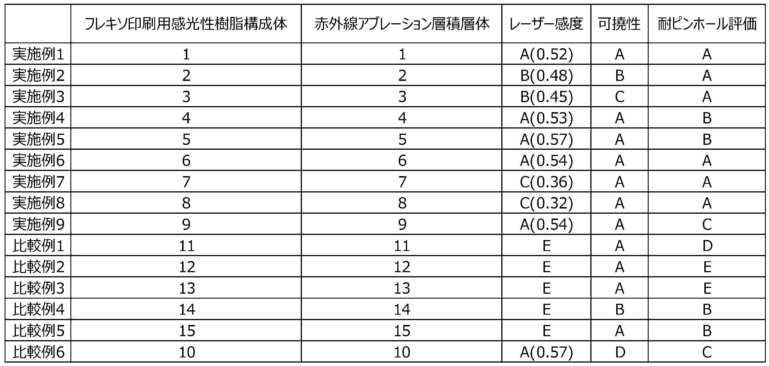
撹拌装置と温度調節用ジャケットを取り付けた耐圧反応容器に、水125質量部と、反応性乳化剤として(α-スルフォ(1-ノニルフェノキシ)メチル-2-(2-プロペニルオキシ)エトキシ-ポリ(オキシ-1,2-エタンジイル)のアンモニウム塩「アデカリアソープ」(旭電化工業製)2質量部を初期仕込みし、内温を80℃に昇温し、スチレン10質量部、ブタジエン60質量部、ブチルアクリレート23質量部、メタアクリル酸5質量部、及び、アクリル酸2質量部からなる単量体混合物とt-ドデシルメルカプタン2質量部との油性混合液と、水28質量部、ペルオキソ二硫酸ナトリウム1.2質量部、水酸化ナトリウム0.2質量部、及び、(α-スルフォ(1-ノニルフェノキシ)メチル-2-(2-プロペニルオキシ)エトキシ-ポリ(オキシ-1,2-エタンジイル)のアンモニウム塩2質量部からなる水溶液を、油性混合液を5時間、水溶液を6時間かけて一定の流速で添加した。ついで、80℃の温度をそのまま1時間保って、重合反応を完了し、共重合体ラテックスを得た後、冷却した。
支持体(ベースフィルム)にコートする接着剤層用の溶液として、スチレンと1,3-ブタジエンのブロック共重合体であるタフプレン912(旭化成株式会社製、商品名)を55質量部、パラフィンオイル(平均炭素数33、平均分子量470、15℃における密度0.868)を38質量部、1,9-ノナンジオールジアクリレートを2.5質量部、2,2-ジメトキシ-フェニルアセトフェノンを1.5質量部、エポキシエステル3000M(共栄社化学株式会社製、商品名)を3質量部、及びバリファストイエロー3150(オリエント化学工業製、商品名)を1.5質量部の割合で、トルエンに溶解させ固形分25%の溶液を得た。
上記(101-1)で調製した親水性共重合体32質量部と、スチレン-ブタジエン-スチレン共重合体[D-KX405:クレイトン製]28質量部を、加圧ニーダーを用いて140℃で混合後、液状ポリブタジエン[LBR-352:クラレ製]32質量部、1,9-ノナンジオールジアクリレート8質量部、1,6-ヘキサンジオールジメタクリレート5質量部、2,2-ジメトキシフェニルアセトフェノン2質量部、2,6-ジ-t-ブチル-p-クレゾール1質量部、カルビノール変性シリコーンオイル[KF-6000:信越化学製]1質量部の液状混合物を15分掛けて少しずつ加えて、加え終えてさらに20分混練し、感光性樹脂組成物を得た。
<樹脂101の製造>
2Lのセパラブルフラスコの重合容器内を窒素置換した後、注射器を用いて、n-ヘキサン(モレキュラーシーブスで乾燥したもの)456.1mL及び塩化ブチル(モレキュラーシーブスで乾燥したもの)656.5mLを加え、重合容器を-70℃のドライアイス/メタノールバス中につけて冷却した後、イソブチレンモノマー161.1g(2871mmol)が入っている三方コック付耐圧ガラス製液化採取管にテフロン(登録商標)製の送液チューブを接続し、重合容器内にイソブチレンモノマーを窒素圧により送液した。p-ジクミルクロライド0.647g(2.8mmol)及びN,N-ジメチルアセトアミド1.22g(14mmol)を加えた。次にさらに四塩化チタン8.67mL(79.1mmol)を加えて重合を開始した。重合開始から1.5時間同じ温度で撹拌を行った後、重合溶液からサンプリング用として重合溶液約1mLを抜き取った。続いて、あらかじめ-70℃に冷却しておいたスチレンモノマー77.9g(748mmol)、n-ヘキサン23.9mLおよび塩化ブチル34.3mLの混合溶液を重合容器内に添加した。該混合溶液を添加してから45分後に、約40mLのメタノールを加えて反応を終了させた。
使用するモノマーの種類、配合比を下記表4のように変更した以外は樹脂101と同様にして樹脂102~105を得た。下記表4に、樹脂の構成材料及び物性を示す。

<赤外線アブレーション層積層体101の製造例>
樹脂1:6.5質量部と、トルエン:54.0質量部と、シクロヘキサノン:36.0質量部と、を混合し、樹脂1を溶剤に溶解させた。その後、カーボンブラック(三菱ケミカル製、#1000、pH=3.5)3.5質量部と、Solsperse39000(日本ルーブリゾール株式会社製、SP値:11.5)と1.2質量部をさらに投入し、その後、ビーズミルで4時間混合しカーボンブラック分散液を得た。
使用する樹脂を、下記表5のように変更した以外は、赤外線アブレーション層積層体101と同様にして赤外線アブレーション層積層体102~107、109~119、129を得た。
攪拌装置付き加熱密閉容器にトルエン41部を仕込み、攪拌しながら塩素化プロピレンスーパークロンHP-205(日本製紙製、塩素化度68%)を3.0部添加し、40℃の条件下で攪拌溶解を行った(第一段階)。常温まで放冷後、赤外線吸収物質としてカーボンブラックである三菱ケミカル製、#1000を6部、分散剤S39000を1.1部添加し、90分プレミキシングを行った後に、サンドミルを用いカーボンブラックの分散を行った(第二段階)。その後再度40℃まで加熱を行い、トルエンを38.8部、メチルエチルケトンを3部およびスーパークロンHP-205を8.2部添加し攪拌溶解を行い(第三段階)、カーボンブラック:樹脂=35:65質量比の赤外線アブレーション層の塗工液を調製した。
使用するカーボンブラックを、Printex35(デクサ製、pH=9.5)に変更した以外は、赤外線アブレーション層積層体8と同様にして赤外線アブレーション層積層体120を得た。
スチレン-ブタジエン-スチレン共重合体エラストマーの水素添加物(旭化成製、タフテックH1051)7.8質量部と、トルエン70.4質量部と、プロピレングリコール1-モノメチルエーテル2-アセタート(PMA)17.6質量部と、を混合し、樹脂を溶解させた。その後、カーボンブラック(三菱ケミカル製、#30、pH=8.0)を4.2質量部、Solsperse39000(日本ルーブリゾール株式会社製)を0.6質量部をさらに投入し、ビーズミルで4時間混合しカーボンブラック分散液を得た。
使用するカーボンブラックを、#1000(三菱ケミカル製、pH=3.5)に変更した以外は、赤外線アブレーション層積層体121と同様にして赤外線アブレーション層積層体122を得た。
ポリアミド(ヘンケル社製、マクロメルト6900)7.8質量部と、トルエン44.0質量部と、2-プロパノール44.0質量部と、を混合し、樹脂を溶解させた。その後、カーボンブラック(三菱ケミカル製、#30、pH=8.0)4.2質量部、Solsperse39000(日本ルーブリゾール株式会社製)0.6質量部をさらに投入し、ビーズミルで4時間混合しカーボンブラック分散液を得た。
使用するカーボンブラックを、#1000に変更した以外は、赤外線アブレーション層積層体123と同様にして赤外線アブレーション層積層体124を得た。
ゴーセノールKL-05(ケン化度78~82モル%のポリ酢酸ビニル、日本合成化学工業(株)製)10質量部と、ε-カプロラクタム10質量部、N-(2-アミノエチル)ピペラジンとアジピン酸のナイロン塩90質量部、及び水100質量部を、ステンレス製オートクレーブに入れ、内部の空気を窒素ガスで置換した後に180℃で1時間加熱し、水溶性ポリアミドを調製した。次いで水分を除去して得られた水溶性ポリアミド10質量部を、水40質量部、メタノール20質量部、n-プロパノール20質量部、及びn-ブタノール10質量部に溶解させ、溶液を得た。溶液に、カーボンブラック(三菱ケミカル製、MA-100、pH=3.5)を混合し、3本ロールミルを用いて混練分散させ、カーボンブラック分散液を得た。
使用するカーボンブラックを、#30に変更した以外は、赤外線アブレーション層積層体125と同様にして赤外線アブレーション層積層体126を得た。
酸変性ポリマー(東亜合成製、UC-3510)0.5質量部と、スチレン-ブタジエン-スチレンエラストマーの水素添加物(旭化成製、タフテックH1051)1.3質量部と、トルエン44質量部と、を混合し、樹脂を溶解させた。その後、カーボンブラック(三菱ケミカル製、#30、pH=8.0)4.2質量部、Solsperse39000(日本ルーブリゾール株式会社製)0.6質量部をさらに投入し、ビーズミルで4時間混合しカーボンブラック分散液を得た。
下記表5に、構成材料を示す。
使用するカーボンブラックを、#1000に変更した以外は、赤外線アブレーション層積層体127と同様にして赤外線アブレーション層積層体128を得た。

<実施例101>
支持体と感光性樹脂組成物層の積層体から離型フィルムをはがし、赤外線アブレーション層積層体101を、赤外線アブレーション層が感光性樹脂組成物層に接するように、温度25℃、湿度40%の環境でラミネートし、120℃に設定したホットプレート上でカバーフィルム面をホットプレートの加熱部に接触するように配置して、1分間熱を加えて実施例101のフレキソ印刷版用感光性樹脂構成体101を得た。
<溶剤系現像液に対する現像性評価>
フレキソ印刷版用感光性樹脂構成体を、3-メトキシブチルアセテートを現像液として、「AFP-1500」現像機(旭化成社製、商品名)の回転するドラムに両面テープを貼り付けて固定を行い、液温25℃で現像を行い、60℃で2時間乾燥させた。0.8mm現像するのに要する時間を測定した。
(評価基準)
A:赤外線アブレーション層があることで現像時間が30秒未満悪化する。
B:赤外線アブレーション層があることで現像時間が30秒以上1分未満悪化する。
C:赤外線アブレーション層があることで現像時間が1分以上2分未満悪化する。
D:赤外線アブレーション層があることで現像時間が2分以上3分未満悪化する。
E:赤外線アブレーション層があることで3分以上時間を追加しても十分に洗浄できない。
日本電子精機製現像機(JOW-A3-P)にニッサン石鹸1%水溶液を充填し、(2)で得られた印刷原版の赤外線アブレーション層のカバーフィルムを剥がして液温40℃で現像した。60℃で10分乾燥させた。0.8mm現像するのに要する時間を測定した。
(評価基準)
A:赤外線アブレーション層があっても現像時間の悪化は1分未満であった。
B:赤外線アブレーション層があることで現像時間が1分以上2分未満悪化する。
C:赤外線アブレーション層があることで現像時間が2分以上3分未満悪化する。
D:赤外線アブレーション層があることで現像時間が3分以上5分未満悪化する。
E:赤外線アブレーション層があることで5分以上時間を追加しても十分に洗浄できない。
フレキソ印刷版用感光性樹脂構成体を適切な大きさに切断した後、紫外線硬化樹脂を用いて樹脂包埋した。樹脂包埋後、クライオミクロトーム法により作製した断面をSEM観察試料とした。
〇断面加工条件
使用装置:ウルトラミクロトーム UC6(LEICA製)
設定温度:-80℃
設定切削厚み:100nm
〇SEM観察条件
測定装置:走査型電子顕微鏡 S4800(日立製)
加速電圧:1.0kV
観察倍率:5.0k
赤外線アブレーション層を観察し、得られた断面SEM観察像から下記のように評価した。
(評価基準)
A:カーボンブラックが均一に分散しており凝集塊がみられない。
B:カーボンブラックが均一に分散しており、凝集塊が一視野に2個未満である。
C:カーボンブラックが均一に分散しており、凝集塊が一視野に5個未満である。
E:カーボンブラックが偏在しており、凝集塊が一視野に5個以上存在する、もしくはカーボンブラックが存在しない領域が広く存在する。
それぞれ赤外線アブレーション層積層体の種類を赤外線アブレーション層積層体102~129に変更した以外は、実施例101と同様にして、実施例102~119及び比較例101~110のフレキソ印刷版用感光性樹脂構成体102~129を作製し、評価を行った。評価結果を、下記表6に示す。

Claims (14)
- 少なくとも、支持体(a)と、
該支持体(a)上に積層される感光性樹脂組成物層(b)と、
該感光性樹脂組成物層(b)上に積層される赤外線アブレーション層(c)と、を備え、
前記赤外線アブレーション層(c)が、下記一般式(1)で表される構成単位c1を有する樹脂を含有する、
フレキソ印刷版用感光性樹脂構成体。

- 前記構成単位(c1)の含有量が、前記樹脂の総量に対して、40質量%以上100質量%以下である、
請求項1に記載のフレキソ印刷版用感光性樹脂構成体。 - 前記一般式(1)のR3及びR4が、それぞれ独立に、水素原子、アルキル基、アリール基、シクロアルキル基、フェニル基、アルケニル基、アラルキル基、シクロアルケニル基、アルキニル基、シリル基、シロキサニル基である、
請求項1又は2に記載のフレキソ印刷版用感光性樹脂構成体。 - 前記一般式(1)のR3及びR4が、水素原子である、
請求項1~3のいずれか一項に記載のフレキソ印刷版用感光性樹脂構成体。 - 前記一般式(1)のR1及びR2が、それぞれ独立に、アルキル基、アリール基、シクロアルキル基、フェニル基、アルケニル基、アラルキル基、シクロアルケニル基、アルキニル基、シリル基、シロキサニル基である、
請求項1~4のいずれか一項に記載のフレキソ印刷版用感光性樹脂構成体。 - 前記一般式(1)のR1及びR2が、それぞれ独立に、アルキル基又はフェニル基である、
請求項1~5のいずれか一項に記載のフレキソ印刷版用感光性樹脂構成体。 - 前記一般式(1)のR1及びR2が、アルキル基である、
請求項1~6のいずれか一項に記載のフレキソ印刷版用感光性樹脂構成体。 - 前記樹脂は、前記構成単位(c1)とは異なり、側鎖に芳香族基を含む構成単位(c2)をさらに有する、
請求項1~7のいずれか一項に記載のフレキソ印刷版用感光性樹脂構成体。 - 前記構成単位(c2)は、モノビニル置換芳香族炭化水素に由来する構成単位を含む、
請求項1~8のいずれか一項に記載のフレキソ印刷版用感光性樹脂構成体。 - 前記赤外線アブレーション層(c)が、カーボンブラックを含有し、
前記カーボンブラックのpHが、2.0以上5.0以下である、
請求項1~9のいずれか一項に記載のフレキソ印刷版用感光性樹脂構成体。 - 前記赤外線アブレーション層(c)が分散剤を含有し、
前記分散剤の溶解度パラメータ(SP値)が、9.5以上12.5以下である、
請求項1~10のいずれか一項に記載のフレキソ印刷版用感光性樹脂構成体。 - 前記赤外線アブレーション層(c)における前記樹脂と前記カーボンブラックの配合比(樹脂/カーボンブラック)が、80/20~50/50の範囲にある、
請求項1~11のいずれか一項に記載のフレキソ印刷版用感光性樹脂構成体。 - 請求項1~12のいずれか一項に記載のフレキソ印刷版用感光性樹脂構成体を用い、
前記支持体(a)側から紫外線を照射する第一の工程と、
前記赤外線アブレーション層(c)に赤外線を照射してパターンを描画加工する第二の工程と、
前記パターンが描画加工された前記赤外線アブレーション層(c)をマスクとして、前記感光性樹脂組成物層(b)に紫外線照射してパターン露光する第三の工程と、
前記赤外線アブレーション層(c)と前記感光性樹脂組成物層(b)の未露光部を除去する第四の工程と、を、有する、
フレキソ印刷版の製造方法。 - 請求項1~12のいずれか一項に記載のフレキソ印刷版用感光性樹脂構成体を用い、
前記支持体(a)側から紫外線を照射する第一の工程と、
前記赤外線アブレーション層(c)に赤外線を照射してパターンを描画加工する第二の工程と、
前記パターンが描画加工された前記赤外線アブレーション層(c)をマスクとして、前記感光性樹脂組成物層(b)に紫外線照射してパターン露光する第三の工程と、
前記赤外線アブレーション層(c)と前記感光性樹脂組成物層(b)の未露光部を除去してフレキソ印刷版を製造する第四の工程と、
前記フレキソ印刷版を用いて印刷する第五の工程と、を、有する、
フレキソ印刷方法。
Priority Applications (4)
| Application Number | Priority Date | Filing Date | Title |
|---|---|---|---|
| CN202180090270.4A CN116745129A (zh) | 2021-01-20 | 2021-12-14 | 柔性印刷版用感光性树脂结构体和柔性印刷版的制造方法 |
| US18/037,437 US12019374B2 (en) | 2021-01-20 | 2021-12-14 | Photosensitive resin structure for flexographic printing plate and method for producing flexographic printing plate |
| EP21921274.3A EP4282656A4 (en) | 2021-01-20 | 2021-12-14 | PHOTOSENSITIVE RESIN STRUCTURE FOR FLEXOGRAPHIC PRINTING PLATE AND METHOD FOR PRODUCING A FLEXOGRAPHIC PRINTING PLATE |
| JP2022577032A JP7474875B2 (ja) | 2021-01-20 | 2021-12-14 | フレキソ印刷版用感光性樹脂構成体、及びフレキソ印刷版の製造方法 |
Applications Claiming Priority (4)
| Application Number | Priority Date | Filing Date | Title |
|---|---|---|---|
| JP2021007168 | 2021-01-20 | ||
| JP2021-007168 | 2021-01-20 | ||
| JP2021-007103 | 2021-01-20 | ||
| JP2021007103 | 2021-01-20 |
Publications (1)
| Publication Number | Publication Date |
|---|---|
| WO2022158172A1 true WO2022158172A1 (ja) | 2022-07-28 |
Family
ID=82548341
Family Applications (1)
| Application Number | Title | Priority Date | Filing Date |
|---|---|---|---|
| PCT/JP2021/046025 Ceased WO2022158172A1 (ja) | 2021-01-20 | 2021-12-14 | フレキソ印刷版用感光性樹脂構成体、及びフレキソ印刷版の製造方法 |
Country Status (4)
| Country | Link |
|---|---|
| US (1) | US12019374B2 (ja) |
| EP (1) | EP4282656A4 (ja) |
| JP (1) | JP7474875B2 (ja) |
| WO (1) | WO2022158172A1 (ja) |
Cited By (2)
| Publication number | Priority date | Publication date | Assignee | Title |
|---|---|---|---|---|
| WO2025143201A1 (ja) * | 2023-12-27 | 2025-07-03 | 旭化成株式会社 | 印刷版の製造方法 |
| EP4553578A4 (en) * | 2022-07-05 | 2025-12-24 | Asahi Chemical Ind | FILM FOR THE MANUFACTURE OF A FLEXOGRAPHIC IMAGE, LAMINATED AND METHOD FOR MANUFACTURED A FLEXOGRAPHIC IMAGE |
Citations (9)
| Publication number | Priority date | Publication date | Assignee | Title |
|---|---|---|---|---|
| JP2916408B2 (ja) | 1995-05-01 | 1999-07-05 | イー・アイ・デュポン・ドウ・ヌムール・アンド・カンパニー | 赤外アブレーション性層をもつフレキソグラフ用エレメントおよびフレキソグラフ印刷板の作成方法 |
| JP2002357907A (ja) * | 2001-03-06 | 2002-12-13 | E I Du Pont De Nemours & Co | フレキソ印刷版の製造方法および該方法に使用する感光性要素 |
| WO2004104701A1 (ja) | 2003-05-23 | 2004-12-02 | Asahi Kasei Chemicals Corporation | フレキソ印刷用感光性構成体 |
| JP4080068B2 (ja) | 1997-09-16 | 2008-04-23 | 旭化成ケミカルズ株式会社 | フレキソ印刷版用感光性構成体 |
| JP2010237583A (ja) * | 2009-03-31 | 2010-10-21 | Toray Ind Inc | 水系現像感光性樹脂印刷原版 |
| JP2014119594A (ja) * | 2012-12-17 | 2014-06-30 | Jsr Corp | 赤外線アブレーション層を有するフレキソ印刷版用感光性樹脂積層体 |
| JP2015011330A (ja) | 2013-07-02 | 2015-01-19 | 日本電子精機株式会社 | 改良された赤外線アブレーション層を有するフレキソ印刷版用感光性樹脂積層体 |
| JP2016188900A (ja) | 2015-03-30 | 2016-11-04 | 東レ株式会社 | 感光性樹脂積層体 |
| WO2020122001A1 (ja) * | 2018-12-10 | 2020-06-18 | 旭化成株式会社 | フレキソ印刷原版及びフレキソ印刷版の製造方法 |
Family Cites Families (13)
| Publication number | Priority date | Publication date | Assignee | Title |
|---|---|---|---|---|
| US5506086A (en) * | 1995-05-01 | 1996-04-09 | E. I. Du Pont De Nemours And Company | Process for making a flexographic printing plate |
| US20040241573A1 (en) | 2003-06-02 | 2004-12-02 | Ray Kevin Barry | Thermally sensitive, white light safe mask for use in flexography |
| US7226709B1 (en) | 2006-06-20 | 2007-06-05 | Eastman Kodak Company | Digital mask-forming film and method of use |
| JP4980038B2 (ja) * | 2006-09-20 | 2012-07-18 | 東京応化工業株式会社 | 保護膜形成用材料及びホトレジストパターンの形成方法 |
| JP2009063873A (ja) | 2007-09-07 | 2009-03-26 | Toray Ind Inc | 感光性印刷版原版 |
| JP2009119810A (ja) | 2007-11-19 | 2009-06-04 | Asahi Kasei Chemicals Corp | レーザー彫刻用感光性樹脂組成物 |
| TWI363785B (en) * | 2007-11-30 | 2012-05-11 | Ind Tech Res Inst | Ink composition and fabrication method of color conversion film |
| US20110236705A1 (en) * | 2010-03-29 | 2011-09-29 | Ophira Melamed | Flexographic printing precursors and methods of making |
| JP5710961B2 (ja) | 2010-12-24 | 2015-04-30 | 住友理工株式会社 | フレキソ印刷版原版 |
| JP6232279B2 (ja) | 2013-12-24 | 2017-11-15 | 住友理工株式会社 | 赤外線アブレーション層用積層体、フレキソ印刷版原版、赤外線アブレーション層用積層体の製造方法 |
| JP6598338B2 (ja) | 2016-09-23 | 2019-10-30 | 旭化成株式会社 | アブレーション層、感光性樹脂構成体、及び当該感光性樹脂構成体を用いた凸版印刷版の製造方法 |
| JP7229332B2 (ja) | 2019-02-27 | 2023-02-27 | 旭化成株式会社 | フレキソ印刷原版及びフレキソ印刷版の製造方法 |
| WO2020209145A1 (ja) | 2019-04-12 | 2020-10-15 | 富士フイルム株式会社 | 水現像性フレキソ印刷版原版、フレキソ印刷版および感光性樹脂組成物 |
-
2021
- 2021-12-14 EP EP21921274.3A patent/EP4282656A4/en active Pending
- 2021-12-14 WO PCT/JP2021/046025 patent/WO2022158172A1/ja not_active Ceased
- 2021-12-14 JP JP2022577032A patent/JP7474875B2/ja active Active
- 2021-12-14 US US18/037,437 patent/US12019374B2/en active Active
Patent Citations (9)
| Publication number | Priority date | Publication date | Assignee | Title |
|---|---|---|---|---|
| JP2916408B2 (ja) | 1995-05-01 | 1999-07-05 | イー・アイ・デュポン・ドウ・ヌムール・アンド・カンパニー | 赤外アブレーション性層をもつフレキソグラフ用エレメントおよびフレキソグラフ印刷板の作成方法 |
| JP4080068B2 (ja) | 1997-09-16 | 2008-04-23 | 旭化成ケミカルズ株式会社 | フレキソ印刷版用感光性構成体 |
| JP2002357907A (ja) * | 2001-03-06 | 2002-12-13 | E I Du Pont De Nemours & Co | フレキソ印刷版の製造方法および該方法に使用する感光性要素 |
| WO2004104701A1 (ja) | 2003-05-23 | 2004-12-02 | Asahi Kasei Chemicals Corporation | フレキソ印刷用感光性構成体 |
| JP2010237583A (ja) * | 2009-03-31 | 2010-10-21 | Toray Ind Inc | 水系現像感光性樹脂印刷原版 |
| JP2014119594A (ja) * | 2012-12-17 | 2014-06-30 | Jsr Corp | 赤外線アブレーション層を有するフレキソ印刷版用感光性樹脂積層体 |
| JP2015011330A (ja) | 2013-07-02 | 2015-01-19 | 日本電子精機株式会社 | 改良された赤外線アブレーション層を有するフレキソ印刷版用感光性樹脂積層体 |
| JP2016188900A (ja) | 2015-03-30 | 2016-11-04 | 東レ株式会社 | 感光性樹脂積層体 |
| WO2020122001A1 (ja) * | 2018-12-10 | 2020-06-18 | 旭化成株式会社 | フレキソ印刷原版及びフレキソ印刷版の製造方法 |
Non-Patent Citations (2)
| Title |
|---|
| POLYMER ENGINEERING AND SCIENCE, vol. 14, 1974, pages 147 - 154 |
| See also references of EP4282656A4 |
Cited By (2)
| Publication number | Priority date | Publication date | Assignee | Title |
|---|---|---|---|---|
| EP4553578A4 (en) * | 2022-07-05 | 2025-12-24 | Asahi Chemical Ind | FILM FOR THE MANUFACTURE OF A FLEXOGRAPHIC IMAGE, LAMINATED AND METHOD FOR MANUFACTURED A FLEXOGRAPHIC IMAGE |
| WO2025143201A1 (ja) * | 2023-12-27 | 2025-07-03 | 旭化成株式会社 | 印刷版の製造方法 |
Also Published As
| Publication number | Publication date |
|---|---|
| US20240012328A1 (en) | 2024-01-11 |
| EP4282656A1 (en) | 2023-11-29 |
| EP4282656A4 (en) | 2024-07-17 |
| JPWO2022158172A1 (ja) | 2022-07-28 |
| JP7474875B2 (ja) | 2024-04-25 |
| US12019374B2 (en) | 2024-06-25 |
Similar Documents
| Publication | Publication Date | Title |
|---|---|---|
| US11796914B2 (en) | Photosensitive resin structure for printing plate, and method for producing same | |
| JP7028560B2 (ja) | フレキソ印刷版 | |
| JP7474875B2 (ja) | フレキソ印刷版用感光性樹脂構成体、及びフレキソ印刷版の製造方法 | |
| JP7489475B2 (ja) | フレキソ印刷版用感光性構成体、及びフレキソ印刷版の製造方法 | |
| KR100833743B1 (ko) | 플렉소 인쇄판용 감광성 수지 | |
| JP7836681B2 (ja) | フレキソ印刷版用感光性樹脂構成体、及びフレキソ印刷版の製造方法 | |
| JP2020173308A (ja) | 印刷版用感光性樹脂組成物、印刷版用感光性樹脂構成体、及び印刷版の製造方法 | |
| WO2024009674A1 (ja) | フレキソ印刷版製造用フィルム、積層体、及びフレキソ印刷版の製造方法 | |
| CN112020203A (zh) | 柔性印刷原版、及柔性印刷版的制造方法 | |
| CN116745129A (zh) | 柔性印刷版用感光性树脂结构体和柔性印刷版的制造方法 | |
| JP7724169B2 (ja) | フレキソ印刷版用感光性樹脂構成体、フレキソ印刷版の製造方法、及び印刷方法 | |
| JP7095956B2 (ja) | 印刷版用感光性樹脂版の製造方法 | |
| JP2024029911A (ja) | フレキソ印刷版用感光性樹脂構成体、及びフレキソ印刷版の製造方法 | |
| JP6397194B2 (ja) | 印刷版用感光性樹脂組成物、印刷版用感光性樹脂構成体、及び印刷版 | |
| JP7108376B2 (ja) | フレキソ印刷原版及びフレキソ印刷版 | |
| JP2018116109A (ja) | 印刷版用感光性樹脂版の製造方法 | |
| WO2024225145A1 (ja) | フレキソ印刷原版、及びフレキソ印刷版の製造方法 | |
| JP7720483B2 (ja) | フレキソ印刷原版、フレキソ印刷版の製造方法、フレキソ印刷版、及びフレキソ印刷方法 | |
| JP2003177514A (ja) | 感光性印刷用原版 | |
| JP2019109444A (ja) | フレキソ印刷用感光性樹脂版の製造方法 | |
| US20250313029A1 (en) | Photosensitive resin composition, flexographic printing raw plate, and manufacturing method of flexographic printing plate | |
| JP2018205542A (ja) | 印刷版用感光性樹脂版の製造方法 | |
| WO2025206369A1 (ja) | フレキソ印刷原版、フレキソ印刷版の製造方法、フレキソ印刷方法、及び支持体 | |
| CN117980832A (zh) | 柔性印刷版的制造方法和印刷方法 | |
| JP2018116110A (ja) | 印刷版用感光性樹脂版の製造方法 |
Legal Events
| Date | Code | Title | Description |
|---|---|---|---|
| 121 | Ep: the epo has been informed by wipo that ep was designated in this application |
Ref document number: 21921274 Country of ref document: EP Kind code of ref document: A1 |
|
| ENP | Entry into the national phase |
Ref document number: 2022577032 Country of ref document: JP Kind code of ref document: A |
|
| WWE | Wipo information: entry into national phase |
Ref document number: 18037437 Country of ref document: US |
|
| WWE | Wipo information: entry into national phase |
Ref document number: 202180090270.4 Country of ref document: CN |
|
| NENP | Non-entry into the national phase |
Ref country code: DE |
|
| ENP | Entry into the national phase |
Ref document number: 2021921274 Country of ref document: EP Effective date: 20230821 |