WO2022158204A1 - 冷却水落下防止システム - Google Patents
冷却水落下防止システム Download PDFInfo
- Publication number
- WO2022158204A1 WO2022158204A1 PCT/JP2021/046828 JP2021046828W WO2022158204A1 WO 2022158204 A1 WO2022158204 A1 WO 2022158204A1 JP 2021046828 W JP2021046828 W JP 2021046828W WO 2022158204 A1 WO2022158204 A1 WO 2022158204A1
- Authority
- WO
- WIPO (PCT)
- Prior art keywords
- cooling water
- pipe
- welding gun
- stop valve
- electrode
- Prior art date
- Legal status (The legal status is an assumption and is not a legal conclusion. Google has not performed a legal analysis and makes no representation as to the accuracy of the status listed.)
- Ceased
Links
Images
Classifications
-
- B—PERFORMING OPERATIONS; TRANSPORTING
- B23—MACHINE TOOLS; METAL-WORKING NOT OTHERWISE PROVIDED FOR
- B23K—SOLDERING OR UNSOLDERING; WELDING; CLADDING OR PLATING BY SOLDERING OR WELDING; CUTTING BY APPLYING HEAT LOCALLY, e.g. FLAME CUTTING; WORKING BY LASER BEAM
- B23K11/00—Resistance welding; Severing by resistance heating
- B23K11/30—Features relating to electrodes
- B23K11/3009—Pressure electrodes
- B23K11/3018—Cooled pressure electrodes
-
- B—PERFORMING OPERATIONS; TRANSPORTING
- B23—MACHINE TOOLS; METAL-WORKING NOT OTHERWISE PROVIDED FOR
- B23K—SOLDERING OR UNSOLDERING; WELDING; CLADDING OR PLATING BY SOLDERING OR WELDING; CUTTING BY APPLYING HEAT LOCALLY, e.g. FLAME CUTTING; WORKING BY LASER BEAM
- B23K11/00—Resistance welding; Severing by resistance heating
- B23K11/36—Auxiliary equipment
-
- B—PERFORMING OPERATIONS; TRANSPORTING
- B23—MACHINE TOOLS; METAL-WORKING NOT OTHERWISE PROVIDED FOR
- B23K—SOLDERING OR UNSOLDERING; WELDING; CLADDING OR PLATING BY SOLDERING OR WELDING; CUTTING BY APPLYING HEAT LOCALLY, e.g. FLAME CUTTING; WORKING BY LASER BEAM
- B23K37/00—Auxiliary devices or processes, not specially adapted for a procedure covered by only one of the other main groups of this subclass
- B23K37/003—Cooling means for welding or cutting
-
- B—PERFORMING OPERATIONS; TRANSPORTING
- B23—MACHINE TOOLS; METAL-WORKING NOT OTHERWISE PROVIDED FOR
- B23K—SOLDERING OR UNSOLDERING; WELDING; CLADDING OR PLATING BY SOLDERING OR WELDING; CUTTING BY APPLYING HEAT LOCALLY, e.g. FLAME CUTTING; WORKING BY LASER BEAM
- B23K11/00—Resistance welding; Severing by resistance heating
- B23K11/10—Spot welding; Stitch welding
- B23K11/11—Spot welding
- B23K11/115—Spot welding by means of two electrodes placed opposite one another on both sides of the welded parts
-
- B—PERFORMING OPERATIONS; TRANSPORTING
- B23—MACHINE TOOLS; METAL-WORKING NOT OTHERWISE PROVIDED FOR
- B23K—SOLDERING OR UNSOLDERING; WELDING; CLADDING OR PLATING BY SOLDERING OR WELDING; CUTTING BY APPLYING HEAT LOCALLY, e.g. FLAME CUTTING; WORKING BY LASER BEAM
- B23K11/00—Resistance welding; Severing by resistance heating
- B23K11/30—Features relating to electrodes
- B23K11/3072—Devices for exchanging or removing electrodes or electrode tips
Definitions
- the present invention provides cooling to prevent cooling water for electrode cooling from dropping from the tip of the welding gun when the electrode is removed from the tip of the welding gun during replacement work of the electrode attached to the tip of the welding gun of a spot welder. It relates to a water fall prevention system.
- the electrode attached to the tip of the welding gun in a spot welder is replaced at a predetermined time.
- This electrode replacement work involves closing the stop valve provided in the cooling water passage to stop the cooling water circulation, removing the used electrode attached to the tip of the welding gun, and inserting the new electrode into the welding gun.
- the cooling water that collects in a part of the cooling water passage falls from the opening at the tip of the welding gun and hits the worker's body. There was a problem that it wets other equipment etc.
- a cooling water fall prevention device disclosed in Patent Document 1 includes a cylindrical body having one end opening connected to a cooling water passage and a guide hole in the center of the other end, and a cylindrical body and a pair of fluid pressure cylinders arranged side by side in a direction perpendicular to the center line of the cylinder.
- a partition plate that divides the inside of the cylinder into a cooling water passage side space and a guide hole side space, and a guide rod that is slidably inserted into the guide hole and connected to the partition plate at one end. is provided, and the other end of the guide rod and the piston rod of the hydraulic cylinder are connected by a connecting bracket.
- the stop valve provided in the cooling water passage stops the circulation of the cooling water by the cooling unit, and the piston rod of the fluid pressure cylinder is extended to extend the inside of the cylinder.
- the cooling water in the cooling water passage is sucked into the space on the side of the cooling water passage so as not to drop the cooling water from the opening at the tip of the welding gun.
- the cooling water drop prevention device such as that disclosed in Patent Document 1 cannot draw in more than a predetermined amount of cooling water into the space inside the cylindrical body. In such a case, there is a possibility that all of the cooling water positioned closer to the welding gun than the stop valve in the cooling water passage cannot be sucked into the cylindrical body, causing the cooling water to drop from the tip of the welding gun.
- the present invention has been made in view of the above points, and its object is to prevent cooling water from falling from the tip of a welding gun during electrode replacement work without being affected by the scale and type of equipment. To provide a cooling water drop prevention system for a spot welder which can surely prevent the drop.
- the present invention is characterized by repeatedly sucking up cooling water from the cooling water passage using a pump unit when replacing the electrodes.
- a first stop valve is provided in the middle of the cooling water supply passage and can stop the supply of cooling water to the inside of the electrode, and a first stop valve is provided in the middle of the cooling water discharge passage.
- a second stop valve capable of stopping discharge of cooling water from the inside of the electrode; a first pipe having one end connected to the welding gun side of the cooling water supply passage relative to the first stop valve; a second pipe connected to the welding gun side of the cooling water discharge passage relative to the second stop valve; and one end of the cooling water discharge passage connected to a side farther from the welding gun than the second stop valve.
- a pump unit connected to the other ends of the first pipe, the second pipe, and the drain pipe, and capable of discharging the cooling water sucked up from the first and second pipes to the drain pipe. It is characterized by
- the pump unit in a second invention, includes a first connection pipe that connects the other ends of the first pipe and the drain pipe, and a second pipe that connects the other ends of the second pipe and the drain pipe.
- 2 connection pipe and a pair of first check valves which are continuously provided in the middle of the first connection pipe and allow cooling water to pass only from the first pipe side to the drain pipe side in the first connection pipe.
- a cylinder having a guide hole in it; a partition plate for partitioning the inside of the cylinder into a first space on one side in a cylinder center line direction and a second space on the other side;
- a guide rod having one end connected to the partition plate, a fluid pressure cylinder connected to the other end of the guide rod and for sliding the guide rod, one end connected to the first space and the other end connected to the first space. is connected between both first check valves of the first connection pipe, one end is connected to the second space, and the other end is connected to both first check valves of the second connection pipe. and a second suction/discharge pipe connected between the two check valves.
- the first stop in the cooling water supply passage When performing the electrode replacement work, after stopping the circulation of cooling water inside the electrode by the first and second stop valves, when the pump unit is started, the first stop in the cooling water supply passage
- the cooling water accumulated on the welding gun side of the valve is sucked up to the pump unit through the first pipe, and the cooling water accumulated on the welding gun side of the second stop valve in the cooling water discharge passage is pumped through the second pipe. It becomes possible to be sucked up by the unit. Since the cooling water sucked up by the pump unit is sequentially returned to the side of the cooling water discharge passage farther from the second stop valve from the welding gun via the drain pipe, the cooling water returned to the cooling water discharge passage is , the second stop valve allows the fuel to be discharged as it is without moving toward the welding gun.
- the partition plate is moved so as to widen the first space. While the first check valve sucks the cooling water closer to the welding gun than the first stop valve in the cooling water supply passage into the first space via the first pipe, the first connection pipe, and the first suction/discharge pipe, The cooling water accumulated in the second space is directed by the two second check valves to the side farther from the welding gun than the second stop valve in the cooling water discharge passage through the second suction/discharge pipe, the second connection pipe, and the drain pipe. be discharged.
- the fluid pressure cylinder is actuated to slide the guide rod to the other side, thereby moving the partition plate so as to widen the second space.
- the valve sucks the cooling water closer to the welding gun than the second stop valve in the cooling water discharge passage into the second space via the second pipe, the second connecting pipe, and the second suction/discharge pipe.
- the coolant accumulated in the first space is discharged by the check valve through the first suction/discharge pipe, the first connection pipe, and the drain pipe to a side farther from the welding gun than the second stop valve in the coolant discharge passage. become.
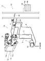
- FIG. 1 is a schematic configuration diagram of a cooling water drop prevention system according to an embodiment of the present invention
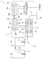
- FIG. 1 is a schematic configuration diagram of a pump unit according to an embodiment of the present invention
- FIG. 1 is a schematic configuration diagram of a pump unit according to an embodiment of the present invention
- FIG. 1 shows a spot welder 10 to which a cooling water drop prevention system 1 according to an embodiment of the present invention is connected.
- the spot welder 10 is used, for example, to assemble a plurality of pressed parts (not shown) on an automobile production line by spot welding, and includes a welding gun 11 having a substantially C shape when viewed from the front. ing.
- a pair of thin rod-shaped shanks 11a are provided at the tip of the welding gun 11 so as to face each other, and one shank 11a side portion can approach and separate from the other shank 11a.
- a substantially bell-shaped electrode 12 is detachably attached to the tip of each shank 11a. After the shank 11a side portion is brought closer to the other shank 11a and the object to be welded is sandwiched between the two electrodes 12 and pressurized, the object to be welded is spot-welded by passing an electric current between the two electrodes 12. It's becoming
- a cooling unit 13 for cooling the electrodes 12 is connected to the welding gun 11 .
- the cooling unit 13 includes a unit main body 14 having a pump 14a for circulating cooling water and a tank 14b for storing the cooling water, and a cooling water supply pipe 15 (cooling water supply passage) extending from the unit main body 14 to each electrode 12. and a cooling water discharge pipe 16 (cooling water discharge passage) extending from each electrode 12 to the unit main body 14, and by operating the pump 14a, the cooling water in the tank 14b is discharged through the cooling water supply pipe 15 and the cooling water discharge pipe. 16 to circulate inside each electrode 12 to cool each electrode 12 .
- the cooling water drop prevention system 1 includes a first stop valve 2 provided in the middle of the cooling water supply pipe 15 and a second stop valve 3 provided in the middle of the cooling water discharge pipe 16.
- the stop valve 2 can stop the supply of cooling water to the inside of the electrode 12
- the second stop valve 3 can stop the discharge of cooling water from the electrode 12 .
- One end of the first pipe 4 is connected to the cooling water supply pipe 15 on the welding gun 11 side of the first stop valve 2 .
- one end of the second pipe 5 is connected to the cooling water discharge pipe 16 closer to the welding gun 11 than the second stop valve 3 , and is farther from the welding gun 11 than the second stop valve 3 of the cooling water discharge pipe 16 .
- One end of the drain pipe 6 is connected to the side.
- a pump unit 7 is connected to the other ends of the first pipe 4 , the second pipe 5 and the drain pipe 6 .
- the pump unit 7 is provided with a box-shaped body case 70. Inside the body case 70, as shown in FIG. 1 connecting pipe 71 and a second connecting pipe 72 connecting the other end of the second pipe 5 and the other end of the drain pipe 6 are arranged.
- a pair of first check valves 73 for allowing cooling water to pass only from the first pipe 4 side to the drain pipe 6 side in the first connecting pipe 71 are arranged in the cooling water passing direction. are set consecutively.
- a pair of second check valves 74 for allowing cooling water to pass only from the second pipe 5 side to the drain pipe 6 side in the second connecting pipe 72 are arranged in the cooling water passing direction. are set consecutively.
- a cylinder 75 having a guide hole 75a at one end, and the inside of the cylinder 75 is divided into a first space S1 on one side in the cylinder center line direction and a second space S2 on the other side.
- a partition plate 76 and a guide rod 77 slidably inserted into the guide hole 75 a are provided, and one end of the guide rod 77 is connected to the partition plate 76 .
- a double-acting air cylinder 78 is arranged on the other side of the cylinder body 75 in the cylinder centerline direction, and the air cylinder 78 is connected to an air supply source via a solenoid valve 79 .
- a piston rod 78 a of the air cylinder 78 is positioned on the center line of the cylinder 75 and connected to the other end of the guide rod 77 . It is made to slide along the line.
- first connecting pipe 71 and the cylindrical body 75 Between the first connecting pipe 71 and the cylindrical body 75, one end is connected to the first space S1 and the other end is connected between the two first check valves 73 in the first connecting pipe 71.
- 1 suction/discharge pipe 7a is routed between the second connecting pipe 72 and the cylindrical body 75, one end of which is connected to the second space S2, and the other end of which is connected to the second space S2 of the second connecting pipe 72.
- a second suction/discharge pipe 7b connected between the check valves 74 is arranged.
- a control unit (not shown) activates the first stop valve 2 and the second stop valve 3 to cause the inside of the electrode 12 to After stopping the circulation of the cooling water, the pump unit 7 is activated to operate the air cylinder 78 .
- the partition plate 76 moves together with the guide rod 77 sliding to one side to widen the first space S1 and narrow the second space S2. Then, the two first check valves 73 allow the cooling water in the cooling water supply pipe 15 closer to the welding gun 11 than the first stop valve 2 to flow into the first space S1. It is sucked through the suction/discharge pipe 7a.
- the partition plate 76 moves together with the guide rod 77 sliding to the other side to widen the second space S2.
- the first space S1 is narrowed.
- the two second check valves 74 allow the cooling water in the cooling water discharge pipe 16 closer to the welding gun 11 than the second stop valve 3 to flow into the second space S2.
- the cooling water accumulated in the first space S1 by the two first check valves 73 flows through the first suction/discharge pipe 7a, the first connecting pipe 71, and the drain pipe 6.
- the cooling water is discharged to a side farther from the welding gun 11 than the second stop valve 3 in the cooling water discharge pipe 16 .
- the partition plate 76 is moved together with the guide rod 77 sliding to one side to widen the first space S1. 2. Narrow the space S2. Then, the two first check valves 73 allow the cooling water in the cooling water supply pipe 15 closer to the welding gun 11 than the first stop valve 2 to flow into the first space S1. While being sucked through the suction/discharge pipe 7a, the cooling water accumulated in the second space S2 by the two second check valves 74 flows through the second suction/discharge pipe 7b, the second connecting pipe 72, and the drain pipe 6. The cooling water is discharged to a side farther from the welding gun 11 than the second stop valve 3 in the cooling water discharge pipe 16 .
- the pump unit 7 can discharge the cooling water sucked up from the first pipe 4 and the second pipe 5 to the drain pipe 6.
- the cooling water that accumulates on the welding gun 11 side of the cooling water supply pipe 15 rather than the first stop valve 2 flows through the first pipe 4 to the pump unit 7.
- the cooling water accumulated on the welding gun 11 side of the cooling water discharge pipe 16 with respect to the second stop valve 3 is sucked up by the pump unit 7 via the second pipe 5 .
- the cooling water sucked up by the pump unit 7 is sequentially returned through the drain pipe 6 to the side of the cooling water discharge pipe 16 farther from the welding gun 11 than the second stop valve 3 .
- the returned cooling water is discharged as it is without moving toward the welding gun 11 by the second stop valve 3 .
- the cooling water that accumulates in the entire region of the cooling water supply pipe 15 closer to the welding gun 11 than the first stop valve 2 is. Since all of the water and all of the cooling water accumulated in the entire area on the side of the welding gun 11 from the second stop valve 3 in the cooling water discharge pipe 16 can be removed, there is no influence on the scale and type of equipment. It is possible to reliably prevent cooling water from dropping from the tip of the welding gun 11 during the replacement work of the electrode 12 .
- the cooling water in the cooling water supply pipe 15 and the cooling water discharge pipe 16 is sucked up using the pump unit 7 that sucks up the cooling water while reciprocating the partition plate 76 inside the cylindrical body 75 .
- pump unit 7 that sucks up the cooling water while reciprocating the partition plate 76 inside the cylindrical body 75 .
- other types of pump units may be used as long as the cooling water can be sucked up from the first pipe 4 and the second pipe 5 and discharged to the drain pipe 6 .
- the air cylinder 78 is used as the fluid pressure cylinder that activates the pump unit 7, but other types of fluid pressure cylinders may be used.
- the present invention is a cooling water drop prevention system that is connected to a spot welder and prevents cooling water for cooling the electrode from dropping from the tip of the welding gun when an electrode is removed from the tip of the welding gun during electrode replacement work. Suitable for
- Cooling water drop prevention system 1 cooling water drop prevention system 2 first stop valve 3 second stop valve 4 first pipe 5 second pipe 6 drain pipe 7 pump unit 7a first suction/discharge pipe 7b second suction/discharge pipe 10 spot welder 11 welding Gun 11a Shank 12 Electrode 15 Cooling water supply pipe (cooling water supply passage) 16 cooling water discharge pipe (cooling water discharge passage) 71 First connecting pipe 72 Second connecting pipe 73 First check valve 74 Second check valve 75 Cylindrical body 75a Guide hole 76 Partition plate 77 Guide rod 78 Air cylinder (fluid pressure cylinder) S1 First space S2 Second space
Landscapes
- Engineering & Computer Science (AREA)
- Mechanical Engineering (AREA)
- Physics & Mathematics (AREA)
- Optics & Photonics (AREA)
- Resistance Welding (AREA)
- Branch Pipes, Bends, And The Like (AREA)
Abstract
Description
2 第1ストップバルブ
3 第2ストップバルブ
4 第1配管
5 第2配管
6 ドレン配管
7 ポンプユニット
7a 第1吸込吐出用管
7b 第2吸込吐出用管
10 スポット溶接機
11 溶接ガン
11a シャンク
12 電極
15 冷却水供給配管(冷却水供給通路)
16 冷却水排出配管(冷却水排出通路)
71 第1接続管
72 第2接続管
73 第1逆止弁
74 第2逆止弁
75 筒体
75a ガイド孔
76 仕切板
77 ガイド棒
78 エアシリンダ(流体圧シリンダ)
S1 第1空間
S2 第2空間
Claims (2)
- スポット溶接機の溶接ガン先端に装着された電極の内部に冷却水供給通路及び冷却水排出通路を介して循環させる冷却水が前記溶接ガンの先端から前記電極を取り外した際に落下するのを防止する冷却水落下防止システムであって、
前記冷却水供給通路の中途部に設けられ、前記電極内部への冷却水の供給を停止可能な第1ストップバルブと、
前記冷却水排出通路の中途部に設けられ、前記電極内部からの冷却水の排出を停止可能な第2ストップバルブと、
一端が前記冷却水供給通路の前記第1ストップバルブよりも前記溶接ガン側に接続された第1配管と、
一端が前記冷却水排出通路の前記第2ストップバルブよりも前記溶接ガン側に接続された第2配管と、
一端が前記冷却水排出通路の前記第2ストップバルブよりも前記溶接ガンから遠い側に接続されたドレン配管と、
前記第1配管、第2配管及びドレン配管の各他端が接続され、前記第1及び第2配管から吸い上げる冷却水を前記ドレン配管へと排出可能なポンプユニットとを備えていることを特徴とする冷却水落下防止システム。 - 請求項1に記載の冷却水落下防止システムにおいて、
前記ポンプユニットは、前記第1配管及びドレン配管の他端同士を繋ぐ第1接続管と、前記第2配管及びドレン配管の他端同士を繋ぐ第2接続管と、前記第1接続管の中途部に連続して設けられ、当該第1接続管において前記第1配管側から前記ドレン配管側にのみ冷却水を通過させる一対の第1逆止弁と、前記第2接続管の中途部に連続して設けられ、当該第2接続管において前記第2配管側から前記ドレン配管側にのみ冷却水を通過させる一対の第2逆止弁と、一端にガイド孔を有する筒体と、該筒体の内部を筒中心線方向一側の第1空間と他側の第2空間とに仕切る仕切板と、前記ガイド孔にスライド可能に嵌挿され、一端が前記仕切板に接続されたガイド棒と、該ガイド棒の他端に接続され、且つ、当該ガイド棒をスライドさせる流体圧シリンダと、一端が前記第1空間に接続される一方、他端が前記第1接続管の両第1逆止弁の間に接続された第1吸込吐出用管と、一端が前記第2空間に接続される一方、他端が前記第2接続管の両第2逆止弁の間に接続された第2吸込吐出用管とを備えていることを特徴とする冷却水落下防止システム。
Priority Applications (6)
| Application Number | Priority Date | Filing Date | Title |
|---|---|---|---|
| EP21921305.5A EP4265362A4 (en) | 2021-01-20 | 2021-12-17 | Coolant drop prevention system |
| KR1020237023195A KR102871147B1 (ko) | 2021-01-20 | 2021-12-17 | 냉각수 낙하 방지 시스템 |
| MX2023007585A MX2023007585A (es) | 2021-01-20 | 2021-12-17 | Sistema de prevencion de caida de refrigerante. |
| CA3203516A CA3203516A1 (en) | 2021-01-20 | 2021-12-17 | Coolant drop prevention system |
| CN202180090514.9A CN116806181B (en) | 2021-01-20 | 2021-12-17 | Coolant drip prevention system |
| US18/222,965 US20230356319A1 (en) | 2021-01-20 | 2023-07-17 | Coolant drop prevention system |
Applications Claiming Priority (2)
| Application Number | Priority Date | Filing Date | Title |
|---|---|---|---|
| JP2021007179A JP7606213B2 (ja) | 2021-01-20 | 2021-01-20 | 冷却水落下防止システム |
| JP2021-007179 | 2021-01-20 |
Related Child Applications (1)
| Application Number | Title | Priority Date | Filing Date |
|---|---|---|---|
| US18/222,965 Continuation US20230356319A1 (en) | 2021-01-20 | 2023-07-17 | Coolant drop prevention system |
Publications (1)
| Publication Number | Publication Date |
|---|---|
| WO2022158204A1 true WO2022158204A1 (ja) | 2022-07-28 |
Family
ID=82548257
Family Applications (1)
| Application Number | Title | Priority Date | Filing Date |
|---|---|---|---|
| PCT/JP2021/046828 Ceased WO2022158204A1 (ja) | 2021-01-20 | 2021-12-17 | 冷却水落下防止システム |
Country Status (7)
| Country | Link |
|---|---|
| US (1) | US20230356319A1 (ja) |
| EP (1) | EP4265362A4 (ja) |
| JP (1) | JP7606213B2 (ja) |
| KR (1) | KR102871147B1 (ja) |
| CA (1) | CA3203516A1 (ja) |
| MX (1) | MX2023007585A (ja) |
| WO (1) | WO2022158204A1 (ja) |
Cited By (1)
| Publication number | Priority date | Publication date | Assignee | Title |
|---|---|---|---|---|
| DE102022212407A1 (de) * | 2022-11-21 | 2024-05-23 | Klaus Günther GmbH | Vorrichtung zur Kühlmittelversorgung und Kühlwassersystem |
Citations (4)
| Publication number | Priority date | Publication date | Assignee | Title |
|---|---|---|---|---|
| JPH02118684U (ja) * | 1989-03-07 | 1990-09-25 | ||
| JP2008183578A (ja) * | 2007-01-29 | 2008-08-14 | Shinko Kiki Kk | 電気抵抗スポット溶接機の冷却水の止水方法及び止水装置、電気抵抗スポット溶接機 |
| JP2017528325A (ja) * | 2014-09-09 | 2017-09-28 | プロテウス・インダストリーズ・インコーポレーテッド | 冷却液引き戻しのためのシステムおよび方法 |
| WO2020087959A1 (zh) | 2018-11-02 | 2020-05-07 | 广州市极动焊接机械有限公司 | 冷却水防落装置 |
Family Cites Families (4)
| Publication number | Priority date | Publication date | Assignee | Title |
|---|---|---|---|---|
| DE3316868A1 (de) * | 1983-05-07 | 1984-05-17 | Daimler-Benz Ag, 7000 Stuttgart | Kuehlwasserabsaugvorrichtung fuer widerstandsschweissanlagen |
| JP2010069493A (ja) * | 2008-09-17 | 2010-04-02 | Central Motor Co Ltd | 循環式スポット溶接ガン冷却システム |
| KR101856154B1 (ko) * | 2016-12-26 | 2018-05-09 | (주)에이트론 | 용접건 냉각수 차단장치 |
| DE202017107534U1 (de) | 2017-12-11 | 2019-04-30 | PAS AIR Automatisierung, Projektierung und Steuerungstechnik GmbH & Co. KG | Kühlmedien-Absaugvorrichtung für Schweißzangen |
-
2021
- 2021-01-20 JP JP2021007179A patent/JP7606213B2/ja active Active
- 2021-12-17 KR KR1020237023195A patent/KR102871147B1/ko active Active
- 2021-12-17 CA CA3203516A patent/CA3203516A1/en active Pending
- 2021-12-17 EP EP21921305.5A patent/EP4265362A4/en active Pending
- 2021-12-17 MX MX2023007585A patent/MX2023007585A/es unknown
- 2021-12-17 WO PCT/JP2021/046828 patent/WO2022158204A1/ja not_active Ceased
-
2023
- 2023-07-17 US US18/222,965 patent/US20230356319A1/en active Pending
Patent Citations (4)
| Publication number | Priority date | Publication date | Assignee | Title |
|---|---|---|---|---|
| JPH02118684U (ja) * | 1989-03-07 | 1990-09-25 | ||
| JP2008183578A (ja) * | 2007-01-29 | 2008-08-14 | Shinko Kiki Kk | 電気抵抗スポット溶接機の冷却水の止水方法及び止水装置、電気抵抗スポット溶接機 |
| JP2017528325A (ja) * | 2014-09-09 | 2017-09-28 | プロテウス・インダストリーズ・インコーポレーテッド | 冷却液引き戻しのためのシステムおよび方法 |
| WO2020087959A1 (zh) | 2018-11-02 | 2020-05-07 | 广州市极动焊接机械有限公司 | 冷却水防落装置 |
Non-Patent Citations (1)
| Title |
|---|
| See also references of EP4265362A4 |
Cited By (1)
| Publication number | Priority date | Publication date | Assignee | Title |
|---|---|---|---|---|
| DE102022212407A1 (de) * | 2022-11-21 | 2024-05-23 | Klaus Günther GmbH | Vorrichtung zur Kühlmittelversorgung und Kühlwassersystem |
Also Published As
| Publication number | Publication date |
|---|---|
| KR20230117214A (ko) | 2023-08-07 |
| US20230356319A1 (en) | 2023-11-09 |
| KR102871147B1 (ko) | 2025-10-14 |
| EP4265362A1 (en) | 2023-10-25 |
| JP2022111624A (ja) | 2022-08-01 |
| CN116806181A (zh) | 2023-09-26 |
| JP7606213B2 (ja) | 2024-12-25 |
| MX2023007585A (es) | 2023-07-07 |
| CA3203516A1 (en) | 2022-07-28 |
| EP4265362A4 (en) | 2024-07-03 |
Similar Documents
| Publication | Publication Date | Title |
|---|---|---|
| WO2022158204A1 (ja) | 冷却水落下防止システム | |
| US20210162529A1 (en) | Device for blocking cooling water of weld gun | |
| DE19918560B4 (de) | Luftzuführ- und Abführsystem für pneumatisches Werkzeug | |
| CA2530144A1 (en) | Apparatus for flushing, replacing fluid and bleeding hydraulic systems | |
| KR20200007041A (ko) | 실린더 구동용 매니폴드 장치 및 실린더 구동장치 | |
| JP2010064165A (ja) | 深穴加工装置 | |
| JP7132361B2 (ja) | 工作機械 | |
| JP2007290319A (ja) | 給油装置、印刷機及び給油方法、並びに給油用コンピュータプログラム | |
| CN116806181B (en) | Coolant drip prevention system | |
| CN109262126B (zh) | 冷却水防落装置 | |
| KR101423201B1 (ko) | 스폿 용접건의 냉각수 순환장치 | |
| DE102019133576B3 (de) | Kompressor und Verfahren zur Förderung und Verdichtung eines Förderfluids in ein Zielsystem | |
| JPH09229007A (ja) | 増圧式シリンダ装置 | |
| US8210318B2 (en) | Minimum oil machining system | |
| JPWO2019130464A1 (ja) | 空気抜き装置、潤滑装置、および、空気抜き方法 | |
| KR101684394B1 (ko) | 진공실린더장치 | |
| JP4613624B2 (ja) | クーラント供給装置 | |
| EP0600168B1 (de) | Verdrängerpumpe | |
| JP2015100848A (ja) | 打抜き機械の工具内に収容された加工工具の破損を監視するための監視装置および方法 | |
| DE966654C (de) | Kaeltemittelverdichter | |
| JP2006336857A (ja) | シリンダ | |
| KR20160032873A (ko) | 용접건 냉각수 차단장치 | |
| JP2001072199A (ja) | トルコンオイル交換装置 | |
| KR200412940Y1 (ko) | 이동식 유압유 플러싱 장치 | |
| DE102018003507B3 (de) | Linearwirkendes Elektropumpenaggregat mit einem Balg und Verfahren zum Betrieb desselben |
Legal Events
| Date | Code | Title | Description |
|---|---|---|---|
| 121 | Ep: the epo has been informed by wipo that ep was designated in this application |
Ref document number: 21921305 Country of ref document: EP Kind code of ref document: A1 |
|
| WWE | Wipo information: entry into national phase |
Ref document number: MX/A/2023/007585 Country of ref document: MX |
|
| ENP | Entry into the national phase |
Ref document number: 3203516 Country of ref document: CA |
|
| ENP | Entry into the national phase |
Ref document number: 20237023195 Country of ref document: KR Kind code of ref document: A |
|
| WWE | Wipo information: entry into national phase |
Ref document number: 202180090514.9 Country of ref document: CN |
|
| ENP | Entry into the national phase |
Ref document number: 2021921305 Country of ref document: EP Effective date: 20230717 |
|
| WWE | Wipo information: entry into national phase |
Ref document number: 202317052609 Country of ref document: IN |
|
| NENP | Non-entry into the national phase |
Ref country code: DE |