WO2022158375A1 - 非水電解質二次電池 - Google Patents
非水電解質二次電池 Download PDFInfo
- Publication number
- WO2022158375A1 WO2022158375A1 PCT/JP2022/001019 JP2022001019W WO2022158375A1 WO 2022158375 A1 WO2022158375 A1 WO 2022158375A1 JP 2022001019 W JP2022001019 W JP 2022001019W WO 2022158375 A1 WO2022158375 A1 WO 2022158375A1
- Authority
- WO
- WIPO (PCT)
- Prior art keywords
- negative electrode
- mixture layer
- electrode mixture
- graphite particles
- aqueous electrolyte
- Prior art date
- Legal status (The legal status is an assumption and is not a legal conclusion. Google has not performed a legal analysis and makes no representation as to the accuracy of the status listed.)
- Ceased
Links
Images
Classifications
-
- H—ELECTRICITY
- H01—ELECTRIC ELEMENTS
- H01M—PROCESSES OR MEANS, e.g. BATTERIES, FOR THE DIRECT CONVERSION OF CHEMICAL ENERGY INTO ELECTRICAL ENERGY
- H01M4/00—Electrodes
- H01M4/02—Electrodes composed of, or comprising, active material
- H01M4/13—Electrodes for accumulators with non-aqueous electrolyte, e.g. for lithium-accumulators; Processes of manufacture thereof
- H01M4/133—Electrodes based on carbonaceous material, e.g. graphite-intercalation compounds or CFx
-
- H—ELECTRICITY
- H01—ELECTRIC ELEMENTS
- H01M—PROCESSES OR MEANS, e.g. BATTERIES, FOR THE DIRECT CONVERSION OF CHEMICAL ENERGY INTO ELECTRICAL ENERGY
- H01M10/00—Secondary cells; Manufacture thereof
- H01M10/05—Accumulators with non-aqueous electrolyte
- H01M10/052—Li-accumulators
- H01M10/0525—Rocking-chair batteries, i.e. batteries with lithium insertion or intercalation in both electrodes; Lithium-ion batteries
-
- H—ELECTRICITY
- H01—ELECTRIC ELEMENTS
- H01M—PROCESSES OR MEANS, e.g. BATTERIES, FOR THE DIRECT CONVERSION OF CHEMICAL ENERGY INTO ELECTRICAL ENERGY
- H01M4/00—Electrodes
- H01M4/02—Electrodes composed of, or comprising, active material
- H01M4/13—Electrodes for accumulators with non-aqueous electrolyte, e.g. for lithium-accumulators; Processes of manufacture thereof
- H01M4/134—Electrodes based on metals, Si or alloys
-
- H—ELECTRICITY
- H01—ELECTRIC ELEMENTS
- H01M—PROCESSES OR MEANS, e.g. BATTERIES, FOR THE DIRECT CONVERSION OF CHEMICAL ENERGY INTO ELECTRICAL ENERGY
- H01M4/00—Electrodes
- H01M4/02—Electrodes composed of, or comprising, active material
- H01M4/36—Selection of substances as active materials, active masses, active liquids
- H01M4/362—Composites
- H01M4/364—Composites as mixtures
-
- H—ELECTRICITY
- H01—ELECTRIC ELEMENTS
- H01M—PROCESSES OR MEANS, e.g. BATTERIES, FOR THE DIRECT CONVERSION OF CHEMICAL ENERGY INTO ELECTRICAL ENERGY
- H01M4/00—Electrodes
- H01M4/02—Electrodes composed of, or comprising, active material
- H01M4/36—Selection of substances as active materials, active masses, active liquids
- H01M4/38—Selection of substances as active materials, active masses, active liquids of elements or alloys
- H01M4/386—Silicon or alloys based on silicon
-
- H—ELECTRICITY
- H01—ELECTRIC ELEMENTS
- H01M—PROCESSES OR MEANS, e.g. BATTERIES, FOR THE DIRECT CONVERSION OF CHEMICAL ENERGY INTO ELECTRICAL ENERGY
- H01M4/00—Electrodes
- H01M4/02—Electrodes composed of, or comprising, active material
- H01M4/36—Selection of substances as active materials, active masses, active liquids
- H01M4/48—Selection of substances as active materials, active masses, active liquids of inorganic oxides or hydroxides
- H01M4/485—Selection of substances as active materials, active masses, active liquids of inorganic oxides or hydroxides of mixed oxides or hydroxides for inserting or intercalating light metals, e.g. LiTi2O4 or LiTi2OxFy
-
- H—ELECTRICITY
- H01—ELECTRIC ELEMENTS
- H01M—PROCESSES OR MEANS, e.g. BATTERIES, FOR THE DIRECT CONVERSION OF CHEMICAL ENERGY INTO ELECTRICAL ENERGY
- H01M4/00—Electrodes
- H01M4/02—Electrodes composed of, or comprising, active material
- H01M4/36—Selection of substances as active materials, active masses, active liquids
- H01M4/58—Selection of substances as active materials, active masses, active liquids of inorganic compounds other than oxides or hydroxides, e.g. sulfides, selenides, tellurides, halogenides or LiCoFy; of polyanionic structures, e.g. phosphates, silicates or borates
- H01M4/583—Carbonaceous material, e.g. graphite-intercalation compounds or CFx
- H01M4/587—Carbonaceous material, e.g. graphite-intercalation compounds or CFx for inserting or intercalating light metals
-
- H—ELECTRICITY
- H01—ELECTRIC ELEMENTS
- H01M—PROCESSES OR MEANS, e.g. BATTERIES, FOR THE DIRECT CONVERSION OF CHEMICAL ENERGY INTO ELECTRICAL ENERGY
- H01M4/00—Electrodes
- H01M4/02—Electrodes composed of, or comprising, active material
- H01M4/64—Carriers or collectors
- H01M4/66—Selection of materials
- H01M4/661—Metal or alloys, e.g. alloy coatings
-
- H—ELECTRICITY
- H01—ELECTRIC ELEMENTS
- H01M—PROCESSES OR MEANS, e.g. BATTERIES, FOR THE DIRECT CONVERSION OF CHEMICAL ENERGY INTO ELECTRICAL ENERGY
- H01M4/00—Electrodes
- H01M4/02—Electrodes composed of, or comprising, active material
- H01M2004/021—Physical characteristics, e.g. porosity, surface area
-
- H—ELECTRICITY
- H01—ELECTRIC ELEMENTS
- H01M—PROCESSES OR MEANS, e.g. BATTERIES, FOR THE DIRECT CONVERSION OF CHEMICAL ENERGY INTO ELECTRICAL ENERGY
- H01M4/00—Electrodes
- H01M4/02—Electrodes composed of, or comprising, active material
- H01M2004/026—Electrodes composed of, or comprising, active material characterised by the polarity
- H01M2004/027—Negative electrodes
-
- Y—GENERAL TAGGING OF NEW TECHNOLOGICAL DEVELOPMENTS; GENERAL TAGGING OF CROSS-SECTIONAL TECHNOLOGIES SPANNING OVER SEVERAL SECTIONS OF THE IPC; TECHNICAL SUBJECTS COVERED BY FORMER USPC CROSS-REFERENCE ART COLLECTIONS [XRACs] AND DIGESTS
- Y02—TECHNOLOGIES OR APPLICATIONS FOR MITIGATION OR ADAPTATION AGAINST CLIMATE CHANGE
- Y02E—REDUCTION OF GREENHOUSE GAS [GHG] EMISSIONS, RELATED TO ENERGY GENERATION, TRANSMISSION OR DISTRIBUTION
- Y02E60/00—Enabling technologies; Technologies with a potential or indirect contribution to GHG emissions mitigation
- Y02E60/10—Energy storage using batteries
Definitions
- the present disclosure relates to non-aqueous electrolyte secondary batteries.
- Non-aqueous electrolyte secondary batteries that use graphite particles as a negative electrode active material are widely used as high energy density secondary batteries.
- the packing density of the negative electrode mixture layer is increased in order to increase the capacity of the battery, the voids between the graphite particles become smaller, and the permeability of the non-aqueous electrolyte into the negative electrode mixture layer deteriorates.
- the battery capacity decreases.
- Patent Document 1 discloses an electrode in which a mixed layer containing an active material and an insulating oxide such as alumina or titanium oxide is formed on the surface of a mixture layer from the viewpoint of improving the wettability of the electrode surface. disclosed.
- an object of the present disclosure is to provide a non-aqueous electrolyte secondary battery that suppresses a decrease in battery capacity due to repeated charging and discharging.
- a nonaqueous electrolyte secondary battery includes a positive electrode, a negative electrode, and a nonaqueous electrolyte.
- the negative electrode includes a negative electrode current collector and a negative electrode mixture formed on the surface of the negative electrode current collector.
- the negative electrode mixture layer includes a first negative electrode mixture layer facing the negative electrode current collector and a second negative electrode mixture layer laminated on the surface of the first negative electrode mixture layer.
- the agent layer contains graphite particles and a high dielectric material having a higher dielectric constant than the graphite particles, and the porosity between the graphite particles in the second negative electrode mixture layer is equal to the voids between the graphite particles in the first negative electrode mixture layer.
- the content of the high dielectric material in the first negative electrode mixture layer is higher than the content of the high dielectric material in the second negative electrode mixture layer.
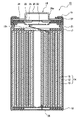
- FIG. 1 is an axial cross-sectional view of a cylindrical secondary battery that is an example of an embodiment
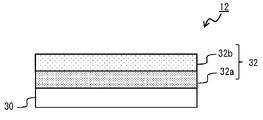
- FIG. 1 is a cross-sectional view of a negative electrode in one example of an embodiment
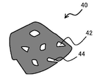
- FIG. It is a schematic diagram showing a cross section of a graphite particle in an example of the embodiment.
- FIG. 1 is an axial cross-sectional view of a cylindrical secondary battery 10 that is an example of an embodiment.
- an electrode body 14 and a non-aqueous electrolyte (not shown) are housed in an exterior body 15 .
- the electrode body 14 has a wound structure in which the positive electrode 11 and the negative electrode 12 are wound with the separator 13 interposed therebetween.
- the sealing member 16 side will be referred to as "upper”
- the bottom side of the outer package 15 will be referred to as "lower”.
- the inside of the secondary battery 10 is hermetically sealed by closing the opening end of the exterior body 15 with the sealing body 16 .
- Insulating plates 17 and 18 are provided above and below the electrode body 14, respectively.
- the positive electrode lead 19 extends upward through the through hole of the insulating plate 17 and is welded to the lower surface of the filter 22 which is the bottom plate of the sealing member 16 .
- the cap 26, which is the top plate of the sealing member 16 electrically connected to the filter 22, serves as a positive electrode terminal.
- the negative electrode lead 20 passes through the through hole of the insulating plate 18 , extends to the bottom side of the exterior body 15 , and is welded to the bottom inner surface of the exterior body 15 .
- the exterior body 15 becomes a negative electrode terminal.
- the negative electrode lead 20 When the negative electrode lead 20 is installed at the terminal end, the negative electrode lead 20 extends through the outside of the insulating plate 18 toward the bottom of the package 15 and is welded to the inner surface of the bottom of the package 15 .
- the exterior body 15 is, for example, a bottomed cylindrical metal exterior can.
- a gasket 27 is provided between the exterior body 15 and the sealing body 16 to ensure hermetic sealing of the inside of the secondary battery 10 .
- the exterior body 15 has a grooved portion 21 that supports the sealing body 16 and is formed, for example, by pressing the side portion from the outside.
- the grooved portion 21 is preferably annularly formed along the circumferential direction of the exterior body 15 and supports the sealing body 16 via a gasket 27 on its upper surface.
- the sealing body 16 has a filter 22, a lower valve body 23, an insulating member 24, an upper valve body 25, and a cap 26 which are stacked in order from the electrode body 14 side.
- Each member constituting the sealing member 16 has, for example, a disk shape or a ring shape, and each member other than the insulating member 24 is electrically connected to each other.
- the lower valve body 23 and the upper valve body 25 are connected to each other at their central portions, and an insulating member 24 is interposed between their peripheral edge portions.
- the positive electrode 11, the negative electrode 12, the separator 13, and the non-aqueous electrolyte that constitute the secondary battery 10, in particular the negative electrode mixture layer 32 that constitutes the negative electrode 12, will be described in detail below.
- FIG. 2 is a cross-sectional view of the negative electrode 12 that is an example of an embodiment.
- the negative electrode 12 includes a negative electrode current collector 30 and a negative electrode mixture layer 32 formed on the surface of the negative electrode current collector 30 .
- the negative electrode mixture layer 32 includes a first negative electrode mixture layer 32a facing the negative electrode current collector 30 and a second negative electrode mixture layer 32b laminated on the surface of the first negative electrode mixture layer 32a.
- the thickness of the first negative electrode mixture layer 32a and the thickness of the second negative electrode mixture layer 32b may be the same or different.
- the thickness ratio between the first negative electrode mixture layer 32a and the second negative electrode mixture layer 32b is, for example, 3:7 to 7:3, preferably 4:6 to 6:4, and 5:5 to 6:4. is more preferred.
- the negative electrode current collector 30 for example, a foil of a metal such as copper that is stable in the potential range of the negative electrode, a film having the metal on the surface layer, or the like is used.
- the thickness of the negative electrode current collector 30 is, for example, 5 ⁇ m to 30 ⁇ m.
- the negative electrode mixture layer 32 contains graphite particles as a negative electrode active material.
- graphite particles include natural graphite and artificial graphite. Artificial graphite is preferable in terms of ease of adjustment of internal porosity, which will be described later.
- the interplanar spacing (d 002 ) of the (002) plane of the graphite particles according to the X-ray wide-angle diffraction method is, for example, preferably 0.3354 nm or more, more preferably 0.3357 nm or more, and 0.340 nm. It is preferably less than 0.338 nm, more preferably 0.338 nm or less.
- the crystallite size (Lc(002)) of the graphite particles obtained by the X-ray diffraction method is, for example, preferably 5 nm or more, more preferably 10 nm or more, and 300 nm or less. It is preferably 200 nm or less, more preferably 200 nm or less.
- FIG. 3 is a schematic diagram showing a cross section of the graphite particles 40.
- FIG. 3 in a cross-sectional view of the graphite particle 40, the graphite particle 40 has closed voids 42 that are not connected from the inside of the particle to the particle surface (hereinafter referred to as internal voids 42) and voids that are connected from the inside of the particle to the particle surface. and a gap 44 (hereinafter referred to as an external gap 44).
- the porosity between graphite particles in the second negative electrode mixture layer 32b is higher than the porosity between graphite particles in the first negative electrode mixture layer 32a.
- the ratio (S2/S1) of the void ratio (S2) between graphite particles in the second negative electrode mixture layer 32b to the void ratio (S1) between graphite particles in the first negative electrode mixture layer 32a is 1 ⁇ S2/S1 ⁇ 2 is preferable, 1.1 ⁇ S2/S1 ⁇ 1.7 is more preferable, and 1.1 ⁇ S2/S1 ⁇ 1.5 is particularly preferable.
- S2/S1 ⁇ 1 the permeability of the non-aqueous electrolyte in the second negative electrode mixture layer 32b becomes poor, and the battery capacity decreases due to repeated charging and discharging.
- the void ratio between graphite particles is a two-dimensional value obtained from the ratio of the area of voids between graphite particles to the cross-sectional area of the negative electrode mixture layer 32 .
- S2/S1 calculates the void ratio (S1) between graphite particles in the first negative electrode mixture layer 32a and the void ratio (S2) between graphite particles in the second negative electrode mixture layer 32b in the following procedure. It is required by
- ⁇ Method for measuring porosity between graphite particles> Exposing a cross section of the negative electrode mixture layer. Examples of the method for exposing the cross section include a method in which a portion of the negative electrode is cut and processed with an ion milling device (eg, IM4000PLUS manufactured by Hitachi High-Tech) to expose the cross section of the negative electrode mixture layer.
- an ion milling device eg, IM4000PLUS manufactured by Hitachi High-Tech
- Backscattered electron images of cross sections of the exposed negative electrode mixture layers are taken for each of the first negative electrode mixture layer 32a and the second negative electrode mixture layer 32b using a scanning electron microscope. The magnification for capturing the backscattered electron image is, for example, 800 times.
- the cross-sectional image obtained as described above is taken into a computer, and subjected to binarization processing using image analysis software (for example, ImageJ manufactured by the National Institutes of Health, USA) to turn the particle cross section in the cross-sectional image black, A binarized image is obtained in which voids present in the cross section of the particle are converted to white.
- image analysis software for example, ImageJ manufactured by the National Institutes of Health, USA
- a binarized image is obtained in which voids present in the cross section of the particle are converted to white.
- the internal voids 42 and the external voids 44 having a width of 3 ⁇ m or less
- the area of the voids between the graphite particles is calculated by regarding the portions other than the voids between the graphite particles as voids between the graphite particles.
- Means for adjusting the porosity between graphite particles in the first negative electrode mixture layer 32a and the second negative electrode mixture layer 32b include, for example, means for adjusting the packing density of the negative electrode mixture layer and internal porosity of the graphite particles. can be adjusted. According to the latter means, by reducing the internal porosity of the graphite particles, the porosity between the graphite particles can be reduced without reducing the packing density of the first negative electrode mixture layer 32a and the second negative electrode mixture layer 32b. can be enhanced.
- the second negative electrode mixture layer By reducing the internal porosity of the graphite particles B contained in 32b, S2/S1>1 can be satisfied.
- the graphite particles A contained in the first negative electrode mixture layer 32a can be produced, for example, as follows. Coke (precursor), which is the main raw material, is pulverized to a predetermined size, agglomerated with a binder, and further pressure-molded into a block shape, which is fired at a temperature of 2600° C. or higher to graphitize. Graphite particles A having a desired size are obtained by pulverizing and sieving the block-shaped compact after graphitization. Here, it is possible to adjust the internal porosity to be larger than that of graphite particles B, which will be described later, by adjusting the amount of the volatile component added to the block-shaped compact.
- the internal porosity of graphite particles A is preferably 8% to 20%, more preferably 10% to 18%, and particularly preferably 12% to 16%. If part of the binder added to the coke (precursor) volatilizes during firing, the binder can be used as a volatile component. Pitch is exemplified as such a binder.
- the graphite particles B contained in the second negative electrode mixture layer 32b can be produced, for example, as follows. Coke (precursor), which is the main raw material, is pulverized to a predetermined size, aggregated with a binder, fired at a temperature of 2600 ° C. or higher, graphitized, and sieved to obtain the desired Graphite particles B of size are obtained.
- the internal porosity of the graphite particles B can be adjusted by the particle size of the precursor after pulverization, the particle size of the aggregated precursor, and the like. For example, the internal porosity can be reduced by increasing the particle size of the precursor after pulverization.
- the average particle diameter of the pulverized precursor may be in the range of 12 ⁇ m to 20 ⁇ m.
- the internal porosity of the graphite particles B is preferably 5% or less, more preferably 1% to 5%, particularly preferably 3% to 5%.
- first negative electrode mixture layer 32a and the second negative electrode mixture layer 32b a method for forming the first negative electrode mixture layer 32a and the second negative electrode mixture layer 32b will be described.
- a negative electrode active material containing graphite particles A, a binder, and a solvent such as water are mixed to prepare a first negative electrode mixture slurry.
- a negative electrode active material containing graphite particles B, a binder, and a solvent such as water are mixed to prepare a second negative electrode mixture slurry.
- the second negative electrode mixture slurry is applied to both surfaces of the coating film of the first negative electrode mixture slurry and dried.
- the negative electrode mixture layer 32 can be formed by rolling the first negative electrode mixture layer 32a and the second negative electrode mixture layer 32b with rolling rollers.
- the first negative electrode mixture slurry is applied and dried, and then the second negative electrode mixture slurry is applied.
- a slurry may be applied.
- the first negative electrode mixture slurry may be applied, dried, and rolled, and then the second negative electrode mixture slurry may be applied on the first negative electrode mixture layer 32a.
- the negative electrode mixture layer 32 further contains a high dielectric material with a higher dielectric constant than graphite particles.
- the content of the high dielectric material in the first negative electrode mixture layer 32a is higher than the content of the high dielectric material in the second negative electrode mixture layer 32b. While S2/S1>1, the content of the high dielectric material in the first negative electrode mixture layer 32a is higher than the content of the high dielectric material in the second negative electrode mixture layer 32b. Since the permeability of the non-aqueous electrolyte in the opposing first negative electrode mixture layers 32 a is improved, the permeability of the non-aqueous electrolyte in the entire negative electrode mixture layer 32 is improved. This improves the charge/discharge cycle characteristics of the battery.
- the content of the high dielectric material is the ratio of the mass of the high dielectric material to the mass of the negative electrode active material.
- the high dielectric material is not particularly limited as long as it has a dielectric constant higher than that of graphite particles, and examples thereof include titanium oxide (TiO 2 ), lithium titanate (Li 2 TiO 3 ) and barium oxide (BaO).
- the high dielectric material preferably contains at least one of titanium oxide (TiO 2 ) and lithium titanate (Li 2 TiO 3 ).
- the dielectric constant of graphite particles is about 12, the dielectric constant of TiO2 is about 100, and the dielectric constant of Li2TiO3 is about 30 .
- the average particle size (D50) of the high dielectric material is, for example, 300 nm to 3 ⁇ m.
- the content of the high dielectric material in the first negative electrode mixture layer 32a is preferably 1% by mass to 10% by mass, more preferably 2% by mass, with respect to the mass of the negative electrode active material contained in the first negative electrode mixture layer 32a. % to 7% by mass, and particularly preferably 2.5% to 5% by mass. Within this range, a decrease in battery capacity can be suppressed while improving charge-discharge cycle characteristics.
- the negative electrode mixture layer 32 may further contain a Si-based material as a negative electrode active material.
- a Si-based material is a material that can reversibly absorb and release lithium ions, and functions as a negative electrode active material. Examples of Si-based materials include Si, alloys containing Si, and silicon oxides such as SiO x (where x is 0.8 to 1.6).
- a Si-based material is a negative electrode material that can improve battery capacity more than graphite particles.
- the content of the Si-based material is, for example, preferably 1% by mass to 10% by mass with respect to the mass of the negative electrode active material, from the viewpoint of improving battery capacity, suppressing deterioration of charge-discharge cycle characteristics, etc., and 3% by mass. % to 7 mass %.
- the negative electrode active material may contain the above other materials, and the content of the above other materials is preferably, for example, 10% by mass or less with respect to the mass of the negative electrode active material.
- the negative electrode mixture layer 32 may contain a binder.
- binders include fluorine-based resins, PAN, polyimide-based resins, acrylic-based resins, polyolefin-based resins, styrene-butadiene rubber (SBR), nitrile-butadiene rubber (NBR), carboxymethylcellulose (CMC), or salts thereof.
- polyacrylic acid (PAA) or salts thereof (PAA-Na, PAA-K, etc., and partially neutralized salts may also be used), polyvinyl alcohol (PVA), and the like. These may be used alone or in combination of two or more.
- the positive electrode 11 is composed of, for example, a positive electrode current collector such as a metal foil, and a positive electrode mixture layer formed on the positive electrode current collector.
- a positive electrode current collector such as a metal foil
- a positive electrode mixture layer formed on the positive electrode current collector.
- the positive electrode current collector a foil of a metal such as aluminum that is stable in the positive electrode potential range, a film having the metal on the surface layer, or the like can be used.
- the positive electrode mixture layer contains, for example, a positive electrode active material, a binder, a conductive agent, and the like.
- a positive electrode mixture slurry containing a positive electrode active material, a binder, a conductive agent, etc. is applied onto a positive electrode current collector and dried to form a positive electrode mixture layer. It can be produced by rolling.
- Examples of positive electrode active materials include lithium transition metal oxides containing transition metal elements such as Co, Mn, and Ni.
- Lithium transition metal oxides include, for example, Li x CoO 2 , Li x NiO 2 , Li x MnO 2 , Li x Co y Ni 1-y O 2 , Li x Co y M 1-y O z , Li x Ni 1- yMyOz , LixMn2O4 , LixMn2 - yMyO4 , LiMPO4 , Li2MPO4F ( M ; Na , Mg , Sc , Y , Mn, Fe, Co, Ni , Cu, Zn, Al, Cr, Pb, Sb, and B, 0 ⁇ x ⁇ 1.2, 0 ⁇ y ⁇ 0.9, 2.0 ⁇ z ⁇ 2.3).
- the positive electrode active material is Li x NiO 2 , Li x Co y Ni 1-y O 2 , Li x Ni 1- y My O z ( M; at least one of Na, Mg, Sc, Y, Mn, Fe, Co, Ni, Cu, Zn, Al, Cr, Pb, Sb, and B, 0 ⁇ x ⁇ 1.2, 0 ⁇ y ⁇ 0 .9, 2.0 ⁇ z ⁇ 2.3).
- Conductive agents include, for example, carbon black (CB), acetylene black (AB), ketjen black, carbon nanotubes (CNT), graphene, and carbon-based particles such as graphite. These may be used alone or in combination of two or more.
- binders include fluorine-based resins such as polytetrafluoroethylene (PTFE) and polyvinylidene fluoride (PVdF), polyacrylonitrile (PAN), polyimide-based resins, acrylic-based resins, and polyolefin-based resins. These may be used alone or in combination of two or more.
- fluorine-based resins such as polytetrafluoroethylene (PTFE) and polyvinylidene fluoride (PVdF), polyacrylonitrile (PAN), polyimide-based resins, acrylic-based resins, and polyolefin-based resins. These may be used alone or in combination of two or more.
- separator 13 for example, a porous sheet or the like having ion permeability and insulation is used. Specific examples of porous sheets include microporous thin films, woven fabrics, and non-woven fabrics. Suitable materials for the separator include olefin resins such as polyethylene and polypropylene, and cellulose.
- the separator 13 may be a laminate having a cellulose fiber layer and a thermoplastic resin fiber layer such as an olefin resin. Also, a multilayer separator including a polyethylene layer and a polypropylene layer may be used, and a separator 13 having a surface coated with a material such as aramid resin or ceramic may be used.
- a non-aqueous electrolyte is a liquid electrolyte (electrolytic solution) containing a non-aqueous solvent and an electrolyte salt dissolved in the non-aqueous solvent.
- non-aqueous solvents examples include esters, ethers, nitriles such as acetonitrile, amides such as dimethylformamide, and mixed solvents of two or more thereof.
- the non-aqueous solvent may contain a halogen-substituted product obtained by substituting at least part of the hydrogen atoms of these solvents with halogen atoms such as fluorine.
- esters examples include cyclic carbonates such as ethylene carbonate (EC), propylene carbonate (PC) and butylene carbonate, dimethyl carbonate (DMC), ethyl methyl carbonate (EMC), diethyl carbonate (DEC), methyl propyl carbonate. , Ethyl propyl carbonate, methyl isopropyl carbonate and other chain carbonates, ⁇ -butyrolactone, ⁇ -valerolactone and other cyclic carboxylic acid esters, methyl acetate, ethyl acetate, propyl acetate, methyl propionate (MP), ethyl propionate, etc. and chain carboxylic acid esters of.
- cyclic carbonates such as ethylene carbonate (EC), propylene carbonate (PC) and butylene carbonate, dimethyl carbonate (DMC), ethyl methyl carbonate (EMC), diethyl carbonate (DEC), methyl propyl carbonate.
- ethers examples include 1,3-dioxolane, 4-methyl-1,3-dioxolane, tetrahydrofuran, 2-methyltetrahydrofuran, propylene oxide, 1,2-butylene oxide, 1,3-dioxane, 1,4 - Cyclic ethers such as dioxane, 1,3,5-trioxane, furan, 2-methylfuran, 1,8-cineol, crown ether, 1,2-dimethoxyethane, diethyl ether, dipropyl ether, diisopropyl ether, dibutyl ether , dihexyl ether, ethyl vinyl ether, butyl vinyl ether, methyl phenyl ether, ethyl phenyl ether, butyl phenyl ether, pentyl phenyl ether, methoxytoluene, benzyl ethyl ether, diphenyl ether, dipheny
- a fluorinated cyclic carbonate such as fluoroethylene carbonate (FEC), a fluorinated chain carbonate, a fluorinated chain carboxylate such as methyl fluoropropionate (FMP), and the like.
- FEC fluoroethylene carbonate
- FMP fluorinated chain carboxylate
- FEC fluoroethylene carbonate
- FMP fluorinated chain carboxylate
- the electrolyte salt is a lithium salt.
- lithium salts include LiBF4 , LiClO4, LiPF6 , LiAsF6 , LiSbF6 , LiAlCl4 , LiSCN , LiCF3SO3 , LiCF3CO2 , Li ( P ( C2O4 ) F4 ), LiPF 6-x (C n F 2n+1 ) x (1 ⁇ x ⁇ 6, n is 1 or 2), LiB 10 Cl 10 , LiCl, LiBr, LiI, lithium chloroborane, lithium lower aliphatic carboxylate, Li 2 B 4O7 , borates such as Li( B ( C2O4 )F2), LiN( SO2CF3 ) 2 , LiN( C1F2l + 1SO2 ) ( CmF2m +1SO2 ) ⁇ l , where m is an integer of 1 or more ⁇ .
- Lithium salts may be used singly or in combination. Of these, it is preferable to use LiPF 6 from the viewpoint of ion conductivity, electrochemical stability, and the like.
- the lithium salt concentration is preferably 0.8 to 1.8 mol per 1 L of solvent.
- Example 1 [Preparation of positive electrode]
- Aluminum-containing lithium nickel cobaltate (LiNi 0.88 Co 0.09 Al 0.03 O 2 ) was used as the positive electrode active material. 100 parts by mass of the positive electrode active material, 1 part by mass of graphite as a conductive agent, and 0.9 parts by mass of polyvinylidene fluoride powder as a binder are mixed, and further N-methyl-2-pyrrolidone (NMP ) was added to prepare a positive electrode mixture slurry.
- NMP N-methyl-2-pyrrolidone
- This slurry is applied to both sides of a positive electrode current collector made of aluminum foil (thickness 15 ⁇ m) by a doctor blade method, the coating film is dried, and then the coating film is rolled with a rolling roller to A positive electrode having a positive electrode mixture layer formed thereon was produced.
- a negative electrode active material A 95 parts by mass of graphite particles A and 5 parts by mass of SiO were mixed to obtain a negative electrode active material A. Titanium oxide (TiO 2 ) having an average particle size (D50) of 500 nm was used as the high dielectric material.
- Negative electrode active material A TiO 2 : carboxymethyl cellulose (CMC): styrene-butadiene copolymer rubber (SBR) were mixed so that the mass ratio was 100:2.5:1:1, and the mixture was The mixture was kneaded in water to prepare a first negative electrode mixture slurry. Further, 95 parts by mass of graphite particles B and 5 parts by mass of SiO were mixed to obtain a negative electrode active material B.
- CMC carboxymethyl cellulose
- SBR styrene-butadiene copolymer rubber
- Negative electrode active material B carboxymethyl cellulose (CMC): styrene-butadiene copolymer rubber (SBR) were mixed so that the mass ratio was 100:1:1, and the mixture was kneaded in water to obtain a second A two-negative electrode mixture slurry was prepared.
- CMC carboxymethyl cellulose
- SBR styrene-butadiene copolymer rubber
- the first negative electrode mixture slurry was applied to both sides of a negative electrode current collector made of copper foil by a doctor blade method and dried to form a first negative electrode mixture layer. Furthermore, the second negative electrode mixture slurry was applied onto the first negative electrode mixture layer and dried to form a second negative electrode mixture layer. At this time, the coating mass ratio per unit area of the first negative electrode mixture slurry and the second negative electrode mixture slurry was set to 5:5.
- a negative electrode was produced by rolling the first negative electrode mixture layer and the second negative electrode mixture layer with a rolling roller.
- VC vinylene carbonate
- EC ethylene carbonate
- dimethyl carbonate a non-aqueous solvent obtained by mixing ethylene carbonate (EC) and dimethyl carbonate at a volume ratio of 1: 3 . It was dissolved at a concentration of 5 mol/L and used as a non-aqueous electrolyte.
- Non-aqueous electrolyte secondary battery (1) After attaching the positive electrode lead to the positive electrode current collector and attaching the negative electrode lead to the negative electrode current collector, the positive electrode and the negative electrode are wound with a separator made of a microporous polyethylene film interposed therebetween, and the winding type is obtained. An electrode body was produced. (2) Insulating plates were placed above and below the electrode assembly, the negative electrode lead was welded to the outer package, the positive electrode lead was welded to the sealing member, and the electrode assembly was housed in the outer package. (3) After injecting the non-aqueous electrolyte into the exterior body by a depressurization method, the opening of the exterior body was sealed with a sealant via a gasket to obtain a non-aqueous electrolyte secondary battery.
- Non-aqueous electrolyte 2 was prepared in the same manner as in Example 1, except that the content of TiO 2 contained in the first negative electrode mixture slurry was 3% by mass with respect to the mass of negative electrode active material A in the production of the negative electrode. made the next battery
- Non-aqueous electrolyte 2 was prepared in the same manner as in Example 1, except that the content of TiO 2 contained in the first negative electrode mixture slurry was 5% by mass with respect to the mass of negative electrode active material A in the production of the negative electrode. A following battery was produced.
- Example 1 A non-aqueous electrolyte secondary battery was fabricated in the same manner as in Example 1, except that TiO 2 was not added to the first negative electrode mixture slurry in fabricating the negative electrode.
- Table 1 summarizes the evaluation results of the capacity retention rate of the non-aqueous electrolyte secondary batteries of each example and each comparative example. Table 1 also shows the graphite particles contained in the first and second negative electrode mixture layers, the content of TiO2 in the first and second negative electrode mixture layers, and the content of TiO2 in the negative electrode mixture layer. S2/S1 is also shown.
- the battery of the example has an improved capacity retention rate compared to the battery of the comparative example.
- the porosity between graphite particles in the second negative electrode mixture layer is high, and the first negative electrode mixture layer contains titanium oxide having a dielectric constant higher than that of graphite. It is considered that the capacity retention rate was improved because the permeability of the entire layer to the electrolytic solution was improved.
Landscapes
- Chemical & Material Sciences (AREA)
- Chemical Kinetics & Catalysis (AREA)
- Electrochemistry (AREA)
- General Chemical & Material Sciences (AREA)
- Engineering & Computer Science (AREA)
- Materials Engineering (AREA)
- Composite Materials (AREA)
- Inorganic Chemistry (AREA)
- Manufacturing & Machinery (AREA)
- Battery Electrode And Active Subsutance (AREA)
- Secondary Cells (AREA)
Abstract
Description
図2は、実施形態の一例である負極12の断面図である。負極12は、負極集電体30と、負極集電体30の表面に形成された負極合剤層32とを含む。負極合剤層32は、負極集電体30に対向する第1負極合剤層32aと、第1負極合剤層32aの表面に積層された第2負極合剤層32bとを含む。第1負極合剤層32aと第2負極合剤層32bの厚みは、同じであっても相互に異なっていてもよい。第1負極合剤層32aと第2負極合剤層32bとの厚みの比率は、例えば3:7~7:3であり、4:6~6:4が好ましく、5:5~6:4がより好ましい。
(1)負極合剤層の断面を露出させる。断面を露出させる方法としては、例えば、負極の一部を切り取り、イオンミリング装置(例えば、日立ハイテク社製、IM4000PLUS)で加工し、負極合剤層の断面を露出させる方法が挙げられる。
(2)走査型電子顕微鏡を用いて、上記露出させた負極合剤層の断面の反射電子像を、第1負極合剤層32a及び第2負極合剤層32bのそれぞれについて撮影する。反射電子像を撮影する際の倍率は、例えば、800倍である。
(3)上記により得られた断面像をコンピュータに取り込み、画像解析ソフト(例えば、アメリカ国立衛生研究所製、ImageJ)を用いて二値化処理を行い、断面像内の粒子断面を黒色とし、粒子断面に存在する空隙を白色として変換した二値化処理画像を得る。
(4)第1負極合剤層32a及び第2負極合剤層32bの二値化処理画像において、各々、白色として変換された空隙のうち、内部空隙42、及び、幅3μm以下の外部空隙44を除く部分を黒鉛粒子間の空隙として、黒鉛粒子間の空隙の面積を算出する。黒鉛粒子間の空隙率は、以下の式に基づいて算出できる。
黒鉛粒子間の空隙率=黒鉛粒子間の空隙の面積/負極合剤層断面の面積×100
(5)S1及びS2は、各々、上記測定3回の平均値として求められる。
正極11は、例えば金属箔等の正極集電体と、正極集電体上に形成された正極合剤層とで構成される。正極集電体には、アルミニウムなどの正極の電位範囲で安定な金属の箔、当該金属を表層に配置したフィルム等を用いることができる。正極合剤層は、例えば、正極活物質、結着剤、導電剤等を含む。正極11は、例えば、正極活物質、結着剤、導電剤等を含む正極合剤スラリーを正極集電体上に塗布、乾燥して正極合剤層を形成した後、この正極合剤層を圧延することにより作製できる。
セパレータ13には、例えば、イオン透過性及び絶縁性を有する多孔性シート等が用いられる。多孔性シートの具体例としては、微多孔薄膜、織布、不織布等が挙げられる。セパレータの材質としては、ポリエチレン、ポリプロピレン等のオレフィン系樹脂、セルロースなどが好適である。セパレータ13は、セルロース繊維層及びオレフィン系樹脂等の熱可塑性樹脂繊維層を有する積層体であってもよい。また、ポリエチレン層及びポリプロピレン層を含む多層セパレータであってもよく、セパレータ13の表面にアラミド系樹脂、セラミック等の材料が塗布されたものを用いてもよい。
非水電解質は、非水溶媒、及び、非水溶媒に溶解した電解質塩を含む、液体電解質(電解液)である。非水溶媒には、例えばエステル類、エーテル類、アセトニトリル等のニトリル類、ジメチルホルムアミド等のアミド類、及びこれらの2種以上の混合溶媒等を用いることができる。非水溶媒は、これら溶媒の水素の少なくとも一部をフッ素等のハロゲン原子で置換したハロゲン置換体を含有していてもよい。
[正極の作製]
正極活物質として、アルミニウム含有ニッケルコバルト酸リチウム(LiNi0.88Co0.09Al0.03O2)を用いた。上記正極活物質が100質量部、導電剤としての黒鉛が1質量部、結着剤としてのポリフッ化ビニリデン粉末が0.9質量部となるよう混合し、さらにN-メチル-2-ピロリドン(NMP)を適量加えて、正極合剤スラリーを調製した。このスラリーをアルミニウム箔(厚さ15μm)からなる正極集電体の両面にドクターブレード法により塗布し、塗膜を乾燥した後、圧延ローラにより塗膜を圧延して、正極集電体の両面に正極合剤層が形成された正極を作製した。
コークスを平均粒径(D50)が17μmとなるまで粉砕し、粉砕したコークスに結着剤としてのピッチを添加し、コークスを凝集させた。この凝集物に等方的な圧力を加えて1.6g/cm3~1.9g/cm3の密度を有するブロック状の成形体を作製した。このブロック状の成形体を2800℃の温度で焼成して黒鉛化した後、黒鉛化したブロック状の成形体を粉砕し、250メッシュの篩いを用いて、篩い分けを行い、平均粒径(D50)が23μmの黒鉛粒子Aを得た。
コークスを平均粒径(D50)が13μmとなるまで粉砕し、粉砕したコークスに結着剤としてのピッチを添加して、平均粒径(D50)が18μmとなるまで凝集させた。この凝集物を2800℃の温度で焼成して黒鉛化した。次いで、黒鉛化したブロック状の成形体を粉砕し、250メッシュの篩いを用いて、篩い分けを行い、平均粒径(D50)が23μmの黒鉛粒子Bを得た。
黒鉛粒子Aが95質量部、SiOが5質量部となるように混合し、これを負極活物質Aとした。高誘電材料としては、500nmの平均粒径(D50)を有する酸化チタン(TiO2)を用いた。負極活物質A:TiO2:カルボキシメチルセルロース(CMC):スチレン-ブタジエン共重合体ゴム(SBR)の質量比が、100:2.5:1:1となるようにこれらを混合し、その混合物を水中で混練して、第1負極合剤スラリーを調製した。また、黒鉛粒子Bが95質量部、SiOが5質量部となるように混合し、これを負極活物質Bとした。負極活物質B:カルボキシメチルセルロース(CMC):スチレン-ブタジエン共重合体ゴム(SBR)の質量比が、100:1:1となるようにこれらを混合し、その混合物を水中で混練して、第2負極合剤スラリーを調製した。
エチレンカーボネート(EC)と、ジメチルカーボネートとを体積比で1:3となるように混合した100質量部の非水溶媒に、5質量部のビニレンカーボネート(VC)を添加し、LiPF6を1.5mol/Lの濃度で溶解し、これを非水電解質とした。
(1)正極集電体に正極リードを取り付け、負極集電体に負極リードを取り付けた後、正極と負極との間に、ポリエチレン製微多孔膜からなるセパレータを介して巻回し、巻回型の電極体を作製した。
(2)電極体の上下に絶縁板をそれぞれ配置し、負極リードを外装体に溶接し、正極リードを封口体に溶接して、電極体を外装体内に収容した。
(3)外装体内に非水電解質を減圧方式により注入した後、外装体の開口部をガスケットを介して封口体で封止し、これを非水電解質二次電池とした。
負極の作製において、第1負極合剤スラリーに含まれるTiO2の含有率を、負極活物質Aの質量に対して、3質量%としたこと以外は実施例1と同様にして非水電解質二次電池を作製した
負極の作製において、第1負極合剤スラリーに含まれるTiO2の含有率を、負極活物質Aの質量に対して、5質量%としたこと以外は実施例1と同様にして非水電解質二次電池を作製した。
負極の作製において、第1負極合剤スラリーにTiO2を添加しなかったこと以外は実施例1と同様にして非水電解質二次電池を作製した。
負極の作製において、第2負極合剤スラリーに、負極活物質Bの質量に対して2.5質量%のTiO2を添加したこと以外は比較例1と同様にして非水電解質二次電池を作製した。
負極の作製において、第1負極合剤スラリーに含まれるTiO2の含有率を、負極活物質Aの質量に対して、1.5質量%とし、第2負極合剤スラリーに、負極活物質Bの質量に対して1.5質量%のTiO2を添加したこと以外は実施例1と同様にして非水電解質二次電池を作製した。
環境温度25℃の下、各実施例及び各比較例の非水電解質二次電池を、0.2C(920mA)で、4.2Vまで定電流充電した後、4.2Vで、C/50まで定電圧充電した。その後、0.2Cで、2.5Vまで定電流放電した。この充放電を1サイクルとして、5サイクル行った。5サイクル後の各実施例及び各比較例の非水電解質二次電池から負極を取り出し、黒鉛粒子間の空隙率を算出した。
環境温度25℃の下、各実施例及び各比較例の非水電解質二次電池を、1C(4600mA)の定電流で、4.2Vまで充電した後、4.2Vの定電圧で、電流値が1/50Cになるまで充電した。その後、0.5Cの定電流で、2.5Vまで放電した。この充放電を1サイクルとして、100サイクル行った。以下の式により、各実施例及び各比較例の非水電解質二次電池の充放電サイクルにおける容量維持率を求めた。
容量維持率=(100サイクル目の放電容量/1サイクル目の放電容量)×100

Claims (4)
- 正極と、負極と、非水電解質とを備える非水電解質二次電池であって、
前記負極は、負極集電体と、前記負極集電体の表面に形成された負極合剤層とを含み、
前記負極合剤層は、前記負極集電体に対向する第1負極合剤層と、前記第1負極合剤層の表面に積層された第2負極合剤層とを含み、
前記負極合剤層は、黒鉛粒子を含む負極活物質、及び、前記黒鉛粒子よりも誘電率が高い高誘電材料を含み、
前記第2負極合剤層における前記黒鉛粒子間の空隙率は、前記第1負極合剤層における前記黒鉛粒子間の空隙率よりも高く、
前記第1負極合剤層における前記高誘電材料の含有率は、前記第2負極合剤層における前記高誘電材料の含有率よりも高い、非水電解質二次電池。 - 前記高誘電材料は、酸化チタン及びチタン酸リチウムの少なくとも一方を含む、請求項1に記載の非水電解質二次電池。
- 前記第1負極合剤層における前記高誘電材料の含有率は、前記第1負極合剤層に含まれる前記負極活物質の質量に対して、1質量%~10質量%である、請求項1又は2に記載の非水電解質二次電池。
- 前記負極合剤層は、さらに、前記負極活物質としてのSi系材料を含む、請求項1~3のいずれか1項に記載の非水電解質二次電池。
Priority Applications (4)
| Application Number | Priority Date | Filing Date | Title |
|---|---|---|---|
| US18/271,757 US20240063377A1 (en) | 2021-01-21 | 2022-01-14 | Non-aqueous electrolyte secondary battery |
| JP2022576637A JP7783200B2 (ja) | 2021-01-21 | 2022-01-14 | 非水電解質二次電池 |
| CN202280009459.0A CN116711098A (zh) | 2021-01-21 | 2022-01-14 | 非水电解质二次电池 |
| EP22742497.5A EP4283702A4 (en) | 2021-01-21 | 2022-01-14 | NON-AQUEOUS ELECTROLYTE SECONDARY BATTERY |
Applications Claiming Priority (2)
| Application Number | Priority Date | Filing Date | Title |
|---|---|---|---|
| JP2021007957 | 2021-01-21 | ||
| JP2021-007957 | 2021-01-21 |
Publications (1)
| Publication Number | Publication Date |
|---|---|
| WO2022158375A1 true WO2022158375A1 (ja) | 2022-07-28 |
Family
ID=82549006
Family Applications (1)
| Application Number | Title | Priority Date | Filing Date |
|---|---|---|---|
| PCT/JP2022/001019 Ceased WO2022158375A1 (ja) | 2021-01-21 | 2022-01-14 | 非水電解質二次電池 |
Country Status (5)
| Country | Link |
|---|---|
| US (1) | US20240063377A1 (ja) |
| EP (1) | EP4283702A4 (ja) |
| JP (1) | JP7783200B2 (ja) |
| CN (1) | CN116711098A (ja) |
| WO (1) | WO2022158375A1 (ja) |
Cited By (1)
| Publication number | Priority date | Publication date | Assignee | Title |
|---|---|---|---|---|
| WO2024211331A1 (en) * | 2023-04-03 | 2024-10-10 | Applied Materials, Inc. | Current collector independent alkali-metal anode stack manufacturing and transfer |
Citations (4)
| Publication number | Priority date | Publication date | Assignee | Title |
|---|---|---|---|---|
| JP2008027879A (ja) | 2006-06-19 | 2008-02-07 | Hitachi Maxell Ltd | リチウム二次電池用電極およびリチウム二次電池 |
| JP2015511389A (ja) * | 2013-01-25 | 2015-04-16 | エルジー・ケム・リミテッド | リチウム二次電池用負極及びこれを含むリチウム二次電池 |
| WO2016035289A1 (ja) * | 2014-09-05 | 2016-03-10 | 三洋電機株式会社 | 非水電解質二次電池用負極及び非水電解質二次電池 |
| JP2020095853A (ja) * | 2018-12-12 | 2020-06-18 | トヨタ自動車株式会社 | 非水電解質二次電池 |
Family Cites Families (7)
| Publication number | Priority date | Publication date | Assignee | Title |
|---|---|---|---|---|
| US8404388B2 (en) * | 2005-08-09 | 2013-03-26 | Polyplus Battery Company | Compliant seal structures for protected active metal anodes |
| US9627722B1 (en) * | 2013-09-16 | 2017-04-18 | American Lithium Energy Corporation | Positive temperature coefficient film, positive temperature coefficient electrode, positive temperature coefficient separator, and battery comprising the same |
| JP2016039114A (ja) | 2014-08-11 | 2016-03-22 | トヨタ自動車株式会社 | 非水電解質二次電池 |
| JP6848807B2 (ja) | 2017-10-18 | 2021-03-24 | トヨタ自動車株式会社 | 負極材料、リチウムイオン二次電池、および負極材料の製造方法 |
| CN110867560B (zh) * | 2018-08-28 | 2021-04-02 | 宁德时代新能源科技股份有限公司 | 一种负极极片及二次电池 |
| KR102826515B1 (ko) * | 2018-10-02 | 2025-06-27 | 주식회사 엘지에너지솔루션 | 실리콘계 화합물을 포함하는 다층 구조 음극 및 이를 포함하는 리튬 이차전지 |
| WO2020175361A1 (ja) * | 2019-02-28 | 2020-09-03 | 三洋電機株式会社 | 非水電解質二次電池 |
-
2022
- 2022-01-14 EP EP22742497.5A patent/EP4283702A4/en active Pending
- 2022-01-14 CN CN202280009459.0A patent/CN116711098A/zh active Pending
- 2022-01-14 US US18/271,757 patent/US20240063377A1/en active Pending
- 2022-01-14 WO PCT/JP2022/001019 patent/WO2022158375A1/ja not_active Ceased
- 2022-01-14 JP JP2022576637A patent/JP7783200B2/ja active Active
Patent Citations (4)
| Publication number | Priority date | Publication date | Assignee | Title |
|---|---|---|---|---|
| JP2008027879A (ja) | 2006-06-19 | 2008-02-07 | Hitachi Maxell Ltd | リチウム二次電池用電極およびリチウム二次電池 |
| JP2015511389A (ja) * | 2013-01-25 | 2015-04-16 | エルジー・ケム・リミテッド | リチウム二次電池用負極及びこれを含むリチウム二次電池 |
| WO2016035289A1 (ja) * | 2014-09-05 | 2016-03-10 | 三洋電機株式会社 | 非水電解質二次電池用負極及び非水電解質二次電池 |
| JP2020095853A (ja) * | 2018-12-12 | 2020-06-18 | トヨタ自動車株式会社 | 非水電解質二次電池 |
Non-Patent Citations (1)
| Title |
|---|
| See also references of EP4283702A4 |
Cited By (1)
| Publication number | Priority date | Publication date | Assignee | Title |
|---|---|---|---|---|
| WO2024211331A1 (en) * | 2023-04-03 | 2024-10-10 | Applied Materials, Inc. | Current collector independent alkali-metal anode stack manufacturing and transfer |
Also Published As
| Publication number | Publication date |
|---|---|
| CN116711098A (zh) | 2023-09-05 |
| JPWO2022158375A1 (ja) | 2022-07-28 |
| EP4283702A4 (en) | 2025-07-30 |
| US20240063377A1 (en) | 2024-02-22 |
| EP4283702A1 (en) | 2023-11-29 |
| JP7783200B2 (ja) | 2025-12-09 |
Similar Documents
| Publication | Publication Date | Title |
|---|---|---|
| JP7319265B2 (ja) | 非水電解質二次電池 | |
| JP7621243B2 (ja) | 非水電解質二次電池 | |
| JP7336736B2 (ja) | 非水電解質二次電池 | |
| JP7233013B2 (ja) | 非水電解質二次電池 | |
| WO2022181489A1 (ja) | 非水電解質二次電池用負極及び非水電解質二次電池 | |
| JP7665528B2 (ja) | 非水電解液二次電池 | |
| JP7808762B2 (ja) | 二次電池用負極及び二次電池 | |
| JP7682099B2 (ja) | 非水電解質二次電池 | |
| JP7669287B2 (ja) | 非水電解質二次電池 | |
| JP7738484B2 (ja) | 非水電解質二次電池 | |
| WO2023053626A1 (ja) | 非水電解質二次電池 | |
| JP7783200B2 (ja) | 非水電解質二次電池 | |
| JP7821191B2 (ja) | 非水電解質二次電池 | |
| US20250038207A1 (en) | Non-aqueous electrolyte secondary battery | |
| US20250140786A1 (en) | Non-aqueous electrolyte secondary battery | |
| JP7665440B2 (ja) | 非水電解質二次電池 | |
| WO2023276582A1 (ja) | 非水電解質二次電池 | |
| WO2021106727A1 (ja) | 非水電解質二次電池用負極、非水電解質二次電池、及び非水電解質二次電池用負極の製造方法 | |
| US20250372625A1 (en) | Negative electrode for nonaqueous electrolyte secondary batteries, and nonaqueous electrolyte secondary battery | |
| JP7734326B2 (ja) | 非水電解質二次電池 | |
| US20250070152A1 (en) | Positive electrode active material for non-aqueous electrolyte secondary battery, and non-aqueous electrolyte secondary battery | |
| WO2024004836A1 (ja) | 非水電解質二次電池 | |
| WO2023210584A1 (ja) | 非水電解質二次電池 | |
| WO2024024505A1 (ja) | 非水電解質二次電池用負極及び非水電解質二次電池 |
Legal Events
| Date | Code | Title | Description |
|---|---|---|---|
| 121 | Ep: the epo has been informed by wipo that ep was designated in this application |
Ref document number: 22742497 Country of ref document: EP Kind code of ref document: A1 |
|
| ENP | Entry into the national phase |
Ref document number: 2022576637 Country of ref document: JP Kind code of ref document: A |
|
| WWE | Wipo information: entry into national phase |
Ref document number: 202317045492 Country of ref document: IN |
|
| WWE | Wipo information: entry into national phase |
Ref document number: 202280009459.0 Country of ref document: CN |
|
| WWE | Wipo information: entry into national phase |
Ref document number: 18271757 Country of ref document: US |
|
| NENP | Non-entry into the national phase |
Ref country code: DE |
|
| ENP | Entry into the national phase |
Ref document number: 2022742497 Country of ref document: EP Effective date: 20230821 |