WO2022158409A1 - SiC単結晶成長装置 - Google Patents
SiC単結晶成長装置 Download PDFInfo
- Publication number
- WO2022158409A1 WO2022158409A1 PCT/JP2022/001309 JP2022001309W WO2022158409A1 WO 2022158409 A1 WO2022158409 A1 WO 2022158409A1 JP 2022001309 W JP2022001309 W JP 2022001309W WO 2022158409 A1 WO2022158409 A1 WO 2022158409A1
- Authority
- WO
- WIPO (PCT)
- Prior art keywords
- heating
- raw material
- single crystal
- sic single
- crystal growth
- Prior art date
- Legal status (The legal status is an assumption and is not a legal conclusion. Google has not performed a legal analysis and makes no representation as to the accuracy of the status listed.)
- Ceased
Links
Images




Classifications
-
- C—CHEMISTRY; METALLURGY
- C30—CRYSTAL GROWTH
- C30B—SINGLE-CRYSTAL GROWTH; UNIDIRECTIONAL SOLIDIFICATION OF EUTECTIC MATERIAL OR UNIDIRECTIONAL DEMIXING OF EUTECTOID MATERIAL; REFINING BY ZONE-MELTING OF MATERIAL; PRODUCTION OF A HOMOGENEOUS POLYCRYSTALLINE MATERIAL WITH DEFINED STRUCTURE; SINGLE CRYSTALS OR HOMOGENEOUS POLYCRYSTALLINE MATERIAL WITH DEFINED STRUCTURE; AFTER-TREATMENT OF SINGLE CRYSTALS OR A HOMOGENEOUS POLYCRYSTALLINE MATERIAL WITH DEFINED STRUCTURE; APPARATUS THEREFOR
- C30B23/00—Single-crystal growth by condensing evaporated or sublimed materials
- C30B23/02—Epitaxial-layer growth
- C30B23/06—Heating of the deposition chamber, the substrate or the materials to be evaporated
- C30B23/066—Heating of the material to be evaporated
-
- C—CHEMISTRY; METALLURGY
- C30—CRYSTAL GROWTH
- C30B—SINGLE-CRYSTAL GROWTH; UNIDIRECTIONAL SOLIDIFICATION OF EUTECTIC MATERIAL OR UNIDIRECTIONAL DEMIXING OF EUTECTOID MATERIAL; REFINING BY ZONE-MELTING OF MATERIAL; PRODUCTION OF A HOMOGENEOUS POLYCRYSTALLINE MATERIAL WITH DEFINED STRUCTURE; SINGLE CRYSTALS OR HOMOGENEOUS POLYCRYSTALLINE MATERIAL WITH DEFINED STRUCTURE; AFTER-TREATMENT OF SINGLE CRYSTALS OR A HOMOGENEOUS POLYCRYSTALLINE MATERIAL WITH DEFINED STRUCTURE; APPARATUS THEREFOR
- C30B23/00—Single-crystal growth by condensing evaporated or sublimed materials
-
- C—CHEMISTRY; METALLURGY
- C30—CRYSTAL GROWTH
- C30B—SINGLE-CRYSTAL GROWTH; UNIDIRECTIONAL SOLIDIFICATION OF EUTECTIC MATERIAL OR UNIDIRECTIONAL DEMIXING OF EUTECTOID MATERIAL; REFINING BY ZONE-MELTING OF MATERIAL; PRODUCTION OF A HOMOGENEOUS POLYCRYSTALLINE MATERIAL WITH DEFINED STRUCTURE; SINGLE CRYSTALS OR HOMOGENEOUS POLYCRYSTALLINE MATERIAL WITH DEFINED STRUCTURE; AFTER-TREATMENT OF SINGLE CRYSTALS OR A HOMOGENEOUS POLYCRYSTALLINE MATERIAL WITH DEFINED STRUCTURE; APPARATUS THEREFOR
- C30B23/00—Single-crystal growth by condensing evaporated or sublimed materials
- C30B23/02—Epitaxial-layer growth
-
- C—CHEMISTRY; METALLURGY
- C30—CRYSTAL GROWTH
- C30B—SINGLE-CRYSTAL GROWTH; UNIDIRECTIONAL SOLIDIFICATION OF EUTECTIC MATERIAL OR UNIDIRECTIONAL DEMIXING OF EUTECTOID MATERIAL; REFINING BY ZONE-MELTING OF MATERIAL; PRODUCTION OF A HOMOGENEOUS POLYCRYSTALLINE MATERIAL WITH DEFINED STRUCTURE; SINGLE CRYSTALS OR HOMOGENEOUS POLYCRYSTALLINE MATERIAL WITH DEFINED STRUCTURE; AFTER-TREATMENT OF SINGLE CRYSTALS OR A HOMOGENEOUS POLYCRYSTALLINE MATERIAL WITH DEFINED STRUCTURE; APPARATUS THEREFOR
- C30B23/00—Single-crystal growth by condensing evaporated or sublimed materials
- C30B23/02—Epitaxial-layer growth
- C30B23/06—Heating of the deposition chamber, the substrate or the materials to be evaporated
-
- C—CHEMISTRY; METALLURGY
- C30—CRYSTAL GROWTH
- C30B—SINGLE-CRYSTAL GROWTH; UNIDIRECTIONAL SOLIDIFICATION OF EUTECTIC MATERIAL OR UNIDIRECTIONAL DEMIXING OF EUTECTOID MATERIAL; REFINING BY ZONE-MELTING OF MATERIAL; PRODUCTION OF A HOMOGENEOUS POLYCRYSTALLINE MATERIAL WITH DEFINED STRUCTURE; SINGLE CRYSTALS OR HOMOGENEOUS POLYCRYSTALLINE MATERIAL WITH DEFINED STRUCTURE; AFTER-TREATMENT OF SINGLE CRYSTALS OR A HOMOGENEOUS POLYCRYSTALLINE MATERIAL WITH DEFINED STRUCTURE; APPARATUS THEREFOR
- C30B29/00—Single crystals or homogeneous polycrystalline material with defined structure characterised by the material or by their shape
- C30B29/10—Inorganic compounds or compositions
- C30B29/36—Carbides
Definitions
- the present invention relates to a SiC single crystal growth apparatus.
- Silicon carbide has excellent electrical properties such as a dielectric breakdown field strength value about one digit larger than that of silicon (Si), and a bandgap value about three times larger than that of silicon (Si).
- SiC has excellent thermal properties, such as a thermal conductivity approximately three times higher than that of Si. Due to these excellent properties, SiC is expected to be applied to various devices such as power devices, high-frequency devices, and high-temperature operation devices.
- These devices are manufactured by forming an epitaxial layer, which will be the active region of the device, by chemical vapor deposition (CVD) or the like on a SiC single crystal substrate obtained by processing a SiC single crystal ingot.
- CVD chemical vapor deposition
- the sublimation method is known as a method for producing a SiC single crystal ingot.
- a seed crystal made of a SiC single crystal is placed in a crucible made of graphite, and the crucible is heated to supply a sublimation gas sublimated from the raw material powder (raw material) in the crucible to the seed crystal.
- Patent Document 1 describes a crucible having a plurality of seed crystal arrangement portions as a crucible used for producing SiC single crystals by such a sublimation method. More specifically, it has a seed crystal placement portion in which the seed crystal is placed and a raw material storage portion capable of storing the raw material, and the gas of the sublimated raw material passes through the opening of the raw material storage portion to reach the seed crystal.
- a crucible is described in which the inner area of the raw material containing portion is not more than three times the area of the opening of the raw material containing portion.
- Patent Document 1 as a crystal growth method, a step of preparing a crystal growth apparatus equipped with such a crucible and a distance between the seed crystal and the raw material is set to (the center) of a plurality of seed crystal arrangement portions. It describes a method of arranging seed crystals in a seed crystal placement portion and storing raw materials in a raw material storage portion such that the distance between them is 0.21 times or less.
- Patent Document 2 describes a method for improving the uniformity of raw material temperature. More specifically, in Patent Document 2, a high thermal conductivity raw material layer provided with a raw material having high thermal conductivity in the lower part of the crucible, and a low thermal conductive It is disclosed that a raw material portion is formed by arranging a low thermal conductivity raw material layer comprising a raw material having a high thermal conductivity, and heating is performed so that the maximum temperature of the raw material portion is in the high thermal conductivity raw material layer.
- the internal area of the raw material containing portion is set to be three times or less the area of the opening of the raw material containing portion, thereby stabilizing the vapor pressure.
- the embodiment only an example of forming seven small SiC single crystals with a diameter of 2 inches at the same time is described. No attention is paid to the case of growing a single crystal. In particular, when growing a large SiC single crystal or growing a larger number of SiC single crystals, the volume of the internal space of the crucible (particularly, the cross-sectional area of the internal space) becomes too large, and the solid inside the crucible becomes too large.
- the particle size of the raw material grains constituting the high thermal conductivity raw material layer and the low thermal conductivity raw material layer, and the porosity of the high thermal conductivity raw material layer and the low thermal conductivity raw material layer are controlled. So, the thermal conductivity of the raw material part is controlled, and when the raw material part is heated, the maximum temperature of the raw material part is in the high thermal conductivity raw material layer of the raw material part, so that the raw material part is evenly distributed. I am trying to sublimate it. However, the sublimation of the raw material portion causes the composition of the raw material portion to change, and accordingly the thermal conductivity of the raw material portion to change. It is difficult to let
- An object of the present invention is to uniformly heat a solid raw material contained in a heating container (for example, a plurality of crucibles) to sublimate a gaseous raw material derived from the solid raw material, and to heat the raw material when growing a SiC single crystal.
- An object of the present invention is to provide a SiC single crystal growth apparatus capable of reducing waste.
- A is the sliced area of the inner space of the raw material containing portion, and the first heating portion of the first heating portion is arranged facing the main surface portion of the raw material containing portion in a positional relationship that covers the entire outer surface of the main surface portion.
- the gist and configuration of the present invention are as follows. (1) a raw material containing portion having a cylindrical side peripheral portion and containing a solid raw material made of SiC in a portion of an internal space defined by the side peripheral portion; A heating vessel having a seed crystal mounting portion in which SiC seed crystals are placed on the side of the internal space where the solid raw material is not accommodated, and a heating means for heating the heating vessel, wherein the heating means With respect to the main surface portion of the raw material containing portion facing the seed crystal mounting portion on the outer surface side of the heating vessel, the first heating surface is arranged in a positional relationship covering the entire outer surface of the main surface portion.
- a SiC single crystal growth apparatus having at least a first heating section, and satisfying a relationship of B/A ⁇ 2, where A is the cross section area of the internal space and B is the area of the first heating surface.
- the heating means is a second heating surface arranged on the outer surface side of the heating vessel and opposed to the side peripheral portion of the raw material container in a positional relationship that covers the entire outer surface of the side peripheral portion.
- C is greater than D
- D is the heating energy of the second heating unit.
- SiC single crystal growth apparatus SiC single crystal growth apparatus.
- the heating container is composed of a plurality of crucibles
- the SiC single crystal growth apparatus further includes a chamber accommodating the plurality of crucibles and the heating means, and the plurality of crucibles respectively accommodate the raw material.
- a gap portion is provided for discharging a part of the gaseous raw material derived from the solid raw material generated by sublimating the solid raw material contained in the raw material containing portion into the chamber from the raw material containing portion.
- the SiC single crystal growth apparatus according to (3).
- the SiC unit according to any one of (1) to (4), wherein the first heating surface of the heating means is made of an anisotropic material having anisotropy in thermal conductivity. Crystal growth equipment.
- the SiC single crystal growth apparatus according to (5) above, wherein the anisotropic material is a carbon material containing carbon fibers.
- the heating means includes a heat source for the first heating surface on the back side of the first heating surface, and the heat source is configured by resistance heating means having a three-phase alternating current power supply mechanism (1).
- the SiC single crystal growth apparatus according to any one of (6) to (6).
- the present invention it is possible to uniformly heat the solid raw material contained in the heating container to sublimate the gaseous raw material derived from the solid raw material, and to reduce the waste of the raw material when growing the SiC single crystal.
- a possible SiC single crystal growth apparatus can be provided.
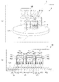
- FIGS. 1A and 1B are diagrams schematically showing the main structure of the SiC single crystal growth apparatus of the first embodiment according to the present invention, FIG. It is shown in a see-through state, and FIG. 1(b) is a sectional view taken along a virtual plane P1 of FIG. 1(a).
- 2A and 2B are diagrams schematically showing the flow of heat when the heating vessel constituting the SiC single crystal growth apparatus of the first embodiment is heated by the heating means.
- FIG. 4 is a cross-sectional view schematically showing the main structure in a mode having a soaking plate in the first heating part of the SiC single crystal growth apparatus.
- 5A and 5B are schematic diagrams showing the main structure of the SiC single crystal growth apparatus of the second embodiment according to the present invention, FIG. 5(b) is a cross-sectional view taken along the imaginary plane P2 of FIG. 5(a).
- 6A and 6B are schematic diagrams showing the structure of the SiC single crystal growth apparatus of the third embodiment according to the present invention, FIG. 6A being a perspective view and FIG. It is a sectional view in plane P3.
- FIG. 6A being a perspective view and FIG. It is a sectional view in plane P3.
- FIG. 7 is a diagram schematically showing the flow of heat when the heating vessel constituting the SiC single crystal growth apparatus of the second and third embodiments is heated by heating means.
- ) shows the case of the SiC single crystal growth apparatus of the second embodiment
- FIG. 7B shows the case of the SiC single crystal growth apparatus of the third embodiment.
- FIG. 8 schematically shows simulation results of the temperature distribution of the SiC seed crystal placed in the heating container of the SiC single crystal growth apparatus when the C/D ratio is varied.
- (a) is the simulation result when the relationship C/D ⁇ 2 is satisfied
- FIG. 9 shows simulation results of the temperature distribution of the surface of the solid raw material contained in the heating container of the SiC single crystal growth apparatus and the SiC seed crystal arranged in the heating container when the C/D ratio is changed.
- FIG. 10 shows the temperature distribution of the surface of the solid raw material accommodated in the heating vessel of the SiC single crystal growth apparatus and the SiC seed crystal arranged in the heating vessel when the B/A ratio and C/D ratio are varied.
- FIG. 11 shows the heating of the SiC single crystal growth apparatus when changing the magnification of the thermal conductivity in the direction along the first heating surface with respect to the thermal conductivity in the direction perpendicular to the first heating surface.
- Fig. 11(a) schematically shows a simulation result of the temperature distribution on the surface of a solid raw material contained in a container.
- FIG. 11(c) is the simulation result when the magnification is 4 times
- FIG. 11(d) is the simulation result when the magnification is 2 times.
- SiC single crystal growth apparatuses according to some embodiments of the present invention will be described below.
- FIGS. 1A and 1B are diagrams schematically showing the main structure of the SiC single crystal growth apparatus of the first embodiment according to the present invention, FIG. It is shown in a see-through state, and FIG. 1(b) is a cross-sectional view taken along a virtual plane P1 of FIG. 1(a).
- FIG. 2 is a diagram schematically showing the flow of heat when the heating vessel constituting the SiC single crystal growth apparatus of the first embodiment is heated by the heating means.
- FIG. 2B shows the case of not satisfying the relationship of B/A ⁇ 2.
- FIG. 3 shows the simulation results of the temperature distribution of the SiC single crystal growth apparatus when the B/A ratio is changed.
- a SiC single crystal growth apparatus 1 has a cylindrical side peripheral portion 14, and a portion of an internal space S defined by the side peripheral portion 14 has a , and a seed crystal 2 of SiC on the side of the internal space S of the raw material storage portion 12 in which the solid raw material M(s) is not stored. and a heating means 3 for heating the heating vessel 10, wherein the heating means 3 is on the outer surface side of the heating vessel 10 and the seed crystal mounting part 16 and It has at least a first heating section 31 having a first heating surface 31a facing the main surface portion of the raw material storage section 12 facing the raw material storage section 12 in a positional relationship covering the entire outer surface of the main surface portion.
- the relationship B/A ⁇ 2 is satisfied.
- the first heating unit 31 is arranged with respect to the main surface portion such as the bottom surface portion 15 of the raw material container 12 so as to cover the entire outer surface of the main surface portion.
- the area B of the first heating surface 31a of the portion 31 twice or more the sliced area A of the internal space S, the entire main surface portion of the raw material containing portion 12 is heated by the first heating portion 31.
- the first heating surface 31a of the first heating unit 31 extends not only to the portion facing the raw material storage unit 12 but also to the outside of the raw material storage unit 12, and the first heating is performed from the vicinity of the outer periphery of the first heating unit 31. It is considered that the heat H is less likely to leak to the outside of the portion 31 .
- the SiC single crystal growth apparatus 1 uniformly heats the solid raw material M(s) contained in the raw material container 12 of the heating vessel 10 (for example, a plurality of crucibles 11) to produce a gaseous raw material derived from the solid raw material. can be sublimated. Furthermore, by uniformly heating and sublimating the solid raw material M(s), the uniformity of the growth rate of the SiC single crystal for each seed crystal when growing the SiC single crystal, and the inside of one seed crystal Since the uniformity of the growth rate is improved, waste of raw materials can be reduced when cutting out a substrate or the like from the obtained SiC single crystal.
- the SiC single crystal growth apparatus 1 includes at least a heating vessel 10 and heating means 3 .
- the heating container 10 is configured by one or more crucibles 11 .
- the heating container 10 is composed of a single crucible 11 .
- the crucibles 11 constituting the heating container 10 each have a cylindrical side peripheral portion 14, and a solid raw material M(s) made of SiC is partially contained in the internal space S defined by the side peripheral portion 14. It has a raw material storage part 12 to be stored.
- the raw material storage portion 12 is configured by, for example, a bottom portion 13 and a cylindrical side peripheral portion 14 connected to the bottom portion 13 .
- the solid raw material M(s) contained in the raw material containing portion 12 is contained in a portion in the height direction Y of the internal space S of the crucible 11 defined by the side peripheral portion 14 . Moreover, it is preferable that the solid raw material M(s) is accommodated in the main surface portion of the crucible 11 that is arranged to face the first heating surface 31a of the first heating unit 31, which will be described later.
- the main surface portion of the crucible 11 is, for example, the bottom surface portion 15 at the bottom portion 13 of the crucible 11 when the crucible 11 is arranged above the first heating section 31 as shown in FIG.
- the main surface portion is the upper surface portion of the lid portion of the crucible 11, and the solid source material M(s) is placed on the opposite surface of the upper surface portion. housed (not shown).
- the crucible 11 constituting the heating vessel 10 has a seed crystal attachment portion in which the SiC seed crystal 2 is arranged on the side of the internal space S in which the solid source material M(s) is not stored in the source material storage portion 12 . 16.
- the solid source material M(s) and the seed crystal 2 are placed in the same space, the internal space S, so that when the heating vessel 10 is heated by the heating means 3 described later, the solid source material M(s) and the seed crystal 2 are stored in the source material storage section 12 .
- the gaseous raw material M(g) generated by sublimation of the solid raw material M(s) thus obtained can reach the seed crystal 2, and as a result, a SiC single crystal can be grown.
- the size of the SiC seed crystal 2 attached by the seed crystal attachment portion 16 is not particularly limited.
- the SiC single crystal growth apparatus 1 of the present embodiment uses a crystal having a large growth surface area as the seed crystal 2, for example, a crystal having a diameter of more than 2 inches (50.8 mm) or a crystal having a diameter of 6 inches (152.4 mm) or more. Even when a crystal is used to grow a larger SiC single crystal, since the solid source material M(s) facing the seed crystal 2 can be uniformly sublimated, the SiC single crystal can be grown efficiently. It is possible.
- the means for attaching the seed crystal 2 to the crucible 11 with the seed crystal attachment portion 16 is not particularly limited, but from the viewpoint of facing the lower surface of the seed crystal 2 to the solid raw material M(s), for example, the seed crystal attachment portion 16 Alternatively, a pedestal projecting from the inner wall of the crucible 11 may be provided to hold the outer periphery of the seed crystal 2 .
- the crucible 11 constituting the heating container 10 may include a lid portion 17 in order to increase the vapor pressure inside the crucible 11 of the gaseous raw material M(g) generated by sublimation of the solid raw material M(s). preferable.
- the material of the crucible 11 is heated to a high temperature when sublimating the solid raw material M(s) to grow the SiC single crystal, so it is desirable that the crucible 11 be made of a material that can withstand high temperatures.
- Materials that can withstand such high temperatures include graphite, graphite coated with tantalum, and tantalum carbide.
- the heating means 3 is arranged on the outer surface side of the heating container 10 and heats the heating container 10 .
- the solid source material M(s) contained in the heating vessel 10 can be heated, thereby sublimating the solid source material M(s).
- the gaseous raw material M(g) generated by sublimation reaches the seed crystal 2 through the internal space S defined by the side peripheral portion 14 of the crucible 11, and is cooled by the seed crystal 2 to produce a SiC single crystal. can grow.
- the SiC single crystal growth apparatus 1 of this embodiment has at least a first heating section 31 as the heating means 3 .
- the first heating unit 31 is arranged to face the main surface portion of the raw material accommodating portion 12 facing the seed crystal mounting portion 16 in the heating vessel 10 in a positional relationship that covers the entire outer surface of this main surface portion. 1 heating surface 31a. As a result, the entire main surface portion of the raw material accommodating portion 12 in which the first heating portion 31 is arranged can be heated by the first heating portion 31 .
- the bottom portion 15 of the crucible 11 can be used as the main surface portion of the raw material container 12 .
- the upper surface portion of the crucible 11 can be used as the main surface portion of the raw material container 12 (not shown).
- the first heating part 31 constituting the heating means 3 and the crucible 11 constituting the heating container 10 are B /A ⁇ 2.
- the first heating section 31 is arranged in a positional relationship covering the entire outer surface of the main surface portion such as the bottom surface portion 15 of the raw material containing portion 12, and the first heating portion
- the entire main surface portion of the raw material container 12 is heated by the first heating unit 31 .
- the first heating surface 31 a of the first heating unit 31 spreads not only to the portion facing the raw material storage unit 12 but also to the outside of the raw material storage unit 12 .
- the first heating surface 31 a of the first heating unit 31 is similar to the raw material storage unit 12 when viewed in a cross section perpendicular to the first heating surface 31 a. (bottom portion 15 in FIG. 2(a)) toward at least one side along the surface direction of the main surface portion. More preferably, the first heating surface 31a extends from the main surface portion of the raw material container 12 toward both sides along the surface direction of the main surface portion.
- the heating means 3 by providing the first heating portion 31 in which the first heating surface 31a extends from the main surface portion of the raw material accommodating portion 12, as shown in FIG.
- the heat H emitted from the first heating surface 31a of the heating unit 31 is evenly applied to the main surface portion of the raw material container 12 (Fig. 2) by the first heating surface 31a extending from the main surface portion of the raw material container 12. Since the heat is transmitted to the bottom portion 15) of (a), the solid raw material M(s) accommodated inside the raw material container 12 can be heated uniformly.
- the reason why the main surface portion of the raw material accommodating portion 12 can be uniformly heated in this way is that the heat H is less likely to leak from the vicinity of the outer periphery of the first heating portion 31 to the outside of the first heating portion 31 . is mentioned.
- the first heating surface 31a does not extend from the main surface portion of the raw material container 12 as shown in FIG.
- the heat H leaks from the vicinity of the outer periphery of the first heating unit 31 to the outside of the first heating unit 31, and this makes it difficult to uniformly heat the main surface portion of the raw material storage unit 12. .
- the ratio of the area B of the first heating surface 31a of the first heating unit 31 to the sliced area A of the internal space S is two or more times from the viewpoint of uniformly sublimating the solid raw material M(s).
- the upper limit of the ratio of the area B of the first heating surface 31a of the first heating unit 31 to the sliced area A of the internal space S is not particularly limited. It may be below.
- the difference in surface temperature of the solid raw material M(s) is preferably 20° C. or less, more preferably 10° C. or less.
- the ratio of the area B of the first heating surface 31a of the first heating unit 31 to the sliced area A of the internal space S is smaller than 2 times, for example, when the ratio of B to A is 1,
- the temperature of the solid raw material M(s) contained in the raw material container 12 of the crucible 11 is partially below 2002° C., and the solid raw material M(s) is heated.
- the uniformity at the time of Note even when the ratio of the area B of the first heating surface 31a of the first heating unit 31 to the sliced area A of the internal space S is large, as shown in FIG. Although it is considered that the solid raw material M(s) stored in the storage unit 12 is uniformly heated, the solid raw material M(s) is heated to 2340° C. or higher, which may result in thermal waste.
- the type of the heat source 33 of the first heating unit 31 that constitutes the heating means 3 is not particularly limited, and known means such as resistance heating and induction heating can be used. Among them, from the viewpoint of facilitating control of the amount of heat generated by the heat source 33, it is preferably configured by a resistance heating means, and more preferably configured by a resistance heating means having a three-phase alternating current feeding mechanism. Moreover, the heat source 33 of the first heating unit 31 is preferably provided on the back side of the first heating surface 31a from the viewpoint of improving the heat balance in the first heating unit 31 . Furthermore, the first heating surface 31a of the first heating unit 31 may be the surface of the heat source 33 constituting the first heating unit 31, as in the SiC single crystal growth apparatus 1 shown in FIG. 4, a plate-like member provided between the heat source 33 and the bottom surface of the heating container 10 and substantially parallel to the bottom surface of the heating container 10, and It may be the surface of a heat equalizing plate 34 that constitutes a part of the heating unit 31 .
- the first heating surfaces 31a of the first heating portions 31, 31A are preferably made of an anisotropic material having at least anisotropy in thermal conductivity.
- the heat source 33 and the heat equalizing plate 34 having the first heating surface 31a have a thermal conductivity in the direction along the first heating surface 31a and a thermal conductivity in the direction perpendicular to the first heating surface 31a. higher than the rate is preferred.
- the heat conduction along the thickness direction of the heat source 33 and the heat equalizing plate 34 is moderated, and the heat conduction along the first heating surface 31a is promoted. Therefore, heat can be evenly transferred to the entire first heating surface 31 a , so that heat can be evenly emitted from the first heating surface 31 a toward the crucible 11 .
- the solid raw material M(s) can be heated more uniformly.
- heat generation along the first heating surface 31a may occur due to the shape of the heat source itself, the presence of electrodes that supply electricity to the heat source, the presence of support portions that support the heat source, and the like. Possibility of becoming heterogeneous is conceivable. Even in such a case, by forming the first heating surface 31a with an anisotropic material having an anisotropic thermal conductivity as described above, the heat from the first heating surface 31a to the crucible 11 can be reduced. Can be directed to evenly distribute heat.
- a carbon material containing carbon fiber is preferably used as such an anisotropic material.
- carbon materials containing carbon fibers include C/C composite materials (Carbon Fiber Reinforced Carbon Composite).
- C/C composite materials Carbon Fiber Reinforced Carbon Composite
- the thermal conductivity of the first heating surface 31a can be made anisotropic by the orientation of the carbon fibers, and the mechanical strength such as the tensile strength and bending strength of the anisotropic material can be improved. can.
- the mechanical strength such as the tensile strength and bending strength of the anisotropic material can be improved. can.
- the ratio of the thermal conductivity in the direction along the first heating surface 31a to the thermal conductivity in the direction perpendicular to the first heating surface 31a in the anisotropic material is preferably 2 times or more. , more preferably four times or more.
- the upper limit of the ratio of the thermal conductivity in the direction along the first heating surface 31a to the thermal conductivity in the direction perpendicular to the first heating surface 31a is not particularly limited, From the viewpoint of facilitating transfer of heat from the heat source to the crucible 11, the upper limit may be 10 times.
- Such an anisotropic material can be formed by arranging carbon fibers along the first heating surface 31a when forming a material such as graphite that can withstand high temperatures.
- the carbon fiber may be thin carbon felt or carbon paper arranged along the surface that becomes the first heating surface 31a.
- the thickness of the anisotropic material is preferably 3 mm or more from the viewpoint of increasing the mechanical strength of the first heating parts 31, 31A and facilitating insertion and removal from the SiC single crystal growth apparatuses 1, 1A.
- the thickness of the anisotropic material is preferably 30 mm or less from the viewpoint of not blocking heat from the heat source.
- FIGSecond embodiment> 5A and 5B are schematic diagrams showing the main structure of the SiC single crystal growth apparatus of the second embodiment according to the present invention
- FIG. 5(b) is a cross-sectional view taken along the imaginary plane P2 of FIG. 5(a).
- the same reference numerals are given to the same components as in the first embodiment, and the description thereof is omitted or simplified, and mainly the differences are described.
- the heating container 10 has a single crucible 11, but the configuration is not limited to this.
- the heating container 10B may be composed of a plurality of crucibles 11a to 11g.
- a plurality of SiC single crystals can be grown simultaneously in one SiC single crystal growth apparatus 1B, and the weight of the crucible can be reduced because the crucible is individualized compared to the case of using a large crucible. can be easily handled.
- the heating container 10B by forming the heating container 10B with a plurality of crucibles 11a to 11g, uniform sublimation of the solid raw material M(s) can be further promoted.
- the heating means 3 is arranged so that all the crucibles 11a to 11g constituting the heating vessel 10B are positioned to cover the entire outer surface of the main surface portion of the raw material container 12, and the first heating portion 31 is preferred.
- the first heating unit 31 constituting the heating means 3 and the crucibles 11a to 11g constituting the heating container 10B have A and the area of the first heating surface 31a. is B, the relationship B/A ⁇ 2 is satisfied.
- the SiC single crystal growth apparatus 1B preferably includes a plurality of crucibles 11a to 11g forming the heating vessel 10B and a chamber 5 housing the heating vessel 10B.
- the external atmosphere of the heating container 10B can be easily adjusted, and the crucibles 11a to 11g can be prevented from being damaged by heating.
- the plurality of crucibles 11a to 11c are filled with gas derived from the solid raw material generated by sublimating the solid raw material M(s) accommodated in the respective raw material accommodating portions 12a to 12c. It is preferable to have gaps 18a to 18c through which part of the raw material M(g) is discharged into the chamber 5 from the raw material containing portion. As a result, impurities are discharged from the crucibles 11a-11c through the gaps 18a-18c.
- the gaseous source material M(g) is released into the chamber 5 through the gaps 18a to 18c of the plurality of crucibles 11a to 11c, respectively, and fills the chamber 5, thereby causing the vapor of the gaseous source material M(g) in the chamber 5. Since the pressure is shared among the plurality of crucibles 11a to 11c, the vapor pressure of the gaseous raw material M(g) in the plurality of crucibles 11a to 11c becomes substantially uniform (dumping effect). Therefore, it is possible to suppress temporal change in the composition of the gaseous raw material M(g) due to impurities in the crucibles 11a to 11c, and to further promote uniform growth of a plurality of SiC single crystals.
- the gaps 18a to 18c can be formed by providing gaps in the fitting portions when assembling the crucibles 11a to 11c.
- the fitting portions for assembling the crucibles 11a to 11c include, for example, the fitting portions between the raw material storage portions 12a to 12c and the seed crystal mounting portions 16a to 16c, and the fitting portions between the seed crystal mounting portions 16a to 16c and the lid portions 17a to 17c.
- a fitting part can be mentioned.
- the number of crucibles constituting the heating container 10B provided in the SiC single crystal growth apparatus 1B is not particularly limited.
- the number is preferably 7 or more.
- the number of crucibles included in SiC single crystal growth apparatus 1B may be 19 or less.
- the intervals between the plurality of crucibles 11a to 11g constituting the heating container 10B are not particularly limited, but from the viewpoint of enhancing the balance of vapor pressure between the crucibles 11a to 11g, the first heating surface 31a of the crucibles 11a to 11g It may be half or less of the size along the line.
- FIG. 6A and 6B are schematic diagrams showing the structure of the SiC single crystal growth apparatus of the third embodiment according to the present invention, FIG. 6A being a perspective view and FIG. It is a sectional view in plane P3.
- FIG. 7 is a diagram schematically showing the flow of heat when the heating vessel constituting the SiC single crystal growth apparatus of the second and third embodiments is heated by the heating means.
- 7A shows the case of the SiC single crystal growth apparatus of the second embodiment
- FIG. 7B shows the case of the SiC single crystal growth apparatus of the third embodiment.
- the same reference numerals are given to the same components as those of the first embodiment or the second embodiment, and the description thereof will be omitted or simplified, and mainly the differences will be described.
- the heating means 3 has the first heating portion 31 covering the entire outer surface of the main surface portion of the raw material containing portion 12. but not limited to this.
- the side peripheral portions 14a to 14a to 14c of the raw material storage sections 12a to 12c are used as the heating means 3C.
- a second heating unit 32 having a second heating surface 32a may be arranged to face 14c in a positional relationship covering the entire outer surfaces of the side peripheral portions 14a to 14c.
- first heating unit 31 and the second heating unit 32 that constitute the heating means 3C are such that when the heating energy by the first heating unit 31 is C and the heating energy by the second heating unit 32 is D, C is Greater than D is preferred.
- the raw material storage units of the crucibles 11a to 11g (raw material storage unit 12a in FIG. 6B) 12c) are uniformly heated, and the crystal growth surfaces of the seed crystals 2a to 2c are arranged in parallel to the first heating surface 31a, so that the crucible 11a Since the surface temperatures of the seed crystals 2a to 2c arranged at 11g are also uniform, the uniformity of the growth rate of the SiC single crystal can be further improved.
- the heating means 3C in the SiC single crystal growth apparatus 1C includes the first heating unit 31 and the second heating unit 32, and the heating energy C by the first heating unit 31 is replaced by the heating energy D by the second heating unit 32.
- the heat H emitted from the first heating surface 31a of the first heating unit 31 is directed away from the first heating surface 31a (FIG. 7(b) ), and the isothermal lines L1 to L3 are substantially parallel to the first heating surface 31a, so that the surface temperatures of the seed crystals 2a to 2c can be made uniform.
- the second heating portion 32 allows the temperature from near the outer circumference of the first heating portion 31 to the outside of the first heating portion 31 to flow.
- the leakage of the heat H from the inside of the crucibles 11a to 11c becomes more difficult, and the heat H locally lost due to the leakage to the outside of the first heating unit 31 is replenished by the second heating unit 32.
- the energy density in the space S becomes equal.
- the isotherms L1′ to L3′ extend outside the first heating section 31.
- the ratio (C/D ratio) of the heating energy C by the first heating unit to the heating energy D by the second heating unit (C/D ratio) is 1.00 from the viewpoint of uniforming the surface temperatures of the seed crystals 2a to 2c. Larger is preferred, and 1.20 or more is more preferred.
- the upper limit of the ratio (C/D ratio) of the heating energy C by the first heating unit to the heating energy D by the second heating unit (C/D ratio) is not particularly limited. From the viewpoint of doing so, it may be less than 3.50, or may be 3.00 or less.
- FIG. 1 As a model of the crucible 11 containing the solid raw material M(s) and the seed crystal 2, it has a cylindrical inner space S with a diameter of 180 mm and a height of 60 mm, and the inner space S is a cylindrical side peripheral portion with an inner diameter of 180 mm. 14, at a height of 70 mm from the bottom of the internal space S, SiC powder (manufactured by Taiheiyo Rundum Co., Ltd., model number: GMF-H), which is a solid raw material M (s) ), a seed crystal mounting portion 16 was provided at a height of 60 mm from the bottom of the internal space S, and a seed crystal 2 with a diameter of 150 mm was arranged.
- SiC powder manufactured by Taiheiyo Rundum Co., Ltd., model number: GMF-H
- the first heating unit 31 a plate-shaped soaking plate 34 provided substantially parallel to the bottom surface of the crucible 11 and having the above-described first heating surface 31a, and the first heating surface 31a of the soaking plate 34 and a heat source 33 provided on the back side of the heat source 33 and configured by resistance heating means having a three-phase alternating current power feeding mechanism.
- the heat equalizing plate 34 is made of a C/C composite material which is an anisotropic material, and the thermal conductivity of this anisotropic material in the direction perpendicular to the first heating surface 31a is 10 W. /mK, and the thermal conductivity in the direction along the first heating surface 31a was 40 W/mK. Therefore, the thermal conductivity in the direction along the first heating surface 31a was four times the thermal conductivity in the direction perpendicular to the first heating surface 31a.
- a cylindrical second heating unit 32 having an inner diameter of 1200 mm and a height of 230 mm is arranged outside the first heating unit 31 so as to be concentric with the first heating unit 31 in plan view.
- An apparatus model was constructed for simulating the surface temperature of the solid source material M(s) in the crystal growth apparatus. Then, the surface temperature of the solid raw material M(s) when heated for 300 minutes with the heating energy C by the first heating unit being 80 kW and the heating energy D by the second heating unit being 40 kW was measured by FEMTET manufactured by Murata Software Co., Ltd. (trade name) was used for the simulation. At this time, the ratio (C/D ratio) of the heating energy C by the first heating unit to the heating energy D by the second heating unit was 2.00.
- the surface temperature difference in the solid raw material M(s) was 10°C or less.
- the simulation result of the temperature distribution of the SiC seed crystal arranged in the crucible 11 of the SiC single crystal growth apparatus 1D the temperature difference in the surface temperature of the SiC seed crystal 2 is also 10 °C or less.
- FIG. 8(b) shows a simulation result of the temperature distribution of the SiC seed crystal placed in the crucible 11 of the SiC single crystal growth apparatus 1E, including the surface of the solid source material M(s).
- the surface temperature of the seed crystal 2 had a temperature difference in the range of more than 30°C and 40°C or less.
- the first heating unit 31 is configured such that the heat equalizing plate 34 and the heat source 33 are arranged as in the first example of the present invention.
- the heat equalizing plate 34 is made of a C/C composite material which is an anisotropic material, and the thermal conductivity of this anisotropic material in the direction perpendicular to the first heating surface 31a is 10 W. /mK, and the thermal conductivity in the direction along the first heating surface 31a was 40 W/mK. Therefore, the thermal conductivity in the direction along the first heating surface 31a was four times the thermal conductivity in the direction perpendicular to the first heating surface 31a.
- a cylindrical second heating unit 32 having an inner diameter of 750 mm and a height of 230 mm is arranged outside the first heating unit 31 so as to be concentric with the first heating unit 31 in plan view.
- An apparatus model was constructed for simulating the surface temperature of the solid source material M(s) in the crystal growth apparatus. Then, the surface temperature of the solid raw material M(s) when heated for 300 minutes with the heating energy C by the first heating unit being 40 kW and the heating energy D by the second heating unit being 20 kW was measured by FEMTET manufactured by Murata Software Co., Ltd. (trade name) was used for the simulation. At this time, the ratio (C/D ratio) of the heating energy C by the first heating unit to the heating energy D by the second heating unit was 2.00.
- FIG. 9A shows the simulation result (left side) of the temperature distribution on the surface of the solid source material M(s) accommodated in the crucible 11 of the SiC single crystal growth apparatus 1F, and the SiC seed crystal 2 placed in the crucible 11. shows the simulation results (right side) for the temperature distribution of .
- the temperature difference in the surface temperature of the solid source material M(s) and the temperature difference in the surface temperature of the seed crystal 2 were both 10° C. or less.
- FIG. 9B shows the simulation result (left side) of the temperature distribution on the surface of the solid source material M(s) accommodated in the crucible 11 of the SiC single crystal growth apparatus 1G, and the SiC seed crystal 2 placed in the crucible 11. shows the simulation results (right side) for the temperature distribution of .
- the temperature difference in the surface temperature of the solid source material M(s) and the temperature difference in the surface temperature of the seed crystal 2 were both 10° C. or less.
- FIG. 10(a) shows the simulation result (left side) of the temperature distribution on the surface of the solid source material M(s) accommodated in the crucible 11 of the SiC single crystal growth apparatus 1H, and the SiC seed crystal 2 arranged in the crucible 11. shows the simulation results (right side) for the temperature distribution of .
- the surface temperature difference in the solid raw material M(s) was 10° C. or less.
- the surface temperature of the SiC seed crystal 2 had a temperature difference in the range of more than 20°C and 30°C or less.
- a cylindrical second heating unit 32 having an inner diameter of 750 mm and a height of 230 mm is arranged outside the first heating unit 31 so as to be concentric with the first heating unit 31 in plan view.
- An apparatus model was constructed for simulating the surface temperature of the solid source material M(s) in the crystal growth apparatus. Then, the surface temperature of the solid raw material M(s) when heated for 300 minutes with the heating energy C by the first heating unit being 25 kW and the heating energy D by the second heating unit being 20 kW was measured by FEMTET manufactured by Murata Software Co., Ltd. (trade name) was used for the simulation. At this time, the ratio (C/D ratio) of the heating energy C by the first heating unit to the heating energy D by the second heating unit was 1.25.
- FIG. 10(b) shows the simulation result (left side) of the temperature distribution on the surface of the solid source material M(s) accommodated in the crucible 11 of the SiC single crystal growth apparatus 1I, and the SiC seed crystal 2 arranged in the crucible 11. shows the simulation results (right side) for the temperature distribution of .
- the surface temperature of the solid raw material M(s) had a temperature difference in the range of more than 20°C and 30°C or less.
- the difference in surface temperature of seed crystal 2 was 10° C. or less.
- the first heating unit 31 is configured such that the heat equalizing plate 34 and the heat source 33 are arranged as in the first example of the present invention.
- the heat equalizing plate 34 is made of a C/C composite material which is an anisotropic material, and the thermal conductivity of this anisotropic material in the direction perpendicular to the first heating surface 31a is 1 W. /mK, and the thermal conductivity in the direction along the first heating surface 31a was 10 W/mK. Therefore, the thermal conductivity in the direction along the first heating surface 31a was 10 times the thermal conductivity in the direction perpendicular to the first heating surface 31a.
- a cylindrical second heating unit 32 having an inner diameter of 750 mm and a height of 230 mm is arranged outside the first heating unit 31 so as to be concentric with the first heating unit 31 in plan view.
- An apparatus model was constructed for simulating the surface temperature of the solid source material M(s) in the crystal growth apparatus. Then, the surface temperature of the solid raw material M(s) when heated for 300 minutes with the heating energy C by the first heating unit being 25 kW and the heating energy D by the second heating unit being 20 kW was measured by FEMTET manufactured by Murata Software Co., Ltd. (trade name) was used for the simulation. At this time, the ratio (C/D ratio) of the heating energy C by the first heating unit to the heating energy D by the second heating unit was 1.25.
- FIG. 11(a) shows a simulation result of the temperature distribution on the surface of the solid raw material M(s) accommodated in the crucible 11 of the SiC single crystal growth apparatus 1J.
- the difference in surface temperature of the solid raw material M(s) was 10° C. or less.
- FIG. 11(b) shows the simulation result of the temperature distribution on the surface of the solid raw material M(s) accommodated in the crucible 11 of the SiC single crystal growth apparatus 1K.
- the difference in surface temperature of the solid raw material M(s) was 10° C. or less.
- FIG. 11(c) shows the simulation result of the temperature distribution on the surface of the solid raw material M(s) accommodated in the crucible 11 of the SiC single crystal growth apparatus 1L.
- the temperature difference in the surface temperature of the solid raw material M(s) was 20° C. or less.
- the thermal conductivity in the direction perpendicular to the first heating surface 31a of the C/C composite material is set to 20 W/mK.
- the surface temperature of the solid raw material M(s) was simulated when the thermal conductivity in the direction along the first heating surface 31a was 40 W/mK.
- the thermal conductivity in the direction along the first heating surface 31a was twice the thermal conductivity in the direction perpendicular to the first heating surface 31a.
- FIG. 11(d) shows the simulation result of the temperature distribution on the surface of the solid raw material M(s) accommodated in the crucible 11 of the SiC single crystal growth apparatus 1M.
- the temperature difference in the surface temperature of the solid raw material M(s) was 20° C. or less.
- the ratio (B/A) of the area B of the first heating surface to the sliced area A of the internal space is 2 or more, and It was found that the temperature difference in the surface temperature of the solid raw material M(s) was small and that the solid raw material M(s) was heated almost uniformly.
- the SiC single crystal growth apparatuses of Examples 1 to 9 of the present invention can uniformly heat the solid raw material to sublimate the gaseous raw material derived from the solid raw material, thereby making it possible to grow the SiC single crystal. It was possible to reduce the waste of
- the ratio (B/A) of the area B of the first heating surface to the sliced area A of the internal space was less than 2. Therefore, in the SiC single crystal growth apparatus of Comparative Example 1, variations in the surface temperature of the solid source material M(s) were observed.
- the ratio (C /D ratio) exceeds 1.00, the surface temperature of the seed crystal 2 is also substantially uniform, unlike Inventive Examples 2 and 5 in which the C/D ratio is below 1.00. .
- the thermal conductivity in the direction perpendicular to the first heating surface 31a is as follows: By configuring the first heating surface 31a with an anisotropic material having a thermal conductivity factor of 4 or more in the longitudinal direction, the first heating surface 31a is formed from a material with a thermal conductivity factor of less than 4. It was found that the surface temperature difference in the solid raw material M(s) can be made smaller than in Examples 8 and 9 of the present invention.
Landscapes
- Chemical & Material Sciences (AREA)
- Engineering & Computer Science (AREA)
- Crystallography & Structural Chemistry (AREA)
- Materials Engineering (AREA)
- Metallurgy (AREA)
- Organic Chemistry (AREA)
- Inorganic Chemistry (AREA)
- Crystals, And After-Treatments Of Crystals (AREA)
- Physical Vapour Deposition (AREA)
Abstract
Description
(1)筒状の側周部分を有し、前記側周部分で区画形成された内部空間の一部分に、SiCからなる固体原料が収容される原料収容部、および、前記原料収容部の、前記固体原料が収容されていない前記内部空間の側に、SiCの種結晶が配置される種結晶取付部を有する加熱容器と、前記加熱容器を加熱する加熱手段とを備え、前記加熱手段が、前記加熱容器の外面側であってかつ前記種結晶取付部と対向する前記原料収容部の主面部分に対し、該主面部分の外面全体を覆う位置関係で対向配置される第1加熱面を有する第1加熱部を少なくとも有し、前記内部空間の輪切り面積をA、前記第1加熱面の面積をBとしたときに、B/A≧2の関係を満たす、SiC単結晶成長装置。
(2)前記加熱手段は、前記加熱容器の外面側であってかつ前記原料収容部の前記側周部分に対し、該側周部分の外面全体を覆う位置関係で対向配置される第2加熱面を有する第2加熱部をさらに備え、前記第1加熱部による加熱エネルギーをC、前記第2加熱部による加熱エネルギーをDとしたときに、CはDよりも大きい、上記(1)に記載のSiC単結晶成長装置。
(3)前記第1加熱部による加熱エネルギーCと、前記第2加熱部による加熱エネルギーDは、C/D≧1.20の関係を満たす、上記(2)に記載のSiC単結晶成長装置。
(4)前記加熱容器は、複数の坩堝で構成され、前記SiC単結晶成長装置は、前記複数の坩堝および前記加熱手段を収容するチャンバをさらに備え、前記複数の坩堝は、それぞれの前記原料収容部に収容された前記固体原料を昇華させて生成した固体原料由来の気体原料の一部を、前記原料収容部から前記チャンバ内に放出する隙間部を有する、上記(1)、(2)、または(3)に記載のSiC単結晶成長装置。
(5)前記加熱手段の第1加熱面は、少なくとも熱伝導率に異方性を有する異方性材料で構成される、上記(1)から(4)のいずれか1項に記載のSiC単結晶成長装置。
(6)前記異方性材料は、カーボンファイバーを含んだ炭素材料である、上記(5)に記載のSiC単結晶成長装置。
(7)前記加熱手段は、前記第1加熱面の熱源を前記第1加熱面の裏側に備え、前記熱源は、3相交流の給電機構を有する抵抗加熱手段によって構成される、上記(1)から(6)のいずれか1項に記載のSiC単結晶成長装置。
図1は、本発明に従う第1実施形態のSiC単結晶成長装置の要部構造を模式的に示した図であって、図1(a)が斜視図であって、坩堝の内部空間Sを透視した状態で示し、また、図1(b)が図1(a)の仮想平面P1における断面図である。また、図2は、第1実施形態のSiC単結晶成長装置を構成する加熱容器を加熱手段で加熱したときの熱の流れを模式的に示した図であって、図2(a)がB/A≧2の関係を満たす場合、図2(b)がB/A≧2の関係を満たさない場合を示す。また、図3は、B/A比を変化させたときの、SiC単結晶成長装置の温度分布についてのシミュレーション結果であって、図3(a)がB/A=2の場合のシミュレーション結果、図3(b)がB/A=1の場合のシミュレーション結果、図3(c)がB/A=3の場合のシミュレーション結果である。
このうち、加熱容器10は、単数または複数の坩堝11によって構成される。特に、本実施形態では、加熱容器10は、単数の坩堝11によって構成される。
加熱手段3は、加熱容器10の外面側に配置され、加熱容器10を加熱するものである。加熱容器10を加熱する加熱手段3を備えることで、加熱容器10に収容された固体原料M(s)を加熱し、それにより固体原料M(s)を昇華させることができる。昇華により生成する気体原料M(g)が、坩堝11の側周部分14で区画形成された内部空間Sを通って種結晶2に到達し、種結晶2によって冷却されることで、SiC単結晶を成長させることができる。
これにより、熱源33や均熱板34の厚さ方向に沿った熱の伝導が緩やかになるとともに、第1加熱面31aに沿った熱の伝導が促進される。そのため、第1加熱面31aの全体に満遍なく熱を伝えることができ、それにより第1加熱面31aから坩堝11に向けて、均等に熱を発することができる。その結果、固体原料M(s)をより均一に加熱することができる。
他方で、異方性材料の厚さは、熱源からの熱を遮断しない観点から、30mm以下であることが好ましい。
図5は、本発明に従う第2実施形態のSiC単結晶成長装置の要部構造を示した概略図であって、図5(a)が斜視図であって、坩堝の内部空間Sを透視した状態で示し、また、図5(b)が図5(a)の仮想平面P2における断面図である。なお、以下の説明において、上記第1実施形態と同一の構成要素には同一の符号を付してその説明を省略または簡略にし、主に相違点について説明する。
図6は、本発明に従う第3実施形態のSiC単結晶成長装置の構造を示した概略図であって、図6(a)が斜視図、図6(b)が図6(a)の仮想平面P3における断面図である。また、図7は、第2実施形態および第3実施形態のSiC単結晶成長装置を構成する加熱容器を加熱手段で加熱したときの熱の流れを模式的に示した図であって、図7(a)が第2実施形態のSiC単結晶成長装置の場合、図7(b)が第3実施形態のSiC単結晶成長装置の場合を示す。なお、以下の説明において、上記第1実施形態または第2実施形態と同一の構成要素には同一の符号を付してその説明を省略または簡略にし、主に相違点について説明する。
固体原料M(s)と種結晶2が収容された坩堝11のモデルとして、直径180mm、高さ60mmの円柱状の内部空間Sを有し、内部空間Sが内径180mmの円筒状の側周部分14によって形成されている原料収容部12を有する坩堝11に、内部空間Sの底から70mmの高さで、固体原料M(s)であるSiC粉末(太平洋ランダム株式会社製、型番:GMF-H)を収容し、さらに、内部空間Sの底から60mmの高さ位置に種結晶取付部16を設けて、直径150mmの種結晶2を配置したモデルを構成した。
本発明例1と同じ装置モデルについて、第1加熱部による加熱エネルギーCを60kW、第2加熱部による加熱エネルギーDを60kWとして300分間加熱したときの、固体原料M(s)の表面温度をシミュレーションした。このとき、第1加熱部による加熱エネルギーCの、第2加熱部による加熱エネルギーDに対する比(C/D比)は、1.00であった。
本発明例1と同じ坩堝11のモデルを用い、図9(a)に記載されるような配置で、直径650mmの第1加熱面31aを有する平板状の第1加熱部31に、等間隔に7個載置した。このとき、それぞれの坩堝11における内部空間Sの輪切り面積Aは2.54×104mm2、第1加熱面31aの面積Bは3.31×105mm2と計算されるため、B/A比は13.0であった。
本発明例3と同じ装置モデルについて、第1加熱部による加熱エネルギーCを25kW、第2加熱部による加熱エネルギーDを20kWとして300分間加熱したときの、固体原料M(s)の表面温度をシミュレーションした。このとき、第1加熱部による加熱エネルギーCの、第2加熱部による加熱エネルギーDに対する比(C/D比)は、1.25であった。
本発明例3と同じ装置モデルについて、第1加熱部による加熱エネルギーCを20kW、第2加熱部による加熱エネルギーDを40kWとして300分間加熱したときの、固体原料M(s)の表面温度をシミュレーションした。このとき、第1加熱部による加熱エネルギーCの、第2加熱部による加熱エネルギーDに対する比(C/D比)は、0.50であった。
本発明例1と同じ坩堝11のモデルを用い、図10(b)に記載されるような配置で、直径98.6mmの第1加熱面31aを有する平板状の第1加熱部31に、等間隔に7個載置した。このとき、それぞれの坩堝11における内部空間Sの輪切り面積Aは2.54×104mm2、第1加熱面31aの面積Bは7.63×103mm2と計算されるため、B/A比は0.30であった。
本発明例1と同じ坩堝11のモデルを用い、図11(a)に記載されるような配置で、直径650mmの第1加熱面31aを有する平板状の第1加熱部31に、等間隔に7個載置した。このとき、それぞれの坩堝11における内部空間Sの輪切り面積Aは2.54×104mm2、第1加熱面31aの面積Bは3.31×105mm2と計算されるため、B/A比は13.0であった。
本発明例6と同じ装置モデルについて、均熱板34を構成する異方性材料であるC/Cコンポジット材における、第1加熱面31aに対して垂直な方向についての熱伝導率を10W/mKとし、第1加熱面31aに沿った方向についての熱伝導率を40W/mKとしたときの、固体原料M(s)の表面温度をシミュレーションした。このとき、第1加熱面31aに対して垂直な方向についての熱伝導率に対する、第1加熱面31aに沿った方向についての熱伝導率の倍率は4倍であった。
本発明例6と同じ装置モデルについて、均熱板34を構成する異方性材料であるC/Cコンポジット材における、第1加熱面31aに対して垂直な方向についての熱伝導率を13.3W/mKとし、第1加熱面31aに沿った方向についての熱伝導率を40W/mKとしたときの、固体原料M(s)の表面温度をシミュレーションした。このとき、第1加熱面31aに対して垂直な方向についての熱伝導率に対する、第1加熱面31aに沿った方向についての熱伝導率の倍率は3倍であった。
本発明例6と同じ装置モデルについて、均熱板34を構成する異方性材料であるC/Cコンポジット材における、第1加熱面31aに対して垂直な方向についての熱伝導率を20W/mKとし、第1加熱面31aに沿った方向についての熱伝導率を40W/mKとしたときの、固体原料M(s)の表面温度をシミュレーションした。このとき、第1加熱面31aに対して垂直な方向についての熱伝導率に対する、第1加熱面31aに沿った方向についての熱伝導率の倍率は2倍であった。
10、10B、10C 加熱容器
11、11a~11g 坩堝
12、12a~12c 原料収容部
13 原料収容部の底部
14、14a~14c 原料収容部の側周部分
15 原料収容部の底面部分
16、16a~16c 種結晶取付部
17、17a~17c 蓋部
18a~18c 隙間部
2、2a~2c SiCの種結晶
3 加熱手段
31 第1加熱部
31a 第1加熱面
32 第2加熱部
32a 第2加熱面
33 熱源
34 均熱板
4 断熱材
5 チャンバ
90 比較のためのSiC単結晶成長装置
A 内部空間の輪切り面積
B 第1加熱面の面積
H 加熱手段から発せられる熱の流れ
L1~L3、L1’~L3’ 等温線
S 内部空間
Y 高さ方向
M(s) 固体原料
M(g) 気体原料
Claims (7)
- 筒状の側周部分を有し、前記側周部分で区画形成された内部空間の一部分に、SiCからなる固体原料が収容される原料収容部、および、
前記原料収容部の、前記固体原料が収容されていない前記内部空間の側に、SiCの種結晶が配置される種結晶取付部を有する加熱容器と、
前記加熱容器を加熱する加熱手段とを備え、
前記加熱手段が、前記加熱容器の外面側であってかつ前記種結晶取付部と対向する前記原料収容部の主面部分に対し、該主面部分の外面全体を覆う位置関係で対向配置される第1加熱面を有する第1加熱部を少なくとも有し、
前記内部空間の輪切り面積をA、前記第1加熱面の面積をBとしたときに、B/A≧2の関係を満たす、SiC単結晶成長装置。 - 前記加熱手段は、前記加熱容器の外面側であってかつ前記原料収容部の前記側周部分に対し、該側周部分の外面全体を覆う位置関係で対向配置される第2加熱面を有する第2加熱部をさらに備え、
前記第1加熱部による加熱エネルギーをC、前記第2加熱部による加熱エネルギーをDとしたときに、CはDよりも大きい、請求項1に記載のSiC単結晶成長装置。 - 前記第1加熱部による加熱エネルギーCと、前記第2加熱部による加熱エネルギーDは、C/D≧1.20の関係を満たす、請求項2に記載のSiC単結晶成長装置。
- 前記加熱容器は、複数の坩堝で構成され、
前記SiC単結晶成長装置は、前記複数の坩堝および前記加熱手段を収容するチャンバをさらに備え、
前記複数の坩堝は、それぞれの前記原料収容部に収容された前記固体原料を昇華させて生成した固体原料由来の気体原料の一部を、前記原料収容部から前記チャンバ内に放出する隙間部を有する、請求項1、2または3に記載のSiC単結晶成長装置。 - 前記加熱手段の第1加熱面は、少なくとも熱伝導率に異方性を有する異方性材料で構成される、請求項1から4のいずれか1項に記載のSiC単結晶成長装置。
- 前記異方性材料は、カーボンファイバーを含んだ炭素材料である、請求項5に記載のSiC単結晶成長装置。
- 前記加熱手段は、前記第1加熱面の熱源を前記第1加熱面の裏側に備え、
前記熱源は、3相交流の給電機構を有する抵抗加熱手段によって構成される、請求項1から6のいずれか1項に記載のSiC単結晶成長装置。
Priority Applications (3)
| Application Number | Priority Date | Filing Date | Title |
|---|---|---|---|
| CN202280011111.5A CN116867933A (zh) | 2020-09-28 | 2022-01-17 | SiC单晶生长装置 |
| EP22742531.1A EP4257735A4 (en) | 2020-09-28 | 2022-01-17 | SIC SINGLE CRYSTAL GROWTH APPARATUS |
| US18/262,048 US20240295047A1 (en) | 2020-09-28 | 2022-01-17 | Sic single-crystal growth apparatus |
Applications Claiming Priority (3)
| Application Number | Priority Date | Filing Date | Title |
|---|---|---|---|
| US202063084089P | 2020-09-28 | 2020-09-28 | |
| JP2021007905A JP7643708B2 (ja) | 2020-09-28 | 2021-01-21 | SiC単結晶成長装置 |
| JP2021-007905 | 2021-01-21 |
Publications (1)
| Publication Number | Publication Date |
|---|---|
| WO2022158409A1 true WO2022158409A1 (ja) | 2022-07-28 |
Family
ID=80998189
Family Applications (1)
| Application Number | Title | Priority Date | Filing Date |
|---|---|---|---|
| PCT/JP2022/001309 Ceased WO2022158409A1 (ja) | 2020-09-28 | 2022-01-17 | SiC単結晶成長装置 |
Country Status (6)
| Country | Link |
|---|---|
| US (1) | US20240295047A1 (ja) |
| EP (1) | EP4257735A4 (ja) |
| JP (1) | JP7643708B2 (ja) |
| CN (1) | CN116867933A (ja) |
| TW (1) | TW202235703A (ja) |
| WO (1) | WO2022158409A1 (ja) |
Families Citing this family (1)
| Publication number | Priority date | Publication date | Assignee | Title |
|---|---|---|---|---|
| JP2025014348A (ja) * | 2023-07-18 | 2025-01-30 | Secカーボン株式会社 | SiC単結晶製造装置 |
Citations (11)
| Publication number | Priority date | Publication date | Assignee | Title |
|---|---|---|---|---|
| JP2000219594A (ja) | 1999-01-28 | 2000-08-08 | Shikusuon:Kk | 坩堝、結晶成長装置、および、結晶成長方法 |
| JP2011178626A (ja) * | 2010-03-02 | 2011-09-15 | Panasonic Corp | 窒化物結晶製造方法および窒化物結晶製造装置 |
| JP2013126931A (ja) * | 2011-12-19 | 2013-06-27 | Showa Denko Kk | 炭化珪素単結晶製造装置及び炭化珪素単結晶の製造方法 |
| JP2015514673A (ja) * | 2012-04-20 | 2015-05-21 | トゥー‐シックス・インコーポレイテッド | 大口径高品質SiC単結晶、方法、及び装置 |
| JP2016088812A (ja) * | 2014-11-06 | 2016-05-23 | 新日鐵住金株式会社 | 炭化珪素単結晶インゴットの製造方法及び製造装置 |
| JP2016088789A (ja) * | 2014-10-31 | 2016-05-23 | 住友電気工業株式会社 | 炭化珪素単結晶の製造装置および炭化珪素単結晶の製造方法 |
| JP2016135720A (ja) * | 2015-01-23 | 2016-07-28 | 住友電気工業株式会社 | 炭化珪素単結晶の製造方法 |
| JP2018070393A (ja) * | 2016-10-26 | 2018-05-10 | 昭和電工株式会社 | 単結晶成長装置 |
| JP2020083704A (ja) | 2018-11-26 | 2020-06-04 | 昭和電工株式会社 | SiC単結晶インゴットの製造方法 |
| JP2020093965A (ja) * | 2018-12-14 | 2020-06-18 | 昭和電工株式会社 | SiC単結晶の製造装置及びSiC単結晶製造用の構造体 |
| JP2020172433A (ja) * | 2016-02-09 | 2020-10-22 | 住友電気工業株式会社 | 炭化珪素単結晶基板 |
Family Cites Families (8)
| Publication number | Priority date | Publication date | Assignee | Title |
|---|---|---|---|---|
| US5683281A (en) * | 1995-02-27 | 1997-11-04 | Hitco Technologies, Inc | High purity composite useful as furnace components |
| JP2010037189A (ja) * | 2008-07-08 | 2010-02-18 | Sumitomo Electric Ind Ltd | 結晶成長装置および結晶成長方法 |
| JP5402701B2 (ja) * | 2010-02-12 | 2014-01-29 | 住友電気工業株式会社 | 炭化珪素結晶の製造方法 |
| JP2014005159A (ja) * | 2012-06-21 | 2014-01-16 | Sumitomo Electric Ind Ltd | 単結晶の製造装置および製造方法 |
| US9845549B2 (en) * | 2014-10-31 | 2017-12-19 | Sumitomo Electric Industries, Ltd. | Method of manufacturing silicon carbide single crystal |
| US10724151B2 (en) * | 2014-10-31 | 2020-07-28 | Sumitomo Electric Industries, Ltd. | Device of manufacturing silicon carbide single crystal |
| JP2016098157A (ja) * | 2014-11-25 | 2016-05-30 | 住友電気工業株式会社 | 炭化珪素単結晶の製造方法 |
| US20170321345A1 (en) * | 2016-05-06 | 2017-11-09 | Ii-Vi Incorporated | Large Diameter Silicon Carbide Single Crystals and Apparatus and Method of Manufacture Thereof |
-
2021
- 2021-01-21 JP JP2021007905A patent/JP7643708B2/ja active Active
-
2022
- 2022-01-17 EP EP22742531.1A patent/EP4257735A4/en active Pending
- 2022-01-17 US US18/262,048 patent/US20240295047A1/en active Pending
- 2022-01-17 WO PCT/JP2022/001309 patent/WO2022158409A1/ja not_active Ceased
- 2022-01-17 CN CN202280011111.5A patent/CN116867933A/zh active Pending
- 2022-01-19 TW TW111102199A patent/TW202235703A/zh unknown
Patent Citations (11)
| Publication number | Priority date | Publication date | Assignee | Title |
|---|---|---|---|---|
| JP2000219594A (ja) | 1999-01-28 | 2000-08-08 | Shikusuon:Kk | 坩堝、結晶成長装置、および、結晶成長方法 |
| JP2011178626A (ja) * | 2010-03-02 | 2011-09-15 | Panasonic Corp | 窒化物結晶製造方法および窒化物結晶製造装置 |
| JP2013126931A (ja) * | 2011-12-19 | 2013-06-27 | Showa Denko Kk | 炭化珪素単結晶製造装置及び炭化珪素単結晶の製造方法 |
| JP2015514673A (ja) * | 2012-04-20 | 2015-05-21 | トゥー‐シックス・インコーポレイテッド | 大口径高品質SiC単結晶、方法、及び装置 |
| JP2016088789A (ja) * | 2014-10-31 | 2016-05-23 | 住友電気工業株式会社 | 炭化珪素単結晶の製造装置および炭化珪素単結晶の製造方法 |
| JP2016088812A (ja) * | 2014-11-06 | 2016-05-23 | 新日鐵住金株式会社 | 炭化珪素単結晶インゴットの製造方法及び製造装置 |
| JP2016135720A (ja) * | 2015-01-23 | 2016-07-28 | 住友電気工業株式会社 | 炭化珪素単結晶の製造方法 |
| JP2020172433A (ja) * | 2016-02-09 | 2020-10-22 | 住友電気工業株式会社 | 炭化珪素単結晶基板 |
| JP2018070393A (ja) * | 2016-10-26 | 2018-05-10 | 昭和電工株式会社 | 単結晶成長装置 |
| JP2020083704A (ja) | 2018-11-26 | 2020-06-04 | 昭和電工株式会社 | SiC単結晶インゴットの製造方法 |
| JP2020093965A (ja) * | 2018-12-14 | 2020-06-18 | 昭和電工株式会社 | SiC単結晶の製造装置及びSiC単結晶製造用の構造体 |
Non-Patent Citations (1)
| Title |
|---|
| See also references of EP4257735A4 |
Also Published As
| Publication number | Publication date |
|---|---|
| JP7643708B2 (ja) | 2025-03-11 |
| TW202235703A (zh) | 2022-09-16 |
| JP2022055282A (ja) | 2022-04-07 |
| US20240295047A1 (en) | 2024-09-05 |
| EP4257735A1 (en) | 2023-10-11 |
| EP4257735A4 (en) | 2024-07-17 |
| CN116867933A (zh) | 2023-10-10 |
Similar Documents
| Publication | Publication Date | Title |
|---|---|---|
| US11427927B2 (en) | SiC single crystal manufacturing apparatus and structure having container and filler for manufacturing SiC single crystal | |
| TWI794853B (zh) | 包含成長坩堝的晶體生長設備及使用成長坩堝的方法 | |
| US11421339B2 (en) | Method of manufacturing SiC single crystal and covering member | |
| CN115821372A (zh) | 晶体生长装置 | |
| WO2022158409A1 (ja) | SiC単結晶成長装置 | |
| JP2021102533A (ja) | SiC単結晶の製造方法 | |
| CN103781946B (zh) | 加热用于半导体材料的生长的炉 | |
| CN111286780B (zh) | 晶体生长装置及坩埚 | |
| US11453957B2 (en) | Crystal growing apparatus and crucible having a main body portion and a first portion having a radiation rate different from that of the main body portion | |
| JP7638022B2 (ja) | SiC単結晶成長装置およびSiC結晶成長方法 | |
| JP7347173B2 (ja) | 結晶成長装置 | |
| JP5143159B2 (ja) | 単結晶の製造装置 | |
| JP2020083704A (ja) | SiC単結晶インゴットの製造方法 | |
| JP7567163B2 (ja) | 結晶成長装置及び結晶成長方法 | |
| US11453958B2 (en) | Heat-insulating shield member and single crystal manufacturing apparatus having the same | |
| JP2013075789A (ja) | 化合物半導体単結晶の製造装置および製造方法 | |
| CN116084010A (zh) | 可调节温场的晶体生长装置及AlN晶体的生长方法 | |
| JP5263248B2 (ja) | 気相成長装置および気相成長方法 | |
| CA3212504A1 (en) | Simultaneous growth of two silicon carbide layers | |
| US6537372B1 (en) | Heater arrangement for crystal growth furnace | |
| JP2021084827A (ja) | SiC単結晶成長用伝熱部材、SiC単結晶成長用坩堝、SiC単結晶の製造方法 | |
| CN221071723U (zh) | 碳化硅晶体生长装置 | |
| CN214032756U (zh) | 一种碳化硅单晶生长装置 | |
| CN214120755U (zh) | 一种坩埚结构 | |
| JP7268299B2 (ja) | 遮蔽部材及び単結晶成長装置 |
Legal Events
| Date | Code | Title | Description |
|---|---|---|---|
| 121 | Ep: the epo has been informed by wipo that ep was designated in this application |
Ref document number: 22742531 Country of ref document: EP Kind code of ref document: A1 |
|
| ENP | Entry into the national phase |
Ref document number: 2022742531 Country of ref document: EP Effective date: 20230705 |
|
| WWE | Wipo information: entry into national phase |
Ref document number: 18262048 Country of ref document: US |
|
| WWE | Wipo information: entry into national phase |
Ref document number: 202280011111.5 Country of ref document: CN |
|
| NENP | Non-entry into the national phase |
Ref country code: DE |