WO2022158950A2 - 리튬 이차전지용 세퍼레이터 및 이를 구비한 리튬 이차전지 - Google Patents
리튬 이차전지용 세퍼레이터 및 이를 구비한 리튬 이차전지 Download PDFInfo
- Publication number
- WO2022158950A2 WO2022158950A2 PCT/KR2022/001333 KR2022001333W WO2022158950A2 WO 2022158950 A2 WO2022158950 A2 WO 2022158950A2 KR 2022001333 W KR2022001333 W KR 2022001333W WO 2022158950 A2 WO2022158950 A2 WO 2022158950A2
- Authority
- WO
- WIPO (PCT)
- Prior art keywords
- lithium secondary
- secondary battery
- poly
- separator
- organic
- Prior art date
- Legal status (The legal status is an assumption and is not a legal conclusion. Google has not performed a legal analysis and makes no representation as to the accuracy of the status listed.)
- Ceased
Links
Images


Classifications
-
- H—ELECTRICITY
- H01—ELECTRIC ELEMENTS
- H01M—PROCESSES OR MEANS, e.g. BATTERIES, FOR THE DIRECT CONVERSION OF CHEMICAL ENERGY INTO ELECTRICAL ENERGY
- H01M50/00—Constructional details or processes of manufacture of the non-active parts of electrochemical cells other than fuel cells, e.g. hybrid cells
- H01M50/40—Separators; Membranes; Diaphragms; Spacing elements inside cells
- H01M50/409—Separators, membranes or diaphragms characterised by the material
- H01M50/446—Composite material consisting of a mixture of organic and inorganic materials
-
- H—ELECTRICITY
- H01—ELECTRIC ELEMENTS
- H01M—PROCESSES OR MEANS, e.g. BATTERIES, FOR THE DIRECT CONVERSION OF CHEMICAL ENERGY INTO ELECTRICAL ENERGY
- H01M10/00—Secondary cells; Manufacture thereof
- H01M10/05—Accumulators with non-aqueous electrolyte
- H01M10/052—Li-accumulators
-
- H—ELECTRICITY
- H01—ELECTRIC ELEMENTS
- H01M—PROCESSES OR MEANS, e.g. BATTERIES, FOR THE DIRECT CONVERSION OF CHEMICAL ENERGY INTO ELECTRICAL ENERGY
- H01M10/00—Secondary cells; Manufacture thereof
- H01M10/05—Accumulators with non-aqueous electrolyte
- H01M10/052—Li-accumulators
- H01M10/0525—Rocking-chair batteries, i.e. batteries with lithium insertion or intercalation in both electrodes; Lithium-ion batteries
-
- H—ELECTRICITY
- H01—ELECTRIC ELEMENTS
- H01M—PROCESSES OR MEANS, e.g. BATTERIES, FOR THE DIRECT CONVERSION OF CHEMICAL ENERGY INTO ELECTRICAL ENERGY
- H01M10/00—Secondary cells; Manufacture thereof
- H01M10/05—Accumulators with non-aqueous electrolyte
- H01M10/058—Construction or manufacture
- H01M10/0587—Construction or manufacture of accumulators having only wound construction elements, i.e. wound positive electrodes, wound negative electrodes and wound separators
-
- H—ELECTRICITY
- H01—ELECTRIC ELEMENTS
- H01M—PROCESSES OR MEANS, e.g. BATTERIES, FOR THE DIRECT CONVERSION OF CHEMICAL ENERGY INTO ELECTRICAL ENERGY
- H01M50/00—Constructional details or processes of manufacture of the non-active parts of electrochemical cells other than fuel cells, e.g. hybrid cells
- H01M50/40—Separators; Membranes; Diaphragms; Spacing elements inside cells
- H01M50/403—Manufacturing processes of separators, membranes or diaphragms
-
- H—ELECTRICITY
- H01—ELECTRIC ELEMENTS
- H01M—PROCESSES OR MEANS, e.g. BATTERIES, FOR THE DIRECT CONVERSION OF CHEMICAL ENERGY INTO ELECTRICAL ENERGY
- H01M50/00—Constructional details or processes of manufacture of the non-active parts of electrochemical cells other than fuel cells, e.g. hybrid cells
- H01M50/40—Separators; Membranes; Diaphragms; Spacing elements inside cells
- H01M50/409—Separators, membranes or diaphragms characterised by the material
- H01M50/411—Organic material
-
- H—ELECTRICITY
- H01—ELECTRIC ELEMENTS
- H01M—PROCESSES OR MEANS, e.g. BATTERIES, FOR THE DIRECT CONVERSION OF CHEMICAL ENERGY INTO ELECTRICAL ENERGY
- H01M50/00—Constructional details or processes of manufacture of the non-active parts of electrochemical cells other than fuel cells, e.g. hybrid cells
- H01M50/40—Separators; Membranes; Diaphragms; Spacing elements inside cells
- H01M50/409—Separators, membranes or diaphragms characterised by the material
- H01M50/411—Organic material
- H01M50/429—Natural polymers
-
- H—ELECTRICITY
- H01—ELECTRIC ELEMENTS
- H01M—PROCESSES OR MEANS, e.g. BATTERIES, FOR THE DIRECT CONVERSION OF CHEMICAL ENERGY INTO ELECTRICAL ENERGY
- H01M50/00—Constructional details or processes of manufacture of the non-active parts of electrochemical cells other than fuel cells, e.g. hybrid cells
- H01M50/40—Separators; Membranes; Diaphragms; Spacing elements inside cells
- H01M50/409—Separators, membranes or diaphragms characterised by the material
- H01M50/431—Inorganic material
-
- H—ELECTRICITY
- H01—ELECTRIC ELEMENTS
- H01M—PROCESSES OR MEANS, e.g. BATTERIES, FOR THE DIRECT CONVERSION OF CHEMICAL ENERGY INTO ELECTRICAL ENERGY
- H01M50/00—Constructional details or processes of manufacture of the non-active parts of electrochemical cells other than fuel cells, e.g. hybrid cells
- H01M50/40—Separators; Membranes; Diaphragms; Spacing elements inside cells
- H01M50/409—Separators, membranes or diaphragms characterised by the material
- H01M50/44—Fibrous material
-
- H—ELECTRICITY
- H01—ELECTRIC ELEMENTS
- H01M—PROCESSES OR MEANS, e.g. BATTERIES, FOR THE DIRECT CONVERSION OF CHEMICAL ENERGY INTO ELECTRICAL ENERGY
- H01M50/00—Constructional details or processes of manufacture of the non-active parts of electrochemical cells other than fuel cells, e.g. hybrid cells
- H01M50/40—Separators; Membranes; Diaphragms; Spacing elements inside cells
- H01M50/409—Separators, membranes or diaphragms characterised by the material
- H01M50/449—Separators, membranes or diaphragms characterised by the material having a layered structure
-
- H—ELECTRICITY
- H01—ELECTRIC ELEMENTS
- H01M—PROCESSES OR MEANS, e.g. BATTERIES, FOR THE DIRECT CONVERSION OF CHEMICAL ENERGY INTO ELECTRICAL ENERGY
- H01M50/00—Constructional details or processes of manufacture of the non-active parts of electrochemical cells other than fuel cells, e.g. hybrid cells
- H01M50/40—Separators; Membranes; Diaphragms; Spacing elements inside cells
- H01M50/489—Separators, membranes, diaphragms or spacing elements inside the cells, characterised by their physical properties, e.g. swelling degree, hydrophilicity or shut down properties
-
- H—ELECTRICITY
- H01—ELECTRIC ELEMENTS
- H01M—PROCESSES OR MEANS, e.g. BATTERIES, FOR THE DIRECT CONVERSION OF CHEMICAL ENERGY INTO ELECTRICAL ENERGY
- H01M50/00—Constructional details or processes of manufacture of the non-active parts of electrochemical cells other than fuel cells, e.g. hybrid cells
- H01M50/40—Separators; Membranes; Diaphragms; Spacing elements inside cells
- H01M50/489—Separators, membranes, diaphragms or spacing elements inside the cells, characterised by their physical properties, e.g. swelling degree, hydrophilicity or shut down properties
- H01M50/491—Porosity
-
- H—ELECTRICITY
- H01—ELECTRIC ELEMENTS
- H01M—PROCESSES OR MEANS, e.g. BATTERIES, FOR THE DIRECT CONVERSION OF CHEMICAL ENERGY INTO ELECTRICAL ENERGY
- H01M50/00—Constructional details or processes of manufacture of the non-active parts of electrochemical cells other than fuel cells, e.g. hybrid cells
- H01M50/50—Current conducting connections for cells or batteries
- H01M50/531—Electrode connections inside a battery casing
-
- H—ELECTRICITY
- H01—ELECTRIC ELEMENTS
- H01M—PROCESSES OR MEANS, e.g. BATTERIES, FOR THE DIRECT CONVERSION OF CHEMICAL ENERGY INTO ELECTRICAL ENERGY
- H01M50/00—Constructional details or processes of manufacture of the non-active parts of electrochemical cells other than fuel cells, e.g. hybrid cells
- H01M50/10—Primary casings; Jackets or wrappings
- H01M50/102—Primary casings; Jackets or wrappings characterised by their shape or physical structure
- H01M50/107—Primary casings; Jackets or wrappings characterised by their shape or physical structure having curved cross-section, e.g. round or elliptic
-
- Y—GENERAL TAGGING OF NEW TECHNOLOGICAL DEVELOPMENTS; GENERAL TAGGING OF CROSS-SECTIONAL TECHNOLOGIES SPANNING OVER SEVERAL SECTIONS OF THE IPC; TECHNICAL SUBJECTS COVERED BY FORMER USPC CROSS-REFERENCE ART COLLECTIONS [XRACs] AND DIGESTS
- Y02—TECHNOLOGIES OR APPLICATIONS FOR MITIGATION OR ADAPTATION AGAINST CLIMATE CHANGE
- Y02E—REDUCTION OF GREENHOUSE GAS [GHG] EMISSIONS, RELATED TO ENERGY GENERATION, TRANSMISSION OR DISTRIBUTION
- Y02E60/00—Enabling technologies; Technologies with a potential or indirect contribution to GHG emissions mitigation
- Y02E60/10—Energy storage using batteries
Definitions
- the present invention relates to a separator for a lithium secondary battery and a lithium secondary battery having the same. More particularly, it relates to a separator for a lithium secondary battery having improved electrolyte wettability and a lithium secondary battery having the same.
- a lithium secondary battery is a battery that can best meet these needs, and research on it is being actively conducted.
- Such lithium secondary batteries generally include a positive electrode including a positive electrode active material, a negative electrode including a negative electrode active material, a non-aqueous electrolyte containing a lithium salt and an organic solvent, and a separator interposed between the positive electrode and the negative electrode to electrically insulate them.
- a separator As such a separator, a polyolefin separator to which a porous substrate formed of polyolefin is applied is widely used.
- the polyolefin separator has a problem of showing extreme heat shrinkage behavior in situations such as high temperature.
- a separator having a layer has been proposed.
- such a separator has a problem of low electrolyte impregnation property.
- an object of the present invention is to provide a separator for a lithium secondary battery capable of preventing detachment of inorganic particles while having low resistance and excellent electrolyte wettability, and a lithium secondary battery having the same.
- a separator for a lithium secondary battery of the following embodiments In order to solve the above problems, according to one aspect of the present invention, there is provided a separator for a lithium secondary battery of the following embodiments.
- porous polymer substrate It is located on at least one surface of the porous polymer substrate, and includes an organic-inorganic composite porous layer comprising a nanofiber scaffold, inorganic particles and a binder polymer,
- the organic-inorganic composite porous layer has a structure in which inorganic particles are sandwiched in the pores of the nanofiber scaffold,
- BET specific surface area of the inorganic particles is 20 m 2 /g to 75 m 2 /g
- the binder polymer is provided in an amount of 2% to 5% by weight based on 100% by weight of the organic-inorganic composite porous layer, a separator for a lithium secondary battery is provided.
- the BET specific surface area of the inorganic particles may be 30 m 2 /g to 75 m 2 /g.
- a third embodiment according to the first or second embodiment,
- the nanofiber may be hydrophilic.
- a fourth embodiment according to the first or second embodiment,
- the nanofiber may be hydrophobic.
- a fifth embodiment according to any one of the first to fourth embodiments,
- the nanofibers may include organic fibers, inorganic fibers, or a combination thereof.
- the organic fiber may include cellulose, chitin, or a combination thereof.
- the cellulose may have a surface modified with a hydrophobic material.
- the inorganic fibers may include carbon fibers, boron nitride fibers, or a combination thereof.
- a ninth embodiment according to any one of the first to eighth embodiments,
- the average particle diameter (D50) of the inorganic particles may be 20 nm to 40 nm.
- the inorganic particles may include fumed alumina, fumed silica, fumed titanium dioxide, or two or more of these.
- the binder polymer is poly(vinylidene fluoride-hexafluoropropylene) (poly(vinylidene fluoride-co-hexafluoropropylene)), poly(vinylidene fluoride-chlorotrifluoroethylene), poly(vinylidene fluoride-tetra Fluoroethylene) (poly(vinylidene fluoride-co-tetrafluoroethylene)), poly(vinylidene fluoride-trichloroethylene) (poly(vinylidene fluoride-co-trichloroethylene)), acrylic copolymer, styrene-butadiene copolymer, poly (acrylic acid) (poly(acrylic acid)), poly(methylmethacrylate) (poly(methylmethacrylate)), poly(butylacrylate) (poly(butylacrylate)), poly(acrylonitrile) (poly(acrylonitrile)) , poly(vinyl
- the organic-inorganic composite porous layer may be prepared using a nanoparticle disperser
- the nanoparticle disperser may have a bead diameter of 0.05 mm to 0.5 mm.
- the organic-inorganic composite porous layer may further include a dispersant.
- a fourteenth embodiment according to any one of the first to thirteenth embodiments,
- An arithmetic mean roughness of the surface of the organic-inorganic composite porous layer may be 100 nm to 900 nm.
- a lithium secondary battery of the following embodiments In order to solve the above problems, according to an aspect of the present invention, there is provided a lithium secondary battery of the following embodiments.
- An electrode assembly comprising a positive electrode, a negative electrode, and a separator interposed between the positive electrode and the negative electrode,
- the separator relates to a lithium secondary battery, characterized in that the separator according to any one of the first to fourteenth embodiments.
- the lithium secondary battery may be a cylindrical lithium secondary battery in which the electrode assembly is wound in a cylindrical shape.
- the cylindrical lithium secondary battery may not include an electrode tab.
- the eighteenth embodiment is according to the sixteenth or seventeenth embodiment
- the cylindrical lithium secondary battery may have a diameter of 22 mm or more.
- the separator for a lithium secondary battery according to an embodiment of the present invention includes an organic-inorganic composite porous layer having a structure in which inorganic particles are sandwiched in the pores of a nanofiber scaffold, and even contains a small amount of binder polymer to prevent desorption of inorganic particles can do.
- the separator for a lithium secondary battery according to an embodiment of the present invention may have excellent electrolyte wettability by including inorganic particles having a BET specific surface area of 20 m 2 /g to 75 m 2 /g.
- the separator for a lithium secondary battery according to an embodiment of the present invention may have low resistance by including 2 wt% to 5 wt% of the binder polymer relative to 100 wt% of the organic-inorganic composite porous layer.
- FIG. 1 is a surface SEM photograph of an organic-inorganic composite porous layer of a separator for a lithium secondary battery prepared in Example 1.
- FIG. 1 is a surface SEM photograph of an organic-inorganic composite porous layer of a separator for a lithium secondary battery prepared in Example 1.
- FIG. 1 is a SEM photograph of the surface of the organic-inorganic composite porous layer of the separator for a lithium secondary battery prepared in Example 2.
- FIG. 1 is a SEM photograph of the surface of the organic-inorganic composite porous layer of the separator for a lithium secondary battery prepared in Example 2.
- FIG. 7 is a view showing the electrolyte wettability of the separator for a lithium secondary battery prepared in Example 1.
- FIG. 8 is a view showing the electrolyte wettability of the separator for a lithium secondary battery prepared in Example 2.
- FIG. 8 is a view showing the electrolyte wettability of the separator for a lithium secondary battery prepared in Example 2.
- a separator for a lithium secondary battery according to an embodiment of the present invention is a separator for a lithium secondary battery according to an embodiment of the present invention.
- porous polymer substrate It is located on at least one surface of the porous polymer substrate, and includes an organic-inorganic composite porous layer comprising a nanofiber scaffold, inorganic particles and a binder polymer,
- the organic-inorganic composite porous layer has a structure in which inorganic particles are sandwiched in the pores of the nanofiber scaffold,
- BET specific surface area of the inorganic particles is 20 to 75 m 2 /g
- the binder polymer is characterized in that it is included in an amount of 2 wt% to 5 wt% based on 100 wt% of the organic-inorganic composite porous layer.
- a separator for a lithium secondary battery according to an embodiment of the present invention includes a porous polymer substrate.
- the porous polymer substrate can be used without any particular limitation as long as it can be used as a material for a separator for a secondary battery in general.
- the porous polymer substrate is a thin film containing a polymer material, and non-limiting examples of the polymer material include polyolefin resin, polyethylene terephthalate, polybutylene terephthalate, polyacetal, polyamide, polycarbonate, polyimide, polyether. It may include at least one of a polymer resin such as ether ketone, polyether sulfone, polyphenylene oxide, polyphenylene sulfide, and polyethylene naphthalene.
- porous polymer substrate a nonwoven fabric or a porous polymer film formed of the polymer material as described above, or a laminate of two or more thereof may be used.
- the porous polymer substrate may be any one of the following a) to e).
- a porous membrane having a multilayer structure comprising at least two of a) to d).
- the porous polymer substrate has pores through a conventional method known in the art, such as a wet method using a solvent, a diluent or a pore former, or a dry method using a stretching method, in order to secure excellent air permeability and porosity from the above-mentioned material. It can be produced by forming.
- the thickness of the porous polymer substrate is not particularly limited, but may be 1 ⁇ m to 100 ⁇ m, or 1 ⁇ m to 30 ⁇ m.
- the thickness of the porous polymer substrate is within the above-described range, it is possible to prevent a problem that the separator may be easily damaged while using the battery, and to secure energy density.
- the pore size and porosity of the porous polymer substrate is not particularly limited as long as it is suitable for lithium secondary battery use, and the pore size may be 0.01 ⁇ m to 50 ⁇ m, or 0.1 to 20 ⁇ m, and the porosity is 5% to 95 It can be %.
- the pore size and porosity are within the aforementioned ranges, it may be easy to prevent the porous polymer substrate from acting as a resistance, and it may be easy to maintain mechanical properties of the porous polymer substrate.
- the porosity and pore size of the porous polymer substrate is a scanning electron microscope (SEM) image, a mercury porosimeter, a capillary flow porometer, or a porosimetry It can be measured by the BET 6-point method by the nitrogen gas adsorption flow method using an analyzer: Bell Japan Inc, Belsorp-II mini).
- the separator for a lithium secondary battery includes an organic-inorganic composite porous layer on at least one surface of the porous polymer substrate.
- the organic-inorganic composite porous layer includes a nanofiber scaffold, inorganic particles, and a binder polymer.
- the organic-inorganic composite porous layer may prevent the porous polymer substrate from exhibiting extreme thermal shrinkage behavior at high temperatures by the inorganic particles, thereby improving the safety of the separator.
- the BET specific surface area of the inorganic particles is 20 m 2 /g to 75 m 2 /g.
- the electrolyte wettability of the separator may be improved.
- the separator may have excellent thermal stability.
- the thermal contraction rate of the separator measured after standing at 180° C. for 1 hour is 15% or less, or 1% to 12%, or 2, respectively, in the machine direction (MD, Machine Direction) and the right angle direction (TD, Transverse Direction) % to 10%.
- the conventional organic-inorganic composite porous layer including inorganic particles and a binder polymer has a structure in which a binder polymer connects and fixes between inorganic particles so that the inorganic particles can maintain a state in which they are bound to each other.
- a binder polymer connects and fixes between inorganic particles so that the inorganic particles can maintain a state in which they are bound to each other.
- there is no component binding the inorganic particles to each other other than the binder polymer so that the inorganic particles must be maintained in a binding state with only the binder polymer.
- the BET specific surface area of the inorganic particles is large, from 20 m 2 /g to 75 m 2 /g, a larger amount of binder polymer is required to bind the inorganic particles, thereby increasing the resistance of the separator.
- the separator for a lithium secondary battery according to an embodiment of the present invention has an organic-inorganic composite porous layer having a structure in which inorganic particles are sandwiched in the pores of the nanofiber scaffold. Specifically, the inorganic particles are randomly sandwiched in the pores of the nanofiber scaffold. Accordingly, the nanofiber scaffold can fix the inorganic particles, so that even if only a small amount of the binder polymer is included, the inorganic particles can be sufficiently bound. That is, since the nanofiber scaffold serves to fix the inorganic particles, the amount of the binder polymer required to bind the inorganic particles is reduced, so that the separator may have a low resistance.
- the BET specific surface area of the inorganic particles is less than 20 m 2 /g, it is difficult to implement the desired structure of the organic-inorganic composite porous layer because the inorganic particles cannot be inserted into the pores of the nanofiber scaffold, and nanofibers and inorganic particles is formed as a double layer, so it is difficult to secure the adhesive strength of the organic-inorganic composite porous layer to the porous polymer substrate.
- the inorganic particles are not fixed by the nanofiber scaffold even if the inorganic particles are sandwiched in the pores of the nanofiber scaffold, to prevent desorption of the inorganic particles It is difficult to secure the resistance characteristics of the separator because the content of the binder polymer for the purpose must still be high.
- the BET specific surface area of the inorganic particles is at least 30 m 2 /g, or at least 50 m 2 /g, or at least 52 m 2 /g, or at least 55 m 2 /g, or at least 60 m 2 /g or more, or 65 m 2 /g or more, or 70 m 2 /g or more, and 75 m 2 /g or less, 73 m 2 /g or less, or 70 m 2 /g or less, or 65 m 2 /g or less, or 60 m 2 /g or less, or 55 m 2 /g or less, or 52 m 2 /g or less, or 50 m 2 /g or less.
- thermal stability of the separator and wettability of the electrolyte may be further improved.
- the BET specific surface area of the inorganic particles may be measured by a BET method. Specifically, the BET specific surface area of inorganic particles can be calculated from the amount of nitrogen gas adsorbed under liquid nitrogen temperature (77 K) using BELSORP-mino II manufactured by BEL Japan.
- the average particle diameter of the inorganic particles may be 20 nm to 40 nm.
- the average particle diameter of the inorganic particles satisfies the above-mentioned range, it is easier for the inorganic particles to have a BET specific surface area of 20 m 2 /g to 75 m 2 /g, so that the inorganic particles are caught in the pores of the nanofiber scaffold. It may be easier to form an organic-inorganic composite porous layer having a structure.
- the thermal stability of the separator may be further increased.
- the average particle diameter of the inorganic particles means a D 50 particle diameter
- “D 50 particle diameter” means a particle diameter at 50% of the cumulative distribution of the number of particles according to the particle diameter.
- the particle size may be measured using a laser diffraction method. Specifically, after dispersing the powder to be measured in a dispersion medium, it is introduced into a commercially available laser diffraction particle size measuring device (eg, Microtrac S3500) to measure the difference in diffraction pattern depending on the particle size when the particles pass through the laser beam to measure the particle size distribution to calculate The D50 particle diameter can be measured by calculating the particle diameter at the point used as 50% of the particle number cumulative distribution according to the particle diameter in a measuring apparatus.
- the average particle diameter may refer to the average particle diameter of the primary particles.
- the inorganic particles may be of a fumed type.
- fumed-type inorganic particles are primary particles formed by hydrolysis in a flame of 1,000° C. or higher are connected to each other due to collision to form secondary particles, and these secondary particles are three-dimensional aggregates (agglomerates) Refers to the inorganic particles formed.
- the inorganic particles are of the fumed type, it may be easier to form inorganic particles having a BET specific surface area of 20 m 2 /g to 75 m 2 /g.
- it may be easier to form inorganic particles having an average particle diameter of 20 nm to 40 nm based on the primary particles.
- the fumed-type inorganic particles may include, for example, fumed alumina, fumed silica, fumed titanium dioxide, or two or more thereof.
- the thermal contraction rate of the separator measured after standing at 180° C. for 1 hour is 15% or less in the machine direction (MD, Machine Direction) and the right angle direction (TD, Transverse Direction), respectively. It could be easier.
- the nanofiber scaffold refers to a scaffold structure in which nanofibers are three-dimensionally intertwined and thus structurally stable, and voids exist between the nanofibers.
- the nanofiber scaffold may fix inorganic particles having a specific BET specific surface area, and the electrolyte wettability of the separator may be improved by the nanofiber scaffold.
- the nanofiber refers to a fiber having a particle diameter of less than 1 ⁇ m.
- the nanofiber may be a fiber having an aspect ratio of 5 or more in the form of fibrils.
- the diameter of the nanofiber may be 500 nm or less, or 10 nm to 300 nm, or 20 nm to 100 nm.
- the nanofiber When the nanofiber has the aspect ratio and / or diameter, it has a high aspect ratio compared to the inorganic particles, so that it is possible to rapidly spread the electrolyte along the surface of the nanofiber scaffold, so it may be easier to improve the wettability of the electrolyte .
- the nanofiber may be hydrophilic.
- the hydrophilicity means a case where the contact angle between the surface of the nanofiber scaffold and the water droplet is less than 45°.
- the nanofiber is hydrophilic, it may be easier to improve the electrolyte wettability of the separator.
- the nanofiber may be hydrophobic.
- the nanofiber may be easier to prevent problems due to moisture because the water content is lower than that of the hydrophilic nanofiber that may contain moisture. Even if the nanofiber is hydrophobic, the BET specific surface area of the inorganic particles is large, so that the wettability of the electrolyte can be sufficiently improved.
- the hydrophobicity means a case in which the contact angle between the surface of the nanofiber scaffold and the water drop is 45° or more.
- the nanofibers may include organic fibers, inorganic fibers, or a combination thereof.
- the organic fiber may include cellulose, chitin, or a combination thereof.
- the inorganic fiber may include carbon fiber, boron nitride fiber, or a combination thereof.
- the cellulose may have a surface modified with a hydrophobic material.
- Hydrophobicity may be imparted to the cellulose by chemically modifying the cellulose surface by utilizing the surface hydroxyl groups of the amorphous portion of the cellulose.
- a method using silane may be preferable. More specifically, it is possible to induce a surface modification reaction by dispersing cellulose nanofibers in a silane solution and then excitation with ultrasonic waves.
- the nanofiber scaffold will be included in an amount of 1 wt% to 20 wt%, or 2 wt% to 18 wt%, or 3 wt% to 15 wt%, based on 100 wt% of the organic-inorganic composite porous layer can
- the content of the nanofiber scaffold satisfies the above-described range, by securing sufficient space for the inorganic particles to penetrate, it may be easier to prevent desorption of the inorganic particles.
- the inorganic particles may be included in an amount of 75 to 97 wt%, or 75 to 95 wt%, or 75 to 80 wt%, based on 100 wt% of the organic-inorganic composite porous layer.
- the content of the inorganic particles satisfies the above-mentioned range, it may be easier to secure the thermal contraction rate of the separator even when the organic-inorganic composite porous layer has a thin thickness, and at the same time, when an external foreign material is mixed in the battery assembly process As a resistive layer, it may be easier to prevent a short circuit between the positive and negative electrodes.
- the binder polymer is included in an amount of 2 wt% to 5 wt% based on 100 wt% of the organic-inorganic composite porous layer.
- the binder polymer is 2 wt% or more, or 2.5 wt% or more, or 3 wt% or more, or 3.5 wt% or more, or 4 wt% or more, or 4.5 wt% or more, based on 100 wt% of the organic-inorganic composite porous layer, and , 5 wt% or less, or 4.5 wt% or less, or 4 wt% or less, or 3.5 wt% or less, or 3 wt% or less, or 2.5 wt% or less, or 2 wt% or less.
- the binder polymer assists in more firmly fixing the nanofiber scaffold and the inorganic particles, and/or the organic-inorganic composite porous layer and the porous polymer substrate.
- the separator for a lithium secondary battery according to an embodiment of the present invention has a structure in which inorganic particles are sandwiched in the pores of the nanofiber scaffold, so that the nanofiber scaffold serves to fix the inorganic particles, so a very small amount of binder compared to the prior art Even including the polymer, it is possible to prevent the inorganic particles from being detached.
- the content of the binder polymer is less than 2% by weight compared to 100% by weight of the organic-inorganic composite porous layer, the binding force between the organic-inorganic composite porous layer and the porous polymer substrate is insufficient, and the organic-inorganic composite porous layer detaches from the porous polymer substrate in the battery assembly process. This may cause contamination problems.
- the binder polymer acts as a resistance to increase the resistance of the separator.
- the binder polymer may be a binder polymer commonly used to form an organic-inorganic composite porous layer.
- the binder polymer may have a glass transition temperature (Tg) of -200 to 200°C. When the glass transition temperature of the binder polymer satisfies the above-mentioned range, mechanical properties such as flexibility and elasticity of the finally formed organic-inorganic composite porous layer may be improved.
- the binder polymer may have an ion conductive ability. When a binder polymer having ion-conducting ability is used, the performance of the battery can be further improved.
- the binder polymer is poly (vinylidene fluoride-hexafluoropropylene) (poly (vinylidene fluoride-co-hexafluoropropylene)), poly (vinylidene fluoride-chlorotrifluoroethylene), Poly(vinylidene fluoride-tetrafluoroethylene) (poly(vinylidene fluoride-co-tetrafluoroethylene)), poly(vinylidene fluoride-trichloroethylene) (poly(vinylidene fluoride-co-trichloroethylene)), acrylic copolymer , styrene-butadiene copolymer, poly(acrylic acid), poly(methylmethacrylate) (poly(methylmethacrylate)), poly(butylacrylate) (poly(butylacrylate)), poly(acrylo) nitrile) (poly(acrylonitrile)), poly(vinyl
- the acrylic copolymer is ethyl acrylate-acrylic acid-N,N-dimethylacrylamide copolymer, ethyl acrylate-acrylic acid-2-(dimethylamino)ethyl acrylate copolymer, ethyl acrylate-acrylic acid-N,N-di ethylacrylamide copolymer, ethyl acrylate-acrylic acid-2-(diethylamino)ethyl acrylate copolymer, or two or more thereof.
- the organic-inorganic composite porous layer may further include a dispersing agent.
- the dispersant is, for example, carboxymethyl cellulose (CMC), carboxymethyl cellulose salt, polyacrylic acid (PAA), polymethacrylic acrylic acid (PMAA), citric acid, or two or more of these may include
- the thickness of the organic-inorganic composite porous layer is not particularly limited, but may be 0.5 ⁇ m to 50 ⁇ m, or 1 ⁇ m to 10 ⁇ m.
- the pore size of the organic-inorganic composite porous layer may be 0.001 ⁇ m to 10 ⁇ m or 0.001 ⁇ m to 1 ⁇ m.
- the pore size of the organic-inorganic composite porous layer may be measured according to a capillary flow porometry method.
- the capillary flow pore measurement method is a method in which the diameter of the smallest pore in the thickness direction is measured. Therefore, in order to measure the pore size of only the organic-inorganic composite porous layer by the capillary flow pore measurement method, the organic-inorganic composite porous layer is separated from the porous polymer substrate and wrapped with a nonwoven fabric capable of supporting the separated organic-inorganic composite porous layer. In this case, the pore size of the nonwoven fabric should be much larger than the pore size of the organic-inorganic composite porous layer.
- the porosity of the organic-inorganic composite porous layer is a scanning electron microscope (SEM) image, a mercury porosimeter, a capillary flow porometer, or a porosimetry analyzer; Bell Japan Inc, Belsorp-II mini) can be used for measurement by the BET 6-point method by nitrogen gas adsorption flow method.
- SEM scanning electron microscope
- the porosity of the organic-inorganic composite porous layer may be 5% to 95%, or 10% to 95%, or 20% to 90%, or 30% to 80%.
- the porosity is calculated by measuring the weight of the organic-inorganic composite porous layer in a unit volume defined by the thickness, width, and length of the organic-inorganic composite porous layer, and then calculating the apparent density from the true density of each component. After subtracting the apparent density, it corresponds to the value divided by the true density again.
- the organic-inorganic composite porous layer may be formed on one or both surfaces of the porous polymer substrate.
- the electrolyte wettability of the separator may be further improved.
- the arithmetic mean roughness (Ra) of the surface of the organic-inorganic composite porous layer may be 100 nm to 900 nm.
- the separator for a lithium secondary battery according to an embodiment of the present invention has a structure in which inorganic particles having a BET specific surface area of 20 m 2 /g to 75 m 2 /g are sandwiched in the pores of the nanofiber scaffold.
- the arithmetic mean roughness (Ra) of the surface of the layer may be easily in the range of 100 nm to 900 nm. Accordingly, frictional characteristics of the separator are secured, and assembly of the battery may be further facilitated. In particular, when the battery is a cylindrical battery, it may be easier to prevent problems such as wrinkles and meandering in the process of winding the electrode assembly.
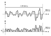
- the 'arithmetic mean roughness' is obtained by extracting the reference length L as follows in the middle average direction of the roughness curve from the roughness distribution on the surface sequentially measured from the starting point, and the average line direction is the x-axis, and the height With the direction as the y-axis, the roughness curve refers to a value expressed by Equation 1 below.
- the arithmetic mean roughness may be measured using, for example, an optical profiler (NV-2700) manufactured by Nano Systems.
- the organic-inorganic composite porous layer may be prepared by adding and dispersing nanofibers, inorganic particles having a BET specific surface area of 20 to 75 m 2 /g, and a binder polymer in a solvent for the binder polymer.
- the nanofibers, inorganic particles, and the binder polymer may be dispersed using a nanoparticle disperser.
- the nanoparticle disperser may have a bead diameter of 0.05 mm to 0.5 mm.
- the bead diameter of the nanoparticle disperser satisfies the above-mentioned range, it may be easier to disperse the nanofibers, the inorganic particles, and the binder polymer because the diameter of the beads is small. That is, since the bead diameter is large, it may be easier to prevent the nanofibers, inorganic particles, and binder polymer from being well dispersed and entangled.
- the nanofibers, inorganic particles, and the binder polymer are coated on at least one surface of the porous polymer substrate and then dried, the nanofibers first form a scaffold structure, and then, as the solvent for the binder polymer evaporates, the nanofiber scaffold Inorganic particles may be trapped in the pores of the fold.
- a lithium secondary battery may be manufactured by interposing the above-described separator for a lithium secondary battery between the positive electrode and the negative electrode.
- the lithium secondary battery may include a lithium metal secondary battery, a lithium ion secondary battery, a lithium polymer secondary battery, or a lithium ion polymer secondary battery.
- the electrode to be applied together with the separator for a lithium secondary battery of the present invention is not particularly limited, and an electrode active material layer including an electrode active material, a conductive material, and a binder is bound to a current collector according to a conventional method known in the art. can do.
- a conventional negative electrode active material that can be used in the negative electrode of a conventional lithium secondary battery can be used, and in particular, lithium metal or lithium alloy, carbon, petroleum coke, activated carbon, A lithium adsorbent material such as graphite or other carbons may be used.
- Non-limiting examples of the positive current collector include a foil made of aluminum, nickel, or a combination thereof
- non-limiting examples of the negative current collector include copper, gold, nickel, or a copper alloy or a combination thereof. There are manufactured foils and the like.
- the conductive material used in the negative electrode and the positive electrode may be typically added in an amount of 1 wt% to 30 wt% based on the total weight of each active material layer.
- a conductive material is not particularly limited as long as it has conductivity without causing a chemical change in the battery.
- graphite such as natural graphite or artificial graphite
- carbon blacks such as acetylene black, ketjen black, channel black, furnace black, lamp black, and server black
- conductive fibers such as carbon fibers and metal fibers
- carbon fluoride such as aluminum and nickel powder
- metal powders such as aluminum and nickel powder
- conductive whiskeys such as zinc oxide and potassium titanate
- conductive metal oxides such as titanium oxide
- Conductive materials such as polyphenylene derivatives may be used.
- the binder used in the negative electrode and the positive electrode is a component that assists in the bonding of the active material and the conductive material and the bonding to the current collector, and is usually 1% by weight to the total weight of each active material layer. 30% by weight may be added.
- binders examples include polyvinylidene fluoride (PVdF), polyacrylic acid (PAA), polyvinyl alcohol, carboxymethyl cellulose (CMC), starch, hydroxypropyl cellulose, regenerated cellulose, polyvinylpyrrolidone, tetrafluoro roethylene, polyethylene, polypropylene, ethylene-propylene-dienter polymer (EPDM), sulfonated EPDM, styrene butadiene rubber, fluororubber, various copolymers, and the like.
- PVdF polyvinylidene fluoride
- PAA polyacrylic acid
- CMC carboxymethyl cellulose
- EPDM ethylene-propylene-dienter polymer
- EPDM ethylene-propylene-dienter polymer
- EPDM ethylene-propylene-dienter polymer
- EPDM ethylene-propylene-dienter polymer
- sulfonated EPDM styrene
- the lithium secondary battery may include an electrolyte, and the electrolyte may include an organic solvent and a lithium salt.
- the electrolyte may include an organic solvent and a lithium salt.
- an organic solid electrolyte or an inorganic solid electrolyte may be used as the electrolyte.
- organic solvent examples include N-methyl-2-pyrrolidone, ethylene carbonate, propylene carbonate, butylene carbonate, dimethyl carbonate, diethyl carbonate, gamma-butyrolactone, 1,2-dimethoxyethane , tetrahydroxy franc, 2-methyl tetrahydrofuran, dimethyl sulfoxide, 1,3-dioxolane, formamide, dimethylformamide, dioxolane, acetonitrile, nitromethane, methyl formate, methyl acetate, phosphoric acid Triester, trimethoxymethane, dioxolane derivative, sulfolane, methyl sulfolane, 1,3-dimethyl-2-ibidazolidinone, propylene carbonate derivative, tetrahydrofuran derivative, ether, methyl pyropionate, ethyl propionate
- An aprotic organic solvent such as these may be used.
- the lithium salt is a material soluble in the organic solvent, for example, LiCl, LiBr, LiI, LiClO 4 , LiBF 4 , LiB 10 Cl 10 , LiPF 6 , LiCF 3 SO 3 , LiCF 3 CO 2 , LiAsF 6 , LiSbF 6 , LiAlCl 4 , CH 3 SO 3 Li, CF 3 SO 3 Li, (CF 3 SO 2 ) 2 Nli, lithium chloroborane, lithium lower aliphatic carboxylate, lithium 4-phenyl borate, imide, etc. can be used. have.
- pyridine triethyl phosphite, triethanolamine, cyclic ether, ethylene diamine, n-glyme, hexaphosphate triamide
- Nitrobenzene derivatives, sulfur, quinone imine dyes, N-substituted oxazolidinones, N,N-substituted imidazolidines, ethylene glycol dialkyl ethers, ammonium salts, pyrrole, 2-methoxyethanol, aluminum trichloride, etc. may be added.
- a halogen-containing solvent such as carbon tetrachloride or ethylene trifluoride may be further included, and carbon dioxide gas may be further included to improve high temperature storage characteristics.
- organic solid electrolyte examples include polyethylene derivatives, polyethylene oxide derivatives, polypropylene oxide derivatives, phosphoric acid ester polymers, polyagitation lysine, polyester sulfide, polyvinyl alcohol, polyvinylidene fluoride, A polymer containing an ionic dissociation group or the like can be used.
- Examples of the inorganic solid electrolyte include Li 3 N, LiI, Li 5 NI 2 , Li 3 N-LiI-LiOH, LiSiO 4 , LiSiO 4 -LiI-LiOH, Li 2 SiS 3 , Li 4 SiO 4 , Nitrides, halides, sulfates, etc. of Li such as Li 4 SiO 4 -LiI-LiOH, Li 3 PO 4 -Li 2 S-SiS 2 and the like may be used.
- the electrolyte injection may be performed at an appropriate stage in the battery manufacturing process according to the manufacturing process and required physical properties of the final product. That is, it may be applied before assembling the battery or in the final stage of assembling the battery.
- the separator for a lithium secondary battery may be interposed between the positive electrode and the negative electrode of the lithium secondary battery, and is interposed between adjacent cells or electrodes when a plurality of cells or electrodes are assembled to form an electrode assembly can be
- the electrode assembly may have various structures such as a simple stack type, a jelly-roll type, a stack-folding type, and a lamination-stack type.
- the separator for a lithium secondary battery may be applied to a battery in the form of an electrode assembly interposed between a positive electrode and a negative electrode.
- a process of applying the electrode assembly to a battery in addition to the general process of winding, lamination, stack, and folding processes of a separator and an electrode are possible.
- the lithium secondary battery may be a cylindrical lithium secondary battery in which the electrode assembly is wound in a cylindrical shape.
- the cylindrical lithium secondary battery may not include an electrode tab.
- the uncoated part of the electrode is welded at both ends of the cylindrical jelly roll to play the role of the tab, so the path for the electrolyte to enter the inside of the jelly roll at both ends of the jelly roll is limited.
- the electrolyte may be more difficult to impregnate.
- the diameter of the cylindrical lithium secondary battery may be 22 mm or more.
- the diameter of the cylindrical lithium secondary battery is within the above-described range, as the size of the battery increases, the electrolyte wettability needs to be higher in order to drive the battery well.
- the separator for a lithium secondary battery according to an embodiment of the present invention has excellent electrolyte wettability so that the battery can be well driven.
- Cellulose nanofibers (Hansol Paper) 20 wt%, fumed alumina (Evonik, BET specific surface area: 65 m 2 /g, average particle diameter (D50) 24 nm based on primary particles) 77 wt%, poly as a binder polymer
- a slurry for forming an organic-inorganic composite porous layer was prepared by dispersing 3 wt% of a vinyl alcohol-polyacrylic acid copolymer (LG Chem) in water using a nanomill (Nanointech, NPM) filled with zirconia beads with a diameter of 0.1 mm. (solids content of the slurry: 40% by weight).
- the slurry was coated on both sides of a polyethylene porous substrate (Senior, SW311H, thickness: 11 ⁇ m) by direct metering (Kobayashi, Direct Metering coating) and dried at 80° C. for 3 minutes to form an organic-inorganic composite porous layer. was prepared.
- a separator was prepared in the same manner as in Example 1, except that chitin nanofibers (Sigma-Aldrich) were used instead of cellulose nanofibers.
- Alumina (Daehan Ceramics, ALK-N1, BET specific surface area: 8.9 m 2 /g, average particle size based on primary particles (D50): 280 nm) 97 wt% and a polyvinyl alcohol-polyacrylic acid copolymer (LG Chem) ) 3% by weight was dispersed in water to prepare a slurry for forming an organic-inorganic composite porous layer (solid content of the slurry: 40% by weight).
- the slurry was coated on both sides of a polyethylene porous substrate (Senior, SW311H, thickness: 11 ⁇ m) by direct metering (Kobayashi, Direct Metering coating) and dried at 80° C. for 3 minutes to form an organic-inorganic composite porous layer. was prepared.
- a separator was prepared in the same manner as in Comparative Example 1, except that the same alumina as in Example 1 was used.
- a first slurry for forming an organic-inorganic composite porous layer was prepared by dispersing the weight % in water (solid content of the slurry: 40% by weight).
- the first slurry was coated on both sides of a polyethylene porous substrate (Senior, SW311H, thickness: 11 ⁇ m) by a direct metering (Kobayashi, Direct Metering coating) method and dried at 80° C. for 3 minutes, followed by the second slurry was applied and dried in the same manner to prepare a separator having an organic-inorganic composite porous layer.
- a polyethylene porous substrate Silicone, SW311H, thickness: 11 ⁇ m
- a layer containing inorganic particles and a binder polymer was formed on a porous polymer substrate, and a layer containing nanofibers and a binder polymer was formed thereon, so that two different layers were separated from each other.
- the layer containing the nanofibers and the binder polymer had a high binder content, so the resistance of the separator was increased.
- a separator was prepared in the same manner as in Example 1, except that the same alumina as in Comparative Example 1 was used.
- the BET specific surface area of the inorganic particles was less than 20 m 2 /g, so the inorganic particles could not be interposed in the pores of the nanofiber scaffold, so a layer was formed in which the inorganic particles and the nanofiber scaffold were separated.
- a separator was prepared in the same manner as in Example 1, except that a bead mill filled with zirconia beads having a diameter of 0.8 mm was used.
- Fumed alumina (Evonik, BET specific surface area: 65 m 2 /g, average particle diameter (D50) 24 nm based on primary particles) 92 wt% and polyvinyl alcohol-polyacrylic acid copolymer (LG Chem) as a binder polymer 8
- a slurry for forming an organic-inorganic composite porous layer was prepared by dispersing the weight % in water (solid content of the slurry: 40% by weight).
- the slurry was coated on both sides of a polyethylene porous substrate (Senior, SW311H, thickness 11 ⁇ m) by direct metering (Kobayashi, Direct Metering coating) and dried at 80° C. for 3 minutes to form a separator with an organic-inorganic composite porous layer. prepared.
- the organic-inorganic composite porous layer of the separator for lithium secondary batteries prepared in Examples 1 and 2 had a structure in which inorganic particles were sandwiched in the pores of the nanofiber scaffold. .
- the organic-inorganic composite porous layer of the separator for lithium secondary battery prepared in Comparative Example 1 uses inorganic particles having a BET specific surface area of less than 20 m 2 /g, and even using a small amount of binder polymer. It was confirmed that they were bound to each other.
- the organic-inorganic composite porous layer of the separator for lithium secondary batteries prepared in Comparative Example 6 had a binder content of more than 5% by weight, so that the organic-inorganic composite porous layer of the separator for lithium secondary batteries prepared in Comparative Example 2 and Otherwise, it was confirmed that cracks did not occur between the inorganic particles.
- the separators for lithium secondary batteries prepared in Examples 1 to 2 and Comparative Examples 1 to 6 were cut into a square shape of MD 10 cm x TD 10 cm, respectively, and left in a constant temperature oven maintained at 180° C. for 1 hour.
- the changing length was measured with a ruler to measure the thermal contraction rate in the machine direction (MD, Machine Direction) and the right angle direction (TD, Transverse Direction) at 180 ° C. It is shown in Table 1 below.
- the separators for lithium secondary batteries prepared in Comparative Example 2, Comparative Example 3, Comparative Example 5 and Comparative Example 6 contained inorganic particles having a BET specific surface area of 20 m 2 /g to 75 m 2 /g, and the electrolyte wettability and at 180° C. was able to secure a significant level of thermal contraction rate of the separator.
- the separator for a lithium secondary battery prepared in Comparative Example 4 contained inorganic particles having a BET specific surface area of less than 20 m 2 /g, but was able to secure a significant level of electrolyte wettability including the nanofiber scaffold. However, since the BET specific surface area of the inorganic particles was less than 20 m 2 /g, the thermal contraction rate at 180° C. was inferior to that of the Example.
- the coin cell was manufactured as follows.
- the negative electrode slurry was coated on a copper current collector with a loading amount of 3.8 mAh/cm 2 and dried to prepare a negative electrode.
- LiCoO 2 as a positive electrode active material, Denka Black as a conductive material, and polyvinylidene fluoride (PVdF) as a binder were added to N-methylpyrrolidone (NMP) as a solvent in a weight ratio of 85:5:10 to prepare a positive electrode active material slurry prepared.
- NMP N-methylpyrrolidone
- the cathode active material slurry was coated on a sheet-shaped aluminum current collector and dried to form a cathode active material layer such that the final cathode loading amount was 3.3 mAh/cm 2 .
- the separator prepared in Examples and Comparative Examples was interposed between the negative electrode and the positive electrode manufactured as described above.
- Comparative Example 6 in which the content of the binder polymer exceeds 5% by weight or more compared to 100% by weight of the organic-inorganic composite porous layer, the content of the binder polymer is 2% by weight compared to 100% by weight of the organic-inorganic composite porous layer % to 5% by weight compared to the separator prepared in Example 1, it was confirmed that the increase in resistance.
Landscapes
- Chemical & Material Sciences (AREA)
- Chemical Kinetics & Catalysis (AREA)
- Electrochemistry (AREA)
- General Chemical & Material Sciences (AREA)
- Engineering & Computer Science (AREA)
- Manufacturing & Machinery (AREA)
- Materials Engineering (AREA)
- Inorganic Chemistry (AREA)
- Composite Materials (AREA)
- Cell Separators (AREA)
- Secondary Cells (AREA)
Abstract
Description
도 1은 실시예 1에서 제조한 리튬 이차전지용 세퍼레이터의 유무기 복합 다공성층의 표면 SEM 사진이다.
도 2는 실시예 2에서 제조한 리튬 이차전지용 세퍼레이터의 유무기 복합 다공성층의 표면 SEM 사진이다.
도 3은 비교예 1에서 제조한 리튬 이차전지용 세퍼레이터의 유무기 복합 다공성층의 표면 SEM 사진이다.
도 4는 비교예 2에서 제조한 리튬 이차전지용 세퍼레이터의 유무기 복합 다공성층의 표면 SEM 사진이다.
도 5는 비교예 5에서 제조한 리튬 이차전지용 세퍼레이터의 유무기 복합 다공성층의 표면 SEM 사진이다.
도 6은 비교예 6에서 제조한 리튬 이차전지용 세퍼레이터의 유무기 복합 다공성층의 표면 SEM 사진이다.
도 7은 실시예 1에서 제조한 리튬 이차전지용 세퍼레이터의 전해액 젖음성을 나타낸 도이다.
도 8은 실시예 2에서 제조한 리튬 이차전지용 세퍼레이터의 전해액 젖음성을 나타낸 도이다.
도 9는 비교예 1에서 제조한 리튬 이차전지용 세퍼레이터의 전해액 젖음성을 나타낸 도이다.
도 10은 산술 평균 거칠기 계산 시의 거칠기 곡선을 나타낸 도이다.
[삭제]


Claims (18)
- 다공성 고분자 기재; 및상기 다공성 고분자 기재의 적어도 일면에 위치하며, 나노섬유 스캐폴드, 무기물 입자 및 바인더 고분자를 포함하는 유무기 복합 다공성층을 포함하고,상기 유무기 복합 다공성층은 상기 나노섬유 스캐폴드의 공극에 무기물 입자가 끼어 있는 구조를 가지며,상기 무기물 입자의 BET 비표면적이 20 m2/g 내지 75 m2/g이고,상기 바인더 고분자는 유무기 복합 다공성층 100 중량% 대비 2 중량% 내지 5 중량%으로 포함되는 것을 특징으로 하는 리튬 이차전지용 세퍼레이터.
- 제1항에 있어서,상기 무기물 입자의 BET 비표면적이 30 m2/g 내지 75 m2/g인 것을 특징으로 하는 리튬 이차전지용 세퍼레이터.
- 제1항에 있어서,상기 나노섬유는 친수성인 것을 특징으로 하는 리튬 이차전지용 세퍼레이터.
- 제1항에 있어서,상기 나노섬유는 소수성인 것을 특징으로 하는 리튬 이차전지용 세퍼레이터.
- 제1항에 있어서,상기 나노섬유는 유기 섬유, 무기 섬유, 또는 이들의 조합을 포함하는 것을 특징으로 하는 리튬 이차전지용 세퍼레이터.
- 제5항에 있어서,상기 유기 섬유는 셀룰로오스, 키틴, 또는 이들의 조합을 포함하는 것을 특징으로 하는 리튬 이차전지용 세퍼레이터.
- 제6항에 있어서,상기 셀룰로오스는 표면이 소수성 물질로 개질된 것을 특징으로 하는 리튬 이차전지용 세퍼레이터.
- 제5항에 있어서,상기 무기 섬유는 카본 섬유, 질화붕소 섬유, 또는 이들의 조합을 포함하는 것을 특징으로 하는 리튬 이차전지용 세퍼레이터.
- 제1항에 있어서,상기 무기물 입자의 평균 입경(D50)은 20 nm 내지 40 nm인 것을 특징으로 하는 리튬 이차전지용 세퍼레이터.
- 제1항에 있어서,상기 무기물 입자가 흄드(fumed) 알루미나, 흄드 실리카, 흄드 이산화티탄, 또는 이들 중 2 이상을 포함하는 것을 특징으로 하는 리튬 이차전지용 세퍼레이터.
- 제1항에 있어서,상기 바인더 고분자는 폴리(비닐리덴 플루오라이드-헥사플루오로프로필렌) (poly(vinylidene fluoride-co-hexafluoropropylene)), 폴리(비닐리덴 플루오라이드-클로로트리플루오로에틸렌), 폴리(비닐리덴 플루오라이드-테트라플루오로에틸렌)(poly(vinylidene fluoride-co-tetrafluoroethylene)), 폴리(비닐리덴 플루오라이드-트리클로로에틸렌) (poly(vinylidene fluoride-co-trichloroethylene)), 아크릴계 공중합체, 스티렌-부타디엔 공중합체, 폴리(아크릴산)(poly(acrylic acid)), 폴리(메틸메타크릴레이트) (poly(methylmethacrylate)), 폴리(부틸아크릴레이트) (poly(butylacrylate)), 폴리(아크릴로니트릴) (poly(acrylonitrile)), 폴리(비닐피롤리돈) (poly(vinylpyrrolidone)), 폴리(비닐알콜)(poly(vinylalcohol)), 폴리(비닐아세테이트) (poly(vinylacetate)), 에틸렌 비닐 아세테이트 공중합체 (poly(ethylene-co-vinyl acetate)), 폴리(에틸렌옥사이드) (poly(ethylene oxide)), 폴리(아릴레이트) (poly(arylate)), 셀룰로오스 아세테이트 (cellulose acetate), 셀룰로오스 아세테이트 부티레이트 (cellulose acetate butyrate), 셀룰로오스 아세테이트 프로피오네이트 (cellulose acetate propionate), 시아노에틸풀루란 (cyanoethylpullulan), 시아노에틸폴리비닐알콜(cyanoethylpolyvinylalcohol), 시아노에틸셀룰로오스 (cyanoethylcellulose), 시아노에틸수크로오스(cyanoethylsucrose), 풀루란 (pullulan), 카르복실 메틸 셀룰로오스 (carboxyl methyl cellulose), 또는 이들 중 2 이상을 포함하는 것을 특징으로 하는 리튬 이차전지용 세퍼레이터.
- 제1항에 있어서,상기 유무기 복합 다공성층은 나노입자 분산기를 사용하여 제조되고,상기 나노입자 분산기의 비드 직경이 0.05 mm 내지 0.5 mm인 것을 특징으로 하는 리튬 이차전지용 세퍼레이터.
- 제1항에 있어서,상기 유무기 복합 다공성층은 분산제를 더 포함하는 것을 특징으로 하는 리튬 이차전지용 세퍼레이터.
- 제1항에 있어서,상기 유무기 복합 다공성층의 표면의 산술 평균 거칠기가 100 nm 내지 900 nm인 것을 특징으로 하는 리튬 이차전지용 세퍼레이터.
- 양극, 음극, 및 상기 양극과 음극 사이에 개재된 세퍼레이터를 포함하는 전극 조립체를 포함하고,상기 세퍼레이터는 제1항 내지 제14항 중 어느 한 항에 따른 세퍼레이터인 것을 특징으로 하는 리튬 이차전지.
- 제15항에 있어서,상기 리튬 이차전지가 상기 전극 조립체가 원통형으로 권취되어 있는 원통형 리튬 이차전지인 것을 특징으로 하는 리튬 이차전지.
- 제16항에 있어서,상기 원통형 리튬 이차전지가 전극 탭을 포함하지 않는 것을 특징으로 하는 리튬 이차전지.
- 제16항에 있어서,상기 원통형 리튬 이차전지의 직경이 22 mm 이상인 것을 특징으로 하는 리튬 이차전지.
Priority Applications (4)
| Application Number | Priority Date | Filing Date | Title |
|---|---|---|---|
| US18/037,467 US20230411789A1 (en) | 2021-01-25 | 2022-01-25 | Separator for Lithium Secondary Battery and Lithium Secondary Battery Including the Same |
| EP22742926.3A EP4184698A4 (en) | 2021-01-25 | 2022-01-25 | SEPARATOR FOR LITHIUM SECONDARY BATTERY AND LITHIUM SECONDARY BATTERY COMPRISING SAME |
| CN202280004942.XA CN115668624A (zh) | 2021-01-25 | 2022-01-25 | 锂二次电池用隔膜以及包含所述隔膜的锂二次电池 |
| JP2022576183A JP7546701B2 (ja) | 2021-01-25 | 2022-01-25 | リチウム二次電池用セパレータ及びそれを備えたリチウム二次電池 |
Applications Claiming Priority (2)
| Application Number | Priority Date | Filing Date | Title |
|---|---|---|---|
| KR20210010311 | 2021-01-25 | ||
| KR10-2021-0010311 | 2021-01-25 |
Publications (2)
| Publication Number | Publication Date |
|---|---|
| WO2022158950A2 true WO2022158950A2 (ko) | 2022-07-28 |
| WO2022158950A3 WO2022158950A3 (ko) | 2022-09-15 |
Family
ID=82548952
Family Applications (1)
| Application Number | Title | Priority Date | Filing Date |
|---|---|---|---|
| PCT/KR2022/001333 Ceased WO2022158950A2 (ko) | 2021-01-25 | 2022-01-25 | 리튬 이차전지용 세퍼레이터 및 이를 구비한 리튬 이차전지 |
Country Status (6)
| Country | Link |
|---|---|
| US (1) | US20230411789A1 (ko) |
| EP (1) | EP4184698A4 (ko) |
| JP (1) | JP7546701B2 (ko) |
| KR (1) | KR102691032B1 (ko) |
| CN (1) | CN115668624A (ko) |
| WO (1) | WO2022158950A2 (ko) |
Cited By (2)
| Publication number | Priority date | Publication date | Assignee | Title |
|---|---|---|---|---|
| EP4481929A4 (en) * | 2022-10-24 | 2025-10-22 | Lg Energy Solution Ltd | METHOD FOR PREPARING SEPARATOR FOR LITHIUM SECONDARY BATTERY, SEPARATOR FOR LITHIUM SECONDARY BATTERY PREPARED THEREFROM, AND LITHIUM SECONDARY BATTERY COMPRISING SAME |
| JP2025541612A (ja) * | 2023-02-21 | 2025-12-22 | 香港時代新能源科技有限公司 | セパレータ、その作製方法及びそれに関連する二次電池ならびに電力消費装置 |
Families Citing this family (6)
| Publication number | Priority date | Publication date | Assignee | Title |
|---|---|---|---|---|
| CN108320916A (zh) * | 2010-08-02 | 2018-07-24 | 赛尔格有限责任公司 | 超高熔温微孔高温电池的隔板及其相关方法 |
| KR20220132309A (ko) * | 2021-03-23 | 2022-09-30 | 에스케이이노베이션 주식회사 | 복합 분리막 및 이를 이용한 전기 화학 소자 |
| KR20250038820A (ko) * | 2023-02-21 | 2025-03-19 | 컨템포러리 엠퍼렉스 테크놀로지 (홍콩) 리미티드 | 세퍼레이터, 이의 제조 방법 및 이와 관련된 이차 전지와 전기 장치 |
| KR102798556B1 (ko) * | 2023-03-24 | 2025-04-22 | 주식회사 엘지에너지솔루션 | 리튬 이차전지용 분리막의 제조방법 및 이로부터 제조된 리튬 이차전지용 분리막 및 이를 구비하는 리튬 이차전지 |
| EP4528900A4 (en) * | 2023-08-14 | 2026-03-11 | Shanghai Energy New Mat Tech Co Ltd | COMPOSITE SEPARATOR AND ITS PREPARATION PROCESS, AND BATTERY |
| CN118231948A (zh) * | 2024-03-28 | 2024-06-21 | 河南科高辐射化工科技有限公司 | 一种具有高电导率的锂离子电池复合隔膜及其制备方法 |
Citations (1)
| Publication number | Priority date | Publication date | Assignee | Title |
|---|---|---|---|---|
| KR20210010311A (ko) | 2019-07-19 | 2021-01-27 | 고려대학교 산학협력단 | Pd-l1 발현을 이용한 다발골수종 예후 예측을 위한 정보 제공 방법 |
Family Cites Families (20)
| Publication number | Priority date | Publication date | Assignee | Title |
|---|---|---|---|---|
| JP5082256B2 (ja) * | 2006-02-23 | 2012-11-28 | パナソニック株式会社 | 密閉型蓄電池 |
| KR100947072B1 (ko) * | 2008-03-27 | 2010-04-01 | 삼성에스디아이 주식회사 | 전극조립체 및 이를 구비하는 이차전지 |
| CN102388483B (zh) * | 2009-01-12 | 2016-04-06 | A123系统有限责任公司 | 叠层电池及其制备方法 |
| JP2010202987A (ja) | 2009-02-27 | 2010-09-16 | Asahi Kasei Corp | 複合シート材料及びその製法 |
| JP2012033313A (ja) * | 2010-07-29 | 2012-02-16 | Konica Minolta Holdings Inc | 二次電池積層体 |
| JP6003041B2 (ja) * | 2011-11-10 | 2016-10-05 | 日産自動車株式会社 | 耐熱絶縁層付セパレータ |
| JP6082699B2 (ja) * | 2011-11-28 | 2017-02-15 | 東レバッテリーセパレータフィルム株式会社 | 多孔質フィルム、蓄電デバイス用セパレータおよび蓄電デバイス |
| EP2820710B1 (en) * | 2012-03-02 | 2019-08-14 | Cornell University | Battery separator and method for producing same |
| HUE048838T2 (hu) * | 2012-11-30 | 2020-08-28 | Lg Chemical Ltd | Elkülönítõ szekunder telephez, amely tartalmazza különbözõ felületi jellemzõkkel bíró szervetlen részecskék kettõs porózus rétegét, az ezt tartalmazó szekunder telep, és eljárás az elkülönítõ elkészítéséhez |
| US20160319176A1 (en) * | 2014-09-17 | 2016-11-03 | National University Corporation Nagoya University | Thermally conducting composition and method for producing the same |
| DE102015200821A1 (de) * | 2015-01-20 | 2016-07-21 | Siemens Aktiengesellschaft | Hochtemperatur-Batterie |
| JP6672594B2 (ja) | 2015-03-12 | 2020-03-25 | Jnc株式会社 | 有機・無機複合膜及びこれを用いた多層耐熱セパレータ材 |
| US10468652B2 (en) * | 2015-04-22 | 2019-11-05 | Lg Chem, Ltd. | Separator for lithium secondary battery and manufacturing method therefor |
| KR102041131B1 (ko) * | 2017-04-27 | 2019-11-07 | 주식회사 엘지화학 | 이종 금속들로 이루어진 캔을 포함하는 원통형 전지셀 |
| KR102606992B1 (ko) * | 2017-09-29 | 2023-11-29 | 도레이 카부시키가이샤 | 다공성 필름, 2차전지용 세퍼레이터 및 2차전지 |
| JP6550159B1 (ja) | 2018-02-23 | 2019-07-24 | 太平洋セメント株式会社 | 二次電池用セパレータ及びその製造方法 |
| KR102209826B1 (ko) * | 2018-03-06 | 2021-01-29 | 삼성에스디아이 주식회사 | 분리막, 이의 제조방법 및 이를 포함하는 리튬전지 |
| CN112534272B (zh) | 2018-08-23 | 2024-08-16 | 株式会社日立高新技术 | 检体托架传送线和检体检查自动化系统 |
| JP7409777B2 (ja) * | 2019-03-04 | 2024-01-09 | 旭化成株式会社 | リチウムイオン二次電池用セパレータ |
| WO2020225018A1 (en) * | 2019-05-07 | 2020-11-12 | Evonik Operations Gmbh | Lithium-ion battery separator coated with surface treated alumina |
-
2022
- 2022-01-25 US US18/037,467 patent/US20230411789A1/en active Pending
- 2022-01-25 WO PCT/KR2022/001333 patent/WO2022158950A2/ko not_active Ceased
- 2022-01-25 KR KR1020220011082A patent/KR102691032B1/ko active Active
- 2022-01-25 JP JP2022576183A patent/JP7546701B2/ja active Active
- 2022-01-25 CN CN202280004942.XA patent/CN115668624A/zh active Pending
- 2022-01-25 EP EP22742926.3A patent/EP4184698A4/en active Pending
Patent Citations (1)
| Publication number | Priority date | Publication date | Assignee | Title |
|---|---|---|---|---|
| KR20210010311A (ko) | 2019-07-19 | 2021-01-27 | 고려대학교 산학협력단 | Pd-l1 발현을 이용한 다발골수종 예후 예측을 위한 정보 제공 방법 |
Cited By (2)
| Publication number | Priority date | Publication date | Assignee | Title |
|---|---|---|---|---|
| EP4481929A4 (en) * | 2022-10-24 | 2025-10-22 | Lg Energy Solution Ltd | METHOD FOR PREPARING SEPARATOR FOR LITHIUM SECONDARY BATTERY, SEPARATOR FOR LITHIUM SECONDARY BATTERY PREPARED THEREFROM, AND LITHIUM SECONDARY BATTERY COMPRISING SAME |
| JP2025541612A (ja) * | 2023-02-21 | 2025-12-22 | 香港時代新能源科技有限公司 | セパレータ、その作製方法及びそれに関連する二次電池ならびに電力消費装置 |
Also Published As
| Publication number | Publication date |
|---|---|
| WO2022158950A3 (ko) | 2022-09-15 |
| JP7546701B2 (ja) | 2024-09-06 |
| US20230411789A1 (en) | 2023-12-21 |
| JP2023529704A (ja) | 2023-07-11 |
| CN115668624A (zh) | 2023-01-31 |
| KR102691032B1 (ko) | 2024-08-05 |
| EP4184698A2 (en) | 2023-05-24 |
| EP4184698A4 (en) | 2025-05-21 |
| KR20220107983A (ko) | 2022-08-02 |
Similar Documents
| Publication | Publication Date | Title |
|---|---|---|
| WO2022158950A2 (ko) | 리튬 이차전지용 세퍼레이터 및 이를 구비한 리튬 이차전지 | |
| WO2022015026A1 (ko) | 이차전지용 세퍼레이터, 이의 제조방법 및 상기 세퍼레이터를 구비한 이차전지 | |
| WO2022019572A1 (ko) | 이차전지용 세퍼레이터, 이의 제조방법, 이를 포함하는 이차전지의 제조방법 및 이에 의해 제조된 이차전지 | |
| WO2022158951A2 (ko) | 리튬 이차전지용 세퍼레이터 및 이를 구비한 리튬 이차전지 | |
| WO2021066560A1 (ko) | 양극 및 이를 포함하는 이차 전지 | |
| WO2014104687A1 (ko) | 이차전지용 유무기 다공성분리막의 제조방법 및 이로부터 제조된 유무기 다공성분리막 | |
| WO2021251663A1 (ko) | 음극 및 이를 포함하는 이차전지 | |
| WO2021172774A1 (ko) | 탭 상에 형성된 절연필름을 포함하는 전극 조립체, 이의 제조방법, 및 이를 포함하는 리튬 이차전지 | |
| WO2022086142A1 (ko) | 분리막 및 이를 포함하는 리튬 이차 전지 | |
| WO2023008953A1 (ko) | 습윤 접착력이 우수한 절연층을 포함하는 리튬 이차전지용 양극 및 이를 포함하는 리튬 이차전지 | |
| WO2021242072A1 (ko) | 전기화학소자용 세퍼레이터 및 이를 구비한 전기화학소자 | |
| WO2020159296A1 (ko) | 절연필름을 포함하는 전극 조립체, 이의 제조방법, 및 이를 포함하는 리튬 이차전지 | |
| WO2020263023A1 (ko) | 특정한 조성 조건을 가지는 리튬 이차전지용 전극 및 이를 포함하는 리튬 이차전지 | |
| WO2022250507A1 (ko) | 전기화학소자용 세퍼레이터 및 이를 구비한 전기화학소자 | |
| WO2023120966A1 (ko) | 음극 조성물, 이를 포함하는 리튬 이차 전지용 음극 및 음극을 포함하는 리튬 이차 전지 | |
| WO2022075658A1 (ko) | 이차전지용 세퍼레이터의 제조 방법, 이로부터 제조된 세퍼레이터, 및 이를 구비한 이차전지 | |
| WO2022197125A1 (ko) | 이차 전지용 양극 슬러리 조성물, 이를 이용하여 제조된 양극 및 상기 양극을 포함하는 이차 전지 | |
| WO2023048477A1 (ko) | 이차전지용 분리막 | |
| WO2023008952A1 (ko) | 습윤 접착력이 우수한 전극용 절연 조성물, 및 이의 제조방법 | |
| WO2022050651A1 (ko) | 분리막 및 이를 포함하는 이차 전지 | |
| WO2022050801A1 (ko) | 전기화학소자용 분리막 및 이의 제조방법 | |
| WO2021206431A1 (ko) | 전기화학소자용 분리막 및 이를 제조하는 방법 | |
| WO2023153657A1 (ko) | 전기화학소자용 세퍼레이터, 이의 제조방법, 및 상기 세퍼레이터를 구비한 전기화학소자 | |
| WO2023214711A1 (ko) | 리튬 이차 전지용 음극, 리튬 이차 전지용 음극의 제조 방법 및 음극을 포함하는 리튬 이차 전지 | |
| WO2022197095A1 (ko) | 리튬 이차전지용 음극, 및 이를 구비하는 리튬 이차전지 |
Legal Events
| Date | Code | Title | Description |
|---|---|---|---|
| 121 | Ep: the epo has been informed by wipo that ep was designated in this application |
Ref document number: 22742926 Country of ref document: EP Kind code of ref document: A2 |
|
| ENP | Entry into the national phase |
Ref document number: 2022576183 Country of ref document: JP Kind code of ref document: A |
|
| ENP | Entry into the national phase |
Ref document number: 2022742926 Country of ref document: EP Effective date: 20230220 |
|
| WWE | Wipo information: entry into national phase |
Ref document number: 18037467 Country of ref document: US |
|
| NENP | Non-entry into the national phase |
Ref country code: DE |