WO2022162907A1 - 充放電計画作成装置、指令装置、電力系統管理システム、端末装置、蓄電システム、充放電システム、蓄電池、電気自動車、充放電計画作成方法および充放電計画作成プログラム - Google Patents
充放電計画作成装置、指令装置、電力系統管理システム、端末装置、蓄電システム、充放電システム、蓄電池、電気自動車、充放電計画作成方法および充放電計画作成プログラム Download PDFInfo
- Publication number
- WO2022162907A1 WO2022162907A1 PCT/JP2021/003385 JP2021003385W WO2022162907A1 WO 2022162907 A1 WO2022162907 A1 WO 2022162907A1 JP 2021003385 W JP2021003385 W JP 2021003385W WO 2022162907 A1 WO2022162907 A1 WO 2022162907A1
- Authority
- WO
- WIPO (PCT)
- Prior art keywords
- charge
- discharge
- amount
- charging
- storage batteries
- Prior art date
- Legal status (The legal status is an assumption and is not a legal conclusion. Google has not performed a legal analysis and makes no representation as to the accuracy of the status listed.)
- Ceased
Links
Images




Classifications
-
- H—ELECTRICITY
- H02—GENERATION; CONVERSION OR DISTRIBUTION OF ELECTRIC POWER
- H02J—ELECTRIC POWER NETWORKS; CIRCUIT ARRANGEMENTS OR SYSTEMS FOR SUPPLYING OR DISTRIBUTING ELECTRIC POWER; SYSTEMS FOR STORING ELECTRIC ENERGY
- H02J3/00—Circuit arrangements for AC mains or AC distribution networks
- H02J3/38—Arrangements for feeding a single network from two or more generators or sources in parallel; Arrangements for feeding already energised networks from additional generators or sources in parallel
- H02J3/46—Controlling the sharing of generated power between the generators, sources or networks
- H02J3/48—Controlling the sharing of active power
-
- B—PERFORMING OPERATIONS; TRANSPORTING
- B60—VEHICLES IN GENERAL
- B60L—PROPULSION OF ELECTRICALLY-PROPELLED VEHICLES; SUPPLYING ELECTRIC POWER FOR AUXILIARY EQUIPMENT OF ELECTRICALLY-PROPELLED VEHICLES; ELECTRODYNAMIC BRAKE SYSTEMS FOR VEHICLES IN GENERAL; MAGNETIC SUSPENSION OR LEVITATION FOR VEHICLES; MONITORING OPERATING VARIABLES OF ELECTRICALLY-PROPELLED VEHICLES; ELECTRIC SAFETY DEVICES FOR ELECTRICALLY-PROPELLED VEHICLES
- B60L53/00—Methods of charging batteries, specially adapted for electric vehicles; Charging stations or on-board charging equipment therefor; Exchange of energy storage elements in electric vehicles
- B60L53/60—Monitoring or controlling charging stations
- B60L53/63—Monitoring or controlling charging stations in response to network capacity
-
- B—PERFORMING OPERATIONS; TRANSPORTING
- B60—VEHICLES IN GENERAL
- B60L—PROPULSION OF ELECTRICALLY-PROPELLED VEHICLES; SUPPLYING ELECTRIC POWER FOR AUXILIARY EQUIPMENT OF ELECTRICALLY-PROPELLED VEHICLES; ELECTRODYNAMIC BRAKE SYSTEMS FOR VEHICLES IN GENERAL; MAGNETIC SUSPENSION OR LEVITATION FOR VEHICLES; MONITORING OPERATING VARIABLES OF ELECTRICALLY-PROPELLED VEHICLES; ELECTRIC SAFETY DEVICES FOR ELECTRICALLY-PROPELLED VEHICLES
- B60L53/00—Methods of charging batteries, specially adapted for electric vehicles; Charging stations or on-board charging equipment therefor; Exchange of energy storage elements in electric vehicles
- B60L53/50—Charging stations characterised by energy-storage or power-generation means
- B60L53/51—Photovoltaic means
-
- H—ELECTRICITY
- H02—GENERATION; CONVERSION OR DISTRIBUTION OF ELECTRIC POWER
- H02J—ELECTRIC POWER NETWORKS; CIRCUIT ARRANGEMENTS OR SYSTEMS FOR SUPPLYING OR DISTRIBUTING ELECTRIC POWER; SYSTEMS FOR STORING ELECTRIC ENERGY
- H02J3/00—Circuit arrangements for AC mains or AC distribution networks
- H02J3/003—Load forecast, e.g. methods or systems for forecasting future load demand
-
- H—ELECTRICITY
- H02—GENERATION; CONVERSION OR DISTRIBUTION OF ELECTRIC POWER
- H02J—ELECTRIC POWER NETWORKS; CIRCUIT ARRANGEMENTS OR SYSTEMS FOR SUPPLYING OR DISTRIBUTING ELECTRIC POWER; SYSTEMS FOR STORING ELECTRIC ENERGY
- H02J3/00—Circuit arrangements for AC mains or AC distribution networks
- H02J3/004—Generation forecast, e.g. methods or systems for forecasting future energy generation
-
- H—ELECTRICITY
- H02—GENERATION; CONVERSION OR DISTRIBUTION OF ELECTRIC POWER
- H02J—ELECTRIC POWER NETWORKS; CIRCUIT ARRANGEMENTS OR SYSTEMS FOR SUPPLYING OR DISTRIBUTING ELECTRIC POWER; SYSTEMS FOR STORING ELECTRIC ENERGY
- H02J3/00—Circuit arrangements for AC mains or AC distribution networks
- H02J3/17—Demand-responsive operation of AC power transmission or distribution networks
-
- H—ELECTRICITY
- H02—GENERATION; CONVERSION OR DISTRIBUTION OF ELECTRIC POWER
- H02J—ELECTRIC POWER NETWORKS; CIRCUIT ARRANGEMENTS OR SYSTEMS FOR SUPPLYING OR DISTRIBUTING ELECTRIC POWER; SYSTEMS FOR STORING ELECTRIC ENERGY
- H02J3/00—Circuit arrangements for AC mains or AC distribution networks
- H02J3/28—Arrangements for balancing of the load in networks by storage of energy
- H02J3/32—Arrangements for balancing of the load in networks by storage of energy using batteries or super capacitors with converting means
- H02J3/322—Arrangements for balancing of the load in networks by storage of energy using batteries or super capacitors with converting means the battery being on-board an electric or hybrid vehicle, e.g. vehicle to grid arrangements [V2G], power aggregation, use of the battery for network load balancing, coordinated or cooperative battery charging
-
- H—ELECTRICITY
- H02—GENERATION; CONVERSION OR DISTRIBUTION OF ELECTRIC POWER
- H02J—ELECTRIC POWER NETWORKS; CIRCUIT ARRANGEMENTS OR SYSTEMS FOR SUPPLYING OR DISTRIBUTING ELECTRIC POWER; SYSTEMS FOR STORING ELECTRIC ENERGY
- H02J3/00—Circuit arrangements for AC mains or AC distribution networks
- H02J3/38—Arrangements for feeding a single network from two or more generators or sources in parallel; Arrangements for feeding already energised networks from additional generators or sources in parallel
- H02J3/381—Dispersed generators
-
- H—ELECTRICITY
- H02—GENERATION; CONVERSION OR DISTRIBUTION OF ELECTRIC POWER
- H02J—ELECTRIC POWER NETWORKS; CIRCUIT ARRANGEMENTS OR SYSTEMS FOR SUPPLYING OR DISTRIBUTING ELECTRIC POWER; SYSTEMS FOR STORING ELECTRIC ENERGY
- H02J7/00—Circuit arrangements for charging or discharging batteries or for supplying loads from batteries
- H02J7/02—Circuit arrangements for charging or discharging batteries or for supplying loads from batteries for charging batteries from AC mains by converters
-
- H—ELECTRICITY
- H02—GENERATION; CONVERSION OR DISTRIBUTION OF ELECTRIC POWER
- H02J—ELECTRIC POWER NETWORKS; CIRCUIT ARRANGEMENTS OR SYSTEMS FOR SUPPLYING OR DISTRIBUTING ELECTRIC POWER; SYSTEMS FOR STORING ELECTRIC ENERGY
- H02J2101/00—Supply or distribution of decentralised, dispersed or local electric power generation
- H02J2101/20—Dispersed power generation using renewable energy sources
- H02J2101/22—Solar energy
- H02J2101/24—Photovoltaics
-
- H—ELECTRICITY
- H02—GENERATION; CONVERSION OR DISTRIBUTION OF ELECTRIC POWER
- H02J—ELECTRIC POWER NETWORKS; CIRCUIT ARRANGEMENTS OR SYSTEMS FOR SUPPLYING OR DISTRIBUTING ELECTRIC POWER; SYSTEMS FOR STORING ELECTRIC ENERGY
- H02J2103/00—Details of circuit arrangements for mains or AC distribution networks
- H02J2103/30—Simulating, planning, modelling, reliability check or computer assisted design [CAD] of electric power networks
- H02J2103/35—Grid-level management of power transmission or distribution systems, e.g. load flow analysis or active network management
-
- Y—GENERAL TAGGING OF NEW TECHNOLOGICAL DEVELOPMENTS; GENERAL TAGGING OF CROSS-SECTIONAL TECHNOLOGIES SPANNING OVER SEVERAL SECTIONS OF THE IPC; TECHNICAL SUBJECTS COVERED BY FORMER USPC CROSS-REFERENCE ART COLLECTIONS [XRACs] AND DIGESTS
- Y02—TECHNOLOGIES OR APPLICATIONS FOR MITIGATION OR ADAPTATION AGAINST CLIMATE CHANGE
- Y02T—CLIMATE CHANGE MITIGATION TECHNOLOGIES RELATED TO TRANSPORTATION
- Y02T10/00—Road transport of goods or passengers
- Y02T10/60—Other road transportation technologies with climate change mitigation effect
- Y02T10/70—Energy storage systems for electromobility, e.g. batteries
-
- Y—GENERAL TAGGING OF NEW TECHNOLOGICAL DEVELOPMENTS; GENERAL TAGGING OF CROSS-SECTIONAL TECHNOLOGIES SPANNING OVER SEVERAL SECTIONS OF THE IPC; TECHNICAL SUBJECTS COVERED BY FORMER USPC CROSS-REFERENCE ART COLLECTIONS [XRACs] AND DIGESTS
- Y04—INFORMATION OR COMMUNICATION TECHNOLOGIES HAVING AN IMPACT ON OTHER TECHNOLOGY AREAS
- Y04S—SYSTEMS INTEGRATING TECHNOLOGIES RELATED TO POWER NETWORK OPERATION, COMMUNICATION OR INFORMATION TECHNOLOGIES FOR IMPROVING THE ELECTRICAL POWER GENERATION, TRANSMISSION, DISTRIBUTION, MANAGEMENT OR USAGE, i.e. SMART GRIDS
- Y04S30/00—Systems supporting specific end-user applications in the sector of transportation
- Y04S30/10—Systems supporting the interoperability of electric or hybrid vehicles
- Y04S30/14—Details associated with the interoperability, e.g. vehicle recognition, authentication, identification or billing
Definitions
- the present disclosure provides a charge/discharge plan creation device, a command device, a power system management system, a terminal device, an electricity storage system, a charge/discharge system, a storage battery, an electric vehicle, a charge/discharge plan creation method, and a charge/discharge plan for creating a charge/discharge plan for a storage battery.
- a charge/discharge plan creation device a command device, a power system management system, a terminal device, an electricity storage system, a charge/discharge system, a storage battery, an electric vehicle, a charge/discharge plan creation method, and a charge/discharge plan for creating a charge/discharge plan for a storage battery.
- Patent Literature 1 discloses a technique for controlling charging and discharging of a storage battery of each consumer based on a request for power adjustment from a host control system, that is, a request for ensuring the quality of the power system.
- a host control system that is, a request for ensuring the quality of the power system.
- each consumer uses past charge/discharge commands and actual charge/discharge values. Calculate the achievement rate of the charge/discharge command in , determine the reserve capacity according to the achievement rate, and if the requested amount can be procured without using the reserve capacity, charge/discharge commands for each customer without using the reserve capacity Generate.
- the consumer must set the remaining charge of the storage battery to an appropriate value so that the charge/discharge command can be complied with. need to keep. That is, it is necessary to secure the chargeable/dischargeable amount of the storage battery.
- the appropriate value of the remaining amount of power storage varies depending on the state of each device connected to the power system and is not constant.
- the chargeable/dischargeable amount is set with a margin such as securing the available amount. For this reason, even during times when consumers are able to charge more for themselves, the amount of charge will be reduced in preparation for requests from the power system, resulting in demand for storage batteries. Constraints arise in the usability of storage batteries for homes.
- the present disclosure has been made in view of the above, and an object of the present disclosure is to obtain a charge/discharge plan creation device that can suppress the deterioration of usability of the storage battery for consumers and can use the storage battery to ensure the quality of the power system.
- a charging/discharging plan creation device provides a plurality of storage batteries calculated based on actual charge/discharge values of a plurality of storage batteries connected to an electric power system.
- a constraint determination unit that determines a constraint regarding the control amount of charge/discharge of the plurality of storage batteries for ensuring the quality of the power system, using the predicted charge/discharge amount.
- the charging/discharging plan creation device further calculates the remaining power amount of at least some of the plurality of storage batteries caused by controlling the charging/discharging of at least some of the plurality of storage batteries in order to ensure the quality of the power system and the constraints.
- a planned value calculation unit that calculates planned values of controlled variables of the plurality of storage batteries using the amount of change.
- the charging/discharging plan creation device has the effect of suppressing the deterioration of usability of the storage battery for the consumer and allowing the storage battery to be used to ensure the quality of the power system.
- FIG. 1 is a diagram showing a configuration example of a charging/discharging system according to an embodiment
- FIG. A diagram showing a configuration example of each device that configures the power grid management system Flowchart showing an example of a processing procedure in a power system management system
- Flowchart showing an example of a processing procedure of prediction processing Flowchart showing an example of a procedure for determining constraint conditions for ensuring power system quality
- Flowchart showing an example of a procedure for calculating a control amount for charging and discharging Flowchart showing an example of a control procedure of a consumer's storage battery in the command device
- a diagram schematically showing the distribution of predictive errors in controllable quantities A diagram schematically showing an example of a control cycle
- a diagram for explaining the effect of the embodiment The figure which shows the structural example of the computer system which implement
- a charge/discharge plan creation device a command device, a power system management system, a terminal device, a power storage system, a charge/discharge system, a storage battery, an electric vehicle, a charge/discharge plan creation method, and a charge/discharge plan creation program according to the embodiment are shown in drawings. will be described in detail based on
- FIG. 1 is a diagram showing a configuration example of a charging/discharging system according to an embodiment.
- the charging/discharging system of the present embodiment includes terminal devices 95 installed in the consumers 9-1 to 9-6, respectively, and charging/discharging results of the storage batteries of the consumers 9-1 to 9-6 from the terminal devices 95. and a power system management system 11 that collects various types of information about electric power including values and controls the storage batteries of consumers 9-1 to 9-6 using the collected information.
- a distribution line 1 is connected to a distribution transformer 2 to supply electric power to equipment of each consumer 9-1 to 9-6.
- the power system management system 11 uses the actual values collected from the terminal device 95 to store power in the storage batteries of the customers 9-1 to 9-6 at each time section within a certain period.
- a planned value for the charge amount is generated so as to suppress the amount of change in the remaining amount. Therefore, it is possible to create a charge/discharge plan that reflects the usage status of the storage battery of the customer 9 and suppresses the influence on the remaining amount of storage of the storage battery of each of the customers 9-1 to 9-6. There is no need to set fixed restrictions on the remaining amounts of power stored in the storage batteries of the houses 9-1 to 9-6. Therefore, the storage battery can be used to ensure the quality of the electric power system while suppressing deterioration in usability of the storage battery for the consumer.
- the power system management system 11 includes a data collection device 4, a database device 5, a prediction device 6, a charge/discharge plan creation device 7, and a command device 8.
- the data collection device 4 collects various kinds of information about the electric power of the consumers 9-1 to 9-6 from the terminal devices 95 installed in the consumers 9-1 to 9-6, respectively, and transmits the collected information to the database device 5.
- FIG. The database device 5 stores information received from the data collection device 4 , information received from the prediction device 6 , the charge/discharge plan creation device 7 and the command device 8 .
- the prediction device 6 uses the information stored in the database device 5 and the information provided from the external information providing device 20 to estimate the power consumption of the consumers 9-1 to 9-6, the power consumption of the consumers 9-1 to 9-9 -6, and transmits the prediction result to the database device 5.
- the external information providing device 20 is, for example, a device that provides weather information including actual values and forecast values of temperature and amount of solar radiation.
- the charging/discharging plan creation device 7 uses the information acquired from the database device 5 to calculate planned values for the charging/discharging amounts of the storage batteries of the consumers 9-1 to 9-6, and transmits the calculated results to the database device 5. .
- the command device 8 uses the information acquired from the database device 5 to generate a charge/discharge command for the storage battery of each consumer 9-1 to 9-6, and sends it to the terminal device 95 of each consumer 9-1 to 9-6. Send.
- the charge/discharge plan creating device 7, the command device 8, and the storage batteries of the customers 9-1 to 9-6 for which charge/discharge plans are created constitute a charge/discharge system. Details of each device constituting the power system management system 11 will be described later.
- the range managed by each of the consumers 9-1 to 9-6 includes a smart meter (abbreviated as SM in FIG. 1) 91, which is a metering device, and a solar power generation facility (PV in FIG. 1). ) 92 , a power storage system 93 , an EV charging/discharging device (abbreviated as EV in FIG. 1 ) 94 and a terminal device 95 are provided.
- SM in FIG. 1 which is a metering device, and a solar power generation facility (PV in FIG. 1).
- 92 a power storage system 93
- an EV charging/discharging device abbreviated as EV in FIG. 1
- Consumers 9-1 to 9-6 are contractors who have contracts to use electricity with electric power companies, etc., and have concluded contracts to charge and discharge storage batteries according to requests from the power system. Consumers.
- FIG. 1 the range managed by each of the consumers 9-1 to 9-6 includes a smart meter (abbreviated as SM in FIG. 1)
- each device shown in a rectangle labeled with consumers 9-1 to 9-6 is installed within a range managed by each consumer 9-1 to 9-6 or corresponding to the range. This indicates that the device is
- the range managed by each customer 9-1 to 9-6 is, for example, general households, offices, factories, hospitals, commercial facilities, charging stations, and the like.
- the distribution line 1 is, for example, a high voltage distribution line such as 6600V.
- Consumers 9-1 to 9-6 may be low-voltage consumers supplied with low-voltage electric power such as 100 V and 200 V via pole transformers (not shown) connected to the distribution line 1. However, it may be a high-voltage consumer to which high-voltage power is supplied from the distribution line 1 .
- the consumers 9-1 to 9-6 are both high-voltage consumers and low-voltage consumers will be described. It may be only the consumer.
- each of consumers 9-1 to 9-6 has a photovoltaic power generation facility 92, an electricity storage system 93, and an EV charging/discharging device 94.
- these facilities are connected to the distribution line 1 . That is, the photovoltaic power generation facility 92, the power storage system 93, and the EV charging/discharging device 94 are connected to the power system.
- all of the consumers 9-1 to 9-6 have the photovoltaic power generation equipment 92, the power storage system 93 and the EV charging/discharging device 94, but each of the consumers 9-1 to 9- 6 has at least one of the power storage system 93 and the EV charging/discharging device 94 .
- each consumer 9-1 to 9-6 also has a load, that is, equipment for consuming power, and the load is also connected to the distribution line 1.
- FIG. The power storage system 93 is, for example, a stationary power storage system installed in the consumers 9-1 to 9-6.
- Consumers 9-1 to 9-6 are examples of consumers having a storage battery, and the storage battery may be a storage battery in the power storage system 93, or a storage battery mounted on an EV that is charged and discharged by the EV charging/discharging device 94. may be That is, the storage battery of the power storage system 93 and the storage battery mounted on the EV that is charged and discharged by the EV charging/discharging device 94 are examples of a plurality of storage batteries connected to the power system.
- the storage battery of the power storage system 93 and the storage battery mounted on the EV that is charged and discharged by the EV charging/discharging device 94 are examples of storage batteries that are charged and discharged based on control commands transmitted from the power system management system 11. be.
- FIG. 1 shows equipment of a consumer 9 that charges and discharges a storage battery according to a request from the power system
- the distribution line 1 includes a customer who does not own a storage battery. Facilities of consumers other than the consumer 9 are also connected to .
- FIG. 1 shows the facilities of six consumers 9, the number of consumers 9 is not limited to the example shown in FIG.
- one distribution line 1 is illustrated in FIG. 1, the power system managed by the power system management system 11 is not limited to the distribution line 1. may contain
- the photovoltaic power generation facility 92 includes a photovoltaic panel and a PCS (Power Conditioning System) that converts the DC power generated by the photovoltaic panel into AC power.
- the power storage system 93 includes a storage battery and a storage battery PCS that is a charging/discharging device that charges and discharges the storage battery.
- the storage battery of the power storage system 93 is connected to the distribution line 1 of the power system via the storage battery PCS. It is called a connected storage battery.
- the storage battery PCS is an example of a charging/discharging device that charges/discharges a storage battery based on a charging/discharging control command transmitted from the command device 8 .
- the power generated by the photovoltaic power generation facility 92 of the consumer 9 during the daytime is consumed by the load of the consumer 9 and stored in the storage battery in the power storage system 93.
- the power stored in the power storage system 93 is It is consumed by the load of the consumer 9 at night.
- the power storage system 93 is used to keep peak power below the value required by the power company.
- each customer 9 has various purposes for installing the power storage system 93, but in the present embodiment, there is no particular restriction on the purpose for each customer 9 to install the power storage system 93. may be installed for
- the EV charging/discharging device 94 controls charging/discharging of the storage battery installed in the EV.
- the EV charging/discharging device 94 is an example of a charging/discharging device that charges/discharges a storage battery based on a charging/discharging control command transmitted from the command device 8 .
- the EV charging/discharging device 94 charges the storage battery mounted on the EV with electric power supplied from the distribution line 1, that is, the electric power system, when the EV is connected and the charging is instructed by the user. Further, the EV charging/discharging device 94 discharges the storage battery mounted on the EV when the EV is connected and the user instructs to discharge.
- the EV charging/discharging device 94 may be capable of charging the storage battery of the EV using power supplied from the power storage system 93 or the solar power generation equipment 92 . Further, two or more of the PCS in the photovoltaic power generation facility 92, the storage battery PCS in the power storage system 93, and the EV charging/discharging device 94 may be integrated.
- the smart meter 91 measures the amount of received power for automatic meter reading of the amount of power.
- the smart meter 91 transmits the amount of power received to a central device (not shown) that manages automatic meter reading.
- the smart meter 91 transmits the received power amount to the terminal device 95 .
- the smart meter 91 may transmit the amount of power received to the terminal device 95 each time it receives a data acquisition request from the terminal device 95, or may transmit the received power amount to the terminal device 95 at intervals instructed by the power system management system 11 via the terminal device 95.
- the received power amount may be voluntarily transmitted to the terminal device 95 .
- the amount of received power measured by the smart meter 91 is generally a value obtained by subtracting the amount of power supplied from the power supply source within the customer 9 from the amount of power consumed by the load of the customer 9 .
- the amount of power supplied from the power supply source in the customer 9 is the amount of power supplied by power generation by the solar power generation facility 92 of the customer 9, discharge of the power storage system 93, discharge of the storage battery of the EV, and the like.
- the terminal device 95 acquires information about power from the smart meter 91, the solar power generation equipment 92, the power storage system 93, and the EV charging/discharging device 94, and transmits the acquired information to the power system management system 11 via the communication network 10. Send to the data collection device 4 . Further, when the terminal device 95 receives a command from the command device 8 of the power system management system 11 via the communication network 10, the terminal device 95 transmits the received command to the corresponding device. For example, when the received command is a command instructing the power storage system 93 to charge/discharge, the terminal device 95 transmits the command to the power storage system 93 and sends the command to the EV charging/discharging device 94.
- the command is transmitted to the EV charging/discharging device 94 .
- the power storage system 93 and the EV charging/discharging device 94 perform charging/discharging based on the received command.
- the power storage system 93 and the EV charging/discharging device 94 may be charging/discharging before receiving a command from the command device 8.
- the received command is used to change the charging/discharging amount. It will be.
- the communication network 10 is, for example, the Internet, but is not limited to this and may be any communication network.
- the terminal device 95 acquires the actual value of the received power amount from the smart meter 91, the actual value of the power generation amount from the solar power generation equipment 92, and the power storage system 93 from the power storage system 93.
- the actual value of the charge/discharge amount and the actual value of the remaining power storage amount are acquired, and the actual value of the EV charge/discharge amount and the actual value of the remaining EV power storage amount are acquired from the EV charging/discharging device 94 .
- the amount of power generation is generated power, and its unit is W, kW, or the like.
- the charge/discharge amount of the power storage system 93 is the charge/discharge power when the storage battery of the power storage system 93 is charged/discharged, and the unit is W, kW, or the like.
- the unit is Wh, kWh, or the like.
- the EV charging/discharging amount is the charging/discharging power when the EV charging/discharging device 94 charges/discharges the EV storage battery, and the unit is W, kW, etc.
- the EV storage remaining amount is the remaining amount of the EV storage battery, and the unit is Wh. , kWh, and so on.
- the terminal device 95 periodically collects the above information and transmits it to the data collection device 4 .
- the collection cycle of these pieces of information is, for example, one minute, but the collection cycle is not limited to this.
- the charge/discharge amount of the power storage system 93 is also referred to as a storage battery charge/discharge amount
- the remaining power storage amount of the power storage system 93 is also referred to as a storage battery power storage remaining amount.
- the terminal device 95 transmits to the power system management system 11 the actual value of at least one of the plurality of storage batteries connected to the power system.
- the terminal device 95 receives from the photovoltaic power generation facility 92 , the power storage system 93 and the EV charging/discharging device 94 , the EV interconnection time, the operation of the distributed power supply, that is, the photovoltaic power generation facility 92 , the power storage system 93 and the EV charging/discharging device 94 . Also get time. Further, the terminal device 95 collects facility information regarding facilities such as the rated values of the photovoltaic power generation facility 92, the power storage system 93 and the EV charging/discharging device 94, and the storage battery capacity. Since it is not necessary to collect facility information periodically, it is carried out as appropriate, for example, when a new facility is connected to the terminal device 95 .
- the distribution line 1 is divided into a distribution section #1 and a distribution section #2 by the division switch 3, and a consumer 9- connected to the distribution section #1. 1 to 9-3 are grouped as group #1, and consumers 9-4 to 9-6 connected to power distribution section #2 are grouped as group #2.
- the consumers 9 are grouped into groups containing two or more consumers 9 .
- Group information indicating which customer 9 belongs to each group is stored in the database device 5 as equipment information. The group information may be input to the database device 5 by an operator, or may be stored in the database device 5 by being transmitted from another device (not shown). Although two groups are illustrated in FIG. 1, the number of groups is not limited to this.
- FIG. 2 is a diagram showing a configuration example of each device that constitutes the power system management system 11 of this embodiment.
- the data collection device 4 includes a communication section 41 that communicates with other devices, and a collection control section 42 that controls collection of data from the terminal device 95 .
- the collection control unit 42 uses the identification information of the terminal device 95 of the consumer 9 who owns the storage battery and has a contract to control the storage battery in response to a request from the power system. It acquires a certain terminal ID (IDentifier), and performs control for acquiring various kinds of information from the terminal device 95 using the acquired terminal ID.
- IDentifier terminal IDentifier
- the collection control unit 42 sets the collection period for collecting the received power amount, the actual value of the charge/discharge amount of the storage battery, the actual value of the remaining power storage amount of the storage battery, the actual value of the EV charge/discharge amount, and the actual value of the remaining EV power storage amount.
- the information is periodically collected from each terminal device 95 .
- the collection control unit 42 notifies each terminal device 95 of an instruction to request acquisition of these at each collection cycle.
- the communication section 41 associates them with the terminal ID and transmits them to the database device 5 as collected data.
- the data collection device 4 collects actual values of charge/discharge of a plurality of storage batteries connected to the power system.
- the actual charge/discharge value includes, for example, the actual value of the charge/discharge amount of the storage battery, the actual value of the remaining power amount of the storage battery, the actual value of the EV charge/discharge amount, and the actual value of the remaining EV power storage amount.
- the database device 5 includes a communication unit 51 that communicates with other devices, a management unit 52 that manages information, a facility information storage unit 53 that stores facility information, a contract information storage unit 54 that stores contract information, A collected data storage unit 55 that stores collected data collected by the data collection device 4, and a processed data storage unit 56 that stores each information calculated by the prediction device 6, the charge/discharge plan creation device 7, and the command device 8.
- the management unit 52 stores information received from other devices via the communication unit 51 in the corresponding storage units out of the equipment information storage unit 53, the contract information storage unit 54, the collected data storage unit 55, and the processed data storage unit 56.
- the information is stored and managed by associating the storage position with the attribute of the information.
- the management unit 52 stores the facility information storage unit 53, the contract information storage unit 54, the collected data storage unit 53, and the contract information storage unit 54 according to the attribute information specified by the request for reading information from another device received via the communication unit 51.
- the information is read from the corresponding storage unit out of the unit 55 and the processing data storage unit 56 and transmitted to the request source device via the communication unit 51 .
- the attribute information includes, for example, information indicating the type of information, information indicating date and time, and the like.
- the facility information includes information such as the connection position of the facility of each consumer 9 connected to the distribution line 1, the rating of the facility of each consumer 9, and the capacity. As described above, the ratings and capacities of the facilities of the customer 9 are acquired via, for example, the terminal device 95 and the data collection device 4, but are not limited to this, and may be input by an operator or the like, or may be input by other means (not shown). device.
- the contract information includes information such as the type of business of the customer 9, the contract type such as low voltage or high voltage, and the contract power. The contract information also includes the terminal ID of the terminal device 95 of the consumer 9 who owns the storage battery and has a contract to control the storage battery in response to a request from the power system.
- Collected data includes data collected by the data collecting device 4 and external information provided from the external information providing device 20 via the prediction device 6 . Processing data will be described later. Note that when consumers other than the consumer 9, for example, a consumer with a load, are connected to the distribution line 1, information on these consumers is also stored in the contract information.
- the device 95 and the smart meter 91 are set, and the terminal device 95 transmits the received power amount acquired from the smart meter 91 to the data collection device 4 .
- the prediction device 6 uses a communication unit 61 that communicates with other devices, the contract information and collected data stored in the database device 5, and the external information acquired from the external information providing device 20 to each customer 9
- a prediction processing unit 62 for predicting the actual load, power generation amount, charging/discharging amount, remaining power storage amount, etc., and a group counting unit 63 for calculating a prediction value for each group using the results of the prediction processing.
- the external information is, for example, weather information as described above.
- the group tallying unit 63 transmits the predicted value for each group to the database device 5 as processing data.
- the communication unit 61 also transmits the received external information to the database device 5 as collected data. Note that instead of the prediction device 6 acquiring external information from the external information providing device 20, the database device 5 acquires external information from the external information providing device 20 and stores the external information, and the prediction device 6 acquires the external information from the database device 5. External information may be obtained.
- the charging/discharging plan creation device 7 includes a communication unit 71 that communicates with other devices, and a power flow calculation unit 72 that performs power flow calculation using the prediction value for each group stored as processing data in the database device 5. Prepare. The charging/discharging plan creation device 7 further calculates the charge/discharge amounts of the plurality of storage batteries calculated based on the actual charge/discharge values of the power storage system 93 and the EV charging/discharging device 94, that is, the actual charge/discharge values of the plurality of storage batteries.
- a constraint condition determination unit 73 determines a constraint condition regarding the control amount of charging and discharging of a plurality of storage batteries for ensuring the quality of the power system; A planned value for calculating the planned value of the charge/discharge control amount for a plurality of storage batteries and a calculator 74 .
- the planned value calculation unit 74 transmits the planned value of the control amount for charging/discharging the storage battery of the customer 9 , that is, the charging/discharging plan to the database device 5 via the communication unit 71 .
- the command device 8 includes a communication unit 81 that communicates with other devices, a control amount of charging and discharging for each group stored as processing data in the database device 5, and each terminal device stored as collected data in the database device 5. and a control command generation unit 82 that generates a control command for the storage battery of each consumer 9 using various actual values transmitted from 95 and transmits the control command to the terminal device 95 via the communication unit 81 .
- the control command generation unit 82 calculates the planned value of the sum of the control amounts of the charging and discharging of the plurality of storage batteries for each group including the plurality of storage batteries connected to the electric power system, which is calculated by the charging and discharging plan creation device 7.
- a charge/discharge control command for each storage battery is generated.
- the command device 8 further generates an additional command in accordance with the deviation between the control command and the actual charge/discharge value transmitted from each terminal device 95 stored as collected data in the database device 5, and generates an additional command via the communication unit 81. and an additional command generation unit 83 for transmitting to the terminal device 95 by More specifically, the additional command generation unit 83 uses the difference between the actual value of the charge/discharge amount of the storage battery transmitted from each of the plurality of storage batteries after the transmission of the control command and the control command to respond to the control command. Generate an additional command within the control cycle to
- the functions of the power system management system 11 are realized by four devices: the data collection device 4, the database device 5, the prediction device 6, the charge/discharge plan creation device 7, and the command device 8.
- the configuration of the device for realizing the functions of the power system management system 11 is not limited to this example.
- the data collection device 4, the database device 5, the prediction device 6, the charge/discharge plan creation device 7 and the command device 8 may be integrated to be realized as one device, or two or more of these may be integrated. Alternatively, at least some of them may be configured as further subdivided devices.
- the prediction device 6 and the charge/discharge plan creation device 7 may be integrated to form a charge/discharge plan creation device.
- the data collection device 4 periodically collects information from each terminal device 95 and transmits the collected data to the database device 5 .
- the database device 5 stores the data received from the data collection device 4 in the collected data storage section 55 .
- the database device 5 also stores external information acquired from the external information providing device 20 via the prediction device 6 in the collected data storage unit 55 . These collected data are associated with dates and times.
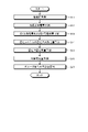
- FIG. 3 is a flow chart showing an example of a processing procedure in the power system management system 11 of this embodiment. As shown in FIG. 3, first, the prediction device 6 performs prediction processing (step S1).
- the prediction device 6 uses the collected data stored in the database device 5 to calculate the actual The load, power generation amount, charge/discharge amount of the storage battery, remaining power storage amount, and controllable amount are predicted, the prediction results are aggregated for each group, and each prediction value for each group is transmitted to the database device 5 .
- the controllable amount is an amount that indicates how much the storage battery of the customer 9 can be charged and discharged. Details of the prediction process will be described later.
- the prediction target period is, for example, the next day, but is not limited to this, and may be one year or one week.
- each time frame in the prediction target period that is, the time interval of each time slice is, for example, 30 minutes, but the time frame is not limited to this.
- each forecast value is calculated for a total of 48 time slices.
- the database device 5 stores each predicted value for each group in the processed data storage unit 56 . Details of the operation of the prediction device 6 will be described later.
- the charging/discharging plan creation device 7 determines constraints for ensuring power system quality (step S2), and determines charging/discharging change amounts (step S3). Specifically, the charging/discharging plan creation device 7 acquires the predicted value and facility information for each group from the database device 5, and performs power flow calculation using the predicted value for each group to calculate the power system during the prediction target period. Find the passing current of the facility, and if the passing current deviates from the allowable value, that is, if an overload occurs, calculate the constraint condition for calculating the charge / discharge change amount of the storage battery of the consumer 9, that is, the planned value of the control amount Then, the planned value of the charge/discharge change amount for each group is calculated using the constraint.
- the charge/discharge change amount is a change amount from the predicted value of the charge/discharge amount, and is a control amount based on a request from the power system.
- the charging/discharging plan creation device 7 determines the charging/discharging change amount, the planned value of the control amount is determined based on the request of the electric power system for the storage battery of the customer 9 in each time frame, so that the charging/discharging plan is determined.
- the charging/discharging plan creation apparatus 7 may create a demand/supply plan using the charging/discharging plan and the predicted value calculated in step S1.
- the charge/discharge plan creation device 7 transmits the charge/discharge plan to the database device 5 .
- the database device 5 stores the received charge/discharge plan in the processing data storage unit 56 .
- the charging/discharging plan creation device 7 re-determines the charging/discharging change amount on the day of charging/discharging (step S4). Specifically, the charge and discharge plan creation device 7 uses the latest actual values stored as collected data in the database device 5, etc., and predicts a certain period from the current time, such as one day from the current time. As, the processing from step S1 to step S3 may be performed again, and the latest actual values stored as collected data in the database device 5 are used to correct the created charge and discharge plan.
- the charge/discharge change amount may be re-determined. For example, in step S3, the charge/discharge change amount is re-determined with a prediction target period of 24 hours every 30 minutes.
- the charging/discharging plan creation device 7 transmits the re-determined charging/discharging plan to the database device 5 .
- the database device 5 stores the received charge/discharge plan in the processing data storage unit 56 .
- the command device 8 performs charge/discharge control (step S5). Specifically, the command device 8 uses the charge/discharge plan calculated in step S4 from the database device 5, that is, the planned value of the charge/discharge change amount for each group and the collected data, for each storage battery of each consumer 9 A control command is generated and transmitted to the corresponding terminal device 95 . Also, the command device 8 generates an additional command according to the deviation between the control command and the actual value, and transmits it to the terminal device 95 . The command device 8 may cause the database device 5 to store these data by transmitting these control commands and additional commands to the database device 5 as processing data.
- the prediction device 6 Before actually calculating predicted values such as the actual load and charge/discharge amount, the prediction device 6 obtains information such as information indicating the relationship between temperature and actual load based on past performance values for each item to be predicted. Prediction model information used for prediction is calculated in advance. There are no particular restrictions on the timing of calculating the prediction model information, and the calculation may be performed periodically, such as once a month.
- the prediction model information includes temperature correlation information, solar radiation correlation information, EV charge/discharge performance information, EV remaining power storage performance information, storage battery correlation information, and remaining power storage reference information, which will be described later. First, an example of a method for calculating prediction model information will be described.
- the prediction processing unit 62 of the prediction device 6 acquires information indicating the type of industry, contract type, contract power, etc. of each customer 9 from the database device 5 via the communication unit 61 .
- the prediction processing unit 62 of the prediction device 6 stores the performance values collected by the terminal device 95 of each consumer 9 via the communication unit 61 and the temperature and solar radiation amount of the date and time corresponding to the performance values in the database device 5. Get from The actual values are actual values of received power amount, power generation amount, storage battery charging/discharging amount, storage battery storage remaining amount, EV charging/discharging amount, and EV storage remaining amount.
- the prediction processing unit 62 may, for example, acquire all actual values stored in the database device 5, or may acquire actual values for the same season or month as the prediction target period.
- the prediction processing unit 62 extracts low-voltage consumers among the consumers 9 based on the contract type of the consumers 9, and selects the extracted consumers 9 as the consumers 9 whose business type, contract type, and contract power are all the same. are regarded as one set, and for each set, the actual load of a plurality of consumers 9 belonging to each is calculated using the received power amount, power generation amount, storage battery charge/discharge amount, and EV charge/discharge amount. Then, for each group, the average value of the actual load is obtained for each day of the week and time slot. The actual load is power consumed by the consumer 9 . Assuming that the received power is a value obtained by converting the received power amount into the power in the corresponding time period, the received power can be expressed by the following equation (1).
- the direction in which power is supplied to the consumer 9 is positive, and the direction of reverse power flow to the power system is negative. Therefore, the storage battery charge/discharge amount and the EV charge/discharge amount are positive values during charging and negative values during discharging.
- the prediction processing unit 62 obtains temperature correlation information indicating the relationship between the average value of the actual load for each day of the week and time period and the temperature for each group.
- the temperature correlation information may be a table showing the correspondence between the temperature and the actual load for each group, day of the week, and time period, or may be an expression showing the actual load as a function of the temperature.
- the temperature correlation information indicating the relationship between the average value of the actual load and the temperature is calculated for each business type, contract type, contract power, day of the week, and time period.
- a time slot is a time slot obtained by dividing a day, for example, a time slot in units of 30 minutes as in the time slot described above, but the length of the time slot is not limited to this.
- the temperature correlation information may be calculated separately for weekdays and weekends and holidays instead of for each day of the week, and the classification for calculating the temperature correlation information is not based on the type of industry, contract type, contract power and day of the week. may be classified using items other than these, or may be classified without using some of these items, and is not limited to this example.
- the prediction processing unit 62 similarly obtains the actual load of the high-voltage consumer among the consumers 9 using the above formula (1), and uses the actual load of the consumer 9 itself instead of for each group. Then, the average value of the actual load for each day of the week and time zone is obtained, and the temperature correlation information is calculated using the average value and the temperature.
- the actual load for that consumer is calculated using the actual received power amount or the received power amount and the power generation amount.
- the actual load average value is calculated by including the consumers in the group corresponding to the industry, contract type, and contract power.
- temperature correlation information is calculated for each day of the week and time period.
- the prediction processing unit 62 indicates the relationship between the amount of solar radiation and the amount of power generation by using the actual value of the amount of power generation, that is, the amount of photovoltaic power generation, and the corresponding actual value of the amount of solar radiation for each time period for each customer 9.
- Solar radiation amount correlation information is calculated.
- the solar radiation amount correlation information may also be a table or a formula showing the power generation amount as a function of the solar radiation amount.
- prediction processing unit 62 calculates an average value of the EV charge/discharge amount for each day of the week and time slot for each rating of EV charging/discharging device 94, The average value of the EV charging/discharging amount for each zone is held as EV charging/discharging performance information in, for example, a table.
- the average value for each day of the week and time period is calculated as the EV charge/discharge performance It may be calculated as information.
- the average value for each day of the week and time period is held as actual EV power storage remaining amount result information in a table, for example.
- the average value for each day of the week and time period may be stored as the EV power storage remaining amount performance information for each customer 9 .
- the prediction processing unit 62 calculates the relationship between the actual value of the storage battery charge/discharge amount for each day of the week and time zone and the actual value of "-actual load + power generation amount + EV charge/discharge amount" for each consumer 9, and calculates the storage battery correlation. Calculated as information.
- the storage battery correlation information may be a table or a relational expression.
- the direction of power generation and discharge ie, the direction of reverse power flow to the power system, is defined as positive, and the direction of power consumption and charging is defined as negative.
- the power consumption direction is assumed to be positive, the actual load is indicated by -.
- the prediction processing unit 62 includes the charge amount of the EV charge/discharge amount in the power consumption, and the relationship between the difference between the power consumption and the power generation amount and the charge/discharge amount of the storage battery at the consumer 9 as storage battery correlation information. It may be calculated and stored.
- the prediction processing unit 62 calculates the average value and variation of the actual value of the storage battery power remaining amount for each time slot for each customer 9, and calculates the time slot with the smallest variation and the average value of the time slot, respectively.
- Reference time zone and reference value Variability is, for example, variance, standard deviation, difference between maximum and minimum values.
- the prediction processing unit 62 holds the reference time period and the reference value for each consumer 9 as the remaining power amount reference information.
- the reference information on the remaining amount of stored electricity is used as a starting point for calculation when predicting the remaining amount of stored electricity in the storage system 93 on the prediction target day.
- temperature correlation information is calculated as prediction model information.
- solar radiation correlation information is calculated as prediction model information.
- EV charging/discharging performance information is calculated as prediction model information.
- EV remaining power storage performance performance information is calculated as prediction model information.
- FIG. 4 is a flowchart showing an example of the processing procedure of prediction processing according to the present embodiment.
- the prediction processing unit 62 of the prediction device 6 predicts the actual load (step S11). Specifically, the prediction processing unit 62 acquires the business type, type, contract type, and contract power from the database device 5, and acquires forecast values of temperature for each time zone in the prediction target period from the external information providing device 20. Then, the prediction processing unit 62 obtains a group belonging to each consumer 9 for the low voltage consumer, and uses the temperature correlation information and the temperature forecast value for each group, day of the week and time period to determine the day of the week in the prediction target period.
- the actual load of each consumer 9 for each time zone is predicted according to the .
- the prediction processing unit 62 similarly predicts the actual load for each time slot according to the day of the week in the prediction target period using the temperature correlation information corresponding to the consumer 9 .
- the prediction processing unit 62 of the prediction device 6 predicts the amount of photovoltaic power generation (step S12). Specifically, the prediction processing unit 62 acquires the forecast value of the amount of solar radiation for each hour of the prediction target period from the external information providing device 20 . Then, the prediction processing unit 62 predicts the amount of power generation for each consumer 9 by time period using the solar radiation amount correlation information and the solar radiation forecast value.
- the prediction processing unit 62 of the prediction device 6 predicts the EV charging/discharging amount and the remaining EV power storage amount (step S13). Specifically, the prediction processing unit 62 predicts the EV charge/discharge amount and the EV charge/discharge amount and the EV charge/discharge amount for each day of the week and time period using the EV charge/discharge performance information and the EV remaining power storage result information.
- the EV charging/discharging performance information and the EV remaining power storage performance information are average values based on the past performance for each day of the week and time period. Used as a predicted value.
- the EV charging/discharging performance information and the EV remaining power storage performance information are calculated for each consumer 9
- the EV charging/discharging performance information and the EV remaining power storage performance information corresponding to the consumer 9 are used to calculate the demand. If the EV charging/discharging performance information and the EV remaining power storage performance information for each house 9 are not calculated, the EV charging/discharging performance information and the EV storage remaining power performance information for each rating of the EV charging/discharging device 94 are used for prediction. find the value.
- the prediction processing unit 62 of the prediction device 6 predicts the charge/discharge amount of the storage battery of the power storage system 93 (step S14). Specifically, the prediction processing unit 62 uses the storage battery correlation information and the prediction values calculated in steps S11 to S13 for each consumer 9 to determine the power storage system for each time slot according to the day of the week in the prediction target period. The storage battery charge/discharge amount, which is the charge/discharge amount of 93, is predicted.
- the prediction processing unit 62 of the prediction device 6 predicts the remaining power amount of the storage battery of the power storage system 93 (step S15). Specifically, the prediction processing unit 62 obtains a reference value in the reference time period using the reference information on the remaining amount of electricity storage for each consumer 9, and calculates the reference value as the remaining amount of electricity storage of the electricity storage system 93 in the reference time period. It is assumed to be a predicted value of a certain storage battery remaining charge. The prediction processing unit 62 predicts the remaining amount of the storage battery in each time slot in the prediction target period using the reference value in the reference time slot and the storage battery charge/discharge amount in each time slot predicted in step S14.
- the prediction processing unit 62 of the prediction device 6 predicts the controllable amount (step S16). Specifically, the prediction processing unit 62 uses the predicted value of the EV charge/discharge amount and the predicted value of the storage battery charge/discharge amount calculated in steps S13 and S14 according to the following equations (2) to (5). Predicted values of the maximum permissible storage battery charge/discharge change amount, the minimum permissible storage battery charge/discharge change amount, the maximum permissible EV charge/discharge change amount, and the minimum permissible EV charge/discharge change amount are calculated as predicted values of possible amounts.
- the maximum allowable storage battery charge/discharge change amount is the maximum value of the discharge amount that can be changed from the predicted value in the storage system 93
- the discharge change amount is a value obtained by adding a minus to the maximum absolute value of the charge amount that can be changed from the predicted value in the power storage system 93 .
- the maximum permissible EV charging/discharging change amount is the maximum value of the amount of discharge that can be discharged in the EV charging/discharging device 94
- the minimum permissible EV charging/discharging change amount is the amount of charge that can be charged in the EV charging/discharging device 94. It is a value obtained by adding a minus to the maximum absolute value.
- the storage battery maximum charge amount, storage battery maximum discharge amount, EV maximum charge amount, and EV maximum discharge amount are predetermined values, for example, rated values.
- the prediction processing unit 62 of the prediction device 6 calculates a prediction value for each group (step S17). Specifically, using the group information in the equipment information stored in the database device 5, the prediction processing unit 62 uses the prediction values calculated in steps S11 to S16 for each group, which is a group for each power distribution section. are aggregated to calculate the predicted value for each group.
- the prediction processing unit 62 transmits the calculated prediction value to the database device 5, and the database device 5 stores the received prediction value in the processing data storage unit 56 as processing data.
- the prediction accuracy can be improved because the influence of the variation of the situation is reduced. For this reason, in this example, the prediction accuracy is improved by aggregating for each group.
- FIG. 5 is a flow chart showing an example of a constraint condition determination processing procedure for ensuring power system quality according to the present embodiment.
- the charging/discharging plan creation device 7 performs the following processes for each time slot in the prediction target time slot, that is, each time slice. First, the charging/discharging plan creation device 7 performs power flow calculation using each predicted value for each group (step S21). That is, the charging/discharging plan creation device 7 performs the power flow calculation using the predicted charge/discharge amount aggregated for each group and the predicted power consumption and generated power amount for each group.
- the power flow calculation unit 72 of the charge/discharge plan creation device 7 receives from the database device 5 via the communication unit 71 the actual load, power generation amount, storage charge/discharge amount, and EV storage charge in the above-described group unit in the prediction target period. Acquire the predicted value of the discharge amount and the equipment information. Then, the power flow calculation unit 72 performs power flow calculation using the acquired prediction value and information such as the connection position of each facility in the distribution system included in the facility information, and calculates the passing current of each facility in the distribution system. As a specific method of power flow calculation performed by the power flow calculation unit 72, any method such as the Newton-Raphson method and the Fast Decoupled Load Flow method can be used. methods are not limited to these.
- the power flow calculation unit 72 determines whether or not the passing current of each facility in the distribution system deviates from the allowable value (step S22).
- the permissible value is a value in the range below the maximum allowable passing current for each facility in the distribution system.
- the maximum allowable current is determined in advance and stored in the facility information. Specifically, in step S22, it is determined whether or not there is deviation from the allowable value based on whether or not the maximum allowable current is exceeded. If the passing current of each facility in the distribution system deviates from the allowable value (step S22 Yes), the charging/discharging plan creation device 7 sets the storage battery charging/discharging amount change and the EV charging/discharging amount change to each distribution system for each group. A current control amount sensitivity indicating the influence on the change in the passing current of the equipment is calculated (step S23).
- the power flow calculation unit 72 notifies the constraint determination unit 73 to that effect.
- the constraint determination unit 73 changes the storage battery charge/discharge amount by a predetermined amount, such as 1 kW, for each group, and causes the power flow calculation unit 72 to perform power flow calculation again, Calculate the amount of change in passing current of equipment that has deviated from the allowable value.
- Constraint condition determination unit 73 uses the amount of change in the charge/discharge amount of the storage battery and the amount of change in the passing current of the facility that has deviated from the allowable value, , and the amount of change in the passing current of the equipment that deviates from the allowable value when the charge/discharge amount of the storage battery is changed by 1 kW is calculated as the current control amount sensitivity. Similarly, with respect to the EV charge/discharge amount, the constraint condition determination unit 73 performs current control on the amount of change in the passing current of the equipment that deviates from the allowable value when the EV charge/discharge amount is changed by 1 kW. Calculated as volume sensitivity.
- the constraint determination unit 73 sets the storage battery charging/discharging change amount and the EV charging/discharging change amount for each group as control variables (step S24), the maximum allowable current of each facility in the distribution system, and the maximum allowable current for each group.
- a storage battery charge/discharge change amount, a minimum allowable storage battery charge/discharge change amount, a maximum allowable EV charge/discharge change amount, and a minimum allowable EV charge/discharge change amount are set as constraint conditions (step S25).
- the constraint determining unit 73 calculates the storage battery charge/discharge change amount and the EV charge/discharge change amount for each group by quadratic programming using the sum of squares of the controlled variables as an evaluation function (step S26). Specifically, the constraint determining unit 73 obtains a value obtained by squaring the change amount of the storage battery charge/discharge change amount and the EV charge/discharge change amount, that is, the change amount of the charge/discharge amount, which is the control variable of each group, and calculates the sum of these values. As an evaluation function, a storage battery charge/discharge change amount and an EV charge/discharge change amount are calculated by quadratic programming so as to minimize the evaluation function.
- the constraint determining unit 73 determines a constraint for calculating the planned value of the control amount (step S27). Specifically, the constraint determining unit 73 sets the maximum allowable battery charging/discharging change amount, the minimum allowable battery charging/discharging change amount, the maximum allowable EV charging/discharging change amount, and the minimum A permissible EV charge/discharge change amount is determined. These predicted values are calculated by the above-described formulas (2) to (5), but these predicted values can be changed using the storage battery charge/discharge change amount and the EV charge/discharge change amount calculated in step S26.
- the constraint determining unit 73 changes the constraint regarding the charge/discharge amount for each group so as to eliminate the overload.
- step S27 determines the maximum allowable storage battery charge/discharge change amount, the minimum allowable storage battery charge/discharge change amount, the maximum allowable EV charge/discharge change amount, and the minimum allowable EV charge/discharge change amount.
- the values predicted by the above equations (2) to (5) are respectively determined. In this case, the controlled variables for all power storage systems 93 and EV charging/discharging devices 94 are zero.
- processing #1 The processing shown in FIG. 5 above is referred to as processing #1, and after processing #1, the constraint condition determination unit 73 changes the set values as follows, and performs the processing assuming maximum discharge as shown in FIG. Processing #2, which is the illustrated processing, is performed.
- charge/discharge amount temp predicted value of charge/discharge amount of the storage battery + maximum allowable change amount of charge/discharge of the battery” is used to calculate the charge/discharge amount of the EV.
- step S24 the storage charge/discharge amount temp and the EV storage charge/discharge amount temp for each group are set as control variables.
- step S25 the following are set as constraints.
- Maximum allowable storage battery charge/discharge change amount temp 0 (6)
- Minimum allowable battery charge/discharge change amount temp Minimum allowable battery charge/discharge change amount -
- Maximum allowable EV charge/discharge change amount temp 0 (8)
- Minimum allowable EV charge/discharge change amount temp Minimum allowable EV charge/discharge change amount - Maximum allowable EV charge/discharge change amount (9)
- step S26 the secondary programming method is used to calculate the storage battery charge/discharge change amount temp and the EV charge/discharge change amount temp for each system group, and the results are reflected as follows.
- Maximum allowable charge/discharge change amount of storage battery Maximum allowable charge/discharge change amount of storage battery + Storage battery charge/discharge change amount temp (10)
- Maximum allowable EV charge/discharge change amount Maximum allowable EV charge/discharge change amount + EV charge/discharge change amount temp (11)
- the maximum permissible storage battery charge/discharge change amount and the maximum permissible EV charge/discharge change amount are changed according to the amount temp and the EV charge/discharge change amount temp.
- the constraint condition determination unit 73 determines process # If there is a value whose absolute value is smaller than the corresponding value calculated in step #1, the corresponding value is updated to the value calculated in process #2.
- step S24 the storage charge/discharge amount temp and the EV storage charge/discharge amount temp for each group are set as control variables.
- step S25 the following are set as constraints.
- Maximum permissible battery charge/discharge change amount temp Maximum permissible storage battery charge/discharge change amount - Minimum permissible storage battery charge/discharge change amount (12)
- Minimum allowable storage battery charge/discharge change amount temp 0 (13)
- Maximum allowable EV charge/discharge change amount temp Maximum allowable EV charge/discharge change amount - Minimum allowable EV charge/discharge change amount (14)
- Minimum allowable EV charge/discharge change amount temp 0 (15)
- step S26 the secondary programming method is used to calculate the storage battery charge/discharge change amount temp and the EV charge/discharge change amount temp for each system group, and the results are reflected as follows.
- Minimum allowable charge/discharge change amount of storage battery Minimum allowable charge/discharge change amount of storage battery + Storage battery charge/discharge change amount temp (16)
- Minimum allowable EV charge/discharge change amount Minimum allowable EV charge/discharge change amount + EV charge/discharge change amount temp (17)
- the minimum permissible storage battery charge/discharge change amount and the minimum permissible EV charge/discharge change amount are changed according to the amount temp and the EV charge/discharge change amount temp.
- the control amount assuming that the predicted value is changed in the discharging direction and the charging direction, the maximum allowable storage battery charge/discharge change amount, the minimum allowable storage battery charge/discharge change amount,
- the possible range of the control amount defined by the maximum permissible EV charge/discharge change amount and the minimum permissible EV charge/discharge change amount is narrowed step by step.
- the constraint condition determining unit 73 uses the predicted values aggregated for each group to determine the maximum allowable battery charge/discharge change amount, the minimum allowable battery charge/discharge change amount, and the maximum allowable EV A charge/discharge change amount and a minimum allowable EV charge/discharge change amount are determined.
- the constraint determining unit 73 determines the maximum permissible storage battery charge/discharge change amount, the minimum permissible storage battery charge/discharge change amount, the maximum permissible EV charge/discharge change amount, and the minimum permissible EV charge/discharge change amount, which are information indicating the determined constraint conditions. is transferred to the planned value calculation unit 74, and the planned value calculation unit 74 uses this information to calculate the planned value of the charge/discharge control amount.
- FIG. 6 is a flow chart showing an example of a calculation processing procedure of the charge/discharge control amount according to the present embodiment.
- the planned value calculator 74 sets constraints determined from the power system quality assurance request (step S31). Specifically, the planned value calculation unit 74 calculates the maximum allowable storage battery charge/discharge change amount, the minimum allowable storage battery charge/discharge change amount, the maximum allowable EV charge/discharge change amount, and the minimum allowable EV charge/discharge change amount received from the constraint determination unit 73. Using the quantity, the constraint conditions shown in the following equations (18) and (19) are set for each time zone for each group.
- the planned value calculation unit 74 sets the storage battery charging/discharging change amount and the EV charging/discharging change amount as control variables (step S33).
- EV charging/discharging amount is set as an equality constraint condition (step S34). Specifically, when there is a group for which the charge/discharge amount of the storage battery is to be changed, the planned value calculation unit 74 calculates the remaining amount of charge/discharge of the storage battery after the time slot for the change as "storage battery charge/discharge change amount x width of the time slot for the change. ” is added.
- the planned value calculation unit 74 calculates the remaining EV power storage amount after the change time period as "EV charge/discharge change amount x width of time period for change". Add the electric energy of Set these equations as equality constraints.
- the planned value calculation unit 74 sets the sum of squares of the amount of change in the remaining amount of electricity through all time slices of the prediction target period as the evaluation function (step S35), and uses the quadratic programming method to set the group A storage battery charging/discharging change amount and an EV charging/discharging change amount are calculated (step S36).
- the amount of change in the remaining amount of stored electricity is the amount of change in the remaining amount of stored electricity that changes as a result of controlling the charging and discharging of the storage battery of the consumer 9 from the power system management system 11 .
- the evaluation function is the sum of squares of the amount of change in the amount of remaining power storage through all time sections in the prediction target period, that is, the period for which the planned value is to be calculated.
- the charging/discharging plan creation device 7 transmits the storage battery charging/discharging change amount and the EV charging/discharging change amount for each time period for each group to the database device 5 as planned values of the control amount.
- step S3 the prediction process and the planned value of the charge/discharge control amount are calculated with a certain future period, such as the next day or later, as the prediction target period.
- step S4 the planned value of the charge/discharge control amount for a certain period of time, such as 24 hours from the current time period, is calculated again.
- the method of recreating the planned values may be a method of performing the same processing as the processing up to step S3 again using new actual values, or a method of recreating the calculated planned values of the charge/discharge control amount.
- a method of correcting using a new actual value may be used.
- the actual value of the most recent time period may be used as each predicted value for each customer 9 in the prediction process, and the actual value of the most recent time period may be used for correction in subsequent time periods as well.
- FIG. 7 is a flow chart showing an example of a control procedure of the storage battery of the customer 9 in the command device 8 of the present embodiment.
- the command device 8 calculates the predicted value of the load for each group using each predicted value calculated in the prediction process (step S41). Specifically, the control command generation unit 82 acquires each predicted value for each group in the time zone corresponding to the current time calculated in the prediction process from the database device 5 via the communication unit 81, and uses each predicted value. to calculate the predicted value of the load for each group.
- This load is not the actual load described above, but the power supplied to the group from the distribution line 1, that is, the value obtained by subtracting the power generated and discharged from the actual load. Therefore, the predicted value of the load of each group can be calculated by the following equation (22).
- Predicted value of load Predicted actual load - Predicted amount of power generation - Predicted amount of charge/discharge of storage battery - Predicted amount of EV charge/discharge (22)
- the command device 8 calculates the actual value of the load for each group (step S42). Specifically, the control command generation unit 82 acquires the actual value of the received power amount for the most recent fixed time period from the database device 5 via the communication unit 81, and aggregates the acquired actual value of the received power amount for each group. Then, the average value of the aggregated results over a certain period of time is calculated as the actual value of the load for each group. For example, if the received power collection cycle is 1 minute and the fixed time is 5 minutes, the actual value of the load is calculated as the average value for 5 minutes of the actual values of the received power amount aggregated for each group. Note that the command device 8 may acquire actual values directly from the data collection device 4 without going through the database device 5 .
- the command device 8 corrects the planned charge/discharge change amount for each group using the difference between the predicted load value and the actual load value (step S43). Specifically, the control command generation unit 82 uses the planned values of the storage battery charge/discharge change amount and the EV charge/discharge change amount for each group acquired from the database device 5 via the communication unit 81, The corrected storage battery charge/discharge change amount and the EV charge/discharge change amount are calculated so that the total value of the storage battery charge/discharge change amount and the EV charge/discharge change amount satisfy the following equation (23).
- both the storage battery charge/discharge change amount and the EV charge/discharge amount are corrected, but only the storage battery charge/discharge change amount is calculated using the difference between the actual load value and the predicted load value. You can fix it.
- Storage battery charge/discharge change amount after correction + EV charge/discharge change amount after correction Planned value of storage battery charge/discharge change amount + Planned value of EV charge/discharge change amount + Actual value of load - Predicted value of load (23)
- the ratio between the corrected storage battery charge/discharge change amount and the corrected EV charge/discharge change amount is determined, for example, according to the ratio between the planned value for the storage battery charge/discharge change amount and the planned value for the EV charge/discharge change amount.
- the load and the amount of power generation are also measured and predicted. may decide.
- the command device 8 determines a charge/discharge control command for each customer 9 using the corrected charge/discharge change amount and the actual charge/discharge amount (step S44). Specifically, the control command generation unit 82 acquires the actual value of the storage battery charge/discharge amount for the most recent fixed time period from the database device 5 via the communication unit 81, and calculates the corrected storage battery charge/discharge amount for each group. , the actual values of the charge/discharge amount of the storage battery and the remaining amount of power stored in the storage battery are used to determine the control command by distributing to each customer 9 . At this time, the command device 8 determines the control command in consideration of, for example, prediction errors regarding the charge/discharge amount and the remaining charge of the power storage system 93 and the EV charging/discharging device 94 .
- Parameters to be considered in controlling charging and discharging of the power storage system 93 and the EV charging and discharging device 94 include the following eight parameters. (1) Maximum permissible battery charge/discharge change (2) Minimum permissible battery charge/discharge change (3) Maximum permissible EV charge/discharge change (4) Minimum permissible EV charge/discharge change (5) Maximum permissible remaining battery charge change (6) Minimum allowable amount of change in remaining battery charge (7) Maximum allowable amount of change in remaining amount of EV charge (8) Minimum allowable amount of change in remaining charge of EV charge
- the maximum permissible storage battery charging/discharging change amount is a dischargeable amount (electric power) indicating how many more W can be discharged from the storage system 93 based on the current charging/discharging amount
- the minimum permissible storage battery charging/discharging change amount is a chargeable amount (electric power) indicating how many more W the power storage system 93 can be charged based on the current charge/discharge amount.
- the maximum permissible EV charge/discharge change amount is a dischargeable amount (electric power) indicating how many more W the EV storage battery can be discharged based on the current charge/discharge amount
- the minimum permissible EV charge/discharge change amount is a chargeable amount (electric power) indicating how many more watts the storage battery of the EV can be charged based on the current charge/discharge amount.
- the maximum permissible remaining amount of storage battery power change is a dischargeable amount (power amount) indicating how many more Wh the power storage system 93 can be discharged based on the current remaining amount of storage battery, and (6) the minimum allowable remaining amount of storage battery power.
- the amount change amount is a chargeable amount (amount of electric power) indicating how many more Wh the power storage system 93 can be charged based on the current remaining amount of power storage.
- the maximum permissible EV remaining power change amount is a dischargeable amount (power amount) indicating how many more Wh the EV storage battery can be discharged based on the current remaining power storage amount, and (8) the minimum permissible EV remaining power amount
- the amount change amount is a chargeable amount (amount of electric power) indicating how many more Wh the storage battery of the EV can be charged based on the current remaining power amount.
- the maximum allowable amount of change in the remaining amount of storage battery power (6) the minimum allowable amount of change in the amount of remaining amount of storage battery power storage, (7) the maximum allowable amount of change in the remaining amount of EV power storage, and (8) the minimum allowable amount of change in the remaining amount of EV power storage.
- the predicted value is calculated based on the predicted value of the corresponding remaining power storage amount and the predetermined minimum and maximum power storage amounts for the corresponding storage battery.
- FIG. 8 is a diagram schematically showing the distribution of predictive errors of controllable amounts according to the present embodiment.
- the controllable amount is the chargeable amount (power), dischargeable amount (power), chargeable amount (power amount), and dischargeable amount (power amount) related to the power storage system 93 and the storage battery of the EV described above.
- the amount that can be controlled as the control amount is the chargeable amount (electric power) and the dischargeable amount (electric power), but the control is subject to the remaining capacity of the storage battery. Therefore, the chargeable amount (power amount) and the dischargeable amount (power amount) as storage battery capacity are also referred to as controllable amounts.
- FIG. 8 shows the prediction error in each consumer 9 belonging to one group, that is, the deviation between the actual controllable amount and the predicted value of the controllable amount.
- the horizontal axis indicates the deviation of the controllable amount from the predicted value
- the vertical axis indicates the frequency, that is, the number of consumers 9 .
- the controllable amount is the above (2) minimum allowable storage battery charge/discharge change amount.
- the actual value of the charge/discharge amount of the power storage system 93 of each consumer 9 does not necessarily match the predicted value, and generally there is an error. For this reason, an error also occurs in (2) the minimum allowable storage battery charge/discharge change amount, which is the chargeable amount (electric power).
- the error in the chargeable amount (electric power) varies roughly randomly, so the distribution is close to a normal distribution as shown in FIG.
- the prediction error of the chargeable amount (electric power) is approximated by a normal distribution, deviation from 0 at the center of the normal distribution shown in FIG.
- the spread of the prediction error of each customer 9 from the center of the normal distribution is the variation within the customers 9 within the group.
- the control command generation unit 82 predicts the error that appears in the total of the entire group and subtracts the prediction error, which is the value of the predicted error, from the chargeable amount (electric power).
- the available amount (power) is updated, and the updated chargeable amount (power) is set as the upper limit. Therefore, when the planned value for the charge/discharge amount of the storage battery is the planned value for charging and the absolute value exceeds the chargeable amount (electric power), the control command generation unit 82 sets the absolute value to the chargeable amount (electric power). Change the planned value.
- the control command generation unit 82 calculates the normal distribution of the prediction error based on the result of applying a first-order lag filter to the actual error, which is the difference between the actual value and the predicted value, for each time period and for each group. It is calculated in advance by finding the central value in the hypothetical case. Since the normal distribution is assumed, the center of the normal distribution can be calculated as the average value of the actual values of the prediction error of each customer 9 . Alternatively, using the actual values for the same time period as the current time, apply a first-order lag filter to the actual error, which is the difference between the actual values and the predicted values, for each group to obtain the center value of the normal distribution. good.
- the control command generation unit 82 similarly obtains prediction errors for items other than (2) the minimum allowable storage battery charge/discharge change amount among the eight parameters, updates each value using the prediction errors, Set the updated value as the upper limit.
- the planned values for the storage battery charge/discharge amount and the EV charge/discharge amount for each group are updated. Depending on the prediction error, the planned values for the storage battery charge/discharge amount and the EV charge/discharge amount may not change as a result. call.
- the control command generation unit 82 sets (2) the minimum allowable storage battery charge/discharge change amount and (6) the minimum allowable storage battery charge/discharge change amount as the constraint conditions. , the unit price of storage battery charge control for each consumer 9 and the minimum allowable amount of change in the remaining amount of storage battery storage calculated from the actual value of the remaining amount of storage battery are used as evaluation items.
- the control command generation unit 82 When the charge/discharge amount of the storage battery for each group is the discharge amount, the control command generation unit 82 similarly sets (1) the maximum allowable charge/discharge change amount of the storage battery and (5) the maximum allowable storage battery charge/discharge amount change amount as the constraint conditions. , the unit price of storage battery discharge control for each consumer 9 and the maximum allowable amount of change in the remaining amount of storage battery power calculated from the actual value of the remaining amount of storage battery power are used as evaluation items. Distribute to house 9. The control command generator 82 determines the storage battery charging/discharging amount distributed to each consumer 9 as a control command for each consumer 9 . The calculation method of the control command described above is an example. The maximum permissible storage battery charge/discharge change amount may be calculated, and the planned value of the charge/discharge amount may be distributed to each consumer 9 according to the ratio of the maximum permissible storage battery charge/discharge change amount for each customer 9 .
- command device 8 transmits a control command (step S45). Specifically, the control command generation unit 82 transmits control commands corresponding to the power storage system 93 and the EV charging/discharging device 94 of each consumer 9 determined in step S44 to each consumer 9 via the communication unit 81. Send.
- the command device 8 acquires the actual value of the charge/discharge amount, predicts the deviation from the control command (step S46), determines and transmits an additional command based on the absolute value of the deviation (step S47). .
- the additional command is determined by the following procedure.
- FIG. 9 is a diagram schematically showing an example of a control cycle according to this embodiment.
- the prediction target period is shown in the upper part, and the prediction target period is divided into each time zone as described above. Therefore, planned values for the storage battery charge/discharge amount and the EV charge/discharge amount are also calculated for each time zone.
- the control cycle is shorter than one time period and longer than the actual value acquisition cycle in which the command device 8 acquires each actual value in the terminal device 95 of each customer 9 .
- the actual value acquisition cycle is, for example, the same as the data collection cycle in which the data collection device 4 acquires information from the terminal device 95, but the actual value acquisition cycle and the data collection cycle may be different.
- the command device 8 may acquire each actual value at a performance value acquisition cycle that is twice the data collection cycle.
- each consumer 9 is sent a control command for each control cycle.
- the two types of control commands for the storage battery charging/discharging amount and the EV charging/discharging amount corresponding to the same consumer 9 may be transmitted simultaneously in the same cycle, or may be transmitted in different control cycles. Note that when the consumer 9 has a plurality of power storage systems 93, the prediction is performed in steps S14 and S15 described above for each power storage system 93, and the control command and the additional command are executed for each power storage system 93 during control. is generated.
- the additional command is determined according to the deviation between the transmitted control command and the actual value, that is, the difference between the control command and the actual value, in the control cycle in which the control command was transmitted. For example, assume that the control cycle is 5 minutes and the actual value acquisition cycle is 1 minute.
- the power storage system 93 and the EV charging/discharging device 94 in each consumer 9 promptly perform charging/discharging control according to the control command if it is possible to follow the control command.
- an additional command may be similarly generated for the EV charging/discharging device 94 as well.
- the additional command generating unit 83 may transmit the additional command only to the power storage system 93 without including the EV charging/discharging device 94 in the targets for generating and transmitting the additional command.
- the control command generation unit 82 of the command device 8 transmits the control command, it notifies the additional command generation unit 83 of the control command, and the additional command generation unit 83 holds the control command.
- the additional command generator 83 uses the actual value of the storage battery charge/discharge amount obtained first after the transmission of the control command and the control command to determine the difference between the control command and the actual value, that is, the difference between the control command and the actual value. A difference is calculated and held as a divergence for each customer 9 .
- the additional command generation unit 83 holds the actual value of the storage battery charge/discharge amount acquired after the transmission of the control command.
- the additional command generation unit 83 receives the actual value of the storage battery charge/discharge amount within 1 minute after the control command is transmitted. Since the device 95 is not necessarily synchronized and delays due to communication time and various processing times are assumed, the additional command generation unit 83 calculates the charge/discharge amount of the storage battery after transmitting the control command for all the consumers 9. It is assumed that it will take a little over two minutes at the longest after the control command is sent to obtain the actual value.
- the additional command generation unit 83 calculates the integrated value for 2 minutes using the two actual values acquired from each consumer 9, that is, the actual values for 2 minutes. Then, by multiplying the integrated value for 2 minutes by 2.5, the transmission timing of the next control command, that is, the integrated value 5 minutes after the transmission of the most recent control command is predicted.
- the reason why this process is performed 3 minutes and 30 seconds after the transmission of the control command is that it takes a little over 2 minutes at the longest to acquire the actual value of the charge/discharge amount of the storage battery after the transmission of the control command, as described above. This is because it is assumed that it will take a little over 3 minutes to acquire the second actual value.
- the additional command generation unit 83 calculates the integrated value of the control commands for 5 minutes for each group, and calculates the difference between the integrated value of the control commands for 5 minutes and the predicted integrated value as the divergence from the control command.
- the addition command generation unit 83 aggregates the predicted integrated values for each group.
- the additional command generation unit 83 calculates the integrated value of the control command for 5 minutes for each group, and the difference between the integrated value of the control command for 5 minutes and the predicted integrated value is used as the deviation of each group from the control command. calculate.
- the additional command generation unit 83 calculates the controllable amount of the power storage system 93 of each consumer 9 in ascending order of the absolute value of the deviation for each consumer 9. Within the range of , an additional command is calculated for each customer 9 so as to eliminate the deviation in one minute. The additional command generation unit 83 then transmits the calculated additional command to each customer 9 via the communication unit 81 . Transmission of the additional command is performed, for example, before four minutes after transmission of the control command so that one minute corresponding to the additional command is performed within the same control cycle. That is, the processing from calculating the deviation of each group to transmitting the additional command is performed between 3 minutes and 30 seconds and 4 minutes after the transmission of the control command.
- the additional command for absorbing the deviation of the group is preferentially assigned in order of the smallest absolute value of the deviation for each customer 9
- the customer 9 that is likely to follow the control command can be preferentially selected and an additional command can be transmitted, and the probability of performing control according to the additional command can be increased.
- the numerical values such as 3 minutes and 30 seconds later and 1 minute as described above are examples, and these numerical values are set so that the deviation between the control command and the actual value can be eliminated by an additional command within the same control cycle. specific numerical values are not limited to the above examples.
- the additional command may be calculated so as to eliminate the deviation between the control command and the actual value within the control cycle, and the specific calculation method is not limited to the example described above. Further, in the above example, the deviation between the control command and the actual value is eliminated within one control cycle. Additional commands may be calculated to eliminate
- the control command generator 82 determines whether it is the next time frame, that is, the next time zone (step S48). That is, the control command generation unit 82 determines whether or not the time corresponding to the next time frame has arrived in order to update the planned value to be used, since the planned value is generated for each time zone, ie, time frame. If the next time frame has come (step S48 Yes), the process from step S41 is repeated. If it is not the next time frame (step S48 No), the control command generation unit 82 determines whether or not it is the command generation timing for each control cycle (step S49).
- step S49 since the control command is generated for each control cycle, it is determined in step S49 whether or not the time corresponding to the control cycle has elapsed. If it is the command generation timing for each control cycle (step S49 Yes), the control command generator 82 repeats the process from step S42. If No in step S49, step S49 is repeated.
- the control command When the command amount is 0, that is, when there is no control request from the electric power system, the control command may be transmitted to the consumer 9 with the command amount set to 0. No control command need be sent to the house 9 . The same applies to the additional command. If the command amount is 0, the command amount may be set to 0 and transmitted to the consumer 9, or the additional command may not be transmitted to the consumer in the corresponding control cycle.
- FIG. 10 is a diagram for explaining the effect of this embodiment.
- the horizontal axis indicates time.
- the upper part of FIG. 10 shows the active power
- the reverse flow power 301 is the reverse flow power in the sectional switch 3 of FIG.
- the lower maximum reverse power flow 201 indicates the active power corresponding to the maximum allowable current allowed for the passing current of the section switch 3 .
- the maximum discharge power 202 is a predicted value of the maximum discharge amount of the storage battery group of group #2 in FIG. 1
- the maximum charge power 203 is a prediction value of the maximum charge amount of the storage battery group of group #2 in FIG. be.
- the lower part of FIG. 10 shows the charge/discharge remaining capacity of the storage battery group of group #2. The predicted value of the remaining charge of the storage battery group of group #2 is shown.
- FIG. 11 is a diagram showing a configuration example of a computer system that implements each device that constitutes the power system management system 11 of the present embodiment.
- this computer system comprises a control section 101, an input section 102, a storage section 103, a display section 104, a communication section 105 and an output section 106, which are connected via a system bus 107.
- the control unit 101 is, for example, a CPU (Central Processing Unit) or the like, and executes a program describing the processing in each device constituting the power system management system 11 of the present embodiment.
- the input unit 102 includes, for example, a keyboard and a mouse, and is used by the user of the computer system to input various information.
- the storage unit 103 includes various memories such as RAM (Random Access Memory) and ROM (Read Only Memory) and storage devices such as hard disks, and stores programs to be executed by the control unit 101 and necessary information obtained in the course of processing. store data, etc.
- the storage unit 103 is also used as a temporary storage area for programs.
- a display unit 104 is configured by an LCD (liquid crystal display panel) or the like, and displays various screens to the user of the computer system.
- a communication unit 105 is a receiver and a transmitter that perform communication processing.
- the output unit 106 is a printer or the like.
- a program is stored in the storage unit 103 from a CD-ROM or DVD-ROM set in a CD (Compact Disc)-ROM drive or a DVD (Digital Versatile Disc)-ROM drive (not shown). installed on. Then, the program read from the storage unit 103 is stored in the storage unit 103 when the program is executed. In this state, control unit 101 executes processing as each device constituting power system management system 11 of the present embodiment according to the program stored in storage unit 103 .
- a program describing processing is provided using a CD-ROM or DVD-ROM as a recording medium.
- a program provided via a transmission medium such as the Internet via the communication unit 105 may be used.
- the communication units 41, 51, 61, 71, and 81 shown in FIG. 2 are realized by the communication unit 105 shown in FIG. 11, for example.
- the unit 83 is implemented by the control unit 101 executing a program.
- the storage unit 103 is also used for realizing these functions.
- the facility information storage unit 53, the contract information storage unit 54, the collected data storage unit 55, and the processing data storage unit 56 shown in FIG. 2 are realized by the storage unit 103 shown in FIG.
- FIG. 11 is an example, and the configuration of the computer system is not limited to the example shown in FIG. For example, the computer system may not be provided with the output unit 106 .
- each device that constitutes the power system management system 11 of the present embodiment may be realized by one computer system or may be realized by a plurality of computer systems.
- each device that configures the power system management system 11 may be realized by a cloud system.
- two or more of the devices that make up the power system management system 11 may be realized by one computer system.
- the charging/discharging plan creation program of the present embodiment provides a computer system with predicted values of charging/discharging amounts of a plurality of storage batteries calculated based on actual charging/discharging values of a plurality of storage batteries connected to an electric power system. is used to determine a constraint on the amount of charge/discharge control of a plurality of storage batteries for ensuring the quality of the power system. Further, the charging/discharging plan creation program of the present embodiment, for example, provides a computer system with a plurality of conditions generated by controlling the charging/discharging of at least a portion of a plurality of storage batteries in order to ensure the quality of the power system and the constraint conditions. and calculating a planned value of the control amount of the plurality of storage batteries using the amount of change in the remaining power of at least some of the storage batteries.
- the terminal device 95 includes, for example, at least the control unit 101, the storage unit 103, and the communication unit 105 of the configuration example shown in FIG.
- the functions of the terminal device 95 are realized by the control unit 101 executing a program for realizing the operation of the terminal device 95 stored in the storage unit 103 .
- the power system management system 11 uses the predicted value based on the actual charge/discharge value collected from the terminal device 95, and the storage battery of the consumer 9 at each time within a certain period.
- a planned value for the amount of charge is generated so as to suppress the amount of change in the amount of charge remaining in the storage battery at the cross section. Therefore, since it is possible to create a charge/discharge plan that reflects the usage status of the storage battery of the customer 9 and suppresses the influence on the remaining amount of storage of the storage battery of each customer 9, the storage battery of the customer 9 can be stored in advance. There is no need to set a fixed constraint on the remaining amount. Therefore, deterioration of usability of the storage battery for the consumer 9 can be suppressed, and the storage battery can be used to ensure the quality of the power system.
Landscapes
- Engineering & Computer Science (AREA)
- Power Engineering (AREA)
- Transportation (AREA)
- Mechanical Engineering (AREA)
- Charge And Discharge Circuits For Batteries Or The Like (AREA)
- Supply And Distribution Of Alternating Current (AREA)
Abstract
Description
受電電力=実負荷-発電量+蓄電池充放電量+EV充放電量 ・・・(1)
= 蓄電池最大充電量 - 蓄電池充放電量の予測値 ・・・(2)
最小許容蓄電池充放電変更量の予測値
= -蓄電池最大放電量 - 蓄電池充放電量の予測値 ・・・(3)
最大許容EV充放電変更量の予測値
= EV最大充電量 - EV充放電量の予測値 ・・・(4)
最小許容EV充放電変更量の予測値
= -EV最大放電量 - EV充放電量の予測値 ・・・(5)
最大許容蓄電池充放電変更量temp = 0 ・・・(6)
最小許容蓄電池充放電変更量temp = 最小許容蓄電池充放電変更量 ― 最大許容蓄電池充放電変更量 ・・・(7)
最大許容EV充放電変更量temp = 0 ・・・(8)
最小許容EV充放電変更量temp = 最小許容EV充放電変更量 ― 最大許容EV充放電変更量 ・・・(9)
最大許容蓄電池充放電変更量 = 最大許容蓄電池充放電変更量 + 蓄電池充放電変更量temp ・・・(10)
最大許容EV充放電変更量 = 最大許容EV充放電変更量 + EV充放電変更量temp ・・・(11)
最大許容蓄電池充放電変更量temp = 最大許容蓄電池充放電変更量 ― 最小許容蓄電池充放電変更量 ・・・(12)
最小許容蓄電池充放電変更量temp = 0 ・・・(13)
最大許容EV充放電変更量temp = 最大許容EV充放電変更量 ― 最小許容EV充放電変更量 ・・・(14)
最小許容EV充放電変更量temp = 0 ・・・(15)
最小許容蓄電池充放電変更量 = 最小許容蓄電池充放電変更量 + 蓄電池充放電変更量temp ・・・(16)
最小許容EV充放電変更量 = 最小許容EV充放電変更量 + EV充放電変更量temp ・・・(17)
最小許容蓄電池充放電変更量 <= 蓄電池充放電変更量 <= 最大許容蓄電池充放電変更量 ・・・(18)
最小許容EV充放電変更量 <= EV充放電変更量 <= 最大許容EV充放電変更量 ・・・(19)
最小許容蓄電池蓄電残量 <= 蓄電池蓄電残量 <= 最大許容蓄電池蓄電残量 ・・・(20)
最小許容EV蓄電残量 <= EV蓄電残量 <= 最大許容EV蓄電残量 ・・・(21)
負荷の予測値 = 実負荷の予測値 - 発電量の予測値 - 蓄電池充放電量の予測値 - EV充放電量の予測値 ・・・(22)
修正後の蓄電池充放電変更量 + 修正後のEV充放電変更量
= 蓄電池充放電変更量の計画値 + EV充放電変更量の計画値
+ 負荷の実績値 - 負荷の予測値 ・・・(23)
(1)最大許容蓄電池充放電変更量
(2)最小許容蓄電池充放電変更量
(3)最大許容EV充放電変更量
(4)最小許容EV充放電変更量
(5)最大許容蓄電池蓄電残量変更量
(6)最小許容蓄電池蓄電残量変更量
(7)最大許容EV蓄電残量変更量
(8)最小許容EV蓄電残量変更量
Claims (18)
- 電力系統に接続される複数の蓄電池の充放電の実績値に基づいて算出される前記複数の蓄電池の充放電量の予測値を用いて、電力系統の品質確保のための前記複数の蓄電池の充放電の制御量に関する制約条件を決定する制約条件決定部と、
前記制約条件と電力系統の品質確保のために前記複数の蓄電池のうち少なくとも一部の充放電を制御することにより生じる前記複数の蓄電池のうち少なくとも一部の蓄電残量の変化量とを用いて前記複数の蓄電池の制御量の計画値を算出する計画値算出部と、
を備えることを特徴とする充放電計画作成装置。 - 前記複数の蓄電池は、それぞれに対応する需要家により使用される蓄電池であり、
前記複数の蓄電池は、2以上の前記需要家を含むグループにグループ分けされ、
前記制約条件決定部は、前記グループごとに集計された前記予測値を用いて前記グループごとの前記制約条件を決定し、
前記計画値算出部は、前記グループごとに、前記グループに属する前記蓄電池の制御量の総和を前記計画値として算出することを特徴とする請求項1に記載の充放電計画作成装置。 - 前記計画値算出部は、前記計画値の算出対象の期間における各前記グループの前記変化量の二乗和を評価関数として、二次計画法により前記計画値を算出することを特徴とする請求項2に記載の充放電計画作成装置。
- 前記グループごとの前記予測値の集計結果と、前記グループごとの消費電力および発電量の予測値とを用いて潮流計算を行う潮流計算部、
を備え、
前記制約条件決定部は、前記潮流計算の結果、前記電力系統に過負荷が発生すると予測される場合、前記過負荷を解消するように前記グループ単位の充放電量に関する前記制約条件を変更することを特徴とする請求項2または3に記載の充放電計画作成装置。 - 前記複数の蓄電池は、需要家に設置される定置用蓄電システムにおける蓄電池を含むことを特徴とする請求項1から4のいずれか1つに記載の充放電計画作成装置。
- 前記実績値は、前記複数の蓄電池の充放電量の実績値と、前記複数の蓄電池の蓄電残量の実績値と、を含み、
前記充放電計画作成装置は、
前記蓄電池に対応する前記需要家における消費電力と発電量との差と、前記需要家における前記蓄電池の充放電量との関係を示す蓄電池相関情報を保持し、前記蓄電池相関情報と前記需要家における消費電力の予測値と前記需要家における発電量の予測値とを用いて前記蓄電池の充放電量の予測値を算出する予測処理部、
を備えることを特徴とする請求項5に記載の充放電計画作成装置。 - 前記複数の蓄電池は、電気自動車に搭載される蓄電池を含むことを特徴とする請求項1から5のいずれか1つに記載の充放電計画作成装置。
- 請求項2から4のいずれか1つに記載の充放電計画作成装置によって算出された、電力系統に接続される複数の蓄電池を含むグループごとの前記複数の蓄電池の充放電の制御量の総和の計画値と、前記複数の蓄電池のそれぞれから送信された前記蓄電池の充放電量の実績値とを用いて、前記蓄電池ごとの充放電の制御指令を生成する制御指令生成部と、
前記制御指令を前記蓄電池の充放電を行う充放電装置へ送信する通信部と、
を備えることを特徴とする指令装置。 - 前記制御指令生成部は、制御周期ごとに前記制御指令を生成し、
前記指令装置は、
前記制御指令の送信後の前記複数の蓄電池のそれぞれから送信された前記蓄電池の充放電量の実績値と、前記制御指令との差を用いて、当該制御指令に対応する前記制御周期内で追加指令を生成する追加指令生成部、
を備え、
前記通信部は、前記追加指令を対応する前記充放電装置へ送信することを特徴とする請求項8に記載の指令装置。 - 請求項1から4のいずれか1つに記載の充放電計画作成装置と、
前記充放電計画作成装置によって算出された蓄電池の充放電の制御量の計画値を用いて、前記蓄電池に対する充放電の制御指令に基づいて前記蓄電池の充放電を行う充放電装置へ送信する指令装置と、
を備えることを特徴とする電力系統管理システム。 - 電力系統に接続される複数の蓄電池の充放電の実績値を収集するデータ収集装置と、
前記実績値を用いて複数の蓄電池の充放電の制御量の計画値を算出する充放電計画作成装置と、
を備え、
前記充放電計画作成装置は、
前記実績値に基づいて算出される前記複数の蓄電池の充放電量の予測値を用いて、電力系統の品質確保のための前記複数の蓄電池の充放電の制御量に関する制約条件を決定する制約条件決定部と、
前記制約条件と電力系統の品質確保のために前記複数の蓄電池のうち少なくとも一部の充放電を制御することにより生じる前記複数の蓄電池のうち少なくとも一部の蓄電残量の変化量とを用いて前記計画値を算出する計画値算出部と、
を備えることを特徴とする電力系統管理システム。 - 電力系統に接続される複数の蓄電池の充放電の実績値に基づいて算出される前記複数の蓄電池の充放電量の予測値を用いて、電力系統の品質確保のための前記複数の蓄電池の充放電の制御量に関する制約条件を決定し、前記制約条件と電力系統の品質確保のために前記複数の蓄電池のうち少なくとも一部の充放電を制御することにより生じる前記複数の蓄電池のうち少なくとも一部の蓄電残量の変化量とを用いて前記複数の蓄電池の制御量の計画値を算出する電力系統管理システムへ、前記複数の蓄電池のうちの少なくとも1つの前記実績値を送信することを特徴とする端末装置。
- 電力系統に接続される複数の蓄電池のうちの1つの前記蓄電池を備える蓄電システムであって、
充放電の実績値に基づいて算出される前記複数の蓄電池の充放電量の予測値を用いて、電力系統の品質確保のための前記複数の蓄電池の充放電の制御量に関する制約条件を決定し、前記制約条件と電力系統の品質確保のために前記複数の蓄電池のうち少なくとも一部の充放電を制御することにより生じる前記複数の蓄電池のうち少なくとも一部の蓄電残量の変化量とを用いて前記複数の蓄電池の制御量の計画値を算出し、前記計画値を用いて前記蓄電池の充放電の制御指令を送信する電力系統管理システムから自身に対応する前記制御指令を受信し、受信した前記制御指令に基づいて前記蓄電池の充放電を行うことを特徴とする蓄電システム。 - 電力系統に接続される複数の蓄電池と、
前記複数の蓄電池の充放電の実績値に基づいて算出される前記複数の蓄電池の充放電量の予測値を用いて、電力系統の品質確保のための前記複数の蓄電池の充放電の制御量に関する制約条件を決定し、前記制約条件と電力系統の品質確保のために前記複数の蓄電池のうち少なくとも一部の充放電を制御することにより生じる前記複数の蓄電池のうち少なくとも一部の蓄電残量の変化量とを用いて前記複数の蓄電池の制御量の計画値を算出する充放電計画作成装置と、
を備えることを特徴とする充放電システム。 - 電力系統に接続される複数の蓄電池のうちの1つの前記蓄電池であって、
請求項10に記載の電力系統管理システムから送信された制御指令に基づいて充放電が行われることを特徴とする蓄電池。 - 請求項15に記載の蓄電池を搭載することを特徴とする電気自動車。
- 充放電計画作成装置における充放電計画作成方法であって、
電力系統に接続される複数の蓄電池の充放電の実績値に基づいて算出される前記複数の蓄電池の充放電量の予測値を用いて、電力系統の品質確保のための前記複数の蓄電池の充放電の制御量に関する制約条件を決定するステップと、
前記制約条件と電力系統の品質確保のために前記複数の蓄電池のうち少なくとも一部の充放電を制御することにより生じる前記複数の蓄電池のうち少なくとも一部の蓄電残量の変化量とを用いて前記複数の蓄電池の制御量の計画値を算出するステップと、
を含むことを特徴とする充放電計画作成方法。 - コンピュータシステムに、
電力系統に接続される複数の蓄電池の充放電の実績値に基づいて算出される前記複数の蓄電池の充放電量の予測値を用いて、電力系統の品質確保のための前記複数の蓄電池の充放電の制御量に関する制約条件を決定するステップと、
前記制約条件と電力系統の品質確保のために前記複数の蓄電池のうち少なくとも一部の充放電を制御することにより生じる前記複数の蓄電池のうち少なくとも一部の蓄電残量の変化量とを用いて前記複数の蓄電池の制御量の計画値を算出するステップと、
を実行させることを特徴とする充放電計画作成プログラム。
Priority Applications (7)
| Application Number | Priority Date | Filing Date | Title |
|---|---|---|---|
| US18/259,420 US20240059172A1 (en) | 2021-01-29 | 2021-01-29 | Charge/discharge plan creation device, command device, power grid management system, terminal device, power storage system, charge/discharge system, storage battery, electric vehicle, charge/discharge plan creation method, and storage medium |
| EP21922922.6A EP4287442A4 (en) | 2021-01-29 | 2021-01-29 | CHARGE/DISCHARGE PLAN CREATION DEVICE, CONTROL DEVICE, POWER SYSTEM MANAGEMENT SYSTEM, TERMINAL DEVICE, ENERGY STORAGE SYSTEM, CHARGE/DISCHARGE SYSTEM, ENERGY STORAGE CELL, ELECTRIC VEHICLE, METHOD FOR CREATING A CHARGING/DISCHARGING PLAN AND PROGRAM FOR CREATING A CHARGING/DISCHARGING PLAN |
| PCT/JP2021/003385 WO2022162907A1 (ja) | 2021-01-29 | 2021-01-29 | 充放電計画作成装置、指令装置、電力系統管理システム、端末装置、蓄電システム、充放電システム、蓄電池、電気自動車、充放電計画作成方法および充放電計画作成プログラム |
| MYPI2023004380A MY206812A (en) | 2021-01-29 | 2021-01-29 | Charge/discharge plan creation device, command device, power grid management system, terminal device, power storage system, charge/discharge system, storage battery, electric vehicle, charge/discharge plan creation method, and charge/discharge plan creation program |
| JP2021536246A JP6942295B1 (ja) | 2021-01-29 | 2021-01-29 | 充放電計画作成装置、指令装置、電力系統管理システム、端末装置、蓄電システム、充放電システム、蓄電池、電気自動車、充放電計画作成方法および充放電計画作成プログラム |
| AU2021423472A AU2021423472B2 (en) | 2021-01-29 | 2021-01-29 | Charge/discharge plan creation device, command device, power grid management system, terminal device, power storage system, charge/discharge system, storage battery, electric vehicle, charge/discharge plan creation method, and charge/discharge plan creation program |
| TW111100550A TWI810778B (zh) | 2021-01-29 | 2022-01-06 | 充放電計劃作成裝置、指令裝置、電力系統管理系統、終端裝置、蓄電系統、充放電系統、蓄電池、電動車、充放電計劃作成方法及記錄媒體 |
Applications Claiming Priority (1)
| Application Number | Priority Date | Filing Date | Title |
|---|---|---|---|
| PCT/JP2021/003385 WO2022162907A1 (ja) | 2021-01-29 | 2021-01-29 | 充放電計画作成装置、指令装置、電力系統管理システム、端末装置、蓄電システム、充放電システム、蓄電池、電気自動車、充放電計画作成方法および充放電計画作成プログラム |
Publications (1)
| Publication Number | Publication Date |
|---|---|
| WO2022162907A1 true WO2022162907A1 (ja) | 2022-08-04 |
Family
ID=77847056
Family Applications (1)
| Application Number | Title | Priority Date | Filing Date |
|---|---|---|---|
| PCT/JP2021/003385 Ceased WO2022162907A1 (ja) | 2021-01-29 | 2021-01-29 | 充放電計画作成装置、指令装置、電力系統管理システム、端末装置、蓄電システム、充放電システム、蓄電池、電気自動車、充放電計画作成方法および充放電計画作成プログラム |
Country Status (7)
| Country | Link |
|---|---|
| US (1) | US20240059172A1 (ja) |
| EP (1) | EP4287442A4 (ja) |
| JP (1) | JP6942295B1 (ja) |
| AU (1) | AU2021423472B2 (ja) |
| MY (1) | MY206812A (ja) |
| TW (1) | TWI810778B (ja) |
| WO (1) | WO2022162907A1 (ja) |
Cited By (4)
| Publication number | Priority date | Publication date | Assignee | Title |
|---|---|---|---|---|
| JP2024065886A (ja) * | 2022-10-31 | 2024-05-15 | 本田技研工業株式会社 | 充電率推定方法 |
| TWI860687B (zh) * | 2022-09-29 | 2024-11-01 | 日商日立全球先端科技股份有限公司 | 充電計畫作成方法、充電計畫作成裝置及充電計畫提供系統 |
| WO2024251811A1 (de) * | 2023-06-05 | 2024-12-12 | enspired GmbH | System zur steuerung einer lade- und/oder entladeleistung wenigstens eines energiespeichers |
| WO2025243740A1 (ja) * | 2024-05-20 | 2025-11-27 | パナソニックIpマネジメント株式会社 | 充電計画の支援方法、充電計画の支援装置、充電計画方法、発電計画の支援方法、及び、発電計画の支援装置 |
Families Citing this family (9)
| Publication number | Priority date | Publication date | Assignee | Title |
|---|---|---|---|---|
| US12500436B2 (en) * | 2021-10-20 | 2025-12-16 | China Energy Investment Corporation Limited | Controller, system, and method for managing discharge or charge of heterogeneous battery packs |
| KR102810194B1 (ko) * | 2022-01-03 | 2025-05-22 | 고려대학교 산학협력단 | 재생에너지 보급 증가 환경에서의 송전계통운영 및 배전계통운영 협조 방법 |
| JP7752552B2 (ja) * | 2022-03-07 | 2025-10-10 | 大阪瓦斯株式会社 | 電源管理システム、燃料電池装置及び充放電装置 |
| JPWO2024090238A1 (ja) * | 2022-10-26 | 2024-05-02 | ||
| KR102914126B1 (ko) * | 2022-12-19 | 2026-01-20 | 한국과학기술원 | 전기차 충방전 스케줄링 알고리즘 기반 전력 관리 시스템 및 그 방법 |
| JP7695569B2 (ja) * | 2023-04-25 | 2025-06-19 | 日新電機株式会社 | モデル生成装置、予測装置、モデル生成方法、および予測方法 |
| JP2025039145A (ja) * | 2023-09-08 | 2025-03-21 | 株式会社日立製作所 | 電力融通システム |
| CN120517246B (zh) * | 2025-05-15 | 2026-03-24 | 惠州市万物互联科技有限公司 | 一种智能光伏充电桩的控制方法与系统 |
| JP7801523B1 (ja) * | 2025-05-20 | 2026-01-16 | Nttアノードエナジー株式会社 | 制御システム |
Citations (5)
| Publication number | Priority date | Publication date | Assignee | Title |
|---|---|---|---|---|
| JP2012060835A (ja) * | 2010-09-10 | 2012-03-22 | Kansai Electric Power Co Inc:The | 蓄電装置制御装置 |
| JP2015220862A (ja) * | 2014-05-16 | 2015-12-07 | トヨタ自動車株式会社 | 電力管理システム |
| JP2018148679A (ja) * | 2017-03-03 | 2018-09-20 | 株式会社日立製作所 | アグリゲーション制御システム、アグリゲーション制御方法及び制御装置 |
| JP2020089087A (ja) | 2018-11-27 | 2020-06-04 | 積水化学工業株式会社 | 電力管理方法および電力管理システム |
| JP2020195166A (ja) * | 2019-05-24 | 2020-12-03 | 株式会社日立パワーソリューションズ | 再生可能エネルギー発電機指令コントローラおよび蓄電池併設再生可能エネルギー発電機システム |
Family Cites Families (2)
| Publication number | Priority date | Publication date | Assignee | Title |
|---|---|---|---|---|
| JP4445361B2 (ja) * | 2004-09-24 | 2010-04-07 | 関西電力株式会社 | 二次電池を用いた電力系統制御方法及び電力系統制御装置 |
| US9444256B2 (en) * | 2013-03-01 | 2016-09-13 | Semiconductor Energy Laboratory Co., Ltd. | Power storage system |
-
2021
- 2021-01-29 US US18/259,420 patent/US20240059172A1/en active Pending
- 2021-01-29 WO PCT/JP2021/003385 patent/WO2022162907A1/ja not_active Ceased
- 2021-01-29 MY MYPI2023004380A patent/MY206812A/en unknown
- 2021-01-29 AU AU2021423472A patent/AU2021423472B2/en active Active
- 2021-01-29 EP EP21922922.6A patent/EP4287442A4/en active Pending
- 2021-01-29 JP JP2021536246A patent/JP6942295B1/ja active Active
-
2022
- 2022-01-06 TW TW111100550A patent/TWI810778B/zh active
Patent Citations (5)
| Publication number | Priority date | Publication date | Assignee | Title |
|---|---|---|---|---|
| JP2012060835A (ja) * | 2010-09-10 | 2012-03-22 | Kansai Electric Power Co Inc:The | 蓄電装置制御装置 |
| JP2015220862A (ja) * | 2014-05-16 | 2015-12-07 | トヨタ自動車株式会社 | 電力管理システム |
| JP2018148679A (ja) * | 2017-03-03 | 2018-09-20 | 株式会社日立製作所 | アグリゲーション制御システム、アグリゲーション制御方法及び制御装置 |
| JP2020089087A (ja) | 2018-11-27 | 2020-06-04 | 積水化学工業株式会社 | 電力管理方法および電力管理システム |
| JP2020195166A (ja) * | 2019-05-24 | 2020-12-03 | 株式会社日立パワーソリューションズ | 再生可能エネルギー発電機指令コントローラおよび蓄電池併設再生可能エネルギー発電機システム |
Non-Patent Citations (1)
| Title |
|---|
| See also references of EP4287442A4 |
Cited By (5)
| Publication number | Priority date | Publication date | Assignee | Title |
|---|---|---|---|---|
| TWI860687B (zh) * | 2022-09-29 | 2024-11-01 | 日商日立全球先端科技股份有限公司 | 充電計畫作成方法、充電計畫作成裝置及充電計畫提供系統 |
| JP2024065886A (ja) * | 2022-10-31 | 2024-05-15 | 本田技研工業株式会社 | 充電率推定方法 |
| JP7498247B2 (ja) | 2022-10-31 | 2024-06-11 | 本田技研工業株式会社 | 充電率推定方法 |
| WO2024251811A1 (de) * | 2023-06-05 | 2024-12-12 | enspired GmbH | System zur steuerung einer lade- und/oder entladeleistung wenigstens eines energiespeichers |
| WO2025243740A1 (ja) * | 2024-05-20 | 2025-11-27 | パナソニックIpマネジメント株式会社 | 充電計画の支援方法、充電計画の支援装置、充電計画方法、発電計画の支援方法、及び、発電計画の支援装置 |
Also Published As
| Publication number | Publication date |
|---|---|
| TW202233476A (zh) | 2022-09-01 |
| EP4287442A4 (en) | 2024-03-06 |
| MY206812A (en) | 2025-01-08 |
| US20240059172A1 (en) | 2024-02-22 |
| JPWO2022162907A1 (ja) | 2022-08-04 |
| JP6942295B1 (ja) | 2021-09-29 |
| AU2021423472A1 (en) | 2023-07-13 |
| AU2021423472B2 (en) | 2024-07-18 |
| TWI810778B (zh) | 2023-08-01 |
| EP4287442A1 (en) | 2023-12-06 |
Similar Documents
| Publication | Publication Date | Title |
|---|---|---|
| JP6942295B1 (ja) | 充放電計画作成装置、指令装置、電力系統管理システム、端末装置、蓄電システム、充放電システム、蓄電池、電気自動車、充放電計画作成方法および充放電計画作成プログラム | |
| US12265436B2 (en) | Power distribution management based on distributed networking protocol analytics | |
| US10056757B2 (en) | Control device, power storage device, battery control system, battery control device, control method, battery control method, and recording medium | |
| El-Batawy et al. | Integration of prosumers with battery storage and electric vehicles via transactive energy | |
| JP6783641B2 (ja) | 充放電計画装置、方法及びプログラム | |
| JP6732552B2 (ja) | 蓄電池制御システム、方法及びプログラム | |
| US20160164313A1 (en) | Power supply and demand adjustment system and power supply and demand adjustment method | |
| US20160294215A1 (en) | Power control system, power control method, and recording medium | |
| US11949269B2 (en) | Management server, management system, and management method | |
| JP6996494B2 (ja) | 電力制御装置、電力制御方法、およびプログラム | |
| CN114365370A (zh) | 区域能量管理装置以及区域能量管理方法 | |
| KR20130074048A (ko) | 에너지 저장 장치의 soc 보정 방법 및 이를 이용하는 soc 보정 시스템 | |
| US20200006943A1 (en) | Managing consumer energy demand | |
| JP2017046507A (ja) | 系統安定化システム | |
| JP2021184682A (ja) | 蓄電池管理装置、蓄電池管理方法および蓄電池管理プログラム | |
| Prevedi et al. | Optimal operation of renewable energy communities through battery energy systems: a field data-driven real-time simulation study | |
| JP7216632B2 (ja) | 電力管理システム | |
| WO2013179809A1 (ja) | 電力管理装置、電力管理システム、及び電力管理方法 | |
| JP6543187B2 (ja) | 蓄電池制御方法 | |
| HK40101170A (en) | Charge/discharge plan creating device, command device, power system management system, terminal device, power storage system, charge/discharge system, power storage cell, electric vehicle, charge/discharge plan creating method, and charge/discharge plan creating program | |
| US20250209234A1 (en) | Electrical grid service monitoring, valuation, and control | |
| Pelzer | The Big Picture: Smart Grids, Electricity Markets, Energy Storage Systems and Electric Vehicles | |
| Sossan et al. | Battery Energy Storage Systems for Applications in Distribution Grids | |
| WO2025225624A1 (ja) | 情報処理装置、情報処理方法及びプログラム | |
| Bayat | Advanced Battery Sizing and Energy Management Approach for Fast EV Charging Station Microgrids |
Legal Events
| Date | Code | Title | Description |
|---|---|---|---|
| ENP | Entry into the national phase |
Ref document number: 2021536246 Country of ref document: JP Kind code of ref document: A |
|
| 121 | Ep: the epo has been informed by wipo that ep was designated in this application |
Ref document number: 21922922 Country of ref document: EP Kind code of ref document: A1 |
|
| WWE | Wipo information: entry into national phase |
Ref document number: 18259420 Country of ref document: US |
|
| ENP | Entry into the national phase |
Ref document number: 2021423472 Country of ref document: AU Date of ref document: 20210129 Kind code of ref document: A |
|
| WWE | Wipo information: entry into national phase |
Ref document number: 12023552006 Country of ref document: PH |
|
| WWE | Wipo information: entry into national phase |
Ref document number: 2021922922 Country of ref document: EP |
|
| NENP | Non-entry into the national phase |
Ref country code: DE |
|
| ENP | Entry into the national phase |
Ref document number: 2021922922 Country of ref document: EP Effective date: 20230829 |