WO2022163096A1 - 画像形成装置および画像形成方法 - Google Patents
画像形成装置および画像形成方法 Download PDFInfo
- Publication number
- WO2022163096A1 WO2022163096A1 PCT/JP2021/043024 JP2021043024W WO2022163096A1 WO 2022163096 A1 WO2022163096 A1 WO 2022163096A1 JP 2021043024 W JP2021043024 W JP 2021043024W WO 2022163096 A1 WO2022163096 A1 WO 2022163096A1
- Authority
- WO
- WIPO (PCT)
- Prior art keywords
- measurement
- misregistration
- amount
- measurement items
- image forming
- Prior art date
- Legal status (The legal status is an assumption and is not a legal conclusion. Google has not performed a legal analysis and makes no representation as to the accuracy of the status listed.)
- Ceased
Links
Images

Classifications
-
- B—PERFORMING OPERATIONS; TRANSPORTING
- B41—PRINTING; LINING MACHINES; TYPEWRITERS; STAMPS
- B41J—TYPEWRITERS; SELECTIVE PRINTING MECHANISMS, i.e. MECHANISMS PRINTING OTHERWISE THAN FROM A FORME; CORRECTION OF TYPOGRAPHICAL ERRORS
- B41J2/00—Typewriters or selective printing mechanisms characterised by the printing or marking process for which they are designed
- B41J2/005—Typewriters or selective printing mechanisms characterised by the printing or marking process for which they are designed characterised by bringing liquid or particles selectively into contact with a printing material
- B41J2/01—Ink jet
- B41J2/015—Ink jet characterised by the jet generation process
- B41J2/04—Ink jet characterised by the jet generation process generating single droplets or particles on demand
- B41J2/045—Ink jet characterised by the jet generation process generating single droplets or particles on demand by pressure, e.g. electromechanical transducers
- B41J2/04501—Control methods or devices therefor, e.g. driver circuits, control circuits
- B41J2/04505—Control methods or devices therefor, e.g. driver circuits, control circuits aiming at correcting alignment
-
- B—PERFORMING OPERATIONS; TRANSPORTING
- B41—PRINTING; LINING MACHINES; TYPEWRITERS; STAMPS
- B41J—TYPEWRITERS; SELECTIVE PRINTING MECHANISMS, i.e. MECHANISMS PRINTING OTHERWISE THAN FROM A FORME; CORRECTION OF TYPOGRAPHICAL ERRORS
- B41J15/00—Devices or arrangements of selective printing mechanisms, e.g. ink-jet printers or thermal printers, specially adapted for supporting or handling copy material in continuous form, e.g. webs
- B41J15/16—Means for tensioning or winding the web
-
- B—PERFORMING OPERATIONS; TRANSPORTING
- B41—PRINTING; LINING MACHINES; TYPEWRITERS; STAMPS
- B41J—TYPEWRITERS; SELECTIVE PRINTING MECHANISMS, i.e. MECHANISMS PRINTING OTHERWISE THAN FROM A FORME; CORRECTION OF TYPOGRAPHICAL ERRORS
- B41J11/00—Devices or arrangements of selective printing mechanisms, e.g. ink-jet printers or thermal printers, for supporting or handling copy material in sheet or web form
- B41J11/008—Controlling printhead for accurately positioning print image on printing material, e.g. with the intention to control the width of margins
-
- B—PERFORMING OPERATIONS; TRANSPORTING
- B41—PRINTING; LINING MACHINES; TYPEWRITERS; STAMPS
- B41J—TYPEWRITERS; SELECTIVE PRINTING MECHANISMS, i.e. MECHANISMS PRINTING OTHERWISE THAN FROM A FORME; CORRECTION OF TYPOGRAPHICAL ERRORS
- B41J11/00—Devices or arrangements of selective printing mechanisms, e.g. ink-jet printers or thermal printers, for supporting or handling copy material in sheet or web form
- B41J11/0095—Detecting means for copy material, e.g. for detecting or sensing presence of copy material or its leading or trailing end
-
- B—PERFORMING OPERATIONS; TRANSPORTING
- B41—PRINTING; LINING MACHINES; TYPEWRITERS; STAMPS
- B41J—TYPEWRITERS; SELECTIVE PRINTING MECHANISMS, i.e. MECHANISMS PRINTING OTHERWISE THAN FROM A FORME; CORRECTION OF TYPOGRAPHICAL ERRORS
- B41J11/00—Devices or arrangements of selective printing mechanisms, e.g. ink-jet printers or thermal printers, for supporting or handling copy material in sheet or web form
- B41J11/36—Blanking or long feeds; Feeding to a particular line, e.g. by rotation of platen or feed roller
- B41J11/42—Controlling printing material conveyance for accurate alignment of the printing material with the printhead; Print registering
-
- B—PERFORMING OPERATIONS; TRANSPORTING
- B41—PRINTING; LINING MACHINES; TYPEWRITERS; STAMPS
- B41J—TYPEWRITERS; SELECTIVE PRINTING MECHANISMS, i.e. MECHANISMS PRINTING OTHERWISE THAN FROM A FORME; CORRECTION OF TYPOGRAPHICAL ERRORS
- B41J11/00—Devices or arrangements of selective printing mechanisms, e.g. ink-jet printers or thermal printers, for supporting or handling copy material in sheet or web form
- B41J11/36—Blanking or long feeds; Feeding to a particular line, e.g. by rotation of platen or feed roller
- B41J11/42—Controlling printing material conveyance for accurate alignment of the printing material with the printhead; Print registering
- B41J11/46—Controlling printing material conveyance for accurate alignment of the printing material with the printhead; Print registering by marks or formations on the paper being fed
-
- B—PERFORMING OPERATIONS; TRANSPORTING
- B41—PRINTING; LINING MACHINES; TYPEWRITERS; STAMPS
- B41J—TYPEWRITERS; SELECTIVE PRINTING MECHANISMS, i.e. MECHANISMS PRINTING OTHERWISE THAN FROM A FORME; CORRECTION OF TYPOGRAPHICAL ERRORS
- B41J2/00—Typewriters or selective printing mechanisms characterised by the printing or marking process for which they are designed
- B41J2/005—Typewriters or selective printing mechanisms characterised by the printing or marking process for which they are designed characterised by bringing liquid or particles selectively into contact with a printing material
- B41J2/01—Ink jet
- B41J2/21—Ink jet for multi-colour printing
- B41J2/2103—Features not dealing with the colouring process per se, e.g. construction of printers or heads, driving circuit adaptations
-
- B—PERFORMING OPERATIONS; TRANSPORTING
- B65—CONVEYING; PACKING; STORING; HANDLING THIN OR FILAMENTARY MATERIAL
- B65H—HANDLING THIN OR FILAMENTARY MATERIAL, e.g. SHEETS, WEBS, CABLES
- B65H23/00—Registering, tensioning, smoothing or guiding webs
- B65H23/04—Registering, tensioning, smoothing or guiding webs longitudinally
- B65H23/18—Registering, tensioning, smoothing or guiding webs longitudinally by controlling or regulating the web-advancing mechanism, e.g. mechanism acting on the running web
- B65H23/1806—Registering, tensioning, smoothing or guiding webs longitudinally by controlling or regulating the web-advancing mechanism, e.g. mechanism acting on the running web in reel-to-reel type web winding and unwinding mechanism, e.g. mechanism acting on web-roll spindle
-
- B—PERFORMING OPERATIONS; TRANSPORTING
- B41—PRINTING; LINING MACHINES; TYPEWRITERS; STAMPS
- B41J—TYPEWRITERS; SELECTIVE PRINTING MECHANISMS, i.e. MECHANISMS PRINTING OTHERWISE THAN FROM A FORME; CORRECTION OF TYPOGRAPHICAL ERRORS
- B41J2/00—Typewriters or selective printing mechanisms characterised by the printing or marking process for which they are designed
- B41J2/005—Typewriters or selective printing mechanisms characterised by the printing or marking process for which they are designed characterised by bringing liquid or particles selectively into contact with a printing material
- B41J2/01—Ink jet
- B41J2/21—Ink jet for multi-colour printing
- B41J2/2132—Print quality control characterised by dot disposition, e.g. for reducing white stripes or banding
- B41J2/2135—Alignment of dots
-
- B—PERFORMING OPERATIONS; TRANSPORTING
- B41—PRINTING; LINING MACHINES; TYPEWRITERS; STAMPS
- B41J—TYPEWRITERS; SELECTIVE PRINTING MECHANISMS, i.e. MECHANISMS PRINTING OTHERWISE THAN FROM A FORME; CORRECTION OF TYPOGRAPHICAL ERRORS
- B41J2/00—Typewriters or selective printing mechanisms characterised by the printing or marking process for which they are designed
- B41J2/005—Typewriters or selective printing mechanisms characterised by the printing or marking process for which they are designed characterised by bringing liquid or particles selectively into contact with a printing material
- B41J2/01—Ink jet
- B41J2/21—Ink jet for multi-colour printing
- B41J2/2132—Print quality control characterised by dot disposition, e.g. for reducing white stripes or banding
- B41J2/2146—Print quality control characterised by dot disposition, e.g. for reducing white stripes or banding for line print heads
-
- B—PERFORMING OPERATIONS; TRANSPORTING
- B65—CONVEYING; PACKING; STORING; HANDLING THIN OR FILAMENTARY MATERIAL
- B65H—HANDLING THIN OR FILAMENTARY MATERIAL, e.g. SHEETS, WEBS, CABLES
- B65H2553/00—Sensing or detecting means
- B65H2553/40—Sensing or detecting means using optical, e.g. photographic, elements
- B65H2553/41—Photoelectric detectors
- B65H2553/412—Photoelectric detectors in barrier arrangements, i.e. emitter facing a receptor element
-
- B—PERFORMING OPERATIONS; TRANSPORTING
- B65—CONVEYING; PACKING; STORING; HANDLING THIN OR FILAMENTARY MATERIAL
- B65H—HANDLING THIN OR FILAMENTARY MATERIAL, e.g. SHEETS, WEBS, CABLES
- B65H2553/00—Sensing or detecting means
- B65H2553/40—Sensing or detecting means using optical, e.g. photographic, elements
- B65H2553/41—Photoelectric detectors
- B65H2553/416—Array arrangement, i.e. row of emitters or detectors
-
- B—PERFORMING OPERATIONS; TRANSPORTING
- B65—CONVEYING; PACKING; STORING; HANDLING THIN OR FILAMENTARY MATERIAL
- B65H—HANDLING THIN OR FILAMENTARY MATERIAL, e.g. SHEETS, WEBS, CABLES
- B65H2553/00—Sensing or detecting means
- B65H2553/51—Encoders, e.g. linear
-
- B—PERFORMING OPERATIONS; TRANSPORTING
- B65—CONVEYING; PACKING; STORING; HANDLING THIN OR FILAMENTARY MATERIAL
- B65H—HANDLING THIN OR FILAMENTARY MATERIAL, e.g. SHEETS, WEBS, CABLES
- B65H2801/00—Application field
- B65H2801/03—Image reproduction devices
- B65H2801/15—Digital printing machines
Definitions
- the present invention relates to an image forming apparatus and an image forming method.
- An inkjet printing apparatus that prints an image on a base material by ejecting ink from a plurality of heads while conveying a long belt-like base material in the longitudinal direction. 2. Description of the Related Art An inkjet printing apparatus ejects different colors of ink from a plurality of heads. Then, a multi-color image is printed on the surface of the substrate by superimposing single-color images formed by inks of respective colors.
- a conventional printing apparatus is described, for example, in Japanese Unexamined Patent Application Publication No. 2002-200012.
- misregistration In conventional printing devices, a slight misalignment (so-called “misregistration”) may occur between monochromatic images of each color of ink. Misregistration occurs due to various factors such as rotational error of rollers that convey the substrate and expansion and contraction of the substrate. Therefore, it is conceivable to predict the amount of misregistration from measurement data output by a plurality of sensors, and correct the ejection timing of each color ink so as to offset the predicted amount of misregistration.
- An object of the present invention is to provide a technique for predicting the amount of misregistration with high accuracy and in a short time.
- a first aspect is an image forming apparatus comprising: a transport mechanism for transporting a long strip-shaped base material along a predetermined transport path in the longitudinal direction of the base material; and a first ejection unit positioned downstream of the first ejection unit for ejecting a first ink onto the substrate conveyed by the transport mechanism, and ejecting a second ink onto the substrate transported by the transport mechanism.
- a second ejection unit a measurement unit that acquires measurement data for each of a plurality of measurement items regarding the state of the base material, and a first image formed by the first ejection unit based on the measurement data of the plurality of measurement items and a second image formed by the second ejection unit, and a first inferring unit for inferring the amount of misregistration, and the degree of contribution of each measurement item to the amount of misregistration inferred by the first inferring unit.
- a second inference unit that selects a part of the measurement items from the plurality of measurement items and infers the amount of misregistration using the measurement data of the selected part of the measurement items.
- a second aspect is the image forming apparatus according to the first aspect, wherein the second inferencing device determines the amount of misregistration inferred by the first inference device and the amount of misregistration inferred by the second inference device.
- the some measurement items are selected from the plurality of measurement items such that the error is equal to or less than a predetermined threshold.
- a third aspect is the image forming apparatus according to the first aspect or the second aspect, wherein the second inference device reselects a part of the measurement items from the plurality of measurement items according to the variation in the degree of contribution. Then, the misregistration amount is inferred using the measurement data of the part of the measurement items selected again.
- a fourth aspect is the image forming apparatus according to any one of the first aspect to the third aspect, wherein ink is ejected from the second ejection section based on the amount of misregistration inferred by the second reasoner. and a discharge control unit that controls the
- a fifth aspect is an image forming method, comprising: a) a step of transporting a long strip-shaped base material along a predetermined transport path in the longitudinal direction of the base material; and c) ejecting a second ink onto the substrate conveyed in step a) downstream of the position where the first ink is ejected. d) obtaining measurement data for each of a plurality of measurement items relating to the state of the substrate; inferring an amount of misregistration between the first image and the second image formed on the substrate in step c); and f) measuring items for the amount of misregistration inferred in step e). a step of selecting a part of the measurement items from the plurality of measurement items based on the degree of contribution of each; and inferring the quantity.
- some measurement items are selected based on the degree of contribution of each measurement item when the amount of misregistration is inferred using a plurality of measurement items. Therefore, the misregistration amount can be inferred with high accuracy even from the measurement data of some measurement items.
- the amount of calculation can be reduced compared to the case of inferring the amount of misregistration from a plurality of measurement items. Therefore, the misregistration amount can be predicted in a short time.
- the error between the amount of misregistration inferred from the plurality of measurement items and the amount of misregistration inferred from some of the measurement items is smaller than the threshold. Some measurement items are selected. As a result, the misregistration amount can be inferred with high accuracy even for some measurement items.
- the image forming apparatus of the third aspect when the contribution of each measurement item changes, some measurement items are reselected from the plurality of measurement items. As a result, even when the degree of contribution of each measurement item fluctuates, the misregistration amount can be accurately predicted based on some of the reselected measurement items.
- misregistration between images formed by the first ejection section and the second ejection section is reduced by controlling ejection of ink from the second ejection section based on the amount of misregistration. It can suppress the occurrence.
- some measurement items are selected based on the degree of contribution of each measurement item when the amount of misregistration is inferred using a plurality of measurement items. Therefore, the misregistration amount can be inferred with high accuracy even from the measurement data of some measurement items.
- the amount of calculation can be made smaller than when inferring the amount of misregistration based on a plurality of measurement items. Therefore, the misregistration amount can be predicted in a short time.
- FIG. 1 is a diagram showing the configuration of an image forming apparatus
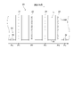
- FIG. 3 is a partial top view of the image forming apparatus in the vicinity of the image recording section
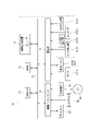
- FIG. It is a block diagram which shows the hardware constitutions of a control part.
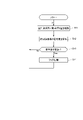
- FIG. 10 is a diagram showing processing executed by the first inference device;
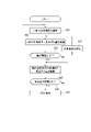
- FIG. 10 illustrates processing performed by a second reasoner;
- FIG. 1 is a diagram showing the configuration of an image forming apparatus 1.
- the image forming apparatus 1 records an image on the printing paper 9 by ejecting ink from a plurality of ejection heads 21 to 24 toward the printing paper 9 while conveying the printing paper 9, which is a long belt-shaped base material. It is an inkjet printing device.
- the substrate is not limited to the printing paper 9, and may be, for example, a resin film, a metal foil, or a glass substrate.
- the image forming apparatus 1 includes a transport mechanism 10, an image recording section 20, a measuring section 30, and a control section .
- the transport mechanism 10 transports the printing paper 9 in a predetermined transport direction.
- the conveying direction is parallel to the longitudinal direction of the printing paper 9 .
- the conveying mechanism 10 has an unwinding roller 11 , a plurality of conveying rollers 12 and a winding roller 13 .
- the print paper 9 is fed out from a feed roller 11 and transported along a transport path formed by a plurality of transport rollers 12 .
- Each conveying roller 12 guides the printing paper 9 to the downstream side of the conveying path by rotating around the rotation axis.
- the printed paper 9 after being transported is collected by the take-up roller 13 .
- a motor 15 is connected to each of the rotation shafts of the feed roller 11 and the take-up roller 13 .
- Each motor 15 is electrically connected to the controller 70 .
- Each motor 15 rotates the unwinding roller 11 and the winding roller 13 at a predetermined rotational speed based on the control signal transmitted by the control section 70 .
- the motor 15 may be connected to any one of the plurality of conveying rollers 12 .
- the printing paper 9 moves under the plurality of ejection heads 21 to 24 substantially parallel to the direction in which the plurality of ejection heads 21 to 24 are arranged. At this time, the recording surface of the printing paper 9 faces upward (toward the ejection heads 21 to 24). Also, the printing paper 9 is stretched over a plurality of transport rollers 12 while being tensioned. This suppresses slack and wrinkles in the printing paper 9 during transportation.
- the image recording unit 20 is a processing unit that ejects droplets of ink (hereinafter referred to as "ink droplets") onto the printing paper 9 conveyed by the conveying mechanism 10 .
- the image recording section 20 of this embodiment has four ejection heads 21 to 24 (ejection sections). The ejection heads 21 to 24 are arranged along the transport path of the printing paper 9 .
- FIG. 2 is a partial top view of the image forming apparatus 1 in the vicinity of the image recording section 20.
- FIG. Each of the ejection heads 21 to 24 covers the entire width of the printing paper 9 . 2, a plurality of nozzles 250 arranged in parallel with the width direction of the printing paper 9 are provided on the lower surface of each of the ejection heads 21-24.
- Each of the ejection heads 21 to 24 ejects K (black), C (cyan), M (magenta), and Y (yellow), which are color components of a multicolor image, from a plurality of nozzles 250 toward the upper surface of the printing paper 9. Ink droplets of each color are ejected.
- the ejection head 21 ejects K-color ink droplets onto the upper surface of the printing paper 9 at the ejection position P1 on the transport path.
- the ejection head 22 ejects C-color ink droplets onto the upper surface of the printing paper 9 at an ejection position P2 downstream of the ejection position P1.
- the ejection head 23 ejects M-color ink droplets onto the upper surface of the printing paper 9 at an ejection position P3 downstream of the ejection position P2.
- the ejection head 24 ejects Y-color ink droplets onto the upper surface of the printing paper 9 at an ejection position P4 downstream of the ejection position P3.
- the ejection positions P1 to P4 are arranged at regular intervals along the direction in which the printing paper 9 is transported.
- the four ejection heads 21 to 24 respectively record monochromatic images on the upper surface of the printing paper 9 by ejecting ink droplets.
- a multicolor image is formed on the upper surface of the printing paper 9 by superimposing the four monochromatic images. If the positions of the ink droplets ejected from the four ejection heads 21 to 24 on the printing paper 9 are deviated from each other in the transport direction, the image quality of the printed matter will be degraded. Therefore, the print quality of the image forming apparatus 1 can be improved by suppressing the error in the position of the monochromatic image on the printing paper 9 (hereinafter referred to as "misregistration amount") within an allowable range.
- the image forming apparatus 1 may include a drying processing section that dries ink ejected onto the recording surface of the printing paper 9 .
- the drying processing section is provided, for example, downstream of the ejection heads 21 to 24 in the transport direction.
- the drying unit dries the ink by, for example, blowing heated gas toward the printing paper 9 to evaporate the solvent in the ink adhering to the printing paper 9 .
- the drying processing section may dry the ink by heating with a heat roller or other methods such as light irradiation.
- the measurement unit 30 acquires measurement data of each measurement item by measuring a plurality of measurement items representing the state of the printing paper 9 .
- the measurement unit 30 specifically includes two torque detection units 31 , two edge position detection units 33 , two encoders 35 and two tension detection units 37 .
- a torque detection unit 31 is attached to each of the unwinding roller 11 and the winding roller 13 .
- Torque detector 31 detects the torque of the rotation shafts of feed roller 11 and take-up roller 13 .
- Torque detector 31 transmits a detection signal indicating the detected torque to controller 70 . It should be noted that it is not essential to detect the torques of both the feed roller 11 and the take-up roller 13, and only one of them may be detected. Also, the torque of any one of the plurality of conveying rollers 12 may be detected.
- the torque detected by the torque detector 31 is a measurement item that indicates the transport state of the printing paper 9 .
- the two edge position detection units 33 respectively detect the positions of the edges (ends in the width direction) 91 of the printing paper 9 in the width direction.
- the edge position detector 33 detects the edge 91 of the printing paper 9 at a detection position Pa upstream of the ejection position P1 on the transport path and a detection position Pb downstream of the ejection position P4 on the transport path. .
- the edge position detector 33 may detect the edge position of the printing paper 9 at a position different from the detection positions Pa and Pb.
- the position of the edge 91 detected by the edge position detection section 33 is a measurement item that indicates the transport state of the printing paper 9 .
- the edge position detection unit 33 is composed of, for example, a projector positioned above the edge 91 of the printing paper 9 and a line sensor positioned below the edge 91 .
- the projector emits parallel light downward.
- the line sensor has a plurality of light receiving elements arranged in the width direction. Outside the edge 91 of the printing paper 9, the light emitted from the light projector is incident on the light receiving element. On the other hand, inside the edge 91 of the printing paper 9, the light from the projector is blocked by the printing paper 9, so the light from the projector does not enter the light receiving element.
- the edge position detection unit 33 detects the position of the edge 91 of the printing paper 9 in the width direction based on the presence or absence of light detection in the plurality of light receiving elements.
- the two edge position detectors 33 intermittently detect the position of the edge 91 of the printing paper 9 at the detection positions Pa and Pb. The edge position detector 33 then transmits a detection signal indicating the position of the edge 91 to the controller 70 . Note that the edge position detector 33 may continuously detect the position of the edge 91 . It is not essential for the image forming apparatus 1 to have two edge position detection units 33, and it may have one or three or more.
- the two encoders 35 are provided for two transport rollers 12 (the transport rollers 121 in FIG. 1) selected from the plurality of transport rollers 12, respectively. Each encoder 35 detects the rotation of the transport roller 121 and transmits a continuous pulse signal synchronized with the rotation of the transport roller 121 to the controller 70 .
- the continuous pulse signal is measurement data that reflects changes over time in the conveying speed of the printing paper 9 conveyed by the plurality of conveying rollers 12 including the conveying roller 121 . It should be noted that it is not essential for the image forming apparatus 1 to have two encoders 35, and it may have one or three or more.
- the two tension detectors 37 are attached to two selected from the plurality of conveying rollers 12 (two conveying rollers 122 in FIG. 1).
- the tension detector 37 measures the force that the conveying roller 122 receives from the printing paper 9 .
- the tension detector 37 detects the tension applied to the printing paper 9 and outputs a detection signal indicating the detected tension to the controller 70 .
- the tension of the printing paper 9 is a measurement item that represents the transport state of the printing paper 9 . It should be noted that it is not essential that the tension of the two transport rollers 12 is detected, and the tension of one or more than three transport rollers 12 may be detected.
- FIG. 3 is a block diagram showing the hardware configuration of the control unit 70.
- the control unit 70 controls the operation of each unit in the image forming apparatus 1 .
- the control section 70 includes a processor 71 , a RAM 72 , an auxiliary storage device 73 , a device interface 74 and a communication section 75 .
- RAM 72 , auxiliary storage device 73 , device interface 74 , and communication section 75 are electrically connected to processor 71 via bus wiring 76 .
- the processor 71 is composed of, for example, a CPU or GPU.
- the RAM 72 is a readable/writable memory and stores various information processed by the processor 71 .
- the auxiliary storage device 73 is a non-transitory storage medium such as a hard disk drive.
- the auxiliary storage device 73 stores a program P.
- the device interface 74 is an intermediary device that mediates data exchange between an external device (peripheral device, etc.) and the control unit 70 .
- Control unit 70 is electrically connected to display 81 , input device 82 , and reader 83 via equipment interface 74 .
- the display 81 displays various information.
- the input device 82 is composed of a mouse, keyboard, or the like.
- the control unit 70 receives user input via the input device 82 .
- the display 81 may function as the input device 82 by configuring the display 81 with a touch panel.
- the reading device 83 reads information recorded on the recording medium 84 .
- the recording medium 84 is, for example, a non-transitory recording medium such as an optical disk, magnetic disk, magneto-optical disk, or memory card.
- the control unit 70 reads the program P from the recording medium 84 in advance via the reading device 83 and stores the program P in the auxiliary storage device 73 . Note that the control unit 70 may acquire the program P via a network.
- a user of the image forming apparatus 1 can input, for example, the type or amount of ink ejected from the plurality of ejection heads 21 to 24 of the image recording unit 20, the type, shape, thickness, etc. of the printing paper 9 via the input device 82.
- Enter information about The control unit 70 stores the input information in the RAM 72 or the auxiliary storage device 73 .
- the control unit 70 may acquire information related to various setting values and conditions via its own sensors or the like.
- the communication unit 75 includes the two motors 15 of the transport mechanism 10, the four ejection heads 21 to 24, the measurement unit 30 (two torque detection units 31, two edge position detection units 33, two encoders 35, two It is connected to the tension detector 37) so as to be capable of wired communication or wireless communication.
- the processor 71 temporarily stores the program P in the RAM 72 and performs arithmetic processing based on the stored program P.
- the control unit 70 controls the operation of each unit of the image forming apparatus 1 so that the printing paper 9 is conveyed and the ink is ejected onto the printing paper 9 in the image forming apparatus 1 .
- a misregistration amount is predicted in the conveying direction of the printing paper 9, which will be described later.
- the processor 71 functions as a first reasoner 711, a second reasoner 712, and a discharge controller 713 by operating based on the program P (see FIG. 1).
- the first reasoner 711 and the second reasoner 712 predict (infer) the misregistration amount based on the measurement data acquired by the measurement unit 30 .
- the first reasoner 711 and the second reasoner 712 have trained models obtained by machine learning of a supervised learning algorithm.
- a trained model is obtained by machine learning that infers the misregistration amount from the measurement data of each measurement item.
- the teacher data is composed of a set of measurement data for each measurement item acquired by the measurement unit 30 and an actual measurement value of the amount of misregistration.
- Algorithms for supervised learning include, for example, support vector machines, neural networks, linear models, and gradient boosting.
- the input of measurement data to the target model and the output of the amount of misregistration from the model are repeatedly executed, and the parameters of the model are adjusted so that the amount of misregistration output from the model approaches the measured value. be done. Finally, a trained model with adjusted parameters is generated.
- the measured value of the misregistration amount is obtained, for example, as follows. First, in the image forming apparatus 1, the ejection heads 21 to 24 print predetermined marks on the printing paper 9 transported by the transport mechanism 10, respectively. Then, by actually measuring the magnitude of the positional deviation of each mark printed on the printing paper 9, the misregistration amount is obtained. Also, while each mark is being printed, the measurement unit 30 collects measurement data for each measurement item. A set of the measured value of the misregistration amount acquired in this way and the measurement data of each measurement item corresponding to the measured value is used as teacher data.
- the learned model (first learned model) of the first inference device 711 is configured to receive as input measurement data of all measurement items (all measurement items measured by the measurement unit 30) and output misregistration amounts. be. Therefore, in the machine learning for obtaining the trained model of the first inference device 711, a set of measurement data (input) of all measurement items and actual measurement values (output) of the amount of misregistration is used as teacher data. . Also, the trained model (second trained model) of the second inference unit 712 is configured to receive the measurement data of some measurement items among all the measurement items as input and output the amount of misregistration. Therefore, in the machine learning for obtaining the trained model of the second reasoner 712, a set of measurement data (input) related to the combination of various measurement items and actual measurement values (output) of misregistration is used as teacher data. is used.
- the ejection control unit 713 controls the ejection of ink from the ejection heads 21-24. More specifically, the ejection of ink from the ejection heads 21 to 24 is controlled so as to offset the amount of misregistration inferred by the second reasoner 712 . For example, if the second inference device 712 infers that misregistration will occur between the ejection heads 21 and 22, the ejection control unit 713 sets the ejection timing of the ink from the ejection head 22 to the timing when it is inferred that there is no misregistration. Shift with respect to ejection timing. As a result, misregistration between the images formed by the ejection heads 21 and 22 can be suppressed.
- control unit 70 may control the transport speed of the printing paper 9 by the transport mechanism 10 so as to offset the amount of misregistration inferred by the second reasoner 712 .
- the portions of the printing paper 9 to which the ejection heads 21 to 24 should apply ink can pass through the ejection positions P1 to P4 at ideal times or times close to the ideal times. Therefore, even if the ejection control unit 713 does not correct the ejection timings from the ejection heads 21 to 24 based on the amount of misregistration, it is possible to suppress misregistration between the images formed by the ejection heads 21 to 24 .
- FIG. 4 is a diagram showing processing executed by the first inference unit 711. As shown in FIG. As shown in FIG. 4, the first reasoner 711 repeatedly executes the inference process S11 to the flag process S14 while the image forming apparatus 1 is printing.
- the first inference device 711 infers the misregistration amount (first misregistration amount) using all the measurement data acquired by the measurement unit 30 (inference processing S11).
- the first inference unit 711 calculates the degree of contribution of each measurement item to the output first misregistration amount (contribution degree calculation processing S12).
- the first reasoner 711 stores the calculated contribution of each measurement item in the storage unit (RAM 72 or auxiliary storage device 73).
- the degree of contribution is a value that indicates the weighting of each measurement item when calculating the estimated misregistration amount from the measurement data of a plurality of measurement items in the first trained model of the first inference device 711 .
- the contribution can be calculated based on the learned parameters of the first trained model. For the contribution, for example, a SHAP (SHApley Additive exPlanations) value can be used.
- SHAP SHApley Additive exPlanations
- the first inference unit 711 determines whether the degree of contribution calculated by the calculation process S12 has changed from the degree of contribution calculated last time (determination process S13). When the first inference unit 711 determines in the determination processing S13 that the contribution of at least some of all the measurement items has changed, the first inference unit 711 A flag indicating that the contribution of has changed is set (flag processing S14). After setting the flag, the first inference device 711 executes the inference processing S11 again. On the other hand, when the first inference unit 711 determines in the determination processing S13 that the contribution has not changed, the first inference unit 711 does not execute the flag processing S14 and executes the inference processing S11 again.
- the first inference unit 711 periodically executes the inference of the misregistration amount (first misregistration amount) using the measurement data of all measurement items and the calculation of the contribution of each measurement item. do. Also, when the degree of contribution fluctuates, a flag is appropriately set.
- FIG. 5 is a diagram showing the processing performed by the second reasoner 712. As shown in FIG. As shown in FIG. 5, the second inference unit 712 repeatedly executes the selection process S21 to the determination process S26 while the image forming apparatus 1 is printing.
- the second reasoner 712 selects some measurement items from all measurement items (selection processing S21). Some of the measurement items selected by the second reasoner 712 are used when the second reasoner 712 infers the amount of misregistration.
- the second inference unit 712 selects, for example, measurement items from the 1st place to the nth place (n is a natural number smaller than m) in descending order of contribution from all m (m is a natural number) measurement items. .
- the second inference unit 712 After selecting some of the measurement items in the selection process S21, the second inference unit 712 infers the misregistration amount (second misregistration amount) using the measurement data of the selected part of the measurement items (inference process S22). ). The second inference device 712 determines if the difference between the misregistration amount inferred by the inference processing S22 and the misregistration amount (first misregistration amount) inferred by the first inference device 711 in the inference processing S11 is equal to or less than a predetermined threshold. It is determined whether there is (determination processing S23).
- the second inference unit 712 determines in the determination processing S23 that the difference exceeds the threshold, the second inference unit 712 adds another measurement item to the currently selected measurement item (addition process S24).
- addition processing S24 the second inference device 712 selects measurement items to be added based on the contribution calculated by the first inference device 711 in the calculation processing S12. For example, the second inference unit 712 adds the measurement item with the largest contribution among the currently unselected measurement items in the addition process S24. After completing the additional processing S24, the second inference device 712 executes the inference processing S22 again.
- the second inference unit 712 repeatedly executes the inference processing S22 to the addition processing S24 until the difference in the misregistration amount becomes equal to or less than the predetermined threshold. This allows the second inference unit 712 to select some measurement items suitable for inferring the amount of misregistration from all measurement items.
- the second inference unit 712 performs exchange processing for exchanging some of the selected measurement items with some other measurement items according to a predetermined rule instead of the additional processing S24. may Then, in the inference processing S25, the second inference device 712 may infer the amount of misregistration using the measurement data of some measurement items selected after the exchange. Also, the second inference unit 712 may perform both the addition process S24 and the replacement process. Furthermore, the second inference unit 712 may alternately perform the addition process S24 and the replacement process.
- the second inference unit 712 determines in the determination processing S23 that the difference in the amount of misregistration is equal to or less than the threshold, the amount of misregistration is inferred using the measurement data of the part of measurement items currently selected. (Inference processing S25).
- the ejection control unit 713 described above determines the ejection timing of the ink from the nozzles 250 of the ejection heads 21 to 24 so as to offset the amount of misregistration inferred by the second reasoner 712 in the reasoning process S25. As a result, it is possible to suppress misregistration between the images formed by the ejection heads 21 to 24 .
- the second inference unit 712 determines whether the degree of contribution has changed (determination process S26). Specifically, in the determination process S26, the second inference unit 712 determines whether the flag in the flag process S14 (FIG. 4) is set. When the second inference unit 712 determines in the determination processing S26 that the flag is set, the second inference unit 712 removes the flag (flag removal processing S27). After removing the flag, the second reasoner 712 executes the selection process S21 again.
- the second inference unit 712 determines in the determination processing S26 that the flag is not set, it executes the inference processing S25 again. Therefore, when the degree of contribution does not change, the second inference unit 712 periodically and repeatedly infers the amount of misregistration.
- the first reasoner 711 infers the amount of misregistration using the measurement data of all measurement items. In this case, although the amount of misregistration can be inferred with high accuracy, the amount of computation for inference increases.
- the second reasoner 712 infers the amount of misregistration using the measurement data of some measurement items among all the measurement items. Therefore, the amount of computation performed by the second inference unit 712 can be made smaller than the amount of computation performed by the first inference unit 711 . Therefore, it is possible to shorten the time required for inferring the amount of misregistration.
- Some measurement items are selected based on the degree of contribution of each measurement item to the amount of misregistration inferred by the first inference device 711 . Therefore, even if the measurement data of some measurement items are used, the misregistration amount can be inferred with high accuracy.
- the measurement items measured by the measurement unit 30 are not limited to those described above.
- the measurement unit 30 may include a temperature sensor that detects temperatures inside and outside the image forming apparatus 1 and a humidity sensor that detects humidity inside and outside the image forming apparatus 1 . Then, temperature and humidity may each be included in the measurement items.
Landscapes
- Engineering & Computer Science (AREA)
- Quality & Reliability (AREA)
- Ink Jet (AREA)
- Handling Of Sheets (AREA)
- Controlling Rewinding, Feeding, Winding, Or Abnormalities Of Webs (AREA)
- Accessory Devices And Overall Control Thereof (AREA)
Abstract
Description
図1は、画像形成装置1の構成を示す図である。画像形成装置1は、長尺帯状の基材である印刷用紙9を搬送しつつ、複数の吐出ヘッド21~24から印刷用紙9へ向けてインクを吐出することにより、印刷用紙9に画像を記録するインクジェット方式の印刷装置である。なお、基材は、印刷用紙9に限定されるものではなく、例えば、樹脂製のフィルム、金属箔、または、ガラス製の基材などであってもよい。図1に示すように、画像形成装置1は、搬送機構10と、画像記録部20と、計測部30と、制御部70とを備えている。
図4は、第1推論器711が実行する処理を示す図である。図4に示すように、第1推論器711は、画像形成装置1において印刷が行われている間、推論処理S11からフラグ処理S14までを繰り返し実行する。
図5は、第2推論器712が実行する処理を示す図である。図5に示すように、第2推論器712は、画像形成装置1において印刷が行われている間、選択処理S21から判定処理S26までを繰り返し実行する。
以上、実施形態について説明してきたが、本発明は上記のようなものに限定されるものではなく、様々な変形が可能である。
9 印刷用紙
10 搬送機構
20 画像記録部
21,22 吐出ヘッド
23,24 吐出ヘッド
30 計測部
31 トルク検出部
33 エッジ位置検出部
35 エンコーダ
37 張力検出部
70 制御部
711 第1推論器
712 第2推論器
713 吐出制御部
Claims (5)
- 画像形成装置であって、
長尺帯状の基材を、所定の搬送経路に沿って前記基材の長手方向に搬送する搬送機構と、
前記搬送機構によって搬送される前記基材に第1インクを吐出する第1吐出部と、
前記第1吐出部よりも下流側に位置し、前記搬送機構によって搬送される前記基材に第2インクを吐出する第2吐出部と、
前記基材の状態に関する複数の計測項目毎に計測データを取得する計測部と、
前記複数の計測項目の計測データに基づいて、前記第1吐出部が形成する第1画像と、前記第2吐出部が形成する第2画像との間の見当ずれ量を推論する第1推論器と、
前記第1推論器が推論した前記見当ずれ量に対する計測項目毎の寄与度に基づいて、前記複数の計測項目から一部の計測項目を選択するとともに、選択した前記一部の計測項目の計測データを用いて前記見当ずれ量を推論する第2推論器と、
を備える、画像形成装置。 - 請求項1に記載の画像形成装置であって、
前記第2推論器は、前記第1推論器が推論する前記見当ずれ量と前記第2推論器が推論する前記見当ずれ量との誤差が所定の閾値以下となるように、前記複数の計測項目から前記一部の計測項目を選択する、画像形成装置。 - 請求項1または請求項2に記載の画像形成装置であって、
前記第2推論器は、前記寄与度の変動に応じて、前記複数の計測項目から一部の計測項目を再度選択し、再度選択した前記一部の計測項目の計測データを用いて前記見当ずれ量を推論する、画像形成装置。 - 請求項1から請求項3のいずれか1項に記載の画像形成装置であって、
前記第2推論器が推論した前記見当ずれ量に基づいて、前記第2吐出部からのインクの吐出を制御する吐出制御部、
をさらに備える、画像形成装置。 - 画像形成方法であって、
a) 長尺帯状の基材を、所定の搬送経路に沿って前記基材の長手方向に搬送する工程と、
b) 前記工程a)によって搬送される前記基材に第1インクを吐出する工程と、
c) 前記工程b)にて前記第1インクが吐出される位置よりも下流側で、前記工程a)によって搬送される前記基材に第2インクを吐出する工程と、
d) 前記基材の状態に関する複数の計測項目毎に計測データを取得する工程と、
e) 前記複数の計測項目の計測データに基づいて、前記工程b)により前記基材に形成される第1画像と、前記工程c)により前記基材に形成される第2画像との間の見当ずれ量を推論する工程と、
f) 前記工程e)によって推論された前記見当ずれ量に対する計測項目毎の寄与度に基づいて、前記複数の計測項目から一部の計測項目を選択する工程と、
g) 前記工程f)によって選択された前記一部の計測項目の計測データを用いて前記見当ずれ量を推論する工程と、
を含む、画像形成方法。
Priority Applications (2)
| Application Number | Priority Date | Filing Date | Title |
|---|---|---|---|
| EP21923101.6A EP4286310A4 (en) | 2021-01-29 | 2021-11-24 | IMAGE FORMING DEVICE AND METHOD |
| US18/274,333 US12420546B2 (en) | 2021-01-29 | 2021-11-24 | Image formation apparatus and method of forming an image |
Applications Claiming Priority (2)
| Application Number | Priority Date | Filing Date | Title |
|---|---|---|---|
| JP2021013089A JP7428671B2 (ja) | 2021-01-29 | 2021-01-29 | 画像形成装置および画像形成方法 |
| JP2021-013089 | 2021-01-29 |
Publications (1)
| Publication Number | Publication Date |
|---|---|
| WO2022163096A1 true WO2022163096A1 (ja) | 2022-08-04 |
Family
ID=82653180
Family Applications (1)
| Application Number | Title | Priority Date | Filing Date |
|---|---|---|---|
| PCT/JP2021/043024 Ceased WO2022163096A1 (ja) | 2021-01-29 | 2021-11-24 | 画像形成装置および画像形成方法 |
Country Status (4)
| Country | Link |
|---|---|
| US (1) | US12420546B2 (ja) |
| EP (1) | EP4286310A4 (ja) |
| JP (1) | JP7428671B2 (ja) |
| WO (1) | WO2022163096A1 (ja) |
Cited By (1)
| Publication number | Priority date | Publication date | Assignee | Title |
|---|---|---|---|---|
| TWI876721B (zh) * | 2023-11-30 | 2025-03-11 | 財團法人金屬工業研究發展中心 | 串級控制捲繞系統 |
Citations (3)
| Publication number | Priority date | Publication date | Assignee | Title |
|---|---|---|---|---|
| JP2018016412A (ja) | 2016-07-25 | 2018-02-01 | 株式会社Screenホールディングス | 基材処理装置および蛇行予測方法 |
| JP2020045234A (ja) * | 2018-09-20 | 2020-03-26 | 株式会社Screenホールディングス | 基材処理装置および検出方法 |
| JP2020164321A (ja) * | 2019-03-29 | 2020-10-08 | 株式会社Screenホールディングス | 基材処理装置および基材処理方法 |
Family Cites Families (3)
| Publication number | Priority date | Publication date | Assignee | Title |
|---|---|---|---|---|
| US9213287B1 (en) | 2014-07-31 | 2015-12-15 | Eastman Kodak Company | Document registration using registration error model |
| DE102019208257A1 (de) | 2018-07-03 | 2020-01-09 | Heidelberger Druckmaschinen Ag | Druckqualitätsanalyse mit neuronalen Netzen |
| JP7730728B2 (ja) * | 2021-11-10 | 2025-08-28 | エスアイアイ・プリンテック株式会社 | 噴射パラメータ生成システム、噴射パラメータ生成方法および噴射パラメータ生成プログラム |
-
2021
- 2021-01-29 JP JP2021013089A patent/JP7428671B2/ja active Active
- 2021-11-24 US US18/274,333 patent/US12420546B2/en active Active
- 2021-11-24 EP EP21923101.6A patent/EP4286310A4/en active Pending
- 2021-11-24 WO PCT/JP2021/043024 patent/WO2022163096A1/ja not_active Ceased
Patent Citations (3)
| Publication number | Priority date | Publication date | Assignee | Title |
|---|---|---|---|---|
| JP2018016412A (ja) | 2016-07-25 | 2018-02-01 | 株式会社Screenホールディングス | 基材処理装置および蛇行予測方法 |
| JP2020045234A (ja) * | 2018-09-20 | 2020-03-26 | 株式会社Screenホールディングス | 基材処理装置および検出方法 |
| JP2020164321A (ja) * | 2019-03-29 | 2020-10-08 | 株式会社Screenホールディングス | 基材処理装置および基材処理方法 |
Non-Patent Citations (1)
| Title |
|---|
| See also references of EP4286310A4 |
Cited By (1)
| Publication number | Priority date | Publication date | Assignee | Title |
|---|---|---|---|---|
| TWI876721B (zh) * | 2023-11-30 | 2025-03-11 | 財團法人金屬工業研究發展中心 | 串級控制捲繞系統 |
Also Published As
| Publication number | Publication date |
|---|---|
| EP4286310A4 (en) | 2024-12-25 |
| JP2022116753A (ja) | 2022-08-10 |
| US20250144946A1 (en) | 2025-05-08 |
| US12420546B2 (en) | 2025-09-23 |
| JP7428671B2 (ja) | 2024-02-06 |
| EP4286310A1 (en) | 2023-12-06 |
Similar Documents
| Publication | Publication Date | Title |
|---|---|---|
| JP6468805B2 (ja) | 画像記録装置および画像記録方法 | |
| JP6715120B2 (ja) | 基材処理装置および蛇行予測方法 | |
| JP2023113742A (ja) | 基材処理装置および基材処理方法 | |
| JP6949627B2 (ja) | 基材処理装置および検出方法 | |
| CN108621589B (zh) | 基材处理装置及检测方法 | |
| JP2021146510A (ja) | 学習方法、制御方法、および印刷装置 | |
| JP7449732B2 (ja) | 異常検知方法および搬送装置 | |
| CN109551904B (zh) | 基材处理装置以及检测方法 | |
| WO2023068026A1 (ja) | 印刷装置および管理方法 | |
| WO2022163096A1 (ja) | 画像形成装置および画像形成方法 | |
| JP2022122676A (ja) | 搬送装置、処理装置、搬送方法、および処理方法 | |
| JP7198020B2 (ja) | 基材処理装置および検出方法 | |
| JP2021147226A (ja) | 調整方法および印刷装置 | |
| JP7550667B2 (ja) | 基材処理方法 | |
| JP7221763B2 (ja) | 基材処理方法 | |
| JP7460517B2 (ja) | 印刷装置および管理方法 | |
| TWI852122B (zh) | 印刷裝置及印刷方法 | |
| JP7126976B2 (ja) | 基材処理装置および検出方法 | |
| JP2023034928A (ja) | 検出方法、学習方法、推定方法、印刷方法、および検出装置 | |
| JP2021147112A (ja) | 搬送処理方法 | |
| WO2023166812A1 (ja) | 推定方法、制御方法、および装置 |
Legal Events
| Date | Code | Title | Description |
|---|---|---|---|
| 121 | Ep: the epo has been informed by wipo that ep was designated in this application |
Ref document number: 21923101 Country of ref document: EP Kind code of ref document: A1 |
|
| WWE | Wipo information: entry into national phase |
Ref document number: 2021923101 Country of ref document: EP |
|
| NENP | Non-entry into the national phase |
Ref country code: DE |
|
| ENP | Entry into the national phase |
Ref document number: 2021923101 Country of ref document: EP Effective date: 20230829 |
|
| WWP | Wipo information: published in national office |
Ref document number: 18274333 Country of ref document: US |
|
| WWG | Wipo information: grant in national office |
Ref document number: 18274333 Country of ref document: US |