WO2022163295A1 - 染色システム - Google Patents
染色システム Download PDFInfo
- Publication number
- WO2022163295A1 WO2022163295A1 PCT/JP2021/048849 JP2021048849W WO2022163295A1 WO 2022163295 A1 WO2022163295 A1 WO 2022163295A1 JP 2021048849 W JP2021048849 W JP 2021048849W WO 2022163295 A1 WO2022163295 A1 WO 2022163295A1
- Authority
- WO
- WIPO (PCT)
- Prior art keywords
- dye
- resin body
- laser
- transport
- dyeing
- Prior art date
- Legal status (The legal status is an assumption and is not a legal conclusion. Google has not performed a legal analysis and makes no representation as to the accuracy of the status listed.)
- Ceased
Links
Images

Classifications
-
- D—TEXTILES; PAPER
- D06—TREATMENT OF TEXTILES OR THE LIKE; LAUNDERING; FLEXIBLE MATERIALS NOT OTHERWISE PROVIDED FOR
- D06P—DYEING OR PRINTING TEXTILES; DYEING LEATHER, FURS OR SOLID MACROMOLECULAR SUBSTANCES IN ANY FORM
- D06P5/00—Other features in dyeing or printing textiles, or dyeing leather, furs, or solid macromolecular substances in any form
- D06P5/20—Physical treatments affecting dyeing, e.g. ultrasonic or electric
- D06P5/2066—Thermic treatments of textile materials
- D06P5/2072—Thermic treatments of textile materials before dyeing
-
- B—PERFORMING OPERATIONS; TRANSPORTING
- B29—WORKING OF PLASTICS; WORKING OF SUBSTANCES IN A PLASTIC STATE IN GENERAL
- B29D—PRODUCING PARTICULAR ARTICLES FROM PLASTICS OR FROM SUBSTANCES IN A PLASTIC STATE
- B29D11/00—Producing optical elements, e.g. lenses or prisms
- B29D11/00009—Production of simple or compound lenses
-
- B—PERFORMING OPERATIONS; TRANSPORTING
- B29—WORKING OF PLASTICS; WORKING OF SUBSTANCES IN A PLASTIC STATE IN GENERAL
- B29D—PRODUCING PARTICULAR ARTICLES FROM PLASTICS OR FROM SUBSTANCES IN A PLASTIC STATE
- B29D11/00—Producing optical elements, e.g. lenses or prisms
- B29D11/00009—Production of simple or compound lenses
- B29D11/00423—Plants for the production of simple or compound lenses
-
- B—PERFORMING OPERATIONS; TRANSPORTING
- B29—WORKING OF PLASTICS; WORKING OF SUBSTANCES IN A PLASTIC STATE IN GENERAL
- B29D—PRODUCING PARTICULAR ARTICLES FROM PLASTICS OR FROM SUBSTANCES IN A PLASTIC STATE
- B29D11/00—Producing optical elements, e.g. lenses or prisms
- B29D11/00865—Applying coatings; tinting; colouring
- B29D11/00894—Applying coatings; tinting; colouring colouring or tinting
- B29D11/00903—Applying coatings; tinting; colouring colouring or tinting on the surface
-
- B—PERFORMING OPERATIONS; TRANSPORTING
- B29—WORKING OF PLASTICS; WORKING OF SUBSTANCES IN A PLASTIC STATE IN GENERAL
- B29D—PRODUCING PARTICULAR ARTICLES FROM PLASTICS OR FROM SUBSTANCES IN A PLASTIC STATE
- B29D11/00—Producing optical elements, e.g. lenses or prisms
- B29D11/00951—Measuring, controlling or regulating
-
- B—PERFORMING OPERATIONS; TRANSPORTING
- B29—WORKING OF PLASTICS; WORKING OF SUBSTANCES IN A PLASTIC STATE IN GENERAL
- B29D—PRODUCING PARTICULAR ARTICLES FROM PLASTICS OR FROM SUBSTANCES IN A PLASTIC STATE
- B29D11/00—Producing optical elements, e.g. lenses or prisms
- B29D11/00951—Measuring, controlling or regulating
- B29D11/0098—Inspecting lenses
-
- D—TEXTILES; PAPER
- D06—TREATMENT OF TEXTILES OR THE LIKE; LAUNDERING; FLEXIBLE MATERIALS NOT OTHERWISE PROVIDED FOR
- D06P—DYEING OR PRINTING TEXTILES; DYEING LEATHER, FURS OR SOLID MACROMOLECULAR SUBSTANCES IN ANY FORM
- D06P5/00—Other features in dyeing or printing textiles, or dyeing leather, furs, or solid macromolecular substances in any form
- D06P5/003—Transfer printing
-
- D—TEXTILES; PAPER
- D06—TREATMENT OF TEXTILES OR THE LIKE; LAUNDERING; FLEXIBLE MATERIALS NOT OTHERWISE PROVIDED FOR
- D06P—DYEING OR PRINTING TEXTILES; DYEING LEATHER, FURS OR SOLID MACROMOLECULAR SUBSTANCES IN ANY FORM
- D06P5/00—Other features in dyeing or printing textiles, or dyeing leather, furs, or solid macromolecular substances in any form
- D06P5/003—Transfer printing
- D06P5/004—Transfer printing using subliming dyes
-
- D—TEXTILES; PAPER
- D06—TREATMENT OF TEXTILES OR THE LIKE; LAUNDERING; FLEXIBLE MATERIALS NOT OTHERWISE PROVIDED FOR
- D06P—DYEING OR PRINTING TEXTILES; DYEING LEATHER, FURS OR SOLID MACROMOLECULAR SUBSTANCES IN ANY FORM
- D06P5/00—Other features in dyeing or printing textiles, or dyeing leather, furs, or solid macromolecular substances in any form
- D06P5/20—Physical treatments affecting dyeing, e.g. ultrasonic or electric
- D06P5/2005—Treatments with alpha, beta, gamma or other rays, e.g. stimulated rays
-
- D—TEXTILES; PAPER
- D06—TREATMENT OF TEXTILES OR THE LIKE; LAUNDERING; FLEXIBLE MATERIALS NOT OTHERWISE PROVIDED FOR
- D06P—DYEING OR PRINTING TEXTILES; DYEING LEATHER, FURS OR SOLID MACROMOLECULAR SUBSTANCES IN ANY FORM
- D06P5/00—Other features in dyeing or printing textiles, or dyeing leather, furs, or solid macromolecular substances in any form
- D06P5/20—Physical treatments affecting dyeing, e.g. ultrasonic or electric
- D06P5/2011—Application of vibrations, pulses or waves for non-thermic purposes
-
- D—TEXTILES; PAPER
- D06—TREATMENT OF TEXTILES OR THE LIKE; LAUNDERING; FLEXIBLE MATERIALS NOT OTHERWISE PROVIDED FOR
- D06P—DYEING OR PRINTING TEXTILES; DYEING LEATHER, FURS OR SOLID MACROMOLECULAR SUBSTANCES IN ANY FORM
- D06P5/00—Other features in dyeing or printing textiles, or dyeing leather, furs, or solid macromolecular substances in any form
- D06P5/20—Physical treatments affecting dyeing, e.g. ultrasonic or electric
- D06P5/2066—Thermic treatments of textile materials
- D06P5/2077—Thermic treatments of textile materials after dyeing
Definitions
- the present disclosure relates to a dyeing system for dyeing a resin body.
- a technique has been proposed in which a dye is transferred to the surface of a resin body and the resin body with the dye attached is heated to dye the resin body.
- a sublimation dye is applied (printed) onto a substrate by an inkjet printer.
- the dye is transferred to the resin body by sublimating the sublimable dye applied to the substrate while the resin body and the substrate are arranged in a vacuum without being in contact with each other.
- the surface of the resin body is heated and the dye is fixed.
- the dyeing method described in Patent Document 2 the dye is fixed to the resin body by heating the resin body in an oven.
- the time required for the fixing process is likely to be shortened compared to the case of using an oven.
- an oven for example, regardless of the type of base material of the resin body, the color to be dyed, etc., there is an advantage that the dye can be appropriately fixed to the resin body. In the conventional method, only one of the laser beam and the oven is used to fix the dye on the resin body, so it is difficult to sufficiently improve the efficiency of the dyeing process.
- a typical object of the present disclosure is to provide a dyeing system capable of more appropriately dyeing a resin body.
- a dyeing system provided by a typical embodiment of the present disclosure is a dyeing system for dyeing a resin body, comprising a transport device that transports a transport unit containing a resin body, and a transport unit transported by the transport device.
- a laser fixing device that fixes the dye adhered to the surface of the resin body to the resin body by heating the resin body by heating the above
- An oven fixing device for fixing the dye attached to the surface of the resin body to the resin body, and the conveying unit including the resin body to which the transfer of the dye by the transfer device is completed and the dye is fixed by the laser fixing device. and an oven transport path for transporting the transport unit containing the resin body on which the transfer of the dye by the transfer device is completed and the dye is fixed by the oven fixing device.
- the resin body is dyed more appropriately.
- the dyeing system exemplified in the present disclosure includes a transport device, a transfer device, a laser fixing device, an oven fixing device, a laser transport path, and an oven transport path.
- the transport device transports a transport unit containing a resin body.
- the transfer device transfers the dye to the resin body in a state in which the substrate to which the dye is adhered faces the resin body of the transport unit transported by the transport device.
- the laser fixing device irradiates and heats the surface of the resin body onto which the dye has been transferred by the transfer device with a laser beam, thereby fixing the dye attached to the surface of the resin body to the resin body.
- the oven fixing device heats the entire resin body to which the dye has been transferred by the transfer device, thereby fixing the dye attached to the surface of the resin body to the resin body.
- a conveying unit containing a resin body on which the transfer of the dye by the transfer device is completed and the dye is fixed by the laser fixing device is conveyed to the laser conveying path.
- a transport unit containing a resin body on which the transfer of the dye by the transfer device is completed and the dye is fixed by the oven fixing device is transported to the oven transport path.
- the conveying unit is conveyed from the transfer device to either the laser fixing device or the oven fixing device via the laser conveying path or the oven conveying path. That is, the dyeing system of the present disclosure can perform the fixing process with either a laser fixing device or an oven fixing device. Therefore, it is easier to improve the efficiency of the dyeing process than when only one of the laser fixing device and the oven fixing device is used.
- the dyeing system may further include a printing device.
- a printing device prints the dye onto the substrate.
- the dye is transferred and fixed to the resin body from the dye-bearing substrate in which at least one of the amount, concentration, distribution, etc. of the dye is appropriately adjusted by the printing apparatus. Therefore, the dyeing quality of the resin body is appropriately improved.
- a transfer method for transferring the dye to the resin body sublimation of the sublimation dye printed on the substrate is performed in a state in which the resin body and the dye-attached substrate face each other without contact in a vacuum.
- a vapor-phase transfer method for transferring a dye to a resin body it is also possible to change the transfer method.
- the dye may be transferred to the resin body while the dyed substrate is in contact with the resin body.
- the conveying device may automatically convey the conveying unit to the laser fixing device through the laser conveying path.
- the operator does not need to personally transport the transport unit from the transfer device to the laser fixing device. Therefore, the efficiency of the dyeing process is further improved.
- the conveying device may automatically convey the conveying unit to the oven fixing device through the oven conveying path.
- the operator does not need to personally transport the transport unit from the transfer device to the oven fixing device. Therefore, the efficiency of the dyeing process is further improved.
- At least one of the laser transport path and the oven transport path may be provided in the transport device. That is, the transport device may include at least one of the laser transport path and the oven transport path. In this case, the transport device may comprise a laser transport path and an oven transport path. The transport device may also include a laser transport path. The transport device may also include an oven transport path. With such a configuration, the transport unit is properly transported on the transport path of the transport device. Also, the method of transporting the transport unit can be appropriately selected from, for example, a method of transporting by a belt conveyor or the like, a method of transporting by a robot arm or the like.
- the dyeing system may further include a sorting section that sorts the transport unit for which the transfer of the dye by the transfer device is completed to either the laser transport path or the oven transport path. In this case, even if the operator does not sort the transport destinations of the transport units, the transport units are sorted to either the laser transport path or the oven transport path. Therefore, the efficiency of the dyeing process is further improved.
- the staining system may further comprise a controller.
- the control section may acquire the conditions of the dyeing process for each transport unit, and sort the transport units into either the laser transport path or the oven transport path according to the acquired conditions.
- each transport unit is appropriately distributed to an appropriate transport path according to the conditions of the dyeing process, out of the laser transport path and the oven transport path. Therefore, the efficiency of the dyeing process is further improved.
- control unit may determine whether the transport unit is suitable for laser fixing or oven fixing according to the dyeing process conditions acquired for each transport unit, and output the determination result.
- the operator can appropriately distribute the transport units to any of the transport paths based on the output determination result.
- At least one of, for example, display on a display unit, printing on paper, data transfer, and the like can be adopted as a method for outputting the determination result.
- the controller controls the conveying unit according to the condition of whether or not the resin body contained in the conveying unit and at least one of the colors to be dyed on the resin body are suitable for fixing the dye by the laser fixing device. You can distribute. That is, when at least one of the resin body contained in the transport unit and the color to be dyed is suitable for laser fixing, the control unit may distribute the transport unit to the laser transport path. The controller may sort the transport unit to the oven transport path when at least one of the resin body contained in the transport unit and the color to be dyed is not suitable for laser fixing.
- the laser fixing device tends to shorten the time required for the fixing process.
- the resin body it may be impossible or difficult to fix the dye with the laser fixing device.
- the color to be dyed on the resin body for example, at least one of the type and density of the color to be dyed
- it may be impossible or difficult to fix the dye by the laser fixing device in general, when the density of the color to be dyed on the resin body is high, fixing the dye by the laser fixing device tends to be more difficult than when the density is low.
- the oven fixing device since the temperature of the resin body gradually rises over a long period of time, it is difficult for a temperature difference to occur at each part of the resin body.
- the oven fixing device it is easy to appropriately fix the dye onto the resin body. Moreover, the possibility that the resin body will be damaged due to the temperature difference is also reduced.
- the transport units are sorted according to whether or not the resin bodies are suitable for laser fixing, the resin bodies suitable for laser fixing are subjected to the fixing process in a short time by the laser. On the other hand, resin bodies that are not suitable for laser fixing are appropriately subjected to the fixing process in an oven. Therefore, the efficiency of the dyeing process is properly improved.
- control unit can determine whether or not the dye is suitable for fixing by the laser fixing device based on various conditions. For example, the controller may determine whether the type of base material of the resin body is suitable for laser fixing. Also, the control unit may determine whether or not the shape of the resin body is suitable for laser fixing. The controller may determine whether or not the density of the color to be dyed on the resin body is suitable for laser fixation. The controller may determine whether or not the resin body is suitable for laser fixing based on a plurality of conditions (for example, the type and shape of the base material).
- the control unit may distribute the transport units according to whether the time required to execute the fixing process by the laser fixing device is equal to or less than the threshold. That is, when the time required for laser fixing of the resin body is equal to or less than the threshold value, the control section may sort the transport unit to the laser transport path. When the time required for laser fixing of the resin body is longer than the threshold value, the control section may sort the transport unit to the oven transport path. If the time required for the fixing process (laser fixing) by the laser fixing device increases, the number of transport units that are in a standby state before laser fixing increases, and the time required for the entire dyeing process may increase. On the other hand, by allocating the resin bodies for which the time required for laser fixing is longer than the threshold value to the oven transport path, the number of transport units waiting for laser fixing is less likely to increase. Therefore, a plurality of resin bodies are dyed more efficiently.
- the control unit may distribute the transport units according to the operating state of the laser fixing device. In this case, it becomes difficult to increase the number of conveying units that are on standby for laser fixing. Therefore, a plurality of resin bodies are dyed more efficiently.
- a specific method for allocating the transport units according to the operating state of the laser fixing device can be selected as appropriate.
- the controller may sort the transport unit to the oven transport path when the laser fixing device is in operation. Further, the control unit may acquire the waiting time until the laser fixing process is performed by the laser fixing device as information on the operating state of the laser fixing process. In this case, if the waiting time until the laser fixing process is performed is equal to or less than the threshold, the control unit sorts the conveying unit to the laser conveying path, and if the waiting time becomes longer than the threshold, the control unit The units may be distributed to the oven transport path. Further, the control section may sort the transport units according to whether the number of transport units waiting for laser fixing is equal to or greater than a threshold value.
- the oven fixing device collectively performs the fixing process for a plurality of resin bodies, which are larger than the number of units (for example, a pair of spectacle lenses) to which the laser fixing device can fix the dye in one fixing process. It may be executable. In this case, even if the fixing process by the oven fixing device takes a long time, the entire dyeing process proceeds smoothly by collectively performing the oven fixing on the resin bodies of the plurality of units.
- the control unit When the number of units on standby for the fixing process by the oven fixing device reaches a predetermined number, the control unit performs the fixing process by the oven fixing device on the resin bodies of the plurality of units on standby. may be started. In this case, the oven fixing to the resin bodies of the plurality of units is automatically performed more efficiently.
- control section may perform a notification operation to the operator when the number of units in a standby state for the fixing process by the oven fixing device reaches a predetermined number. In this case, the operator can appropriately grasp the timing of starting the fixing process by the oven fixing device from the notification.
- the dyeing system may be equipped with a reading unit that reads information about the transport unit.
- the control unit may acquire the conditions of the dyeing process for each transport unit based on the information read by the reading unit, and control the driving of the sorting unit according to the acquired conditions.
- the conditions for the dyeing process are appropriately acquired for each transport unit, and then the transport unit is assigned to either the laser transport path or the oven transport path. Therefore, a plurality of resin bodies are automatically and appropriately dyed.
- the reading unit may include an identifier reading unit that reads an identifier provided for each transport unit.
- the control unit may acquire the dyeing condition of the transport unit corresponding to the identifier read by the identifier reading unit from a database that stores the dyeing process conditions (dyeing conditions) for each transport unit. In this case, for example, even if the order of the plurality of transport units is changed, the dyeing conditions of each transport unit are properly grasped by the control unit.
- the identifier may be provided, for example, on a dyeing tray on which the resin body is placed, or may be provided on a substrate used in the transfer process.
- the reading unit may include a tag reading unit that reads information from a writable tag provided on the transport unit.
- the controller may acquire the staining conditions included in the information read by the tag reader. In this case, by storing the dyeing conditions in the tag in advance, the dyeing conditions of each transport unit can be properly grasped by the control unit even when the order of the transport units changes, for example.
- the dyeing system may further include a color information measuring instrument that measures color information of the resin body to which the dye is fixed.
- the color information measuring instrument may measure color information of both the resin body to which the dye is fixed by the laser fixing device and the resin body to which the dye is fixed by the oven fixing device. In this case, it is possible to use the measurement result of the color information by the color information measuring instrument for checking or improving the dyeing quality, for example. Further, the color information of both the laser-fixed resin body and the oven-fixed resin body are measured by a common color information measuring instrument. Therefore, the color information of the resin body can be appropriately measured while preventing the dyeing system from becoming complicated.
- the controller may execute the ejection amount determination step, the result color information acquisition step, and the correction step.
- the control unit determines, according to the determination procedure, the amount of dye to be ejected onto the substrate by the printing device in order to dye the resin body with the color to be dyed (planned color).
- the control unit uses the ejection amount of dye determined in the ejection amount determination step, so that the resin body actually dyed by the printing device, the transfer device, and the dye fixing device: Result color information, which is color information measured by the color information measuring instrument, is obtained.
- the controller corrects the ejection amount of the dye determined in the ejection amount determination step based on the resulting color information and the planned color, thereby correcting the color of the resin body to be dyed in the subsequent dyeing process. , closer to the intended color.
- the ejection amount of the dye printed on the substrate is corrected in order to dye the target color, so that the color of the actually dyed resin body appropriately approaches the target color.
- control unit may execute the pass/fail determination step and the error output step.
- pass/fail determination step the control unit determines whether or not the difference between the planned color and the result color information measured for the actually dyed resin body is within a threshold value.
- error output step the control unit outputs an error when the difference between the planned color and the resulting color information is not within the threshold value and the planned color and the resulting color are significantly different. In this case, the resin bodies for which the actually performed dyeing is of poor quality are appropriately excluded.
- FIG. 1 is a block diagram showing the system configuration of a staining system 1;
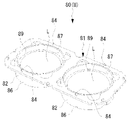
- FIG. It is the perspective view which looked at the dyeing
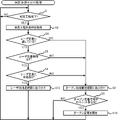
- 4 is a flowchart of a resin body sorting process executed by the dyeing system 1;
- the dyeing system 1 automatically and continuously dyes resin bodies.
- the resin body to be dyed is a plastic lens L (see FIG. 2, etc.) used for spectacles.
- the techniques exemplified in the present disclosure can also be applied when dyeing a resin body other than the lens L.
- various resin bodies such as goggles, mobile phone covers, light covers, accessories, toys, films (e.g., thickness of 400 ⁇ m or less), plate materials (e.g., thickness of 400 ⁇ m or more), etc. It is also possible to apply at least part of the techniques exemplified in the disclosure.
- the resin body to be dyed also includes a resin body attached to a member different from the resin body (for example, wood or glass). Further, the dyeing system 1 of the present embodiment dyes a plurality of resin bodies while continuously conveying them. However, at least a part of the technique illustrated in the present disclosure can also be adopted for a dyeing system that conveys and dyes resin bodies one by one.
- the dyeing system 1 of this embodiment includes a conveying device 10, a printing device 30, a transfer device 40, a laser fixing device 50A, an oven fixing device 50B, a color information measuring device 60, and a control device . Further, the dyeing system 1 of the present embodiment includes a laser transport path 15A, an oven transport path 15B, a sorting section 5, and an oven standby position 8.
- FIG. 1 A system configuration of a staining system 1 of the present embodiment will be schematically described with reference to FIG.
- the dyeing system 1 of this embodiment includes a conveying device 10, a printing device 30, a transfer device 40, a laser fixing device 50A, an oven fixing device 50B, a color information measuring device 60, and a control device . Further, the dyeing system 1 of the present embodiment includes a laser transport path 15A, an oven transport path 15B, a sorting section 5, and an oven standby position 8.
- FIG. 1 A system configuration of a staining system 1 of the present embodiment will be schematically described with reference to FIG.
- the transport device 10 transports the transport unit U (see FIG. 2) to each device in the dyeing system 1 continuously.
- the transport unit U is a unit transported by the transport device 10 .
- the transport unit U of the present embodiment includes a dyeing tray 80 (see FIG. 2) and a lens L placed on the dyeing tray 80 .
- the transport unit U may include a sheet-like substrate (dye-coated substrate) having a dye adhered to its surface.
- the transport device 10 of the present embodiment includes a belt conveyor that transports the transport unit U along the transport path.
- the transport device 10 may include a robot arm or the like that grips and transports the transport unit U.
- the printing device 30 prints a dye on a sheet-like substrate.
- the substrate is paper or a metallic (aluminum in this embodiment) film of moderate hardness.
- other materials such as glass plates, heat-resistant resins, and ceramics for the material of the substrate.
- the substrate and the lens L are separated and opposed to each other in a vacuum (including a substantially vacuum) environment. In this state, the dye on the substrate is heated, so that the dye is transferred (evaporated) onto the surface of the lens L (the dyeing method in this embodiment is referred to as a vapor-phase transfer dyeing method).
- the printing device 30 is an inkjet printer that prints ink containing a sublimation dye on a substrate.
- the printing device 30 performs printing based on print data created by a control device 70, which is an information processing device (in this embodiment, a personal computer (hereinafter referred to as “PC”)). Appropriate amount of ink (dye) adheres, making it easy to prepare a substrate with dye for gradation dyeing.
- PC personal computer
- the printing device may be a laser printer.
- the toner may contain a sublimation dye.
- the dye may be applied to the substrate by a dispenser (liquid metered application device), a roller, or the like.
- the transfer device 40 transfers the dye from the substrate to the lens L with the dye adhering to the substrate facing the lens L.
- the dye is transferred from the substrate to the lens L by the vapor phase transfer method.
- the method of transferring the dye to the lens L can also be changed.
- the dye may be transferred from the substrate to the lens L while the dye on the substrate and the lens L are in contact.
- the laser fixing device 50A fixes the dye adhering to the surface of the lens L to the lens L by irradiating the surface of the lens L onto which the dye has been transferred by the transfer device 40 with a laser beam and heating it.
- the laser fixing device 50A of this embodiment includes a laser light source and a scanner.
- the laser light source emits laser light.
- the scanner scans laser light emitted from a laser light source.
- the laser light is two-dimensionally scanned on the surface of the lens L by a scanner, so that the surface of the lens L is heated.
- the laser fixing device 50A of this embodiment performs one fixing step for each transport unit U (that is, for each lens L or a pair of lenses L included in one transport unit U).
- the laser fixing device 50A can fix the dye on the lens L in a shorter time than the oven fixing device 50B.
- the laser fixing device 50A determines the type of base material of the lens L to be dyed, the shape of the lens L, and/or the like, depending on at least one of the laser light irradiation conditions (for example, the fixing process by irradiating the laser light). At least one of the required time and laser light output control conditions, etc.) is changed.
- the type and shape of the base material of the lens L which is a resin body, it may be difficult to properly fix the dye onto the lens L with laser light.
- the oven fixing device 50B fixes the dye adhering to the surface of the lens L to the lens L by heating the entire lens L onto which the dye has been transferred by the transfer device 40 .
- the oven fixing device 50B of the present embodiment heats the entire lens L by heating the entire heating chamber (gas in the heating chamber and the lens L) while the lens L is placed inside the heating chamber. .
- the oven fixing device 50B since the temperature of the lens L gradually rises over a long period of time, it is difficult for a temperature difference to occur at each part of the lens L. Therefore, according to the oven fixing device 50B, the dye is easily fixed to the lens L appropriately regardless of the type of base material of the lens L or the like.
- the oven fixing device 50B of the present embodiment is a unit (in the present embodiment, one transport unit U includes one or The fixing process can be performed collectively for N multiple units of lenses L, which is larger than the number of pairs of lenses L). As a result, the entire dyeing process proceeds smoothly.
- the color information measuring instrument 60 is used to measure the color information of the lens L to which the dye has been fixed.
- the color information measuring instrument 60 of this embodiment is a spectroscopic measuring instrument that measures the spectrum of the lens L (more specifically, the transmission spectrum in this embodiment) as color information. Therefore, color information is acquired in a state in which the influence of disturbance light such as the lighting environment is suppressed compared to the case of using an RGB camera or the like. Further, even when the lens L is dyed using a plurality of dyes, the spectral spectrum, which is the intensity distribution for each wavelength, is obtained, so the color information of the dyed lens L can be appropriately obtained.
- Values of the CIEL*a*b* color system, the XYZ color system, the L*C*h* color system, the Munsell color system, or the like may be used using the obtained spectrum data.
- a device other than the spectrometer such as an RGB camera
- RGB camera a device other than the spectrometer
- the color information measuring instrument 60 of this embodiment measures the color information of both the lens L to which the dye is fixed by the laser fixing device 50A and the lens L to which the dye is fixed by the oven fixing device 50B.
- the conveying unit U that has passed through the laser fixing device 50A and the conveying unit U that has passed through the oven fixing device 50B are both conveyed to the same color information measuring device 60.
- the conveying device 10 conveys the conveying unit U from each of the laser fixing device 50A and the oven fixing device 50B to the color information measuring device 60.
- a transport unit U including a lens L to which the transfer of the dye by the transfer device 40 is completed and the dye is to be fixed by the laser fixing device 50A is transported to the laser transport path 15A.
- the transport unit U including the lens L to which the transfer of the dye by the transfer device 40 is completed and the dye is to be fixed by the oven fixing device 50B is transported to the oven transport path 15B.
- the conveying device 10 of the present embodiment automatically conveys the conveying unit U to the laser fixing device 50A through the laser conveying path 15A. Further, the conveying device 10 of the present embodiment automatically conveys the conveying unit U toward the oven fixing device 50B (more specifically, the oven standby position 8 described later) through the oven conveying path 15B. That is, the conveying device 10 of this embodiment includes the laser conveying accounting 15A and the oven fixing device 50B. Therefore, even if the operator does not manually transport the transport unit U, the transport unit U can be transported efficiently.
- the transport unit U transported to the oven transport path 15B may be manually transported to the oven fixing device 50B by an operator.
- the transport unit U transported to the laser transport path 15A may be manually transported to the laser fixing device 50A by an operator.
- the transport unit U may be manually transported to both the laser fixing device 50A and the oven fixing device 50B.
- the distribution unit 5 automatically distributes the transport unit U including the lens L for which the transfer of the dye by the transfer device 40 is completed to either the laser transport path 15A or the oven transport path 15B.
- a specific configuration of the distribution unit 5 can be selected as appropriate.
- the sorting unit 5 may be a robot arm or the like that transports the transport unit U to either the laser transport path 15A or the oven transport path 15B.
- a switch for example, a rail switch or the like
- switches the transport direction of the transport unit U may be used as the sorting unit 5 .
- a specific control method for the operation of the sorting unit 5 will be described later with reference to FIG.
- the oven standby position 8 is a position where the transport unit U including the lens L to be dye-fixed by the oven fixing device 50B waits.
- the oven standby position 8 is provided on the oven transport path 15B.
- N units (conveyance units U) capable of fixing the dye in one fixing step by the oven fixing device 50B can be made to stand by.
- the control device 70 controls various controls in the dyeing system 1.
- Various information processing devices for example, at least one of a PC, a server, a mobile terminal, etc.
- the control device 70 includes a controller (such as a CPU) 71 for control and a database 72 for storing various data. Note that it is also possible to change the configuration of the control device 70 .
- multiple devices may work together to function as the controller 70 .
- the control device that controls various controls in the staining system 1 and the control device that includes the database 72 may be different devices.
- controllers of a plurality of devices may cooperate to perform various controls in the dyeing system 1 .
- At least one of the conveying device 10, the printing device 30, the transfer device 40, the laser fixing device 50A, and the oven fixing device 50B often includes a controller.
- the controller of the control device 70 and the controller of another device may work together to control the staining system 1 .
- the dyeing system 1 includes a reading section 2 that reads information for each transport unit U (including the dyeing tray 80 and the lens L placed on the dyeing tray 80).
- the reading section 2 of the present embodiment is an identifier reading section that reads an identifier provided for each transport unit U (for example, each staining tray 80).
- the transport unit U is specified by the identifier read by the reading section 2 . By specifying the transport unit U, the dyeing process conditions and the like for the lens L included in the transport unit U are acquired.
- the reading unit 2 of this embodiment is an identifier reader (eg, QR code (registered trademark) reader, bar code reader, identification hole reader, etc.) corresponding to the identifier being used. Further, the reading unit 2 may be a tag reading unit that reads information from a writable tag (for example, an IC tag or the like). In this embodiment, the reading unit 2 is provided near at least the transfer device 40 among the plurality of devices constituting the dyeing system 1 . However, in the dyeing system 1, a reading section may be provided in a portion other than the transfer device 40 as well.
- identifier reader eg, QR code (registered trademark) reader, bar code reader, identification hole reader, etc.
- the reading unit 2 may be a tag reading unit that reads information from a writable tag (for example, an IC tag or the like).
- the reading unit 2 is provided near at least the transfer device 40 among the plurality of devices constituting the dyeing system 1 . However, in the dyeing system 1, a
- FIG. 2 is a perspective view of the dyeing tray 80 (conveyance unit U) on which two lenses L are installed (placed) and no substrate is installed.
- the dyeing tray 80 of this embodiment includes a tray body 81 , a mounting frame 89 and spacers 87 .
- a resin body to be dyed (the lens L in this embodiment) is placed on the placement frame 89 .
- the mounting frame 89 of this embodiment is formed in a ring shape having an outer diameter slightly larger than that of the lens L. As shown in FIG.
- the spacer 87 extends upward in a tubular shape (cylindrical shape) from the outer peripheral portion of the portion of the mounting frame 89 on which the lens L is mounted.
- a mounting portion 82 is formed in the tray body 81 .
- a mounting frame 89 and a spacer 87 are detachably mounted on the mounting portion 82 .
- two mounting portions 82 are formed in one tray body 81 . Therefore, a pair of (left and right) lenses L used in one spectacle are dyed while being mounted on one dyeing tray 80 .
- a projecting portion 84 that protrudes upward is provided in the tray body 81 at a position outside the mounting portion 82 (more specifically, outside the substrate mounting portion 85).
- bottom fitting portions 86 which are recesses recessed upward are formed at the bottom portion of the tray body 81 (in this embodiment, at two locations on the bottom portion of each mounting portion 82).
- the plurality of projections 84 formed on the upper part of the tray body 81 four projections 84 adjacent to the mounting part 82 are arranged so that other staining trays 80 (tray body 81) are stacked on top of the dyeing tray 80. When stacked, they fit into the bottom fittings 86 of the stacked staining trays 80 . Therefore, a plurality of staining trays 80 are stably stacked vertically.
- the resin body sorting process executed by the controller 71 of the dyeing system 1 will be described with reference to FIG.
- a process of sorting the lens L (conveyance unit U) for which the dye transfer process by the transfer device 40 is completed to either the laser conveying path 15A or the oven conveying path 15B is performed.
- the controller 71 executes the resin body sorting process illustrated in FIG. 4 according to the program stored in the storage device.
- the controller 71 determines whether or not the dye transfer process by the transfer device 40 has been completed (S1). If the transfer process for the lens L of the transport unit U has not been completed (S1: NO), the determination of S1 is repeated and the apparatus enters a standby state.
- the controller 71 acquires the dyeing process conditions for the transport unit U (lens L) for which the transfer process is completed (S2).
- the conditions for the dyeing process acquired in S2 can be selected as appropriate.
- the conditions for whether or not the dye is suitable for fixing by the laser fixing device 50A (property of laser fixing), and the time required for executing the fixing process by the laser fixing device 50A (laser fixing time).
- the operating state information (operating state information) of the laser fixing device 50A are acquired as conditions for the dyeing process.
- the controller 71 acquires the suitability of laser fixing and the laser fixing time for each transport unit U based on the information read by the reading unit 2 (see FIG. 1).
- the information indicating the suitability of laser fixing includes, for example, information indicating whether the type of base material of the lens L is suitable for laser fixing, information indicating whether the shape of the lens L is suitable for laser fixing, and It may be at least one of information indicating whether or not the color to be dyed on the lens L (color density in this embodiment) is suitable for laser fixation. Further, the controller 71 acquires information on the operating state of the laser fixing device 50A from the laser fixing device 50A or the like.
- the operating state information includes, for example, information indicating whether the laser fixing device 50A is in operation, information about the waiting time required until the fixing process by the laser fixing device 50A is performed, and It may be at least one of information such as the number of transport units U waiting for the fixing process.
- the timing for acquiring the conditions for the dyeing process is not limited to after the transfer process for the lens L of the transport unit U is completed. Also, each of a plurality of conditions for one transport unit U may be acquired at different timings.
- controller 71 controls the driving of the sorting section 5 according to the conditions of the dyeing process acquired in S2, so that the transport unit U that has completed the transfer process is moved to the laser transport path 15A and the oven transport path 15B. Allocate to one (S4 to S8, S12).
- the controller 71 determines whether or not the lens L included in the transport unit U and at least one of the colors to be dyed are suitable for dye fixing by the laser fixing device 50A. , based on the conditions acquired in S2 (S4). If it is not suitable for laser fixing (S4: NO), the controller 71 distributes the transport unit U to the oven transport path 15B (S8).
- the controller 71 determines whether the laser fixing time obtained in S2 is equal to or less than the threshold value T. It is determined whether or not (S5). If the laser fixing time is longer than the threshold T (S5: NO), the number of conveying units U waiting for laser fixing increases, possibly deteriorating the efficiency of the dyeing process. Therefore, the controller 71 distributes the transport unit U to the oven transport path 15B (S8).
- the controller 71 determines whether there is a margin in the fixing process by the laser fixing device 50A (there is a margin in the laser fixing). or not) is determined (S6). For example, the controller 71 may determine that there is no room for laser fixing when the laser fixing device 50A is in operation. The controller 71 may determine that there is no margin for laser fixing when the waiting time required for laser fixing to the lens L of the transport unit U is longer than a threshold. Further, the controller 71 may determine that there is no room for laser fixing when the number of transport units U waiting for laser fixing is equal to or greater than a threshold value.
- the controller 71 distributes the transport unit U to the oven transport path 15B (S8). If there is room for laser fixing (S6: YES), the controller 71 distributes the transport unit U to the laser transport path 15A (S12).
- the controller 71 determines that the number of transport units U waiting for the fixing process by the oven fixing device 50B is a predetermined number. In the embodiment, it is determined whether or not the maximum number N of conveying units U that can be processed in one fixing process by the oven fixing device has been reached (S9). If the predetermined number has not been reached (S9: NO), the process directly returns to S1. When the number of transport units U waiting for oven fixing reaches a predetermined number (S9: YES), the controller 71 causes the lenses L of the N transport units U waiting to be fixed. In response, the fixing process by the oven fixing device 50B is started. Note that, when the controller 71 determines in S9 that the predetermined number has been reached, the controller 71 may perform a notification operation of notifying the worker of that fact.
- the transport unit U that has completed the dye transfer process is automatically sorted to either the laser fixing device 50A or the oven fixing device 50B by the sorting section 5 .
- the transport unit U may be manually assigned to either the laser fixing device 50A or the oven fixing device 50B by an operator. Even in this case, the efficiency of the dyeing process can be improved by appropriately sorting the transport units U by the operator. Further, in the resin body sorting process (see FIG.
- the drive of the sorting unit 5 is controlled based on the propriety of laser fixing (S4), laser fixing time (S5), and operating state information (S6). be.
- S4 laser fixing
- S5 laser fixing time
- S6 operating state information
Landscapes
- Engineering & Computer Science (AREA)
- Health & Medical Sciences (AREA)
- Manufacturing & Machinery (AREA)
- Ophthalmology & Optometry (AREA)
- Mechanical Engineering (AREA)
- Textile Engineering (AREA)
- Coloring (AREA)
Abstract
Description
図1を参照して、本実施形態の染色システム1のシステム構成について概略的に説明する。本実施形態の染色システム1は、搬送装置10、印刷装置30、転写装置40、レーザ定着装置50A、オーブン定着装置50B、色情報計測器60、および制御装置70を備える。さらに、本実施形態の染色システム1は、レーザ用搬送経路15A、オーブン用搬送経路15B、振り分け部5、およびオーブン用待機位置8を備える。
図2を参照して、搬送ユニットUおよび染色用トレイ80について説明する。図2は、2つのレンズLが設置(載置)され、且つ基体が設置されていない状態の染色用トレイ80(搬送ユニットU)の斜視図である。本実施形態の染色用トレイ80は、トレイ本体81、載置枠89、およびスペーサ87を備える。載置枠89には、染色対象となる樹脂体(本実施形態ではレンズL)が載置される。本実施形態の載置枠89は、レンズLよりもやや大きい外径を有するリング状に形成されている。スペーサ87は、載置枠89のうち、レンズLが載置される部位の外周部から上方に筒状(円筒状)に延びる。トレイ本体81には装着部82が形成されている。装着部82には、載置枠89およびスペーサ87が着脱可能に装着される。本実施形態では、1つのトレイ本体81に2つの装着部82が形成されている。従って、1つの眼鏡に使用される一対(左右)のレンズLが、1つの染色用トレイ80に載置された状態で染色される。
図3を参照して、染色システム1のコントローラ71が実行する樹脂体振り分け処理について説明する。樹脂体振り分け処理では、転写装置40による染料の転写工程が完了したレンズL(搬送ユニットU)を、レーザ用搬送経路15Aおよびオーブン用搬送経路15Bのいずれかに振り分ける処理が行われる。コントローラ71は、レンズLの染色工程を開始させる指示が入力された場合に、記憶装置に記憶されたプログラムに従って、図4に例示する樹脂体振り分け処理を実行する。
Claims (9)
- 樹脂体を染色する染色システムであって、
樹脂体を含む搬送ユニットを搬送する搬送装置と、
前記搬送装置によって搬送された前記搬送ユニットの前記樹脂体に、染料が付着した前記基体を対向させた状態で、染料を前記樹脂体に転写する転写装置と、
前記転写装置によって染料が転写された前記樹脂体の表面に、レーザ光を照射して加熱することで、前記樹脂体の表面に付着された染料を前記樹脂体に定着させるレーザ定着装置と、
前記転写装置によって染料が転写された前記樹脂体の全体を加熱することで、前記樹脂体の表面に付着された染料を前記樹脂体に定着させるオーブン定着装置と、
前記転写装置による染料の転写が完了し、且つ前記レーザ定着装置によって染料が定着される樹脂体を含む前記搬送ユニットが搬送されるレーザ用搬送経路と、
前記転写装置による染料の転写が完了し、且つ前記オーブン定着装置によって染料が定着される樹脂体を含む前記搬送ユニットが搬送されるオーブン用搬送経路と、
を備えたことを特徴とする染色システム。 - 請求項1に記載の染色システムであって、
前記搬送装置は、前記レーザ用搬送経路を通じて前記搬送ユニットを前記レーザ定着装置に自動搬送することを特徴とする染色システム。 - 請求項1または2に記載の染色システムであって、
前記転写装置による染料の転写が完了した前記搬送ユニットを、前記レーザ用搬送経路および前記オーブン用搬送経路のいずれかに振り分ける振り分け部をさらに備えたことを特徴とする染色システム。 - 請求項3に記載の染色システムであって、
前記染色システムの制御を司る制御部をさらに備え、
前記制御部は、各々の前記搬送ユニット毎に染色工程の条件を取得し、取得した前記条件に応じて前記振り分け部の駆動を制御することで、前記搬送ユニットを前記レーザ用搬送経路および前記オーブン用搬送経路のいずれかに振り分けることを特徴とする染色システム。 - 請求項4に記載の染色システムであって、
前記制御部は、前記搬送ユニットに含まれる前記樹脂体、および、前記樹脂体に染色する予定の色の少なくともいずれかが、前記レーザ定着装置による染料の定着に適しているか否かの条件に応じて、前記搬送ユニットを振り分けることを特徴とする染色システム。 - 請求項4または5に記載の染色システムであって、
前記制御部は、前記レーザ定着装置による定着工程を実行する場合に要する時間が閾値以下であるか否かに応じて、前記搬送ユニットを振り分けることを特徴とする染色システム。 - 請求項4から6のいずれかに記載の染色システムであって、
前記制御部は、前記レーザ定着装置の稼働状態に応じて前記搬送ユニットを振り分けることを特徴とする染色システム。 - 請求項4から7のいずれかに記載の染色システムであって、
前記搬送ユニットに関する情報を読み取る読取部をさらに備え、
前記制御部は、前記読取部によって読み取られた前記情報に基づいて、各々の前記搬送ユニット毎に染色工程の条件を取得し、取得した前記条件に応じて前記振り分け部の駆動を制御することで、前記搬送ユニットを前記レーザ用搬送経路および前記オーブン用搬送経路のいずれかに振り分けることを特徴とする染色システム。 - 請求項1から8のいずれかに記載の染色システムであって、
染料が定着された前記樹脂体の色情報を計測する色情報計測器をさらに備え、
前記色情報計測器は、前記レーザ定着装置によって染料が定着された樹脂体、および、前記オーブン定着装置によって染料が定着された樹脂体の両方の色情報を計測することを特徴とする染色システム。
Priority Applications (3)
| Application Number | Priority Date | Filing Date | Title |
|---|---|---|---|
| EP21923298.0A EP4286581A4 (en) | 2021-01-29 | 2021-12-28 | DYEING SYSTEM |
| JP2022578194A JP7859327B2 (ja) | 2021-01-29 | 2021-12-28 | 染色システム |
| US18/359,109 US20230366148A1 (en) | 2021-01-29 | 2023-07-26 | Dyeing system |
Applications Claiming Priority (2)
| Application Number | Priority Date | Filing Date | Title |
|---|---|---|---|
| JP2021012836 | 2021-01-29 | ||
| JP2021-012836 | 2021-01-29 |
Related Child Applications (1)
| Application Number | Title | Priority Date | Filing Date |
|---|---|---|---|
| US18/359,109 Continuation US20230366148A1 (en) | 2021-01-29 | 2023-07-26 | Dyeing system |
Publications (1)
| Publication Number | Publication Date |
|---|---|
| WO2022163295A1 true WO2022163295A1 (ja) | 2022-08-04 |
Family
ID=82654626
Family Applications (1)
| Application Number | Title | Priority Date | Filing Date |
|---|---|---|---|
| PCT/JP2021/048849 Ceased WO2022163295A1 (ja) | 2021-01-29 | 2021-12-28 | 染色システム |
Country Status (3)
| Country | Link |
|---|---|
| US (1) | US20230366148A1 (ja) |
| EP (1) | EP4286581A4 (ja) |
| WO (1) | WO2022163295A1 (ja) |
Citations (8)
| Publication number | Priority date | Publication date | Assignee | Title |
|---|---|---|---|---|
| JP2006249597A (ja) * | 2005-03-09 | 2006-09-21 | Kanazawa Univ | レーザー光を用いた発色方法及び発色装置 |
| JP2009244515A (ja) * | 2008-03-31 | 2009-10-22 | Nidek Co Ltd | 染色方法及び染色装置 |
| WO2010090235A1 (ja) * | 2009-02-09 | 2010-08-12 | Hoya株式会社 | 染色プラスチックレンズの製造方法 |
| JP2012031537A (ja) * | 2010-07-30 | 2012-02-16 | Nidek Co Ltd | 染色方法、及び染料蒸着装置 |
| JP2016040423A (ja) * | 2014-08-12 | 2016-03-24 | 株式会社ニデック | 染色装置および染色樹脂体の製造方法 |
| JP2018127722A (ja) | 2017-02-06 | 2018-08-16 | 株式会社ニデック | 染色装置及び染色方法 |
| JP2018132782A (ja) | 2018-05-07 | 2018-08-23 | 株式会社ニデック | レンズの染色方法 |
| WO2020031469A1 (ja) * | 2018-08-10 | 2020-02-13 | 株式会社ニデック | 機能樹脂体の製造方法 |
Family Cites Families (2)
| Publication number | Priority date | Publication date | Assignee | Title |
|---|---|---|---|---|
| JP2011209645A (ja) * | 2010-03-30 | 2011-10-20 | Hoya Corp | プラスチックレンズ用染料塗布装置 |
| US10577746B2 (en) * | 2017-09-28 | 2020-03-03 | Nidek Co., Ltd. | Dyeing method and manufacturing method of dyeing base body |
-
2021
- 2021-12-28 EP EP21923298.0A patent/EP4286581A4/en active Pending
- 2021-12-28 WO PCT/JP2021/048849 patent/WO2022163295A1/ja not_active Ceased
-
2023
- 2023-07-26 US US18/359,109 patent/US20230366148A1/en active Pending
Patent Citations (8)
| Publication number | Priority date | Publication date | Assignee | Title |
|---|---|---|---|---|
| JP2006249597A (ja) * | 2005-03-09 | 2006-09-21 | Kanazawa Univ | レーザー光を用いた発色方法及び発色装置 |
| JP2009244515A (ja) * | 2008-03-31 | 2009-10-22 | Nidek Co Ltd | 染色方法及び染色装置 |
| WO2010090235A1 (ja) * | 2009-02-09 | 2010-08-12 | Hoya株式会社 | 染色プラスチックレンズの製造方法 |
| JP2012031537A (ja) * | 2010-07-30 | 2012-02-16 | Nidek Co Ltd | 染色方法、及び染料蒸着装置 |
| JP2016040423A (ja) * | 2014-08-12 | 2016-03-24 | 株式会社ニデック | 染色装置および染色樹脂体の製造方法 |
| JP2018127722A (ja) | 2017-02-06 | 2018-08-16 | 株式会社ニデック | 染色装置及び染色方法 |
| JP2018132782A (ja) | 2018-05-07 | 2018-08-23 | 株式会社ニデック | レンズの染色方法 |
| WO2020031469A1 (ja) * | 2018-08-10 | 2020-02-13 | 株式会社ニデック | 機能樹脂体の製造方法 |
Also Published As
| Publication number | Publication date |
|---|---|
| US20230366148A1 (en) | 2023-11-16 |
| EP4286581A1 (en) | 2023-12-06 |
| EP4286581A4 (en) | 2024-12-18 |
| JPWO2022163295A1 (ja) | 2022-08-04 |
Similar Documents
| Publication | Publication Date | Title |
|---|---|---|
| CN112295872B (zh) | 染色系统 | |
| JP7786489B2 (ja) | 染色システム | |
| JP2018034852A (ja) | 管理装置、画像形成装置、媒体付与システム、管理方法、およびプログラム | |
| JP7859327B2 (ja) | 染色システム | |
| JP7707543B2 (ja) | 染色システム | |
| US20230366148A1 (en) | Dyeing system | |
| US12366033B2 (en) | Dyeing data management method and dyeing system | |
| CN107884071A (zh) | 测量装置及测量方法 | |
| JP3769895B2 (ja) | 画像形成装置 | |
| JP2004333162A (ja) | 検体容器ナンバリング装置 | |
| US11755860B2 (en) | Printer for printing on histology-laboratory consumable articles | |
| JP7764718B2 (ja) | 転写装置および染色システム | |
| EP4420866A1 (en) | Color information estimation program and color information estimation device for resin dyeing process | |
| JP2003140211A (ja) | レーザ波長変換装置およびこれを備えた写真処理装置 | |
| JP2026062318A (ja) | 染色方法、染色方法に用いられる染色トレイ用のアタッチメント、および染色システム | |
| EP4253020A2 (en) | Dyeing system | |
| JP2024145032A (ja) | 染色システム | |
| US20220314605A1 (en) | Printer for printing histology laboratory consumable articles | |
| US20220266605A1 (en) | Printer for printing on histology laboratory consumables | |
| JP2006112972A (ja) | 測色装置、及びこれを備えた写真処理装置 | |
| US20060017981A1 (en) | Film bridge assembly for a digital film scanning system | |
| JPH10274816A (ja) | 画像記録装置 | |
| JP2006258791A (ja) | 半導体装置の高温特性測定ハンドリング装置 | |
| JPH10319510A (ja) | 画像記録装置 | |
| JPH1164982A (ja) | 画像記録装置 |
Legal Events
| Date | Code | Title | Description |
|---|---|---|---|
| 121 | Ep: the epo has been informed by wipo that ep was designated in this application |
Ref document number: 21923298 Country of ref document: EP Kind code of ref document: A1 |
|
| ENP | Entry into the national phase |
Ref document number: 2022578194 Country of ref document: JP Kind code of ref document: A |
|
| WWE | Wipo information: entry into national phase |
Ref document number: 2021923298 Country of ref document: EP |
|
| NENP | Non-entry into the national phase |
Ref country code: DE |
|
| ENP | Entry into the national phase |
Ref document number: 2021923298 Country of ref document: EP Effective date: 20230829 |