WO2022163579A1 - 非水電解質二次電池およびその製造方法 - Google Patents
非水電解質二次電池およびその製造方法 Download PDFInfo
- Publication number
- WO2022163579A1 WO2022163579A1 PCT/JP2022/002436 JP2022002436W WO2022163579A1 WO 2022163579 A1 WO2022163579 A1 WO 2022163579A1 JP 2022002436 W JP2022002436 W JP 2022002436W WO 2022163579 A1 WO2022163579 A1 WO 2022163579A1
- Authority
- WO
- WIPO (PCT)
- Prior art keywords
- positive electrode
- aqueous electrolyte
- metal oxide
- secondary battery
- electrolyte secondary
- Prior art date
- Legal status (The legal status is an assumption and is not a legal conclusion. Google has not performed a legal analysis and makes no representation as to the accuracy of the status listed.)
- Ceased
Links
Images

Classifications
-
- H—ELECTRICITY
- H01—ELECTRIC ELEMENTS
- H01M—PROCESSES OR MEANS, e.g. BATTERIES, FOR THE DIRECT CONVERSION OF CHEMICAL ENERGY INTO ELECTRICAL ENERGY
- H01M4/00—Electrodes
- H01M4/02—Electrodes composed of, or comprising, active material
- H01M4/13—Electrodes for accumulators with non-aqueous electrolyte, e.g. for lithium-accumulators; Processes of manufacture thereof
- H01M4/139—Processes of manufacture
- H01M4/1391—Processes of manufacture of electrodes based on mixed oxides or hydroxides, or on mixtures of oxides or hydroxides, e.g. LiCoOx
-
- H—ELECTRICITY
- H01—ELECTRIC ELEMENTS
- H01M—PROCESSES OR MEANS, e.g. BATTERIES, FOR THE DIRECT CONVERSION OF CHEMICAL ENERGY INTO ELECTRICAL ENERGY
- H01M4/00—Electrodes
- H01M4/02—Electrodes composed of, or comprising, active material
- H01M4/36—Selection of substances as active materials, active masses, active liquids
- H01M4/362—Composites
- H01M4/366—Composites as layered products
-
- H—ELECTRICITY
- H01—ELECTRIC ELEMENTS
- H01M—PROCESSES OR MEANS, e.g. BATTERIES, FOR THE DIRECT CONVERSION OF CHEMICAL ENERGY INTO ELECTRICAL ENERGY
- H01M10/00—Secondary cells; Manufacture thereof
- H01M10/05—Accumulators with non-aqueous electrolyte
- H01M10/052—Li-accumulators
-
- H—ELECTRICITY
- H01—ELECTRIC ELEMENTS
- H01M—PROCESSES OR MEANS, e.g. BATTERIES, FOR THE DIRECT CONVERSION OF CHEMICAL ENERGY INTO ELECTRICAL ENERGY
- H01M10/00—Secondary cells; Manufacture thereof
- H01M10/05—Accumulators with non-aqueous electrolyte
- H01M10/056—Accumulators with non-aqueous electrolyte characterised by the materials used as electrolytes, e.g. mixed inorganic/organic electrolytes
- H01M10/0564—Accumulators with non-aqueous electrolyte characterised by the materials used as electrolytes, e.g. mixed inorganic/organic electrolytes the electrolyte being constituted of organic materials only
- H01M10/0566—Liquid materials
- H01M10/0567—Liquid materials characterised by the additives
-
- H—ELECTRICITY
- H01—ELECTRIC ELEMENTS
- H01M—PROCESSES OR MEANS, e.g. BATTERIES, FOR THE DIRECT CONVERSION OF CHEMICAL ENERGY INTO ELECTRICAL ENERGY
- H01M10/00—Secondary cells; Manufacture thereof
- H01M10/05—Accumulators with non-aqueous electrolyte
- H01M10/056—Accumulators with non-aqueous electrolyte characterised by the materials used as electrolytes, e.g. mixed inorganic/organic electrolytes
- H01M10/0564—Accumulators with non-aqueous electrolyte characterised by the materials used as electrolytes, e.g. mixed inorganic/organic electrolytes the electrolyte being constituted of organic materials only
- H01M10/0566—Liquid materials
- H01M10/0568—Liquid materials characterised by the solutes
-
- H—ELECTRICITY
- H01—ELECTRIC ELEMENTS
- H01M—PROCESSES OR MEANS, e.g. BATTERIES, FOR THE DIRECT CONVERSION OF CHEMICAL ENERGY INTO ELECTRICAL ENERGY
- H01M4/00—Electrodes
- H01M4/02—Electrodes composed of, or comprising, active material
- H01M4/13—Electrodes for accumulators with non-aqueous electrolyte, e.g. for lithium-accumulators; Processes of manufacture thereof
- H01M4/131—Electrodes based on mixed oxides or hydroxides, or on mixtures of oxides or hydroxides, e.g. LiCoOx
-
- H—ELECTRICITY
- H01—ELECTRIC ELEMENTS
- H01M—PROCESSES OR MEANS, e.g. BATTERIES, FOR THE DIRECT CONVERSION OF CHEMICAL ENERGY INTO ELECTRICAL ENERGY
- H01M4/00—Electrodes
- H01M4/02—Electrodes composed of, or comprising, active material
- H01M4/36—Selection of substances as active materials, active masses, active liquids
- H01M4/362—Composites
-
- H—ELECTRICITY
- H01—ELECTRIC ELEMENTS
- H01M—PROCESSES OR MEANS, e.g. BATTERIES, FOR THE DIRECT CONVERSION OF CHEMICAL ENERGY INTO ELECTRICAL ENERGY
- H01M4/00—Electrodes
- H01M4/02—Electrodes composed of, or comprising, active material
- H01M4/36—Selection of substances as active materials, active masses, active liquids
- H01M4/48—Selection of substances as active materials, active masses, active liquids of inorganic oxides or hydroxides
- H01M4/483—Selection of substances as active materials, active masses, active liquids of inorganic oxides or hydroxides for non-aqueous cells
-
- H—ELECTRICITY
- H01—ELECTRIC ELEMENTS
- H01M—PROCESSES OR MEANS, e.g. BATTERIES, FOR THE DIRECT CONVERSION OF CHEMICAL ENERGY INTO ELECTRICAL ENERGY
- H01M4/00—Electrodes
- H01M4/02—Electrodes composed of, or comprising, active material
- H01M4/36—Selection of substances as active materials, active masses, active liquids
- H01M4/48—Selection of substances as active materials, active masses, active liquids of inorganic oxides or hydroxides
- H01M4/485—Selection of substances as active materials, active masses, active liquids of inorganic oxides or hydroxides of mixed oxides or hydroxides for inserting or intercalating light metals, e.g. LiTi2O4 or LiTi2OxFy
-
- H—ELECTRICITY
- H01—ELECTRIC ELEMENTS
- H01M—PROCESSES OR MEANS, e.g. BATTERIES, FOR THE DIRECT CONVERSION OF CHEMICAL ENERGY INTO ELECTRICAL ENERGY
- H01M4/00—Electrodes
- H01M4/02—Electrodes composed of, or comprising, active material
- H01M4/36—Selection of substances as active materials, active masses, active liquids
- H01M4/48—Selection of substances as active materials, active masses, active liquids of inorganic oxides or hydroxides
- H01M4/50—Selection of substances as active materials, active masses, active liquids of inorganic oxides or hydroxides of manganese
- H01M4/505—Selection of substances as active materials, active masses, active liquids of inorganic oxides or hydroxides of manganese of mixed oxides or hydroxides containing manganese for inserting or intercalating light metals, e.g. LiMn2O4 or LiMn2OxFy
-
- H—ELECTRICITY
- H01—ELECTRIC ELEMENTS
- H01M—PROCESSES OR MEANS, e.g. BATTERIES, FOR THE DIRECT CONVERSION OF CHEMICAL ENERGY INTO ELECTRICAL ENERGY
- H01M4/00—Electrodes
- H01M4/02—Electrodes composed of, or comprising, active material
- H01M4/36—Selection of substances as active materials, active masses, active liquids
- H01M4/48—Selection of substances as active materials, active masses, active liquids of inorganic oxides or hydroxides
- H01M4/52—Selection of substances as active materials, active masses, active liquids of inorganic oxides or hydroxides of nickel, cobalt or iron
- H01M4/525—Selection of substances as active materials, active masses, active liquids of inorganic oxides or hydroxides of nickel, cobalt or iron of mixed oxides or hydroxides containing iron, cobalt or nickel for inserting or intercalating light metals, e.g. LiNiO2, LiCoO2 or LiCoOxFy
-
- H—ELECTRICITY
- H01—ELECTRIC ELEMENTS
- H01M—PROCESSES OR MEANS, e.g. BATTERIES, FOR THE DIRECT CONVERSION OF CHEMICAL ENERGY INTO ELECTRICAL ENERGY
- H01M4/00—Electrodes
- H01M4/02—Electrodes composed of, or comprising, active material
- H01M4/36—Selection of substances as active materials, active masses, active liquids
- H01M4/58—Selection of substances as active materials, active masses, active liquids of inorganic compounds other than oxides or hydroxides, e.g. sulfides, selenides, tellurides, halogenides or LiCoFy; of polyanionic structures, e.g. phosphates, silicates or borates
-
- H—ELECTRICITY
- H01—ELECTRIC ELEMENTS
- H01M—PROCESSES OR MEANS, e.g. BATTERIES, FOR THE DIRECT CONVERSION OF CHEMICAL ENERGY INTO ELECTRICAL ENERGY
- H01M4/00—Electrodes
- H01M4/86—Inert electrodes with catalytic activity, e.g. for fuel cells
- H01M4/88—Processes of manufacture
- H01M4/8825—Methods for deposition of the catalytic active composition
- H01M4/8867—Vapour deposition
-
- H—ELECTRICITY
- H01—ELECTRIC ELEMENTS
- H01M—PROCESSES OR MEANS, e.g. BATTERIES, FOR THE DIRECT CONVERSION OF CHEMICAL ENERGY INTO ELECTRICAL ENERGY
- H01M4/00—Electrodes
- H01M4/02—Electrodes composed of, or comprising, active material
- H01M2004/026—Electrodes composed of, or comprising, active material characterised by the polarity
- H01M2004/028—Positive electrodes
-
- Y—GENERAL TAGGING OF NEW TECHNOLOGICAL DEVELOPMENTS; GENERAL TAGGING OF CROSS-SECTIONAL TECHNOLOGIES SPANNING OVER SEVERAL SECTIONS OF THE IPC; TECHNICAL SUBJECTS COVERED BY FORMER USPC CROSS-REFERENCE ART COLLECTIONS [XRACs] AND DIGESTS
- Y02—TECHNOLOGIES OR APPLICATIONS FOR MITIGATION OR ADAPTATION AGAINST CLIMATE CHANGE
- Y02E—REDUCTION OF GREENHOUSE GAS [GHG] EMISSIONS, RELATED TO ENERGY GENERATION, TRANSMISSION OR DISTRIBUTION
- Y02E60/00—Enabling technologies; Technologies with a potential or indirect contribution to GHG emissions mitigation
- Y02E60/10—Energy storage using batteries
Definitions
- Non-aqueous electrolyte secondary batteries represented by lithium-ion secondary batteries, have high energy density and high output, and are used as power sources for mobile devices such as smartphones, power sources for vehicles such as electric vehicles, and natural energy sources such as sunlight. It is considered promising as a storage device for A composite oxide containing lithium and a transition metal is used as a positive electrode active material for a non-aqueous electrolyte secondary battery.
- a metal oxide containing at least one metal element selected from the group consisting of Groups 3 and 13 of the periodic table and lanthanoids is formed on the surface of a lithium-containing composite oxide containing lithium and a transition metal element.
- a positive electrode active material for a lithium ion secondary battery comprising particles (III) having a coating layer containing (I) and a compound (II) containing Li and P, wherein the surface layer of the particles (III) is 5 nm
- a positive electrode active material for a lithium ion secondary battery, characterized in that the atomic ratio (P/metal element) between the P and the metal element contained within is 0.03 to 0.45 has been proposed. ing.
- Patent Document 1 describes "a powder of a lithium-containing composite oxide containing lithium and a transition metal element, and a cation having at least one metal element selected from the group consisting of Groups 3 and 13 of the periodic table and lanthanides. a first contacting step of contacting a first aqueous solution containing the lithium-containing composite oxide powder and a second aqueous solution containing the anion containing P and not containing the cation containing the metal element; a second contacting step of contacting; and a heating step of heating the treated powder of the lithium-containing composite oxide obtained after the first contacting step and the second contacting step to 250 to 700 ° C.
- the coating layer of Patent Document 1 is formed by contacting a composite oxide with cations and anions by a liquid phase method and then heating it to 250-700°C. In such a method, since cations and anions are complexly combined, it is difficult to control the structure of the coating layer, and the cycle characteristics may rather deteriorate.
- one aspect of the present invention includes a positive electrode, a negative electrode, and a non-aqueous electrolyte, wherein the positive electrode includes positive electrode active material particles, and the positive electrode active material particles contain lithium and a transition metal. and a coating material covering at least part of the surface of the complex oxide, the coating material comprising a metal oxide and a phosphorus compound covering at least part of the surface of the metal oxide , and relates to a non-aqueous electrolyte secondary battery.
- Another aspect of the present invention is a method for manufacturing a non-aqueous electrolyte secondary battery comprising a positive electrode, a negative electrode, and a non-aqueous electrolyte, comprising: (1A) lithium and a transition metal are deposited on the surface of the positive electrode current collector; and (1B) forming a metal oxide on at least part of the surface of the composite oxide in the positive electrode mixture layer by an atomic layer deposition method or the like. and (2) contacting the surface of the metal oxide with a phosphoric acid ester compound to obtain the metal oxide and phosphor covering at least a part of the surface of the metal oxide. and forming a coating material containing the compound to obtain a positive electrode.
- Yet another aspect of the present invention is a method for manufacturing a non-aqueous electrolyte secondary battery comprising a positive electrode, a negative electrode, and a non-aqueous electrolyte, comprising: (1a) a composite oxide containing lithium and a transition metal; a step of attaching a metal oxide to at least part of the surface by a sputtering method or the like; and (2) contacting the surface of the metal oxide with a phosphoric acid ester compound to form the metal oxide and phosphorus covering at least part of the surface of the metal oxide. and forming a coating material containing the compound to obtain a positive electrode.
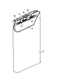
- FIG. 1 is a schematic perspective view with a part cut away of a non-aqueous electrolyte secondary battery according to an embodiment of the present invention
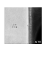
- FIG. It is a cross-sectional TEM photograph of the first region of the positive electrode active material particles, where region (a) is the surface of the composite oxide, region (b) is the metal oxide of the coating material, and region (c) is the phosphorus coat of the coating material.
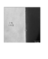
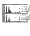
- FIG. 4 is a diagram showing the amount MO of phosphorus detected by EDX analysis of the first region; It is a cross-sectional TEM photograph of the second region of the positive electrode active material particles, where region (a) shows the surface of the composite oxide and region (b) shows the region where the binder exists.
- FIG. 4 is a diagram showing the amount of phosphorus detected by EDX analysis of the second region MS.
- a non-aqueous electrolyte secondary battery includes a positive electrode, a negative electrode, and a non-aqueous electrolyte.
- the positive electrode contains positive electrode active material particles.
- the positive electrode active material particles include a composite oxide containing lithium and a transition metal (hereinafter also referred to as "composite oxide A") and a coating material covering at least part of the surface of the composite oxide.
- the coating material contains a metal oxide (hereinafter also referred to as "metal oxide B”) and a phosphorus compound covering at least part of the surface of metal oxide B.
- metal oxide B a metal oxide
- phosphorus compound covering at least part of the surface of metal oxide B is also referred to as "phosphorus coat”.
- the structure of the phosphorus coat is not particularly limited, and the presence of the phosphorus coat can be confirmed by detecting the P element.
- Composite oxide A is the portion (positive electrode active material portion) that develops capacity by charging and discharging lithium ions.
- the coating material or metal oxide B is an additive to the positive electrode active material, and itself does not need to develop capacity. In other words, the composite oxide A is different from the metal oxide B.
- the phosphorus compound contained in the non-aqueous electrolyte may be a phosphate ester compound having at least one alkenyl group in one molecule.
- a phosphate ester compound having at least one alkenyl group in one molecule is also referred to as compound A.
- Compound A has a high affinity with the surface of metal oxide B.
- Both the metal oxide B and the phosphorus coat have a function of protecting the surface of the composite oxide A, limiting side reactions (hereinafter referred to as “protection function”), and suppressing metal elution from the composite oxide A. (hereinafter referred to as “elution suppression function"). Both the protection function and the elution suppression function contribute to the improvement of cycle characteristics.
- the amount of metal oxide B required to increase the coverage of the surface of composite oxide A with the coating material is greater than when only metal oxide B is used as the coating material. A small amount is sufficient.
- the thickness of the metal oxide B adhering to the surface of the composite oxide A may be sufficiently thin.
- the coating may consist of a small amount of metal oxide B and a small amount of phosphorus coat. The increase in internal resistance due to such a coating is small.
- the surface of composite oxide A may have a first region covered with island-shaped metal oxide B and a second region other than the first region.
- the second region may not be covered with metal oxide B, but a smaller amount of metal oxide B may be detected than in the first region.
- Lithium ions enter and leave the composite oxide A more easily in the second region than in the first region.
- the second region contributes to further reduction of internal resistance.
- the amount MA of the metal contained in the metal oxide B detected in the first region and the amount of metal contained in the metal oxide B detected in the second region is MA>MB, may satisfy MA>2MB, or may satisfy MA>3MB.
- the quantitative relationship between MA and MB is determined by the abundance ratio of metal atoms contained in metal oxide B.
- the atomic ratio of the metal (MY) derived from the metal oxide B to the metal (MX) derived from the composite oxide A: MY/MX is, for example, 2 or less. It is desirable to have In this case, it can be inferred that a thin layer of the metal oxide B (for example, a thickness of 1 nm or more and 3 nm or less) is distributed like islands on the surface of the composite oxide A.
- Compound A is a phosphoric acid ester (organic phosphoric acid) having at least one alkenyl group in one molecule.
- Compound A may be mixed in the non-aqueous electrolyte used in the battery.
- a phosphorus coat can be easily formed on the surface of metal oxide B covering the surface of composite oxide A.
- the phosphate triester preferably contains triallyl phosphate.
- Triallyl phosphate is easily dissolved in a non-aqueous electrolyte, and a non-aqueous electrolyte with a lower viscosity can be prepared.
- Triallyl phosphate preferably accounts for 50% by mass or more of the phosphate triester, and triallyl phosphate may be 70% by mass or more, or may be 90% by mass or more.
- the content of compound A in the non-aqueous electrolyte may be 2% by mass or less, may be 0.25% by mass or more and 2% by mass or less, or may be 0.25% by mass or more and 1.5% by mass. % or less, or 0.25% by mass or more and 1.3% by mass or less.
- the content of compound A may be within the above range. In this case, cycle characteristics are likely to be improved.
- the thickness of the metal oxide B adhering to the surface of the composite oxide A is, for example, in the range of 1 nm or more and 5 nm or less.
- the thickness of the metal oxide B may be 1 nm or more and 3 nm or less.
- Composite oxide A is a portion that develops capacity as a positive electrode active material.
- Composite oxide A contains lithium and a metal other than lithium.
- Metals other than lithium include at least transition metals, and may include metals other than transition metals.
- the transition metal may include at least one selected from the group consisting of Ni, Co, Mn, Fe, Cu, Cr, Ti, Nb, Zr, V, Ta and Mo, for example.
- Metals other than transition metals may include, for example, at least one selected from the group consisting of Al, Mg, Ca, Sr, Zn and Si.
- Composite oxide A can be obtained, for example, by mixing a lithium compound and a compound containing a metal other than lithium obtained by a coprecipitation method or the like, and firing the mixture under predetermined conditions.
- the average particle size means the particle size (volume average particle size) at which the volume integrated value is 50% in the particle size distribution measured by the laser diffraction scattering method. Such an average particle size is sometimes referred to as D50.
- the transition metal preferably contains at least Ni.
- Ni is less expensive than Co and is advantageous for increasing the capacity.
- the atomic ratio of Ni to all metals other than lithium may be, for example, 0.3 or more and less than 1, 0.5 or more and less than 1, or 0.75 or more and less than 1.
- Composite oxide A may have a layered rock salt structure.
- the composite oxide A may contain Ni, Co, and at least one of Al and Mn.
- the atomic ratio of the metal derived from the metal oxide B to Ni derived from the composite oxide A may be 2 or less on the outermost surface of the positive electrode mixture.
- the atoms of Al derived from Al 2 O 3 with respect to Ni derived from the composite oxide A on the outermost surface of the positive electrode mixture may be 2 or less. In this case, it can be inferred that a thin layer of the metal oxide B is distributed like islands on the surface of the composite oxide A.
- the content of the elements constituting the composite oxide A can be measured by an inductively coupled plasma atomic emission spectroscopy (ICP-AES), EPMA, EDX, or the like.
- ICP-AES inductively coupled plasma atomic emission spectroscopy
- a method of coating the surface of composite oxide A with a coating material includes, for example, a first step of coating the surface of composite oxide A with metal oxide B, and a second step of coating the surface of metal oxide B with a phosphorus coat. and a step.
- the first step may be a step of forming island-like first regions scattered on the surface of the composite oxide A.
- the surface of composite oxide A has a second region not covered with metal oxide B.
- the second step may be a step of adhering the compound A or its residue to the surface of the metal oxide B.
- a liquid phase method or a vapor phase method can be used as a method for coating the surface of the composite oxide A with the metal oxide B.
- the liquid phase method includes a wet method, a spray coating method, a dip coating method and the like.
- the vapor phase method includes chemical vapor deposition (CVD) method, atomic layer deposition (ALD) method, sputtering method, and the like.
- step (1A) for example, a positive electrode slurry in which a positive electrode mixture is dispersed in a dispersion medium is applied to the surface of a positive electrode current collector, the coating is dried, and if necessary, rolled to form a positive electrode mixture layer.
- the positive electrode material mixture layer may be formed on one surface of the positive electrode current collector, or may be formed on both surfaces.
- the positive electrode mixture contains at least composite oxide A, and may further contain a binder, a conductive agent, and the like. N-methyl-2-pyrrolidone (NMP) or the like is used as the dispersion medium.
- NMP N-methyl-2-pyrrolidone
- Examples of conductive agents include carbon black, carbon fiber, metal fiber, and carbon fluoride.
- a metal foil can be used for the positive electrode current collector.
- metals forming the positive electrode current collector include aluminum, titanium, alloys containing these metal elements, and stainless steel.
- the thickness of the positive electrode current collector is not particularly limited, it is, for example, 3 to 50 ⁇ m.
- a metal oxide B is formed on the surface of the composite oxide A by a wet method, spray coating method, dip coating method, chemical vapor deposition (CVD) method, atomic layer deposition (ALD) method, sputtering method, or the like.
- the ALD method can deposit a metal oxide on the surface of the composite oxide.
- ALD can be performed at a temperature of 100 to 400.degree. C., as opposed to a vapor phase method such as CVD, which is generally performed at a temperature of 400 to 900.degree.
- the ALD method is superior in that it can suppress thermal damage to the electrodes.
- island-shaped metal oxide B can be scattered on the surface of composite oxide A by controlling the film forming conditions.
- the deposition amount of the metal oxide B can be controlled by the number of cycles in which one cycle is "supply of source gas ⁇ exhaust (purge) of source gas ⁇ supply of oxidant ⁇ exhaust (purge) of oxidant".
- oxidizing agents used in the ALD method include water, oxygen, and ozone.
- the oxidant may be supplied to the reaction chamber as an oxidant-based plasma.
- Al-containing precursors include trimethylaluminum ((CH 3 ) 3 Al), triethylaluminum ((C 2 H 5 ) 3 Al), and the like.
- the first step includes, for example, a step (1a) of attaching the metal oxide B to at least part of the surface of the composite oxide A, and a step (1a) of attaching the metal oxide B to the surface of the positive electrode current collector. and a step (1b) of forming a positive electrode mixture layer containing the substance A to obtain a positive electrode intermediate.
- step (1a) metal oxide B can be attached to the surface of composite oxide A by a wet method, spray coating method, dip coating method, chemical vapor deposition (CVD) method, sputtering method, or the like.
- the step (1a) includes, for example, a step (1a-1) of adhering the raw material solution to the surface of the composite oxide A, and a step (1a-2) of heating and drying the composite oxide A with the raw material solution adhered to the surface. including.
- the step (1a-1) is, for example, a step of adding the composite oxide A to the raw material solution and dispersing it by stirring.
- the step (1a-2) includes a step of removing the dispersion medium adhering to the surface of the composite oxide A by heat drying, and reacting the raw materials adhering to the surface of the composite oxide A to form the metal oxide B Also serves as a step of generating.
- an aqueous solution containing the raw material for example, an aqueous solution containing the raw material is used.
- a compound capable of generating metal oxide B by decomposition reaction by heating can be used.
- examples of such compounds include metal salts of organic acids such as citric acid, maleic acid and lactic acid, and organometallic complexes.
- step (1b) similarly to step (1A), a positive electrode slurry is prepared, the positive electrode slurry is applied to the surface of the positive electrode current collector, the coating is dried, and if necessary, rolled to form a positive electrode mixture. Layers should be formed.
- the second step includes, for example, a step (2A) of preparing a non-aqueous electrolyte containing compound A, and a step of contacting the non-aqueous electrolyte containing compound A with composite oxide A whose surface is coated with metal oxide B. (2B) and.
- step (2B) compound A, which has a high affinity for metal oxide B, preferentially or selectively adheres to the surface of metal oxide B, or reacts therewith.
- step (2B) for example, constructing an electrode group comprising the positive electrode intermediate obtained in step (1B) or step (1b), a negative electrode, and a separator disposed between the positive electrode intermediate and the negative electrode.
- You may contact an electrode group and a non-aqueous electrolyte.
- the battery may be assembled by housing the electrode group in a battery case, injecting a non-aqueous electrolyte into the battery case housing the electrode group, and closing the opening of the battery case with a sealing plate.
- the positive electrode includes, for example, a positive electrode current collector and a positive electrode mixture layer carried on the surface of the positive electrode current collector.
- the positive electrode mixture layer contains positive electrode active material particles as an essential component.
- the positive electrode active material particles comprise a composite oxide A and a coating material adhering to the surface of the composite oxide A.
- the negative electrode may have at least a negative electrode current collector, and may include a negative electrode mixture layer carried on the surface of the negative electrode current collector.
- the non-aqueous electrolyte secondary battery may be a lithium secondary battery (lithium metal secondary battery) in which lithium metal is deposited at the negative electrode during charging and dissolved during discharging, and lithium ions are absorbed and released during charging and discharging.
- An accompanying lithium ion secondary battery may also be used.
- the negative electrode mixture layer can be formed, for example, by applying a negative electrode slurry in which a negative electrode mixture is dispersed in a dispersion medium to the surface of the negative electrode current collector, drying the coating film, and rolling it if necessary.
- the negative electrode mixture layer may be formed on one surface of the negative electrode current collector, or may be formed on both surfaces.
- the dispersion medium for example, water or NMP is used.
- the negative electrode mixture contains a negative electrode active material as an essential component, and may contain a binder, a conductive agent, a thickener, etc. as optional components.
- a binder e.g., a conductive agent
- a thickener e.g., a rubber material
- SBR styrene-butadiene copolymer rubber
- thickeners include carboxymethyl cellulose (CMC) and modified products thereof (Na salts, etc.).
- the negative electrode active material may contain a carbon material that absorbs and releases lithium ions.
- Carbon materials that occlude and release lithium ions include graphite (natural graphite, artificial graphite), easily graphitizable carbon (soft carbon), non-graphitizable carbon (hard carbon), and the like. Among them, graphite is preferable because it has excellent charging/discharging stability and low irreversible capacity.
- the negative electrode active material may contain an alloy material.
- An alloy-based material is a material containing at least one metal capable of forming an alloy with lithium. Examples of alloy-based materials include silicon, tin, silicon alloys, tin alloys, and silicon compounds.
- a composite material comprising a lithium ion conducting phase and a silicon phase dispersed in the phase may be used as the silicon compound.
- a silicate phase such as a lithium silicate phase, a silicon oxide phase in which 95 mass % or more is silicon dioxide, a carbon phase, or the like may be used.
- An alloy material and a carbon material may be used together as the negative electrode active material.
- the ratio of the carbon material to the total of the alloy material and the carbon material is, for example, preferably 80% by mass or more, more preferably 90% by mass or more.
- the shape and thickness of the negative electrode current collector can be selected from the shape and range according to the positive electrode current collector.
- metals forming the negative electrode current collector include copper (Cu), nickel (Ni), iron (Fe), and alloys containing these metal elements.
- the non-aqueous electrolyte includes a non-aqueous solvent and a lithium salt dissolved in the non-aqueous solvent.
- the non-aqueous electrolyte may contain Compound A.
- the lithium salt concentration in the non-aqueous electrolyte is preferably, for example, 0.5 mol/L or more and 2 mol/L or less. By controlling the lithium salt concentration within the above range, it is possible to obtain a non-aqueous electrolyte having excellent ion conductivity and moderate viscosity.
- the lithium salt concentration is not limited to the above.
- cyclic carbonate for example, cyclic carbonate, chain carbonate, cyclic carboxylate, chain carboxylate, and the like are used.
- Cyclic carbonates include propylene carbonate (PC), ethylene carbonate (EC), and the like.
- the cyclic carbonate may include a fluorinated cyclic carbonate such as fluoroethylene carbonate (FEC), and a cyclic carbonate having a carbon-carbon unsaturated bond such as vinylene carbonate (VC) and vinylethylene carbonate.
- Chain carbonates include diethyl carbonate (DEC), ethylmethyl carbonate (EMC), dimethyl carbonate (DMC) and the like.
- Cyclic carboxylic acid esters include ⁇ -butyrolactone (GBL) and ⁇ -valerolactone (GVL).
- Chain carboxylic acid esters include methyl formate, ethyl formate, propyl formate, methyl acetate, ethyl acetate, propyl acetate, methyl propionate, ethyl propionate, and propyl propionate.
- the non-aqueous solvent may be used singly or in combination of two or more.
- a known lithium salt can be used as the lithium salt.
- Preferred lithium salts include, for example, LiClO4 , LiBF4 , LiPF6 , LiAlCl4 , LiSbF6 , LiSCN , LiCF3SO3 , LiCF3CO2 , LiAsF6 , LiB10Cl10 , lithium lower aliphatic carboxylate , LiCl, LiBr, LiI, borates, imide salts and the like.
- Borate salts include lithium bisoxalate borate and lithium difluorooxalate borate.
- the imide salts include lithium bis(fluorosulfonyl)imide (LiN( FSO2)2), lithium bistrifluoromethanesulfonimide (LiN(CF3SO2)2 ) , lithium trifluoromethanesulfonate nonafluorobutanesulfonate imido. (LiN(CF 3 SO 2 )(C 4 F 9 SO 2 )), lithium bispentafluoroethanesulfonic acid imide (LiN(C 2 F 5 SO 2 ) 2 ), and the like. Lithium salts may be used singly or in combination of two or more.
- separator Generally, a separator is interposed between the positive electrode and the negative electrode.
- the separator has high ion permeability and moderate mechanical strength and insulation.
- a microporous thin film, a woven fabric, a nonwoven fabric, or the like can be used as the separator.
- Polyolefins such as polypropylene and polyethylene are preferable as the material of the separator.
- An example of the structure of a non-aqueous electrolyte secondary battery is a structure in which an electrode group, in which a positive electrode and a negative electrode are wound with a separator interposed therebetween, is accommodated in an exterior body together with a non-aqueous electrolyte.
- an electrode group in which a positive electrode and a negative electrode are wound with a separator interposed therebetween
- a laminated electrode group in which a positive electrode and a negative electrode are laminated with a separator interposed therebetween may be used.
- the shape of the nonaqueous electrolyte secondary battery is not limited, either, and may be, for example, cylindrical, square, coin, button, laminate, or the like.
- non-aqueous electrolyte secondary battery As an example of the non-aqueous electrolyte secondary battery according to the present invention, the structure of a prismatic non-aqueous electrolyte secondary battery will be described below with reference to FIG.
- the battery includes a prismatic battery case 4 with a bottom, and an electrode group 1 and a non-aqueous electrolyte (not shown) housed in the battery case 4 .
- the electrode group 1 has a long strip-shaped negative electrode, a long strip-shaped positive electrode, and a separator interposed therebetween.
- the negative electrode current collector of the negative electrode is electrically connected to a negative electrode terminal 6 provided on a sealing plate 5 via a negative electrode lead 3 .
- the negative electrode terminal 6 is insulated from the sealing plate 5 by a resin gasket 7 .
- the positive current collector of the positive electrode is electrically connected to the rear surface of the sealing plate 5 via the positive lead 2 . That is, the positive electrode is electrically connected to the battery case 4 which also serves as a positive electrode terminal.
- the peripheral edge of the sealing plate 5 is fitted into the open end of the battery case 4, and the fitted portion is laser-welded.
- the sealing plate 5 has an injection hole for a non-aqueous electrolyte, which is closed by
- NMP was added to the positive electrode mixture and stirred to prepare a positive electrode slurry.
- a mixture of positive electrode active material particles, acetylene black (AB), and polyvinylidene fluoride (PVDF) was used as the positive electrode mixture.
- Composite oxide particles (average particle size (D50): 4 ⁇ m) having a composition of layered rock salt-type LiNi 0.35 Co 0.35 Mn 0.30 (NCM) were used as the positive electrode active material.
- the mass ratio of the positive electrode active material, AB, and PVDF was 100:2:2.
- a positive electrode slurry was applied to the surface of an aluminum foil, the coating film was dried, and then rolled to form a positive electrode mixture layer.
- the positive electrode mixture layers were formed on both sides of the aluminum foil. Further, by ALD method (temperature: 120° C., precursor: trimethylaluminum, oxidant: H 2 O, pressure: several Torr, 10 cycles), island-shaped Al 2 particles were formed on the surface of the composite oxide particles in the positive electrode mixture layer. O3 was deposited in a spotted manner. Thus, a positive electrode intermediate was obtained.
- the atomic ratio Al/Ni on the outermost surface of the composite oxide particles in the positive electrode intermediate obtained by the method described above was 2 or less.
- Preparation of negative electrode Water was added to the negative electrode mixture and stirred to prepare a negative electrode slurry.
- a mixture of artificial graphite (average particle size: 20 ⁇ m), styrene-butadiene rubber (SBR), and sodium carboxymethylcellulose (CMC) was used as the negative electrode mixture.
- SBR styrene-butadiene rubber
- CMC sodium carboxymethylcellulose
- the mass ratio of artificial graphite, SBR, and CMC was 100:1:1.
- a negative electrode slurry was applied to the surface of a copper foil, the coating film was dried, and then rolled to produce a negative electrode having negative electrode mixture layers formed on both sides of the copper foil.
- LiPF 6 was dissolved in a mixed solvent of fluoroethylene carbonate (FEC) and dimethyl carbonate (DMC) (volume ratio 2:8), and triallyl phosphate (TP) was further added to obtain a non-aqueous electrolyte.
- FEC fluoroethylene carbonate
- DMC dimethyl carbonate
- TP triallyl phosphate
- the concentration of LiPF 6 in the non-aqueous electrolyte was 1 mol/L.
- the content of TP in the non-aqueous electrolyte was the value shown in Table 1.
- a positive electrode lead made of Al was attached to the positive electrode intermediate obtained above.
- a negative electrode lead made of Ni was attached to the negative electrode obtained above.
- the positive electrode intermediate and the negative electrode were spirally wound with a polyethylene thin film (separator) having a two-layer structure interposed therebetween to prepare a wound electrode group.
- the electrode group was housed in a bag-shaped exterior body formed of a laminate sheet having an Al layer, and after the above non-aqueous electrolyte was injected, the exterior body was sealed to produce a non-aqueous electrolyte secondary battery.
- the non-aqueous electrolyte permeates into the positive electrode mixture layer, and the TP adheres to the surface of the Al 2 O 3 scattered island-like on the surface of the composite oxide particles to form a coating material.
- the batteries of Examples 1 to 4 are A1 to A4, respectively.
- a battery B2 was produced in the same manner as the battery A1 of Example 1, except that the nonaqueous electrolyte did not contain TP in the preparation of the nonaqueous electrolyte.
- a battery B3 was produced in the same manner as the battery A2 of Example 2, except that the surface of the composite oxide particles in the positive electrode mixture layer was not coated with Al 2 O 3 in the production of the positive electrode intermediate.
- the batteries A1 to A4 of Examples 1 to 4 and the batteries B1 to B3 of Comparative Examples 1 to 3 were evaluated as follows.
- FIG. 2 is a cross-sectional TEM photograph of the first region of the positive electrode active material particles taken, in which the region (a) is the surface of the composite oxide, the region (b) is the metal oxide of the coating material, and the region (c) is The phosphorus coat of the covering material is shown.
- FIG. 3 is a diagram showing the amount MO of phosphorus detected by EDX analysis of the first region.
- FIG. 4 is a cross-sectional TEM photograph of the second region of the positive electrode active material particles, where region (a) shows the surface of the composite oxide and region (b) shows the PDVF existing region.
- FIG. 5 is a diagram showing the amount MS of phosphorus detected by EDX analysis of the second region.
- the surface of the composite oxide A (positive electrode active material) is uniformly dotted with first regions (FIG. 2) coated with island-shaped metal oxide B (Al 2 O 3 ), and the metal It was confirmed that the second region (FIG. 4), in which oxide B (Al 2 O 3 ) is almost absent, is evenly present on the surface of composite oxide A.
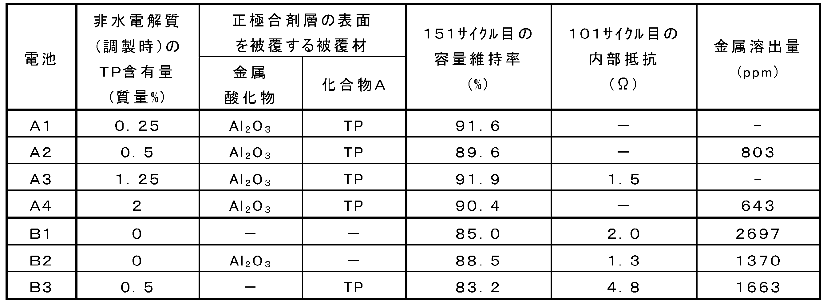
- Batteries A1 to A4 had higher capacity retention rates than batteries B1 to B3. Since no coating material was formed on the surface of composite oxide A in battery B1, the non-aqueous electrolyte and the composite oxide particles came into contact with each other, side reactions and metal elution occurred, and the capacity retention rate decreased. In the battery B2, the surface of the composite oxide A was coated with Al 2 O 3 , but no phosphorus coat was formed, so the capacity retention rate was lowered. In Battery B3, the surface of composite oxide A was covered with TP, but the surface of composite oxide A was not covered with Al 2 O 3 , so the internal resistance (resistance of the positive electrode) increased and the capacity retention rate decreased. did. In battery A3, although the TP content was higher than that in battery B3, the internal resistance (resistance of the positive electrode) was lower than that in battery B3 because the surface of composite oxide A was covered with the coating material.
- the non-aqueous electrolyte secondary battery according to the present invention is suitably used, for example, as a power source for mobile devices such as smartphones, a power source for vehicles such as electric vehicles, and a storage device for natural energy such as sunlight. While the invention has been described in terms of presently preferred embodiments, such disclosure is not to be construed in a limiting sense. Various alterations and modifications will no doubt become apparent to those skilled in the art to which the invention pertains after reading the above disclosure. Therefore, the appended claims are to be interpreted as covering all variations and modifications without departing from the true spirit and scope of the invention.
Landscapes
- Chemical & Material Sciences (AREA)
- Chemical Kinetics & Catalysis (AREA)
- Electrochemistry (AREA)
- General Chemical & Material Sciences (AREA)
- Engineering & Computer Science (AREA)
- Inorganic Chemistry (AREA)
- Manufacturing & Machinery (AREA)
- Composite Materials (AREA)
- General Physics & Mathematics (AREA)
- Condensed Matter Physics & Semiconductors (AREA)
- Physics & Mathematics (AREA)
- Materials Engineering (AREA)
- Battery Electrode And Active Subsutance (AREA)
- Secondary Cells (AREA)
Abstract
Description
本発明の新規な特徴を添付の請求の範囲に記述するが、本発明は、構成および内容の両方に関し、本発明の他の目的および特徴と併せ、図面を照合した以下の詳細な説明によりさらによく理解されるであろう。
化合物Aは、1分子内に少なくとも1つのアルケニル基を有するリン酸エステル(有機リン酸)である。化合物Aは、電池に用いる非水電解質に混入させてもよい。化合物Aを含む非水電解質を用いて電池を製造することで、複合酸化物Aの表面を覆う金属酸化物Bの表面にリンコートを容易に形成することができる。

金属酸化物Bに含まれる金属は、例えば、アルミニウム、ケイ素、チタン、マグネシウム、ジルコニウム、ニオブ、ゲルマニウム、カルシウムおよびストロンチウムからなる群より選択される少なくとも1種であり得る。金属酸化物Bは、例えば、アルミニウム酸化物(例えばAl2O3やシリカアルミナ)、ケイ素酸化物(例えばSiO2)、チタン酸化物(例えばTiO2)、マグネシウム酸化物(例えばMgO)、ジルコニウム酸化物(例えばZrO2)、ニオブ酸化物、ゲルマニウム酸化物、カルシウム酸化物およびストロンチウム酸化物からなる群より選択される少なくとも1種であり得る。
複合酸化物Aは、正極活物質として容量を発現する部分である。複合酸化物Aは、リチウムと、リチウム以外の金属とを含有する。リチウム以外の金属は、少なくとも遷移金属を含み、遷移金属以外の金属を含んでもよい。遷移金属は、例えば、Ni、Co、Mn、Fe、Cu、Cr、Ti、Nb、Zr、V、TaおよびMoからなる群より選択される少なくとも1種を含んでもよい。遷移金属以外の金属は、例えば、Al、Mg、Ca、Sr、ZnおよびSiからなる群より選択される少なくとも1種を含んでもよい。
複合酸化物Aの表面を被覆材で被覆する方法は、例えば、複合酸化物Aの表面を金属酸化物Bで被覆する第1工程と、金属酸化物Bの表面をリンコートで被覆する第2工程とを含む。第1工程は、複合酸化物Aの表面に点在する島状の第1領域を形成する工程であってもよい。この場合、複合酸化物Aの表面は、金属酸化物Bで被覆されない第2領域を有する。第2工程は、金属酸化物Bの表面に化合物Aもしくはその残基を付着させる工程であればよい。
複合酸化物Aの表面を金属酸化物Bで被覆する方法として、液相法または気相法を用いることができる。液相法としては、湿式法、スプレーコーティング法、ディップコーティング法等が挙げられる。気相法としては、化学気相成長(CVD)法、原子層堆積(ALD)法、スパッタ法等が挙げられる。
第1工程は、例えば、正極集電体の表面に複合酸化物Aを含む正極合剤層を形成する工程(1A)と、正極合剤層中の複合酸化物Aの表面の少なくとも一部に金属酸化物Bを付着させて、正極中間体を得る工程(1B)とを含む。
第1工程は、例えば、複合酸化物Aの表面の少なくとも一部に、金属酸化物Bを付着させる工程(1a)と、正極集電体の表面に、金属酸化物Bを付着させた複合酸化物Aを含む正極合剤層を形成して、正極中間体を得る工程(1b)とを含んでもよい。
第2工程は、金属酸化物Bの表面に化合物Aを接触させ、金属酸化物Bと、金属酸化物Bの表面の少なくとも一部を覆うリンコートとを含む被覆材を形成し、正極を得る工程である。第2工程は、例えば、化合物Aを含む非水電解質を調製する工程(2A)と、化合物Aを含む非水電解質と表面が金属酸化物Bで被覆された複合酸化物Aとを接触させる工程(2B)とを含む。工程(2B)では、金属酸化物Bとの親和性の高い化合物Aが金属酸化物Bの表面に優先的もしくは選択的に付着し、もしくは反応する。
(正極)
正極は、例えば、正極集電体と、正極集電体の表面に担持された正極合剤層と備える。正極合剤層は、正極活物質粒子を必須成分として含む。正極活物質粒子は、複合酸化物Aと、複合酸化物Aの表面に付着する被覆材とを具備する。
負極は、少なくとも負極集電体を有すればよく、負極集電体の表面に担持された負極合剤層を備えてもよい。すなわち、非水電解質二次電池は、負極で、リチウム金属が、充電時に析出し、放電時に溶解するリチウム二次電池(リチウム金属二次電池)でもよく、充放電においてリチウムイオンの吸蔵および放出を伴うリチウムイオン二次電池でもよい。
非水電解質は、非水溶媒と、非水溶媒に溶解したリチウム塩とを含む。非水電解質は、化合物Aを含み得る。非水電解質におけるリチウム塩の濃度は、例えば、0.5mol/L以上、2mol/L以下が好ましい。リチウム塩濃度を上記範囲に制御することで、イオン伝導性に優れ、適度の粘性を有する非水電解質を得ることができる。ただし、リチウム塩濃度は上記に限定されない。
一般に、正極と負極との間にはセパレータが介在する。セパレータは、イオン透過度が高く、適度な機械的強度および絶縁性を備えている。セパレータとしては、微多孔薄膜、織布、不織布等を用いることができる。セパレータの材質としては、ポリプロピレン、ポリエチレン等のポリオレフィンが好ましい。
[正極中間体の作製]
正極合剤にNMPを加えて攪拌し、正極スラリを調製した。正極合剤には、正極活物質粒子と、アセチレンブラック(AB)と、ポリフッ化ビニリデン(PVDF)との混合物を用いた。正極活物質には、層状岩塩型のLiNi0.35Co0.35Mn0.30(NCM)の組成を有する複合酸化物粒子(平均粒径(D50)4μm)を用いた。正極合剤において、正極活物質と、ABと、PVDFとの質量比は、100:2:2とした。
負極合剤に水を加えて攪拌し、負極スラリを調製した。負極合剤には、人造黒鉛(平均粒径20μm)と、スチレン-ブタジエンゴム(SBR)と、カルボキシメチルセルロースナトリウム(CMC)との混合物を用いた。負極合剤において、人造黒鉛と、SBRと、CMCとの質量比は、100:1:1とした。銅箔の表面に負極スラリを塗布し、塗膜を乾燥させた後、圧延して、銅箔の両面に負極合剤層が形成された負極を作製した。
フルオロエチレンカーボネート(FEC)とジメチルカーボネート(DMC)との混合溶媒(体積比2:8)にLiPF6を溶解させ、リン酸トリアリル(TP)を更に含ませて、非水電解質を得た。非水電解質中のLiPF6の濃度は、1mol/Lとした。非水電解質中のTPの含有率は、表1に示す値とした。
上記で得られた正極中間体にAl製の正極リードを取り付けた。上記で得られた負極にNi製の負極リードを取り付けた。不活性ガス雰囲気中で、正極中間体と負極とを2層構造のポリエチレン薄膜(セパレータ)を介して渦巻状に巻回し、巻回型の電極群を作製した。電極群を、Al層を備えるラミネートシートで形成される袋状の外装体に収容し、上記の非水電解質を注入した後、外装体を封止して非水電解質二次電池を作製した。電極群を外装体に収容する際、正極リードおよび負極リードの一部は、外装体より外部に露出させた。電池内において正極合剤層中に非水電解液が浸透し、複合酸化物粒子の表面に島状に点在するAl2O3の表面にTPが付着して被覆材が形成される。なお、表1中、実施例1~4の電池は、それぞれA1~A4である。
正極中間体の作製において、正極合剤層中の複合酸化物粒子の表面をAl2O3で被覆しなかった。非水電解質の調製において、非水電解質にTPを含ませなかった。上記以外、実施例1の電池A1と同様の方法により、電池B1を作製した。
非水電解質の調製において、非水電解質にTPを含ませなかった以外、実施例1の電池A1と同様の方法により、電池B2を作製した。
正極中間体の作製において、正極合剤層中の複合酸化物粒子の表面をAl2O3で被覆しなかった以外、実施例2の電池A2と同様の方法により、電池B3を作製した。
(1)第1充放電
電圧が4.5Vになるまで0.2Cの電流で定電流充電を行った後、電流が0.05Cになるまで4.5Vの電圧で定電圧充電を行った。その後、電圧が2.5Vになるまで0.2Cの電流で定電流放電を行った。充電と放電との間の休止時間は60分とした。充放電は25℃の環境下で行った。
電圧が4.5Vになるまで0.3Cの電流で定電流充電を行った後、電圧が2.5Vになるまで0.5Cの電流で定電流放電を行った。充電と放電との間の休止時間は10分とした。充放電は25℃の環境下で行った。
上記(1)の第1充放電を1サイクルの後、上記(2)の第2充放電を24サイクル行う工程を1セットとして、6セット行った。すなわち、1サイクル目、26サイクル目、51サイクル目、76サイクル目、101サイクル目、126サイクル目、151サイクル目では、上記(1)の第1充放電を行った。上記以外のサイクルでは、上記(2)の第2充放電を行った。1サイクル目の第1充放電の放電容量に対する、151サイクル目の第1充放電の放電容量の割合を、151サイクル時の容量維持率として求めた。
電池A3および電池B1~B3について、101サイクル目の第1充放電後、満充電量の50%まで充電した。その後、0.3Cの電流Iで定電流放電を30秒間行い、放電開始時点から放電開始後30秒経過時点までの電圧降下分ΔVを測定し、ΔV/Iを算出し、内部抵抗とした。
評価1の後、電池を分解し、2層構造のポリエチレン薄膜(セパレータ)と負極とを取り出した。2層構造のポリエチレン薄膜の負極側を剥がし、その中に含まれる正極活物質由来の金属と、負極中に存在する正極活物質由来の金属との合計量を、正極からの金属溶出量として測定し、正極に含まれる正極活物質に対する質量比率(ppm)を求めた。
評価結果を表1に示す。
本発明を現時点での好ましい実施態様に関して説明したが、そのような開示を限定的に解釈してはならない。種々の変形および改変は、上記開示を読むことによって本発明に属する技術分野における当業者には間違いなく明らかになるであろう。したがって、添付の請求の範囲は、本発明の真の精神および範囲から逸脱することなく、すべての変形および改変を包含する、と解釈されるべきものである。
Claims (16)
- 正極と、負極と、非水電解質と、を備え、
前記正極は、正極活物質粒子を含む正極合剤を有し、
前記正極活物質粒子は、リチウムと遷移金属とを含有する複合酸化物と、前記複合酸化物の表面の少なくとも一部を覆う被覆材と、を備え、
前記被覆材は、金属酸化物と、前記金属酸化物の表面の少なくとも一部を覆うリン化合物と、を含む、非水電解質二次電池。 - 前記複合酸化物の表面が、島状の前記金属酸化物で覆われた第1領域と、前記第1領域以外の第2領域を有する、請求項1に記載の非水電解質二次電池。
- 前記第1領域が、前記複合酸化物の表面に点在している、請求項1または2に記載の非水電解質二次電池。
- 前記金属酸化物の表面で検出されるリンの量MOと、前記第2領域で検出されるリンの量MSとが、MO>MSの関係を有する、請求項1~3のいずれか1項に記載の非水電解質二次電池。
- MO>3MSを満たす、請求項4に記載の非水電解質二次電池。
- 前記金属酸化物は、アルミニウム、ケイ素、チタン、マグネシウム、ジルコニウム、ニオブ、ゲルマニウム、カルシウムおよびストロンチウムからなる群より選択される少なくとも1種の元素を含む、請求項1~5のいずれか1項に記載の非水電解質二次電池。
- 前記複合酸化物は、層状岩塩型構造を有し、かつNiと、Coと、AlおよびMnの少なくとも一方と、を含む、請求項1~6のいずれか1項に記載の非水電解質二次電池。
- 前記正極合剤の最表面において、前記複合酸化物に由来するNiに対する前記金属酸化物に由来する金属の原子比が、2以下である、請求項7に記載の非水電解質二次電池。
- 前記非水電解質は、リン酸エステル化合物を含み、
前記リン酸エステル化合物は、1分子内に少なくとも1つのアルケニル基を有する、請求項1~8のいずれか1項に記載の非水電解質二次電池。 - 前記非水電解質中の前記リン酸エステル化合物の含有率が2質量%以下である、請求項9に記載の非水電解質二次電池。
- 前記アルケニル基は、ビニル基、1-プロぺニル基、2-プロぺニル基、イソプロペニル基、1-ブテニル基、2-ブテニル基および3-ブテニル基からなる群より選択される少なくとも1種を含む、請求項9または10に記載の非水電解質二次電池。
- 前記リン酸エステル化合物は、リン酸トリアリルを含む、請求項9~11のいずれか1項に記載の非水電解質二次電池。
- 正極と、負極と、非水電解質と、を備える非水電解質二次電池の製造方法であって、
(1A)正極集電体の表面に、リチウムと遷移金属とを含有する複合酸化物を含む正極合剤層を形成する工程と、
(1B)前記正極合剤層中の前記複合酸化物の表面の少なくとも一部に、金属酸化物を付着させて、正極中間体を得る工程と、
(2)前記金属酸化物の表面にリン酸エステル化合物を接触させ、前記金属酸化物と、前記金属酸化物の表面の少なくとも一部を覆うリン化合物と、を含む被覆材を形成して、正極を得る工程と、を含む、非水電解質二次電池の製造方法。 - 前記正極中間体を得る工程では、湿式法、スプレーコーティング法、ディップコーティング法、化学気相成長(CVD)法、原子層堆積(ALD)法およびスパッタ法からなる群より選択される少なくとも1つの方法で、前記複合酸化物の表面に前記金属酸化物を付着させる、請求項13に記載の非水電解質二次電池の製造方法。
- 正極と、負極と、非水電解質と、を備える非水電解質二次電池の製造方法であって、
(1a)リチウムと遷移金属とを含有する複合酸化物の表面の少なくとも一部に、金属酸化物を付着させる工程と、
(1b)正極集電体の表面に、前記金属酸化物を付着させた前記複合酸化物を含む正極合剤層を形成して、正極中間体を得る工程と、
(2)前記金属酸化物の表面にリン酸エステル化合物を接触させ、前記金属酸化物と、前記金属酸化物の表面の少なくとも一部を覆うリン化合物と、を含む被覆材を形成して、正極を得る工程と、を含む、非水電解質二次電池の製造方法。 - 前記金属酸化物を付着させる工程が、湿式法、スプレーコーティング法、ディップコーティング法、化学気相成長(CVD)法およびスパッタ法からなる群より選択される少なくとも1つの方法で行われる、請求項15に記載の非水電解質二次電池の製造方法。
Priority Applications (4)
| Application Number | Priority Date | Filing Date | Title |
|---|---|---|---|
| CN202280012264.1A CN116964778A (zh) | 2021-01-29 | 2022-01-24 | 非水电解质二次电池及其制造方法 |
| EP22745800.7A EP4287301A4 (en) | 2021-01-29 | 2022-01-24 | SECONDARY BATTERY WITH NON-AQUEOUS ELECTROLYTE AND METHOD FOR THE PRODUCTION THEREOF |
| JP2022578366A JP7796359B2 (ja) | 2021-01-29 | 2022-01-24 | 非水電解質二次電池およびその製造方法 |
| US18/274,368 US20240105912A1 (en) | 2021-01-29 | 2022-01-24 | Nonaqueous electrolyte secondary battery and method for manufacturing same |
Applications Claiming Priority (2)
| Application Number | Priority Date | Filing Date | Title |
|---|---|---|---|
| JP2021013965 | 2021-01-29 | ||
| JP2021-013965 | 2021-01-29 |
Publications (1)
| Publication Number | Publication Date |
|---|---|
| WO2022163579A1 true WO2022163579A1 (ja) | 2022-08-04 |
Family
ID=82653540
Family Applications (1)
| Application Number | Title | Priority Date | Filing Date |
|---|---|---|---|
| PCT/JP2022/002436 Ceased WO2022163579A1 (ja) | 2021-01-29 | 2022-01-24 | 非水電解質二次電池およびその製造方法 |
Country Status (5)
| Country | Link |
|---|---|
| US (1) | US20240105912A1 (ja) |
| EP (1) | EP4287301A4 (ja) |
| JP (1) | JP7796359B2 (ja) |
| CN (1) | CN116964778A (ja) |
| WO (1) | WO2022163579A1 (ja) |
Cited By (2)
| Publication number | Priority date | Publication date | Assignee | Title |
|---|---|---|---|---|
| WO2024142770A1 (ja) * | 2022-12-26 | 2024-07-04 | パナソニックIpマネジメント株式会社 | 被覆正極活物質、正極、および二次電池 |
| WO2026014425A1 (ja) * | 2024-07-08 | 2026-01-15 | 株式会社村田製作所 | 正極、二次電池および正極の製造方法 |
Citations (3)
| Publication number | Priority date | Publication date | Assignee | Title |
|---|---|---|---|---|
| WO2013047877A1 (ja) * | 2011-09-30 | 2013-04-04 | 旭硝子株式会社 | リチウムイオン二次電池用正極活物質、およびその製造方法 |
| JP2018524776A (ja) * | 2015-07-02 | 2018-08-30 | ユミコア | コバルト系リチウム金属酸化物カソード材料 |
| WO2021200394A1 (ja) * | 2020-03-31 | 2021-10-07 | パナソニックIpマネジメント株式会社 | 非水電解質二次電池 |
Family Cites Families (7)
| Publication number | Priority date | Publication date | Assignee | Title |
|---|---|---|---|---|
| JP2008071569A (ja) * | 2006-09-13 | 2008-03-27 | Sanyo Electric Co Ltd | 非水電解質二次電池用正極材料及び非水電解質二次電池 |
| JP5199844B2 (ja) * | 2008-11-21 | 2013-05-15 | 株式会社日立製作所 | リチウム二次電池 |
| JP6007942B2 (ja) * | 2014-05-19 | 2016-10-19 | トヨタ自動車株式会社 | 非水電解質二次電池およびその製造方法 |
| US11217817B2 (en) * | 2016-05-31 | 2022-01-04 | Umicore | Lithium ion batteries, electronic devices, and methods |
| JP6519577B2 (ja) * | 2016-12-22 | 2019-05-29 | トヨタ自動車株式会社 | リチウムイオン二次電池 |
| KR102363371B1 (ko) * | 2019-02-01 | 2022-02-14 | 삼성에스디아이 주식회사 | 리튬 이차 전지용 양극 활물질, 이의 제조방법 및 이를 포함하는 리튬 이차 전지 |
| CN112186248B (zh) * | 2020-09-30 | 2022-11-25 | 香河昆仑新能源材料股份有限公司 | 一种锂离子电池非水电解液及锂离子电池 |
-
2022
- 2022-01-24 CN CN202280012264.1A patent/CN116964778A/zh active Pending
- 2022-01-24 JP JP2022578366A patent/JP7796359B2/ja active Active
- 2022-01-24 WO PCT/JP2022/002436 patent/WO2022163579A1/ja not_active Ceased
- 2022-01-24 EP EP22745800.7A patent/EP4287301A4/en active Pending
- 2022-01-24 US US18/274,368 patent/US20240105912A1/en active Pending
Patent Citations (3)
| Publication number | Priority date | Publication date | Assignee | Title |
|---|---|---|---|---|
| WO2013047877A1 (ja) * | 2011-09-30 | 2013-04-04 | 旭硝子株式会社 | リチウムイオン二次電池用正極活物質、およびその製造方法 |
| JP2018524776A (ja) * | 2015-07-02 | 2018-08-30 | ユミコア | コバルト系リチウム金属酸化物カソード材料 |
| WO2021200394A1 (ja) * | 2020-03-31 | 2021-10-07 | パナソニックIpマネジメント株式会社 | 非水電解質二次電池 |
Non-Patent Citations (1)
| Title |
|---|
| See also references of EP4287301A4 * |
Cited By (2)
| Publication number | Priority date | Publication date | Assignee | Title |
|---|---|---|---|---|
| WO2024142770A1 (ja) * | 2022-12-26 | 2024-07-04 | パナソニックIpマネジメント株式会社 | 被覆正極活物質、正極、および二次電池 |
| WO2026014425A1 (ja) * | 2024-07-08 | 2026-01-15 | 株式会社村田製作所 | 正極、二次電池および正極の製造方法 |
Also Published As
| Publication number | Publication date |
|---|---|
| EP4287301A4 (en) | 2025-01-15 |
| CN116964778A (zh) | 2023-10-27 |
| US20240105912A1 (en) | 2024-03-28 |
| JPWO2022163579A1 (ja) | 2022-08-04 |
| EP4287301A1 (en) | 2023-12-06 |
| JP7796359B2 (ja) | 2026-01-09 |
Similar Documents
| Publication | Publication Date | Title |
|---|---|---|
| JP7678525B2 (ja) | 非水電解質二次電池 | |
| JP6260619B2 (ja) | 非水電解質二次電池及び非水電解質二次電池の製造方法 | |
| US9331361B2 (en) | Nonaqueous electrolyte secondary battery and production method thereof | |
| US9236611B2 (en) | Cathode material for lithium ion secondary battery, cathode member, lithium ion secondary battery, and production method for said cathode material | |
| CN109997271B (zh) | 非水电解质二次电池 | |
| JP7150380B2 (ja) | 正極添加剤、その製造方法、これを含む正極およびリチウム二次電池 | |
| CN111095614B (zh) | 二次电池用正极、二次电池和二次电池用正极的制造方法 | |
| CN109565032B (zh) | 非水电解质二次电池用负极、非水电解质二次电池及非水电解质二次电池用负极的制造方法 | |
| CN112218829A (zh) | 锂二次电池用正极添加剂的制备方法以及由此制备的锂二次电池用正极添加剂 | |
| JP7790812B2 (ja) | リチウム二次電池 | |
| KR20190054976A (ko) | 리튬 코발트계 양극 활물질, 그 제조방법, 이를 포함하는 양극 및 이차 전지 | |
| JP2023526641A (ja) | 正極活物質の製造方法 | |
| CN112186178A (zh) | 非水电解质二次电池及正极活性物质 | |
| JPWO2018150843A1 (ja) | 非水電解質二次電池 | |
| WO2018096889A1 (ja) | 非水電解液、及びリチウムイオン二次電池 | |
| JP7796359B2 (ja) | 非水電解質二次電池およびその製造方法 | |
| JP7110350B2 (ja) | ホウ酸リチウム化合物、リチウム二次電池用添加剤、リチウム二次電池用非水電解液、リチウム二次電池前駆体、並びに、リチウム二次電池及びその製造方法 | |
| JP6338116B2 (ja) | 非水電解液二次電池 | |
| JP6508049B2 (ja) | リチウムイオン二次電池用負極、リチウムイオン二次電池及びその製造方法 | |
| JP2011060541A (ja) | 非水電解質二次電池用正極およびそれを用いた非水電解質二次電池 | |
| US20210143420A1 (en) | Cathode active material, cathode comprising same, and secondary battery | |
| JP7238974B2 (ja) | 電極構造体および二次電池 | |
| JP6466145B2 (ja) | 非水二次電池用正極材料及びその製造方法、並びにその非水二次電池用正極材料を用いた非水二次電池用正極及びそれを用いた非水二次電池 | |
| JP2012094355A (ja) | 非水電解液二次電池、および電池パック | |
| US20250132327A1 (en) | Positive electrode material for secondary batteries |
Legal Events
| Date | Code | Title | Description |
|---|---|---|---|
| 121 | Ep: the epo has been informed by wipo that ep was designated in this application |
Ref document number: 22745800 Country of ref document: EP Kind code of ref document: A1 |
|
| ENP | Entry into the national phase |
Ref document number: 2022578366 Country of ref document: JP Kind code of ref document: A |
|
| WWE | Wipo information: entry into national phase |
Ref document number: 18274368 Country of ref document: US |
|
| WWE | Wipo information: entry into national phase |
Ref document number: 202280012264.1 Country of ref document: CN |
|
| WWE | Wipo information: entry into national phase |
Ref document number: 202347052417 Country of ref document: IN |
|
| WWE | Wipo information: entry into national phase |
Ref document number: 2022745800 Country of ref document: EP |
|
| NENP | Non-entry into the national phase |
Ref country code: DE |
|
| ENP | Entry into the national phase |
Ref document number: 2022745800 Country of ref document: EP Effective date: 20230829 |