WO2022163699A1 - クラッチユニット - Google Patents
クラッチユニット Download PDFInfo
- Publication number
- WO2022163699A1 WO2022163699A1 PCT/JP2022/002889 JP2022002889W WO2022163699A1 WO 2022163699 A1 WO2022163699 A1 WO 2022163699A1 JP 2022002889 W JP2022002889 W JP 2022002889W WO 2022163699 A1 WO2022163699 A1 WO 2022163699A1
- Authority
- WO
- WIPO (PCT)
- Prior art keywords
- input
- ring member
- housing
- output
- clutch
- Prior art date
- Legal status (The legal status is an assumption and is not a legal conclusion. Google has not performed a legal analysis and makes no representation as to the accuracy of the status listed.)
- Ceased
Links
Images



Classifications
-
- B—PERFORMING OPERATIONS; TRANSPORTING
- B60—VEHICLES IN GENERAL
- B60N—SEATS SPECIALLY ADAPTED FOR VEHICLES; VEHICLE PASSENGER ACCOMMODATION NOT OTHERWISE PROVIDED FOR
- B60N2/00—Seats specially adapted for vehicles; Arrangement or mounting of seats in vehicles
- B60N2/02—Seats specially adapted for vehicles; Arrangement or mounting of seats in vehicles the seat or part thereof being movable, e.g. adjustable
- B60N2/04—Seats specially adapted for vehicles; Arrangement or mounting of seats in vehicles the seat or part thereof being movable, e.g. adjustable the whole seat being movable
- B60N2/16—Seats specially adapted for vehicles; Arrangement or mounting of seats in vehicles the seat or part thereof being movable, e.g. adjustable the whole seat being movable height-adjustable
- B60N2/1635—Seats specially adapted for vehicles; Arrangement or mounting of seats in vehicles the seat or part thereof being movable, e.g. adjustable the whole seat being movable height-adjustable characterised by the drive mechanism
-
- B—PERFORMING OPERATIONS; TRANSPORTING
- B60—VEHICLES IN GENERAL
- B60N—SEATS SPECIALLY ADAPTED FOR VEHICLES; VEHICLE PASSENGER ACCOMMODATION NOT OTHERWISE PROVIDED FOR
- B60N2/00—Seats specially adapted for vehicles; Arrangement or mounting of seats in vehicles
- B60N2/02—Seats specially adapted for vehicles; Arrangement or mounting of seats in vehicles the seat or part thereof being movable, e.g. adjustable
- B60N2/04—Seats specially adapted for vehicles; Arrangement or mounting of seats in vehicles the seat or part thereof being movable, e.g. adjustable the whole seat being movable
- B60N2/16—Seats specially adapted for vehicles; Arrangement or mounting of seats in vehicles the seat or part thereof being movable, e.g. adjustable the whole seat being movable height-adjustable
- B60N2/1605—Seats specially adapted for vehicles; Arrangement or mounting of seats in vehicles the seat or part thereof being movable, e.g. adjustable the whole seat being movable height-adjustable characterised by the cinematic
- B60N2/161—Rods
- B60N2/1615—Parallelogram-like structure
-
- B—PERFORMING OPERATIONS; TRANSPORTING
- B60—VEHICLES IN GENERAL
- B60N—SEATS SPECIALLY ADAPTED FOR VEHICLES; VEHICLE PASSENGER ACCOMMODATION NOT OTHERWISE PROVIDED FOR
- B60N2/00—Seats specially adapted for vehicles; Arrangement or mounting of seats in vehicles
- B60N2/02—Seats specially adapted for vehicles; Arrangement or mounting of seats in vehicles the seat or part thereof being movable, e.g. adjustable
- B60N2/04—Seats specially adapted for vehicles; Arrangement or mounting of seats in vehicles the seat or part thereof being movable, e.g. adjustable the whole seat being movable
- B60N2/16—Seats specially adapted for vehicles; Arrangement or mounting of seats in vehicles the seat or part thereof being movable, e.g. adjustable the whole seat being movable height-adjustable
- B60N2/1635—Seats specially adapted for vehicles; Arrangement or mounting of seats in vehicles the seat or part thereof being movable, e.g. adjustable the whole seat being movable height-adjustable characterised by the drive mechanism
- B60N2/165—Gear wheel driven mechanism
-
- B—PERFORMING OPERATIONS; TRANSPORTING
- B60—VEHICLES IN GENERAL
- B60N—SEATS SPECIALLY ADAPTED FOR VEHICLES; VEHICLE PASSENGER ACCOMMODATION NOT OTHERWISE PROVIDED FOR
- B60N2/00—Seats specially adapted for vehicles; Arrangement or mounting of seats in vehicles
- B60N2/02—Seats specially adapted for vehicles; Arrangement or mounting of seats in vehicles the seat or part thereof being movable, e.g. adjustable
- B60N2/04—Seats specially adapted for vehicles; Arrangement or mounting of seats in vehicles the seat or part thereof being movable, e.g. adjustable the whole seat being movable
- B60N2/16—Seats specially adapted for vehicles; Arrangement or mounting of seats in vehicles the seat or part thereof being movable, e.g. adjustable the whole seat being movable height-adjustable
- B60N2/1635—Seats specially adapted for vehicles; Arrangement or mounting of seats in vehicles the seat or part thereof being movable, e.g. adjustable the whole seat being movable height-adjustable characterised by the drive mechanism
- B60N2/167—Ratchet mechanism
-
- B—PERFORMING OPERATIONS; TRANSPORTING
- B60—VEHICLES IN GENERAL
- B60N—SEATS SPECIALLY ADAPTED FOR VEHICLES; VEHICLE PASSENGER ACCOMMODATION NOT OTHERWISE PROVIDED FOR
- B60N2/00—Seats specially adapted for vehicles; Arrangement or mounting of seats in vehicles
- B60N2/02—Seats specially adapted for vehicles; Arrangement or mounting of seats in vehicles the seat or part thereof being movable, e.g. adjustable
- B60N2/04—Seats specially adapted for vehicles; Arrangement or mounting of seats in vehicles the seat or part thereof being movable, e.g. adjustable the whole seat being movable
- B60N2/16—Seats specially adapted for vehicles; Arrangement or mounting of seats in vehicles the seat or part thereof being movable, e.g. adjustable the whole seat being movable height-adjustable
- B60N2/168—Seats specially adapted for vehicles; Arrangement or mounting of seats in vehicles the seat or part thereof being movable, e.g. adjustable the whole seat being movable height-adjustable and provided with braking systems
-
- B—PERFORMING OPERATIONS; TRANSPORTING
- B60—VEHICLES IN GENERAL
- B60N—SEATS SPECIALLY ADAPTED FOR VEHICLES; VEHICLE PASSENGER ACCOMMODATION NOT OTHERWISE PROVIDED FOR
- B60N2/00—Seats specially adapted for vehicles; Arrangement or mounting of seats in vehicles
- B60N2/90—Details or parts not otherwise provided for
- B60N2/919—Positioning and locking mechanisms
- B60N2/933—Positioning and locking mechanisms rotatable
- B60N2/938—Positioning and locking mechanisms rotatable and provided with braking systems
-
- F—MECHANICAL ENGINEERING; LIGHTING; HEATING; WEAPONS; BLASTING
- F16—ENGINEERING ELEMENTS AND UNITS; GENERAL MEASURES FOR PRODUCING AND MAINTAINING EFFECTIVE FUNCTIONING OF MACHINES OR INSTALLATIONS; THERMAL INSULATION IN GENERAL
- F16D—COUPLINGS FOR TRANSMITTING ROTATION; CLUTCHES; BRAKES
- F16D41/00—Freewheels or freewheel clutches
- F16D41/06—Freewheels or freewheel clutches with intermediate wedging coupling members between an inner and an outer surface
- F16D41/063—Freewheels or freewheel clutches with intermediate wedging coupling members between an inner and an outer surface the intermediate members wedging by moving along the inner and the outer surface without pivoting or rolling, e.g. sliding wedges
-
- F—MECHANICAL ENGINEERING; LIGHTING; HEATING; WEAPONS; BLASTING
- F16—ENGINEERING ELEMENTS AND UNITS; GENERAL MEASURES FOR PRODUCING AND MAINTAINING EFFECTIVE FUNCTIONING OF MACHINES OR INSTALLATIONS; THERMAL INSULATION IN GENERAL
- F16D—COUPLINGS FOR TRANSMITTING ROTATION; CLUTCHES; BRAKES
- F16D41/00—Freewheels or freewheel clutches
- F16D41/06—Freewheels or freewheel clutches with intermediate wedging coupling members between an inner and an outer surface
- F16D41/064—Freewheels or freewheel clutches with intermediate wedging coupling members between an inner and an outer surface the intermediate members wedging by rolling and having a circular cross-section, e.g. balls
- F16D41/066—Freewheels or freewheel clutches with intermediate wedging coupling members between an inner and an outer surface the intermediate members wedging by rolling and having a circular cross-section, e.g. balls all members having the same size and only one of the two surfaces being cylindrical
- F16D41/067—Freewheels or freewheel clutches with intermediate wedging coupling members between an inner and an outer surface the intermediate members wedging by rolling and having a circular cross-section, e.g. balls all members having the same size and only one of the two surfaces being cylindrical and the members being distributed by a separate cage encircling the axis of rotation
-
- F—MECHANICAL ENGINEERING; LIGHTING; HEATING; WEAPONS; BLASTING
- F16—ENGINEERING ELEMENTS AND UNITS; GENERAL MEASURES FOR PRODUCING AND MAINTAINING EFFECTIVE FUNCTIONING OF MACHINES OR INSTALLATIONS; THERMAL INSULATION IN GENERAL
- F16D—COUPLINGS FOR TRANSMITTING ROTATION; CLUTCHES; BRAKES
- F16D41/00—Freewheels or freewheel clutches
- F16D41/06—Freewheels or freewheel clutches with intermediate wedging coupling members between an inner and an outer surface
- F16D41/08—Freewheels or freewheel clutches with intermediate wedging coupling members between an inner and an outer surface with provision for altering the freewheeling action
- F16D41/084—Freewheels or freewheel clutches with intermediate wedging coupling members between an inner and an outer surface with provision for altering the freewheeling action the intermediate coupling members wedging by pivoting or rocking
-
- F—MECHANICAL ENGINEERING; LIGHTING; HEATING; WEAPONS; BLASTING
- F16—ENGINEERING ELEMENTS AND UNITS; GENERAL MEASURES FOR PRODUCING AND MAINTAINING EFFECTIVE FUNCTIONING OF MACHINES OR INSTALLATIONS; THERMAL INSULATION IN GENERAL
- F16D—COUPLINGS FOR TRANSMITTING ROTATION; CLUTCHES; BRAKES
- F16D67/00—Combinations of couplings and brakes; Combinations of clutches and brakes
- F16D67/02—Clutch-brake combinations
-
- F—MECHANICAL ENGINEERING; LIGHTING; HEATING; WEAPONS; BLASTING
- F16—ENGINEERING ELEMENTS AND UNITS; GENERAL MEASURES FOR PRODUCING AND MAINTAINING EFFECTIVE FUNCTIONING OF MACHINES OR INSTALLATIONS; THERMAL INSULATION IN GENERAL
- F16D—COUPLINGS FOR TRANSMITTING ROTATION; CLUTCHES; BRAKES
- F16D41/00—Freewheels or freewheel clutches
- F16D41/06—Freewheels or freewheel clutches with intermediate wedging coupling members between an inner and an outer surface
- F16D41/08—Freewheels or freewheel clutches with intermediate wedging coupling members between an inner and an outer surface with provision for altering the freewheeling action
- F16D41/10—Freewheels or freewheel clutches with intermediate wedging coupling members between an inner and an outer surface with provision for altering the freewheeling action with self-actuated reversing
Definitions
- the present invention relates to a clutch unit.
- a clutch unit is known from Patent Document 1 and the like.
- the fastening portion of the inner side operation bracket is passed through the through hole of the housing and fastened to the outer side operation bracket.
- the contact area is large and the sliding resistance is large. Accordingly, the present disclosure provides a clutch unit with low sliding resistance between the operating bracket and the housing.
- the clutch unit according to the present disclosure is A clutch unit used in a vehicle seat, an operating lever rotatable around a rotation axis; an output shaft member that is rotatable about the rotation axis and outputs an operation force input to the operation lever to a vehicle seat; an operating member that rotates with the rotation of the operating lever; an input-side clutch driven by the operating member; an output side clutch that transmits rotational torque of the input side clutch to the output shaft member and suppresses transmission of rotational torque from the output shaft member to the input side clutch; a bottomed cylindrical housing that accommodates at least the input side clutch;
- the input side clutch is an input side inner ring member that rotates around the rotation axis; an input-side outer ring member that rotates around the rotation axis; an input-side intermediate transmission member rotatably provided between the input-side inner ring member and the input-side outer ring member for transmitting rotational torque between the input-side outer ring member and the input-side inner ring member; an operation bracket that is fastened to
- the facing portion of the operation bracket faces the bottom surface of the housing with a gap therebetween, so the facing portion does not contribute to friction between the operation bracket and the housing.
- the fastening portion and the sliding portion extending from the opposing portion toward the output side clutch, the fastening portion passes through the through hole of the housing, so this fastening portion also does not contribute to the friction between the operation bracket and the housing. Since only the sliding portion is configured to be in sliding contact with the bottom surface of the housing, sliding resistance between the housing and the operation bracket is suppressed.
- FIG. 1 is a side view showing a state in which a clutch unit according to this embodiment is applied to a vehicle seat lifter.
- FIG. 2 is an exploded perspective view of the clutch unit.
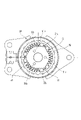
- FIG. 3 is a diagram showing the input side clutch in a neutral state.
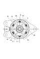
- FIG. 4 is a diagram showing the output side clutch in a neutral state.
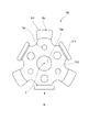
- FIG. 5 is a diagram of the operation bracket viewed from the operation lever side.
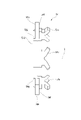
- FIG. 6 is a view of the operation bracket viewed from the VI direction in FIG.
- FIG. 7 is a sectional view of the clutch unit.
- FIG. 8 is a diagram showing overlapping of the operation plate, housing, and operation bracket.
- FIG. 1 is a side view showing a state in which the clutch unit according to this embodiment is applied to a vehicle seat lifter.
- a clutch unit 100 according to this embodiment is used in a vehicle seat 40.
- the vehicle seat 40 has a seating seat 40a, a backrest 40b, and a seat frame 40c.
- the clutch unit 100 is fixed to the seat frame 40c of the seating seat 40a.
- a vehicle seat lifter 41 is mounted on the vehicle seat 40 .
- the vehicle seat lifter 41 has a clutch unit 100 .
- the vehicle seat lifter 41 includes a sector gear 41f and a link mechanism.
- the clutch unit 100 has an operation lever 21 that is rotated in forward and reverse directions.
- a pinion gear 31 integrated with an output shaft member 30 rotated forward and reverse by the operation lever 21 meshes with a sector gear 41 f of a vehicle seat lifter 41 .
- the link mechanism includes a substantially vertically extending first link member 41c, a substantially vertically extending second link member 41d, and a substantially horizontally extending third link member 41e.
- the upper portion of the first link member 41c and the upper portion of the second link member 41d are rotatably connected to the seat frame 40c by shaft members 41c1 and 41d1, respectively.
- the lower portion of the first link member 41c and the lower portion of the second link member 41d are rotatably connected to the slide movable member 41b1 of the seat slide adjuster 41b by shaft members 41c2 and 41d2, respectively.
- One end of the third link member 41e is connected to the first link member 41c by the shaft member 41e1 above the shaft member 41c1.
- the other end of the third link member 41e is rotatably connected to the sector gear 41f by a shaft member 41e2.
- the operating lever 21 when the operating lever 21 is rotated clockwise (downward), the seating surface of the seating seat 40a is lowered by the operation opposite to that described above.
- the operating lever 21 rotates counterclockwise and returns to its original position (neutral position, neutral state).
- the clutch unit 100 brakes the rotation of the output shaft member 30 (pinion gear 31). Therefore, even if a vertical force is applied to the seating seat 40a, the seating seat 40a is prevented from moving in the vertical direction.
- FIG. 2 is an exploded perspective view of the clutch unit 100.
- the clutch unit 100 includes an operating lever 21 , an output shaft member 30 , an input side clutch 50 , an output side clutch 60 and a housing 11 .
- the input side clutch 50 is driven (actuated) by the operating lever 21 and transmits the rotation of the operating lever 21 to the output shaft member 30 .
- the output-side clutch 60 prevents rotation of the output shaft member 30 even if a vertical force is applied to the seating seat 40a.
- the input side clutch 50 and the output side clutch 60 are accommodated in the housing 11 .
- the housing 11 is a member that does not rotate when the operating lever 21 is operated.
- the output shaft member 30 is a shaft member extending from the lower left to the upper right in FIG.
- the output shaft member 30 is rotatable around a rotation axis X extending from the lower left to the upper right in FIG.
- rotational axis X direction means the direction in which the output shaft member 30 extends.
- the output shaft member 30 passes through the output side clutch 60 and the input side clutch 50 in this order from left to right in FIG.
- the lower left side in FIG. 2 may be called the output side
- the upper right side in FIG. 2 may be called the input side.
- the circumferential direction and the radial direction are defined with this rotation axis X as the center unless otherwise specified.
- the output shaft member 30 is provided with a pinion gear 31, a large-diameter cylindrical portion 32, a spline portion 33, and a small-diameter cylindrical portion 34 in this order from the output side to the input side.
- the pinion gear 31 is provided at the end of the output shaft member 30 on the output side.
- the large-diameter cylindrical portion 32 penetrates a metal bush 13 fixed to a cover member 14 of an output-side clutch 60, which will be described later.
- the small-diameter cylindrical portion 34 extends through an input-side inner ring member 51 and an input-side outer ring member 52 of an input-side clutch 50 , which will be described later, and the housing 11 .
- the spline portion 33 is spline-connected to an output-side inner ring member 61 of an output-side clutch 60, which will be described later.
- a stopper ring 36 is attached to the small-diameter cylindrical portion 34 of the output shaft member 30 .
- the stopper ring 36 has a cylindrical fitting portion 36a and a disc-shaped flange portion 36b located on the output side of the fitting portion 36a.
- the small-diameter cylindrical portion 34 of the output shaft member 30 is fitted into the fitting portion 36a.
- the flange portion 36 b prevents the later-described operation plate 22 , housing 11 , input side clutch 50 , and output side clutch 60 from slipping out of the output shaft member 30 .
- the housing 11 is a cup-shaped (bottomed cylindrical) member, and has a bottom surface 11a and a cylindrical portion 11b. Two fixed flanges 11c projecting in the radial direction are formed at the output-side end of the tubular portion 11b. A fixing bolt insertion hole 11d is provided in the fixing flange 11c.
- the housing 11 is fixed to the seat frame 40c by screwing a bolt (not shown) inserted into the fixing bolt insertion hole 11d into a screw hole of the seat frame 40c.
- the housing 11 may be fixed to the seat frame 40c by providing a crimped portion on the housing 11 and crimping the crimped portion to the seat frame 40c.
- the opening of the cup-shaped housing 11 is closed by a cover member 14 .
- an input side clutch 50 and an output side clutch 60 are accommodated in a space formed by the housing 11 and the cover member.
- the housing 11 is provided with a spring locking piece 11k.
- the spring locking piece 11k extends to the input side.
- a cylindrical bearing 11g is formed by burring at the center of the bottom surface 11a in the radial direction.
- the bearing 11g extends from the bottom surface 11a toward the input side.
- the bearing 11g rotatably supports the output shaft member 30 with respect to the housing 11.
- the bottom surface 11a is formed with three windows 11h each formed of an elongated arc-shaped hole and three protruding pieces 11i extending from the edges of the windows 11h toward the output side.
- the operation lever 21 is, for example, molded from synthetic resin and fixed to an operation plate 22, which will be described later.
- the operation lever 21 has a fixed portion 21a fixed to the operation plate 22 and a rod-shaped grip portion 21b extending radially outward from the fixed portion 21a.
- the operation plate 22 is provided between the housing 11 and the operation lever 21 in the rotation axis X direction.
- the operator grips the grip portion 21b of the operating lever 21 and rotates the operating lever 21 about the rotation axis X in forward and reverse directions, the operating plate 22 rotates forward and reverse integrally with the operating lever 21 .
- the operation plate 22 has an insertion hole 22a in the center in the radial direction. A small-diameter cylindrical portion 34 of the output shaft member 30 is inserted through the insertion hole 22a. Further, the operation plate 22 has three rectangular engagement holes 22b around the insertion hole 22a. A claw portion 54c of an operation bracket 54, which will be described later, is inserted into the engagement hole 22b, and the operation lever 21 rotates together with the operation bracket 54 via the operation plate 22. As shown in FIG.
- An operation piece portion 22d is provided on the outer peripheral edge of the operation plate 22.
- the operation piece portion 22d extends toward the output side.
- a return spring 23 is provided on the outer periphery of the housing 11 .
- the return spring 23 is a spring that returns the operating lever 21 and the operating plate 22 to their neutral positions when no operating force is applied to the operating lever 21 .
- the return spring 23 is, for example, an arcuate helical spring with both free ends 23a approaching each other. Both free ends 23 a of the return spring 23 are engaged with the spring engaging piece 11 k of the housing 11 and the operating piece 22 d of the operating plate 22 .
- the pair of free ends 23a of the return spring 23 are in contact with the spring locking piece 11k and the operating piece 22d. is supported in a neutral position.
- the operating plate 22 rotates together with the operating lever 21 with respect to the housing 11 .
- one free end portion 23a of the pair of free end portions 23a maintains the state of engagement with the spring locking piece 11k of the housing 11, and the other free end portion 23a engages the operation piece portion 22d of the operation plate 22. , and moves away from one free end 23a against the elastic restoring force of the return spring 23. As shown in FIG. Therefore, the return spring 23 bends, and a return force to the neutral position is applied.
- the input side clutch 50 includes an input side inner ring member 51, an input side outer ring member 52, an operation bracket 54 (an example of an operation member), an input side clutch roller 55 (an example of an input side transmission member), and an input side roller.
- a force spring 56 is provided.
- the input side inner ring member 51 is a cylindrical member extending in the rotation axis X direction.
- the input-side inner ring member 51 has an insertion hole 51a in the center through which the small-diameter cylindrical portion 34 of the output shaft member 30 is inserted.
- Three wedge cam portions 51c that protrude outward are provided at equal intervals on the outer peripheral edge of the input side inner ring member 51 .
- Three protrusions 51b are formed on the input-side surface of the input-side inner ring member 51 .
- the operation bracket 54 is a plate-like member.
- the operation bracket 54 has an insertion hole 54a through which the small-diameter cylindrical portion 34 of the output shaft member 30 is inserted, at the center in the radial direction.
- the operation bracket 54 also has three fitting holes 54b (see FIG. 2) into which the protrusions 51b of the input side inner ring member 51 are fitted.
- the input side inner ring member 51 and the operation bracket 54 which are separated from each other, rotate integrally with each other by the fitting structure between the projection 51b of the input side inner ring member 51 and the fitting hole 54b, and the rotation axis line is set. They are connected so as to be relatively movable in the X direction.
- the outer peripheral edge of the operation bracket 54 is provided with three claw portions 54c. These claw portions 54c pass through windows 11h formed in the bottom surface 11a of the housing 11 and are fitted into the engagement holes 22b of the operation plate 22. As shown in FIG. Thereby, the operation bracket 54 is connected to the operation plate 22 and is configured to rotate together with the operation plate 22 .
- the input side outer ring member 52 is a dish-shaped member.
- the input-side outer ring member 52 has a bottom portion 52b, an outer ring portion 52c, and a fixing portion 52d.
- the bottom portion 52b is a disk-shaped portion.
- An insertion hole 52a through which the small-diameter columnar portion 34 of the output shaft member 30 is inserted is provided in the radial center of the bottom portion 52b.
- the outer ring portion 52c is a cylindrical portion extending from the outer edge of the bottom portion 52b toward the input side.
- a bottom portion 52b is provided at the output-side end of the outer ring portion 52c.
- the fixing portion 52d is a protrusion that protrudes from the bottom portion 52b toward the output side.
- the fixed portion 52d is coupled with a release bracket 64 of the output-side clutch 60, which will be described later.
- FIG. 3 shows the input side clutch 50 in a neutral state.
- a gap is provided between the inner peripheral surface of the input side outer ring member 52 and the outer peripheral surface of the input side inner ring member 51 .
- the inner peripheral surface of the input side outer ring member 52 is a circular peripheral surface, while the outer peripheral surface of the input side inner ring member 51 is provided with three wedge cam portions 51c that bulge outward. Therefore, the gap between the inner peripheral surface of the input side outer ring member 52 and the outer peripheral surface of the input side inner ring member 51 is formed with wedge-shaped tapered portions at both ends in the radial direction.
- a protruding piece 11i of the housing 11 protrudes into this gap. When the input side inner ring member 51 is rotated by the operating lever 21, the protruding piece 11i restricts the movement of the input side clutch roller 55. As shown in FIG.
- the input side clutch 50 has six input side clutch rollers 55 and three input side roller biasing springs 56 .
- the input-side clutch roller 55 and the input-side roller biasing spring 56 are arranged between the outer peripheral surface of the input-side inner ring member 51 and the inner peripheral surface of the outer ring portion 52 c of the input-side outer ring member 52 .
- the input-side roller biasing spring 56 is arranged between the wedge cam portions 51c of the input-side inner ring member 51 in the circumferential direction.
- the input-side clutch rollers 55 are arranged in pairs on both sides of the wedge cam portion 51c of the input-side inner ring member 51 .
- a projecting piece 11 i of the housing 11 is arranged between the pair of input side clutch rollers 55 .
- the input-side roller biasing spring 56, the input-side clutch roller 55, the protruding piece 11i, and the input-side clutch roller 55 are arranged in this direction. are set in order.
- An input-side clutch roller 55 is provided in a wedge-shaped space between the input-side inner ring member 51 and the input-side outer ring member 52 that narrows in the clockwise direction.
- the outer peripheral surface of the input-side inner ring member 51 exerts a force that causes the input-side clutch roller 55 to bite into the wedge-shaped space that narrows clockwise. to act.
- the input-side clutch roller 55 applies a force having a radially outward pressing component and a counterclockwise pressing component to the inner peripheral surface of the input-side outer ring member 52 .
- the input-side clutch roller 55 applies a counterclockwise pushing force to the input-side outer ring member 52 .
- the input side outer ring member 52 rotates counterclockwise together with the input side clutch roller 55 .
- the output side clutch 60 includes an output side inner ring member 61, an output side outer ring member 62, a release bracket 64, an output side clutch roller 65, and an output side roller biasing spring 66. .
- the output side outer ring member 62 is a substantially cylindrical member.
- the output-side outer ring member 62 is provided coaxially with the output shaft member 30 and is rotatable relative to the output-side inner ring member 61 .
- the output-side outer ring member 62 is arranged on the outer peripheral side of the output-side inner ring member 61 .
- the output-side inner ring member 61 is provided coaxially with the output shaft member 30 and rotates together with the output shaft member 30 .
- the output side inner ring member 61 is a member having a smaller diameter than the output side outer ring member 62 .
- a plurality of grooves are provided on the inner peripheral surface of the output-side inner ring member 61 to form a spline portion 61a to which the spline portion 33 of the output shaft member 30 is coupled.
- Six protrusions 61b are formed on the input-side surface of the output-side inner ring member 61 (see FIG. 4).
- a dent which is a trace left when the protrusion 61b is formed by press working, can be seen on the surface on the output side.
- Six wedge cam portions 61c that protrude outward are formed at equal intervals on the outer peripheral portion of the output side inner ring member 61 .
- the release bracket 64 is a substantially disc-shaped member and is arranged closer to the input side than the output side inner ring member 61 .
- the release bracket 64 can transmit the force applied from the input side clutch 50 to the output side clutch roller 65 .
- the outer diameter of the release bracket 64 is formed larger than the outer diameter of the output side inner ring member 61 and smaller than the inner diameter of the output side outer ring member 62 .
- the release bracket 64 is a separate member from the output side inner ring member 61 , the output side outer ring member 62 , the input side inner ring member 51 and the input side outer ring member 52 .
- the release bracket 64 is formed with a plurality of first engagement holes 64a.
- the fixing portion 52d of the input side outer ring member 52 is inserted into the first engaging hole 64a. This allows the release bracket 64 to rotate together with the input side outer ring member 52 .
- the output side inner ring member 61 is provided with a protrusion 61b (see FIG. 4) that protrudes toward the input side.
- the release bracket 64 has a plurality of elongated holes 64b into which the protrusions 61b are respectively inserted. These elongated holes 64b are elongated holes extending in the circumferential direction.
- the protrusion 61b can be slightly displaced in the circumferential direction within the elongated hole 64b. In other words, the release bracket 64 and the output side inner ring member 61 are relatively rotatable within the range in which the protrusion 61b is displaced within the elongated hole 64b.
- the outer peripheral edge of the release bracket 64 is provided with six claw portions 64c extending toward the output side.
- the claw portion 64c is provided between the pair of output side clutch rollers 65. As shown in FIG.
- FIG. 4 shows the output side clutch 60 in the neutral state.
- a gap is provided between the inner peripheral surface of the output-side outer ring member 62 and the outer peripheral surface of the output-side inner ring member 61 .
- the inner peripheral surface of the output-side outer ring member 62 is a circular peripheral surface, while the outer peripheral surface of the output-side inner ring member 61 is provided with a wedge cam portion 61c that protrudes outward. Therefore, the gap between the inner peripheral surface of the output-side outer ring member 62 and the outer peripheral surface of the output-side inner ring member 61 is formed with wedge-shaped tapered portions at both ends in the radial direction.
- a claw portion 64c of the release bracket 64 protrudes into the gap between these portions. When the release bracket 64 is rotated, the claw portion 64c moves inside the gap.
- the output side clutch 60 has 12 output side clutch rollers 65 and 6 output side roller biasing springs 66 .
- the output-side clutch roller 65 and the output-side roller biasing spring 66 are arranged in a gap between the outer peripheral surface of the output-side inner ring member 61 and the inner peripheral surface of the output-side outer ring member 62 .
- the output-side clutch rollers 65 are arranged between the outer peripheral surface of the output-side inner ring member 61 and the inner peripheral surface of the output-side outer ring member 62 , so that the torque is generated between the output-side inner ring member 61 and the output-side outer ring member 62 .
- the peripheral surface of the cylindrical output side clutch roller 65 abuts on the claw portion 64 c of the release bracket 64 .
- the output-side roller biasing spring 66 is arranged between the wedge cam portions 61c of the output-side inner ring member 61 in the circumferential direction.
- the output-side clutch rollers 65 are arranged in pairs on both sides of the wedge cam portion 61 c of the output-side inner ring member 61 .
- a claw portion 64 c of the release bracket 64 is arranged between the pair of output side clutch rollers 65 .
- These output side clutch rollers 65 are biased toward the top of the wedge cam portion 61c by an output side roller biasing spring 66. As shown in FIG.
- a pawl portion 64c, an output-side clutch roller 65, an output-side roller biasing spring 66, and an output-side clutch roller 65 are arranged in this order.
- FIG. 4 shows the output side clutch 60 in a neutral state.
- the output side clutch roller 65 is urged by the output side roller urging spring 66 toward the top of the wedge cam portion 61c.
- the output-side clutch roller 65 bites into the wedge-shaped gap between the wedge cam portion 61 c of the output-side inner ring member 61 and the inner peripheral surface of the output-side outer ring member 62 .
- the gap in which the first output-side clutch roller 65a is positioned has a wedge shape tapering off in the counterclockwise direction.
- the first output side clutch roller 65 a is biased counterclockwise by an output side roller biasing spring 66 . Therefore, the first output side clutch roller 65a bites into the output side inner ring member 61 and the output side outer ring member 62 in the counterclockwise direction.
- the gap in which the second output-side clutch roller 65b is located has a wedge shape tapering off in the clockwise direction.
- the second output side clutch roller 65 b is biased clockwise by an output side roller biasing spring 66 . Therefore, the second output side clutch roller 65b bites into the output side inner ring member 61 and the output side outer ring member 62 in the clockwise direction.
- the output side outer ring member 62 is immovable with respect to the housing 11 here.
- the first output side clutch roller 65a and the second output side clutch roller 65b bite into both the output side inner ring member 61 and the output side outer ring member 62 in the counterclockwise and clockwise directions. Therefore, the output side inner ring member 61 and the output side outer ring member 62 cannot rotate. As a result, the output shaft member 30 spline-connected to the output side inner ring member 61 cannot rotate either.
- the output-side inner ring member 61 and the output-side outer ring member 62 are in a non-rotatable state.
- the output shaft member 30 never rotates.
- the vehicle seat 40 is fixed while its height is maintained.
- the release bracket 64 is coupled to the protrusion 61b of the output-side inner ring member 61 via the long hole 64b. Therefore, the release bracket 64 (1) first rotates counterclockwise in a state in which the output side inner ring member 61 does not rotate, and (2) the output side inner ring member rotates after the protrusion 61b contacts the edge of the elongated hole 64b. 61 rotates counterclockwise.
- the output side inner ring member 61 when the output side inner ring member 61 tries to rotate counterclockwise, the output side clutch roller that bites into the wedge-shaped space between the output side inner ring member 61 and the output side outer ring member 62 that narrows in the counterclockwise direction.
- the frictional force with the output side inner ring member 61 ceases to act, and the contact state with the output side inner ring member 61 is released.
- the output side inner ring member 61 can rotate relative to the output side outer ring member 62. become.
- the output side clutch 60 does not rotate the output shaft member 30 in a state in which no operating force acts on the operating lever 21 in the neutral state, and rotates the output shaft member 30 only in a state in which an operating force acts on the operating lever 21. It is configured to allow
- the clutch unit 100 of this embodiment is A clutch unit 100 used in a vehicle seat 40, an operating lever 21 rotatable around the rotation axis X; an output shaft member 30 that is rotatable about the rotation axis X and outputs an operation force input to the operation lever 21 to the vehicle seat 40; an operation plate 22 (operation member) that rotates together with the rotation of the operation lever 21; an input-side clutch 50 driven by the operating plate 22; an output side clutch 60 that transmits rotational torque of the input side clutch 50 to the output shaft member 30 and suppresses transmission of rotational torque from the output shaft member 30 to the input side clutch 50; and a bottomed cylindrical housing 11 that accommodates at least the input side clutch 50 .
- the input side clutch 50 is an input-side inner ring member 51 that rotates around the rotation axis X; an input-side outer ring member 52 that rotates around the rotation axis X; Input-side clutch rollers 55 (input-side intermediate rollers) 55 (input-side intermediate transmission member); and an operation bracket 54 that is fastened to the operation plate 22 and rotates around the rotation axis X together with the operation plate 22 .
- FIG. 5 is a view of the operation bracket 54 as seen from the operation lever 21 side.
- FIG. 6 is a view of the operation bracket 54 viewed from the VI direction in FIG.
- the operation bracket 54 is a plate-like member.
- the operation bracket 54 has an insertion hole 54a through which the small-diameter cylindrical portion 34 of the output shaft member 30 is inserted, at the center in the radial direction.
- the operation bracket 54 also has three fitting holes 54b (engagement portions) into which projections of the input-side inner ring member 51 are fitted.
- the input side inner ring member 51 and the operation bracket 54 which are separated from each other, rotate integrally with each other by the fitting structure between the projection 51b of the input side inner ring member 51 and the fitting hole 54b, and the rotation axis line is set. They are connected so as to be relatively movable in the X direction.
- Three claw portions 54 c are provided on the outer peripheral edge of the operation bracket 54 . These claw portions 54c pass through windows 11h formed in the bottom surface 11a of the housing 11 and are fitted into the engagement holes 22b of the operation plate 22. As shown in FIG. Thereby, the operation bracket 54 is connected to the operation plate 22 and is configured to rotate together with the operation plate 22 .
- the operation bracket 54 has a facing portion 54d and a sliding contact portion 54e.
- the facing portion 54d is a plate-like portion extending in the radial direction of the rotation axis X. As shown in FIG. A fitting hole 54b is provided in the facing portion 54d.
- a claw portion 54c and a sliding contact portion 54e are provided on the radial outer edge of the facing portion 54d.
- the operation bracket 54 is provided with three claw portions 54c and three sliding contact portions 54e. As shown in FIG. 6, the claw portion 54c extends from the outer edge of the facing portion 54d toward the input side.
- the tips of the claw portions 54c are bifurcated, and the tips extend in directions away from each other.
- the sliding contact portion 54e extends from the outer edge of the facing portion 54d toward the input side, and extends in the radial direction of the rotation axis X from its tip. In the rotation axis X direction, the tip of the sliding contact portion 54e is positioned closer to the input side than the facing portion 54d.
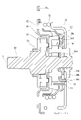
- FIG. 7 is a cross-sectional view of the clutch unit 100.
- the facing portion 54d faces the bottom surface 11a of the housing 11 with a gap therebetween.
- the claw portion 54 c extends from the facing portion 54 d toward the operation lever 21 , passes through a window portion 11 h (through hole) provided in the bottom surface 11 a of the housing 11 , and is fastened to the operation plate 22 .
- the sliding contact portion 54 e extends from the facing portion 54 d toward the bottom surface 11 a of the housing 11 and is in sliding contact with the bottom surface 11 a of the housing 11 .
- the facing portion 54d of the operation bracket 54 faces the bottom surface 11a of the housing 11 with a gap therebetween. does not contribute to friction between Of the pawl portion 54c (fastening portion) and the sliding contact portion 54e extending from the facing portion 54d toward the operation lever 21, the pawl portion 54c penetrates the window portion 11h (through hole) of the housing 11. 54c also does not contribute to the friction between the operating bracket 54 and the housing 11. Since only the sliding contact portion 54e is configured to be in sliding contact with the bottom surface 11a of the housing 11, sliding resistance between the housing 11 and the operation bracket 54 is suppressed.
- the sliding contact portion 54e extends toward the operation lever 21 from the radially outer end of the rotation axis X of the facing portion 54d. Since the sliding contact portion 54e is provided at a position away from the rotation axis X, the load acting on the sliding contact portion 54e can be reduced when a force that twists the operation lever 21 acts on the sliding contact portion 54e. can.
- the sliding contact portion 54e has a sliding contact surface portion 54f extending radially outward of the rotation axis X. As shown in FIG. In the illustrated example, the sliding contact portion 54e has a sliding contact surface portion 54f and a connecting portion 54g that connects the sliding contact surface portion 54f and the facing portion 54d. The sliding contact surface portion 54f is positioned closer to the operation lever 21 than the facing portion 54d in the rotation axis X direction. A surface of the sliding contact surface portion 54 f on the operation lever 21 side is in sliding contact with the bottom surface 11 a of the housing 11 .
- FIG. 8 is a diagram showing the overlapping of the operation plate 22, the housing 11, and the operation bracket 54. As shown in FIG.
- FIG. 8 shows how the three members overlap when the operating lever 21 is rotated to the maximum movable range. As shown in FIG. 8, a portion 54f1 of the sliding contact surface portion 54f overlaps the window portion 11h formed in the bottom surface 11a of the housing 11. As shown in FIG. 8,
- the clutch unit 100 of this embodiment only the part 54f1 of the sliding contact surface portion 54f overlaps the window portion 11h when the operating lever 21 is rotated to the maximum movable range, and the rest of the sliding contact surface portion 54f overlaps with the window portion 11h.
- the portion 54f2 overlaps the bottom surface 11a of the housing 11 without overlapping the window portion 11h.
- the portion 54f2 overlapping the bottom surface 11a of the housing 11 prevents the sliding contact portion 54e from coming off the window portion 11h.
- the portion 54f1 of the sliding surface portion 54f overlapping the window portion 11h comes to be in sliding contact with the bottom surface 11a.
- the sliding contact surface portion 54f is in sliding contact with the bottom surface 11a of the housing 11 outside the window portion 11h in the radial direction.
- the sliding contact surface portion 54f has a portion 54f3 radially outside the window portion 11h outside the portions 54f1 and 54f2 in the radial direction.
- the portion 54f3 allows the sliding contact surface portion 54f and the bottom surface 11a of the housing 11 to come into contact with each other at a position far from the rotation axis X, so that the force acting on the contact surfaces between the two when the operating lever 21 is operated can be reduced.
- the sliding contact surface portion 54f is in contact with the bottom surface 11a of the housing 11 outside the window portion 11h in the radial direction, the sliding contact surface portion 54f is always in contact with the bottom surface of the housing 11 regardless of the operation of the operating lever 21. 11a. Thereby, it is possible to more effectively prevent the operation bracket 54 from dropping out of the housing 11 through the window portion 11h.
- a plurality of sliding contact portions 54e are provided in the circumferential direction of the rotation axis X at regular intervals.
- three sliding contact portions 54e are provided in the circumferential direction of the rotation axis X at intervals of 120 degrees.
- the force acting between the operation bracket 54 and the bottom surface 11a of the housing 11 when the operation lever 21 is operated can be distributed and received by the three sliding contact portions 54e.
- the operation bracket 54 does not have directionality, workability when the operation bracket 54 is incorporated into the housing 11 is enhanced.
- the operation bracket 54 engages with the input side inner ring member 51 , but the operation bracket 54 may be configured to engage with the input side outer ring member 52 .
- the input side outer ring member 52 is arranged at a position closer to the bottom surface 11 a of the housing 11 than the input side inner ring member 51 is.
- the facing portion of the operation bracket faces the bottom surface of the housing with a gap therebetween, so the facing portion does not contribute to friction between the operation bracket and the housing.
- the fastening portion and the sliding portion extending from the opposing portion toward the output side clutch, the fastening portion passes through the through hole of the housing, so this fastening portion also does not contribute to the friction between the operation bracket and the housing. Since only the sliding portion is configured to be in sliding contact with the bottom surface of the housing, sliding resistance between the housing and the operation bracket is suppressed.
Landscapes
- Engineering & Computer Science (AREA)
- Mechanical Engineering (AREA)
- General Engineering & Computer Science (AREA)
- Aviation & Aerospace Engineering (AREA)
- Transportation (AREA)
- Mechanical Operated Clutches (AREA)
- Seats For Vehicles (AREA)
- Braking Arrangements (AREA)
Abstract
Description
車両用シートに用いられるクラッチユニットであって、
回転軸線回りに回転可能な操作レバーと、
前記回転軸線回りに回転可能であり、前記操作レバーに入力された操作力を車両用シートに出力する出力軸部材と、
前記操作レバーの回転とともに回転する操作部材と、
前記操作部材によって駆動される入力側クラッチと、
前記入力側クラッチの回転トルクを前記出力軸部材に伝達し、前記出力軸部材から前記入力側クラッチへの回転トルクの伝達を抑制する出力側クラッチと、
少なくとも前記入力側クラッチを収容する有底円筒状のハウジングと、を有し、
前記入力側クラッチは、
前記回転軸線回りに回転する入力側内輪部材と、
前記回転軸線回りに回転する入力側外輪部材と、
前記入力側内輪部材と前記入力側外輪部材との間に回転可能に設けられ、前記入力側外輪部材と前記入力側内輪部材との間で回転トルクを伝達する入力側中間伝達部材と、
前記操作部材と締結され、前記操作部材とともに前記回転軸線回りに回転する操作ブラケットと、を有し、
前記操作ブラケットは、
前記入力側内輪部材または前記入力側外輪部材と係合する係合部と、
前記ハウジングの底面と隙間を隔てて向かい合う対向部と、
前記対向部から前記操作部材に向かって延びて、前記ハウジングの前記底面に設けられた貫通孔を貫通して前記操作部材と締結される締結部と、
前記対向部から前記ハウジングの前記底面に向かって延びて、前記ハウジングの前記底面に摺接する摺接部と、を有する、クラッチユニット。
そして、操作レバー21を開放した状態では、クラッチユニット100によって出力軸部材30(ピニオンギヤ31)の回転にブレーキが掛けられる。このため、着座シート40aに上下方向の力が加わっても着座シート40aの上下方向への移動が阻止される。
次に、本実施形態に係るクラッチユニット100を説明する。以下に説明するクラッチユニット100の構成部品は、特に断らない限り基本的に金属製である。
カップ状のハウジング11の開口はカバー部材14によって閉塞されている。本実施形態において、ハウジング11とカバー部材とによって形成される空間内には、入力側クラッチ50と、出力側クラッチ60とが収容されている。
入力側クラッチ50は、入力側内輪部材51と、入力側外輪部材52と、操作ブラケット54(操作部材の一例)と、入力側クラッチコロ55(入力側伝達部材の一例)と、入力側コロ付勢バネ56を備えている。
入力側内輪部材51の外周縁には、外方へ膨出する3つの楔カム部51cが等間隔に設けられている。入力側内輪部材51の入力側の面には、3つの突起部51bが形成されている。
図3に示すように、入力側外輪部材52の内周面と入力側内輪部材51の外周面との間には、隙間が設けられている。入力側外輪部材52の内周面は円周面である一方で、入力側内輪部材51の外周面には外方へ膨出する3つの楔カム部51cが設けられている。このため、入力側外輪部材52の内周面と入力側内輪部材51の外周面との間の隙間には、径方向の両端が楔状に先細りになった部分が形成されている。この隙間に、ハウジング11の突出片11iが突出している。操作レバー21によって入力側内輪部材51が回転されると、突出片11iが入力側クラッチコロ55の動きを規制する。
図3に示すように、中立状態において、入力側クラッチ50では、入力側クラッチコロ55が入力側コロ付勢バネ56に接触しており、入力側クラッチコロ55が入力側コロ付勢バネ56によって楔カム部51cの頂部へ向かって付勢されている。このため、中立状態において、入力側クラッチコロ55が入力側内輪部材51と入力側外輪部材52とに食い込んでいる。
図2に戻り、出力側クラッチ60は、出力側内輪部材61と、出力側外輪部材62と、解除ブラケット64と、出力側クラッチコロ65と、出力側コロ付勢バネ66と、を備えている。
図4は、中立状態における出力側クラッチ60を示している。図4に示すように、中立状態において、出力側クラッチ60では、出力側クラッチコロ65が出力側コロ付勢バネ66によって楔カム部61cの頂部へ向かって付勢されている。これにより、出力側クラッチコロ65が、出力側内輪部材61における楔カム部61cと出力側外輪部材62の内周面との間の楔状の隙間に食い込んでいる。
第一出力側クラッチコロ65aが位置している隙間は、反時計方向に向かって先細りの楔形状である。第一出力側クラッチコロ65aは、出力側コロ付勢バネ66によって反時計方向に付勢されている。このため、第一出力側クラッチコロ65aは、反時計方向に出力側内輪部材61と出力側外輪部材62とに食い込んでいる。
第二出力側クラッチコロ65bが位置している隙間は、時計方向に向かって先細りの楔形状である。第二出力側クラッチコロ65bは、出力側コロ付勢バネ66によって時計方向に付勢されている。このため、第二出力側クラッチコロ65bは、時計方向に出力側内輪部材61と出力側外輪部材62とに食い込んでいる。
操作レバー21が反時計方向に回転されると、上述したように入力側クラッチ50の入力側外輪部材52が反時計方向に回転する。入力側外輪部材52は解除ブラケット64とスプライン結合されている。このため、操作レバー21が反時計方向に回転されると、解除ブラケット64も反時計方向に回転する。
また、出力側内輪部材61が反時計方向に回転しようとすると、出力側内輪部材61と出力側外輪部材62との間の反時計方向に幅狭となる楔状空間に食い込んでいた出力側クラッチコロ65は、出力側内輪部材61との間の摩擦力が作用しなくなり、出力側内輪部材61との当接状態が解除される。
このように、出力側クラッチコロ65の出力側内輪部材61と出力側外輪部材62との当接状態が解除された状態では、出力側内輪部材61は出力側外輪部材62に対して相対回転可能になる。
車両用シート40に用いられるクラッチユニット100であって、
回転軸線X回りに回転可能な操作レバー21と、
回転軸線X回りに回転可能であり、操作レバー21に入力された操作力を車両用シート40に出力する出力軸部材30と、
操作レバー21の回転とともに回転する操作板22(操作部材)と、
操作板22によって駆動される入力側クラッチ50と、
入力側クラッチ50の回転トルクを出力軸部材30に伝達し、出力軸部材30から入力側クラッチ50への回転トルクの伝達を抑制する出力側クラッチ60と、
少なくとも入力側クラッチ50を収容する有底円筒状のハウジング11と、を有する。
入力側クラッチ50は、
回転軸線X回りに回転する入力側内輪部材51と、
回転軸線X回りに回転する入力側外輪部材52と、
入力側内輪部材51と入力側外輪部材52との間に回転可能に設けられ、入力側外輪部材52と入力側内輪部材51との間で回転トルクを伝達する入力側クラッチコロ55(入力側中間伝達部材)と、
操作板22と締結され、操作板22とともに回転軸線X回りに回転する操作ブラケット54と、を有する。
図5は、操作ブラケット54を操作レバー21側から見た図である。図6は、操作ブラケット54を図5のVI方向から見た図である。
前述したように、操作ブラケット54は、板状の部材である。操作ブラケット54は、径方向における中心に出力軸部材30の小径円柱部34が挿通される挿通孔54aを有している。また、操作ブラケット54は、入力側内輪部材51の突起部が嵌合される3つの嵌合孔54b(係合部)を有している。入力側内輪部材51の突起部51bと嵌合孔54bとの嵌合構造によって、それぞれ別体の入力側内輪部材51と操作ブラケット54とは、互いに一体的に回転するように、かつ、回転軸線X方向に相対移動可能に連結されている。
対向部54dは、回転軸線Xの径方向に延びる板状の部位である。この対向部54dに嵌合孔54bが設けられている。対向部54dの径方向の外縁に爪部54cと摺接部54eが設けられている。図示の例では、3つの爪部54cおよび3つの摺接部54eが操作ブラケット54に設けられている。
図6に示すように爪部54cは、対向部54dの外縁から入力側に向かって延びている。図示の例では、爪部54cの先端は二股形状とされており、それらの先端は互いに離間する方向に延びている。
摺接部54eは対向部54dの外縁から入力側に向かって延び、その先で回転軸線Xの径方向に延びている。回転軸線X方向において、摺接部54eの先端部は対向部54dよりも入力側に位置している。
回転軸線Xから離れた位置に摺接部54eが設けられているため、操作レバー21をこじるような力が摺接部54eに作用したとき、摺接部54eに作用する荷重を低減することができる。
摺接部54eは、回転軸線Xの径方向の外側に延出する摺接面部54fを有する。
図示の例では、摺接部54eは、摺接面部54fと、摺接面部54fと対向部54dとを接続する接続部54gとを有している。摺接面部54fは対向部54dよりも回転軸線X方向において操作レバー21側に位置している。摺接面部54fの操作レバー21側の面がハウジング11の底面11aに摺接する。
図8は、操作板22、ハウジング11、操作ブラケット54の重なりを示す図である。図8では、操作レバー21を最大可動範囲まで回転させた状態における3部材の重なり具合を示している。図8に示したように、摺接面部54fの一部54f1が、ハウジング11の底面11aに形成された窓部11hと重なっている。
また、図8に示した状態から操作レバー21から手を離し初期位置まで戻ると、窓部11hと重なっていた摺接面部54fの一部54f1は底面11aと摺接するようになる。本実施形態とは異なり、操作レバーを初期位置から最大可動範囲まで回転させる間中、常に、貫通孔に重ならない位置にのみ摺接面を設ける場合(窓部に摺接面部の一部を重ねるという技術思想がない場合)には、摺接面を小さくする、ハウジングを大きくする、窓部を小さくする、操作ブラケットの可動範囲を小さくする(摺接面部が各窓部の間でのみ回転)といった設計上の制約が生じる。このような場合はクラッチユニットが大型化したり、操作レバーの操作角が小さくなってしまうといった不都合が生じる。本実施形態のクラッチユニット100によれば、窓部11hと重なる位置にも摺接面部54f(54f1)が設けられているため、クラッチユニット100の大型化を抑制でき、また、大きな操作角を確保できている。
部位54f3によって、回転軸線Xから遠い位置で摺接面部54fとハウジング11の底面11aとが接することができるため、操作レバー21の操作時に両者の接触面に作用する力を低減できる。また、摺接面部54fの部位54f3が窓部11hよりも径方向の外側でハウジング11の底面11aと接しているので、操作レバー21の操作に関わらず、常に摺接面部54fがハウジング11の底面11aに接することができる。これにより、操作ブラケット54が窓部11hからハウジング11の外に脱落することをより効果的に防止できる。
11a 底面
13 メタルブッシュ
21 操作レバー
22 操作板(操作部材)
22b 係合孔
30 出力軸部材
31 ピニオンギヤ
32 大径円柱部
33 スプライン部
34 小径円柱部
36 ストッパリング
40 車両用シート
50 入力側クラッチ
51 入力側内輪部材
51b 突起部
52 入力側外輪部材
54 操作ブラケット
54a 挿通孔
54b 嵌合孔(係合部)
54c 爪部(締結部)
54d 対向部
54e 摺接部
54f 摺接面部
54g 接続部
55 入力側クラッチコロ(入力側中間伝達部材)
56 入力側コロ付勢バネ
60 出力側クラッチ
61 出力側内輪部材
62 出力側外輪部材
64 解除ブラケット
65 出力側クラッチコロ
66 出力側コロ付勢バネ
70 ロック部材
100 クラッチユニット
X 回転軸線
Claims (5)
- 車両用シートに用いられるクラッチユニットであって、
回転軸線回りに回転可能な操作レバーと、
前記回転軸線回りに回転可能であり、前記操作レバーに入力された操作力を車両用シートに出力する出力軸部材と、
前記操作レバーの回転とともに回転する操作部材と、
前記操作部材によって駆動される入力側クラッチと、
前記入力側クラッチの回転トルクを前記出力軸部材に伝達し、前記出力軸部材から前記入力側クラッチへの回転トルクの伝達を抑制する出力側クラッチと、
少なくとも前記入力側クラッチを収容する有底円筒状のハウジングと、を有し、
前記入力側クラッチは、
前記回転軸線回りに回転する入力側内輪部材と、
前記回転軸線回りに回転する入力側外輪部材と、
前記入力側内輪部材と前記入力側外輪部材との間に回転可能に設けられ、前記入力側外輪部材と前記入力側内輪部材との間で回転トルクを伝達する入力側中間伝達部材と、
前記操作部材と締結され、前記操作部材とともに前記回転軸線回りに回転する操作ブラケットと、を有し、
前記操作ブラケットは、
前記入力側内輪部材または前記入力側外輪部材と係合する係合部と、
前記ハウジングの底面と隙間を隔てて向かい合う対向部と、
前記対向部から前記操作部材に向かって延びて、前記ハウジングの前記底面に設けられた貫通孔を貫通して前記操作部材と締結される締結部と、
前記対向部から前記ハウジングの前記底面に向かって延びて、前記ハウジングの前記底面に摺接する摺接部と、を有する、クラッチユニット。 - 前記摺接部は、前記対向部における前記回転軸線の径方向の外端部から前記ハウジングの前記底面側に延びている、請求項1に記載のクラッチユニット。
- 前記摺接部は、前記回転軸線の径方向の外側に延出する摺接面を有し、
前記操作レバーを最大可動範囲まで回動させた状態において、前記摺接面の一部が前記ハウジングの前記底面に形成された前記貫通孔と重なっている、請求項1に記載のクラッチユニット。 - 前記摺接面は、前記貫通孔よりも径方向の外側で前記ハウジングの前記底面と摺接する、請求項3に記載のクラッチユニット。
- 複数の前記摺接部は、前記回転軸線の周方向に等間隔で設けられている、請求項1に記載のクラッチユニット。
Priority Applications (2)
| Application Number | Priority Date | Filing Date | Title |
|---|---|---|---|
| EP22745918.7A EP4286705A4 (en) | 2021-01-29 | 2022-01-26 | CLUTCH UNIT |
| US18/043,817 US12097787B2 (en) | 2021-01-29 | 2022-01-26 | Clutch unit |
Applications Claiming Priority (2)
| Application Number | Priority Date | Filing Date | Title |
|---|---|---|---|
| JP2021013325A JP7482805B2 (ja) | 2021-01-29 | 2021-01-29 | クラッチユニット |
| JP2021-013325 | 2021-01-29 |
Publications (1)
| Publication Number | Publication Date |
|---|---|
| WO2022163699A1 true WO2022163699A1 (ja) | 2022-08-04 |
Family
ID=82653420
Family Applications (1)
| Application Number | Title | Priority Date | Filing Date |
|---|---|---|---|
| PCT/JP2022/002889 Ceased WO2022163699A1 (ja) | 2021-01-29 | 2022-01-26 | クラッチユニット |
Country Status (4)
| Country | Link |
|---|---|
| US (1) | US12097787B2 (ja) |
| EP (1) | EP4286705A4 (ja) |
| JP (1) | JP7482805B2 (ja) |
| WO (1) | WO2022163699A1 (ja) |
Cited By (1)
| Publication number | Priority date | Publication date | Assignee | Title |
|---|---|---|---|---|
| CN116221300A (zh) * | 2023-02-27 | 2023-06-06 | 中国石油大学(北京) | 棘轮机构 |
Citations (6)
| Publication number | Priority date | Publication date | Assignee | Title |
|---|---|---|---|---|
| US20180001794A1 (en) * | 2016-06-29 | 2018-01-04 | Das Co., Ltd. | Pumping apparatus for vehicle seat |
| JP2018059596A (ja) * | 2016-10-07 | 2018-04-12 | シロキ工業株式会社 | 車両用クラッチユニット |
| WO2019230847A1 (ja) * | 2018-05-31 | 2019-12-05 | シロキ工業株式会社 | 車両用クラッチユニット |
| WO2019230839A1 (ja) * | 2018-05-31 | 2019-12-05 | シロキ工業株式会社 | 車両用クラッチユニット |
| JP2020069852A (ja) | 2018-10-30 | 2020-05-07 | トヨタ紡織株式会社 | リフタ装置 |
| JP2021013325A (ja) | 2019-07-11 | 2021-02-12 | 日本製紙株式会社 | 菓子類および菓子類の製造方法 |
Family Cites Families (6)
| Publication number | Priority date | Publication date | Assignee | Title |
|---|---|---|---|---|
| JP5717283B2 (ja) * | 2011-03-09 | 2015-05-13 | Ntn株式会社 | クラッチユニット |
| JP6712700B2 (ja) | 2016-08-22 | 2020-06-24 | リイマジンコンサルティング株式会社 | 共済の運用するための方法、プログラム及びシステム |
| JP6738691B2 (ja) * | 2016-08-30 | 2020-08-12 | Ntn株式会社 | クラッチユニット |
| JP2019032070A (ja) * | 2017-08-09 | 2019-02-28 | シロキ工業株式会社 | 車両用クラッチユニット |
| JP2020046018A (ja) * | 2018-09-20 | 2020-03-26 | シロキ工業株式会社 | クラッチユニット |
| JP2020046017A (ja) * | 2018-09-20 | 2020-03-26 | シロキ工業株式会社 | クラッチユニット |
-
2021
- 2021-01-29 JP JP2021013325A patent/JP7482805B2/ja active Active
-
2022
- 2022-01-26 WO PCT/JP2022/002889 patent/WO2022163699A1/ja not_active Ceased
- 2022-01-26 EP EP22745918.7A patent/EP4286705A4/en not_active Withdrawn
- 2022-01-26 US US18/043,817 patent/US12097787B2/en active Active
Patent Citations (6)
| Publication number | Priority date | Publication date | Assignee | Title |
|---|---|---|---|---|
| US20180001794A1 (en) * | 2016-06-29 | 2018-01-04 | Das Co., Ltd. | Pumping apparatus for vehicle seat |
| JP2018059596A (ja) * | 2016-10-07 | 2018-04-12 | シロキ工業株式会社 | 車両用クラッチユニット |
| WO2019230847A1 (ja) * | 2018-05-31 | 2019-12-05 | シロキ工業株式会社 | 車両用クラッチユニット |
| WO2019230839A1 (ja) * | 2018-05-31 | 2019-12-05 | シロキ工業株式会社 | 車両用クラッチユニット |
| JP2020069852A (ja) | 2018-10-30 | 2020-05-07 | トヨタ紡織株式会社 | リフタ装置 |
| JP2021013325A (ja) | 2019-07-11 | 2021-02-12 | 日本製紙株式会社 | 菓子類および菓子類の製造方法 |
Non-Patent Citations (1)
| Title |
|---|
| See also references of EP4286705A4 |
Cited By (1)
| Publication number | Priority date | Publication date | Assignee | Title |
|---|---|---|---|---|
| CN116221300A (zh) * | 2023-02-27 | 2023-06-06 | 中国石油大学(北京) | 棘轮机构 |
Also Published As
| Publication number | Publication date |
|---|---|
| US20240116405A1 (en) | 2024-04-11 |
| EP4286705A1 (en) | 2023-12-06 |
| US12097787B2 (en) | 2024-09-24 |
| EP4286705A4 (en) | 2024-07-24 |
| JP7482805B2 (ja) | 2024-05-14 |
| JP2022116904A (ja) | 2022-08-10 |
Similar Documents
| Publication | Publication Date | Title |
|---|---|---|
| JP6745159B2 (ja) | 車両用クラッチユニット | |
| US10927903B2 (en) | Clutch unit | |
| EP3805586B1 (en) | Clutch unit for vehicle | |
| CN107917151B (zh) | 用于车辆的离合器单元 | |
| EP3805587B1 (en) | Clutch unit for vehicle | |
| JP6745188B2 (ja) | 車両用クラッチユニット | |
| JP6653565B2 (ja) | 車両用クラッチユニット | |
| US12202388B2 (en) | Clutch unit | |
| JP2022116904A (ja) | クラッチユニット | |
| JP2019032070A (ja) | 車両用クラッチユニット | |
| JP2020046018A (ja) | クラッチユニット | |
| WO2022163706A1 (ja) | クラッチユニット | |
| JP2020034083A (ja) | クラッチユニット | |
| WO2017104385A1 (ja) | 車両用クラッチユニット | |
| JP2020046016A (ja) | クラッチユニット | |
| JP7291101B2 (ja) | 車両用クラッチユニット | |
| JP2020032780A (ja) | 車両用クラッチユニット |
Legal Events
| Date | Code | Title | Description |
|---|---|---|---|
| 121 | Ep: the epo has been informed by wipo that ep was designated in this application |
Ref document number: 22745918 Country of ref document: EP Kind code of ref document: A1 |
|
| WWE | Wipo information: entry into national phase |
Ref document number: 2022745918 Country of ref document: EP |
|
| NENP | Non-entry into the national phase |
Ref country code: DE |
|
| ENP | Entry into the national phase |
Ref document number: 2022745918 Country of ref document: EP Effective date: 20230829 |
|
| WWW | Wipo information: withdrawn in national office |
Ref document number: 2022745918 Country of ref document: EP |