WO2022168538A1 - ステータ - Google Patents
ステータ Download PDFInfo
- Publication number
- WO2022168538A1 WO2022168538A1 PCT/JP2022/000588 JP2022000588W WO2022168538A1 WO 2022168538 A1 WO2022168538 A1 WO 2022168538A1 JP 2022000588 W JP2022000588 W JP 2022000588W WO 2022168538 A1 WO2022168538 A1 WO 2022168538A1
- Authority
- WO
- WIPO (PCT)
- Prior art keywords
- phase
- busbar
- stator core
- bus bar
- stator
- Prior art date
- Legal status (The legal status is an assumption and is not a legal conclusion. Google has not performed a legal analysis and makes no representation as to the accuracy of the status listed.)
- Ceased
Links
Images




Classifications
-
- H—ELECTRICITY
- H02—GENERATION; CONVERSION OR DISTRIBUTION OF ELECTRIC POWER
- H02K—DYNAMO-ELECTRIC MACHINES
- H02K3/00—Details of windings
- H02K3/46—Fastening of windings on the stator or rotor structure
- H02K3/52—Fastening salient pole windings or connections thereto
- H02K3/521—Fastening salient pole windings or connections thereto applicable to stators only
- H02K3/522—Fastening salient pole windings or connections thereto applicable to stators only for generally annular cores with salient poles
-
- H—ELECTRICITY
- H02—GENERATION; CONVERSION OR DISTRIBUTION OF ELECTRIC POWER
- H02K—DYNAMO-ELECTRIC MACHINES
- H02K3/00—Details of windings
- H02K3/46—Fastening of windings on the stator or rotor structure
- H02K3/52—Fastening salient pole windings or connections thereto
- H02K3/521—Fastening salient pole windings or connections thereto applicable to stators only
-
- H—ELECTRICITY
- H02—GENERATION; CONVERSION OR DISTRIBUTION OF ELECTRIC POWER
- H02K—DYNAMO-ELECTRIC MACHINES
- H02K1/00—Details of the magnetic circuit
- H02K1/06—Details of the magnetic circuit characterised by the shape, form or construction
- H02K1/12—Stationary parts of the magnetic circuit
- H02K1/16—Stator cores with slots for windings
-
- H—ELECTRICITY
- H02—GENERATION; CONVERSION OR DISTRIBUTION OF ELECTRIC POWER
- H02K—DYNAMO-ELECTRIC MACHINES
- H02K3/00—Details of windings
- H02K3/04—Windings characterised by the conductor shape, form or construction, e.g. with bar conductors
- H02K3/28—Layout of windings or of connections between windings
-
- H—ELECTRICITY
- H02—GENERATION; CONVERSION OR DISTRIBUTION OF ELECTRIC POWER
- H02K—DYNAMO-ELECTRIC MACHINES
- H02K3/00—Details of windings
- H02K3/32—Windings characterised by the shape, form or construction of the insulation
- H02K3/38—Windings characterised by the shape, form or construction of the insulation around winding heads, equalising connectors, or connections thereto
-
- H—ELECTRICITY
- H02—GENERATION; CONVERSION OR DISTRIBUTION OF ELECTRIC POWER
- H02K—DYNAMO-ELECTRIC MACHINES
- H02K2203/00—Specific aspects not provided for in the other groups of this subclass relating to the windings
- H02K2203/09—Machines characterised by wiring elements other than wires, e.g. bus rings, for connecting the winding terminations
-
- H—ELECTRICITY
- H02—GENERATION; CONVERSION OR DISTRIBUTION OF ELECTRIC POWER
- H02K—DYNAMO-ELECTRIC MACHINES
- H02K9/00—Arrangements for cooling or ventilating
- H02K9/22—Arrangements for cooling or ventilating by solid heat conducting material embedded in, or arranged in contact with, the stator or rotor, e.g. heat bridges
- H02K9/223—Heat bridges
Definitions
- the present disclosure relates to a stator of a motor.
- a stator described in JP-A-2014-11937 has a stator core and a plurality of coils attached to the stator core.
- the coil is made of a rectangular conductor, and has a winding portion wound around the teeth of the stator core, a terminal portion drawn from the outer end portion of the winding portion, and a busbar portion drawn from the inner end portion of the winding portion. have.
- the outer end portions of the winding portions are arranged on the root side of the teeth, and the terminal portions drawn out from the outer end portions are arranged on the outer peripheral side of the yoke of the stator core.
- the inner ends of the winding portions are arranged on the tip side of the teeth, and the busbar portion is routed from the inner ends to the outer peripheral side of the yoke. This busbar portion is joined to the end portion of another coil.
- the motor described in JP-A-2020-145916 includes a plurality of stator members and busbar members.
- a coil is wound around each of the plurality of stator members, which are arranged in a ring when viewed in the axial direction of the motor. Both ends of each coil are pulled out to the outer peripheral side of the stator member and joined to the busbar member.
- the busbar member includes an annular base portion and connection terminals extending from the base portion toward the outer periphery of the stator member. Both ends of the coil are inserted into two recesses formed in the connection terminals. It is
- both ends of each coil are pulled out to the outer peripheral side of the yoke.
- a thick wire coil such a configuration requires a step of winding the end of the coil wound on the tip end side of the tooth to the outer peripheral side of the yoke after the step of winding the coil around the tooth.
- factors such as an increase in manufacturing cost, a decrease in workability, and a deterioration in the dimensional accuracy of the coil, for example.
- the present disclosure aims to obtain a stator that eliminates the need for the process of pulling the ends of the coils wound to the tip end side of the teeth to the outer peripheral side of the yoke.
- the stator of the first aspect includes a stator core having a yoke and a plurality of teeth, each wound around the plurality of teeth, one end of each of which is disposed on the root side of each of the teeth, and the other end of each of which is disposed on each of the teeth. a plurality of coils disposed on the distal end side of the stator core; a first bus bar extending from a first extending portion toward the root side of each of the teeth and having a plurality of first joint portions to which the one ends of the coils are joined; and arranged axially with respect to the stator core.
- a second bus bar having a plurality of second joints to which parts are joined.
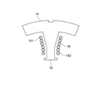
- coils are wound around the plurality of teeth of the stator core.
- One end of each coil is arranged on the root side of each tooth, and the other end of each coil is arranged on the tip side of each tooth.
- a first bus bar is arranged on one side of the stator core in the axial direction.
- the first bus bar has a first extending portion extending in the circumferential direction of the stator core along the yoke of the stator core.
- a plurality of first joint portions extend from the first extension portion to the root side of each tooth.
- One end of each coil is joined to the plurality of first joints.
- a second bus bar is arranged on one side or the other side of the stator core in the axial direction.
- the second bus bar has a second extending portion extending in the circumferential direction of the stator core along the yoke.
- a plurality of second joint portions extend from the second extension portion toward the tip side of each tooth. The other end of each coil is joined to the plurality of second joints. In this way, since the second joint portion of the second bus bar extends toward the tip side of the tooth and is joined to the other end portion of each coil, the other end portion of each coil wound toward the tip side of the tooth is connected to the yoke. The process of pulling it around to the outer peripheral side of the is unnecessary.
- the second busbar is arranged on the other side in the axial direction with respect to the stator core.
- the first busbar is arranged on one side in the axial direction with respect to the stator core, and the second busbar is arranged on the other side in the axial direction with respect to the stator core.
- the first bus bar and the second bus bar are arranged separately on both sides in the axial direction with respect to the stator core, so that each bus bar can be easily cooled.
- a stator according to a third aspect is, in the second aspect, a first insulator that has insulating properties and thermal conductivity and holds the first extension portion, has insulating properties and thermal conductivity, and has the first insulator that holds the first extending portion. and a second insulator holding the two extensions.
- the first extending portion of the first bus bar arranged on one side in the axial direction with respect to the stator core is held by the first insulator having insulating properties and thermal conductivity.
- a second extending portion of the second bus bar arranged on the other side in the axial direction with respect to the stator core is held by a second insulator having insulating properties and thermal conductivity. The heat of the first bus bar and the second bus bar can be radiated via these first insulator and second insulator.
- the second busbar is arranged on one side in the axial direction with respect to the stator core.
- the first busbar and the second busbar are arranged on one side in the axial direction with respect to the stator core.
- the unit of the first bus bar and the second bus bar can be integrated, and the manufacturing cost can be reduced.
- each bus bar and each coil can be joined only on one side of the stator core in the axial direction, the assembly process and setup of the stator can be simplified.
- the stator of the fifth aspect in the fourth aspect, includes an insulator that has insulating properties and thermal conductivity and holds the first extending portion and the second extending portion.
- the first bus bar and the second bus bar arranged on one side of the stator core in the axial direction are collectively held by an insulator having insulating properties and thermal conductivity.
- the heat of the first bus bar and the second bus bar can be dissipated through this insulator.
- a sixth aspect of the stator is any one of the first to fifth aspects, wherein the plurality of coils includes a U-phase coil, a V-phase coil and a W-phase coil, and
- the first busbar includes a U-phase busbar, a V-phase busbar, and a W-phase busbar, and the U-phase busbar, the V-phase busbar, and the W-phase busbar are each connected to a three-phase power supply. It has a terminal portion, a V-phase terminal portion, and a W-phase terminal portion.
- one ends of the U-phase coil, the V-phase coil, and the W-phase coil are joined to the U-phase busbar, the V-phase busbar, and the W-phase busbar included in the first busbar.
- the other ends of the phase coil and the W-phase coil are connected to the second bus bar.
- a U-phase terminal portion, a V-phase terminal portion, and a W-phase terminal portion of the U-phase bus bar, the V-phase bus bar, and the W-phase bus bar are connected to a three-phase power source. This allows the stator to function as a stator for a three-phase motor.
- stator according to the present disclosure eliminates the need for the process of pulling the ends of the coil wound on the tip end side of the tooth to the outer circumference side of the yoke.
- FIG. 1 is a perspective view showing a stator according to a first embodiment; FIG. It is a top view showing the stator concerning a 1st embodiment.
- FIG. 3 is a cross-sectional view showing a cut surface along line F3-F3 of FIG. 2; 1 is an exploded perspective view showing a stator according to a first embodiment; FIG. It is a sectional view showing a partial composition of a stator concerning a 1st embodiment.
- FIG. 3 is a perspective view showing a part of the busbar unit of the stator according to the first embodiment; It is a perspective view showing a stator according to a second embodiment.
- FIG. 4 is a cross-sectional view similar to FIG. 3 showing a stator according to a second embodiment; FIG.
- FIG. 8 is an exploded perspective view showing a stator according to a second embodiment
- FIG. 8 is a perspective view showing part of a first busbar unit of a stator according to a second embodiment
- FIG. 11 is a perspective view showing part of a second busbar unit of a stator according to a second embodiment
- FIG. 10 A stator 10 according to a first embodiment of the present disclosure will be described below with reference to FIGS. 1 to 5.
- FIG. 1 the scale of drawing is changed suitably.
- some reference numerals may be omitted for the purpose of making the drawings easier to read.
- the stator 10 is an armature (stator) including a stator core 12, a plurality of (here, 24) coils 18, and a busbar unit 20. be.
- the stator core 12 , the plurality of coils 18 and the busbar unit 20 are housed inside a cylindrical case 28 .
- a rotor (not shown) is arranged inside the stator 10 to constitute an inner rotor type motor (rotary electric machine). This motor is, for example, a three-phase motor.
- the stator core 12 is constructed by laminating a plurality of iron core pieces made of electromagnetic steel sheets.
- the stator core 12 is formed in an annular shape and has a yoke 14 and a plurality of (here, 24) teeth 16 .
- the yoke 14 has a cylindrical shape.
- the plurality of teeth 16 are formed to protrude radially inward of the stator core 12 from the inner peripheral surface of the yoke 14 .
- a plurality of teeth 16 are formed side by side at regular intervals in the circumferential direction of the stator core 12 , and slots (reference numerals omitted) are formed between the plurality of teeth 16 .
- the stator 10 is fitted inside the case 28 .
- the numbers of poles and slots of the stator 10 shown in FIGS. 1 to 4 are merely examples, and are not limited to these.
- a plurality of coils 18 are spirally wound around a plurality of teeth 16 respectively.
- An insulator such as an insulator, insulating paper, or varnish is interposed between each coil 18 and each tooth 16 .
- Each coil 18 is configured such that a wire made of, for example, copper, aluminum, silver, or an alloy wire thereof is coated with an insulator such as enamel.
- this element wire is a round wire here, it may be a rectangular wire, a hexagonal wire, or the like.
- the coil 18 When viewed from the radial direction of the stator core 12 , the coil 18 is wound in a substantially elongated rectangular shape whose longitudinal direction is the axial direction of the stator core 12 . As shown in FIG.
- the coil 18 has one end 181 at the start of winding disposed on the root side of the tooth 16 , and the other end 182 at the end of winding disposed at the tip of the tooth 16 . placed on the side. Both the one end portion 181 and the other end portion 182 extend to one side of the stator core 12 in the axial direction. It should be noted that the number of wound coils 18 may be one, or two or more.
- the plurality of coils 18 includes a plurality (eight in this case) of U-phase coils 18U, a plurality of (eight in this case) of V-phase coils 18V, and a plurality of (eight in this case) of W-phase coils 18W. ing.
- a U-phase coil 18U, a V-phase coil 18V, and a W-phase coil 18W are sequentially arranged along the circumferential direction of the stator core 12 .
- the U-phase coils 18U, the V-phase coils 18V, and the W-phase coils 18W are mounted on the teeth 16 of the stator core 12 at intervals in the circumferential direction of the stator core 12, respectively.
- Adjacent in-phase coils 18 (same phase among U-phase, V-phase, and W-phase) are electrically connected to each other by a busbar unit 20 .
- the busbar unit 20 is arranged on one side of the stator core 12 in the axial direction.
- the busbar unit 20 includes a first busbar 22 , a second busbar 24 and an insulator 26 .
- the first busbar 22 is composed of a U-phase busbar 22U, a V-phase busbar 22V, and a W-phase busbar 22W.
- the second busbar 24 is configured by a plurality of (here, eight) busbar divisions 24S.
- the U-phase busbar 22U, the V-phase busbar 22V, the W-phase busbar 22W, and the busbar divisions 24S are manufactured by press-molding a metal plate as an example, but they are not limited to this.
- the U-phase busbar 22U, the V-phase busbar 22V, the W-phase busbar 22W, and the busbar divisions 24S may be manufactured from round wires.
- the U-phase busbar 22U, the V-phase busbar 22V, and the W-phase busbar 22W respectively include first extending portions 22U1, 22V1, and 22W1 extending annularly along the yoke 14 in the circumferential direction of the stator core 12, and first extending portions 22U1, 22V1, and 22W1. It has a plurality of first joint portions 22U2, 22V2 and 22W2 extending from the portions 22U1, 22V1 and 22W1 to the root side of each tooth 16. As shown in FIG.
- the U-phase bus bar 22U, the V-phase bus bar 22V, and the W-phase bus bar 22W include a U-phase terminal portion 22U3 extending radially outward of the stator core 12 from the first extension portions 22U1, 22V1, and 22W1, a V-phase terminal It has a portion 22V3 and a W-phase terminal portion 22W3 (see FIGS. 1, 2 and 4).
- the U-phase terminal portion 22U3, the V-phase terminal portion 22V3, and the W-phase terminal portion 22W3 may be configured to extend outward in the axial direction of the stator core 12 from the first extension portions 22U1, 22V1, and 22W1.
- First extension portion 22U1 of U-phase bus bar 22U, first extension portion 22V1 of V-phase bus bar 22V, and first extension portion 221W1 of W-phase bus bar 22W are arranged concentrically with stator core 12. .
- the first extension portion 22U1, the first extension portion 22V1, and the first extension portion 22W1 are arranged in this order from the radially outer side of the stator core 12 with a gap therebetween.
- the first extending portions 22U1, 22V1, 22W1 are arranged in a region overlapping the yoke 14 when viewed from the axial direction of the stator core 12. As shown in FIG.
- the positional relationship of the first extension portion 22U1, the first extension portion 22V1, and the first extension portion 22W1 in the radial direction of the stator core 12 is merely an example, and can be changed as appropriate.
- the first joint portions 22U2, 22V2, 22W2 once extend from the first extension portions 22U1, 22V1, 22W1 to the opposite side of the stator core 12, and then bend radially inward of the stator core 12.
- a portion is arranged near the root of each tooth 16 .
- a first insertion portion 23 is formed at each distal end portion of the first joint portions 22U2, 22V2, and 22W2.
- Each first insertion portion 23 has a U shape with one side in the circumferential direction of the stator core 12 open when viewed from the axial direction of the stator core 12 .
- One end portion 181 of each coil 18 is inserted inside each first insertion portion 23, and each first insertion portion 23 and one end portion 181 of each coil 18 are joined by means such as welding.
- a configuration in which the first insertion portion 23 is not formed at each tip of the one joint portions 22U2, 22V2, and 22W2 may be adopted.
- Each of the plurality of busbar divisions 24S constituting the second busbar 24 includes a second extending portion 24S1 extending in an arc shape in the circumferential direction of the stator core 12 along the yoke 14, and teeth extending from the second extending portion 24S1. 16 and a plurality of (here, three) second joint portions 24S2 extending toward the distal end side.
- the second extension portion 24S1 is spaced radially inward of the stator core 12 with respect to the first extension portion 22W1 of the W-phase bus bar 22W, and is curved in an arc concentric with the stator core 12. .
- the plurality of second joint portions 24S2 extends from the second extension portion 24S1 to the side opposite to the stator core 12 and then bends radially inward of the stator core 12. located near the tip.
- a second insertion portion 25 is formed at the tip of each second joint portion 24S2.
- Each second insertion portion 25 has a U shape with one side in the circumferential direction of the stator core 12 open when viewed from the axial direction of the stator core 12 .
- the other end portion 182 of each coil 18 is inserted inside each second insertion portion 25, and each second insertion portion 25 and the other end portion 182 of each coil 18 are joined by means such as welding.
- there is A configuration in which the second insertion portion 25 is not formed at the distal end portion of each second joint portion 24S2 may be employed.
- the second busbar 24 may be integrally formed without being divided into a plurality of busbar divisions 24S.
- the insulator 26 is made of mold resin, for example, and has an annular shape. This insulator 26 is fitted inside the case 28 .
- the insulator 26 is made by kneading a thermosetting resin such as an epoxy resin, a thermoplastic resin, or the like with non-magnetic powder as a filler, and has thermal conductivity and insulating properties.
- the insulator 26 is embedded with the first extending portions 22U1, 22V1, 22W1 of the U-phase busbar 22U, the V-phase busbar 22V, and the W-phase busbar 22W, and the second extending portions 24S1 of the plurality of busbar divisions 24S.
- the insulators 26 hold the first extending portions 22U1, 22V1, 22W1 of the U-phase busbar 22U, the V-phase busbar 22V, and the W-phase busbar 22W, and the second extending portions 24S1 of the plurality of busbar divisions 24S. ing.
- the configuration of the insulator 26 is not limited to the above and can be changed as appropriate.
- a plurality of annular grooves are concentrically formed in the insulator 26, which is annularly molded from a resin having thermal conductivity and insulating properties, opening to one side of the stator core 12 in the axial direction.
- a configuration may be adopted in which the first extension portions 22U1, 22V1, 22W1 and the second extension portion 24S1 are inserted and held.
- an insulator (not shown) interposed between the stator core 12 and each coil 18 and the insulator 26 may be integrated.
- the U-phase terminal portion 22U3, the V-phase terminal portion 22V3, and the W-phase terminal portion 22W3 of the U-phase bus bar 22U, the V-phase bus bar 22V, and the W-phase bus bar 22W are connected to a three-phase power supply.
- the stator 10 configured as described above functions as a stator of a three-phase motor.
- the coils 18 are wound around the plurality of teeth 16 of the stator core 12 .
- One end 181 of each coil 18 is arranged on the root side of each tooth 16
- the other end 182 of each coil 18 is arranged on the tip side of each tooth 16 .
- a first bus bar 22 and a second bus bar 24 are arranged on one side of the stator core 12 in the axial direction.
- the first busbar 22 is composed of a U-phase busbar 22U, a V-phase busbar 22V, and a W-phase busbar 22W.
- U-phase bus bar 22U, V-phase bus bar 22V, and W-phase bus bar 22W have first extending portions 22U1, 22V1, and 22W1 extending in the circumferential direction of stator core 12 along yoke 14 of stator core 12. As shown in FIG. A plurality of first joint portions 22U2, 22V2 and 22W2 extend toward the root side of each tooth 16 from these first extension portions 22U1, 22V1 and 22W1. One end 181 of each coil 18 is joined to the distal ends of the plurality of first joints 22U2, 22V2, and 22W2.
- the second busbar 24 is composed of a plurality of busbar divisions 24S.
- Each busbar segment 24S has a second extending portion 24S1 extending in the circumferential direction of the stator core 12 along the yoke 14, and a plurality of second joint portions 24S2 extend from the second extending portion 24S1. It extends to the tip side of each tooth 16 .
- the other end portion 182 of each coil 18 is joined to the plurality of second joint portions 24S2.
- the second joint portion 24S2 of the second bus bar 24 extends (extends) toward the tip side of the teeth 16 and is joined to the other end portion 182 of each coil 18, so that the coil is wound toward the tip side of the teeth 16.
- the process of drawing the other end 182 of each coil 18 to the outer peripheral side of the yoke 14 becomes unnecessary.
- the other end 182 (coil end) of the coil 18 is not deteriorated by routing the other end 182 of each coil 18 to the outer peripheral side of the yoke 14, the winding accuracy of the coil 18 is maintained and the coil 18 is connected to the stator core. 12 can be assembled. Furthermore, the other end portion 182 of the coil 18 does not need to be routed around, and the other end portion 182 of the coil 18 can be kept in the position at the time of winding, so that the position of the other end portion 182 is stabilized. This makes it possible to stably join (for example, weld) the other end portion 182 and the second joint portion 24S2.
- the coil 18 is thick and has a small number of turns, or if space is limited, it may not be possible to arrange the one end 181 and the other end 182 of the coil 18 on the outer peripheral side of the yoke 14. This is preferable because it is not necessary to arrange the other end portion 182 on the outer peripheral side of the yoke 14 .
- the first joint portions 22U2, 22V2, 22W2 of the first busbar 22 are formed with the first insertion portions 23 into which the one ends 181 of the coils 18 are inserted.
- a second insertion portion 25 into which the other end portion 182 of the coil 18 is inserted is formed in the second joint portion 24S2. This insertion stabilizes the positional relationship between the one end portion 181 and the other end portion 182 of the coil 18 and the first joint portions 22U2, 22V2, 22W2 and the second joint portion 24S2.
- the joining work with the first joint portions 22U2, 22V2, 22W2 and the second joint portion 24S2 is facilitated.
- both the first bus bar 22 and the second bus bar 24 are collectively arranged on one side of the stator core 12 in the axial direction.
- the unit of the first bus bar 22 and the second bus bar 24 can be integrated. Cost can be reduced.
- the busbars 22 and 24 and the coils 18 can be joined only on one side of the stator core 12 in the axial direction, the assembly process and setup of the stator 10 can be simplified.
- the U-phase busbar 22U, the V-phase busbar 22V, and the W-phase busbar 22W, which constitute the first busbar 22, and the plurality of busbar divisions 24S, which constitute the second busbar 24, have insulating and thermal properties. They are held together by an insulator 26 having conductivity. Heat from the first bus bar 22 and the second bus bar 24 can be dissipated through the insulator 26 .
- one end portion 181 of each coil 18 arranged on the root side of each tooth 16 extends to one side of the stator core 12 in the axial direction.
- the other end 182 of each coil 18 arranged on the tip side of each tooth 16 extends to the other side of the stator core 12 in the axial direction.
- a first busbar unit 32 is arranged on one side of the stator core 12 in the axial direction
- a second busbar unit 36 is arranged on the other side of the stator core 12 in the axial direction.
- the first busbar unit 32 is composed of the first busbar 22 and the first insulator 34 .
- the first busbar 22 is configured by a U-phase busbar 22U, a V-phase busbar 22V, and a W-phase busbar 22W as in the first embodiment. essentially the same configuration.
- the first insulator 34 embeds and holds first extending portions 22U1, 22V1, and 22W1 of the U-phase bus bar 22U, the V-phase bus bar 22V, and the W-phase bus bar 22W.
- a first insertion portion 23 is formed at the distal end portion of a plurality of first joint portions 22U2, 22V2, and 22W2 of the U-phase busbar 22U, the V-phase busbar 22V, and the W-phase busbar 22W.
- One end portion 181 of each coil 18 is inserted into and joined to each first insertion portion 23 .
- the second busbar unit 36 is composed of the second busbar 24 and the second insulator 38 .
- the second busbar 24 is composed of a plurality of busbar divisions 24S as in the first embodiment, and the second insulator 38 has basically the same configuration as the insulator 26 according to the first embodiment. .
- the second insulator 38 embeds and holds the second extending portions 24S1 of the plurality of busbar divisions 24S.
- a second inserting portion 25 is formed at the distal end portion of each of the plurality of second joint portions 24S2 of the plurality of busbar divisions 24S.
- the other end portion 182 of each coil 18 is joined to each second insertion portion 25 .
- the configuration other than the above is the same as that of the first embodiment.
- the plurality of busbar divisions 24S of the second busbar 24 have a plurality of second joint portions 24S2 extending from the second extending portions 24S1 toward the tip side of each tooth 16, The other end portion 182 of each coil 18 arranged on the tip side of each tooth 16 is joined to the tip portion of each second joint portion 24S2.
- the second joint portion 24S2 of the second bus bar 24 extends (extends) toward the tip side of the teeth 16 and is joined to the other end portion 182 of each coil 18, so that the coil is wound toward the tip side of the teeth 16.
- the process of routing the other end portion 182 of each coil 18 to the outer peripheral side of the yoke 14 becomes unnecessary.
- the first bus bar 22 is arranged on one side of the stator core 12 in the axial direction
- the second bus bar 24 is arranged on the other side of the stator core 12 in the axial direction. Since the first bus bar 22 and the second bus bar 24 are arranged separately on both sides in the axial direction with respect to the stator core 12, the first bus bar 22 and the second bus bar 24 are easily cooled.
- the first extending portions 22U1, 22V1, 22W1 of the first busbar 22 arranged on one side of the stator core 12 in the axial direction are provided with a first insulator 34 having insulating properties and thermal conductivity. held by A second extending portion 24S1 of the second bus bar 24 arranged on the other side in the axial direction with respect to the stator core 12 is held by a second insulator 38 having insulating properties and thermal conductivity.
- the heat of the first bus bar 22 and the second bus bar 24 can be radiated through the first insulator 34 and the second insulator 38 .
Landscapes
- Engineering & Computer Science (AREA)
- Power Engineering (AREA)
- Insulation, Fastening Of Motor, Generator Windings (AREA)
Abstract
Description
以下、図1~図5を用いて、本開示の第1実施形態に係るステータ10について説明する。なお、各図においては、図面の縮尺を適宜変更している。また、各図においては、図面を見易くする関係から、一部の符号を省略している場合がある。
次に、本実施形態の作用及び効果について説明する。
次に、本開示の第2の実施形態について説明する。なお、第1の実施形態と基本的に同様の構成及び作用については、第1の実施形態と同符号を付与しその説明を省略する。
Claims (6)
- ヨーク及び複数のティースを有するステータコアと、
前記複数のティースにそれぞれ巻回され、各一端部が各前記ティースの根元側に配置され、各他端部が各前記ティースの先端側に配置される複数のコイルと、
前記ステータコアに対して軸線方向の一方側に配置され、前記ヨークに沿って前記ステータコアの周方向に延在する第1延在部を有すると共に、前記第1延在部から各前記ティースの根元側へ延出され、各前記コイルの前記一端部が接合される複数の第1接合部を有する第1バスバーと、
前記ステータコアに対して軸線方向に配置され、前記ヨークに沿って前記ステータコアの周方向に延在する第2延在部を有すると共に、前記第2延在部から各前記ティースの先端側へ延出され、各前記コイルの前記他端部が接合される複数の第2接合部を有する第2バスバーと、
を備えるステータ。 - 前記第2バスバーは、前記ステータコアに対して軸線方向の他方側に配置される請求項1に記載のステータ。
- 絶縁性及び熱伝導性を有し、前記第1延在部を保持する第1インシュレータと、
絶縁性及び熱伝導性を有し、前記第2延在部を保持する第2インシュレータと、
を備える請求項2に記載のステータ。 - 前記第2バスバーは、前記ステータコアに対して軸線方向の一方側に配置される請求項1に記載のステータ。
- 絶縁性及び熱伝導性を有し、前記第1延在部及び前記第2延在部を保持するインシュレータを備える請求項4に記載のステータ。
- 前記複数のコイルには、U相コイル、V相コイル及びW相コイルが含まれており、
前記第1バスバーには、U相バスバー、V相バスバー及びW相バスバーが含まれており、
前記U相バスバー、前記V相バスバー及び前記W相バスバーはそれぞれ、三相の電源に接続されるU相端子部、V相端子部及びW相端子部を有する請求項1~請求項5の何れか1項に記載のステータ。
Priority Applications (4)
| Application Number | Priority Date | Filing Date | Title |
|---|---|---|---|
| CN202280008231.XA CN116746038A (zh) | 2021-02-05 | 2022-01-11 | 定子 |
| EP22749415.0A EP4290742A4 (en) | 2021-02-05 | 2022-01-11 | STATOR |
| JP2022538327A JP7216254B2 (ja) | 2021-02-05 | 2022-01-11 | ステータ |
| US18/261,242 US12549053B2 (en) | 2021-02-05 | 2022-01-11 | Stator |
Applications Claiming Priority (2)
| Application Number | Priority Date | Filing Date | Title |
|---|---|---|---|
| JP2021-017703 | 2021-02-05 | ||
| JP2021017703 | 2021-02-05 |
Publications (1)
| Publication Number | Publication Date |
|---|---|
| WO2022168538A1 true WO2022168538A1 (ja) | 2022-08-11 |
Family
ID=82740592
Family Applications (1)
| Application Number | Title | Priority Date | Filing Date |
|---|---|---|---|
| PCT/JP2022/000588 Ceased WO2022168538A1 (ja) | 2021-02-05 | 2022-01-11 | ステータ |
Country Status (5)
| Country | Link |
|---|---|
| US (1) | US12549053B2 (ja) |
| EP (1) | EP4290742A4 (ja) |
| JP (1) | JP7216254B2 (ja) |
| CN (1) | CN116746038A (ja) |
| WO (1) | WO2022168538A1 (ja) |
Citations (7)
| Publication number | Priority date | Publication date | Assignee | Title |
|---|---|---|---|---|
| JP2014011937A (ja) | 2012-07-03 | 2014-01-20 | Aisin Aw Co Ltd | ステータ |
| JP2014064361A (ja) * | 2012-09-20 | 2014-04-10 | Nissan Motor Co Ltd | 配電部品及び回転電機 |
| JP2017099210A (ja) * | 2015-11-27 | 2017-06-01 | 三菱電機株式会社 | 回転電機 |
| WO2018190124A1 (ja) * | 2017-04-13 | 2018-10-18 | パナソニックIpマネジメント株式会社 | コイル及びそれを用いたモータ |
| JP2020022326A (ja) * | 2018-08-03 | 2020-02-06 | 日本精工株式会社 | 扁平型回転電機及び扁平型回転電機用のアウターフレーム |
| JP2020145916A (ja) | 2019-02-28 | 2020-09-10 | 株式会社村田製作所 | 電気エネルギーと力学的エネルギーとの変換器 |
| JP2021017703A (ja) | 2019-07-18 | 2021-02-15 | 一般社団法人Nb研究所 | 土構造物の締固め度測定装置及び土構造物の締固め度測定方法 |
Family Cites Families (12)
| Publication number | Priority date | Publication date | Assignee | Title |
|---|---|---|---|---|
| JP3666727B2 (ja) * | 1999-07-05 | 2005-06-29 | 本田技研工業株式会社 | ハイブリッド車両駆動装置 |
| DE10046729A1 (de) * | 2000-09-21 | 2002-05-08 | Zf Sachs Ag | Elektrische Maschine sowie Elektrisches System |
| US20030094876A1 (en) * | 2001-11-20 | 2003-05-22 | Chun-Pu Hsu | Stator structure with composite windings |
| JP4783012B2 (ja) * | 2004-12-28 | 2011-09-28 | 日立オートモティブシステムズ株式会社 | 電動パワーステアリング用モータ及びその製造方法 |
| JP4715776B2 (ja) * | 2007-03-06 | 2011-07-06 | トヨタ自動車株式会社 | モータ固定子の製造方法及びモータ固定子 |
| US7936100B2 (en) * | 2007-04-02 | 2011-05-03 | Hitachi, Ltd. | Stator for rotating machine and rotating machine using the same |
| JP4404145B2 (ja) * | 2008-01-16 | 2010-01-27 | トヨタ自動車株式会社 | 分割固定子製造方法 |
| JP2012231561A (ja) * | 2011-04-25 | 2012-11-22 | Toyota Motor Corp | 固定子の製造方法、固定子 |
| WO2014011783A1 (en) * | 2012-07-11 | 2014-01-16 | Remy Technologies, Llc | Interlocking coil isolators for resin retention in a segmented stator assembly |
| CN111628592B (zh) | 2019-02-28 | 2022-05-03 | 株式会社村田制作所 | 电能与机械能的转换器 |
| KR102171455B1 (ko) * | 2019-07-15 | 2020-10-29 | 엘지전자 주식회사 | 모터 |
| KR102224492B1 (ko) * | 2019-07-16 | 2021-03-08 | 엘지전자 주식회사 | 모터 |
-
2022
- 2022-01-11 CN CN202280008231.XA patent/CN116746038A/zh active Pending
- 2022-01-11 JP JP2022538327A patent/JP7216254B2/ja active Active
- 2022-01-11 WO PCT/JP2022/000588 patent/WO2022168538A1/ja not_active Ceased
- 2022-01-11 EP EP22749415.0A patent/EP4290742A4/en active Pending
- 2022-01-11 US US18/261,242 patent/US12549053B2/en active Active
Patent Citations (7)
| Publication number | Priority date | Publication date | Assignee | Title |
|---|---|---|---|---|
| JP2014011937A (ja) | 2012-07-03 | 2014-01-20 | Aisin Aw Co Ltd | ステータ |
| JP2014064361A (ja) * | 2012-09-20 | 2014-04-10 | Nissan Motor Co Ltd | 配電部品及び回転電機 |
| JP2017099210A (ja) * | 2015-11-27 | 2017-06-01 | 三菱電機株式会社 | 回転電機 |
| WO2018190124A1 (ja) * | 2017-04-13 | 2018-10-18 | パナソニックIpマネジメント株式会社 | コイル及びそれを用いたモータ |
| JP2020022326A (ja) * | 2018-08-03 | 2020-02-06 | 日本精工株式会社 | 扁平型回転電機及び扁平型回転電機用のアウターフレーム |
| JP2020145916A (ja) | 2019-02-28 | 2020-09-10 | 株式会社村田製作所 | 電気エネルギーと力学的エネルギーとの変換器 |
| JP2021017703A (ja) | 2019-07-18 | 2021-02-15 | 一般社団法人Nb研究所 | 土構造物の締固め度測定装置及び土構造物の締固め度測定方法 |
Non-Patent Citations (1)
| Title |
|---|
| See also references of EP4290742A4 |
Also Published As
| Publication number | Publication date |
|---|---|
| US20240333068A1 (en) | 2024-10-03 |
| EP4290742A4 (en) | 2025-04-30 |
| CN116746038A (zh) | 2023-09-12 |
| JP7216254B2 (ja) | 2023-01-31 |
| EP4290742A1 (en) | 2023-12-13 |
| US12549053B2 (en) | 2026-02-10 |
| JPWO2022168538A1 (ja) | 2022-08-11 |
Similar Documents
| Publication | Publication Date | Title |
|---|---|---|
| CN105027392B (zh) | 汇流条单元 | |
| JP5016969B2 (ja) | 回転電機の配電部品 | |
| JP4636192B2 (ja) | バスリング、及びその取付構造 | |
| JP5687048B2 (ja) | バスバー装置、ステータ、ブラシレスモータ及びバスバー装置の製造方法 | |
| JP5989496B2 (ja) | 回転電機のステータ用のバスリング | |
| JPWO2020017133A1 (ja) | 分布巻ラジアルギャップ型回転電機及びその固定子 | |
| CN104335456A (zh) | 定子以及定子的制造方法 | |
| JP5991261B2 (ja) | 電動機の製造方法 | |
| JPWO2020194619A1 (ja) | ステータおよび電動機 | |
| CN111628592B (zh) | 电能与机械能的转换器 | |
| JP5026871B2 (ja) | リードフレームの構造 | |
| CN110474461B (zh) | 马达的定子及其制造方法 | |
| CN110504780B (zh) | 旋转电机 | |
| JP2007174869A (ja) | インシュレータ、ステータアセンブリ、セグメントステータ、及び回転電機用ステータ | |
| JP7342654B2 (ja) | 回転電機 | |
| JP5818771B2 (ja) | 回転電機のステータ | |
| JP6279122B1 (ja) | 回転電機 | |
| JP7358681B1 (ja) | ステータ | |
| JP7216254B2 (ja) | ステータ | |
| US20150372551A1 (en) | Structure of stator | |
| WO2023054407A1 (ja) | ステータの製造方法 | |
| JP7188370B2 (ja) | 電気エネルギーと力学的エネルギーとの変換器 | |
| JP7205454B2 (ja) | ステータ、ステータアッセンブリ、電気エネルギーと力学的エネルギーとの変換器 | |
| CN113098176A (zh) | 旋转电机 | |
| US10348175B2 (en) | Rotor, manufacturing method of the rotor, and DC motor |
Legal Events
| Date | Code | Title | Description |
|---|---|---|---|
| ENP | Entry into the national phase |
Ref document number: 2022538327 Country of ref document: JP Kind code of ref document: A |
|
| 121 | Ep: the epo has been informed by wipo that ep was designated in this application |
Ref document number: 22749415 Country of ref document: EP Kind code of ref document: A1 |
|
| WWE | Wipo information: entry into national phase |
Ref document number: 202280008231.X Country of ref document: CN |
|
| WWE | Wipo information: entry into national phase |
Ref document number: 18261242 Country of ref document: US |
|
| NENP | Non-entry into the national phase |
Ref country code: DE |
|
| ENP | Entry into the national phase |
Ref document number: 2022749415 Country of ref document: EP Effective date: 20230905 |
|
| WWG | Wipo information: grant in national office |
Ref document number: 18261242 Country of ref document: US |