WO2022168721A1 - 撮像装置および撮像方法 - Google Patents
撮像装置および撮像方法 Download PDFInfo
- Publication number
- WO2022168721A1 WO2022168721A1 PCT/JP2022/003026 JP2022003026W WO2022168721A1 WO 2022168721 A1 WO2022168721 A1 WO 2022168721A1 JP 2022003026 W JP2022003026 W JP 2022003026W WO 2022168721 A1 WO2022168721 A1 WO 2022168721A1
- Authority
- WO
- WIPO (PCT)
- Prior art keywords
- signature
- data
- signature data
- image data
- output
- Prior art date
- Legal status (The legal status is an assumption and is not a legal conclusion. Google has not performed a legal analysis and makes no representation as to the accuracy of the status listed.)
- Ceased
Links
Images










Classifications
-
- H—ELECTRICITY
- H04—ELECTRIC COMMUNICATION TECHNIQUE
- H04L—TRANSMISSION OF DIGITAL INFORMATION, e.g. TELEGRAPHIC COMMUNICATION
- H04L9/00—Cryptographic mechanisms or cryptographic arrangements for secret or secure communications; Network security protocols
- H04L9/32—Cryptographic mechanisms or cryptographic arrangements for secret or secure communications; Network security protocols including means for verifying the identity or authority of a user of the system or for message authentication, e.g. authorization, entity authentication, data integrity or data verification, non-repudiation, key authentication or verification of credentials
- H04L9/3247—Cryptographic mechanisms or cryptographic arrangements for secret or secure communications; Network security protocols including means for verifying the identity or authority of a user of the system or for message authentication, e.g. authorization, entity authentication, data integrity or data verification, non-repudiation, key authentication or verification of credentials involving digital signatures
-
- H—ELECTRICITY
- H04—ELECTRIC COMMUNICATION TECHNIQUE
- H04N—PICTORIAL COMMUNICATION, e.g. TELEVISION
- H04N25/00—Circuitry of solid-state image sensors [SSIS]; Control thereof
- H04N25/70—SSIS architectures; Circuits associated therewith
- H04N25/79—Arrangements of circuitry being divided between different or multiple substrates, chips or circuit boards, e.g. stacked image sensors
-
- G—PHYSICS
- G06—COMPUTING OR CALCULATING; COUNTING
- G06F—ELECTRIC DIGITAL DATA PROCESSING
- G06F21/00—Security arrangements for protecting computers, components thereof, programs or data against unauthorised activity
- G06F21/60—Protecting data
- G06F21/64—Protecting data integrity, e.g. using checksums, certificates or signatures
-
- G—PHYSICS
- G06—COMPUTING OR CALCULATING; COUNTING
- G06T—IMAGE DATA PROCESSING OR GENERATION, IN GENERAL
- G06T5/00—Image enhancement or restoration
- G06T5/20—Image enhancement or restoration using local operators
- G06T5/30—Erosion or dilatation, e.g. thinning
-
- H—ELECTRICITY
- H04—ELECTRIC COMMUNICATION TECHNIQUE
- H04L—TRANSMISSION OF DIGITAL INFORMATION, e.g. TELEGRAPHIC COMMUNICATION
- H04L9/00—Cryptographic mechanisms or cryptographic arrangements for secret or secure communications; Network security protocols
- H04L9/08—Key distribution or management, e.g. generation, sharing or updating, of cryptographic keys or passwords
- H04L9/0816—Key establishment, i.e. cryptographic processes or cryptographic protocols whereby a shared secret becomes available to two or more parties, for subsequent use
- H04L9/0819—Key transport or distribution, i.e. key establishment techniques where one party creates or otherwise obtains a secret value, and securely transfers it to the other(s)
- H04L9/0825—Key transport or distribution, i.e. key establishment techniques where one party creates or otherwise obtains a secret value, and securely transfers it to the other(s) using asymmetric-key encryption or public key infrastructure [PKI], e.g. key signature or public key certificates
-
- H—ELECTRICITY
- H04—ELECTRIC COMMUNICATION TECHNIQUE
- H04N—PICTORIAL COMMUNICATION, e.g. TELEVISION
- H04N21/00—Selective content distribution, e.g. interactive television or video on demand [VOD]
- H04N21/80—Generation or processing of content or additional data by content creator independently of the distribution process; Content per se
- H04N21/83—Generation or processing of protective or descriptive data associated with content; Content structuring
- H04N21/835—Generation of protective data, e.g. certificates
- H04N21/8352—Generation of protective data, e.g. certificates involving content or source identification data, e.g. Unique Material Identifier [UMID]
-
- H—ELECTRICITY
- H04—ELECTRIC COMMUNICATION TECHNIQUE
- H04N—PICTORIAL COMMUNICATION, e.g. TELEVISION
- H04N23/00—Cameras or camera modules comprising electronic image sensors; Control thereof
- H04N23/20—Cameras or camera modules comprising electronic image sensors; Control thereof for generating image signals from infrared radiation only
-
- H—ELECTRICITY
- H04—ELECTRIC COMMUNICATION TECHNIQUE
- H04N—PICTORIAL COMMUNICATION, e.g. TELEVISION
- H04N25/00—Circuitry of solid-state image sensors [SSIS]; Control thereof
- H04N25/70—SSIS architectures; Circuits associated therewith
- H04N25/703—SSIS architectures incorporating pixels for producing signals other than image signals
- H04N25/705—Pixels for depth measurement, e.g. RGBZ
Definitions
- the present disclosure relates to an imaging device and an imaging method.
- Patent Literature 1 describes an image sensor that outputs signature information in association with image information.
- RAW data can be proven to be true based on the attached signature data. Therefore, by comparing a processed image obtained by performing image processing on the RAW data and an image based on the RAW data outside the sensor, it is possible to determine whether or not the processed image has been tampered with.
- RAW data and its signature for indicating that the processed image has not been tampered with are stored together with the processed image.
- the common key method which uses a common key for encryption and decryption, is an encryption method for preventing tampering because the image checking side has the same key as the sensor side. inappropriate.
- the public key cryptosystem is suitable as an encryption system for falsification because different keys are used on the sensor side and the confirmation side.
- the public key cryptosystem takes a long time to encrypt compared to the common key cryptosystem. Therefore, for example, when the authentication method described above is applied to a moving image and the signature is encrypted using the public key cryptosystem, the frame rate of the moving image may limit the processing time of the signature.
- An object of the present disclosure is to provide an imaging device and an imaging method capable of outputting a moving image whose authenticity can be verified while suppressing the impact on the frame rate.
- An imaging device includes a plurality of pixels that are arranged in a matrix arrangement and each generates a pixel signal corresponding to light received by exposure, and image data based on each of the pixel signals generated by the plurality of pixels. , a pixel array unit that outputs in a frame cycle, a signature generation unit that generates signature data based on image data, and an output control unit that controls output of the image data and the signature data, the signature generation unit having a frame cycle
- the image data output from is thinned out in thinning units based on the frame period to generate signature data.
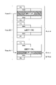
- FIG. 10 is a schematic diagram showing an example of fake image generation by an existing technique
- FIG. 10 is a schematic diagram showing an example of fake image generation by an existing technique
- FIG. 2 is a schematic diagram schematically showing a configuration example of a camera using a sensor that adds signature data to image data and outputs the image data according to an existing technique
- FIG. 3 is a schematic diagram showing an example of RAW data and signature data output from a sensor according to existing technology
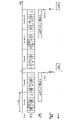
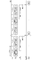
- FIG. 10 is a diagram for explaining a method of outputting signature data generated based on a moving image according to existing technology
- FIG. 10 is a diagram for explaining a method of outputting signature data generated based on a moving image according to existing technology
- 1 is a block diagram showing an example configuration of a camera applicable to each embodiment
- FIG. 3 is a block diagram showing an example configuration of a pixel array unit applicable to each embodiment;
- FIG. It is a figure which shows the example which formed the pixel array part which concerns on each embodiment by the lamination type CIS of a two-layer structure. It is a figure which shows the example which formed the pixel array part which concerns on each embodiment by the lamination-type CIS of a 3-layer structure.
- FIG. 4 is a diagram schematically showing a first example of an output format of moving image data applicable to each embodiment;
- FIG. 7 is a diagram schematically showing a second example of an output format of moving image data applicable to each embodiment;
- FIG. 7 is a diagram schematically showing a second example of an output format of moving image data applicable to each embodiment; It is a block diagram showing roughly the composition of the camera concerning each embodiment. BRIEF DESCRIPTION OF THE DRAWINGS It is a schematic diagram for demonstrating the outline
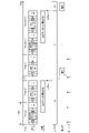
- FIG. 7 is a diagram for explaining a method of outputting signature data generated based on a moving image according to the embodiment;
- FIG. 5 is a schematic diagram for explaining the timing at which a signature processing unit executes signature data generation and encryption processing, which is applicable to each embodiment.
- 1 is a block diagram showing an example configuration of a sensor according to a first embodiment;
- FIG. FIG. 4 is a diagram for explaining a method of outputting signature data in the sensor according to the first embodiment;
- FIG. 4 is a diagram showing a first example of output positions of signature data applicable to the first embodiment
- FIG. 10 is a diagram showing a second example of output positions of signature data applicable to the first embodiment
- FIG. 10 is a diagram illustrating a third example of output positions of signature data applicable to the first embodiment
- FIG. 11 is a diagram for explaining an outline of a second embodiment
- FIG. 10 is a block diagram showing an example configuration of a sensor according to the first specific example of the second embodiment
- FIG. 11 is a diagram showing an example of a signature data calculation completion notification method according to the first specific example of the second embodiment
- FIG. 11 is a block diagram showing an example configuration of a sensor according to a second specific example of the second embodiment
- FIG. 12 is a diagram showing an example of a signature data calculation completion notification method according to a second specific example of the second embodiment
- FIG. 10 is a diagram showing an example of generation and output of signature data according to the third embodiment
- FIG. 12 is a diagram showing a usage example using a camera to which the above-described first, second and third embodiments are applicable, according to a fourth embodiment
- 1 is a block diagram showing a schematic configuration example of a vehicle control system, which is an example of a mobile body control system to which technology according to the present disclosure may be applied
- FIG. FIG. 4 is a diagram showing an example of an installation position of an imaging unit
- Figures 1 and 2 are schematic diagrams showing examples of fake image generation using existing technology.
- an image 301 that hides the lower half of an original image 300 is created, and based on this image 301, the lower half is predicted to generate an image 302a (fake image a) or a different image from the image 302a.
- a technique for generating an image 302b (fake image b) is known.
- a method is known in which a signature is added to the captured image, which is the original image, inside the sensor that acquires the captured image.
- FIG. 3A is a schematic diagram schematically showing a configuration example of a camera using a sensor that adds signature data to image data and outputs it, according to existing technology.
- camera 2000 includes sensor 2100 and image processor 2120 .
- the sensor 2100 includes a pixel array section 2110 and a signature processing section 2111, and is composed of, for example, one semiconductor chip (or a plurality of bonded semiconductor chips).
- the pixel array section 2110 includes a plurality of pixels that generate pixel signals according to the received light, and obtains image data in units of frames.
- the image data acquired here is unprocessed data in which pixel data based on pixel signals is not subjected to demosaic processing or the like.
- RAW data acquired by the pixel array unit 2110 is output from the interface 2101 according to the frame period.
- a signature processing unit 2111 generates signature data based on the RAW data acquired by the pixel array unit 2110 .
- the signature data generated by the signature processing unit 2111 is encrypted by a predetermined encryption method, and output from the interface 2101 in association with the corresponding RAW data.
- the signature data generated in the sensor 2100 is added to the RAW data output from the interface 2101, it is possible to prove that the RAW data is genuine (not falsified). For example, based on the RAW data output from the sensor 2100, signature data is generated in the same manner as the signature processing unit 2111, and when the generated signature data matches the signature data output from the sensor 2100, the RAW data It can prove that the data is genuine (not tampered with) RAW data.
- the RAW data and signature data output from the sensor 2100 are supplied to the image processing unit 2120.
- the image processing unit 2120 compresses and encodes the supplied RAW data using a moving picture compression method such as the MPEG (Moving Picture Experts Group) method. Compression-encoded MPEG data, for example, is output to the outside of the camera 2000 .
- MPEG Motion Picture Experts Group
- FIG. 3B is a schematic diagram showing an example of RAW data and signature data output from the sensor 2100 according to existing technology. As shown in FIG. 3B, RAW data 2201 and encrypted signature data 2202 are output for each frame according to the frame period.
- Common key cryptography and public key cryptography are examples of typical encryption schemes that can be applied to encrypt the signature data 2202 .
- DES Data Encryption Standard
- common key cryptosystem for example, operations equivalent to transposition and substitution that change according to the bit string of the encryption key, and exclusive logic for the data to be encrypted (plaintext) Encrypt the plaintext by repeating the operation with the sum (XOR).
- XOR exclusive logic for the data to be encrypted
- the computational load is relatively small, but since a common key is used for encryption and decryption, the side checking the image has the same key as the sensor side. It is inappropriate as an encryption method.
- the public key cryptosystem is suitable as an encryption system for falsification because different keys are used on the sensor side and the confirmation side.
- the plaintext P is encrypted into the ciphertext C by the following equation (1).
- Equation (1) is based on RSA (Rivest-Shamir-Adleman) encryption, which is one of public key cryptosystems.
- the value N is the product of two large prime numbers that are different from each other, and "mod N" represents the remainder modulo the value N.
- the value E is an arbitrarily chosen positive integer. A set of value E and value N is used as a public key.
- C P E mod N (1)
- the plaintext P is multiplied by a large value E to the power of E, and the remainder by the value N is calculated to obtain the ciphertext C. Therefore, compared with the encryption processing by the above-mentioned common key cryptosystem, the calculation load in encryption is very large, and encryption takes a long time.
- FIGS. 4A and 4B are diagrams for explaining a method of outputting signature data generated based on a moving image according to existing technology.
- [FS] and [FE] are lines including flags indicating frame start and frame end, respectively.
- [EBD] is a line containing a flag indicating embedded data. Multiple sets of [FS] and [FE] can be output in one frame period.
- [BLK] indicates a line with blank data.
- a signal Fsync indicates a frame synchronization signal and indicates passage of time in the right direction.
- FIG. 4A schematically shows an example of outputting signature data Sig for each frame of a moving image.
- the signature processing unit 2111 After reading one frame of image data (RAW data) from the pixel array unit 2110, the signature processing unit 2111 starts an operation for generating signature data based on the read image data.
- the signature data Sig is output for each frame by outputting the signature data Sig within the same frame period as the original image data.
- the signature data generation calculation by the signature processing unit 2111 includes the encryption calculation based on the above equation (1). , tens [msec (milliseconds)]. When the frame rate is 60 [fps (frames per second)], one frame period is approximately 16.7 [msec]. Therefore, when the signature data generation operation is started after the image data is read from the pixel array unit 2110, it is extremely difficult to output the signature data Sig within the same frame period as the image data. If it is necessary to output the signature data Sig in the same frame period as the reading of the image data, for example, it is necessary to reduce the frame rate or parallelize the processor.
- FIG. 4B schematically shows an example in which a frame for reading image data and a frame for outputting signature data Sig based on the image data are different.
- the signature processing unit 2111 starts signature data generation processing after image data is read out from the pixel array unit 2110, and generates signature data after the image data period of the next frame after the image data is read out. It outputs the signature data Sig.
- the signature data Sig can be output without failure.
- this method may complicate the management of the signature data Sig that is output with a delay for each frame.
- the frame rate is increased to 120 [fps] and 240 [fps]
- the frame rate is increased, the length of one frame period may become less than the time required for the signature processing unit 2111 to generate signature data. may become bulky.
- signature data is output every few frames of image data. As a result, it is possible to secure a sufficient amount of time from when the image data is output from the pixel array section in the sensor until when the signature data is output. In addition, it is possible to cope with the increase in frame rate by adjusting the interval of outputting the signature data.
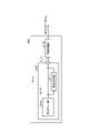
- FIG. 5 is a block diagram showing an example configuration of a camera applicable to each embodiment.
- camera 10 includes host device 20 and sensor 100 .
- the host device 20 includes an image processing section 120 .
- the sensor 100 includes a pixel array section 101 , a sensor control section 110 and a signature processing section 1000 .
- the sensor control unit 110 includes, for example, a processor and memory, and controls the operation of the entire sensor 100 according to a program stored in the memory.
- the pixel array unit 101 includes a plurality of pixels arranged in a matrix and each of which generates a pixel signal corresponding to the light received by exposure, and acquires image data based on each of the pixel signals generated by the plurality of pixels. .
- the pixel array unit 101 can acquire image data in frame cycles.
- the image data acquired by the pixel array unit 101 is unprocessed RAW data.
- the signature processing unit 1000 generates signature data based on the RAW data acquired by the pixel array unit 101 under the control of the sensor control unit 110, for example.
- RAW data acquired by the pixel array unit 101 in frame cycles is supplied to the image processing unit 120 included in the host device 20 .
- the image processing unit 120 performs predetermined image processing on the supplied RAW data to generate visible moving image data.
- the image processing unit 120 compresses and encodes the generated visible moving image data using a moving image compression encoding method such as the MPEG (Moving Picture Experts Group) method.
- the image processing unit 120 outputs the compressed moving image data obtained by compressing and encoding the moving image data to the outside of the camera 10 via a predetermined interface as output moving image data.
- the output video data output from the camera 10 is supplied to, for example, the display device 30 and displayed.
- the host device 20 includes the image processing unit 120 described above, and has, for example, a CPU (Central Processing Unit), a memory, and a predetermined interface, and gives instructions to the sensor 100 .
- the host device 20 is connected to the sensor 100 via a predetermined communication interface such as I 2 C (Inter-Integrated Circuit) or SPI (Serial Peripheral Interface).
- the host device 20 can give instructions to the camera 10 via this communication interface.
- the host device 20 can further have a communication interface capable of communicating with the outside of the camera 10 .
- the camera 10 according to each embodiment can be applied to surveillance purposes such as surveillance cameras and drive recorders. Not limited to this, the camera 10 according to each embodiment can also be applied to a camera mounted on a smart phone or a general video camera. Note that the uses of the camera 10 according to each embodiment are not limited to these.
- FIG. 6 is a block diagram showing an example configuration of the pixel array unit 101 applicable to each embodiment.
- the pixel array section includes a pixel array 102 , a vertical scanning section 400 , a horizontal scanning/AD conversion section 402 and a control section 401 .
- the pixel array 102 includes a plurality of pixels 103 each having an imaging element that generates a voltage according to the received light.
- a photodiode can be used as the imaging device.
- a plurality of pixels 103 are arranged in rows and columns in the horizontal direction (row direction) and vertical direction (column direction).
- the arrangement of the pixels 103 in the row direction is called a line.
- One frame of image (image data) is formed based on pixel signals read from a predetermined number of lines in the pixel array 102 . For example, when an image of one frame is formed by 3000 pixels ⁇ 2000 lines, the pixel array 102 includes at least 2000 lines each including at least 3000 pixels 103 .
- an area including pixels 103 used to form an image of one frame is called an effective pixel area.
- Image data formed in the pixel array 102 is RAW data.
- a pixel signal line HCTL is connected to each row and column of each pixel 103, and a vertical signal line VSL is connected to each column.
- the ends of the pixel signal lines HCTL that are not connected to the pixel array 102 are connected to the vertical scanning unit 400 .
- the vertical scanning unit 400 transmits a plurality of control signals such as drive pulses for reading out pixel signals from the pixels 103 to the pixel array 102 via the pixel signal lines HCTL according to control signals supplied from the control unit 401, for example.
- the ends of the vertical signal lines VSL that are not connected to the pixel array 102 are connected to the horizontal scanning/AD conversion unit 402 .
- the horizontal scanning/AD conversion unit 402 includes an AD (Analog to Digital) conversion unit, an output unit, and a signal processing unit.
- a pixel signal read from the pixel 103 is transmitted to the AD conversion unit of the horizontal scanning/AD conversion unit 402 via the vertical signal line VSL.
- a pixel signal is read out from the pixel 103 by transferring the charge accumulated in the image sensor due to exposure to a floating diffusion layer (FD) and converting the transferred charge into a voltage in the floating diffusion layer.
- FD floating diffusion layer
- a voltage resulting from charge conversion in the floating diffusion layer is output to the vertical signal line VSL via an amplifier.
- the floating diffusion layer and the vertical signal line VSL are connected according to the selection signal supplied through the pixel signal line HCTL. Furthermore, the floating diffusion layer is connected to the power supply voltage VDD or the black level voltage supply line for a short period of time in response to a reset pulse supplied through the pixel signal line HCTL to reset the floating diffusion layer.
- a reset level voltage (referred to as voltage P) of the floating diffusion layer is output to the vertical signal line VSL.
- a transfer pulse supplied through the pixel signal line HCTL turns on (closes) the state between the imaging element and the floating diffusion layer, thereby transferring the charges accumulated in the imaging element to the floating diffusion layer.
- a voltage (referred to as voltage Q) corresponding to the amount of charge in the floating diffusion layer is output to the vertical signal line VSL.
- the AD conversion unit includes an AD converter provided for each vertical signal line VSL, and pixel signals supplied from the pixels 103 via the vertical signal line VSL are converted by the AD converter.
- AD conversion processing is performed to generate two digital values (values corresponding to voltage P and voltage Q, respectively) for correlated double sampling (CDS) processing for noise reduction.
- CDS correlated double sampling
- the two digital values generated by the AD converter are subjected to CDS processing by the signal processing unit to generate pixel signals (pixel data) as digital signals.
- the generated pixel data is output from the pixel array section.
- the horizontal scanning/AD conversion unit 402 Under the control of the control unit 401, the horizontal scanning/AD conversion unit 402 performs selective scanning for selecting the AD converter for each vertical signal line VSL in a predetermined order. It sequentially outputs each digital value stored in the signal processing unit.
- the horizontal scanning/AD conversion unit 402 realizes this operation by a configuration including, for example, a shift register and an address decoder.
- the control unit 401 controls the driving of the vertical scanning unit 400, the horizontal scanning/AD conversion unit 402, etc. according to the control signal supplied from the sensor control unit 110, for example.
- the control unit 401 generates various drive signals that serve as references for the operations of the vertical scanning unit 400 and the horizontal scanning/AD conversion unit 402 .
- the vertical scanning unit 400 supplies the signal to each pixel 103 via the pixel signal line HCTL.
- Generate a control signal for The control section 401 supplies the generated control signal to the vertical scanning section 400 .
- the control unit 401 may be part of the functions of the sensor control unit 110 .
- the vertical scanning unit 400 Based on the control signal supplied from the control unit 401, the vertical scanning unit 400 supplies various signals including drive pulses to the pixel signal line HCTL of the pixel row selected in the pixel array 102 to each pixel 103 line by line. , to output a pixel signal from each pixel 103 to the vertical signal line VSL.
- the vertical scanning unit 400 is configured using, for example, shift registers and address decoders.
- the pixel array section configured in this manner is a column AD type CMOS (Complementary Metal Oxide Semiconductor) image sensor in which an AD converter is arranged for each column.
- CMOS Complementary Metal Oxide Semiconductor
- the pixel array section 101 can apply a CMOS image sensor (CIS) in which each section included in the pixel array section 101 is integrally formed using CMOS (Complementary Metal Oxide Semiconductor).
- CMOS Complementary Metal Oxide Semiconductor
- the pixel array section 101 can be formed on one substrate.
- the pixel array section 101 is not limited to this, and may be a laminated CIS in which a plurality of semiconductor chips are laminated and integrally formed.
- the pixel array unit 101 is not limited to this example, and may be another type of optical sensor such as an infrared light sensor that performs imaging using infrared light.
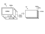
- the pixel array section 101 can be formed by a stacked CIS having a two-layer structure in which semiconductor chips are stacked in two layers.
- FIG. 7A is a diagram showing an example in which the pixel array section 101 according to each embodiment is formed by a laminated CIS having a two-layer structure.
- the pixel section 3020a is formed in the semiconductor chip of the first layer
- the memory+logic section 3020b is formed in the semiconductor chip of the second layer.
- the pixel section 3020 a includes at least the pixel array 102 in the pixel array section 101 .
- the memory+logic unit 3020b can include, for example, a vertical scanning unit 400, a control unit 401, a horizontal scanning/AD conversion unit 402, and a signature processing unit 1000.
- the memory+logic unit 3020b may further include a memory for storing image data such as RAW data.
- the pixel array section 101 is configured as one solid-state imaging device by bonding the semiconductor chips of the first layer and the semiconductor chips of the second layer in electrical contact with each other. .
- the pixel array section 101 can be formed with a three-layer structure in which semiconductor chips are stacked in three layers.
- FIG. 7B is a diagram showing an example in which the pixel array section 101 according to each embodiment is formed by a laminated CIS having a three-layer structure.
- the pixel section 3020a is formed in the semiconductor chip of the first layer
- the memory section 3020c is formed in the semiconductor chip of the second layer
- the logic section 3020d is formed in the semiconductor chip of the third layer.
- the logic unit 3020d can include a vertical scanning unit 400, a control unit 401, a horizontal scanning/AD conversion unit 402, and a signature processing unit 1000, for example.
- the memory unit 3020c can include a memory for storing image data such as RAW data.
- the first layer semiconductor chip, the second layer semiconductor chip, and the third layer semiconductor chip are bonded while being in electrical contact with each other, thereby forming the pixel array section 101. It is configured as one solid-state imaging device.
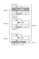
- FIG. 8 is a diagram schematically showing a first example of a moving image data output format applicable to each embodiment.
- section (a) shows the data arrangement for one frame of moving image data according to the format of the first example.
- the horizontal direction corresponds to the row direction (line)
- the vertical direction corresponds to the column direction
- XVS indicates a vertical synchronizing signal
- XHS indicates a horizontal synchronizing signal.
- the left side of the drawing indicates the head side of the line. That is, the moving image data is output line by line from left to right in the drawing, and each line is output from top to bottom in the drawing.
- a field [Start Code] and a field [Packet Header] are arranged from the beginning.
- a field [Start Code] indicates the beginning of each line.
- the field [Packet Header] will be described later.
- a data field is placed following the field [Packet Header].
- the data fields are arranged in the order of field [Blanking Data], field [Embedded Data], field [Pixel Data], and field [Blanking Data] from the top of the frame.
- the field [Pixel Data] is a field in which each pixel data in a moving image of one frame is output line by line. Also, the two fields [Blanking Data] correspond to the vertical blanking period of moving image data.
- the field [Embedded Data] is a field in which arbitrary data can be embedded.
- the field [End Code], the field [Deskew Code], and the field [Idle Code] are arranged.
- the field [End Code] indicates the end of each line.
- the field [Deskew Code] is a field for packet synchronization.
- the field [Idle Code] corresponds to the horizontal ranking period of each line.
- Section (b) of FIG. 8 shows in more detail the contents of the field [Packet Header] shown in section (a).
- the field [Packet Header] is assigned a data size of 48 bits from the 0th bit to the 47th bit, and stores information indicating the line corresponding to the field [Packet Header].
- the 47th bit stores a flag [FS] indicating the frame start.
- the 46th bit stores a flag [FE] indicating the frame end.
- the 45th bit stores a flag [Valid] indicating that the line is valid.
- the line number [Line Number] of the line is stored in the 44th to 32nd bits.
- a flag [EBD] indicating embedded data is stored in the 31st bit.
- Identification information [ID] indicating the type of the line is stored in the 30th to 27th bits. Bits 26 to 0 are reserved areas (RESERVE).
- identification information [ID] can be used to indicate that the line is related to signature data Sig.
- MIPI Mobile Industry Processor Interface
- 9A and 9B are diagrams schematically showing a second example of the output format of moving image data applicable to each embodiment.
- MIPI registered trademark
- MIPI defines a long packet and a short packet as data formats for output data. It should be noted that in FIGS. 9A and 9B, the left side is the leading side of the data.
- FIG. 9A shows a data format by long packets in MIPI (registered trademark).
- the upper part of FIG. 9A shows the packet structure.
- a long packet starts with a 4-byte packet header [PH], followed by n-byte payload data (Payload Data), and ends with a 4-byte packet footer [PF].
- Payload data is the main part of the data transferred by this packet, and image data and signature data can be applied.
- FIG. 9A shows the contents of the packet header [PH].
- a 1-byte data identifier [DI] In the packet header [PH], a 1-byte data identifier [DI], a 2-byte word count [WC], and a 1-byte error correction code [ECC] are arranged in order from the top.
- the lower part of FIG. 9A shows the contents of the data identifier [DI].
- a virtual channel [VC] and a data type [DT] are arranged in order from the top.
- FIG. 9B shows a data format by short packets in MIPI (registered trademark).
- the upper part of FIG. 9B shows the packet structure. Thus, in short packets, only the packet header [PH] is defined.
- the lower part of FIG. 9B shows the contents of the packet header [PH].
- a 1-byte data identifier [DI] a 2-byte frame number or line number [FN/LN]
- ECC error correction code
- the data identifier [DI] can be used to indicate that the line is related to the signature data Sig.
- FIG. 10A schematically shows the configuration of the camera 10 according to each embodiment.
- the camera 10 includes a host device 20 and a sensor 100, similar to the camera 10 shown in FIG.
- the host device 20 includes an image processing section 120 .
- the sensor 100 also includes a pixel array section 101 and a signature processing section 1000 .
- the sensor control unit 110 includes, for example, a processor and memory, and controls the operation of the sensor 100 according to programs stored in the memory.
- the host device 20 also includes a CPU and memory, and controls the overall operation of the camera 10, such as giving instructions to the sensor 100, according to programs stored in the memory.
- the sensor 100 generates the signature data 210 by the signature processing unit 1000 based on the image data (RAW data 200) acquired by the pixel array unit 101 in frame cycles.
- the RAW data 200 acquired by the unit 101 is output from the interface 130 .
- the signature data 210 and the RAW data 200 output from the interface 130 are supplied to the image processing section 120 .
- the image processing unit 120 performs compression encoding processing on the supplied RAW data 200 and outputs output moving image data 230 based on the compression encoded RAW data 200 . Further, the image processing unit 120 outputs the signature data 210 generated based on the RAW data 200 before compression encoding in the output moving image data 230 as authentication data for the RAW data 200 .
- FIG. 10B is a schematic diagram for explaining data output from the interface 130 of the sensor 100.
- FIG. 10B the passage of time is shown in the right direction.
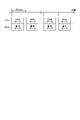
- the signature processing unit 1000 generates signature data 210 for every n frames (n is an integer equal to or greater than 2) for the RAW data 200 output by the pixel array unit 101 at frame intervals.
- the signature processing unit 1000 thins out the RAW data 200 output by the pixel array unit 101 in frame cycles, using (n ⁇ 1) frames as a thinning unit, and thins out the RAW data 200 in units of thinning to obtain signature data.
- 210 is generated.
- the signature processing unit 1000 generates the signature data 210 based on the RAW data 200 of the first frame Frame#1, for example. does not generate signature data 210 . That is, signature processing section 1000 generates signature data 210 by thinning out (n ⁇ 1) frames of frames Frame#2 to Frame#n.
- the signature processing unit 1000 generates signature data 210 based on the RAW data 200 of the next frame Frame#(n+1), and from the next frame Frame#(n+2) to Frame#2n (not shown), Do not generate signature data 210 .
- FIG. 11 is a diagram for explaining a method of outputting signature data 210 generated based on a moving image according to the embodiment.
- signature processing section 1000 performs generation and encryption processing of signature data 210 based on image data #1 (RAW data) of first frame Frame #1. It should be completed within a period from the rear end of the output to the rear end of the n-th frame Frame#n at the longest. Therefore, the signature processing unit 1000 according to each embodiment can generate the signature data 210 in a sufficiently long time compared to the generation of the signature data by the existing technology described with reference to FIGS. 4A and 4B. can.
- RAW data image data #1
- the value n in FIG. 11, that is, the interval for generating the signature data 210 is not fixed, and can be set as appropriate to an interval at which the generation and encryption of the signature data 210 can be completed.
- setting the value n to the register of the sensor 100 from the host device 20 is conceivable.
- FIG. 12 is a schematic diagram for explaining the timing at which the signature processing unit 1000 generates and encrypts the signature data 210, which is applicable to each embodiment.
- the passage of time is shown in the right direction, and the frame synchronization signal (signal Fsync), for example, processor processing in the sensor control unit 110, and output data from the interface 130 are shown from the top.
- the frame synchronization signal signal Fsync
- processing #1 indicates processing for the next frame, such as setting the operation mode.
- Processing #2 indicates processing after acquisition of image data, such as exposure and white balance adjustment. These process #1 and process #2 are executed for each frame.
- Processing #3 and processing #4 are processing other than processing #1 and processing #2, such as MAC (Memory Access Control) processing in register communication of sensor 100 and temperature calculation processing within sensor 100. Process #3 and process #4 are interrupt processes that are not executed for each frame.
- MAC Memory Access Control
- the sensor control unit 110 controls the signature processing unit 1000 to generate and encrypt the signature data 210 during periods P#1, P#2, . . . between these processes #1 to #4. do.
- the senor outputs image data (RAW data 200) output from the pixel array unit 101 and encrypted signature data 210 generated based on the image data from one interface. For example.
- FIG. 13 is a block diagram showing an example configuration of a sensor according to the first embodiment.
- the sensor 100a includes a pixel array section 101, a signature processing section 1000a, an output interface (I/F) 104, and a communication/sensor control section 105a.
- the communication/sensor control unit 105 communicates with the host device 20 via the interface 131 .
- I 2 C Inter-Integrated Circuit
- SPI Serial Peripheral Interface
- I 3 C Inter Integrated Circuits
- I 2 C Inter-Integrated Circuits
- I 3 C Inter Integrated Circuits
- the communication/sensor control unit 105 corresponds to the sensor control unit 110 in FIG. 10A, and includes, for example, a processor and a memory. control behavior.
- the pixel array section 101 is shown to include a pixel array 102, a pixel control section 107, and an ADC (Analog to Digital Converter) .
- the pixel control unit 107 corresponds to, for example, the vertical scanning unit 400 and the output unit in the horizontal scanning/AD conversion unit 402 shown in FIG.
- the ADC 108 corresponds to the AD converter in the horizontal scanning/AD converter 402 shown in FIG.
- the signature processing unit 1000a includes a data processing unit 1010 and a signature generation unit 1021.
- RAW data 200 output from the pixel array unit 101 is input to the data processing unit 1010 .
- the data processing unit 1010 performs predetermined data processing on the input RAW data 200 so that the image processing unit 120 (not shown) in the subsequent stage performs image processing.
- the RAW data 200 processed by the data processing unit 1010 is supplied to the output I/F 104 and signature generation unit 1021 .
- the signature generation unit 1021 generates signature data 210 based on the RAW data 200 supplied from the data processing unit 1010 .
- the signature generation unit 1021 generates a hash value from the supplied RAW data 200 and uses the generated hash value as the signature data 210 .
- the signature generation unit 1021 can use a value generated by another algorithm as the signature data 210 as long as the value can uniquely identify the RAW data 200 and is difficult to guess.
- the signature generation unit 1021 encrypts the generated signature data 210 using a pre-stored private key in public key cryptography, and supplies the encrypted signature data 210 to the output I/F 104. .
- the encrypted signature data 210 is simply referred to as "signature data 210".
- FIG. 14 is a diagram for explaining a method of outputting the signature data 210 in the sensor 100a according to the first embodiment.
- the signature data 210 is shown as signature data Sig.
- the output I/F 104 outputs the signature data Sig generated based on the image data #1, which is RAW data, output in the first frame Frame#1, for example, in the nth frame. It is output sandwiched between the second [FS] and [FE] in frame #n after image data #n of #n.
- the output I/F 104 functions as an output control unit that controls the output of the image data and the signature data Sig.
- FIG. 15 is a diagram showing a first example of output positions of signature data Sig applicable to the first embodiment.
- the first example shown in FIG. 15 corresponds to the output position of the signature data Sig in FIG. 14 described above. That is, the output I/F 104 converts the signature data Sig generated based on the image data #1 output in the first frame Frame#1 into a packet indicating the start and end of the frame Frame#n (SLVS-EC In this case, it is sandwiched between the second set [FS] and [FE]) and output.
- the output I/F 104 makes the value of the identification information [ID] in the packet header of each line different between the area containing the signature data Sig and the area not containing the signature data Sig.
- identification information [ID] [4'h1] in an area (line) containing signature data Sig
- identification information [ID] [4'h1] in an area (line) not containing signature data Sig. [4'h0].
- [4'h] indicates that the following number is a value represented by 4 bits.
- VC] [2′h0].
- [2'h] indicates that the following number is a value represented by 2 bits.
- the value of the data type [DT] may indicate an area (line) containing the signature data Sig and an area (line) not containing the signature data Sig. For example, it is possible to switch between the virtual channel [VC] and the data type [DT] according to the configuration of the receiving side (for example, the host device 20) of the output from the sensor 100a.
- FIG. 16 is a diagram showing a second example of the output position of signature data Sig applicable to the first embodiment.
- an embedding area for storing the signature data Sig is provided in the frame.
- the line can be made an embedding area in which predetermined data can be embedded.
- the output I/F 104 puts the signature data Sig generated based on the image data #1 output in the first frame Frame#1 after the image data #n of the frame Frame#n. It is embedded in an embedding area provided for data Sig.
- the signature data Sig obtained in the previous frame may be re-output. Also, if the frame for which the signature data Sig is not output is known, it is conceivable that nothing is done.
- lines containing signature data Sig and lines not containing signature data Sig can be indicated by the value of virtual channel [VC] or data type [DT], as described above.
- FIG. 17 is a diagram showing a third example of the output position of signature data Sig applicable to the first embodiment.
- signature data Sig is output as line data by lines with different header information from lines of normal image data.
- the value of the line number [Line Number] in the packet header [Packet Header] is different between lines containing signature data Sig and lines not containing signature data Sig.
- the value of the virtual channel [VC] or the data type [DT] is made different between lines containing signature data Sig and lines not containing signature data Sig.
- the timing of outputting the signature data Sig is the last frame of the thinning unit.
- the signature data Sig generated based on the RAW data 200 output in the first frame is the n-th Output in frames.
- the output timing of the signature data Sig is not limited to this example.
- the output I/F 104 may output the signature data Sig in the frame following the last frame of the thinning unit. In this case, as indicated by the dotted arrow in FIG. 14, for example, output may be performed at the timing of [BLK] at the rear end of the next frame.
- the output I/F 104 may output the signature data Sig in a frame corresponding to the timing when the computation of the signature data Sig is completed. In this case, the output I/F 104 outputs the signature data Sig from the frame next to the frame of the RAW data 200 corresponding to the signature data Sig to the end of (n ⁇ 1) frames in the thinning unit. will do.
- the output I/F 104 may output the signature data Sig in a frame specified in advance based on the frame of the RAW data 200 corresponding to the signature data Sig.
- the second embodiment is an example in which the sensor outputs image data (RAW data 200) output from the pixel array unit 101 and encrypted signature data 210 generated based on the image data from different interfaces. is.
- RAW data 200 image data
- encrypted signature data 210 generated based on the image data from different interfaces.
- FIG. 18 is a diagram for explaining the outline of the second embodiment.
- the configuration of the sensor 100a in FIG. 13 will be referred to.
- the passage of time is shown to the right, and from the top, the frame synchronization signal (signal Fsync), the output data from the interface 133, the internal state of the signature processing unit 1000a (internal state), and the signature data by the signature processing unit 1000a.
- the completion notification of the generation calculation and the output by the communication I/F (interface 131) are shown respectively.
- the signature generation unit 1021 starts the calculation of signature data Sig generation (signature data Sig generation and encryption) based on the image data #1. be done.
- signature data Sig generation signature data Sig generation and encryption
- the signature generation unit 1021 notifies the communication/sensor control unit 105a of the completion of the operation at time t11 immediately after time t10 .
- the signature data Sig is acquired by the host device 20 via the interface 131 at time t 12 after a predetermined time from time t 11 .
- the process of embedding the signature data Sig into the output video data 230 output from the interface 130 becomes unnecessary, and the load on the output I/F 104 can be reduced. It becomes possible.
- the signature generating unit 1021 can add information indicating the RAW data 200 corresponding to the generated signature data Sig to the generated signature data Sig.
- the communication/sensor control unit 105a may add information indicating the RAW data 200 to the signature data Sig.
- the generated signature data Sig is stored in a storage unit such as a register of the communication/sensor control unit 105a, and stored in the storage unit from the host device 20 via the interface 131.
- signature data Sig is stored in a storage unit such as a register of the communication/sensor control unit 105a, and stored in the storage unit from the host device 20 via the interface 131.
- the second embodiment proposes the following first and second specific examples.
- FIG. 19 is a block diagram showing an example configuration of a sensor according to the first specific example of the second embodiment.
- the senor 100b is provided with an interrupt signal port 132 for transmitting an interrupt signal to the outside (for example, the host device 20).
- signature processing section 1000 b signature generation section 1021 outputs an interrupt signal to this interrupt signal port 132 .
- Interrupt signal port 132 and interface 131 are connected to host device 20 (not shown).
- FIG. 20 is a diagram showing an example of a signature data computation completion notification method according to the first specific example of the second embodiment.
- the passage of time is shown to the right, and from the top, the frame synchronization signal (signal Fsync), the output data from the interface 133, the internal state of the signature processing unit 1000b (internal state), and the output from the interrupt signal port 132. interrupt signal and output from the communication I/F (interface 131).
- the signature generation unit 1021 stores the generated signature data Sig in the register 1051 as a storage unit of the communication/sensor control unit 105b. Further, upon completion of generation of signature data Sig at time t10, signature generation section 1021 outputs an interrupt signal indicating completion of computation from interrupt signal port 132 at time t11 immediately after time t10.
- the host device 20 connected to the interrupt signal port 132 communicates with the communication/sensor control unit 105b via the interface 131, and at time t12 after a predetermined time from time t11 , Acquisition of signature data Sig from register 1051 is started.
- the host device 20 previously knows the register address where the signature data Sig is stored in the register 1051, and reads out the signature data Sig from the register 1051 based on this register address.
- the output I/F 104, the signature generation unit 1021, and the communication/sensor control unit 105b control the output of the image data and the signature data Sig.
- An output control section is configured.
- the interrupt signal is output as a pulse signal from the interrupt signal port 132 in the example of FIG. 20, this is not limited to this example.
- the signature generation unit 1021 may output interrupt completion in a state.
- the signature generation unit 1021 sets the interrupt signal port 132 to a high state at the completion of the operation (time t 10 ), and at the timing (time t 11 ) at which the signature data Sig can be read from the register 1051, It is conceivable to set the interrupt signal port 132 to a low state.
- FIG. 21 is a block diagram showing an example configuration of a sensor according to a second specific example of the second embodiment.
- the signature processing unit 1000c is provided with a signature generation/update management unit 1022 instead of the signature generation unit 1021.
- the signature generation/update management unit 1022 generates and encrypts the signature data Sig based on the RAW data supplied from the data processing unit 1010, similarly to the signature generation unit 1021 described above, and transmits the generated signature data Sig. ⁇ Store in the register 1051 of the sensor control unit 105c.
- the signature generation/update management unit 1022 transmits state data 1061 indicating that the signature data Sig has been newly stored in the register 1051 to the communication/sensor control unit 105c.
- the communication/sensor control unit 105 c updates the information indicating the state of the register 1051 according to the state data 1061 .
- Information indicating the state of this register 1051 is polled from the host device 20 (not shown) via the interface 131 .
- the host device 20 accesses the register 1051 via the interface 131 and acquires the signature data Sig stored in the register 1051 when a change in the state of the register 1051 is detected based on the polling result.
- FIG. 22 is a diagram showing an example of a signature data calculation completion notification method according to the second specific example of the second embodiment.
- the passage of time is shown to the right, and from the top, the frame synchronization signal (signal Fsync), the output data from the interface 133, the internal state of the signature processing unit 1000c (internal state), and information indicating the state of the register 1051. (count value), output from the communication I/F (interface 131), and polling from the host device 20, respectively.
- signature generation/update management unit 1022 stores generated signature data Sig in register 1051 as a storage unit of communication/sensor control unit 105c. to the communication/sensor control unit 105c.
- the communication/sensor control unit 105 c updates the information indicating the state of the register 1051 according to the state data 1061 .
- the communication/sensor control unit 105c has a counter. is incremented by 1.
- the count value indicating the state of the register is incremented from [0] to [ 1 ] before and after time t11. This count value is written to the register 1051, for example.
- the host device 20 connected to the interface 131 polls the register 1051 through the interface 131 at predetermined intervals to obtain a count value indicating the state of the register. If the acquired count value is different from the previously acquired count value, the host device 20 assumes that new signature data Sig is stored in the register 1051, and at time t 20 , the signature data Sig from the register 1051 is Start reading.
- the output I/F 104, the signature generation/update management unit 1022, and the communication/sensor control unit 105c output image data and signature data Sig.
- An output control unit for controlling is configured.
- the communication/sensor control unit 105c uses the count value incremented according to the state data 1061 as information indicating the state of the register 1051, but this is not limited to this example.
- the communication/sensor control unit 105 c may indicate the state of the register 1051 by switching between a high state and a low state according to the state data 1061 .
- the third embodiment of the present disclosure is an example of generating signature data Sig for an image data group including multiple image data.
- any of the sensor 100a according to the first embodiment and the sensors 100b and 100c according to the first and second specific examples of the second embodiment can be applied. In the following description, it is assumed that the sensor 100a according to the first embodiment is applied to the third embodiment.
- image data captured in distance measurement processing of iToF indirect ToF (Time of Flight)
- iToF Indirect ToF (Time of Flight)
- the object to be measured is irradiated with light source light (for example, infrared laser light) modulated by PWM (Pulse Width Modulation)
- the reflected light is received by a light receiving element, and the received reflected light is
- PWM Pulse Width Modulation
- the reflected light is received by a light receiving element, and the received reflected light is
- This is a technique for measuring the distance to the object to be measured based on the phase difference between the two.
- the light amount values C 0 and C 90 , C 180 and C 270 respectively.
- the image data (iToF data 0°) obtained by exposure with a phase of 0° is obtained in Frame#1
- the image data (iToF data 180°) obtained by exposure with a phase of 180° is obtained in the next frame Frame#2.
- image data (iToF90°) is obtained by exposure of phase 90° in frame #3
- image data (iToF270°) is obtained by exposure of phase 270° in the next frame (Frame#4 (not shown)).
- FIG. 23 is a diagram showing an example of generation and output of signature data according to the third embodiment.
- the signature generation unit 1021 configures one image data group by collecting iToF data 0° and iToF data 180°, for example.
- the signature generation unit 1021 generates signature data Sig based on iToF data 0° and iToF data 180° included in this image data group.
- the signature generation unit 1021 integrates iToF data 0° and iToF data 180° to generate one signature data Sig.
- the generated signature data Sig is output, for example, at a predetermined position of Frame#n.
- the signature generation unit 1021 collects the iToF data 90° and the iToF data 270° to form one image data group, and iToF data included in this image data group.
- Signature data Sig is generated based on the data 90° and the iToF data 270°. Although illustration is omitted, the generated signature data Sig is output, for example, at a predetermined position of Frame#(n+2).
- the signature generation unit 1021 may generate signature data Sig for each of a plurality of image data included in one image data group. In this case, a plurality of generated signature data Sig can be output for the same frame.
- the method of generating and outputting signature data Sig according to the third embodiment is applied to image data acquired in the iToF range finding process, but this is not limited to this example. That is, the image data group may include other types of image data as long as the image data makes sense in a plurality of frames. Also, in the above description, two image data are grouped into one image data group, but this is not limited to this example, and three or more image data may be grouped into one image data group.
- FIG. 24 is a diagram showing a usage example using the camera 10 to which the above-described first, second, and third embodiments are applicable, according to the fourth embodiment.
- the camera 10 described above can be used in various cases for sensing light such as visible light, infrared light, ultraviolet light, and X-rays as follows.
- a device that takes pictures for viewing such as a digital camera or a mobile device with a camera function.
- a device used for transportation such as a ranging sensor that measures the distance of a vehicle.
- a device used in home appliances such as TVs, refrigerators, air conditioners, etc., to photograph a user's gesture and operate the device according to the gesture.
- Medical and health care devices such as endoscopes and devices that perform angiography by receiving infrared light.
- ⁇ Devices used for security such as monitoring cameras for crime prevention and cameras for person authentication.
- ⁇ Equipment used for beauty care such as a skin measuring instrument for photographing the skin and a microscope for photographing the scalp.
- ⁇ Equipment used for sports such as action cameras and wearable cameras for sports.
- Equipment for agricultural use such as cameras for monitoring the condition of fields and crops.
- FIG. 25 is a block diagram showing a schematic configuration example of a vehicle control system, which is an example of a mobile control system to which the technology according to the present disclosure can be applied.
- a vehicle control system 12000 includes a plurality of electronic control units connected via a communication network 12001.
- vehicle control system 12000 includes drive system control unit 12010 , body system control unit 12020 , vehicle exterior information detection unit 12030 , vehicle interior information detection unit 12040 , and integrated control unit 12050 .
- integrated control unit 12050 As the functional configuration of the integrated control unit 12050, a microcomputer 12051, an audio/image output section 12052, and an in-vehicle network I/F (interface) 12053 are illustrated.
- the drive system control unit 12010 controls the operation of devices related to the drive system of the vehicle according to various programs.
- the driving system control unit 12010 includes a driving force generator for generating driving force of the vehicle such as an internal combustion engine or a driving motor, a driving force transmission mechanism for transmitting the driving force to the wheels, and a steering angle of the vehicle. It functions as a control device such as a steering mechanism to adjust and a brake device to generate braking force of the vehicle.
- the body system control unit 12020 controls the operation of various devices equipped on the vehicle body according to various programs.
- the body system control unit 12020 functions as a keyless entry system, a smart key system, a power window device, or a control device for various lamps such as headlamps, back lamps, brake lamps, winkers or fog lamps.
- the body system control unit 12020 can receive radio waves transmitted from a portable device that substitutes for a key or signals from various switches.
- the body system control unit 12020 receives the input of these radio waves or signals and controls the door lock device, power window device, lamps, etc. of the vehicle.
- the vehicle exterior information detection unit 12030 detects information outside the vehicle in which the vehicle control system 12000 is installed.
- the vehicle exterior information detection unit 12030 is connected with an imaging section 12031 .
- the vehicle exterior information detection unit 12030 causes the imaging unit 12031 to capture an image of the exterior of the vehicle, and receives the captured image.
- the vehicle exterior information detection unit 12030 may perform object detection processing or distance detection processing such as people, vehicles, obstacles, signs, or characters on the road surface based on the received image.
- the vehicle exterior information detection unit 12030 for example, performs image processing on the received image, and performs object detection processing and distance detection processing based on the result of the image processing.
- the imaging unit 12031 is an optical sensor that receives light and outputs an electrical signal according to the amount of received light.
- the imaging unit 12031 can output the electric signal as an image, and can also output it as distance measurement information.
- the light received by the imaging unit 12031 may be visible light or non-visible light such as infrared rays.
- the in-vehicle information detection unit 12040 detects in-vehicle information.
- the in-vehicle information detection unit 12040 is connected to, for example, a driver state detection section 12041 that detects the state of the driver.
- the driver state detection unit 12041 includes, for example, a camera that captures an image of the driver, and the in-vehicle information detection unit 12040 detects the degree of fatigue or concentration of the driver based on the detection information input from the driver state detection unit 12041. It may be calculated, or it may be determined whether the driver is dozing off.
- the microcomputer 12051 calculates control target values for the driving force generator, the steering mechanism, or the braking device based on the information inside and outside the vehicle acquired by the vehicle exterior information detection unit 12030 or the vehicle interior information detection unit 12040, and controls the drive system control unit.
- a control command can be output to 12010 .
- the microcomputer 12051 realizes the functions of ADAS (Advanced Driver Assistance System) including collision avoidance or shock mitigation, follow-up driving based on inter-vehicle distance, vehicle speed maintenance driving, vehicle collision warning, vehicle lane departure warning, etc. Cooperative control can be performed for the purpose of ADAS (Advanced Driver Assistance System) including collision avoidance or shock mitigation, follow-up driving based on inter-vehicle distance, vehicle speed maintenance driving, vehicle collision warning, vehicle lane departure warning, etc. Cooperative control can be performed for the purpose of ADAS (Advanced Driver Assistance System) including collision avoidance or shock mitigation, follow-up driving based on inter-vehicle distance, vehicle speed maintenance driving, vehicle collision warning, vehicle
- the microcomputer 12051 controls the driving force generator, the steering mechanism, the braking device, etc. based on the information about the vehicle surroundings acquired by the vehicle exterior information detection unit 12030 or the vehicle interior information detection unit 12040, so that the driver's It is possible to perform cooperative control for the purpose of automatic driving, etc., in which the vehicle autonomously runs without depending on the operation.
- the microcomputer 12051 can output a control command to the body system control unit 12020 based on the information outside the vehicle acquired by the information detection unit 12030 outside the vehicle.
- the microcomputer 12051 controls the headlamps according to the position of the preceding vehicle or the oncoming vehicle detected by the vehicle exterior information detection unit 12030, and performs cooperative control aimed at anti-glare such as switching from high beam to low beam. It can be carried out.
- the audio/image output unit 12052 transmits at least one of audio and/or image output signals to an output device capable of visually or audibly notifying the passengers of the vehicle or the outside of the vehicle.
- an audio speaker 12061, a display section 12062 and an instrument panel 12063 are illustrated as output devices.
- the display unit 12062 may include at least one of an on-board display and a head-up display, for example.
- FIG. 26 is a diagram showing an example of the installation position of the imaging unit 12031.
- vehicle 12100 has imaging units 12101 , 12102 , 12103 , 12104 and 12105 as imaging unit 12031 .
- the imaging units 12101, 12102, 12103, 12104, and 12105 are provided at positions such as the front nose, side mirrors, rear bumper, back door, and windshield of the vehicle 12100, for example.
- An image pickup unit 12101 provided in the front nose and an image pickup unit 12105 provided above the windshield in the passenger compartment mainly acquire images in front of the vehicle 12100 .
- Imaging units 12102 and 12103 provided in the side mirrors mainly acquire side images of the vehicle 12100 .
- An imaging unit 12104 provided in the rear bumper or back door mainly acquires an image behind the vehicle 12100 .
- the forward images acquired by the imaging units 12101 and 12105 are mainly used for detecting preceding vehicles, pedestrians, obstacles, traffic lights, traffic signs, lanes, and the like.
- FIG. 25 shows an example of the imaging range of the imaging units 12101-12104.
- the imaging range 12111 indicates the imaging range of the imaging unit 12101 provided in the front nose
- the imaging ranges 12112 and 12113 indicate the imaging ranges of the imaging units 12102 and 12103 provided in the side mirrors, respectively
- the imaging range 12114 The imaging range of an imaging unit 12104 provided on the rear bumper or back door is shown. For example, by superimposing the image data captured by the imaging units 12101 to 12104, a bird's-eye view image of the vehicle 12100 viewed from above can be obtained.
- At least one of the imaging units 12101 to 12104 may have a function of acquiring distance information.
- at least one of the imaging units 12101 to 12104 may be a stereo camera composed of a plurality of imaging elements, or may be an imaging element having pixels for phase difference detection.
- the microcomputer 12051 determines the distance to each three-dimensional object within the imaging ranges 12111 to 12114 and changes in this distance over time (relative velocity with respect to the vehicle 12100). , it is possible to extract, as the preceding vehicle, the closest three-dimensional object on the course of the vehicle 12100, which runs at a predetermined speed (for example, 0 km/h or more) in substantially the same direction as the vehicle 12100. can. Furthermore, the microcomputer 12051 can set the inter-vehicle distance to be secured in advance in front of the preceding vehicle, and perform automatic brake control (including following stop control) and automatic acceleration control (including following start control). In this way, cooperative control can be performed for the purpose of automatic driving in which the vehicle runs autonomously without relying on the operation of the driver.
- automatic brake control including following stop control
- automatic acceleration control including following start control
- the microcomputer 12051 based on the distance information obtained from the imaging units 12101 to 12104, converts three-dimensional object data to other three-dimensional objects such as two-wheeled vehicles, ordinary vehicles, large vehicles, pedestrians, and utility poles. It can be classified and extracted and used for automatic avoidance of obstacles. For example, the microcomputer 12051 distinguishes obstacles around the vehicle 12100 into those that are visible to the driver of the vehicle 12100 and those that are difficult to see. Then, the microcomputer 12051 judges the collision risk indicating the degree of danger of collision with each obstacle, and when the collision risk is equal to or higher than the set value and there is a possibility of collision, an audio speaker 12061 and a display unit 12062 are displayed. By outputting an alarm to the driver via the drive system control unit 12010 and performing forced deceleration and avoidance steering via the drive system control unit 12010, driving assistance for collision avoidance can be performed.
- the microcomputer 12051 based on the distance information obtained from the imaging units 12101 to 12104, converts three-dimensional object data to other three-
- At least one of the imaging units 12101 to 12104 may be an infrared camera that detects infrared rays.
- the microcomputer 12051 can recognize a pedestrian by determining whether or not the pedestrian exists in the images captured by the imaging units 12101 to 12104 .
- recognition of a pedestrian is performed by, for example, a procedure for extracting feature points in images captured by the imaging units 12101 to 12104 as infrared cameras, and performing pattern matching processing on a series of feature points indicating the outline of an object to determine whether or not the pedestrian is a pedestrian.
- the audio image output unit 12052 outputs a rectangular outline for emphasis to the recognized pedestrian. is superimposed on the display unit 12062 . Also, the audio/image output unit 12052 may control the display unit 12062 to display an icon or the like indicating a pedestrian at a desired position.
- the technology according to the present disclosure can be applied to, for example, the imaging unit 12031 among the configurations described above.
- the camera 10 to which the first and second embodiments described above can be applied can be applied to the imaging unit 12031 .
- the technology according to the present disclosure to the imaging unit 12031, it becomes possible to output a moving image whose authenticity can be verified with a low load.
- an in-vehicle device it is possible to reduce power consumption and downsize the device.
- a plurality of pixels arranged in a matrix and each generating a pixel signal corresponding to light received by exposure are included, and image data based on each of the pixel signals generated by the plurality of pixels is output in a frame cycle.
- a pixel array section a signature generation unit that generates signature data based on the image data; an output control unit that controls output of the image data and the signature data; with The signature generation unit generating the signature data by thinning the image data output in the frame cycle in thinning units based on the frame cycle; Imaging device.
- the output control unit is outputting the signature data at timing after a predetermined time elapses with respect to output timing of the image data corresponding to the signature data; The imaging device according to (1) above.
- (3) The output control unit is outputting the image data and the signature data from the same output terminal; The imaging device according to (1) or (2) above.
- (4) The output control unit is outputting the signature data to the last frame obtained by thinning the image data that generated the signature data in the thinning unit; The imaging device according to (3) above.
- the output control unit is outputting the signature data to a frame next to the last frame obtained by thinning the image data that generated the signature data in the thinning unit; The imaging device according to (3) above.
- the output control unit is outputting the signature data to a frame corresponding to the timing at which the signature data was generated by the signature generation unit; The imaging device according to (3) above.
- the output control unit is outputting the signature data to a predesignated frame after a predetermined frame with respect to the image data that generated the signature data; The imaging device according to (3) above.
- the output control unit is outputting the signature data by adding information indicating the start of the frame and information indicating the end of the frame; The imaging apparatus according to any one of (3) to (7).
- the output control unit is storing the signature data in an embedded data area in a frame of the image data and outputting the signature data; The imaging apparatus according to any one of (3) to (7).
- the output control unit is adding lines in the row direction of the array to the image data, storing the signature data in the lines added to the image data, and outputting the signature data;
- the imaging apparatus according to any one of (3) to (7).
- the output control unit is a communication terminal for communicating with a host device, different from the output terminal for outputting the image data; a storage unit accessible from the host device via the communication terminal; including the signature data written in the storage unit by the signature generation unit is output from the communication terminal;
- the imaging device according to (1) or (2) above.
- the signature generation unit storing the generated signature data in the storage unit, outputting an interrupt signal indicating that the signature data has been generated from the interrupt signal port corresponding to the timing at which the signature data is generated, and outputting the interrupt outputting the signature data by reading the signature data stored in the storage unit by the host device in response to a signal;
- the imaging device according to (11) above.
- the signature generation unit storing the generated signature data in the storage unit, and changing state information indicating the state of the storage unit in the storage unit;
- the output control unit is The state information is confirmed by the host device through polling from the host device via the communication terminal, and the state information is stored in the storage unit by the host device when the state information has changed since the previous polling. outputting the signature data by reading the signature data;
- the imaging device according to (11) above.
- the signature generation unit generating the signature data for each image data group obtained by grouping the plurality of image data; The imaging apparatus according to any one of (1) to (13) above.
- (15) The signature generation unit generating one piece of signature data by integrating a plurality of the image data included in the image data group; The imaging device according to (14) above.
- the signature generation unit generating the signature data for each of the plurality of image data included in the image data group;
- the output control unit is encrypting the signature data using a private key in a public key cryptosystem and outputting it;
- the pixel array unit, the signature generation unit, and the output control unit are integrally configured, The imaging apparatus according to any one of (1) to (17) above. (19) a first chip on which the pixel array section is arranged; a second chip on which the signature generation unit and the output control unit are arranged and bonded to the first chip; composed of The imaging device according to (18) above.
- Image data generated by each of the pixel signals generated by the plurality of pixels from a pixel array section including a plurality of pixels arranged in a matrix and each of which generates a pixel signal corresponding to the light received by exposure is processed at a frame period.
- a step that outputs with a signature generation step of generating signature data based on the image data; an output control step of controlling output of the image data and the signature data; has The signature generation step includes: generating the signature data by thinning the image data output in the frame cycle in thinning units based on the frame cycle; Imaging method.
Landscapes
- Engineering & Computer Science (AREA)
- Computer Security & Cryptography (AREA)
- Signal Processing (AREA)
- Multimedia (AREA)
- Theoretical Computer Science (AREA)
- Computer Networks & Wireless Communication (AREA)
- Physics & Mathematics (AREA)
- General Physics & Mathematics (AREA)
- Health & Medical Sciences (AREA)
- Bioethics (AREA)
- General Health & Medical Sciences (AREA)
- Computer Hardware Design (AREA)
- Software Systems (AREA)
- General Engineering & Computer Science (AREA)
- Studio Devices (AREA)
- Transforming Light Signals Into Electric Signals (AREA)
Abstract
Description
1.既存技術について
2.各実施形態に適用可能な技術について
2-1.各実施形態に適用可能な構成
2-2.各実施形態に適用可能な出力データフォーマット
3.本開示の各実施形態の概要
4.本開示の第1の実施形態
4-1.第1の実施形態に係る構成
4-2.第1の実施形態に適用可能な署名データの出力位置
5.本開示の第2の実施形態
5-1.第2の実施形態の概要
5-2.第2の実施形態の第1の具体例
5-3.第2の実施形態の第2の具体例
6.本開示の第3の実施形態
7.本開示の第4の実施形態
先ず、本開示の実施形態の説明に先んじて、理解を容易とするために、本感じの技術に関連する既存技術について説明する。近年では、報道メディアやSNS(Social Networking Service)などにより、インターネットを介して公開される画像の真贋証明が課題となっている。すなわち、近年では、画像の加工ツールや、AI(Artificial Intelligence)を利用したフェイク(捏造)画像生成技術の発達により、画像の真贋証明が困難となっている。
C=PE mod N …(1)
(2-1.各実施形態に適用可能な構成)
次に、各実施形態に適用可能な技術について説明する。図5は、各実施形態に適用可能なカメラの一例の構成を示すブロック図である。図5において、カメラ10は、ホスト装置20と、センサ100と、を含む。ホスト装置20は、画像処理部120を含む。
図6は、各実施形態に適用可能な画素アレイ部101の一例の構成を示すブロック図である。図6において、画素アレイ部は、画素アレイ102と、垂直走査部400と、水平走査・AD変換部402と、制御部401と、を含む。
次に、各実施形態に適用可能な画素アレイ部101の構造例について、概略的に説明する。
次に、各実施形態に適用可能な、動画像データの出力フォーマットについて説明する。
各実施形態に適用可能な動画像データの出力フォーマットの第1の例として、SLVS-EC(登録商標)に規定されるフォーマットについて説明する。なお、SLVS-EC(登録商標)は、「Scalable Low Voltage Signaling with Embedded Clock」の略語である。図8は、各実施形態に適用可能な、動画像データの出力フォーマットの第1の例を模式的に示す図である。
各実施形態に適用可能な動画像データの出力フォーマットの第2の例として、MIPI(登録商標)に規定されるフォーマットについて説明する。なお、MIPIは、「Mobile Industry Processor Interface」の略語である。図9Aおよび図9Bは、各実施形態に適用可能な、動画像データの出力フォーマットの第2の例を模式的に示す図である。MIPI(登録商標)では、出力データのデータフォーマットとして、ロングパケットとショートパケットとが定義される。なお、図9Aおよび図9Bにおいて、左側がデータの先頭側であるものとする。
次に、本開示の各実施形態の概要について説明する。図10Aおよび図10Bは、実施形態の概要を説明するための模式図である。図10Aは、各実施形態に係るカメラ10の構成を概略的に示している。
次に、本開示の第1の実施形態について説明する。第1の実施形態は、センサが、画素アレイ部101から出力された画像データ(RAWデータ200)と、当該画像データに基づき生成され暗号化された署名データ210とを、1つのインタフェースから出力する例である。
図13は、第1の実施形態に係るセンサの一例の構成を示すブロック図である。図13において、センサ100aは、画素アレイ部101と、署名処理部1000aと、出力インタフェース(I/F)104と、通信・センサ制御部105aと、を含む。
次に、図15、図16および図17を用いて、署名データSigの出力位置の第1の例、第2の例および第3の例について説明する。なお、図15~図17において、署名データSigの出力と関係の薄い[BLK]などは、省略されている。
図15は、第1の実施形態に適用可能な署名データSigの出力位置の第1の例を示す図である。この図15に示す第1の例は、上述した図14における署名データSigの出力位置に対応するものである。すなわち、出力I/F104は、第1番目のフレームFrame#1で出力された画像データ#1に基づき生成された署名データSigを、フレームFrame#nのスタートおよびエンドを示すパケット(SLVS-ECの場合2組目の[FS]および[FE])で挟んで出力する。
図16は、第1の実施形態に適用可能な署名データSigの出力位置の第2の例を示す図である。この第2の例では、フレーム内に、署名データSigを格納するための埋め込み領域を設ける。例えば、SLVS-ECの場合、パケットヘッダ[Packet Header]における第31ビットの埋め込みデータを示すフラグ[EBD]を立てることで、そのラインを所定のデータの埋め込みが可能な埋め込み領域とすることができる。図16の例では、出力I/F104は、第1番目のフレームFrame#1で出力された画像データ#1に基づき生成された署名データSigを、フレームFrame#nの画像データ#nの後に署名データSig用に設けられた埋め込み領域に埋め込む。
図17は、第1の実施形態に適用可能な署名データSigの出力位置の第3の例を示す図である。この第3の例では、通常の画像データによるラインとヘッダ情報を異ならせたラインにより、署名データSigをラインデータとして出力する。例えば、SLVS-ECの場合、パケットヘッダ[Packet Header]におけるライン番号[Line Number]の値で、署名データSigを含むラインと、署名データSigを含まないラインとで異ならせることが考えられる。また、MIPIの場合、仮想チャネル[VC]あるいはデータタイプ[DT]の値を、署名データSigを含むラインと、署名データSigを含まないラインとで異ならせることが考えられる。
次に、本開示の第2の実施形態について説明する。第2の実施形態は、センサが、画素アレイ部101から出力された画像データ(RAWデータ200)と、当該画像データに基づき生成され暗号化された署名データ210とを、異なるインタフェースから出力する例である。
図18は、第2の実施形態の概要を説明するための図である。なお、ここでは、説明のため、図13のセンサ100aの構成を参照して説明を行う。図18において、右方向に時間の経過を示し、上から、フレーム同期信号(信号Fsync)、インタフェース133からの出力データ、署名処理部1000aの内部状態(内部ステート)、署名処理部1000aによる署名データ生成演算の完了通知、通信I/F(インタフェース131)による出力、をそれぞれ示している。
先ず、第2の実施形態の第1の具体例について説明する。図19は、第2の実施形態の第1の具体例に係るセンサの一例の構成を示すブロック図である。
次に、第2の実施形態の第2の具体例について説明する。図21は、第2の実施形態の第2の具体例に係るセンサの一例の構成を示すブロック図である。
次に、本開示の第3の実施形態について説明する。本開示の第3の実施形態は、複数の画像データを含む画像データグループに対して署名データSigを生成する例である。センサの構成としては、第1の実施形態に係るセンサ100a、ならびに、第2の実施形態の第1、第2の具体例によるセンサ100bおよび100cの何れも適用可能である。以下では、第3の実施形態に対して第1の実施形態に係るセンサ100aを適用させるものとして説明を行う。
I=C0-C180 …(2)
Q=C90-C270 …(3)
phase=tan-1(Q/I) …(4)
Depth=(phase×range)/2π …(5)
次に、本開示の第7の実施形態として、本開示の第1の実施形態、第2の実施形態および第3の実施形態の適用例について説明する。図24は、第4の実施形態による、上述の第1の実施形態、第2の実施形態および第3の実施形態を適用可能なカメラ10を使用する使用例を示す図である。
・自動停止等の安全運転や、運転者の状態の認識等のために、自動車の前方や後方、周囲、車内等を撮影する車載用センサ、走行車両や道路を監視する監視カメラ、車両間等の測距を行う測距センサ等の、交通の用に供される装置。
・ユーザのジェスチャを撮影して、そのジェスチャに従った機器操作を行うために、TVや、冷蔵庫、エアーコンディショナ等の家電に供される装置。
・内視鏡や、赤外光の受光による血管撮影を行う装置等の、医療やヘルスケアの用に供される装置。
・防犯用途の監視カメラや、人物認証用途のカメラ等の、セキュリティの用に供される装置。
・肌を撮影する肌測定器や、頭皮を撮影するマイクロスコープ等の、美容の用に供される装置。
・スポーツ用途等向けのアクションカメラやウェアラブルカメラ等の、スポーツの用に供される装置。
・畑や作物の状態を監視するためのカメラ等の、農業の用に供される装置。
次に、本開示に係る技術のさらなる適用例について説明する。本開示に係る技術は、さらに、自動車、電気自動車、ハイブリッド電気自動車、自動二輪車、自転車、パーソナルモビリティ、飛行機、ドローン、船舶、ロボットといった各種の移動体に搭載される装置に対して適用されてもよい。
(1)
行列状の配列で配置され、それぞれ露光により受光した光に応じた画素信号を生成する複数の画素を含み、前記複数の画素で生成された前記画素信号それぞれによる画像データを、フレーム周期で出力する画素アレイ部と、
前記画像データに基づき署名データを生成する署名生成部と、
前記画像データおよび前記署名データの出力を制御する出力制御部と、
を備え、
前記署名生成部は、
前記フレーム周期で出力される前記画像データをフレーム周期に基づく間引き単位で間引いて前記署名データを生成する、
撮像装置。
(2)
前記出力制御部は、
前記署名データを、該署名データに対応する前記画像データの出力タイミングに対して所定の時間を経過したタイミングで出力する、
前記(1)に記載の撮像装置。
(3)
前記出力制御部は、
前記画像データと前記署名データとを同一の出力端から出力する、
前記(1)または(2)に記載の撮像装置。
(4)
前記出力制御部は、
前記署名データを、該署名データを生成した前記画像データに対して前記間引き単位で間引いた最後のフレームに出力する、
前記(3)に記載の撮像装置。
(5)
前記出力制御部は、
前記署名データを、該署名データを生成した前記画像データに対して前記間引き単位で間引いた最後のフレームの次のフレームに出力する、
前記(3)に記載の撮像装置。
(6)
前記出力制御部は、
前記署名データを、前記署名生成部において前記署名データが生成されたタイミングに対応するフレームに出力する、
前記(3)に記載の撮像装置。
(7)
前記出力制御部は、
前記署名データを、該署名データを生成した前記画像データに対して所定フレーム後の、予め指定されたフレームに出力する、
前記(3)に記載の撮像装置。
(8)
前記出力制御部は、
前記署名データを、フレーム開始を示す情報と、フレーム終了を示す情報とを付加して出力する、
前記(3)乃至(7)の何れかに記載の撮像装置。
(9)
前記出力制御部は、
前記署名データを、前記画像データのフレームにおける埋め込みデータ領域に格納して出力する、
前記(3)乃至(7)の何れかに記載の撮像装置。
(10)
前記出力制御部は、
前記画像データに対して、前記配列の行方向のラインを追加し、前記署名データを、前記画像データに追加された前記ラインに格納して出力する、
前記(3)乃至(7)の何れかに記載の撮像装置。
(11)
前記出力制御部は、
ホスト装置と通信を行うための、前記画像データを出力するための出力端と異なる通信端子と、
前記ホスト装置から前記通信端子を介してアクセス可能な記憶部と、
を含み、
前記署名生成部により前記記憶部に書き込まれた前記署名データが前記通信端子から出力される、
前記(1)または(2)に記載の撮像装置。
(12)
前記ホスト装置に対して割り込み信号を送信するための割込信号ポートをさらに備え、
前記署名生成部は、
生成した前記署名データを前記記憶部に格納し、前記署名データが生成されたタイミングに対応して、前記割込信号ポートから前記署名データが生成されたことを示す割り込み信号を出力し、該割り込み信号に応じて前記ホスト装置により前記記憶部に格納される前記署名データが読み出されることで、前記署名データを出力する、
前記(11)に記載の撮像装置。
(13)
前記署名生成部は、
生成した前記署名データを前記記憶部に格納すると共に、前記記憶部における該記憶部の状態を示す状態情報を変更し、
前記出力制御部は、
前記通信端子を介して前記ホスト装置からポーリングされて前記状態情報を前記ホスト装置により確認され、前回のポーリングから前記状態情報が変化している場合に前記ホスト装置により前記記憶部に格納される前記署名データが読み出されることで、前記署名データを出力する、
前記(11)に記載の撮像装置。
(14)
前記署名生成部は、
複数の前記画像データをグルーピングした画像データグループ単位で前記署名データを生成する、
前記(1)乃至(13)の何れかに記載の撮像装置。
(15)
前記署名生成部は、
前記画像データグループに含まれる複数の前記画像データを統合して1つの前記署名データを生成する、
前記(14)に記載の撮像装置。
(16)
前記署名生成部は、
前記画像データグループに含まれる複数の前記画像データそれぞれに対して前記署名データをそれぞれ生成する、
前記(14)に記載の撮像装置。
(17)
前記出力制御部は、
前記署名データを公開鍵暗号方式における秘密鍵を用いて暗号化して出力する、
前記(1)乃至(16)の何れかに記載の撮像装置。
(18)
前記画素アレイ部と、前記署名生成部と、前記出力制御部と、が一体的に構成される、
前記(1)乃至(17)の何れかに記載の撮像装置。
(19)
前記画素アレイ部が配置される第1のチップと、
前記前記署名生成部と、前記出力制御部と、が配置され、前記第1のチップと貼り合わされる第2のチップと、
により構成される、
前記(18)に記載の撮像装置。
(20)
プロセッサにより実行される、
行列状の配列で配置され、それぞれ露光により受光した光に応じた画素信号を生成する複数の画素を含む画素アレイ部から、前記複数の画素で生成された前記画素信号それぞれによる画像データをフレーム周期で出力するステップと、
前記画像データに基づき署名データを生成する署名生成ステップと、
前記画像データおよび前記署名データの出力を制御する出力制御ステップと、
を有し、
前記署名生成ステップは、
前記フレーム周期で出力される前記画像データをフレーム周期に基づく間引き単位で間引いて前記署名データを生成する、
撮像方法。
20 ホスト装置
30 表示装置
100,100a,100b,100c センサ
101 画素アレイ部
103 画素
104 出力I/F
105a,105b,105c 通信・センサ制御部
110 センサ制御部
120 画像処理部
130,131 インタフェース
132 割込信号ポート
200 RAWデータ
210 署名データ
1000 署名処理部
1021 署名生成部
1022 署名生成・更新管理部
1051 レジスタ
Claims (20)
- 行列状の配列で配置され、それぞれ露光により受光した光に応じた画素信号を生成する複数の画素を含み、前記複数の画素で生成された前記画素信号それぞれによる画像データを、フレーム周期で出力する画素アレイ部と、
前記画像データに基づき署名データを生成する署名生成部と、
前記画像データおよび前記署名データの出力を制御する出力制御部と、
を備え、
前記署名生成部は、
前記フレーム周期で出力される前記画像データをフレーム周期に基づく間引き単位で間引いて前記署名データを生成する、
撮像装置。 - 前記出力制御部は、
前記署名データを、該署名データに対応する前記画像データの出力タイミングに対して所定の時間を経過したタイミングで出力する、
請求項1に記載の撮像装置。 - 前記出力制御部は、
前記画像データと前記署名データとを同一の出力端から出力する、
請求項1に記載の撮像装置。 - 前記出力制御部は、
前記署名データを、該署名データを生成した前記画像データに対して前記間引き単位で間引いた最後のフレームに出力する、
請求項3に記載の撮像装置。 - 前記出力制御部は、
前記署名データを、該署名データを生成した前記画像データに対して前記間引き単位で間引いた最後のフレームの次のフレームに出力する、
請求項3に記載の撮像装置。 - 前記出力制御部は、
前記署名データを、前記署名生成部において前記署名データが生成されたタイミングに対応するフレームに出力する、
請求項3に記載の撮像装置。 - 前記出力制御部は、
前記署名データを、該署名データを生成した前記画像データに対して所定フレーム後の、予め指定されたフレームに出力する、
請求項3に記載の撮像装置。 - 前記出力制御部は、
前記署名データを、フレーム開始を示す情報と、フレーム終了を示す情報とを付加して出力する、
請求項3に記載の撮像装置。 - 前記出力制御部は、
前記署名データを、前記画像データのフレームにおける埋め込みデータ領域に格納して出力する、
請求項3に記載の撮像装置。 - 前記出力制御部は、
前記画像データに対して、前記配列の行方向のラインを追加し、前記署名データを、前記画像データに追加された前記ラインに格納して出力する、
請求項3に記載の撮像装置。 - 前記出力制御部は、
ホスト装置と通信を行うための、前記画像データを出力するための出力端と異なる通信端子と、
前記ホスト装置から前記通信端子を介してアクセス可能な記憶部と、
を含み、
前記署名生成部により前記記憶部に書き込まれた前記署名データが前記通信端子から出力される、
請求項1に記載の撮像装置。 - 前記ホスト装置に対して割り込み信号を送信するための割込信号ポートをさらに備え、
前記署名生成部は、
生成した前記署名データを前記記憶部に格納し、前記署名データが生成されたタイミングに対応して、前記割込信号ポートから前記署名データが生成されたことを示す割り込み信号を出力し、該割り込み信号に応じて前記ホスト装置により前記記憶部に格納される前記署名データが読み出されることで、前記署名データを出力する、
請求項11に記載の撮像装置。 - 前記署名生成部は、
生成した前記署名データを前記記憶部に格納すると共に、前記記憶部における該記憶部の状態を示す状態情報を変更し、
前記出力制御部は、
前記通信端子を介して前記ホスト装置からポーリングされて前記状態情報を前記ホスト装置により確認され、前回のポーリングから前記状態情報が変化している場合に前記ホスト装置により前記記憶部に格納される前記署名データが読み出されることで、前記署名データを出力する、
請求項11に記載の撮像装置。 - 前記署名生成部は、
複数の前記画像データをグルーピングした画像データグループに対して前記署名データを生成する、
請求項1に記載の撮像装置。 - 前記署名生成部は、
前記画像データグループに含まれる複数の前記画像データを統合して1つの前記署名データを生成する、
請求項14に記載の撮像装置。 - 前記署名生成部は、
前記画像データグループに含まれる複数の前記画像データそれぞれに対して前記署名データをそれぞれ生成する、
請求項14に記載の撮像装置。 - 前記出力制御部は、
前記署名データを公開鍵暗号方式における秘密鍵を用いて暗号化して出力する、
請求項1に記載の撮像装置。 - 前記画素アレイ部と、前記署名生成部と、前記出力制御部と、が一体的に構成される、
請求項1に記載の撮像装置。 - 前記画素アレイ部が配置される第1のチップと、
前記署名生成部と、前記出力制御部と、が配置され、前記第1のチップと貼り合わされる第2のチップと、
により構成される、
請求項18に記載の撮像装置。 - プロセッサにより実行される、
行列状の配列で配置され、それぞれ露光により受光した光に応じた画素信号を生成する複数の画素を含む画素アレイ部から、前記複数の画素で生成された前記画素信号それぞれによる画像データをフレーム周期で出力するステップと、
前記画像データに基づき署名データを生成する署名生成ステップと、
前記画像データおよび前記署名データの出力を制御する出力制御ステップと、
を有し、
前記署名生成ステップは、
前記フレーム周期で出力される前記画像データをフレーム周期に基づく間引き単位で間引いて前記署名データを生成する、
撮像方法。
Priority Applications (4)
| Application Number | Priority Date | Filing Date | Title |
|---|---|---|---|
| JP2022579490A JPWO2022168721A1 (ja) | 2021-02-08 | 2022-01-27 | |
| EP22749595.9A EP4290855A4 (en) | 2021-02-08 | 2022-01-27 | IMAGE CAPTURE DEVICE AND IMAGE CAPTURE METHOD |
| US18/260,716 US20240056310A1 (en) | 2021-02-08 | 2022-01-27 | Imaging device and imaging method |
| CN202280008361.3A CN116803092A (zh) | 2021-02-08 | 2022-01-27 | 成像装置和成像方法 |
Applications Claiming Priority (2)
| Application Number | Priority Date | Filing Date | Title |
|---|---|---|---|
| JP2021018593 | 2021-02-08 | ||
| JP2021-018593 | 2021-02-08 |
Publications (1)
| Publication Number | Publication Date |
|---|---|
| WO2022168721A1 true WO2022168721A1 (ja) | 2022-08-11 |
Family
ID=82741532
Family Applications (1)
| Application Number | Title | Priority Date | Filing Date |
|---|---|---|---|
| PCT/JP2022/003026 Ceased WO2022168721A1 (ja) | 2021-02-08 | 2022-01-27 | 撮像装置および撮像方法 |
Country Status (6)
| Country | Link |
|---|---|
| US (1) | US20240056310A1 (ja) |
| EP (1) | EP4290855A4 (ja) |
| JP (1) | JPWO2022168721A1 (ja) |
| CN (1) | CN116803092A (ja) |
| TW (1) | TW202234875A (ja) |
| WO (1) | WO2022168721A1 (ja) |
Families Citing this family (4)
| Publication number | Priority date | Publication date | Assignee | Title |
|---|---|---|---|---|
| US12427999B2 (en) * | 2022-06-14 | 2025-09-30 | Samsung Electronics Co., Ltd. | Controller for processing image data, image processing system including controller, and method of operating controller |
| US20230419740A1 (en) * | 2022-06-28 | 2023-12-28 | Shanghai United Imaging Intelligence Co., Ltd. | Non-invasive biometric system and method for encoding anatomical features as biometric data |
| JP2025062403A (ja) * | 2023-10-02 | 2025-04-14 | キヤノン株式会社 | 撮像装置、撮像方法、及びコンピュータプログラム |
| US12256020B1 (en) * | 2024-06-21 | 2025-03-18 | Purple Squid LLC | Systems and methods for generating attested data |
Citations (5)
| Publication number | Priority date | Publication date | Assignee | Title |
|---|---|---|---|---|
| JP2005184045A (ja) * | 2003-12-15 | 2005-07-07 | Canon Inc | 撮像装置及びその制御方法、制御プログラム及び記録媒体 |
| JP2017041841A (ja) * | 2015-08-21 | 2017-02-23 | パナソニックIpマネジメント株式会社 | 署名生成システム、署名生成装置及び署名生成方法 |
| JP2017184198A (ja) | 2016-03-31 | 2017-10-05 | ソニー株式会社 | イメージセンサ、撮像装置、イメージセンサ特定方法、画像偽造防止方法および画像改変制限方法 |
| JP2018189469A (ja) * | 2017-05-01 | 2018-11-29 | 株式会社リコー | 検証システム、検証装置、撮像装置、プログラム |
| JP2019020431A (ja) * | 2017-07-11 | 2019-02-07 | ソニーセミコンダクタソリューションズ株式会社 | 固体撮像装置及び情報処理装置 |
Family Cites Families (1)
| Publication number | Priority date | Publication date | Assignee | Title |
|---|---|---|---|---|
| US9258127B2 (en) * | 2012-07-09 | 2016-02-09 | Cisco Technology, Inc. | System and method for providing cryptographic video verification |
-
2022
- 2022-01-12 TW TW111101229A patent/TW202234875A/zh unknown
- 2022-01-27 CN CN202280008361.3A patent/CN116803092A/zh not_active Withdrawn
- 2022-01-27 US US18/260,716 patent/US20240056310A1/en not_active Abandoned
- 2022-01-27 EP EP22749595.9A patent/EP4290855A4/en not_active Withdrawn
- 2022-01-27 WO PCT/JP2022/003026 patent/WO2022168721A1/ja not_active Ceased
- 2022-01-27 JP JP2022579490A patent/JPWO2022168721A1/ja not_active Abandoned
Patent Citations (5)
| Publication number | Priority date | Publication date | Assignee | Title |
|---|---|---|---|---|
| JP2005184045A (ja) * | 2003-12-15 | 2005-07-07 | Canon Inc | 撮像装置及びその制御方法、制御プログラム及び記録媒体 |
| JP2017041841A (ja) * | 2015-08-21 | 2017-02-23 | パナソニックIpマネジメント株式会社 | 署名生成システム、署名生成装置及び署名生成方法 |
| JP2017184198A (ja) | 2016-03-31 | 2017-10-05 | ソニー株式会社 | イメージセンサ、撮像装置、イメージセンサ特定方法、画像偽造防止方法および画像改変制限方法 |
| JP2018189469A (ja) * | 2017-05-01 | 2018-11-29 | 株式会社リコー | 検証システム、検証装置、撮像装置、プログラム |
| JP2019020431A (ja) * | 2017-07-11 | 2019-02-07 | ソニーセミコンダクタソリューションズ株式会社 | 固体撮像装置及び情報処理装置 |
Non-Patent Citations (1)
| Title |
|---|
| See also references of EP4290855A4 |
Also Published As
| Publication number | Publication date |
|---|---|
| TW202234875A (zh) | 2022-09-01 |
| EP4290855A1 (en) | 2023-12-13 |
| CN116803092A (zh) | 2023-09-22 |
| EP4290855A4 (en) | 2024-07-24 |
| JPWO2022168721A1 (ja) | 2022-08-11 |
| US20240056310A1 (en) | 2024-02-15 |
Similar Documents
| Publication | Publication Date | Title |
|---|---|---|
| WO2022168721A1 (ja) | 撮像装置および撮像方法 | |
| JP7342197B2 (ja) | 撮像装置及び撮像装置の制御方法 | |
| US11336860B2 (en) | Solid-state image capturing device, method of driving solid-state image capturing device, and electronic apparatus | |
| JP2022028982A (ja) | 固体撮像装置、信号処理チップ、および、電子機器 | |
| US20190373195A1 (en) | Information processing apparatus, information processing method, and recording medium | |
| US20200185443A1 (en) | Solid-state imaging element and method for manufacturing the same, and electronic device | |
| WO2018190126A1 (ja) | 固体撮像装置、及び電子機器 | |
| CN103583041A (zh) | 用于提供完整的车辆周围环境图像的车辆摄像机系统和方法 | |
| KR102493027B1 (ko) | 촬상 소자 및 그 구동 방법, 그리고 전자 기기 | |
| JP2019012968A (ja) | 固体撮像装置、及び電子機器 | |
| WO2022130888A1 (ja) | 撮像装置 | |
| JP2020065231A (ja) | 固体撮像装置および電子機器 | |
| WO2020153054A1 (ja) | 撮像装置及び電子機器 | |
| US20250006751A1 (en) | Imaging device and electronic apparatus | |
| US20240078803A1 (en) | Information processing apparatus, information processing method, computer program, and sensor apparatus | |
| WO2022054742A1 (ja) | 撮像素子及び撮像装置 | |
| US11356656B2 (en) | Signal processing device, signal processing method, and signal processing system | |
| WO2023171623A1 (ja) | 信号処理装置及び信号処理方法 | |
| WO2024043068A1 (ja) | 固体撮像素子および電子機器 | |
| WO2022181265A1 (ja) | 画像処理装置、画像処理方法及び画像処理システム | |
| WO2022158246A1 (ja) | 撮像装置 | |
| US11451737B2 (en) | Imaging device | |
| WO2020090459A1 (ja) | 固体撮像装置、及び電子機器 | |
| WO2021070440A1 (ja) | センシングデバイス、信号処理システム、および、センシングデバイスの制御方法 | |
| JP2021125836A (ja) | 撮像装置及び電子機器 |
Legal Events
| Date | Code | Title | Description |
|---|---|---|---|
| 121 | Ep: the epo has been informed by wipo that ep was designated in this application |
Ref document number: 22749595 Country of ref document: EP Kind code of ref document: A1 |
|
| WWE | Wipo information: entry into national phase |
Ref document number: 202280008361.3 Country of ref document: CN |
|
| ENP | Entry into the national phase |
Ref document number: 2022579490 Country of ref document: JP Kind code of ref document: A |
|
| WWE | Wipo information: entry into national phase |
Ref document number: 18260716 Country of ref document: US |
|
| NENP | Non-entry into the national phase |
Ref country code: DE |
|
| ENP | Entry into the national phase |
Ref document number: 2022749595 Country of ref document: EP Effective date: 20230908 |
|
| WWW | Wipo information: withdrawn in national office |
Ref document number: 2022749595 Country of ref document: EP |