WO2022168955A1 - 建設機械 - Google Patents
建設機械 Download PDFInfo
- Publication number
- WO2022168955A1 WO2022168955A1 PCT/JP2022/004516 JP2022004516W WO2022168955A1 WO 2022168955 A1 WO2022168955 A1 WO 2022168955A1 JP 2022004516 W JP2022004516 W JP 2022004516W WO 2022168955 A1 WO2022168955 A1 WO 2022168955A1
- Authority
- WO
- WIPO (PCT)
- Prior art keywords
- cabin
- construction machine
- control unit
- machine according
- revolving
- Prior art date
- Legal status (The legal status is an assumption and is not a legal conclusion. Google has not performed a legal analysis and makes no representation as to the accuracy of the status listed.)
- Ceased
Links
Images





Classifications
-
- H—ELECTRICITY
- H01—ELECTRIC ELEMENTS
- H01Q—ANTENNAS, i.e. RADIO AERIALS
- H01Q1/00—Details of, or arrangements associated with, antennas
- H01Q1/27—Adaptation for use in or on movable bodies
- H01Q1/32—Adaptation for use in or on road or rail vehicles
- H01Q1/3208—Adaptation for use in or on road or rail vehicles characterised by the application wherein the antenna is used
- H01Q1/3233—Adaptation for use in or on road or rail vehicles characterised by the application wherein the antenna is used particular used as part of a sensor or in a security system, e.g. for automotive radar, navigation systems
-
- E—FIXED CONSTRUCTIONS
- E02—HYDRAULIC ENGINEERING; FOUNDATIONS; SOIL SHIFTING
- E02F—DREDGING; SOIL-SHIFTING
- E02F9/00—Component parts of dredgers or soil-shifting machines, not restricted to one of the kinds covered by groups E02F3/00 - E02F7/00
- E02F9/24—Safety devices, e.g. for preventing overload
-
- E—FIXED CONSTRUCTIONS
- E02—HYDRAULIC ENGINEERING; FOUNDATIONS; SOIL SHIFTING
- E02F—DREDGING; SOIL-SHIFTING
- E02F3/00—Dredgers; Soil-shifting machines
- E02F3/04—Dredgers; Soil-shifting machines mechanically-driven
- E02F3/28—Dredgers; Soil-shifting machines mechanically-driven with digging tools mounted on a dipper- or bucket-arm, i.e. there is either one arm or a pair of arms, e.g. dippers, buckets
- E02F3/30—Dredgers; Soil-shifting machines mechanically-driven with digging tools mounted on a dipper- or bucket-arm, i.e. there is either one arm or a pair of arms, e.g. dippers, buckets with a dipper-arm pivoted on a cantilever beam, i.e. boom
- E02F3/32—Dredgers; Soil-shifting machines mechanically-driven with digging tools mounted on a dipper- or bucket-arm, i.e. there is either one arm or a pair of arms, e.g. dippers, buckets with a dipper-arm pivoted on a cantilever beam, i.e. boom working downwardly and towards the machine, e.g. with backhoes
- E02F3/325—Backhoes of the miniature type
-
- E—FIXED CONSTRUCTIONS
- E02—HYDRAULIC ENGINEERING; FOUNDATIONS; SOIL SHIFTING
- E02F—DREDGING; SOIL-SHIFTING
- E02F9/00—Component parts of dredgers or soil-shifting machines, not restricted to one of the kinds covered by groups E02F3/00 - E02F7/00
- E02F9/08—Superstructures; Supports for superstructures
- E02F9/0858—Arrangement of component parts installed on superstructures not otherwise provided for, e.g. electric components, fenders, air-conditioning units
-
- E—FIXED CONSTRUCTIONS
- E02—HYDRAULIC ENGINEERING; FOUNDATIONS; SOIL SHIFTING
- E02F—DREDGING; SOIL-SHIFTING
- E02F9/00—Component parts of dredgers or soil-shifting machines, not restricted to one of the kinds covered by groups E02F3/00 - E02F7/00
- E02F9/16—Cabins, platforms, or the like, for drivers
-
- E—FIXED CONSTRUCTIONS
- E02—HYDRAULIC ENGINEERING; FOUNDATIONS; SOIL SHIFTING
- E02F—DREDGING; SOIL-SHIFTING
- E02F9/00—Component parts of dredgers or soil-shifting machines, not restricted to one of the kinds covered by groups E02F3/00 - E02F7/00
- E02F9/26—Indicating devices
- E02F9/264—Sensors and their calibration for indicating the position of the work tool
-
- G—PHYSICS
- G01—MEASURING; TESTING
- G01S—RADIO DIRECTION-FINDING; RADIO NAVIGATION; DETERMINING DISTANCE OR VELOCITY BY USE OF RADIO WAVES; LOCATING OR PRESENCE-DETECTING BY USE OF THE REFLECTION OR RERADIATION OF RADIO WAVES; ANALOGOUS ARRANGEMENTS USING OTHER WAVES
- G01S19/00—Satellite radio beacon positioning systems; Determining position, velocity or attitude using signals transmitted by such systems
- G01S19/38—Determining a navigation solution using signals transmitted by a satellite radio beacon positioning system
- G01S19/39—Determining a navigation solution using signals transmitted by a satellite radio beacon positioning system the satellite radio beacon positioning system transmitting time-stamped messages, e.g. GPS [Global Positioning System], GLONASS [Global Orbiting Navigation Satellite System] or GALILEO
- G01S19/53—Determining attitude
- G01S19/54—Determining attitude using carrier phase measurements; using long or short baseline interferometry
-
- H—ELECTRICITY
- H01—ELECTRIC ELEMENTS
- H01Q—ANTENNAS, i.e. RADIO AERIALS
- H01Q1/00—Details of, or arrangements associated with, antennas
- H01Q1/27—Adaptation for use in or on movable bodies
- H01Q1/32—Adaptation for use in or on road or rail vehicles
- H01Q1/325—Adaptation for use in or on road or rail vehicles characterised by the location of the antenna on the vehicle
- H01Q1/3275—Adaptation for use in or on road or rail vehicles characterised by the location of the antenna on the vehicle mounted on a horizontal surface of the vehicle, e.g. on roof, hood, trunk
-
- H—ELECTRICITY
- H01—ELECTRIC ELEMENTS
- H01Q—ANTENNAS, i.e. RADIO AERIALS
- H01Q3/00—Arrangements for changing or varying the orientation or the shape of the directional pattern of the waves radiated from an antenna or antenna system
- H01Q3/02—Arrangements for changing or varying the orientation or the shape of the directional pattern of the waves radiated from an antenna or antenna system using mechanical movement of antenna or antenna system as a whole
- H01Q3/04—Arrangements for changing or varying the orientation or the shape of the directional pattern of the waves radiated from an antenna or antenna system using mechanical movement of antenna or antenna system as a whole for varying one co-ordinate of the orientation
-
- B—PERFORMING OPERATIONS; TRANSPORTING
- B60—VEHICLES IN GENERAL
- B60Y—INDEXING SCHEME RELATING TO ASPECTS CROSS-CUTTING VEHICLE TECHNOLOGY
- B60Y2200/00—Type of vehicle
- B60Y2200/40—Special vehicles
- B60Y2200/41—Construction vehicles, e.g. graders, excavators
- B60Y2200/412—Excavators
-
- E—FIXED CONSTRUCTIONS
- E02—HYDRAULIC ENGINEERING; FOUNDATIONS; SOIL SHIFTING
- E02F—DREDGING; SOIL-SHIFTING
- E02F9/00—Component parts of dredgers or soil-shifting machines, not restricted to one of the kinds covered by groups E02F3/00 - E02F7/00
- E02F9/26—Indicating devices
- E02F9/261—Surveying the work-site to be treated
- E02F9/262—Surveying the work-site to be treated with follow-up actions to control the work tool, e.g. controller
-
- E—FIXED CONSTRUCTIONS
- E02—HYDRAULIC ENGINEERING; FOUNDATIONS; SOIL SHIFTING
- E02F—DREDGING; SOIL-SHIFTING
- E02F9/00—Component parts of dredgers or soil-shifting machines, not restricted to one of the kinds covered by groups E02F3/00 - E02F7/00
- E02F9/26—Indicating devices
- E02F9/264—Sensors and their calibration for indicating the position of the work tool
- E02F9/265—Sensors and their calibration for indicating the position of the work tool with follow-up actions (e.g. control signals sent to actuate the work tool)
-
- G—PHYSICS
- G01—MEASURING; TESTING
- G01S—RADIO DIRECTION-FINDING; RADIO NAVIGATION; DETERMINING DISTANCE OR VELOCITY BY USE OF RADIO WAVES; LOCATING OR PRESENCE-DETECTING BY USE OF THE REFLECTION OR RERADIATION OF RADIO WAVES; ANALOGOUS ARRANGEMENTS USING OTHER WAVES
- G01S19/00—Satellite radio beacon positioning systems; Determining position, velocity or attitude using signals transmitted by such systems
- G01S19/38—Determining a navigation solution using signals transmitted by a satellite radio beacon positioning system
- G01S19/39—Determining a navigation solution using signals transmitted by a satellite radio beacon positioning system the satellite radio beacon positioning system transmitting time-stamped messages, e.g. GPS [Global Positioning System], GLONASS [Global Orbiting Navigation Satellite System] or GALILEO
- G01S19/42—Determining position
- G01S19/43—Determining position using carrier phase measurements, e.g. kinematic positioning; using long or short baseline interferometry
Definitions
- the present invention relates to construction machinery.
- the hydraulic excavator described in Patent Document 1 includes a lower running body, an upper revolving body that is rotatably provided on the lower running body, and a position detector.
- the position detection unit has two antennas for RTK-GNSS and a position calculator. Signals corresponding to GNSS radio waves received by the two antennas are input to the position calculator.
- a position calculator detects the current positions of the two antennas in the global coordinate system.
- Information-aided construction is a system aimed at achieving high-precision construction, improving productivity and ensuring quality in the entire construction production process. Therefore, there is a demand to further improve the detection of the current positions of the two antennas by the position calculator, that is, the accuracy of the positioning of the hydraulic excavator.
- the position calculator that is, the accuracy of the positioning of the hydraulic excavator.
- the reference station has position information indicating the installation position of the reference station, receives satellite signals from positioning satellites, and generates specific information (calibration information) for identifying the position of the hydraulic excavator.
- the hydraulic excavator is equipped with a receiver for receiving specific information from the reference station.
- the position calculator uses the specific information received by the receiver to calibrate the current positions of the two antennas detected according to the GNSS radio waves received by the two antennas.
- Patent Document 1 does not disclose mounting a receiver for receiving specific information on a hydraulic excavator. Therefore, depending on the position where the receiver is mounted, there is a possibility that the receiver will come into contact with obstacles located around the hydraulic excavator.
- the present invention has been made in view of the above problems, and its purpose is to provide a construction machine that can further improve safety.
- a construction machine includes a traveling body, a revolving body, and a receiving section.
- the revolving body is arranged above the running body and revolves around the revolving axis with respect to the running body.
- the receiving unit receives specific information for specifying the position of the revolving structure from an external device.
- the receiving part is arranged between the turning axis and the rear end of the turning body.
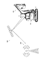
- FIG. 2 is a schematic diagram for explaining positioning of the shovel according to Embodiment 1 of the present invention
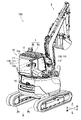
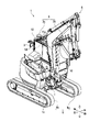
- FIG. 2 is a perspective view showing the excavator according to Embodiment 1 from the rear right.
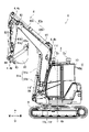
- 1 is a side view showing the excavator according to Embodiment 1 from the left side;
- FIG. 1 is a block diagram showing a shovel according to Embodiment 1;
- FIG. 2 is a perspective view showing the inside of the cabin of the excavator according to Embodiment 1.
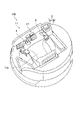
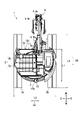
- FIG. FIG. 2 is a side view showing the excavator according to Embodiment 1 from the right side; 1 is a plan view showing the shovel according to Embodiment 1 from above;
- FIG. 1 is a perspective view showing the excavator according to Embodiment 1 from the front right.
- FIG. 3 is an enlarged view of the control unit of the excavator according to Embodiment 1.
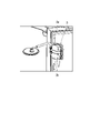
- FIG. 4 is an enlarged view of the receiver of the excavator according to Embodiment 1.
- FIG. 7 is a schematic diagram for explaining positioning of the shovel according to Embodiment 2 of the present invention;
- FIG. 5 is a block diagram showing a shovel according to Embodiment 2;
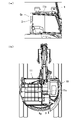
- (a) is a diagram showing a guide portion of a shovel according to a modification of the first embodiment.
- (b) is a diagram showing a rotating member of the excavator according to a modification of the first embodiment.
- FIG. 1 is a schematic diagram for explaining positioning of the excavator 100 according to the first embodiment.
- positioning of the excavator 100 is performed by applying, for example, RTK positioning (real-time kinematic positioning) as a positioning method using a global navigation satellite system (GNSS).
- RTK positioning real-time kinematic positioning
- GNSS global navigation satellite system
- the excavator 100 includes a first antenna 2, a receiver 3, a traveling body 9, and a revolving body 10. Moreover, the excavator 100 further includes a control unit 1 . Note that the illustration of the control unit 1 is omitted in FIG.
- Excavator 100 is an example of a construction machine. Specifically, in Embodiment 1, the excavator 100 is, for example, a hydraulic excavator.
- the traveling body 9 causes the shovel 100 to travel.
- the running body 9 is a crawler type running body.
- the revolving body 10 is arranged above the running body 9 .
- the revolving body 10 is rotatably supported by the running body 9 .
- the first antenna 2 is arranged on the revolving body 10 .
- the first antenna 2 is a Global Navigation Satellite System (GNSS) antenna.
- the first antenna 2 receives satellite signals from positioning satellites 300 (GNSS satellites).
- the first antenna 2 includes a first antenna 2a and a first antenna 2b.
- the first antenna 2a receives, for example, satellite signals from the positioning satellite 300 for calculating position information indicating the position of the first antenna 2a on the earth. That is, the first antenna 2a receives, for example, satellite signals from the positioning satellites 300 for calculating the position information of the revolving superstructure 10 on the earth.
- the position information of the revolving body 10 is represented by coordinates, for example.
- the first antenna 2b receives satellite signals for calculating the orientation of the revolving structure 10 from the positioning satellites 300, for example. That is, the first antenna 2b receives satellite signals for calculating the azimuth angle of the revolving structure 10 from the positioning satellites 300, for example.
- the receiving unit 3 receives specific information for specifying the position of the revolving structure 10 from the reference station 200 .
- the receiver 3 is also called a receiver, for example.
- Reference station 200 is an example of an “external device”. The specific information received from the reference station 200 will be described below.
- the reference station 200 is fixedly installed at a predetermined reference point. Specifically, the reference station 200 is installed, for example, around a work site where the excavator 100 performs work.
- the reference station 200 also includes, for example, an antenna for receiving satellite signals from the positioning satellite 300 and a communication device capable of wireless communication with the receiver 3 of the excavator 100 via a wireless communication network.
- the reference station 200 receives a satellite signal from the positioning satellite 300 and acquires the pseudorange from the positioning satellite 300 to the reference station 200 and the carrier wave phase (satellite positioning information) when the reference station 200 receives the satellite signal.
- the reference station 200 for example, each time the satellite positioning information is measured from the positioning satellite 300 or each time a set period elapses, specific information (calibration information) including the measured satellite positioning information and the position information of the reference point is generated. do.
- the reference station 200 then transmits the specific information to the receiver 3 of the excavator 100 .
- the control unit 1 performs positioning calculations based on satellite signals received by the first antenna 2a, and calculates position information (for example, coordinates) indicating the position of the revolving structure 10. Specifically, the control unit 1 receives a satellite signal from the positioning satellite 300, for example, and calculates the pseudorange from the positioning satellite 300 to the first antenna 2a and the carrier wave when the first antenna 2a receives the satellite signal. Get the phase and Then, the control unit 1 calculates the position information of the revolving body 10 based on the acquired pseudo-range and carrier wave phase.
- position information for example, coordinates
- control unit 1 performs positioning calculation based on, for example, the satellite signals received by the first antenna 2a and the satellite signals received by the first antenna 2b, and calculates information indicating the orientation of the revolving superstructure 10. . Specifically, the control unit 1 calculates, for example, the position information of the first antenna 2a and the position information of the first antenna 2b, and calculates the straight line connecting the position of the first antenna 2a and the position of the first antenna 2b. Calculate Then, the control unit 1 calculates information indicating the orientation of the revolving structure 10 based on the angle formed by the calculated straight line and the reference orientation. The reference direction is north, for example.
- the control unit 1 calibrates (corrects) the calculated position information and the calculated information indicating the orientation of the revolving structure 10 based on the specific information received by the receiver 3 . Therefore, the position information and the information indicating the orientation of the revolving superstructure 10 can be obtained with higher accuracy than when the position information and the information indicating the orientation of the revolving superstructure 10 are not calibrated based on the specific information. be able to. Further, in Embodiment 1, the control unit 1 continuously calculates the baseline solution between the excavator 100 as a mobile station and the reference station 200 . In the first embodiment, the baseline solution is a vector (baseline vector) connecting the excavator 100 to the reference station 200 .
- the positioning solution which is the positional information of the excavator 100, can be obtained in real time.
- a positioning solution is the position of the excavator 100 . That is, in Embodiment 1, the position of the excavator 100 can be obtained in real time.
- FIG. 2 is a perspective view showing the shovel 100 according to Embodiment 1 from the rear right.
- FIG. 3 is a left side view of the excavator 100 according to the first embodiment.
- FIG. 4 is a block diagram showing the excavator 100. As shown in FIG.
- the excavator 100 of the first embodiment includes a detection unit 4, an operation device 5, an operation lever 6, a second control valve 7, a working unit 8, a mirror 12, an engine 16.
- the operating device 5 and the operating lever 6 will be described later with reference to FIG.
- the work unit 8 executes work such as excavation work.
- the working part 8 is attached to the revolving body 10 .
- the working unit 8 includes a boom 81, a boom actuator 81a, an arm 82, an arm actuator 82a, a bucket 83, and an attachment actuator 83a.
- the boom 81 is supported by the revolving body 10 so as to be swingable around the first rotation fulcrum R1.
- the boom actuator 81a operates the boom 81. Specifically, the boom actuator 81a is driven by hydraulic fluid to swing the boom 81 about the first rotation fulcrum R1.
- the boom actuator 81a includes a boom cylinder 81b and a boom rod 81c.
- the boom cylinder 81b moves the boom rod 81c back and forth with hydraulic oil to operate the boom 81. As shown in FIG.
- the arm 82 is supported by the boom 81 so as to be swingable around the second rotation fulcrum R2.
- the arm actuator 82a operates the arm 82. Specifically, the arm actuator 82a is driven by hydraulic oil to swing the arm 82 about the second rotational fulcrum R2.
- the arm actuator 82a includes an arm cylinder 82b and an arm rod 82c.
- the arm cylinder 82b moves the arm rod 82c back and forth with hydraulic fluid to operate the arm 82. As shown in FIG.
- the bucket 83 is a kind of attachment.
- the bucket 83 is supported by the arm 82 so as to be swingable around the third rotation fulcrum R3.
- the attachment actuator 83 a operates the bucket 83 . Specifically, the attachment actuator 83a is driven by hydraulic fluid to swing the bucket 83 about the third rotation fulcrum R3.
- the attachment actuator 83a includes an attachment cylinder 83b and an attachment rod 83c.
- the attachment cylinder 83b advances and retracts the attachment rod 83c with hydraulic oil to operate the bucket 83 .
- the detection unit 4 detects the inclination of the excavator 100 and the attitude of the working unit 8 .
- the detection unit 4 includes, for example, an angle sensor 4a, an angle sensor 4b, an angle sensor 4c, and an angle sensor 4d.
- Angle sensor 4 a is included in control unit 1 .
- the angle sensor 4 a detects the tilt angle of the excavator 100 .
- Angle sensor 4 b is arranged on boom 81 .
- Angle sensor 4 b detects the rotation angle of boom 81 .
- Angle sensor 4 c is arranged on arm 82 .
- Angle sensor 4 c detects the rotation angle of arm 82 .
- Angle sensor 4 d is arranged on bucket link 84 that rotates bucket 83 .
- Angle sensor 4 d detects the rotation angle of bucket 83 .
- Each of the angle sensors 4a to 4d is, for example, an inertial measurement unit (IMU).
- IMU inertial measurement unit
- the control unit 1 further includes a control section 1a and a first control valve 1b in addition to the angle sensor 4a.
- the control unit 1a controls the operating device 5 and the engine 16, for example.
- the control unit 1a is, for example, an ECU (Electronic Control Unit).
- the control unit 1a also includes a processor such as a CPU (Central Processing Unit).
- the control unit 1a outputs a control signal based on, for example, position information of the revolving superstructure 10 specified by the specific information and information indicating the orientation of the revolving superstructure 10 .
- the control unit 1a outputs a control signal based on, for example, the position information of the revolving superstructure 10, the information indicating the orientation of the revolving superstructure 10, and the detection result of the detection unit 4, for example.
- the first control valve 1b converts the control signal output by the control section 1a into a hydraulic pressure signal and inputs the hydraulic pressure signal to the second control valve 7.
- the first control valve 1b is an example of a "switching valve".
- Fuel is supplied to the engine 16 from a fuel tank (not shown).
- the engine 16 drives a hydraulic pump (not shown) to deliver pressurized oil to the first control valve 1b or the second control valve 7 .
- Pressure oil is hydraulic oil under pressure.
- a second control valve 7 controls the flow of pressure oil.
- the second control valve 7 controls the flow rate and direction of the pressure oil to control a swing motor (not shown) for swinging the swing structure 10, a boom cylinder 81b, an arm cylinder 82b, and an attachment cylinder 83b.
- a travel motor not shown
- pressurized oil is supplied.
- the swing motor, boom cylinder 81b, arm cylinder 82b, attachment cylinder 83b, and travel motor are driven.
- the control unit 1a since the excavator 100 includes the detection unit 4, the reception unit 3, and the control unit 1, the control unit 1a receives the position information of the revolving superstructure 10, the information indicating the orientation of the revolving superstructure 10, and the detection unit Based on the detection result of 4, the working unit 8 can be automatically controlled based on predetermined design data. As a result, the operator of the excavator 100 can reduce the trouble of operating the excavator 100 . Specifically, for example, the control unit 1a automatically controls the working unit 8 so that the boom 81 and the bucket 83 operate in accordance with the operation of the arm 82, so that the operator's work can be reduced.
- the working unit 8 when the operator operates the working unit 8, the working unit 8 performs excavation work based on predetermined design data (excavation depth, etc.) at the positioning position (the position of the revolving structure 10). , the working unit 8 is automatically controlled. As a result, the depth is excavated according to the design data (design value).
- design data design value
- the revolving body 10 includes a cabin 11, a cockpit 11a, and a bonnet 15. 2 to 4, illustration of the cockpit 11a is omitted.
- a hood 15 covers the engine 16 of the excavator 100 .
- the bonnet 15 is positioned at the rear of the revolving body 10, for example. Specifically, the bonnet 15 is arranged on the opposite side of the cabin 11 from the working unit 8 .
- the operator of the excavator 100 sits in the cockpit 11a.
- the cabin 11 covers the cockpit 11a.
- the cabin 11 is supported by, for example, a frame (turning frame) of the revolving body 10 via anti-vibration rubber.
- “right” indicates the right when looking forward from the cabin 11 .
- “Left” indicates the left when viewed forward from the cabin 11 .
- the cabin 11 is arranged on the left side of the revolving body 10 .
- the cabin 11 includes a plurality of frames 11c and a plurality of plate members 11f.
- the plurality of frames 11c constitute a right side portion 11R, a left side portion 11L, a front portion 11F, and a rear portion 11B of the cabin 11, respectively.
- each of the plurality of frames 11c has an opening 11h. That is, the plurality of openings 11h are located in the right side portion 11R, the left side portion 11L, the front portion 11F, and the rear portion 11B of the cabin 11, respectively.
- the opening 11h functions as a window, for example. Note that the opening 11h of the frame 11c forming the front portion 11F of the cabin 11 is not shown in FIGS.
- a plurality of plate members 11f are attached to each of the plurality of openings 11h.
- the plate member 11f is, for example, a transparent member such as glass.
- the first antenna 2, the receiver 3, and the mirror 12 are arranged in the cabin 11.
- the first antenna 2 is arranged on the top surface 11 b of the cabin 11 . More specifically, each of first antenna 2 a and first antenna 2 b is arranged on top surface 11 b of cabin 11 via bracket 13 arranged on top surface 11 b of cabin 11 .
- the bracket 13 is provided with, for example, a screw groove, and each of the first antenna 2a and the first antenna 2b is fixed to the bracket 13 with a screw.
- the bracket 13 has, for example, a lattice shape and is made of metal.
- the area of the top surface 11b of the cabin 11 when viewed from above the revolving body 10 and the area of the bracket 13 when viewed from above the revolving body 10 are substantially the same.
- the first antenna 2a and the first antenna 2b are preferably arranged with a predetermined interval therebetween. Therefore, if the area of the top surface 11b when the revolving body 10 is viewed from above is small, by arranging the bracket 13 having an area larger than that of the top surface 11b on the top surface 11b, it is possible to The first antenna 2b can be arranged at a predetermined interval.
- the mirror 12 is arranged in the rear part of the cabin 11. Specifically, the mirror 12 is mounted on the rear side of the frame 11c forming the right side portion 11R of the cabin 11, for example, via a support 12a.
- the support 12a is, for example, a clamp.
- An operator of the excavator 100 checks the surroundings of the traveling body 9 through the mirror 12, for example.
- the receiver 3 has a substantially rectangular shape.
- a support 12a of the mirror 12 is provided with, for example, a screw groove, and the receiver 3 is fixed to the support 12a with screws. That is, the receiver 3 is attached to the frame 11c that constitutes the cabin 11 via the support 12a of the mirror 12.
- the receiver 3 can be arranged in the cabin 11 without providing the cabin 11 with a member different from the support 12a. That is, the receiver 3 can be easily attached to the cabin 11 .
- the running body 9 includes two crawlers.
- the left crawler may be referred to as “crawler 9a” and the right crawler may be referred to as “crawler 9b".
- the direction in which the crawler 9a extends and the direction in which the crawler 9b extends are substantially parallel to each other.
- FIG. 5 is a perspective view showing the interior of the cabin 11. As shown in FIG. In addition, in FIG. 5, the roof (top surface 11b) of the cabin 11 is omitted in order to make the drawing easier to see.
- an operating device 5 In the cabin 11, an operating device 5, a plurality of operating levers 6 for operating the working portion 8, and a plurality of traveling levers 17 for operating the traveling body 9 are arranged.
- the plurality of operating devices 5 and the travel lever 17 are arranged in front of the operator's seat 11a. Further, in Embodiment 1, the plurality of operation levers 6 are arranged on the right and left sides of the cockpit 11a, respectively.
- the operation device 5 receives various operations for the excavator 100 and displays various information about the excavator 100, for example.
- the operating device 5 includes a display section 5a and an operating section 5b.
- the display unit 5a is configured by a display such as a liquid crystal display or an organic EL display, for example.
- the display unit 5a displays various information about the excavator 100, for example.
- the operation unit 5b receives various operation instructions for the shovel 100.
- the operation unit 5b includes a plurality of operation switches in this embodiment.
- the operation switches are, for example, hard keys (for example, push buttons). Therefore, the operator can operate the operation part 5b while wearing protective equipment such as gloves.
- the operation unit 5b may be displayed as a GUI (Graphical User Interface) widget on the display unit 5a.
- GUI Graphic User Interface
- the display unit 5a displays the operation unit 5b as a widget, for example.
- the operation unit 5b may function as a touch panel included in the display unit 5a.
- Each of the plurality of operation levers 6 receives operations from the operator of the shovel 100.
- the operating lever 6 is an operating member for operating the excavator 100 .
- An operation signal is input to the second control valve 7 in response to the operation of the operation lever 6 by the operator of the excavator 100 .
- the second control valve 7 supplies pressure oil corresponding to the amount of operation of the operating lever 6 to the working portion 8 to operate the working portion 8 .
- FIG. 6 is a side view showing the excavator 100 from the right side.
- the revolving body 10 revolves around the revolving axis AX with respect to the traveling body 9 . Specifically, the revolving body 10 revolves with the rotary connecting member 14 with respect to the traveling body 9 . That is, the turning axis AX is substantially the same as the central axis of the rotary connecting member 14 .
- the rotary connecting member 14 is used, for example, as an oil passage between the revolving body 10 and the traveling body 9 .
- the rotary connecting member 14 includes, for example, a swivel joint.
- the receiving section 3 is arranged between the turning axis AX and the rear end 10b of the turning body 10 . Specifically, in the longitudinal direction of the revolving body 10, it is arranged between the revolving axis AX and the rear end 10b. Therefore, it is possible to prevent the receiving section 3 from coming into contact with an obstacle positioned behind the revolving body 10 . As a result, the safety of the excavator 100 can be further enhanced.
- the receiver 3 is arranged in the rear portion of the cabin 11 . Therefore, it is possible to prevent the operator of the shovel 100 from blocking the front or side field of view by the receiving unit 3 .
- the receiver 3 projects from the cabin 11 to the right of the revolving body 10 .
- the receiver 3 may protrude from the cabin 11 in the left direction of the revolving body 10 . That is, the receiver 3 protrudes from the cabin 11 to the left or right of the revolving body 10 . Therefore, the plate member 11f positioned on the back portion 11B of the cabin 11 and the receiving portion 3 do not overlap in the front-rear direction of the revolving body 10. As shown in FIG.
- the upper end 3u of the receiver 3 is positioned below the upper end 11d of the cabin 11, for example.
- the height of the upper end 3u of the receiver 3 may be substantially the same as the height of the upper end 11d of the cabin 11, for example. That is, the height of the upper end 3u of the receiving portion 3 is substantially the same as the height of the upper end 11d of the cabin 11, or the upper end 3u of the receiving portion 3 is located below the upper end 11d of the cabin 11. Therefore, it is possible to prevent the receiver 3 from contacting an obstacle located above the upper end 11 d of the cabin 11 . As a result, the safety of the excavator 100 can be further enhanced.
- the receiver 3 is located at a height where wireless communication between the receiver 3 and the reference station 200 (see FIG. 1) is not blocked by obstacles and at a position higher than the hood 15 .
- the receiver 3 may be attached to the top surface 11b of the cabin 11 .
- FIG. 7 is a plan view showing the excavator 100 from above.
- the length L1 from the front end 10c of the revolving body 10 to the rear end 10b of the revolving body 10 is less than or equal to the length L2 along the traveling direction of the traveling body 9, that is, the longitudinal direction D1.
- the length L2 of the running body 9 is also called the full length of the running body 9, for example. Therefore, even when the revolving body 10 revolves around the revolving axis AX, the receiving part 3 arranged between the revolving body 10 and the revolving body 10 is positioned outside the traveling body 9. It is possible to suppress contact with a positioned obstacle. As a result, the safety of the excavator 100 can be further enhanced.
- the length L1 of the revolving body 10 is equal to or less than the full width L3 of the running body 9 along the traveling direction of the running body 9, that is, the direction (lateral direction D2) substantially orthogonal to the longitudinal direction D1.
- the full width L3 is, for example, the length in the lateral direction D2 from the outer edge along the longitudinal direction D1 of the crawler 9a to the outer edge along the longitudinal direction D1 of the crawler 9b. Therefore, even when the revolving body 10 revolves around the revolving axis AX, the receiving part 3 arranged between the revolving body 10 and the revolving body 10 is positioned outside the traveling body 9. Contact with the obstacle located can be further suppressed. As a result, the safety of the excavator 100 can be further enhanced.
- FIG. 8 is a perspective view showing the excavator 100 from the front right.
- the control unit 1 is arranged behind the working section 8 and on the front side of the revolving body 10 in the front-rear direction of the revolving body 10 . Therefore, in the excavator 100, since there is a high possibility that there is a space behind the working part 8, the control unit 1 can be easily arranged. In addition, compared to the case where the control unit 1 is not arranged behind the working section 8 and on the front side of the revolving body 10, the size of the excavator 100 can be reduced.
- the hydraulic piping can be shortened.
- the hydraulic pipes are, for example, pipes connecting the hydraulic pump and the first control valve 1b, pipes connecting the first control valve 1b and the fuel tank, and pipes connecting the fuel tank and the hydraulic pump. As a result, the hydraulic piping can be easily arranged (routed).
- the control unit 1 further includes a housing 1c.
- the housing 1c is made of metal, for example.
- the housing 1c accommodates the controller 1a, the first control valve 1b, and the angle sensor 4a. Therefore, the controller 1a, the first control valve 1b, and the angle sensor 4a can be unitized. As a result, the trouble of arranging the control unit 1a, the first control valve 1b, and the angle sensor 4a on the revolving body 10 can be reduced.
- control unit 1a, the first control valve 1b, and the angle sensor 4a are housed in the housing 1c, it is possible to prevent the control unit 1a, the first control valve 1b, and the angle sensor 4a from being exposed. As a result, at least one of the control unit 1a, the first control valve 1b, and the angle sensor 4a can be prevented from contacting the obstacle or the working unit 8.
- FIG. 1a, the first control valve 1b, and the angle sensor 4a can be prevented from contacting the obstacle or the working unit 8.
- control unit 1 is arranged below the revolving body 10 .
- control unit 1 is arranged below the receiver 3 in the vertical direction of the revolving body 10 .
- the control unit 1 is often heavy. Therefore, the control unit 1 can be stably arranged. Moreover, the load on the mounting member (for example, bracket) for mounting the control unit 1 on the revolving body 10 can be reduced.
- the excavator 100 has wiring Cd that connects the receiver 3 and the controller 1 a of the control unit 1 .
- the wiring Cd is arranged along the cabin 11 . That is, the wiring Cd is routed along the cabin 11 .
- the wiring Cd is arranged, for example, along the upper end portion of the frame 11c that constitutes the right side portion 11R of the cabin 11 . Therefore, for example, the wire Cd can be guided by attaching the first support member 11g, such as a hook, to a screw groove provided in advance in the frame 11c. That is, for example, the wiring Cd can be easily arranged without newly performing a process for attaching the first support member 11g to the frame 11c (processing for further adding screw grooves to the frame 11c, etc.) to the cabin 11. .
- the first support member 11g is, for example, a hook as described above.
- the first support member 11g supports the wiring Cd. Therefore, the wiring Cd can be easily supported by the first support member 11g.
- the wiring Cd is arranged along the inner surface of the cabin 11, for example. Specifically, a portion of the wiring Cd is arranged along the inner surface of the cabin 11 . Therefore, it is possible to prevent the wiring Cd from coming into contact with the working portion 8 or the like. As a result, the safety of the excavator 100 can be further enhanced. All of the wiring Cd may be arranged along the outer surface of the cabin 11 . In this case, the first support member 11g is arranged outside the cabin 11 .
- the control unit 1 includes a second support member 1d that supports the wiring Cd.
- the second support member 1d is, for example, a hook.
- the second support member 1d is arranged in the housing 1c.
- the second support member 1d is arranged, for example, on the front side of the housing 1c in the longitudinal direction of the revolving body 10 and on the upper side of the housing 1c in the vertical direction of the revolving body 10 . Therefore, the wiring Cd can be bent around the housing 1c. As a result, the load on the wiring Cd due to the bending of the wiring Cd can be suppressed compared to the case where the control unit 1 does not include the second support member 1d.
- control unit 1 and the cabin 11 are arranged along the left-right direction of the revolving body 10 .
- the control unit 1 is arranged to the right of the cabin 11 . Therefore, it is easy to electrically connect the receiving unit 3, the operation device 5 arranged in the cabin 11, the operation lever 6 arranged in the cabin 11, and the working unit 8 to each other by wiring. .
- control unit 1 is arranged below the opening 11h of the frame 11c forming the cabin 11 in the vertical direction of the revolving structure 10 . Therefore, it is possible to prevent the control unit 1 from obstructing the field of view of the operator of the excavator 100 . As a result, the safety of the excavator 100 can be further enhanced.
- the receiver 3 , the control unit 1 , and the detector 4 are arranged along the longitudinal direction of the revolving body 10 .
- the receiver 3 , the control unit 1 , the angle sensor 4 a , the angle sensor 4 b , the angle sensor 4 c , and the angle sensor 4 b are arranged along the longitudinal direction of the revolving body 10 .
- the angle sensor 4a is included in the control unit 1 as described above.
- the first antenna 2 (the first antenna 2a and the first antenna 2b) is arranged between the revolving axis AX and the outer edge of the revolving body 10. be. That is, the first antenna 2 is arranged on the top surface 11b of the cabin 11, as described above. Therefore, it is possible to prevent the first antenna 2 from contacting an obstacle located behind the revolving body 10 . As a result, the safety of the excavator 100 can be further enhanced.
- FIG. 9 is an enlarged view of the control unit 1 of the shovel 100.
- the control unit 1a and the first control valve 1b are arranged along the longitudinal direction of the revolving body 10 inside the housing 1c.
- the control unit 1a is arranged in front of the first control valve 1b. Therefore, it is possible to prevent the control unit 1 from becoming large in the horizontal direction of the revolving body 10 .
- the control unit 1 can be miniaturized.
- the height of the control portion 1a is, for example, smaller than the height of the first control valve 1b.
- FIG. 10 is an enlarged view of the receiver 3 of the shovel 100.
- the receiver 3 includes a second antenna 3a and a main body 3b.
- the second antenna 3a receives specific information from, for example, the reference station 200 (see FIG. 1).
- the main body 3b acquires the specific information received by the second antenna 3a.
- the main body 3b transmits the acquired specific information to the control section 1a of the control unit 1 via the wiring Cd (see FIG. 8).
- the second antenna 3a and the main body 3b are integrally formed.
- FIG. 11 is a schematic diagram for explaining positioning of the excavator 100a.
- FIG. 12 is a block diagram showing the shovel 100a.
- the excavator 100a of the second embodiment differs from the excavator 100 of the first embodiment mainly in that the excavator 100a is positioned using a total station 400.
- FIG. In the following, differences of the second embodiment from the first embodiment will be mainly described, and descriptions of overlapping portions will be omitted.
- the total station 400 is used to perform positioning of the excavator 100a.
- the excavator 100 a includes a prism 30 .
- Prism 30 functions as a target for total station 400 .
- the prism 30 is arranged on the top surface 11b of the cabin 11, for example.
- Total station 400 is an example of an “external device”.
- the total station 400 measures the position of the prism 30 and transmits specific information as the measurement result to the receiver 3x. Then, the receiving section 3 x inputs the specific information received from the total station 400 to the control unit 1 .
- the control unit 1 identifies the position of the excavator 100 based on the identification information acquired via the receiver 3x. Then, the control unit 1 controls the first control valve 1b based on, for example, the position of the revolving superstructure 10 specified based on the specified information.
- RTK positioning is applied as a positioning method using the global positioning satellite system.
- other positioning methods may be applied.
- DGPS Different Global Positioning System
- DGPS Different Global Positioning System
- the receiving unit 3 acquires the specific information by directly performing wireless communication between the reference station 200 and the excavator 100 .
- the receiver 3 may acquire the specific information from the reference station 200 via a network such as the Internet.
- the frame 11c of the cabin 11 includes a plurality of plate members 11f.
- the cabin 11 does not have to include the plate member 11f. That is, the opening 11h of the frame 11c may be open.
- FIG. 13(a) is a diagram showing the guide part Gd of the excavator 100 according to the modification of the first embodiment.
- the revolving body 10 includes a guide portion Gd extending in the vertical direction of the revolving body 10 .
- the guide part Gd is arranged adjacent to the cabin 11 on the right side of the cabin 11 and on the rear side of the cabin 11 .
- the guide part Gd is, for example, a slide rail.
- the receiving section 3 can be moved along the guide section Gd, that is, along the vertical direction of the revolving body 10 .
- the receiver 3 is fixed by screws, for example. Therefore, the receiver 3 can be freely arranged in the vertical direction of the revolving body 10 .
- the receiver 3 when the receiver 3 communicates with the reference station 200, the receiver 3 can be arranged on the upper side. Further, when it is desired to avoid contact between an obstacle positioned above and the receiving section 3, the receiving section 3 can be arranged on the lower side.
- a space may be provided between the guide portion Gd and the cabin 11 , or the guide portion Gd may be adhered to the cabin 11 .
- FIG. 13(b) is a diagram showing a rotating member Hg of the excavator 100 according to another modification of the first embodiment.
- the revolving body 10 includes a rotating member Hg.
- the rotating member Hg is, for example, a hinge.
- the rotating member Hg is connected to the cabin 11 so as to be rotatable with respect to the cabin 11, for example.
- the rotating member Hg is arranged, for example, on the right side of the cabin 11 and on the rear side of the cabin 11 . That is, the rotating member Hg is attached to the rear side of the frame 11c that constitutes the right side portion 11R of the cabin 11, for example.
- the rotating member Hg couples the receiver 3 to the cabin 11 so as to be rotatable in the direction R with respect to the cabin 11 .
- the receiver 3 is horizontally rotatable. Therefore, the receiver 3 can be freely arranged in the horizontal direction.
- the second antenna 3a and the main body 3b of the receiving section 3 are integrally formed.
- the second antenna 3a and the main body 3b may be separate bodies. Therefore, the second antenna 3a and the main body 3b may be arranged at different positions.
- the second antenna 3 a may be arranged outside the cabin 11 and the main body 3 b may be arranged inside the bonnet 15 or inside the cabin 11 . Therefore, the possibility of the main body 3b contacting an obstacle or the working part 8 can be suppressed. As a result, the safety of the excavator 100 can be further enhanced.
- the prism 30 is arranged on the top surface 11b of the cabin 11 in the second embodiment.
- the position of the prism 30 is not particularly limited.
- the prism 30 may be arranged on the upper part of a post installed in the soil removal mechanism 9 c included in the traveling body 9 .
- the soil discharging mechanism 9c is used, for example, for soil discharging work such as earth and sand, and ground leveling work such as developed land and roads.
- the excavator 100 was taken as an example of the construction machine, but the construction machine is not limited to the excavator 100.
- a construction machine is, for example, a loader, such as a wheel loader, or a carrier.
- a cabin-type construction machine was explained, but the present invention can also be applied to a canopy-type construction machine.
- a canopy-type construction machine by arranging the receiving unit 3 at a predetermined position on the canopy's support or eaves, as with a cabin-type construction machine, while avoiding contact with surrounding obstacles. , the good communication with the reference station 200 or the total station 400 can be ensured.
- the present invention relates to construction machinery and has industrial applicability.
Landscapes
- Engineering & Computer Science (AREA)
- Mining & Mineral Resources (AREA)
- Civil Engineering (AREA)
- General Engineering & Computer Science (AREA)
- Structural Engineering (AREA)
- Remote Sensing (AREA)
- Radar, Positioning & Navigation (AREA)
- Mechanical Engineering (AREA)
- Computer Security & Cryptography (AREA)
- Computer Networks & Wireless Communication (AREA)
- Physics & Mathematics (AREA)
- General Physics & Mathematics (AREA)
- Operation Control Of Excavators (AREA)
- Component Parts Of Construction Machinery (AREA)
- Variable-Direction Aerials And Aerial Arrays (AREA)
- Position Fixing By Use Of Radio Waves (AREA)
Abstract
Description
まず、図1を参照して、本発明の実施形態1に係るショベル100の測位について説明する。図1は、実施形態1に係るショベル100の測位を説明するための概略図である。実施形態1において、全球測位衛星システム(Global Navigation Satellite System:GNSS)を用いた測位方法として、例えば、RTK測位(リアルタイムキネマティック測位)を適用して、ショベル100の測位が実行される。
図11及び図12を参照して、実施形態2に係るショベル100aについて説明する。図11は、ショベル100aの測位を説明するための概略図である。図12は、ショベル100aを示すブロック図である。ショベル100aがトータルステーション400を用いて測位される点で、実施形態2のショベル100aは、実施形態1のショベル100と主に異なる。以下、実施形態2が実施形態1と異なる点を主に説明し、重複部分については説明を省略する。
1 制御ユニット
1a 制御部
1b 第1コントロールバルブ(切替弁)
2 第1アンテナ
3 受信部
3a 第2アンテナ
3b 本体
8 作業部
9 走行体
10 旋回体
11 キャビン
200 基準局(外部装置)
400 トータルステーション(外部装置)
AX 旋回軸線
Gd ガイド部
Hg 回動部材
Claims (21)
- 走行体と、
前記走行体の上部に配置され、前記走行体に対して旋回軸線の回りに旋回する旋回体と、
前記旋回体の位置を特定するための特定情報を外部装置から受信する受信部と
を備え、
前記受信部は、前記旋回軸線と前記旋回体の後端との間に配置される、建設機械。 - 前記旋回体は、キャビンを含み、
前記受信部は、前記キャビンのうちの後方部分に配置される、請求項1に記載の建設機械。 - 前記旋回体の前端から後端までの長さは、前記走行体の進行方向に沿った長さ以下である、請求項1または請求項2に記載の建設機械。
- 前記旋回体の前端から後端までの長さは、前記走行体の進行方向に略直交する方向に沿った、前記走行体の全幅以下である、請求項1から請求項3のいずれか1項に記載の建設機械。
- 前記旋回体は、キャビンを含み、
前記受信部は、前記旋回体の左方向又は右方向に、前記キャビンから突出する、請求項1から請求項4のいずれか1項に記載の建設機械。 - 前記旋回体は、キャビンを含み、
前記受信部は、前記キャビンに配置され、
前記受信部の上端の高さは前記キャビンの上端の高さに略同一、又は前記受信部の上端は前記キャビンの上端より下方に位置する、請求項1から請求項5のいずれか1項に記載の建設機械。 - 前記旋回体に取り付けられ、作業を実行する作業部と、
前記特定情報よって特定された前記旋回体の位置に基づいて、前記作業部を制御する制御ユニットと
をさらに備え、
前記制御ユニットは、前記作業部の後方であって、前記旋回体のうちの前側に配置される、請求項1から請求項6のいずれか1項に記載の建設機械。 - 前記制御ユニットは、
前記特定情報によって特定された前記旋回体の位置に基づいて制御信号を出力する制御部と、
前記制御信号を油圧信号に変換し、前記油圧信号に基づいて前記作業部を制御する切替弁と
を含み、
前記制御部と前記切替弁とは、前記旋回体の前後方向に沿って配置される、請求項7に記載の建設機械。 - 前記旋回体は、キャビンを含み、
前記制御ユニットと前記キャビンとは、前記旋回体の左右方向に沿って配置される、請求項7または請求項8のいずれか1項に記載の建設機械。 - 前記旋回体は、キャビンを含み、
前記キャビンは、前記キャビンの右側面部又は左側面部に位置する開口を有し、
前記制御ユニットは、前記開口より下方に配置される、請求項7から請求項9のいずれか1項に記載の建設機械。 - 前記旋回体は、キャビンを含み、
前記受信部と前記制御ユニットとを接続する配線を有し、
前記配線は、前記キャビンに沿って配置される、請求項8から請求項10のいずれか1項に記載の建設機械。 - 前記配線は、前記キャビンの内面に沿って配置される、請求項11に記載の建設機械。
- 前記キャビンは、前記配線を支持する第1支持部材を含む、請求項11または請求項12に記載の建設機械。
- 前記制御ユニットは、
前記制御部及び前記切替弁を収容する筐体と、
前記筐体に配置され、前記配線を支持する第2支持部材と
を含む、請求項11から請求項13のいずれか1項に記載の建設機械。 - 前記作業部の姿勢を検出する検出部をさらに備える、請求項7から請求項14のいずれか1項に記載の建設機械。
- 前記受信部、前記制御ユニット、及び前記検出部は、前記旋回体の前後方向に沿って配置される、請求項15に記載の建設機械。
- 衛星から、前記旋回体の位置を示す位置情報を受信する第1アンテナをさらに備え、
前記特定情報に基づいて、前記位置情報が較正される、請求項1から請求項16のいずれか1項に記載の建設機械。 - 前記旋回体は、キャビンを含み、
前記第1アンテナは、前記キャビンの天面に配置される、請求項17に記載の建設機械。 - 前記旋回体は、キャビンを含み、
前記キャビンは、前記旋回体の上下方向に延びるガイド部を含み、
前記受信部は、前記ガイド部に沿って昇降可能に支持される、請求項1から請求項18のいずれか1項に記載の建設機械。 - 前記旋回体は、キャビンと、前記受信部を前記キャビンに連結させる回動部材とを含み、
前記回動部材は、前記キャビンに対して回動可能に、前記キャビンに連結される、請求項1から請求項19のいずれか1項に記載の建設機械。 - 前記受信部は、
前記特定情報を受信する第2アンテナと、
前記第2アンテナが受信した前記特定情報を取得する本体と
を含み、
前記本体と前記第2アンテナとは、異なる位置に配置される、請求項1から請求項20のいずれか1項に記載の建設機械。
Priority Applications (4)
| Application Number | Priority Date | Filing Date | Title |
|---|---|---|---|
| KR1020237025893A KR20230139432A (ko) | 2021-02-05 | 2022-02-04 | 건설 기계 |
| US18/275,414 US20240117606A1 (en) | 2021-02-05 | 2022-02-04 | Construction Machine |
| EP22749826.8A EP4290019A4 (en) | 2021-02-05 | 2022-02-04 | CONSTRUCTION EQUIPMENT |
| CN202280013460.0A CN116829789A (zh) | 2021-02-05 | 2022-02-04 | 工程机械 |
Applications Claiming Priority (2)
| Application Number | Priority Date | Filing Date | Title |
|---|---|---|---|
| JP2021017432A JP7482575B2 (ja) | 2021-02-05 | 2021-02-05 | 建設機械 |
| JP2021-017432 | 2021-02-05 |
Publications (1)
| Publication Number | Publication Date |
|---|---|
| WO2022168955A1 true WO2022168955A1 (ja) | 2022-08-11 |
Family
ID=82741596
Family Applications (1)
| Application Number | Title | Priority Date | Filing Date |
|---|---|---|---|
| PCT/JP2022/004516 Ceased WO2022168955A1 (ja) | 2021-02-05 | 2022-02-04 | 建設機械 |
Country Status (6)
| Country | Link |
|---|---|
| US (1) | US20240117606A1 (ja) |
| EP (1) | EP4290019A4 (ja) |
| JP (3) | JP7482575B2 (ja) |
| KR (1) | KR20230139432A (ja) |
| CN (1) | CN116829789A (ja) |
| WO (1) | WO2022168955A1 (ja) |
Families Citing this family (5)
| Publication number | Priority date | Publication date | Assignee | Title |
|---|---|---|---|---|
| EP4685294A1 (en) * | 2023-03-28 | 2026-01-28 | Hitachi Construction Machinery Co., Ltd. | Work machinery and operation assistance system for work machinery |
| KR20250123030A (ko) * | 2024-02-07 | 2025-08-14 | 얀마 홀딩스 주식회사 | 작업 차량 |
| JP2025142995A (ja) * | 2024-03-18 | 2025-10-01 | ヤンマーホールディングス株式会社 | 作業機械 |
| JP2025171325A (ja) * | 2024-05-09 | 2025-11-20 | ヤンマーホールディングス株式会社 | 作業機械 |
| JP2025171324A (ja) * | 2024-05-09 | 2025-11-20 | ヤンマーホールディングス株式会社 | 作業機械 |
Citations (5)
| Publication number | Priority date | Publication date | Assignee | Title |
|---|---|---|---|---|
| JP5873607B1 (ja) | 2015-03-27 | 2016-03-01 | 株式会社小松製作所 | 作業機械の較正装置、及び作業機械の作業機パラメータの較正方法 |
| JP2020007700A (ja) * | 2018-07-02 | 2020-01-16 | ヤンマー株式会社 | 旋回作業車 |
| JP2020139328A (ja) * | 2019-02-28 | 2020-09-03 | 日立建機株式会社 | 建設機械 |
| JP2020165235A (ja) * | 2019-03-29 | 2020-10-08 | 住友建機株式会社 | ショベル |
| WO2021019901A1 (ja) * | 2019-07-31 | 2021-02-04 | ヤンマーパワーテクノロジー株式会社 | 建設機械、アンテナ取付方法、及びアンテナ取付構造 |
Family Cites Families (15)
| Publication number | Priority date | Publication date | Assignee | Title |
|---|---|---|---|---|
| JPS5873607U (ja) | 1981-11-13 | 1983-05-18 | 株式会社日立製作所 | アンテナ端子 |
| JP4121642B2 (ja) * | 1998-11-13 | 2008-07-23 | 株式会社トプコン | 建設機械制御システム |
| US6253160B1 (en) * | 1999-01-15 | 2001-06-26 | Trimble Navigation Ltd. | Method and apparatus for calibrating a tool positioning mechanism on a mobile machine |
| JP2006056280A (ja) * | 2004-08-17 | 2006-03-02 | Yanmar Co Ltd | 作業車両 |
| JP5280258B2 (ja) * | 2009-03-16 | 2013-09-04 | 株式会社トプコン | 測量システム |
| ES2373817B1 (es) * | 2010-07-30 | 2012-09-06 | Benjamín Cebrián Romo | Dispositivo de control de dilución de mineral. |
| JP2013087466A (ja) * | 2011-10-17 | 2013-05-13 | Kobelco Contstruction Machinery Ltd | キャブおよび建設機械 |
| KR101656196B1 (ko) * | 2014-10-24 | 2016-09-08 | 가부시키가이샤 고마쓰 세이사쿠쇼 | 캡 및 작업 기계 |
| US9988787B1 (en) * | 2016-03-10 | 2018-06-05 | Robo Industries, Inc. | System for determining position of a vehicle |
| WO2018179409A1 (ja) * | 2017-03-31 | 2018-10-04 | 株式会社小松製作所 | 作業車両 |
| WO2019003266A1 (ja) * | 2017-06-26 | 2019-01-03 | 株式会社小松製作所 | 建設機械 |
| US10907326B2 (en) * | 2017-08-11 | 2021-02-02 | Deere & Company | Vision system for monitoring a work tool of a work vehicle |
| JP6956688B2 (ja) * | 2018-06-28 | 2021-11-02 | 日立建機株式会社 | 作業機械 |
| JP7301514B2 (ja) * | 2018-09-21 | 2023-07-03 | 日立建機株式会社 | 座標変換システム及び作業機械 |
| JP7137534B2 (ja) * | 2019-06-28 | 2022-09-14 | 株式会社日立建機ティエラ | 建設機械 |
-
2021
- 2021-02-05 JP JP2021017432A patent/JP7482575B2/ja active Active
-
2022
- 2022-02-04 CN CN202280013460.0A patent/CN116829789A/zh active Pending
- 2022-02-04 EP EP22749826.8A patent/EP4290019A4/en active Pending
- 2022-02-04 WO PCT/JP2022/004516 patent/WO2022168955A1/ja not_active Ceased
- 2022-02-04 KR KR1020237025893A patent/KR20230139432A/ko active Pending
- 2022-02-04 US US18/275,414 patent/US20240117606A1/en active Pending
-
2024
- 2024-04-24 JP JP2024070219A patent/JP2024097811A/ja active Pending
-
2025
- 2025-02-05 JP JP2025017965A patent/JP2025065325A/ja active Pending
Patent Citations (5)
| Publication number | Priority date | Publication date | Assignee | Title |
|---|---|---|---|---|
| JP5873607B1 (ja) | 2015-03-27 | 2016-03-01 | 株式会社小松製作所 | 作業機械の較正装置、及び作業機械の作業機パラメータの較正方法 |
| JP2020007700A (ja) * | 2018-07-02 | 2020-01-16 | ヤンマー株式会社 | 旋回作業車 |
| JP2020139328A (ja) * | 2019-02-28 | 2020-09-03 | 日立建機株式会社 | 建設機械 |
| JP2020165235A (ja) * | 2019-03-29 | 2020-10-08 | 住友建機株式会社 | ショベル |
| WO2021019901A1 (ja) * | 2019-07-31 | 2021-02-04 | ヤンマーパワーテクノロジー株式会社 | 建設機械、アンテナ取付方法、及びアンテナ取付構造 |
Non-Patent Citations (1)
| Title |
|---|
| See also references of EP4290019A4 |
Also Published As
| Publication number | Publication date |
|---|---|
| JP2025065325A (ja) | 2025-04-17 |
| EP4290019A4 (en) | 2025-01-08 |
| JP7482575B2 (ja) | 2024-05-14 |
| US20240117606A1 (en) | 2024-04-11 |
| KR20230139432A (ko) | 2023-10-05 |
| CN116829789A (zh) | 2023-09-29 |
| EP4290019A1 (en) | 2023-12-13 |
| JP2022120503A (ja) | 2022-08-18 |
| JP2024097811A (ja) | 2024-07-19 |
Similar Documents
| Publication | Publication Date | Title |
|---|---|---|
| JP7482575B2 (ja) | 建設機械 | |
| JP6987186B2 (ja) | 表示システム、建設機械、及び表示方法 | |
| US8886416B2 (en) | Hydraulic shovel operability range display device and method for controlling same | |
| US9663917B2 (en) | Work vehicle, bucket device, and method for obtaining tilt angle | |
| US9410305B2 (en) | Excavation control system for hydraulic excavator | |
| JP7804600B2 (ja) | 旋回作業車 | |
| JP6782256B2 (ja) | 油圧ショベル | |
| US9689145B1 (en) | Work vehicle and method for obtaining tilt angle | |
| CN111183551A (zh) | 作业车辆用天线单元以及作业车辆 | |
| KR20180037132A (ko) | 작업 기계의 표시 시스템 및 작업 기계 | |
| CN113874862A (zh) | 工程机械 | |
| JP6845810B2 (ja) | 油圧ショベルおよび油圧ショベルの較正方法 | |
| JP7424960B2 (ja) | 情報取得システムおよび情報取得方法 | |
| KR102679015B1 (ko) | 작업 기계의 측위 시스템, 작업 기계 및 작업 기계의 측위 방법 | |
| KR20150079956A (ko) | 측정 지그 | |
| CN112334618B (zh) | 液压挖掘机 | |
| US20230257967A1 (en) | Revolving work vehicle, and method for detecting position of working end of revolving work vehicle | |
| JP7419119B2 (ja) | 作業機械 | |
| WO2022255362A1 (ja) | 電子制御装置 | |
| JP2023165026A (ja) | 移植機 | |
| EP4145179B1 (en) | Commissioning a construction vehicle for machine control | |
| JP6995040B2 (ja) | 水田作業機 |
Legal Events
| Date | Code | Title | Description |
|---|---|---|---|
| 121 | Ep: the epo has been informed by wipo that ep was designated in this application |
Ref document number: 22749826 Country of ref document: EP Kind code of ref document: A1 |
|
| WWE | Wipo information: entry into national phase |
Ref document number: 18275414 Country of ref document: US |
|
| WWE | Wipo information: entry into national phase |
Ref document number: 202280013460.0 Country of ref document: CN |
|
| NENP | Non-entry into the national phase |
Ref country code: DE |
|
| ENP | Entry into the national phase |
Ref document number: 2022749826 Country of ref document: EP Effective date: 20230905 |