WO2022172805A1 - 車両用窓ガラス - Google Patents
車両用窓ガラス Download PDFInfo
- Publication number
- WO2022172805A1 WO2022172805A1 PCT/JP2022/003762 JP2022003762W WO2022172805A1 WO 2022172805 A1 WO2022172805 A1 WO 2022172805A1 JP 2022003762 W JP2022003762 W JP 2022003762W WO 2022172805 A1 WO2022172805 A1 WO 2022172805A1
- Authority
- WO
- WIPO (PCT)
- Prior art keywords
- region
- glass plate
- regions
- pair
- glass
- Prior art date
- Legal status (The legal status is an assumption and is not a legal conclusion. Google has not performed a legal analysis and makes no representation as to the accuracy of the status listed.)
- Ceased
Links
Images
Classifications
-
- B—PERFORMING OPERATIONS; TRANSPORTING
- B60—VEHICLES IN GENERAL
- B60S—SERVICING, CLEANING, REPAIRING, SUPPORTING, LIFTING, OR MANOEUVRING OF VEHICLES, NOT OTHERWISE PROVIDED FOR
- B60S1/00—Cleaning of vehicles
- B60S1/02—Cleaning windscreens, windows or optical devices
- B60S1/023—Cleaning windscreens, windows or optical devices including defroster or demisting means
- B60S1/026—Cleaning windscreens, windows or optical devices including defroster or demisting means using electrical means
-
- H—ELECTRICITY
- H05—ELECTRIC TECHNIQUES NOT OTHERWISE PROVIDED FOR
- H05B—ELECTRIC HEATING; ELECTRIC LIGHT SOURCES NOT OTHERWISE PROVIDED FOR; CIRCUIT ARRANGEMENTS FOR ELECTRIC LIGHT SOURCES, IN GENERAL
- H05B3/00—Ohmic-resistance heating
- H05B3/84—Heating arrangements specially adapted for transparent or reflecting areas, e.g. for demisting or de-icing windows, mirrors or vehicle windshields
- H05B3/86—Heating arrangements specially adapted for transparent or reflecting areas, e.g. for demisting or de-icing windows, mirrors or vehicle windshields the heating conductors being embedded in the transparent or reflecting material
-
- H—ELECTRICITY
- H05—ELECTRIC TECHNIQUES NOT OTHERWISE PROVIDED FOR
- H05B—ELECTRIC HEATING; ELECTRIC LIGHT SOURCES NOT OTHERWISE PROVIDED FOR; CIRCUIT ARRANGEMENTS FOR ELECTRIC LIGHT SOURCES, IN GENERAL
- H05B2203/00—Aspects relating to Ohmic resistive heating covered by group H05B3/00
- H05B2203/011—Heaters using laterally extending conductive material as connecting means
-
- H—ELECTRICITY
- H05—ELECTRIC TECHNIQUES NOT OTHERWISE PROVIDED FOR
- H05B—ELECTRIC HEATING; ELECTRIC LIGHT SOURCES NOT OTHERWISE PROVIDED FOR; CIRCUIT ARRANGEMENTS FOR ELECTRIC LIGHT SOURCES, IN GENERAL
- H05B2203/00—Aspects relating to Ohmic resistive heating covered by group H05B3/00
- H05B2203/013—Heaters using resistive films or coatings
-
- H—ELECTRICITY
- H05—ELECTRIC TECHNIQUES NOT OTHERWISE PROVIDED FOR
- H05B—ELECTRIC HEATING; ELECTRIC LIGHT SOURCES NOT OTHERWISE PROVIDED FOR; CIRCUIT ARRANGEMENTS FOR ELECTRIC LIGHT SOURCES, IN GENERAL
- H05B2203/00—Aspects relating to Ohmic resistive heating covered by group H05B3/00
- H05B2203/016—Heaters using particular connecting means
Definitions
- the present invention relates to vehicle window glass.
- An anti-fogging defogger is generally formed on the rear glass of an automobile.
- a defogger usually includes a pair of busbars extending along both sides of the rear glass, and a plurality of heating wires extending in parallel to connect the busbars.
- the bus bar is provided with connection terminals for applying current (for example, Patent Documents 1 and 2).
- a vehicle window glass includes a curved glass plate having a first surface and a second surface, and a curved glass plate formed on the first surface and extending along any two sides of the glass plate. a pair of arranged busbars, a plurality of heating wires formed on the first surface and arranged in parallel so as to connect the pair of busbars, connection terminals respectively arranged on the pair of busbars; and each of the pair of bus bars has a first region in which the connection terminal is arranged and a second region other than the first region, and the first region and the second region are connected along the side, and the resistance value per unit area of the first region is smaller than the resistance value per unit area of the second region.
- the thickness of the first region may be greater than the thickness of the second region.
- the first region and the second region may be formed of different materials, and the resistance value of the material forming the first region is the same as that of the material forming the second region. It can be smaller than the resistance value.
- the width of the first region can be substantially the same as the width of the second region, or can be smaller than the width of the second region.
- the first surface of the glass plate may constitute a concave surface.
- the vehicle window glass of the present invention it is possible to suppress localized high temperature at the locations where the connection terminals are provided.
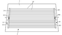
- FIG. 1 is a plan view of a vehicle window glass according to an embodiment of the present invention
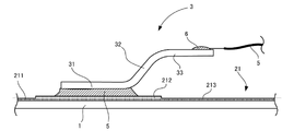
- FIG. FIG. 4 is a cross-sectional view of a window glass to which connection terminals are attached;
- FIG. 1 is a plan view of this vehicle window glass.
- this vehicle window glass includes a glass plate 1 curved so as to protrude outward of the vehicle, a defogger 2 laminated on the surface of the glass plate 1 on the inner side of the vehicle, and the defogger 2 and a pair of connection terminals 3 attached by solder 4 .
- a conductive cable 5 (see FIG. 2) extending from the interior of the vehicle is attached to each connection terminal 3 , and current supplied from the conductive cable 5 is supplied to the defogger 2 via the connection terminal 3 .
- Each member will be described below.
- the glass plate 1 is formed in a rectangular shape, and a known glass plate for automobiles can be used.
- the glass plate 1 may be heat-absorbing glass, general clear glass or green glass, or UV green glass.
- a glass plate 1 needs to achieve a visible light transmittance that meets the safety standards of the countries where automobiles are used.
- the solar absorptance, visible light transmittance, etc. can be adjusted so as to satisfy safety standards.
- An example of the composition of the clear glass and an example of the composition of the heat-absorbing glass are shown below.
- the composition of the heat-absorbing glass is, for example, based on the composition of the clear glass, the ratio of total iron oxide (T-Fe 2 O 3 ) converted to Fe 2 O 3 is 0.4 to 1.3% by mass, and CeO 2 is 0 to 2% by mass, the ratio of TiO 2 is 0 to 0.5% by mass, and the framework components of the glass (mainly SiO 2 and Al 2 O 3 ) are T—Fe 2 O 3 and CeO. 2 and TiO 2 increments.
- the type of glass plate 1 is not limited to clear glass or heat-absorbing glass, and can be appropriately selected according to the embodiment.
- the thickness of the glass plate 1 according to this embodiment does not have to be particularly limited.
- the thickness of the glass plate 1 is preferably 2.2 to 5.1 mm, more preferably 2.4 to 3.8 mm, and more preferably 2.7 to 3.2 mm. is particularly preferred.
- such a glass plate 1 may be a laminated glass in which an intermediate film such as a resin is sandwiched between a plurality of glasses, in addition to a single glass plate.
- FIG. 2 is a cross-sectional view of a window glass provided with connection terminals.
- the defogger 2 includes a pair of first and second power supply bus bars 21 and 22 extending vertically along both side edges of the glass plate 1 .
- a plurality of horizontally extending heating wires 23 are arranged in parallel with each other at predetermined intervals between the bus bars 21 and 22 .
- connection terminal 3 which will be described later, is arranged near the center of each of the bus bars 21 and 22.
- a current is supplied to the connection terminal 3 attached to the first bus bar 21 via the conductive cable 5 , and the connection terminal 3 attached to the second bus bar 22 is grounded via the conductive cable 5 .
- the heating wire 23 when current is supplied to the defogger 2, the heating wire 23 generates heat for defogging.
- the first bus bar 21 is configured by connecting three regions so as to be aligned in the vertical direction. That is, from top to bottom, an upper area (second area) 211, a central area (first area) 212, and a lower area (second area) 213 are arranged side by side. Each of the regions 211 to 213 has substantially the same width, and the vertical length of the central region 213 is shorter than that of the upper region 211 and the lower region 213 . Also, the thickness of the central region 212 is thicker than the upper region 211 and the lower region 213 . As will be described later, the connection terminals 3 are fixed to the central region 212 by soldering.
- the thickness of the central region 212 can be an integral multiple of the thicknesses of the other regions 211 and 213, such as double or triple. Specifically, the thickness of the central region 212 is, for example, preferably 5 to 100 ⁇ m, more preferably 10 to 30 ⁇ m. On the other hand, the thickness of the upper region 211 and the lower region 213 is, for example, preferably 3 to 50 ⁇ m, more preferably 5 to 20 ⁇ m. The thickness of upper region 211 and lower region 213 may be the same or different. Also, the thickness of the heating wire 23 is not particularly limited, but can be the same as the thickness of the upper region 211 and the lower region 213 .
- the length of the central region 212 is not particularly limited, but is, for example, 5 to 70%, preferably 10 to 50%, more preferably 15 to 25% of the total length of each busbar 21, 22. be able to.
- Each of the bus bars 21 and 22 and the heating wire 23 is formed by, for example, applying conductive silver paste, copper paste, or aluminum paste to the surface of the glass plate 1 on the inside of the vehicle by screen printing or the like, and then firing the paste. formed by However, the material forming the defogger 2 is not limited to these materials and can be selected as appropriate.
- connection terminal 3 Next, the connection terminal 3 will be described. Although the connection terminals 3 attached to the first bus bar 21 will be described below, the connection terminals 3 attached to the second bus bar 22 have the same configuration.
- connection terminals 3 are integrally formed by bending a conductive material such as plate-like metal, and are installed on the bus bars 21 and 22 of the defogger 2.
- a plate-shaped installation portion 31 is provided.
- the installation portion 31 is formed in a rectangular shape, and the lower surface thereof is fixed to the central regions 212 and 222 of the busbars 21 and 22 via the solder 5 .
- the solder 5 may be either lead-free solder or lead-containing solder.
- lead-free solder for example, indium-based or bismuth-based lead-free solder can be used.
- a plate-like standing portion 32 standing obliquely upward is integrally connected to the rear end portion of the installation portion 31 .
- the standing portion 32 is formed in a rectangular shape and stands at an angle of approximately 30 degrees with respect to the installation portion 31 .
- the angle of the standing portion 32 with respect to the installation portion 31 is not particularly limited, it is preferably 10 to 90 degrees, for example.
- a plate-like connecting portion 33 extending horizontally toward the rear is integrally connected to the upper end portion of the standing portion 32 .
- the connection portion 33 is formed in a rectangular shape in a plan view and narrower than the installation portion 31.
- an adhesive member 6 such as solder or a conductive adhesive. , is fixed.
- the paste for the defogger 2 is printed on one surface of the flat glass plate 1 .
- paste is printed twice or more on the central regions 212 and 222 of the bus bars 21 and 22 to make them thicker than the upper regions 211 and 221 and the lower regions 213 and 223 .
- the glass plate 1 is carried into a heating furnace to heat the glass plate 1 to near the softening point, and the paste printed on the glass plate 1 is fired to form the defogger 2 . Subsequently, the glass plate 1 carried out from the heating furnace is pressed to bend the glass plate 1 into a desired shape.
- the surface on which the defogger 2 is formed becomes a concave surface.
- the connection terminals 3 are attached to the bus bars 21 and 22, thereby completing the window glass according to the present embodiment.
- the method of forming the glass plate 1 is not particularly limited, and in addition to the above-described press forming, the glass plate 1 can be formed by a self-weight bending method in which the glass plate 1 is bent by its own weight.
- the windowpane according to this embodiment can provide the following effects.
- the central regions 212 and 222 where the connection terminals 3 are arranged may be locally heated to a high temperature because current is applied intensively.
- the thickness of the central regions 212 and 222 where the connection terminals 3 are arranged is increased, so the resistance per unit area of these regions 212 and 222 is reduced. Therefore, even if the current is applied intensively, the generated heat can be reduced, so that the central region can be prevented from becoming locally hot.
- the defogger 2 is made of silver (electric resistivity: 1.6 ⁇ 10 ⁇ 8 ⁇ m), the width of the defogger is 30 mm, and the thickness of the central regions 212 and 222 is about 20 ⁇ m, the central The resistance value per unit area of the regions 212 and 222 is about 1.5 ⁇ /m 2 (the resistance value per bus bar unit length is about 0.45 ⁇ /dm), and the heat generation amount per unit area is 114 W/m 2 .
- the thickness of the upper regions 211, 221 and the lower regions 213, 223 is about 10 ⁇ m, the resistance per unit area of these regions is about 2.0 ⁇ /m 2 (per unit length of bus bar).
- the resistance value is about 0.90 ⁇ /dm), and the heat generation amount per unit area is 152 W/m 2 . Therefore, the amount of heat generated per unit area in the central regions 212 and 222 can be made smaller than in the other regions, and local high temperatures can be suppressed.
- the metal such as silver forming the busbars 21 and 22 has a higher heat reflectance than the glass plate 1, so it is less heated than the glass plate 1 when heated in a heating furnace. Therefore, when slowly cooled, a difference in contraction occurs between the busbars 21 and 22 and the glass plate 1, and the glass plate 1 is distorted in the vicinity of the busbars 21 and 22, which may cause perspective distortion. On the other hand, for example, it is conceivable to widen the width of the area in which the connection terminal 3 is provided in the busbars 21 and 22, but there is a problem that the area in which perspective distortion occurs becomes wide.
- the width of the central regions 212, 222 is made substantially the same as that of the upper regions 211, 221 and the lower regions 213, 223, so that the region where perspective distortion occurs can be reduced.
- the central regions 212 and 222 can be made wider than the other regions, even in such a case, if the central regions 212 and 222 are made thicker than the other regions, the central regions 212 and 222 can be made wider. This can be minimized even if the width of H.222 is increased. Therefore, perspective distortion can be suppressed.
- the configuration of the busbars 21 and 22 as in this embodiment is particularly advantageous.
- the widths of the central regions 212 and 222 are the same as those of the upper regions 211 and 221 and the lower regions 213 and 223, but they do not have to be exactly the same. can also Also, the width of the central regions 212,222 can be narrower than the width of the upper regions 211,221 and the lower regions 213,223.
- the central regions 212 and 222 are made thicker than the upper regions 211 and 221 and the lower regions 213 and 223 in order to reduce the resistance value per unit area of the central regions 212 and 222.
- the method for reducing the resistance value per unit area of the central regions 212 and 222 is not limited to this.
- different materials can be used in the central regions 212,222 and the upper and lower regions 211,221 and 213,223. That is, the resistance of the material forming the central regions 212 and 222 can be lower than the resistance of the material forming the upper regions 211 and 221 and the lower regions 213 and 223 .
- the central regions 212, 222 can be formed of silver and copper
- the upper regions 211, 221 and lower regions 213, 223 can be formed of aluminum, zinc, or other materials having higher electrical resistivity than silver or copper.
- the overall thickness of the central regions 212, 222 to which the connection terminals 3 are attached is made larger than the upper regions 211, 221 and the lower regions 213, 223. For example, it is sufficient that only the thickness of the portion where the connection terminal 3 is attached is increased, and as a result, the resistance value per unit area of the central regions 212 and 222 is decreased.
- the positions of the regions where the connection terminals 3 are provided are not particularly limited.
- the regions 212 and 222 in which the connection terminals 3 are provided are formed between the upper regions 211 and 221 and the lower regions 213 and 223.
- the busbars 21 and 22 are divided into a plurality of regions. , should be the first region of the present invention where the connection terminal 3 is provided, and the resistance per unit area should be smaller than that of the other region.
- connection terminal 3 shown in the above embodiment is merely an example, and various configurations are possible as long as it is a configuration that allows current to be applied to the bus bars 21 and 22 .
- the method of supplying current to the connection terminals 3 is not particularly limited.
- a connector or the like to which a conductive cable is connected can be fixed to the connection terminals 3 .
- the vehicle window glass of the present invention is applied to the rear glass, but it can also be applied to the side glass.
- the sides on which the busbars are provided are not particularly limited, and it is sufficient that the busbars are arranged on any two sides of the side glass and a plurality of heating wires are arranged in parallel so as to connect them.
Landscapes
- Engineering & Computer Science (AREA)
- Mechanical Engineering (AREA)
- Surface Heating Bodies (AREA)
Abstract
Description
ガラス板1は、矩形状に形成されており、自動車用の公知のガラス板を利用することができる。例えば、ガラス板1には、熱線吸収ガラス、一般的なクリアガラス若しくはグリーンガラス、又はUVグリーンガラスが利用されてもよい。ただし、このようなガラス板1は、自動車が使用される国の安全規格に沿った可視光線透過率を実現する必要がある。例えば、日射吸収率、可視光線透過率などが安全規格を満たすように調整することができる。以下に、クリアガラスの組成の一例と、熱線吸収ガラス組成の一例を示す。
SiO2:70~73質量%
Al2O3:0.6~2.4質量%
CaO:7~12質量%
MgO:1.0~4.5質量%
R2O:13~15質量%(Rはアルカリ金属)
Fe2O3に換算した全酸化鉄(T-Fe2O3):0.08~0.14質量%
熱線吸収ガラスの組成は、例えば、クリアガラスの組成を基準として、Fe2O3に換算した全酸化鉄(T-Fe2O3)の比率を0.4~1.3質量%とし、CeO2の比率を0~2質量%とし、TiO2の比率を0~0.5質量%とし、ガラスの骨格成分(主に、SiO2やAl2O3)をT-Fe2O3、CeO2及びTiO2の増加分だけ減じた組成とすることができる。
次に、デフォッガ2について、図2も参照しつつ説明する。図2は接続端子が設けられた窓ガラスの断面図である。図1に示すように、デフォッガ2は、ガラス板1の両側縁に沿って上下方向に延びる一対の給電用の第1バスバー21及び第2バスバー22を備えている。また、両バスバー21、22の間には、水平方向に延びる複数の加熱線23が所定間隔をおいて平行に配置されている。
次に、接続端子3について説明する。以下では、第1バスバー21に取り付けられた接続端子3について説明するが、第2バスバー22に取り付けられた接続端子3も同様の構成である。
次に、本実施形態に係る窓ガラスの製造方法を説明する。まず、平板状に形成されたガラス板1の一方の面に、上述したデフォッガ2用のペーストを印刷する。このとき、各バスバー21,22の中央領域212,222には、ペーストを2回以上印刷し、上部領域211,221及び下部領域213,223よりも厚みを大きくする。次に、ガラス板1を加熱炉内に搬入し、ガラス板1を軟化点付近まで加熱するとともに、ガラス板1に印刷されたペーストを焼成して、デフォッガ2を形成することができる。続いて、加熱炉から搬出されたガラス板1をプレスし、ガラス板1を所望の形状に湾曲させる。このとき、デフォッガ2が形成された面が凹面となる。これに続いて、ガラス板1を徐冷した後、各バスバー21,22に接続端子3を取り付けると、本実施形態に係る窓ガラスが完成する。なお、ガラス板1の成形方法は特には限定されず、上述したプレス成形のほか、ガラス板1を自重で曲げる自重曲げ工法等によって成形することができる。
以上のように、本実施形態に係る窓ガラスによれば、次の効果を得ることができる。
以上、本発明の一実施形態について説明したが、本発明は上記実施形態に限定されるものではなく、その趣旨を逸脱しない限りにおいて、種々の変更が可能である。そして、以下に示す複数の変形例は適宜組合わせることが可能である。
上記各実施形態においては、中央領域212,222の幅を、上部領域211,221及び下部領域213,223と同じにしているが、完全に同一でなくてもよく、わずかであれば、広くすることもできる。また、中央領域212,222の幅を、上部領域211,221及び下部領域213,223の幅よりも狭くすることもできる。
上記実施形態では、中央領域212,222の単位面積当たりの抵抗値を小さくするため、中央領域212、222の厚みを、上部領域211,221及び下部領域213,223よりも厚くしているが、中央領域212,222の単位面積当たりの抵抗値を小さくする方法は、これに限定されない。例えば、中央領域212、222と上部領域211,221及び下部領域213,223とで異なる材料を使用することができる。すなわち、中央領域212、222を構成する材料の抵抗値が、上部領域211,221及び下部領域213,223を構成する材料の抵抗値よりも低くなるようにすることができる。例えば、中央領域212、222を銀、銅で形成し、上部領域211,221及び下部領域213,223をアルミニウム、亜鉛等、銀や銅よりも電気抵抗率の高い材料で形成することができる。
バスバー21,22において、接続端子3が設けられる領域の位置は特には限定されない。上記実施形態では、上部領域211,221と下部領域213,223との間に、接続端子3が設けられる領域212,222を形成しているが、例えば、バスバー21,22を複数の領域に分け、いずれか1つの領域が、接続端子3が設けられる本発明の第1領域とし、他方の領域よりも単位面積当たりの抵抗が小さくなっていればよい。
上記実施形態で示した接続端子3の構成は、一例であり、バスバー21,22に電流を印加できるような形態であれば、特には種々の形態を取りうることができる。また、接続端子3への電流の供給方法も特には限定されず、例えば、導電ケーブルが接続されたコネクタなどを、接続端子3に固定することもできる。
上記実施形態では、本発明の車両用窓ガラスをリアガラスに適用した例を示したが、サイドガラスに適用することもできる。この場合、バスバーが設けられる辺は特には限定されず、サイドガラスのいずれか2つの辺にバスバーを配置し、これらを結ぶように複数の加熱線が並列に配置されていればよい。
21,22 バスバー
211,221 上部領域(第2領域)
212,222 中央領域(第1領域)
213,223 下部領域(第2領域)
Claims (5)
- 第1面及び第2面を有し、湾曲されたガラス板と、
前記第1面に形成され、前記ガラス板のいずれか2つの辺に沿って、それぞれ配置された一対のバスバーと、
前記第1面に形成され、前記一対のバスバーを結ぶように、並行に配置された複数の加熱線と、
前記一対のバスバーのそれぞれに配置された接続端子と、
を備え、
前記一対のバスバーは、それぞれ、前記接続端子が配置される第1領域と、前記第1領域以外の第2領域と、を有しており、
前記第1領域と前記第2領域とは、前記辺に沿うように連結され、
前記第1領域の単位面積当たりの抵抗値が、前記第2領域の単位面積当たりの抵抗値よりも小さい、車両用窓ガラス。 - 前記第1領域の厚みは、前記第2領域の厚みよりも大きい、請求項1に記載の車両用窓ガラス。
- 前記第1領域と前記第2領域とは、異なる材料で形成されており、
前記第1領域を構成する材料の抵抗値が、前記第2領域を構成する材料の抵抗値よりも小さい、請求項1に記載の車両用窓ガラス。 - 前記第1領域の幅が、前記第2領域の幅と略同じか、あるいは前記第2領域の幅よりも小さくなっている請求項1から3のいずれかに記載の車両用窓ガラス。
- 前記ガラス板の第1面が、凹面を構成する、請求項1から4のいずれかに記載の車両用窓ガラス。
Priority Applications (3)
| Application Number | Priority Date | Filing Date | Title |
|---|---|---|---|
| EP22752633.2A EP4294121A4 (en) | 2021-02-15 | 2022-02-01 | VEHICLE WINDOW |
| US18/277,176 US20240140361A1 (en) | 2021-02-15 | 2022-02-01 | Vehicle window glass |
| CN202280010375.9A CN116745179A (zh) | 2021-02-15 | 2022-02-01 | 车辆用窗玻璃 |
Applications Claiming Priority (2)
| Application Number | Priority Date | Filing Date | Title |
|---|---|---|---|
| JP2021022174A JP7692274B2 (ja) | 2021-02-15 | 2021-02-15 | 車両用窓ガラス |
| JP2021-022174 | 2021-02-15 |
Publications (1)
| Publication Number | Publication Date |
|---|---|
| WO2022172805A1 true WO2022172805A1 (ja) | 2022-08-18 |
Family
ID=82838817
Family Applications (1)
| Application Number | Title | Priority Date | Filing Date |
|---|---|---|---|
| PCT/JP2022/003762 Ceased WO2022172805A1 (ja) | 2021-02-15 | 2022-02-01 | 車両用窓ガラス |
Country Status (5)
| Country | Link |
|---|---|
| US (1) | US20240140361A1 (ja) |
| EP (1) | EP4294121A4 (ja) |
| JP (1) | JP7692274B2 (ja) |
| CN (1) | CN116745179A (ja) |
| WO (1) | WO2022172805A1 (ja) |
Families Citing this family (1)
| Publication number | Priority date | Publication date | Assignee | Title |
|---|---|---|---|---|
| CN220440945U (zh) * | 2023-08-04 | 2024-02-02 | 碳境科技(广东)有限公司 | 一种加热结构及应用该加热结构的加热装置 |
Citations (8)
| Publication number | Priority date | Publication date | Assignee | Title |
|---|---|---|---|---|
| JPS5674036U (ja) * | 1980-11-04 | 1981-06-17 | ||
| JP2001347830A (ja) | 2000-06-05 | 2001-12-18 | Central Glass Co Ltd | 防曇ガラスのバスバー構造 |
| JP2002002452A (ja) | 2000-06-19 | 2002-01-09 | Central Glass Co Ltd | 防曇ガラスの加熱構造 |
| JP2013508911A (ja) * | 2009-10-19 | 2013-03-07 | ピルキントン グループ リミテッド | 加熱可能な窓ガラス |
| JP2013534489A (ja) * | 2010-07-07 | 2013-09-05 | サン−ゴバン グラス フランス | 加熱コーティングを備える透明な窓ガラス |
| JP2019167275A (ja) * | 2018-03-23 | 2019-10-03 | Agc株式会社 | 合わせガラス |
| JP2020017444A (ja) * | 2018-07-26 | 2020-01-30 | 大日本印刷株式会社 | 発熱用導電体、発熱板および発熱用導電体の製造方法 |
| JP2020077545A (ja) * | 2018-11-08 | 2020-05-21 | 株式会社豊田自動織機 | 通電体及び通電体の製造方法 |
Family Cites Families (10)
| Publication number | Priority date | Publication date | Assignee | Title |
|---|---|---|---|---|
| US3813519A (en) * | 1964-11-09 | 1974-05-28 | Saint Gobain | Electrically heated glass window |
| GB2223385B (en) * | 1988-06-22 | 1992-08-26 | Splintex Belge Sa | Vitreous substrate bearing electric circuit components and method of manufacturing same |
| CN1946644A (zh) * | 2004-04-28 | 2007-04-11 | 旭硝子株式会社 | 具有导电性印刷电路的玻璃板及其制造方法 |
| JP6186725B2 (ja) * | 2011-01-14 | 2017-08-30 | 旭硝子株式会社 | 車両用窓ガラスの製造方法 |
| JP2017204388A (ja) * | 2016-05-11 | 2017-11-16 | 大日本印刷株式会社 | 導電性発熱体および合わせガラス |
| EP3486225A4 (en) | 2016-05-26 | 2020-05-06 | Nippon Sheet Glass Company, Limited | LAMINATED GLASS |
| JP6780294B2 (ja) * | 2016-05-26 | 2020-11-04 | 大日本印刷株式会社 | 加熱電極装置、通電加熱パネル、乗物、及び加熱電極装置の製造方法 |
| WO2019017246A1 (ja) * | 2017-07-18 | 2019-01-24 | Agc株式会社 | 車両用窓ガラス |
| WO2019083970A1 (en) * | 2017-10-23 | 2019-05-02 | Illinois Tool Works Inc. | HIGH-WELD SOLDER-FREE FLEXIBLE CONNECTOR FOR PRINTED CONDUCTORS |
| JP7205341B2 (ja) * | 2019-03-26 | 2023-01-17 | Agc株式会社 | 車両用ガラス |
-
2021
- 2021-02-15 JP JP2021022174A patent/JP7692274B2/ja active Active
-
2022
- 2022-02-01 CN CN202280010375.9A patent/CN116745179A/zh active Pending
- 2022-02-01 WO PCT/JP2022/003762 patent/WO2022172805A1/ja not_active Ceased
- 2022-02-01 EP EP22752633.2A patent/EP4294121A4/en active Pending
- 2022-02-01 US US18/277,176 patent/US20240140361A1/en active Pending
Patent Citations (8)
| Publication number | Priority date | Publication date | Assignee | Title |
|---|---|---|---|---|
| JPS5674036U (ja) * | 1980-11-04 | 1981-06-17 | ||
| JP2001347830A (ja) | 2000-06-05 | 2001-12-18 | Central Glass Co Ltd | 防曇ガラスのバスバー構造 |
| JP2002002452A (ja) | 2000-06-19 | 2002-01-09 | Central Glass Co Ltd | 防曇ガラスの加熱構造 |
| JP2013508911A (ja) * | 2009-10-19 | 2013-03-07 | ピルキントン グループ リミテッド | 加熱可能な窓ガラス |
| JP2013534489A (ja) * | 2010-07-07 | 2013-09-05 | サン−ゴバン グラス フランス | 加熱コーティングを備える透明な窓ガラス |
| JP2019167275A (ja) * | 2018-03-23 | 2019-10-03 | Agc株式会社 | 合わせガラス |
| JP2020017444A (ja) * | 2018-07-26 | 2020-01-30 | 大日本印刷株式会社 | 発熱用導電体、発熱板および発熱用導電体の製造方法 |
| JP2020077545A (ja) * | 2018-11-08 | 2020-05-21 | 株式会社豊田自動織機 | 通電体及び通電体の製造方法 |
Non-Patent Citations (1)
| Title |
|---|
| See also references of EP4294121A4 |
Also Published As
| Publication number | Publication date |
|---|---|
| EP4294121A4 (en) | 2024-12-25 |
| US20240140361A1 (en) | 2024-05-02 |
| JP2022124423A (ja) | 2022-08-25 |
| JP7692274B2 (ja) | 2025-06-13 |
| EP4294121A1 (en) | 2023-12-20 |
| CN116745179A (zh) | 2023-09-12 |
Similar Documents
| Publication | Publication Date | Title |
|---|---|---|
| US20090277671A1 (en) | Glass pane having soldered electrical terminal connections | |
| JP7044791B2 (ja) | 合わせガラスとその製造方法 | |
| CN103313886B (zh) | 车辆用窗玻璃及其制造方法 | |
| CN108136737B (zh) | 具有改善的热分布的可加热的层压的交通工具玻璃板 | |
| US20070105412A1 (en) | Electrical Connector For A Window Pane Of A Vehicle | |
| JP2018123053A (ja) | 電気加熱層を備えているガラス板およびその製造方法 | |
| US3659079A (en) | Electrically heated window | |
| JP2002020142A (ja) | 車両用窓ガラスおよびその製造方法 | |
| US20150230292A1 (en) | Window glass for vehicle and mounting structure for same | |
| EP3324486A1 (en) | Glass plate module | |
| CN113660745B (zh) | 车窗总成 | |
| JP2020186169A (ja) | 窓用積層板、および窓用積層板の製造方法 | |
| CN111344903A (zh) | 车窗用玻璃组件 | |
| WO2022172805A1 (ja) | 車両用窓ガラス | |
| JP6639089B2 (ja) | 車両用の窓ガラス | |
| US4035576A (en) | Electrical circuit panel with conductive bridge plate over a non-solderable surface area | |
| US20170312859A1 (en) | Window glass structure for vehicle | |
| US4623582A (en) | Sheet of glass | |
| JP3675699B2 (ja) | 防曇ガラスの加熱構造 | |
| EP4366464A1 (en) | Vehicle glass module | |
| JP6734915B2 (ja) | 電気コネクタ | |
| WO2023140365A1 (ja) | ウインドシールド | |
| JP2022012773A (ja) | 導電体付きシート、合わせ板、及び移動体 | |
| JP7451432B2 (ja) | ガラス板モジュール | |
| CN221598166U (zh) | 客车用钢化加热玻璃 |
Legal Events
| Date | Code | Title | Description |
|---|---|---|---|
| 121 | Ep: the epo has been informed by wipo that ep was designated in this application |
Ref document number: 22752633 Country of ref document: EP Kind code of ref document: A1 |
|
| WWE | Wipo information: entry into national phase |
Ref document number: 202280010375.9 Country of ref document: CN |
|
| WWE | Wipo information: entry into national phase |
Ref document number: 18277176 Country of ref document: US |
|
| WWE | Wipo information: entry into national phase |
Ref document number: 2022752633 Country of ref document: EP |
|
| NENP | Non-entry into the national phase |
Ref country code: DE |
|
| ENP | Entry into the national phase |
Ref document number: 2022752633 Country of ref document: EP Effective date: 20230915 |