WO2022176528A1 - 排ガス浄化用触媒 - Google Patents
排ガス浄化用触媒 Download PDFInfo
- Publication number
- WO2022176528A1 WO2022176528A1 PCT/JP2022/002681 JP2022002681W WO2022176528A1 WO 2022176528 A1 WO2022176528 A1 WO 2022176528A1 JP 2022002681 W JP2022002681 W JP 2022002681W WO 2022176528 A1 WO2022176528 A1 WO 2022176528A1
- Authority
- WO
- WIPO (PCT)
- Prior art keywords
- pores
- exhaust gas
- gas purifying
- catalyst
- total area
- Prior art date
- Legal status (The legal status is an assumption and is not a legal conclusion. Google has not performed a legal analysis and makes no representation as to the accuracy of the status listed.)
- Ceased
Links
Images






Classifications
-
- B—PERFORMING OPERATIONS; TRANSPORTING
- B01—PHYSICAL OR CHEMICAL PROCESSES OR APPARATUS IN GENERAL
- B01J—CHEMICAL OR PHYSICAL PROCESSES, e.g. CATALYSIS OR COLLOID CHEMISTRY; THEIR RELEVANT APPARATUS
- B01J23/00—Catalysts comprising metals or metal oxides or hydroxides, not provided for in group B01J21/00
- B01J23/38—Catalysts comprising metals or metal oxides or hydroxides, not provided for in group B01J21/00 of noble metals
- B01J23/54—Catalysts comprising metals or metal oxides or hydroxides, not provided for in group B01J21/00 of noble metals combined with metals, oxides or hydroxides provided for in groups B01J23/02 - B01J23/36
- B01J23/56—Platinum group metals
- B01J23/63—Platinum group metals with rare earths or actinides
-
- B—PERFORMING OPERATIONS; TRANSPORTING
- B01—PHYSICAL OR CHEMICAL PROCESSES OR APPARATUS IN GENERAL
- B01J—CHEMICAL OR PHYSICAL PROCESSES, e.g. CATALYSIS OR COLLOID CHEMISTRY; THEIR RELEVANT APPARATUS
- B01J23/00—Catalysts comprising metals or metal oxides or hydroxides, not provided for in group B01J21/00
- B01J23/38—Catalysts comprising metals or metal oxides or hydroxides, not provided for in group B01J21/00 of noble metals
- B01J23/54—Catalysts comprising metals or metal oxides or hydroxides, not provided for in group B01J21/00 of noble metals combined with metals, oxides or hydroxides provided for in groups B01J23/02 - B01J23/36
- B01J23/56—Platinum group metals
- B01J23/58—Platinum group metals with alkali- or alkaline earth metals
-
- B—PERFORMING OPERATIONS; TRANSPORTING
- B01—PHYSICAL OR CHEMICAL PROCESSES OR APPARATUS IN GENERAL
- B01D—SEPARATION
- B01D53/00—Separation of gases or vapours; Recovering vapours of volatile solvents from gases; Chemical or biological purification of waste gases, e.g. engine exhaust gases, smoke, fumes, flue gases, aerosols
- B01D53/34—Chemical or biological purification of waste gases
- B01D53/92—Chemical or biological purification of waste gases of engine exhaust gases
- B01D53/94—Chemical or biological purification of waste gases of engine exhaust gases by catalytic processes
-
- B—PERFORMING OPERATIONS; TRANSPORTING
- B01—PHYSICAL OR CHEMICAL PROCESSES OR APPARATUS IN GENERAL
- B01D—SEPARATION
- B01D53/00—Separation of gases or vapours; Recovering vapours of volatile solvents from gases; Chemical or biological purification of waste gases, e.g. engine exhaust gases, smoke, fumes, flue gases, aerosols
- B01D53/34—Chemical or biological purification of waste gases
- B01D53/92—Chemical or biological purification of waste gases of engine exhaust gases
- B01D53/94—Chemical or biological purification of waste gases of engine exhaust gases by catalytic processes
- B01D53/944—Simultaneously removing carbon monoxide, hydrocarbons or carbon making use of oxidation catalysts
-
- B—PERFORMING OPERATIONS; TRANSPORTING
- B01—PHYSICAL OR CHEMICAL PROCESSES OR APPARATUS IN GENERAL
- B01J—CHEMICAL OR PHYSICAL PROCESSES, e.g. CATALYSIS OR COLLOID CHEMISTRY; THEIR RELEVANT APPARATUS
- B01J35/00—Catalysts, in general, characterised by their form or physical properties
- B01J35/19—Catalysts containing parts with different compositions
-
- B—PERFORMING OPERATIONS; TRANSPORTING
- B01—PHYSICAL OR CHEMICAL PROCESSES OR APPARATUS IN GENERAL
- B01J—CHEMICAL OR PHYSICAL PROCESSES, e.g. CATALYSIS OR COLLOID CHEMISTRY; THEIR RELEVANT APPARATUS
- B01J35/00—Catalysts, in general, characterised by their form or physical properties
- B01J35/40—Catalysts, in general, characterised by their form or physical properties characterised by dimensions, e.g. grain size
-
- B—PERFORMING OPERATIONS; TRANSPORTING
- B01—PHYSICAL OR CHEMICAL PROCESSES OR APPARATUS IN GENERAL
- B01J—CHEMICAL OR PHYSICAL PROCESSES, e.g. CATALYSIS OR COLLOID CHEMISTRY; THEIR RELEVANT APPARATUS
- B01J35/00—Catalysts, in general, characterised by their form or physical properties
- B01J35/60—Catalysts, in general, characterised by their form or physical properties characterised by their surface properties or porosity
-
- B—PERFORMING OPERATIONS; TRANSPORTING
- B01—PHYSICAL OR CHEMICAL PROCESSES OR APPARATUS IN GENERAL
- B01J—CHEMICAL OR PHYSICAL PROCESSES, e.g. CATALYSIS OR COLLOID CHEMISTRY; THEIR RELEVANT APPARATUS
- B01J35/00—Catalysts, in general, characterised by their form or physical properties
- B01J35/60—Catalysts, in general, characterised by their form or physical properties characterised by their surface properties or porosity
- B01J35/66—Pore distribution
-
- B—PERFORMING OPERATIONS; TRANSPORTING
- B01—PHYSICAL OR CHEMICAL PROCESSES OR APPARATUS IN GENERAL
- B01J—CHEMICAL OR PHYSICAL PROCESSES, e.g. CATALYSIS OR COLLOID CHEMISTRY; THEIR RELEVANT APPARATUS
- B01J37/00—Processes, in general, for preparing catalysts; Processes, in general, for activation of catalysts
- B01J37/02—Impregnation, coating or precipitation
- B01J37/0215—Coating
-
- B—PERFORMING OPERATIONS; TRANSPORTING
- B01—PHYSICAL OR CHEMICAL PROCESSES OR APPARATUS IN GENERAL
- B01J—CHEMICAL OR PHYSICAL PROCESSES, e.g. CATALYSIS OR COLLOID CHEMISTRY; THEIR RELEVANT APPARATUS
- B01J37/00—Processes, in general, for preparing catalysts; Processes, in general, for activation of catalysts
- B01J37/02—Impregnation, coating or precipitation
- B01J37/024—Multiple impregnation or coating
- B01J37/0242—Coating followed by impregnation
-
- F—MECHANICAL ENGINEERING; LIGHTING; HEATING; WEAPONS; BLASTING
- F01—MACHINES OR ENGINES IN GENERAL; ENGINE PLANTS IN GENERAL; STEAM ENGINES
- F01N—GAS-FLOW SILENCERS OR EXHAUST APPARATUS FOR MACHINES OR ENGINES IN GENERAL; GAS-FLOW SILENCERS OR EXHAUST APPARATUS FOR INTERNAL-COMBUSTION ENGINES
- F01N3/00—Exhaust or silencing apparatus having means for purifying, rendering innocuous, or otherwise treating exhaust
- F01N3/02—Exhaust or silencing apparatus having means for purifying, rendering innocuous, or otherwise treating exhaust for cooling, or for removing solid constituents of, exhaust
- F01N3/021—Exhaust or silencing apparatus having means for purifying, rendering innocuous, or otherwise treating exhaust for cooling, or for removing solid constituents of, exhaust by means of filters
- F01N3/022—Exhaust or silencing apparatus having means for purifying, rendering innocuous, or otherwise treating exhaust for cooling, or for removing solid constituents of, exhaust by means of filters characterised by specially adapted filtering structure, e.g. honeycomb, mesh or fibrous
-
- F—MECHANICAL ENGINEERING; LIGHTING; HEATING; WEAPONS; BLASTING
- F01—MACHINES OR ENGINES IN GENERAL; ENGINE PLANTS IN GENERAL; STEAM ENGINES
- F01N—GAS-FLOW SILENCERS OR EXHAUST APPARATUS FOR MACHINES OR ENGINES IN GENERAL; GAS-FLOW SILENCERS OR EXHAUST APPARATUS FOR INTERNAL-COMBUSTION ENGINES
- F01N3/00—Exhaust or silencing apparatus having means for purifying, rendering innocuous, or otherwise treating exhaust
- F01N3/02—Exhaust or silencing apparatus having means for purifying, rendering innocuous, or otherwise treating exhaust for cooling, or for removing solid constituents of, exhaust
- F01N3/021—Exhaust or silencing apparatus having means for purifying, rendering innocuous, or otherwise treating exhaust for cooling, or for removing solid constituents of, exhaust by means of filters
- F01N3/033—Exhaust or silencing apparatus having means for purifying, rendering innocuous, or otherwise treating exhaust for cooling, or for removing solid constituents of, exhaust by means of filters in combination with other devices
- F01N3/035—Exhaust or silencing apparatus having means for purifying, rendering innocuous, or otherwise treating exhaust for cooling, or for removing solid constituents of, exhaust by means of filters in combination with other devices with catalytic reactors
-
- F—MECHANICAL ENGINEERING; LIGHTING; HEATING; WEAPONS; BLASTING
- F01—MACHINES OR ENGINES IN GENERAL; ENGINE PLANTS IN GENERAL; STEAM ENGINES
- F01N—GAS-FLOW SILENCERS OR EXHAUST APPARATUS FOR MACHINES OR ENGINES IN GENERAL; GAS-FLOW SILENCERS OR EXHAUST APPARATUS FOR INTERNAL-COMBUSTION ENGINES
- F01N3/00—Exhaust or silencing apparatus having means for purifying, rendering innocuous, or otherwise treating exhaust
- F01N3/08—Exhaust or silencing apparatus having means for purifying, rendering innocuous, or otherwise treating exhaust for rendering innocuous
- F01N3/10—Exhaust or silencing apparatus having means for purifying, rendering innocuous, or otherwise treating exhaust for rendering innocuous by thermal or catalytic conversion of noxious components of exhaust
- F01N3/24—Exhaust or silencing apparatus having means for purifying, rendering innocuous, or otherwise treating exhaust for rendering innocuous by thermal or catalytic conversion of noxious components of exhaust characterised by constructional aspects of converting apparatus
-
- F—MECHANICAL ENGINEERING; LIGHTING; HEATING; WEAPONS; BLASTING
- F01—MACHINES OR ENGINES IN GENERAL; ENGINE PLANTS IN GENERAL; STEAM ENGINES
- F01N—GAS-FLOW SILENCERS OR EXHAUST APPARATUS FOR MACHINES OR ENGINES IN GENERAL; GAS-FLOW SILENCERS OR EXHAUST APPARATUS FOR INTERNAL-COMBUSTION ENGINES
- F01N3/00—Exhaust or silencing apparatus having means for purifying, rendering innocuous, or otherwise treating exhaust
- F01N3/08—Exhaust or silencing apparatus having means for purifying, rendering innocuous, or otherwise treating exhaust for rendering innocuous
- F01N3/10—Exhaust or silencing apparatus having means for purifying, rendering innocuous, or otherwise treating exhaust for rendering innocuous by thermal or catalytic conversion of noxious components of exhaust
- F01N3/24—Exhaust or silencing apparatus having means for purifying, rendering innocuous, or otherwise treating exhaust for rendering innocuous by thermal or catalytic conversion of noxious components of exhaust characterised by constructional aspects of converting apparatus
- F01N3/28—Construction of catalytic reactors
-
- B—PERFORMING OPERATIONS; TRANSPORTING
- B01—PHYSICAL OR CHEMICAL PROCESSES OR APPARATUS IN GENERAL
- B01D—SEPARATION
- B01D2255/00—Catalysts
- B01D2255/10—Noble metals or compounds thereof
- B01D2255/102—Platinum group metals
-
- B—PERFORMING OPERATIONS; TRANSPORTING
- B01—PHYSICAL OR CHEMICAL PROCESSES OR APPARATUS IN GENERAL
- B01D—SEPARATION
- B01D2255/00—Catalysts
- B01D2255/90—Physical characteristics of catalysts
- B01D2255/915—Catalyst supported on particulate filters
- B01D2255/9155—Wall flow filters
-
- B—PERFORMING OPERATIONS; TRANSPORTING
- B01—PHYSICAL OR CHEMICAL PROCESSES OR APPARATUS IN GENERAL
- B01D—SEPARATION
- B01D2255/00—Catalysts
- B01D2255/90—Physical characteristics of catalysts
- B01D2255/92—Dimensions
- B01D2255/9205—Porosity
-
- B—PERFORMING OPERATIONS; TRANSPORTING
- B01—PHYSICAL OR CHEMICAL PROCESSES OR APPARATUS IN GENERAL
- B01J—CHEMICAL OR PHYSICAL PROCESSES, e.g. CATALYSIS OR COLLOID CHEMISTRY; THEIR RELEVANT APPARATUS
- B01J35/00—Catalysts, in general, characterised by their form or physical properties
- B01J35/30—Catalysts, in general, characterised by their form or physical properties characterised by their physical properties
- B01J35/391—Physical properties of the active metal ingredient
- B01J35/393—Metal or metal oxide crystallite size
-
- B—PERFORMING OPERATIONS; TRANSPORTING
- B01—PHYSICAL OR CHEMICAL PROCESSES OR APPARATUS IN GENERAL
- B01J—CHEMICAL OR PHYSICAL PROCESSES, e.g. CATALYSIS OR COLLOID CHEMISTRY; THEIR RELEVANT APPARATUS
- B01J35/00—Catalysts, in general, characterised by their form or physical properties
- B01J35/50—Catalysts, in general, characterised by their form or physical properties characterised by their shape or configuration
- B01J35/56—Foraminous structures having flow-through passages or channels, e.g. grids or three-dimensional [3D] monoliths
Definitions
- the present invention relates to an exhaust gas purifying catalyst.
- Exhaust gases emitted by internal combustion engines contain harmful substances such as hydrocarbons (HC), carbon monoxide (CO) and nitrogen oxides (NO x ).
- HC hydrocarbons
- CO carbon monoxide
- NO x nitrogen oxides
- a straight-flow type exhaust gas purifying catalyst containing a platinum group metal as a catalytic metal is used.
- diesel particulate filters are also used to remove PM from the exhaust gas for cleaning the exhaust gas emitted by the diesel engine.
- These particulate filters include, for example, a wall-flow type exhaust gas purifying catalyst in which a supported catalyst is supported on the partition walls of the filter.
- Patent Document 1 A wall-flow type exhaust gas purifying catalyst is described in Patent Document 1, for example.
- Patent Document 1 for example, a powder made of a metal oxide is deposited only in the pores of the porous partition walls that are the filter walls of a wall-flow exhaust gas purification catalyst, and the maximum pore volume is 50% of the total pore volume. are described to be filled with the powder.
- An object of the present invention is to provide a wall flow type exhaust gas purifying catalyst with small pressure loss caused by accumulation of particulate matter.
- a catalyst-coated filter wherein the catalyst-coated filter is an exhaust gas purifying catalyst including a filter base material and a catalyst layer provided on the pore walls of the filter base material, , a first end, a second end, a porous partition wall, a first cell, and a second cell, wherein the first cell extends from the first end toward the second end, and at the first end open and closed at the second end, the second cell extending from the second end toward the first end, open at the second end, closed at the first end, and the first cell; The cell and the second cell are adjacent to each other with the porous partition wall interposed therebetween, and the porous partition wall has an opening diameter of less than 40 ⁇ m in the total area S of all pores on the surface on the first cell side.
- an exhaust gas purifying catalyst in which the ratio S S /S of the total area S S of certain pores is 65% or more.
- the "aperture diameter” is a value obtained by the following method.
- First, the surface of the porous partition wall on the first cell side is imaged at a magnification of 200 to obtain a grayscale image.
- An optical microscope is used for this imaging.
- this imaging is carried out on a region near the center in the longitudinal direction of the catalyst-coated filter on the surface of the porous partition wall on the first cell side. Note that this "lengthwise direction” is the same as the lengthwise direction of the first and second cells.
- the resulting grayscale image is then binarized to obtain a binarized image.
- the area of each black portion on the first cell side surface in the binarized image is obtained, and the diameter of a circle having an area equal to this area, i. caliber".
- Image processing software "ImageJ" can be used for this image processing.
- This exhaust gas purification catalyst is a particulate filter containing a catalyst layer. More specifically, in this exhaust gas purifying catalyst, the exhaust gas passes through the first cell, the pores of the porous partition wall, and the second cell in sequence, and in the process, the PM in the exhaust gas is captured by the porous partition wall. It is a wall-flow type exhaust gas purification catalyst.
- wall-flow type exhaust gas purifying catalysts are used to remove PM from exhaust gases emitted by internal combustion engines such as gasoline engines and diesel engines.
- wall-flow type exhaust gas purifying catalysts are used in self-propelled vehicles that include a gasoline engine or a diesel engine as at least part of the power source.
- the catalyst layer is provided to promote the combustion of PM captured by the porous partition walls.
- the catalyst layer is particularly sensitive to the gasoline engine, such as when driving in the suburbs or on the highway. accelerates the combustion of the trapped PM during high-load operation periods during which exhaust gas is discharged at high temperatures.
- the exhaust gas emitted by a diesel engine has a lower temperature than the exhaust gas emitted by a gasoline engine. Therefore, in a diesel automobile equipped with a wall-flow type exhaust gas purification catalyst, the power generated in the diesel engine is used as a propulsion force, and the temperature of the exhaust gas is raised by injecting fuel into the exhaust gas, and the collected Burn PM.
- the catalyst layer promotes this combustion and thus contributes to reducing the fuel injected into the exhaust gas.
- the catalyst layer can promote PM combustion, but the catalyst layer does not always sufficiently promote PM combustion.
- the catalyst layer when driving a short distance by repeating stop-and-go, the amount of trapped PM exceeds the amount of combusted PM, and as a result, PM accumulates in a wall-flow exhaust gas purifying catalyst.
- PM accumulates in the wall-flow type exhaust gas purification catalyst within a period before performing fuel injection into the exhaust gas.
- the ratio S S /S is much smaller than 65%.
- PM is deposited from pores located in the surface region of the porous partition wall on the first cell side, that is, from the surface of the porous partition wall on the first cell side.
- distance is, for example, 30% or less of the thickness of the porous partition wall, and the deposition amount of PM in these pores increases.
- the pressure loss increases rapidly as the amount of trapped PM increases.
- the deposited layer of PM deposited on this surface is a granular layer with a low apparent density. In this granular layer, narrowing or blockage of the gas flow path due to an increase in the amount of deposited PM is less likely to occur. Therefore, during this period, the increase in pressure loss accompanying the increase in the amount of trapped PM is moderate.
- the ratio S S / S of the total area S of pores having an opening diameter of less than 40 ⁇ m to the total area S of all pores on the surface of the porous partition wall on the first cell side is 65% or more.
- PM is less likely to reach pores located far from the surface of the porous partition wall on the first cell side. Therefore, the amount of PM deposited in the pores of the porous partition walls is small, and narrowing and blockage of gas flow paths in the porous partition walls are unlikely to occur. Therefore, this exhaust gas purifying catalyst has a small pressure loss caused by deposition of PM.
- the ratio S S /S is preferably 70% or more. Although there is no upper limit to the ratio S S /S, according to one example, the ratio S S /S is 95% or less.
- the porous partition wall has a ratio S of a total area S M of pores having an opening diameter of 40 ⁇ m or more and less than 60 ⁇ m to the total area S of all the pores on the surface.
- the ratio S M /S is preferably 20% or less. Although there is no lower limit to the ratio S S /S, according to one example, the ratio S M /S is 4% or more.
- the porous partition wall has a ratio S of a total area S L of pores having an opening diameter of 60 ⁇ m or more to the total area S of all the pores on the surface.
- the ratio S L /S is preferably 10% or less. Although there is no lower limit to the ratio S L /S, according to one example, the ratio S L /S is 1% or more.
- the porous partition wall is a ratio S SS of the total area S SS of pores having an opening diameter of less than 20 ⁇ m to the total area S of all the pores on the surface
- /S is 50% or less.
- An exhaust gas purifying catalyst having a large ratio S SS /S tends to have a large pressure loss in a state where PM is not deposited, compared to an exhaust gas purifying catalyst having a small ratio S SS /S.
- the ratio S SS /S is 20% or more.
- an exhaust gas purifying catalyst according to any one of the above aspects, wherein the filter substrate includes a honeycomb structure and a plug.
- a honeycomb structure is a columnar body having a pair of opposing bottom surfaces, and is provided with a plurality of through holes extending from one bottom surface to the other bottom surface.
- one bottom surface corresponds to the first end and the other bottom surface corresponds to the second end.
- the shape of the pair of opposing bottom surfaces is, for example, circular, elliptical, oval, or polygonal.
- the honeycomb structure includes partition walls that form the side walls of these through holes. These partition walls are porous and partition adjacent through holes.
- honeycomb structure materials for the honeycomb structure.
- ceramics such as cordierite, aluminum titanate, and silicon carbide can be used.
- a metal or alloy nonwoven fabric may be woven into such a honeycomb structure.
- a metal such as stainless steel or an alloy may be used as the material of the honeycomb structure.
- Each plug closes the through hole of the honeycomb structure on one end side.
- Half of the through-holes of the plurality of through-holes are blocked on the second end side by plugs.
- the first cell is a space surrounded by a plug closing the through hole on the second end side and a partition forming a side wall of the through hole.
- the remaining through-holes of the honeycomb structure that are not closed on the second end side are closed by plugs on the first end side.
- the second cell is a space surrounded by a plug that closes the through hole on the first end side and a partition wall that forms the side wall of the hole.
- the first cell and the second cell are adjacent to each other with the partition wall of the filter substrate and the catalyst layer formed in the pores of the partition wall interposed therebetween.
- plug material for example, ceramics such as cordierite, aluminum titanate, and silicon carbide can be used.
- an exhaust gas purifying catalyst according to any one of the above aspects, wherein the filter substrate has a volume V within the range of 0.1 to 5 L.
- the "volume" of the filter substrate is the volume including the spaces corresponding to the first and second cells of the filter substrate and the partition walls, and the area of the bottom surface of the filter substrate is multiplied by the height of the filter substrate. calculated as The volume V of the filter base material is preferably 0.5 L or more. Moreover, the volume V of the filter base material is preferably 3 L or less, more preferably 2 L or less.
- the filter substrate for exhaust gas purification according to any of the above aspects, wherein the dimension in the length direction of the first cell and the second cell is in the range of 10 to 500 mm.
- a catalyst is provided. This dimension is preferably in the range of 50 to 300 mm.
- any of the above aspects wherein the portion of the filter substrate corresponding to the porous partition wall, that is, the partition wall thickness of the filter substrate is in the range of 0.05 to 2 mm
- An exhaust gas purifying catalyst according to the above is provided. Reducing this thickness reduces the mechanical strength of the filter substrate. If this thickness is increased, the porous partition walls become thicker, resulting in increased pressure loss in the state where PM is not deposited. This thickness is preferably in the range 0.1 to 1 mm.
- any of the above aspects wherein the portion of the filter substrate corresponding to the porous partition walls, that is, the partition walls of the filter substrate have a porosity in the range of 30 to 90%.
- An exhaust gas purifying catalyst according to the above is provided. It should be noted that this "porosity" is a value obtained by mercury porosimetry. Increasing the porosity reduces the mechanical strength of the filter substrate. When the porosity is reduced, the porosity of the porous partition walls is also reduced, resulting in an increase in pressure loss in the state where PM is not deposited. This porosity is preferably in the range of 40 to 80%.
- any of the above aspects wherein the portion of the filter substrate corresponding to the porous partition walls, that is, the average pore size of the partition walls of the filter substrate is in the range of 5 to 50 ⁇ m.
- An exhaust gas purifying catalyst according to the above is provided.
- the "average pore size” is a value obtained by mercury porosimetry. Increasing the average pore size reduces the mechanical strength of the filter substrate. When the average pore diameter is reduced, the pressure loss increases in the state where PM is not deposited. This average pore diameter is preferably in the range of 10 to 40 ⁇ m.
- an exhaust gas purifying catalyst according to any one of the above aspects, wherein the catalyst layer contains a noble metal.
- a noble metal is an example of a catalytic metal.
- Noble metals are, for example, platinum group elements.
- the catalyst layer can contain, for example, one or more of platinum, palladium and rhodium as noble metals. These noble metals are highly capable of promoting PM combustion.
- the exhaust gas according to the above aspect wherein the ratio M M /V between the mass M M of the noble metal and the volume V of the filter base is in the range of 0.01 to 10 g/L.
- Purification catalysts are provided.
- the ratio M M /V is preferably in the range of 0.1 to 5 g/L.
- an exhaust gas purifying catalyst according to any one of the above aspects, wherein the catalyst layer further includes at least one of a porous carrier supporting the noble metal and a co-catalyst.
- a porous carrier facilitates increasing the specific surface area of the noble metal.
- the use of a co-catalyst, such as an oxygen storage material, can, for example, reduce the change in catalyst performance with variations in exhaust gas composition.
- the porous carrier and the co-catalyst are, for example, alumina; a composite oxide of ceria and zirconia; a polycrystal or single crystal further containing one or more selected from the group consisting of oxides of transition metal elements other than alumina, and silica; or a combination of two or more thereof.
- the average particle size of each of the porous carrier and co-catalyst is preferably in the range of 0.05 to 5 ⁇ m, more preferably in the range of 0.1 to 3 ⁇ m.
- this "average particle size" is a median size obtained by a laser diffraction/scattering method.
- the exhaust gas purifying catalyst according to the above aspect, wherein the ratio M C /V between the mass M C of the catalyst layer and the volume V of the filter base is 300 g/L or less. be done.
- the ratio M C /V is preferably 250 g/L or less, more preferably 150 g/L or less, even more preferably 120 g/L or less, and even more preferably 100 g/L or less.
- the exhaust gas purification according to the above aspect wherein the ratio M C /V between the mass M C of the catalyst layer and the volume V of the filter base is in the range of 10 to 300 g/L.
- Increasing the ratio M C /V increases the pressure loss in the state where PM is not deposited.
- the ratio M C /V is preferably in the range of 20 to 250 g/L, more preferably in the range of 20 to 200 g/L, even more preferably in the range of 30 to 100 g/L. .
- the lower limit of the ratio M C /V may be 25 g/L.
- the upper limit of the ratio M C /V may be 150 g/L.
- the exhaust gas purifying catalyst according to any one of the above aspects, wherein at least a portion of the catalyst layer is located in a portion of the porous partition wall on the first cell side.
- the "portion of the porous partition wall on the first cell side” is a portion of the porous partition wall whose distance from the surface on the first cell side is 80% or less of the thickness of the porous partition wall.
- the entire catalyst layer may be positioned on the first cell side portion of the porous partition wall. Alternatively, the catalyst layer may be provided over the entire thickness of the porous partition walls.
- the catalyst layer extends from the surface of the partition wall of the filter substrate on the first cell side to the vicinity of the surface of the partition wall on the second cell side. to the surface of the partition on the second cell side.
- Such a structure is particularly advantageous in reducing pressure loss in a state where PM is not deposited.
- such a structure is particularly advantageous in burning PM reliably and purifying other harmful substances.
- a portion of the porous partition wall on the first cell side that is, a portion of the filter partition wall of the catalyst-coated filter on the first cell side has a cross section perpendicular to the surface.
- the pores inside the filter substrate are composed of first pores having a pore diameter of 5 ⁇ m or more and less than 10 ⁇ m, second pores having a pore diameter of 10 ⁇ m or more and less than 20 ⁇ m, and third pores having a pore diameter of 20 ⁇ m or more.
- RF3 provides an exhaust gas purifying catalyst according to any one of the above aspects, which satisfies the inequality: RF1 ⁇ RF2 ⁇ RF3 .
- the filling factor R F1 is the ratio of the total area S C1 of the portion of the catalyst layer positioned inside the first pores to the total area S F1 of the first pores in the cross section.
- the filling factor R F2 is the ratio of the total area S C2 of the portion of the catalyst layer positioned inside the second pores to the total area S F2 of the second pores in the cross section.
- the filling factor R F3 is the ratio of the total area S C3 of the portion of the catalyst layer positioned inside the third pores to the total area S F3 of the third pores in the cross section.
- the configuration specified by the above inequality can be used to reduce the number of pores with large opening diameters while suppressing an increase in pressure loss in a state where PM is not deposited.
- the exhaust gas according to the above aspect wherein the filling rate R F1 is 40% or less, the filling rate R F2 is 40% or less, and the filling rate R F3 is 45% or less Purification catalysts are provided.
- an exhaust gas purifying catalyst according to any one of the above aspects, wherein the filling factor RF3 is 20% or more. If the filling rate R F3 is small, a sufficient amount of catalyst cannot be placed in the exhaust gas flow path, which is disadvantageous in purifying harmful substances.
- an exhaust gas purifying catalyst according to any one of the above aspects, wherein the filling rate R F1 is 10% or more and the filling rate R F2 is 15% or more.
- Filling factors R F1 and R F2 are preferably small. Since most of the exhaust gas flows through the third pores, it is preferable to reduce the filling rates R F1 and R F2 and increase the filling rate R F3 from the viewpoint of PM combustion and purification of other harmful substances.
- an exhaust gas purifying catalyst according to any one of the above aspects, further comprising powdered inorganic particles supported by the catalyst-coated filter.
- the exhaust gas purifying catalyst further provided with powdery inorganic particles will be referred to as a "powder-added catalyst-coated filter”.
- the term “powder inorganic particles” may be in a state in which the particles are not fixed to each other or to another article, or such particles are fixed on another article by heat treatment or chemical treatment. It can be in the state of
- Powdered inorganic particles can be used together with the catalyst layer to reduce pores with large opening diameters.
- the inorganic particles may be primary particles or secondary particles.
- the exhaust gas purifying catalyst according to the above aspect in which the inorganic particles are unevenly distributed on the first cell side of the porous partition wall.
- the total amount A of the inorganic particles, the amount A1 of the inorganic particles positioned on the surface of the catalyst-coated filter on the first cell side, and the fine particles of the catalyst-coated filter In the pores the distance from the surface of the catalyst-coated filter on the first cell side is the portion of the catalyst-coated filter corresponding to the porous partition wall, that is, the thickness of the filter partition wall of the catalyst-coated filter.
- the amount A2 of the inorganic particles which is 20% or less of the height, satisfies the relationship represented by the inequality (A1+A2)/A ⁇ 90%.
- the fact that the inorganic particles are unevenly distributed as described above can be confirmed by the following method.
- a cross section of the porous partition is imaged with a scanning electron microscope to obtain a grayscale image. This imaging is performed on a cross-section of a portion of the porous partition wall where the distance from the first end is equal to the distance from the second end.
- the position analyzed by the energy dispersive X-ray spectrometer is specified in the grayscale image, and the intensity of characteristic X-rays derived from the elements contained only in the inorganic particles is measured.
- line analysis is performed along the thickness direction of the porous partition walls. From this analysis result, it can be confirmed that the inorganic particles are unevenly distributed as described above. It should be noted that the fact that the inorganic particles are unevenly distributed as described above can be confirmed from a composite image obtained by superimposing colored points having a brightness corresponding to the intensity of the characteristic X-ray on the above grayscale image. can also
- the structure in which the inorganic particles are unevenly distributed as described above can be used to reduce pores with large opening diameters on the first cell side surface.
- the ratio (A1+A2)/A which indicates the extent to which the inorganic particles are unevenly distributed on the first cell side of the porous partition wall, is preferably 90% or more. There is no upper limit for the ratio (A1+A2)/A. The ratio (A1+A2)/A may be 100%.
- the pores of the catalyst-coated filter are divided into first small pores having an opening diameter of less than 40 ⁇ m and first large pores having an opening diameter of 40 ⁇ m or more.
- the pores of the filter partition wall are divided into second pores having an opening diameter of less than 40 ⁇ m.
- the total area SS2 and the first small pore with respect to the total area SS2 of the second small pore The ratio (S S2 -S S1 )/S S2 of the difference S S2 ⁇ S S1 from the total area S S1 is 40% or less, and the total area S L2 and the total area S L2 of the second large pores with respect to the total area S L2
- the large pores are compared to the small pores in the application of inorganic particles.
- the degree of reduction in aperture diameter due to In such a configuration for example, the ratio S S / S of the total area S of pores having an opening diameter of less than 40 ⁇ m to the total area S of all pores is large, and the total area S of all pores It is advantageous to obtain a structure with a small ratio S SS /S of the total area S SS of pores with an opening diameter of less than 20 ⁇ m.
- an exhaust gas purifying catalyst according to any one of the above aspects, wherein the inorganic particles have an average particle diameter within the range of 1 to 50 ⁇ m.
- the "average particle size” is the median size obtained by a laser diffraction/scattering method.
- Inorganic particles having an average particle size within the above range are suitable, for example, for obtaining a structure having a large ratio S s /S and a small ratio S ss /S.
- This average particle size is preferably in the range of 5 to 10 ⁇ m.
- the inorganic particles are in the group consisting of metal oxides, metal hydroxides, metal carbonates, metal phosphates, metal nitrates, metal sulfates, clay minerals, and porous inorganics.
- An exhaust gas purifying catalyst according to any of the above aspects including one or more selected from the above is provided.
- the inorganic particles consist of one or more selected from the group consisting of metal oxides, metal hydroxides, metal carbonates, metal phosphates, metal nitrates, metal sulfates, and porous inorganic substances.
- the metal element contained in the inorganic particles is, for example, one or more selected from the group consisting of alkali metal elements, alkaline earth metal elements, rare earth elements, and transition metal elements.
- This metal element is preferably one or more selected from the group consisting of calcium, magnesium, strontium, barium, aluminum, silicon, titanium, zirconium, and cerium.
- inorganic particles include, for metal oxides, calcium oxide, cerium oxide, titanium dioxide, zirconium dioxide, silicon dioxide, aluminum oxide, mixtures thereof, and mixed oxides.
- the clay mineral may be an artificial clay mineral or a natural clay mineral.
- the porous inorganic material for example, one or more of zeolite and sepiolite can be used.
- the inorganic particles preferably contain calcium oxide, and more preferably consist of calcium oxide.
- any of the above aspects wherein the ratio M P /V of the mass M P of the inorganic particles to the volume V of the filter base material is 3 g/L or more.
- An exhaust gas purifying catalyst according to the above is provided.
- the ratio M P /V is preferably 5 g/L or more.
- the exhaust gas purifying catalyst according to any of the above aspects, wherein the ratio M P /V of the mass M P of the inorganic particles to the volume V of the filter base material is 50 g/L or less. is provided.
- the ratio M P /V is preferably 15 g/L or less, more preferably 10 g/L or less.
- a method for producing an exhaust gas purifying catalyst comprising forming the catalyst layer provided on the pore walls of the filter substrate. be.
- a catalyst layer can be formed, for example, by the following method.
- a slurry containing a raw material for a catalyst layer and a dispersion medium is prepared.
- the raw material for the catalyst layer contains a catalyst metal and optionally at least one of a porous carrier and a co-catalyst.
- the catalyst metal can be contained in the slurry, for example, in the form of a metal compound that can be dissolved in the dispersion medium, or in the form of a supported catalyst in which the catalyst metal is supported on a porous carrier.
- the dispersion medium is, for example, an aqueous solvent such as water.
- a slurry is prepared to have an appropriate viscosity.
- the slurry is prepared so that the viscosity at a shear rate of 400 s ⁇ 1 is in the range of more than 50 mPa s and 150 mPa s or less, preferably in the range of 60 to 110 mPa s. .
- the viscosity of the slurry is a viscosity that can be measured at room temperature with a commercially available shear viscometer.
- viscosity at such shear rates can be readily measured using a dynamic viscoelasticity measuring device (rheometer) standard in the art.
- "normal temperature” means a temperature within the temperature range of 15 to 35°C, typically a temperature within the temperature range of 20 to 30°C, eg, 25°C.
- the slurry can further contain a thickening agent.
- Cellulosic polymers such as carboxymethylcellulose (CMC), methylcellulose (MC), hydroxypropylmethylcellulose (HPMC), and hydroxyethylmethylcellulose (HEMC) can be used as thickeners.
- the ratio of the thickening agent to the total solid content in the slurry is not particularly limited as long as the viscosity of the slurry satisfies the above range, preferably 0.1 to 5% by mass, more preferably 0.3 to 4% by mass. and more preferably in the range of 0.5 to 3% by mass.
- the slurry is supplied from the first end side of the filter base material, and the gas inside the filter base material is sucked from the second end side of the filter base material.
- the slurry is allowed to flow into the cells of the filter base material, the first ends of which are open, and the slurry is allowed to flow into the pores of the partition walls from the surfaces of the partition walls that form these cells.
- the filter substrate to which the slurry has been supplied is dried.
- the slurry is supplied from the second end side of the filter base material, and the gas inside the filter base material is sucked from the first end side of the filter base material.
- the slurry is allowed to flow into the cells that are open at the portion corresponding to the second end of the filter base material, and the slurry is allowed to flow into the pores of the partition walls from the surfaces of these partition walls. Note that this step can be omitted.
- the above suction conditions may vary depending on the cross-sectional diameter of the filter base material.
- the end of the filter substrate when the filter substrate is installed in the apparatus and no slurry is supplied is preferable to perform suction under the condition that the linear velocity (wind speed) of the gas flow in the vicinity is within the range of 10 to 80 m/s.
- the suction time is not particularly limited, but is preferably within the range of 0.1 to 30 seconds. Preferred combinations of linear velocity and suction time are 20-70 m/s and 0.5-25 seconds; and 40-60 m/s and 2-15 seconds.
- the filter substrate supplied with the slurry is dried and subjected to firing.
- a catalyst-coated filter is obtained.
- Using a highly viscous slurry and performing suction under the above conditions yields a catalyst-coated filter in which the ratios R F1 , R F2 and R F3 satisfy the conditions described above.
- inorganic particles are supplied to the catalyst-coated filter.
- an aerosol containing inorganic particles as aerosol particles is supplied to the first end corresponding to the first end of the catalyst-coated filter.
- the gas inside the catalyst-coated filter is sucked from the second end corresponding to the second end of the catalyst-coated filter. This suction is preferably performed with the first end of the catalyst-coated filter facing downward.
- the aerosol flows into the cells that are open on the first end side of the catalyst-coated filter, and is separated into gas and inorganic particles by the filter partition walls of the catalyst-coated filter.
- a gas flow path composed of pores with a large pore diameter has a smaller gas flow resistance than a gas flow path composed of pores with a small pore diameter. Therefore, more inorganic particles are deposited in pores with large pore sizes compared to pores with small pore sizes.
- the catalyst-coated filter having the catalyst layer formed as described above even if the pores opened on the surface of the filter partition wall into which the aerosol flows are large, the pore diameter is not excessively large. do not have. Therefore, the inorganic particles can be localized near the aerosol inflow face of the filter partition.
- an exhaust gas purifying catalyst, particularly a powder-added catalyst-coated filter, according to any one of the above aspects is obtained.
- FIG. 2 is an enlarged cross-sectional view showing porous partition walls of the exhaust gas purifying catalyst shown in FIG. 1 ;
- FIG. 2 is a cross-sectional view showing a further enlarged porous partition wall of the exhaust gas purifying catalyst shown in FIG. 1 ;
- Sectional drawing which shows the method of isolate
- the top view which shows roughly the surface by the side of the 1st cell of a porous partition. 2 is an image obtained by binarizing a micrograph of the porous partition walls of the exhaust gas purifying catalyst according to Example 1.
- FIG. 3 is a binarized image of a micrograph of the porous partition walls of the exhaust gas purifying catalyst according to Comparative Example 1.
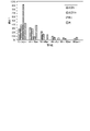
- FIG. 4 is a graph showing the opening diameter distribution obtained for the porous partition walls of the exhaust gas purifying catalysts according to Example 1 and Comparative Examples 1 to 3.
- FIG. 4 is a graph showing the distribution of powdery inorganic particles in the thickness direction obtained for the porous partition walls of the exhaust gas purifying catalyst according to Example 1.
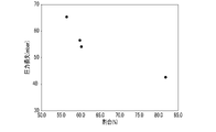
- FIG. 4 is a graph showing the relationship between the ratio S S /S and the pressure loss after PM deposition, obtained for the porous partition walls of the exhaust gas purifying catalysts according to Example 1 and Comparative Examples 1 to 3.
- FIG. 4 is a graph showing the aperture size distribution obtained for the porous partition walls of the exhaust gas purifying catalysts according to Examples 1 to 4.
- FIG. 4 is a graph showing the opening diameter distribution obtained for the porous partition walls of the exhaust gas purifying catalysts according to Examples 1 and 5 and Comparative Examples 1 and 5.
- FIG. 4 is a graph showing the aperture size distribution obtained for the porous partition walls of the exhaust gas purifying catalysts according to Examples 1 and 5 and Comparative Examples 1 and 5.
- FIG. 1 is a cross-sectional view schematically showing an exhaust gas purifying catalyst according to one embodiment of the present invention.
- FIG. 2 is a cross-sectional view showing an enlarged porous partition wall of the exhaust gas purifying catalyst shown in FIG.
- FIG. 3 is a cross-sectional view showing a further enlarged porous partition wall of the exhaust gas purifying catalyst shown in FIG.
- the white arrow has shown the flow direction of exhaust gas.
- the exhaust gas purifying catalyst 1 shown in FIGS. 1 to 3 is a particulate filter including the catalyst layer 22 shown in FIGS.
- This exhaust gas purifying catalyst 1 has a substantially cylindrical shape.
- the exhaust gas purifying catalyst 1 has a first end E1, a second end E2, a porous partition wall W, a first cell C1 and a second cell C2.
- the first end E1 and the second end E2 are the bottom surfaces of the cylinder.
- the first cell C1 extends from the first end E1 toward the second end E2.
- the first cell C1 is open at the first end E1 and closed at the second end E2.
- the second cell C2 extends from the second end E2 toward the first end E1.
- the second cell C2 is open at the second end E2 and closed at the first end E1.
- the first cell C1 and the second cell C2 are adjacent to each other with the porous partition wall W interposed therebetween.
- the first cells C1 and the second cells C2 are arranged to form a checkered pattern at the first end E1 and the second end E2.
- the exhaust gas purifying catalyst 1 includes a catalyst-coated filter 2, as shown in FIGS.
- the catalyst-coated filter 2 includes a filter substrate 21 and a catalyst layer 22, as shown in FIGS.
- the filter base material 21 includes a honeycomb structure 211 and plugs 212a and 212b, as shown in FIG.
- the honeycomb structure 211 is a cylindrical body provided with a plurality of through holes each extending from one bottom surface to the other bottom surface. One of these bottom surfaces corresponds to the first end E1 and the other bottom surface corresponds to the second end E2.
- the honeycomb structure 211 includes partition walls 211W forming side walls of these through holes. These partition walls 211W are porous and partition adjacent through holes.
- the plugs 212a block part of the holes of the honeycomb structure 211 on the second end E2 side.
- the first cell C1 is located in a space surrounded by a plug 212a closing the hole on the second end E2 side and a partition wall 211W forming a side wall of the hole.
- the plugs 212b close the remaining holes of the honeycomb structure 211 on the first end E1 side.
- the second cell C2 is located in a space surrounded by a plug 212b closing the hole on the first end E1 side and a partition wall 211W forming a side wall of the hole.
- plugs 212a and 212b are arranged such that a hole whose second end E2 side is closed with the plug 212a and a hole whose first end E1 side is closed with the plug 212b are adjacent to each other with the partition wall 211W interposed therebetween. ing.
- the first cell C1 and the second cell C2 are adjacent to each other with the partition walls 211W of the filter substrate 21 and the catalyst layer 22 provided on the pore walls thereof interposed therebetween.
- the catalyst layer 22 is supported by the filter substrate 21 as shown in FIGS. Specifically, the catalyst layer 22 is provided on the pore walls of the filter substrate 21 . That is, the catalyst layer 22 covers the inner walls of the pores of the partition walls 211W.
- the catalyst layer 22 is provided over the entire thickness of the porous partition wall W or partition wall 211W.
- a portion of the catalyst layer 22 covering the inner walls of the pores of the partition wall 211W and having a distance of a predetermined value or more from the surface of the partition wall 211W on the first cell C1 side can be omitted. That is, the entire catalyst layer 22 may be positioned on the first cell C1 side of the porous partition wall W or the partition wall 211W.
- the partition wall 211W and the portion of the catalyst layer 22 supported by the partition wall 211W constitute the filter partition wall 21W.
- the filter partition wall 21W is porous.
- the exhaust gas purifying catalyst 1 further contains inorganic particles 3, as shown in FIGS.
- the inorganic particles 3 are located on or near the surface of the porous partition wall W or the filter partition wall 21W on the first cell C1 side.
- the inorganic particles 3 are powdery. At least part of the inorganic particles 3 adhere to the catalyst-coated filter 2 , but are not fixed to the catalyst-coated filter 2 . Although the inorganic particles 3 are not fixed to each other, they can be fixed by heat treatment or chemical treatment.
- the inorganic particles 3 reduce the pore diameter of the pores located near the surface of the porous partition wall W on the first cell C1 side. In the vicinity of the surface of the porous partition wall W on the first cell C1 side, the filling rate of the inorganic particles 3 in the pores of the filter partition wall 21W tends to be low in pores with small opening diameters and high in pores with large opening diameters. be.
- the porous partition wall W has a ratio S of the total area S of pores having an opening diameter of less than 40 ⁇ m to the total area S of all pores on the surface on the first cell C1 side.
- S /S is 65% or more.
- the catalyst layer 22 is preferably configured such that the porous partition walls W have the structure described below.
- the portion of the porous partition wall W on the first cell C1 side has pores of the filter substrate 21 with a pore diameter of 5 ⁇ m or more and 10 ⁇ m in a cross section perpendicular to the surface of the porous partition wall W on the first cell C1 side.
- the ratio R F1 of the total area S C1 of the portion of the catalyst layer 22 located within the first pores, the ratio R F1 of the portion of the catalyst layer 22 located within the second pores to the total area S F2 of the second pores The ratio R F2 of the total area S C2 and the ratio R F3 of the total area S C3 of the portion of the catalyst layer 22 located within the third pores to the total area S F3 of the third pores are represented by the inequality: R F1 It is preferable to satisfy the relationship ⁇ R F2 ⁇ R F3 .
- the boundaries between continuous pores and the pore diameter of each pore are determined by a method to be described later with reference to FIG.
- the portion of the filter partition wall 21W near the surface on the first cell C1 side has a wider pore size distribution than the portion of the partition wall 211W near the surface on the first cell C1 side. Narrower, smaller average pore size.
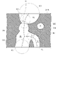
- FIG. 4 is a cross-sectional view showing a method of separating pores that are connected in a cross-sectional image of porous partition walls.
- FIG. 4 corresponds to a cross-sectional image of the porous partition wall W.
- FIG. 4 omits the catalyst layer 22 and the inorganic particles 3 to be described later.
- Step S1 In this method, first, a cross section of the porous partition wall W is imaged using a scanning electron microscope (SEM) or a transmission electron microscope (TEM).
- SEM scanning electron microscope
- TEM transmission electron microscope
- partition walls 211W (hereinafter referred to as partition walls) of the filter base material 21 are specified in the image thus acquired. Then, the space portion is specified in the partition portion.
- partition walls not only the space CV1 which is separated from both surfaces of the partition 211W but also the space CV2 which is open on at least one surface of the partition 211W is specified. A part of the catalyst layer 22 and the inorganic particles 3 may be located in the space. Then, one of these spaces is selected.
- Step S3 the area of the selected space is obtained, and the diameter of a circle having the same area as this area, that is, the equivalent circle diameter is calculated. Then, it is determined whether or not the equivalent circle diameter is 5 ⁇ m or less.
- Step S4 When this equivalent circle diameter is 5 ⁇ m or less, it is determined that the previous space corresponds to one pore, and this equivalent circle diameter is determined as the pore diameter of this pore. If there are unselected spaces, one of the unselected spaces is selected, and the process returns to step S3. If there is no unselected space, the process ends.
- the space portion CV1 when the space portion CV1 is selected, the space portion CV1 has an equivalent circle diameter of 5 ⁇ m or less, so it is determined to correspond to one pore P1. Then, this equivalent circle diameter is defined as the pore diameter of this pore P1. Then, the unselected space portion CV2 is selected, and the process returns to step S3.
- Step S5 When the equivalent circle diameter is more than 5 ⁇ m, it is determined that the above-mentioned space corresponds to two or more pores connected to each other. Then, the space portion is divided at the position where the equivalent circle diameter decreases to 50% of the equivalent circle diameter, and the boundary between a plurality of regions generated thereby is defined as the boundary of the pore.
- the space portion CV2 when the space portion CV2 is selected, the space portion CV2 has an equivalent circle diameter of more than 5 ⁇ m, so it is determined that it corresponds to two or more pores connected to each other. Then, the space portion CV2 is divided at the position where the equivalent circle diameter decreases to 50% of the equivalent circle diameter, and the boundary between a plurality of regions generated thereby is defined as the boundary of the pore.
- (Sub-step SS1) Specifically, first, a large number of circles are generated that are inscribed in the space and that are in contact with both of a pair of wall surfaces facing each other with the space interposed therebetween.
- the wall portion is a portion corresponding to the boundary between the space portion and the partition portion.
- a reference line is generated by connecting the centers of these circles. In the example shown in FIG. 4, the reference line obtained by connecting the centers of the circles is the branched dashed line CL.
- the line segment connecting the two points of contact between the first circle and the wall surface is defined as the boundary dividing the space. If the first circle is not found, the boundary that divides the space is not defined for the portion of the reference line that is on the first direction side with respect to the center of the reference circle.
- the line segment connecting the two points of contact between the second circle and the wall surface is defined as the boundary dividing the space. If the second circle is not found, the boundary that divides the space section is not defined for the portion of the reference line on the second direction side with respect to the center of the reference circle.
- the third direction the diameters of the circles with the shortest distance from the branching point to the center are confirmed. This checking is done until a circle is found whose diameter is 50% of the diameter of the reference circle.
- the third circle When such a circle (hereinafter referred to as the third circle) is found, the line segment connecting the two points of contact between the third circle and the wall surface is defined as the boundary that divides the space. If the third circle is not found, the boundary that divides the space is not determined for the portion of the reference line that is on the third direction side with respect to the branch point.
- the dashed line CL does not branch within the range corresponding to the line connecting the centers of the circles whose diameters were confirmed with the circle IC1 as the reference circle in sub-steps SS4 or SS5.
- Sub-step SS5 therefore proceeds to the next step S6 without defining an additional boundary.
- Step S6 In step S6, it is determined whether or not the boundary has been defined in step S5.
- Step S7 If no boundary is determined in step S5, it is determined that the preceding space is a single pore, and this equivalent circle diameter is determined as the pore diameter of this pore. If there are unselected spaces, one of the unselected spaces is selected, and the process returns to step S3. If there is no unselected space, the process ends.
- Step S8 If one or more boundaries are defined in step S5, one of the plurality of regions formed by dividing the above space by boundaries is determined to be one pore where the center of the reference circle is located, The circle equivalent diameter is defined as the pore diameter of this pore.
- a new space is determined by excluding the area where the center of the reference circle is located from the space. Then, this space is selected, and the process returns to step S3.
- the one where the center of the circle IC1 is located is determined to be one pore P2, and the circle equivalent diameter is determined as follows. Defined as the pore size of the pore P2. Then, a portion (hereinafter referred to as a first remainder) obtained by excluding the area corresponding to the pore P2 where the center of the circle IC1 is located from the space CV2 is defined as a new space. Then, this space is selected, and the process returns to step S3.
- the circle IC3 is specified as the reference circle in step S5. Note that the reference line need not be newly generated.
- circles IC4a and IC4b whose diameter is 50% of the diameter of circle IC3 and boundaries B1 and B2 are further specified.
- step S8 among a plurality of regions formed by dividing the first remainder by boundaries B1 and B2, the region where the center of circle IC2 is located is determined to be one pore P3. , and its equivalent circle diameter is defined as the pore diameter of the pore P3.
- a portion obtained by removing the region corresponding to the pore P3 where the center of the circle IC2 is located from the first remainder (hereinafter referred to as a second remainder) is defined as a new space. Then, this space is selected, and the process returns to step S3.
- step S4 Since the equivalent circle diameter of the second remainder is 5 ⁇ m or less, in step S4, it is determined that the second remainder corresponds to one pore P4, and this equivalent circle diameter is regarded as the pore diameter of this pore P4. stipulate. If there are unselected spaces, one of the unselected spaces is selected, and the process returns to step S3. If there is no unselected space, the process ends.
- the porous partition wall W preferably has the structure described below with reference to FIG.
- FIG. 5 is a plan view schematically showing the surface of the porous partition on the first cell side.
- FIG. 5 depicts the surface of the porous partition wall W on the side of the first cell C1.
- the pores P of the porous partition walls W are divided into first small pores with an opening diameter of less than 40 ⁇ m and first large pores with an opening diameter of 40 ⁇ m or more.
- the pores P located at the lower right and upper left are the first large pores, and the remaining pores P are the first small pores.
- the circle formed by the dashed line LL2 has an area equal to the opening of the pore P.
- the opening diameter of the pore P is the diameter of the circle formed by the dashed line LL2.
- the pores of the filter partition wall 21W are replaced with second small pores having an opening diameter of less than 40 ⁇ m. and second large pores having an opening diameter of 40 ⁇ m or more.
- the pores located at the lower right and upper left are the second large pores, and the remaining pores are the second small pores.
- the pores of the filter partition wall 21W are the regions surrounded by the solid lines LL1. Therefore, the opening diameter of the pores of the filter partition wall 21W is the diameter of a circle having the same area as the area surrounded by the solid line LL1.
- the ratio of the difference S S2 ⁇ S S1 between the total area S S2 of the second small pores and the total area S S1 of the first small pores to the total area S S2 of the second small pores (S S2 ⁇ S S1 )/S S2 is 40 % or less. Also, the ratio of the difference S L2 ⁇ S L1 between the total area S L2 of the second large pores and the total area S L1 of the first large pores to the total area S L2 of the second large pores (S L2 ⁇ S L1 )/S L2 is 60% or more.
- the second large pores have a larger degree of reduction in opening diameter due to the application of the inorganic particles 3 than the second small pores.
- Such a configuration is advantageous, for example, in reducing pores P having excessively large or excessively small opening diameters on the surface of the porous partition wall on the first cell side.
- Example 1 Manufacture of exhaust gas purifying catalyst (Example 1)
- the exhaust gas purifying catalyst described with reference to FIGS. 1 to 3 was manufactured by the following method. First, 3 parts by mass of palladium nitrate solution, 35 parts by mass of alumina powder, 32 parts by mass of ceria-containing oxide, and ion-exchanged water were mixed. This mixture was mixed with 1 part by mass of polycarboxylic acid to prepare a slurry. This slurry had a viscosity ⁇ 400 of 100 mPa ⁇ s at a temperature of 25° C. and a shear rate of 400 s ⁇ 1 .
- the filter base material was prepared.
- a columnar filter substrate with a volume of 1.3 L and a height of 114.3 mm was used.
- the slurry was supplied to one end surface (first end surface) of the filter substrate, and the gas inside the filter substrate was sucked from the other end surface (second end surface) of the filter substrate.
- This suction is performed at a temperature of 25° C. under the conditions that the linear velocity (wind speed) of the gas flow near the end of the filter substrate when the filter substrate is installed and the slurry is not supplied is 50 m/s. rice field.
- the partition walls of the filter substrate were coated with the slurry.
- the slurry was supplied to the catalyst-coated filter so that the amount of the catalyst layer with respect to the volume of the filter base material was 75 g/L.
- the slurry-coated filter substrate was then dried and fired. Thus, a catalyst-coated filter was obtained.
- inorganic particles were supplied to one surface of each filter partition wall of the catalyst-coated filter. Specifically, an aerosol containing inorganic particles as aerosol particles was supplied to the first end corresponding to the first end face of the catalyst-coated filter. At the same time, the gas inside the catalyst-coated filter was sucked from the second end corresponding to the second end face of the catalyst-coated filter. This suction was performed with the catalyst-coated filter installed with the first end facing downward.
- the amount of inorganic particles with respect to the volume of the filter substrate was 5 g/L.
- the inorganic particles sepiolite, which is a porous inorganic material and has an average particle size of 6 ⁇ m, was used. As described above, an exhaust gas purifying catalyst was obtained.
- Example 1 An exhaust gas purifying catalyst was produced in the same manner as in Example 1, except that the supply of inorganic particles to the catalyst-coated filter was omitted. That is, a catalyst-coated filter was manufactured in the same manner as in Example 1, and this was used as an exhaust gas purifying catalyst according to Comparative Example 1.
- Example 2 Exhaust gas purifying filter was prepared in the same manner as in Example 1 except that the ratio of the amount of the catalyst layer to the volume of the filter base material was changed from 75 g / L to 50 g / L and the supply of inorganic particles to the catalyst-coated filter was omitted. A catalyst was prepared.
- Exhaust gas purifying filter was prepared in the same manner as in Example 1, except that the ratio of the amount of the catalyst layer to the volume of the filter base material was changed from 75 g / L to 100 g / L, and the supply of inorganic particles to the catalyst-coated filter was omitted.
- a catalyst was prepared.
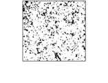
- FIG. 6 is an image obtained by binarizing a micrograph of the porous partition walls of the exhaust gas purifying catalyst according to Example 1.
- FIG. 7 is an image obtained by binarizing a microphotograph of the porous partition walls of the exhaust gas purifying catalyst according to Comparative Example 1.
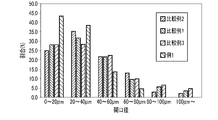
- FIG. 8 is a graph showing the opening diameter distribution obtained for the porous partition walls of the exhaust gas purifying catalysts according to Example 1 and Comparative Examples 1 to 3.
- FIG. 6 is an image obtained by binarizing a micrograph of the porous partition walls of the exhaust gas purifying catalyst according to Example 1.
- FIG. 7 is an image obtained by binarizing a microphotograph of the porous partition walls of the exhaust gas purifying catalyst according to Comparative Example 1.
- FIG. 8 is a graph showing the opening diameter distribution obtained for the porous partition walls of the exhaust gas purifying catalysts according to Example 1 and Comparative Examples 1 to 3.
- S ⁇ 20 /S is the total area of pores with an opening diameter of less than 20 ⁇ m in the total area S of all pores in the micrograph of the surface of the porous partition wall on the first cell side.
- S 20-40 /S is the ratio of the total area S 20-40 of pores having an opening diameter in the range of 20 ⁇ m or more and less than 40 ⁇ m to the total area S of all pores in the above micrograph.
- S 40-60 /S is the ratio of the total area S 40-60 of pores having an opening diameter in the range of 40 ⁇ m or more and less than 60 ⁇ m to the total area S of all pores in the above micrograph.
- S 60-80 /S is the ratio of the total area S 60-80 of pores having an opening diameter in the range of 60 ⁇ m or more and less than 80 ⁇ m to the total area S of all pores in the above micrograph.
- S 80-100 /S is the ratio of the total area S 80-100 of pores having an opening diameter in the range of 80 ⁇ m or more and less than 100 ⁇ m to the total area S of all pores in the above micrograph.
- S 100 ⁇ /S is the ratio of the total area S 100 ⁇ of pores having an opening diameter of 100 ⁇ m or more to the total area S of all pores in the micrograph.
- the sum of the total area S ⁇ 20 and S 20-40 obtained in calculating the above opening diameter is the total area of the exhaust gas purifying catalyst according to Example 1.
- SS1 the total area of the exhaust gas purifying catalyst according to Example 1.
- the sum of the total areas S 40-60 , S 60-80 , S 80-100 and S 100 ⁇ obtained when calculating the opening diameter was The total area of the exhaust gas purifying catalyst was defined as SL1 .
- the sum of the total area S ⁇ 20 and S 20-40 obtained when calculating the above opening diameter was calculated as the total area S of the exhaust gas purifying catalyst according to Comparative Example 1.
- S2 the sum of the total area S ⁇ 20 and S 20-40 obtained in calculating the above opening diameter
- the ratio (S L2 ⁇ S L1 )/S L2 was larger than the ratio (S S2 ⁇ S S1 )/S S2 . That is, in the exhaust gas purifying catalyst according to Example 1, among the pores opened on the surface of the porous partition wall on the first cell side, those with a large opening diameter are compared to those with a small opening diameter. The filling rate was high.
- the inorganic particle distribution in the thickness direction of the porous partition walls was measured. Specifically, regarding the exhaust gas purifying catalyst according to Example 1, the cross section of the porous partition wall was imaged with a scanning electron microscope to obtain a grayscale image. This imaging was performed on a cross section of a portion of the porous partition wall where the distance from the first end and the distance from the second end were equal. Next, the position analyzed by the energy dispersive X-ray spectrometer was specified in the grayscale image, and the intensity of characteristic X-rays derived from calcium was measured. Here, line analysis was performed along the thickness direction of the porous partition walls.
- a composite image was generated by superimposing colored points having brightness (gradation value) corresponding to the intensity of the characteristic X-ray on the grayscale image. From this composite image, the relationship between the distance from the surface of the catalyst-coated filter on the first cell side and the gradation value was determined.
- FIG. 9 is a graph showing the distribution of powdery inorganic particles in the thickness direction obtained for the porous partition walls of the exhaust gas purifying catalyst according to Example 1.
- the horizontal axis represents the distance from the surface of the catalyst-coated filter on the side of the first cell, and the vertical axis represents the gradation value.
- the inorganic particles were unevenly distributed on the first cell side of the porous partition wall.
- the amounts A, A1 and A2 described above satisfy the relationship represented by the inequality (A1+A2)/A ⁇ 90%. Specifically, the ratio (A1+A2)/A was 98.7%.
- the horizontal axis represents the ratio S S /S
- the vertical axis represents the pressure loss.
- the ratio S S /S is the sum of the above ratios S ⁇ 20 /S and S 20-40 /S.
- the ratio S M+L /S is the sum of the above ratios S 40-60 , S 60-80 , S 80-100 and S 100 ⁇ .
- the exhaust gas purifying catalyst according to Example 1 has a larger ratio S S /S than the exhaust gas purifying catalysts according to Comparative Examples 1 to 3, and the pressure loss after PM deposition was small.
- Example 2 Manufacture of exhaust gas purifying catalyst (Example 2) An exhaust gas purifying catalyst was produced in the same manner as in Example 1, except that the ratio of the amount of the catalyst layer to the volume of the filter base material was changed from 75 g/L to 50 g/L.
- Example 3 An exhaust gas purifying catalyst was produced in the same manner as in Example 1, except that the ratio of the amount of the catalyst layer to the volume of the filter base material was changed from 75 g/L to 100 g/L.
- Example 4 An exhaust gas purifying catalyst was produced in the same manner as in Example 1, except that the ratio of the amount of the catalyst layer to the volume of the filter base material was changed from 75 g/L to 125 g/L.
- Example 5 An exhaust gas purifying catalyst was produced in the same manner as in Example 1, except that the amount of inorganic particles relative to the volume of the filter base material was changed from 5 g/L to 20 g/L.
- Example 4 An exhaust gas purifying catalyst was produced in the same manner as in Example 1, except that the amount of inorganic particles relative to the volume of the filter base material was changed from 5 g/L to 1 g/L.
- the ratio of pores with large opening diameters on the surface of the porous partition wall on the first cell side by producing the exhaust gas purifying catalyst by the above method could be made smaller.
- the total area S of all pores decreased.
- the total area S of all pores obtained for the exhaust gas purifying catalysts according to Examples 2, 3 and 4 is the total area S of all pores obtained for the exhaust gas purifying catalyst according to Example 1. It was more than 1.3 times, more than 0.7 times, and less than 0.4 times that of S.
- the filling rates R F1 , R F2 and R F3 satisfy the relationship represented by the inequality: R F1 ⁇ R F2 ⁇ R F3 .
- the rate R F1 was in the range 10-40%
- the filling rate R F2 was in the range 15-40%
- the filling rate R F3 was in the range 20-45%.
Landscapes
- Chemical & Material Sciences (AREA)
- Engineering & Computer Science (AREA)
- Chemical Kinetics & Catalysis (AREA)
- Materials Engineering (AREA)
- Organic Chemistry (AREA)
- Combustion & Propulsion (AREA)
- Health & Medical Sciences (AREA)
- General Engineering & Computer Science (AREA)
- Mechanical Engineering (AREA)
- General Chemical & Material Sciences (AREA)
- Analytical Chemistry (AREA)
- Oil, Petroleum & Natural Gas (AREA)
- Toxicology (AREA)
- Environmental & Geological Engineering (AREA)
- Biomedical Technology (AREA)
- Catalysts (AREA)
- Exhaust Gas Treatment By Means Of Catalyst (AREA)
- Exhaust Gas After Treatment (AREA)
- Processes For Solid Components From Exhaust (AREA)
- Crystallography & Structural Chemistry (AREA)
Abstract
Description
先ず、多孔質隔壁の第1セル側の表面を、200倍の倍率で撮像して、グレイスケール画像を取得する。この撮像には、光学顕微鏡を使用する。また、この撮像は、多孔質隔壁の第1セル側の表面のうち、触媒塗布フィルタの長さ方向における中央付近の領域に対して行う。なお、この「長さ方向」は、第1及び第2セルの長さ方向と等しい。次いで、得られたグレイスケール画像を二値化して、二値化画像を取得する。そして、二値化画像における第1セル側表面の黒色部の各々の面積を求め、この面積と等しい面積を有する円の直径、即ち円相当径を、その黒色部に対応した細孔の「開口径」とする。ここでは、或る黒色部が他の黒色部から離間している限り、それがどのような形状を有していようと、その黒色部は1つの細孔に対応しているとする。なお、この画像処理には、画像処理ソフトウェア「ImageJ」を使用することができる。
触媒層の原料は、触媒金属と、任意に、多孔質担体及び助触媒の少なくとも一方とを含んでいる。触媒金属は、例えば、分散媒に溶解可能な金属化合物の形態で、又は、触媒金属を多孔質担体に担持させてなる担持触媒の形態でスラリーに含まれ得る。分散媒は、例えば、水などの水系溶媒である。
以上のようにして、上記態様の何れかに係る排ガス浄化用触媒、特には粉末付加触媒塗布フィルタが得られる。
この方法では、先ず、走査電子顕微鏡(SEM)又は透過電子顕微鏡(TEM)を用いて、多孔質隔壁Wの断面を撮像する。この断面は、多孔質隔壁Wの第1セルC1側の表面に垂直な断面、即ち、多孔質隔壁Wの厚さ方向に平行な断面である。
次に、このようにして取得した画像において、フィルタ基材21の隔壁211W(以下、隔壁部という)を特定する。そして、隔壁部において、空間部を特定する。ここでは、空間部CV1のように隔壁211Wの双方の表面から離間したものだけでなく、空間部CV2のように、隔壁211Wの少なくとも一方の表面で開口したものについても特定する。空間部内には、触媒層22や無機粒子3の一部が位置していてもよい。そして、これら空間部から1つを選択する。
次に、選択した空間部の面積を求め、この面積と同一の面積を有する円の直径、即ち、円相当径を算出する。そして、円相当径が5μm以下であるか否かを判断する。
この円相当径が5μm以下である場合は、先の空間部は1つの細孔に相当すると判断し、この円相当径をこの細孔の細孔径であると定める。そして、選択していない空間部がある場合は、未選択の空間部の1つを選択し、ステップS3へ戻る。選択していない空間部がない場合は、処理を終了する。
円相当径が5μm超である場合、上記の空間部は、2以上の細孔が連結したものに相当すると判断する。そして、この円相当径の50%まで円相当径が減少する位置で空間部を区分し、それによって生じた複数の領域間の境界を細孔の境界として定める。
具体的には、先ず、空間部に内接し且つ空間部を間に挟んで向き合った一対の壁面部の双方と接した多数の円を生成する。ここで、壁面部は、空間部と隔壁部との境界に相当する部分である。ここでは、隔壁211Wの一対の主面間に中心が位置した円のみを生成する。そして、これら円の中心を結ぶことにより、基準線を生成する。図4に示す例では、円の中心を結ぶことにより得られる基準線は、分岐した破線CLである。
次に、上記の円のうち、直径が最大の円を特定する(以下、基準円という)。図4の例では、円IC1を特定する。
続いて、基準円の中心から基準線に沿って中心が一方向(以下、第1方向という)に並んだ円について、基準円との中心間距離が短い円から順に直径を確認する。この確認は、直径が基準円の直径の50%である円が見出されるまで行う。
次いで、基準円の中心から基準線に沿って中心が逆方向(以下、第2方向という)に並んだ円について、基準円との中心間距離が短い円から順に直径を確認する。この確認は、直径が基準円の直径の50%である円が見出されるまで行う。
基準線が、サブステップSS4又はSS5において直径を確認した円の中心を結ぶ線に相当する部分の範囲内で分岐しているか判断する。
ステップS6では、ステップS5において境界が定められたか否かを判断する。
ステップS5において境界が1つも定められなかった場合には、先の空間部は1つの細孔であると判断し、この円相当径をこの細孔の細孔径であると定める。そして、選択していない空間部がある場合は、未選択の空間部の1つを選択し、ステップS3へ戻る。選択していない空間部がない場合は、処理を終了する。
ステップS5において1以上の境界が定められた場合、先の空間部を境界によって区分してなる複数の領域のうち、基準円の中心が位置したものを、1つの細孔であると判断し、その円相当径を、この細孔の細孔径であると定める。
図5は、多孔質隔壁の第1セル側の表面を概略的に示す平面図である。図5には、多孔質隔壁Wの第1セルC1側の表面を描いている。
(例1)
図1乃至図3を用いて説明した排ガス浄化用触媒を、以下の方法により製造した。
先ず、3質量部の硝酸パラジウム溶液と35質量部のアルミナ粉末と32質量部のセリア含有酸化物とイオン交換水とを混合した。この混合液に、1質量部のポリカルボン酸を混合して、スラリーを調製した。このスラリーは、温度が25℃及びせん断速度が400s-1における粘度η400が100mPa・sであった。
このようにして、触媒塗布フィルタを得た。
以上のようにして、排ガス浄化用触媒を得た。
触媒塗布フィルタへの無機粒子の供給を省略したこと以外は例1と同様の方法により、排ガス浄化用触媒を製造した。即ち、例1と同様の方法により触媒塗布フィルタを製造し、これを比較例1に係る排ガス浄化用触媒とした。
フィルタ基材の容積に対する触媒層の量の比を75g/Lから50g/Lへ変更し、触媒塗布フィルタへの無機粒子の供給を省略したこと以外は例1と同様の方法により、排ガス浄化用触媒を製造した。
フィルタ基材の容積に対する触媒層の量の比を75g/Lから100g/Lへ変更し、触媒塗布フィルタへの無機粒子の供給を省略したこと以外は例1と同様の方法により、排ガス浄化用触媒を製造した。
例1及び比較例1乃至3に係る排ガス浄化用触媒の各々について、上述した方法により、多孔質隔壁の第1セル側の表面における開口径を測定した。結果を、図6乃至図8及び表1に示す。
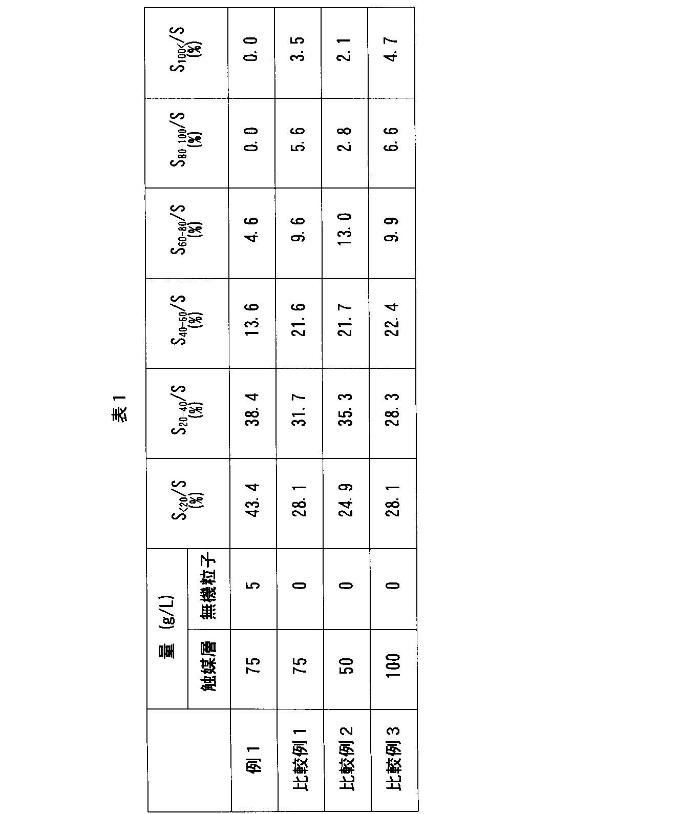
例1に係る排ガス浄化用触媒について、上述した比(SS2-SS1)/SS2及び比(SL2-SL1)/SL2を算出した。
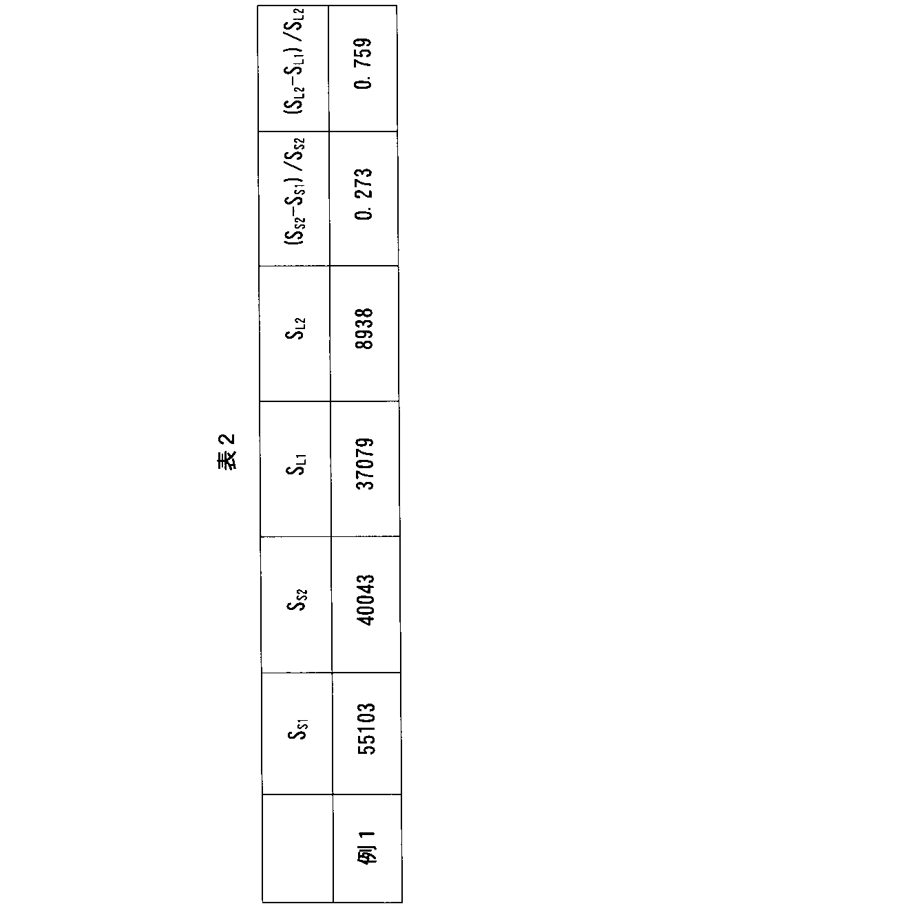
例1に係る排ガス浄化用触媒について、多孔質隔壁の厚さ方向における無機粒子分布を測定した。具体的には、例1に係る排ガス浄化用触媒について、その多孔質隔壁の断面を、走査電子顕微鏡で撮像して、グレイスケール画像を取得した。この撮像は、多孔質隔壁のうち、第1端からの距離と第2端からの距離とが等しい部分の断面に対して行った。次いで、エネルギー分散型X線分析装置による分析位置を先のグレイスケール画像において指定して、カルシウムに由来する特性X線の強度を測定した。ここでは、多孔質隔壁の厚さ方向に沿った線分析を行った。そして、先のグレイスケール画像に、特性X線の強度に応じた明るさ(濃淡値)を有し且つ着色した点を重ね合わせてなる合成画像を生成した。この合成画像から、触媒塗布フィルタの第1セル側の面からの距離と濃淡値との関係を求めた。
例1及び比較例1乃至3に係る排ガス浄化用触媒体の各々について、圧力損失の評価を行った。具体的には、煤発生器で軽油を燃焼させてPMを発生させ、これら排ガス浄化用触媒体の各々にPMを蓄積させた。PMの蓄積量が1g/Lに達した時点で、排ガス浄化用触媒の各々に対して圧力損失の測定を行った。圧力損失は、ガス温度を240℃、ガス流量を250kg/時間として測定した。結果を表3及び図10に示す。

(例2)
フィルタ基材の容積に対する触媒層の量の比を75g/Lから50g/Lへ変更したこと以外は例1と同様の方法により、排ガス浄化用触媒を製造した。
フィルタ基材の容積に対する触媒層の量の比を75g/Lから100g/Lへ変更したこと以外は例1と同様の方法により、排ガス浄化用触媒を製造した。
フィルタ基材の容積に対する触媒層の量の比を75g/Lから125g/Lへ変更したこと以外は例1と同様の方法により、排ガス浄化用触媒を製造した。
フィルタ基材の容積に対する無機粒子の量を5g/Lから20g/Lへ変更したこと以外は例1と同様の方法により、排ガス浄化用触媒を製造した。
フィルタ基材の容積に対する無機粒子の量を5g/Lから1g/Lへ変更したこと以外は例1と同様の方法により、排ガス浄化用触媒を製造した。
例2乃至4に係る排ガス浄化用触媒について、上記と同様の方法により、多孔質隔壁の第1セル側の表面における開口径を測定した。結果を、表4及び図11に示す。
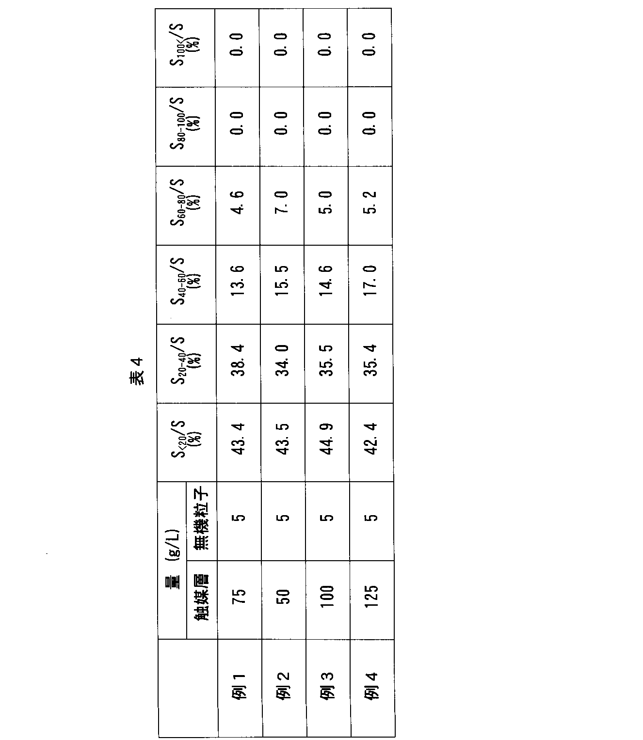
例5及び比較例4に係る排ガス浄化用触媒について、上記と同様の方法により、多孔質隔壁の第1セル側の表面における開口径を測定した。結果を、表5及び図12に示す。
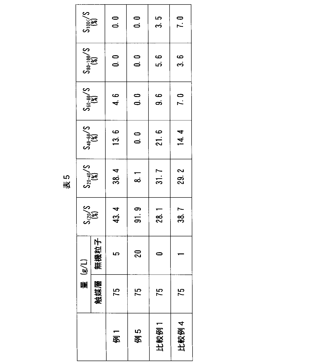
例1乃至5及び比較例1乃至4に係る排ガス浄化用触媒について、図4を参照しながら説明した方法により、充填率RF1、RF2及びRF3を求めた。一例として、例3に係る排ガス浄化用触媒について得られた結果を、以下の表6に示す。

Claims (15)
- 触媒塗布フィルタを備え、前記触媒塗布フィルタは、フィルタ基材と前記フィルタ基材の細孔壁上に設けられた触媒層とを含んだ排ガス浄化用触媒であって、
第1端と第2端と多孔質隔壁と第1セルと第2セルとを有し、前記第1セルは、前記第1端から前記第2端へ向けて伸び、前記第1端で開口し、前記第2端で閉塞され、前記第2セルは、前記第2端から前記第1端へ向けて伸び、前記第2端で開口し、前記第1端で閉塞され、前記第1セル及び前記第2セルは前記多孔質隔壁を間に挟んで隣接し、
前記多孔質隔壁は、前記第1セル側の表面において、全細孔の合計面積Sに占める、開口径が40μm未満である細孔の合計面積SSの割合SS/Sが65%以上である排ガス浄化用触媒。 - 前記多孔質隔壁は、前記表面における、前記全細孔の前記合計面積Sに占める、開口径が40μm以上60μm未満である細孔の合計面積SMの割合SM/Sが30%以下である請求項1に記載の排ガス浄化用触媒。
- 前記多孔質隔壁は、前記表面における、前記全細孔の前記合計面積Sに占める、開口径が60μm以上である細孔の合計面積SLの割合SL/Sが15%以下である請求項1又は2に記載の排ガス浄化用触媒。
- 前記多孔質隔壁は、前記表面における、前記全細孔の前記合計面積Sに占める、開口径が20μm未満である細孔の合計面積SSSの割合SSS/Sが50%以下である請求項1乃至3の何れか1項に記載の排ガス浄化用触媒。
- 前記多孔質隔壁のうち前記第1セル側の部分は、前記表面に垂直な断面において、前記フィルタ基材の細孔を、細孔径が5μm以上10μm未満の第1細孔と、細孔径が10μm以上20μm未満の第2細孔と、細孔径が20μm以上の第3細孔とに区分した場合に、前記第1細孔の前記触媒層による充填率RF1、前記第2細孔の前記触媒層による充填率RF2、及び前記第3細孔の前記触媒層による充填率RF3は、不等式:RF1<RF2<RF3に示す関係を満たす請求項1乃至4の何れか1項に記載の排ガス浄化用触媒。
- 前記充填率RF1は40%以下であり、前記充填率RF2は40%以下であり、前記充填率RF3は45%以下である請求項5に記載の排ガス浄化用触媒。
- 前記充填率RF3は20%以上である請求項5又は6に記載の排ガス浄化用触媒。
- 前記フィルタ基材の容積に対する前記触媒層の質量の比は、10乃至300g/Lの範囲内にある請求項1乃至7の何れか1項に記載の排ガス浄化用触媒。
- 前記触媒塗布フィルタによって支持された粉末状の無機粒子を更に備えた請求項1乃至8の何れか1項に記載の排ガス浄化用触媒。
- 前記無機粒子は、前記多孔質隔壁の前記第1セル側に偏在した請求項9に記載の排ガス浄化用触媒。
- 前記無機粒子の全量Aと、前記触媒塗布フィルタの前記第1セル側の面上に位置した前記無機粒子の量A1と、前記触媒塗布フィルタの細孔内であって、前記触媒塗布フィルタの前記第1セル側の前記面からの距離が、前記触媒塗布フィルタのうち前記多孔質隔壁に対応した部分の厚さの20%以下である前記無機粒子の量A2とは、不等式(A1+A2)/A≧90%で表される関係を満たす請求項9に記載の排ガス浄化用触媒。
- 前記表面において、前記多孔質隔壁の前記細孔を、開口径が40μm未満の第1小細孔と、開口径が40μm以上の第1大細孔とに区分し、前記触媒塗布フィルタのうち前記多孔質隔壁に対応した部分の前記第1セル側の表面において、前記部分が有する細孔を、開口径が40μm未満の第2小細孔と、開口径が40μm以上の第2大細孔とに区分した場合に、前記第2小細孔の合計面積SS2に対する、前記合計面積SS2と前記第1小細孔の合計面積SS1との差SS2-SS1の比(SS2-SS1)/SS2は40%以下であり、前記第2大細孔の合計面積SL2に対する、前記合計面積SL2と前記第1大細孔の合計面積SL1との差SL2-SL1の比(SL2-SL1)/SL2は60%以上である請求項9乃至11の何れか1項に記載の排ガス浄化用触媒。
- 前記無機粒子は1乃至50μmの範囲内の平均粒子径を有する請求項9乃至12の何れか1項に記載の排ガス浄化用触媒。
- 前記無機粒子は、金属酸化物、金属水酸化物、金属炭酸塩、金属リン酸塩、金属硝酸塩、金属硫酸塩、及び粘土鉱物からなる群より選択される1以上を含んだ請求項9乃至13の何れか1項に記載の排ガス浄化用触媒。
- 前記フィルタ基材の容積に対する前記無機粒子の質量の比は、3乃至50g/Lの範囲内にある請求項9乃至14の何れか1項に記載の排ガス浄化用触媒。
Priority Applications (3)
| Application Number | Priority Date | Filing Date | Title |
|---|---|---|---|
| CN202280015005.4A CN116917041B (zh) | 2021-02-16 | 2022-01-25 | 废气净化用催化剂 |
| EP22755852.5A EP4295947A4 (en) | 2021-02-16 | 2022-01-25 | EXHAUST GAS CONTROL CATALYST |
| US18/352,116 US20230364589A1 (en) | 2021-02-16 | 2023-07-13 | Exhaust gas-purifying catalyst |
Applications Claiming Priority (2)
| Application Number | Priority Date | Filing Date | Title |
|---|---|---|---|
| JP2021-022649 | 2021-02-16 | ||
| JP2021022649A JP7717467B2 (ja) | 2021-02-16 | 2021-02-16 | 排ガス浄化用触媒 |
Related Child Applications (1)
| Application Number | Title | Priority Date | Filing Date |
|---|---|---|---|
| US18/352,116 Continuation US20230364589A1 (en) | 2021-02-16 | 2023-07-13 | Exhaust gas-purifying catalyst |
Publications (1)
| Publication Number | Publication Date |
|---|---|
| WO2022176528A1 true WO2022176528A1 (ja) | 2022-08-25 |
Family
ID=82931559
Family Applications (1)
| Application Number | Title | Priority Date | Filing Date |
|---|---|---|---|
| PCT/JP2022/002681 Ceased WO2022176528A1 (ja) | 2021-02-16 | 2022-01-25 | 排ガス浄化用触媒 |
Country Status (5)
| Country | Link |
|---|---|
| US (1) | US20230364589A1 (ja) |
| EP (1) | EP4295947A4 (ja) |
| JP (1) | JP7717467B2 (ja) |
| CN (1) | CN116917041B (ja) |
| WO (1) | WO2022176528A1 (ja) |
Families Citing this family (2)
| Publication number | Priority date | Publication date | Assignee | Title |
|---|---|---|---|---|
| JP7717468B2 (ja) * | 2021-02-16 | 2025-08-04 | 株式会社キャタラー | 排ガス浄化用触媒 |
| EP4335547A1 (en) * | 2022-09-12 | 2024-03-13 | Johnson Matthey Public Limited Company | Method of forming an inorganic oxide coating on a monolith article |
Citations (6)
| Publication number | Priority date | Publication date | Assignee | Title |
|---|---|---|---|---|
| JP2004076717A (ja) * | 2002-06-17 | 2004-03-11 | Toyota Motor Corp | 排ガス浄化フィルタと排ガス浄化用触媒及びその製造方法 |
| WO2010110011A1 (ja) * | 2009-03-26 | 2010-09-30 | 日本碍子株式会社 | ハニカムフィルタ及びハニカムフィルタの製造方法 |
| WO2019197177A1 (de) | 2018-04-09 | 2019-10-17 | Umicore Ag & Co. Kg | Beschichteter wandflussfilter |
| WO2020031975A1 (ja) * | 2018-08-09 | 2020-02-13 | エヌ・イーケムキャット株式会社 | 触媒塗工ガソリンパティキュレートフィルター及びその製造方法 |
| WO2020100582A1 (ja) * | 2018-11-15 | 2020-05-22 | 株式会社キャタラー | パティキュレートフィルタ |
| JP2020165396A (ja) * | 2019-03-29 | 2020-10-08 | 株式会社Soken | 排ガス浄化フィルタ |
Family Cites Families (6)
| Publication number | Priority date | Publication date | Assignee | Title |
|---|---|---|---|---|
| JP2001239113A (ja) * | 2000-03-01 | 2001-09-04 | Mitsubishi Paper Mills Ltd | 空気清浄化フィルター |
| JP3874270B2 (ja) * | 2002-09-13 | 2007-01-31 | トヨタ自動車株式会社 | 排ガス浄化フィルタ触媒及びその製造方法 |
| JP2010269205A (ja) * | 2009-05-19 | 2010-12-02 | Toyota Motor Corp | 排ガス浄化用触媒 |
| GB201100595D0 (en) * | 2010-06-02 | 2011-03-02 | Johnson Matthey Plc | Filtration improvements |
| US10981113B2 (en) * | 2017-09-21 | 2021-04-20 | Cataler Corporation | Exhaust gas purification catalyst body |
| JP7211709B2 (ja) * | 2018-02-27 | 2023-01-24 | エヌ・イーケムキャット株式会社 | 排ガス浄化用三元触媒及びその製造方法、並びに一体構造型排ガス浄化用触媒 |
-
2021
- 2021-02-16 JP JP2021022649A patent/JP7717467B2/ja active Active
-
2022
- 2022-01-25 WO PCT/JP2022/002681 patent/WO2022176528A1/ja not_active Ceased
- 2022-01-25 CN CN202280015005.4A patent/CN116917041B/zh active Active
- 2022-01-25 EP EP22755852.5A patent/EP4295947A4/en active Pending
-
2023
- 2023-07-13 US US18/352,116 patent/US20230364589A1/en active Pending
Patent Citations (6)
| Publication number | Priority date | Publication date | Assignee | Title |
|---|---|---|---|---|
| JP2004076717A (ja) * | 2002-06-17 | 2004-03-11 | Toyota Motor Corp | 排ガス浄化フィルタと排ガス浄化用触媒及びその製造方法 |
| WO2010110011A1 (ja) * | 2009-03-26 | 2010-09-30 | 日本碍子株式会社 | ハニカムフィルタ及びハニカムフィルタの製造方法 |
| WO2019197177A1 (de) | 2018-04-09 | 2019-10-17 | Umicore Ag & Co. Kg | Beschichteter wandflussfilter |
| WO2020031975A1 (ja) * | 2018-08-09 | 2020-02-13 | エヌ・イーケムキャット株式会社 | 触媒塗工ガソリンパティキュレートフィルター及びその製造方法 |
| WO2020100582A1 (ja) * | 2018-11-15 | 2020-05-22 | 株式会社キャタラー | パティキュレートフィルタ |
| JP2020165396A (ja) * | 2019-03-29 | 2020-10-08 | 株式会社Soken | 排ガス浄化フィルタ |
Non-Patent Citations (1)
| Title |
|---|
| See also references of EP4295947A4 |
Also Published As
| Publication number | Publication date |
|---|---|
| JP7717467B2 (ja) | 2025-08-04 |
| JP2022124800A (ja) | 2022-08-26 |
| CN116917041B (zh) | 2025-12-19 |
| EP4295947A1 (en) | 2023-12-27 |
| CN116917041A (zh) | 2023-10-20 |
| US20230364589A1 (en) | 2023-11-16 |
| EP4295947A4 (en) | 2024-12-25 |
Similar Documents
| Publication | Publication Date | Title |
|---|---|---|
| RU2752392C1 (ru) | Бензиновый фильтр частиц | |
| JP4355506B2 (ja) | 触媒担持フィルタ及びこれを用いた排ガス浄化システム | |
| JP6297767B2 (ja) | 排ガス浄化装置 | |
| US7517830B2 (en) | Substrate for exhaust-gas purifying filter catalyst | |
| JP7065551B2 (ja) | 触媒塗工ガソリンパティキュレートフィルター及びその製造方法 | |
| JPWO2012046484A1 (ja) | 排ガス浄化装置 | |
| CN113039015A (zh) | 微粒过滤器 | |
| JPWO2019058948A1 (ja) | 排ガス浄化用触媒体 | |
| US20230364589A1 (en) | Exhaust gas-purifying catalyst | |
| JP6940786B2 (ja) | 排ガス浄化フィルタ | |
| CN112203764B (zh) | 废气净化催化剂的制造方法 | |
| CN112218719B (zh) | 废气净化催化剂 | |
| JP7446376B1 (ja) | パティキュレートフィルタ | |
| WO2022176529A1 (ja) | 排ガス浄化用触媒 | |
| JP7271610B2 (ja) | パティキュレートフィルタ | |
| CN112218718B (zh) | 废气净化催化剂 | |
| WO2021131630A1 (ja) | 排ガス浄化用触媒 | |
| JP2021171676A (ja) | 排ガス浄化装置 | |
| WO2022269947A1 (ja) | パティキュレートフィルタ | |
| JP2004108197A (ja) | ハニカムフィルター |
Legal Events
| Date | Code | Title | Description |
|---|---|---|---|
| 121 | Ep: the epo has been informed by wipo that ep was designated in this application |
Ref document number: 22755852 Country of ref document: EP Kind code of ref document: A1 |
|
| WWE | Wipo information: entry into national phase |
Ref document number: 202317054659 Country of ref document: IN |
|
| WWE | Wipo information: entry into national phase |
Ref document number: 202280015005.4 Country of ref document: CN |
|
| WWE | Wipo information: entry into national phase |
Ref document number: 2022755852 Country of ref document: EP |
|
| NENP | Non-entry into the national phase |
Ref country code: DE |
|
| ENP | Entry into the national phase |
Ref document number: 2022755852 Country of ref document: EP Effective date: 20230918 |