WO2022176719A1 - 画像処理装置、画像処理方法及びプログラム - Google Patents
画像処理装置、画像処理方法及びプログラム Download PDFInfo
- Publication number
- WO2022176719A1 WO2022176719A1 PCT/JP2022/004991 JP2022004991W WO2022176719A1 WO 2022176719 A1 WO2022176719 A1 WO 2022176719A1 JP 2022004991 W JP2022004991 W JP 2022004991W WO 2022176719 A1 WO2022176719 A1 WO 2022176719A1
- Authority
- WO
- WIPO (PCT)
- Prior art keywords
- virtual viewpoint
- information
- color
- image
- image processing
- Prior art date
- Legal status (The legal status is an assumption and is not a legal conclusion. Google has not performed a legal analysis and makes no representation as to the accuracy of the status listed.)
- Ceased
Links
Images


Classifications
-
- G—PHYSICS
- G06—COMPUTING OR CALCULATING; COUNTING
- G06T—IMAGE DATA PROCESSING OR GENERATION, IN GENERAL
- G06T15/00—Three-dimensional [3D] image rendering
- G06T15/10—Geometric effects
- G06T15/20—Perspective computation
-
- H—ELECTRICITY
- H04—ELECTRIC COMMUNICATION TECHNIQUE
- H04N—PICTORIAL COMMUNICATION, e.g. TELEVISION
- H04N13/00—Stereoscopic video systems; Multi-view video systems; Details thereof
- H04N13/20—Image signal generators
- H04N13/275—Image signal generators from three-dimensional [3D] object models, e.g. computer-generated stereoscopic image signals
- H04N13/279—Image signal generators from three-dimensional [3D] object models, e.g. computer-generated stereoscopic image signals the virtual viewpoint locations being selected by the viewers or determined by tracking
-
- G—PHYSICS
- G06—COMPUTING OR CALCULATING; COUNTING
- G06T—IMAGE DATA PROCESSING OR GENERATION, IN GENERAL
- G06T7/00—Image analysis
- G06T7/50—Depth or shape recovery
-
- G—PHYSICS
- G06—COMPUTING OR CALCULATING; COUNTING
- G06T—IMAGE DATA PROCESSING OR GENERATION, IN GENERAL
- G06T7/00—Image analysis
- G06T7/90—Determination of colour characteristics
-
- H—ELECTRICITY
- H04—ELECTRIC COMMUNICATION TECHNIQUE
- H04N—PICTORIAL COMMUNICATION, e.g. TELEVISION
- H04N13/00—Stereoscopic video systems; Multi-view video systems; Details thereof
- H04N13/30—Image reproducers
- H04N13/366—Image reproducers using viewer tracking
- H04N13/383—Image reproducers using viewer tracking for tracking with gaze detection, i.e. detecting the lines of sight of the viewer's eyes
-
- H—ELECTRICITY
- H04—ELECTRIC COMMUNICATION TECHNIQUE
- H04N—PICTORIAL COMMUNICATION, e.g. TELEVISION
- H04N23/00—Cameras or camera modules comprising electronic image sensors; Control thereof
- H04N23/60—Control of cameras or camera modules
-
- G—PHYSICS
- G06—COMPUTING OR CALCULATING; COUNTING
- G06T—IMAGE DATA PROCESSING OR GENERATION, IN GENERAL
- G06T2207/00—Indexing scheme for image analysis or image enhancement
- G06T2207/10—Image acquisition modality
- G06T2207/10024—Color image
Definitions
- the present disclosure relates to an image processing device that generates virtual viewpoint images.
- Patent Document 1 discloses determining the color of an object in a virtual viewpoint image using a plurality of images acquired by a physical camera specified according to the line-of-sight direction of the virtual camera.
- an object of the present disclosure is to appropriately determine the color of an object included in a virtual viewpoint image.
- the image processing apparatus of the present disclosure includes acquisition means for acquiring virtual viewpoint information for specifying a position of a virtual viewpoint and a line-of-sight direction from the virtual viewpoint; a first method for determining a color based on shape information for specifying the three-dimensional shape of said object and images acquired by a plurality of imaging devices; one of the second methods of determining a color based on shape information and color information specifying a color corresponding to a component of the shape information, the color information not changing depending on the line-of-sight direction from the virtual viewpoint; and a virtual viewpoint including an object whose color is determined based on the method selected by the selecting means, and showing the appearance from the virtual viewpoint specified by the virtual viewpoint information acquired by the acquiring means. and generating means for generating an image.
- FIG. 4 is a diagram showing an example of a virtual viewpoint image for each terminal according to the first embodiment;
- FIG. 4 is a flow chart showing an example of an image processing method for generating a virtual viewpoint image according to the first embodiment;
- 7 is a flowchart showing an example of processing for generating determination information according to the first embodiment;
- FIG. 11 is a diagram showing an example of a virtual viewpoint image according to Embodiment 2;
- 10 is a flowchart showing an example of processing for generating determination information according to the second embodiment;
- FIG. 12 is a diagram showing an example of a virtual viewpoint image according to Embodiment 3;
- FIG. 12 is a flowchart showing an example of processing for generating determination information according to the third embodiment;
- FIG. It is a figure which shows an example of shape information.
- a virtual viewpoint image is an image generated by freely manipulating the position and orientation of a virtual camera by a user and/or a dedicated operator, and is also called a free viewpoint image or an arbitrary viewpoint image.
- the virtual viewpoint is specified by user operation will be mainly described, but the virtual viewpoint may be specified automatically based on the result of image analysis or the like.
- image is assumed to include the concepts of both moving images and still images.
- a virtual camera is a virtual camera different from a plurality of imaging devices actually installed around an imaging area, and is a concept for conveniently explaining a virtual viewpoint related to generation of a virtual viewpoint image.
- the virtual viewpoint image can be regarded as an image captured from a virtual viewpoint set within the virtual space associated with the imaging region.
- the position and orientation of the viewpoint in the virtual imaging can be expressed as the position and orientation of the virtual camera.
- the virtual viewpoint image is an image simulating the captured image obtained by the camera when it is assumed that the camera exists at the position of the virtual viewpoint set in the space.
- the content of temporal transition of the virtual viewpoint is referred to as a virtual camera path.
- the imaging device only needs to have a physical camera.
- the imaging device may have a function of performing various image processing in addition to the physical camera.
- the imaging device may have a processing unit that performs foreground/background separation processing.
- the imaging device may have a control unit that performs transmission control for transmitting an image of a part of the captured image.
- the imaging device may have a plurality of physical cameras.
- FIG. 1A is a diagram showing an example of the overall configuration of an image processing system according to this embodiment.
- the image processing system 1 is a system that generates a virtual viewpoint image representing a view from a designated virtual viewpoint based on a plurality of images captured by a plurality of imaging devices and a designated virtual viewpoint.
- the image processing system 1 acquires processing performance information indicating the computing performance and data transfer speed of the user terminal, and determines a rendering method according to the processing performance information. Then, the image processing system 1 generates and outputs a virtual viewpoint image based on the determined rendering method.
- the image processing system 1 has an imaging system 10 , a first image processing device 20 , a database 30 , a second image processing device 40 , an input device 50 and a display device 60 .
- the imaging system 10 has multiple physical cameras.
- a plurality of physical cameras are placed at different positions to synchronously photograph the object from different viewpoints. Synchronization refers to a state in which imaging timings are controlled to be substantially the same.
- a plurality of captured images and external/internal parameters for each physical camera of the imaging system 10 are transmitted to the first image processing device 20 .
- the extrinsic parameters of the camera are parameters (for example, rotation matrix, position vector, etc.) that indicate the position and orientation of the camera.
- Camera intrinsic parameters are camera-specific intrinsic parameters, such as focal length, image center, and lens distortion parameters. Note that a plurality of physical cameras may be arranged so as to surround an object and capture images of the object.
- Each of the plurality of physical cameras may be connected to the first image processing device with a cable.
- a plurality of physical cameras may be connected in cascade, and may also be connected in cascade with the first image processing device.
- the plurality of physical cameras may all be physical cameras with the same focal length.
- the plurality of physical cameras may include a physical camera having a telephoto lens and a physical camera having a wide-angle lens. may include a physical camera set to
- the first image processing device 20 generates shape information of the foreground object based on a plurality of images input from the imaging system 10 and external/internal parameters for each physical camera, and outputs the shape information to the database 30 .
- This shape information is three-dimensional shape data representing the three-dimensional shape of the object.
- a foreground object (hereinafter referred to as a “foreground object”) is, for example, a person or a moving object existing within the imaging range of the imaging system 10 .
- the first image processing device 20 creates color information of the foreground object based on the shape information of the foreground object, a plurality of images input from the imaging system 10, and external/internal parameters for each physical camera.
- the color information is information that associates the constituent elements of the shape information with the colors of the elements, and may be, for example, a texture map. However, the format is not limited to texture maps.
- the color information indicates the corresponding color (RGB) information for each point that is a constituent element.
- the color information created by the first image processing apparatus 20 is virtual viewpoint-independent color information in which the color does not change depending on the position and orientation of a virtual camera, which will be described later.
- the shape information and color information of the foreground object are generated separately for each foreground object and output to the database 30 . Furthermore, the first image processing device 20 outputs to the database 30 the plurality of images input from the imaging system 10 and the external/internal parameters for each physical camera.
- Foreground object color information generation processing includes, for example, visibility determination processing for points in a 3D point cloud representing the foreground object and color derivation processing.
- a point can be imaged at each point based on the positional relationship and field of view between each point in the 3D point cloud and a plurality of physical cameras included in the physical camera group of the imaging system 10. Identify a physical camera.
- the color derivation process for example, a point in the 3D point group is set as a point of interest, and the color of the point of interest is derived. Specifically, the point of interest is projected onto an image captured by a physical camera capable of imaging, and the color of the pixel positioned on the projection destination is used as the color of the point of interest.
- the point of interest can be captured by a plurality of physical cameras
- the point of interest is projected onto each of the images captured by the plurality of cameras, the pixel value of the projection destination is obtained, and the average of the pixel values is calculated.
- a point color is determined.
- the average of pixel values may be a simple average, or a weight specified based on the distance between the physical camera and the point of interest, the focal length (or angle of view) of the physical camera, the resolution of the physical camera, etc. , may be a weighted average.
- Color information of the foreground object can be generated by performing such processing while changing the point of interest.
- the first image processing apparatus 20 generates the number and position information of the foreground objects and the foreground object information identifying the foreground objects, and outputs them to the database 30.
- the foreground object information is information that can identify each player or ball in the case of a game such as soccer, for example, an ID unique to the player, and is generated using an object detection technique or a face recognition algorithm. may This object detection technology and face recognition algorithm may be realized by a trained model generated by learning such as machine learning.
- the database 30 records and stores the shape information of the foreground object, the color information of the foreground object, a plurality of images, and external/internal parameters for each physical camera, which are input from the first image processing device 20 .
- the database 30 transfers data to be stored to the second image processing device 40 according to instructions from the second image processing device 40, which will be described later.
- the database 30 may record and store the number of foreground objects, position information, and foreground object information input from the first image processing apparatus 20 .
- the database 30 also stores data used in virtual viewpoint dependent rendering and data used in virtual viewpoint independent rendering. Those data are generated by the first image processing device 20 .
- the database 30 stores three-dimensional shape information of the foreground object (for example, a 3D point cloud), color information corresponding to each component constituting the three-dimensional shape information of the foreground object (color information corresponding to each point of the 3D point cloud). enable Furthermore, the database 30 stores the data of the image captured by each physical camera (or the foreground image obtained by extracting the area of the foreground object from the captured image).
- three-dimensional shape information for example, 3D point cloud
- color information corresponding to each component constituting the three-dimensional shape information of the foreground object color information corresponding to each point of the 3D point cloud
- the shape information is a 3D point group and is written in the same file as the color information, it may be written in a ply format file.
- a ply format file it may be described, for example, as shown in FIG. The file format is not limited to this.
- three-dimensional shape information for example, 3D point cloud
- color information corresponding to each component constituting the three-dimensional shape information of the foreground object and data of the captured image (or foreground image) of each physical camera. May be described in one file.
- the second image processing device 40 generates two types of images.
- the first type of image is a virtual viewpoint image generated based on the shape information of the foreground object received from the database 30, the color information of the foreground object, and the viewpoint information indicating the position and orientation of the virtual camera received from the input device 50, which will be described later. is.
- this method of generating a virtual viewpoint image since the virtual viewpoint image is generated based on the color information created by the first image processing device 20, the color of the foreground object does not change regardless of the position and orientation of the virtual camera. Therefore, this method is called virtual viewpoint independent rendering.
- the second type of virtual viewpoint image generated by the second image processing device 40 includes the shape information of the foreground object, the plurality of images, the external/internal parameters for each physical camera, and the It is generated based on the viewpoint information of the received virtual camera. Specifically, based on an image captured by a physical camera in a line-of-sight direction close to the line-of-sight direction of the virtual camera, color information of the foreground object is determined and a virtual viewpoint image is generated. In this method of generating a virtual viewpoint image, the image captured by the physical camera used to determine the color information of the foreground object is selected depending on the position and orientation of the virtual camera. color changes. Therefore, this method is called virtual viewpoint dependent rendering.
- this virtual-viewpoint-dependent rendering can generate a high-quality virtual-viewpoint image compared to virtual-viewpoint-independent rendering.
- the generation process requires a large number of images, and it is also necessary to determine the color for each component of the shape information of the foreground object using those images (for each point in the case of a 3D point cloud). Therefore, the amount of data transferred from the database 30 and the arithmetic processing of the second image processing device 40 increase.
- Foreground object coloring processing based on the position and orientation of the virtual camera includes, for example, the above-described visibility determination processing and color derivation processing based on the position and orientation of the virtual camera.
- the visibility determination process for example, a point in the 3D point group is set as a point of interest, a physical camera capable of capturing the point of interest in a line-of-sight direction close to the line-of-sight direction of the virtual camera is selected, and the selected physical camera captures the image. Project onto the image. Let the color of the pixel of the projection destination be the color of the point of interest.
- the virtual viewpoint color information generation processing is different from virtual viewpoint independent processing, in which a physical camera that acquires colors is selected according to the position and orientation of the virtual camera.
- a physical camera is selected, for example, based on whether or not the angle between the line-of-sight direction from the virtual camera to the point of interest and the line-of-sight direction from the physical camera to the point of interest is equal to or less than a certain angle.
- the point of interest can be imaged by a plurality of physical cameras, a plurality of physical cameras whose line-of-sight direction is close to the line-of-sight direction of the virtual camera are selected. Then, the point of interest is projected onto each image captured by the selected camera, the pixel value of the projection destination is obtained, and the average of the pixel values is calculated, thereby determining the color of the point of interest.
- the second image processing device outputs the generated virtual viewpoint image to the display device 60 .
- This second image processing device corresponds to the user's terminal.
- the input device 50 accepts designation of viewpoint information of a virtual viewpoint (virtual camera), and transmits information according to the designation to the second image processing device 40 .
- the input device 50 has input units such as a joystick, jog dial, touch panel, keyboard, and mouse.
- a user who specifies the viewpoint information of the virtual camera specifies the position and orientation of the virtual camera by operating the input unit.
- the position and orientation of the virtual camera is, specifically, information indicating the position of the virtual viewpoint and the line-of-sight direction from the virtual viewpoint.
- the viewpoint information of the virtual viewpoint is a parameter set including parameters representing the three-dimensional position of the virtual viewpoint and parameters representing the orientation of the virtual viewpoint in the pan, tilt, and roll directions. Note that the content of the viewpoint information is not limited to the above.
- a parameter set as viewpoint information may include a parameter representing the size of the field of view (angle of view) of the virtual viewpoint.
- viewpoint information may have a plurality of parameter sets.
- the viewpoint information may be information that has a plurality of parameter sets respectively corresponding to a plurality of frames constituting a moving image of the virtual viewpoint image, and indicates the position and orientation of the virtual viewpoint at each of a plurality of consecutive time points. .
- Information transmitted by the input device 50 is not limited to values input by a joystick or the like, but parameters for generating a virtual viewpoint image specified by the user (threshold value of the distance between a virtual camera and a foreground object, which will be described later, and an object of interest). information, etc.).
- the display device 60 displays the virtual viewpoint image generated and output by the second image processing device 40 .
- the user looks at the virtual viewpoint image displayed on the display device 60 and designates the position and orientation of the next virtual camera through the input device 50 .
- the second image processing device 40, the input device 50, and the display device 60 are separate devices. 50 or the function of the display device 60 .
- the tablet can also serve as the second image processing device 40, the input device 50, and the display device 60.
- FIG. A virtual viewpoint image is displayed on the display of the tablet, and the user touches the display to operate the position and orientation of the virtual camera.
- the imaging system 10 may include the first image processing device, and the configuration of the image processing system 1 is not limited to the configuration described above.
- FIG. 1B is a diagram showing an example of the hardware configuration of the second image processing device 40 of this embodiment.
- the hardware configuration of the first image processing device 20 is also the same.
- the second image processing apparatus 40 of this embodiment is composed of a CPU 101 , a RAM 102 , a ROM 103 and a communication section 104 .
- the second image processing device 40 may further have an auxiliary storage device (not shown).
- the CPU 101 is a processor that executes programs stored in the ROM 103 using the RAM 102 as a work memory, and controls each component of the second image processing apparatus 40 in an integrated manner. As a result, the CPU 101 executes various programs to implement the functions of each processing unit shown in FIG. 2, which will be described later.
- the information processing apparatus 40 may have one or a plurality of dedicated hardware different from the CPU 101, and at least part of the processing by the CPU 101 may be executed by the dedicated hardware. Examples of dedicated hardware include ASICs (Application Specific Integrated Circuits), FPGAs (Field Programmable Gate Arrays), and DSPs (Digital Signal Processors).
- the RAM 102 temporarily stores the computer programs read from the ROM 103 and the results of calculations in progress.
- the ROM 103 stores computer programs and data that do not require modification.
- the data may include a 3D model of a background object (hereinafter sometimes referred to as a background 3D model), etc., which will be described later.
- the 3D model of the background object may be stored in the database 30 .
- the communication unit 104 has a communication I/F such as Ethernet and USB, and communicates with the database 30, the input device 50, and the display device 60.
- FIG. 1B shows an example in which the CPU 101, RAM 102, ROM 103, and communication unit 104 are connected by a bus.
- the second image processing device 40 may further have a display unit and an operation unit (not shown).
- the display unit is composed of, for example, a liquid crystal display, an LED, etc., and displays a GUI (Graphical User Interface) for the user to operate the second image processing device 40, and the like.
- the operation unit is composed of, for example, a keyboard, a mouse, a joystick, a touch panel, etc., and inputs various instructions to the CPU 101 in response to user's operations.
- the CPU 101 operates as a display control unit that controls the display unit and an operation control unit that controls the operation unit.
- FIG. 2 is a diagram showing an example of the functional configuration of the second image processing device 40 for determining the rendering method for each foreground object according to the determination of a predetermined condition.
- the second image processing device 40 is composed of a determination unit 201 , a selection unit 202 , an acquisition unit 203 , a virtual camera control unit 204 , a first image generation unit 205 , a second image generation unit 206 and a synthesis unit 207 .
- the processing performed by the second image processing device 40 will be described.
- the virtual viewpoint image displayed on the display device 60 preferably has a higher image quality and a frame rate that does not cause the image to be jerky, in order to give the user a high sense of reality.
- this frame rate is a frame rate that can express objects included in moving images as if they were moving smoothly.
- the frame rate should be about 60 fps.
- the processing performance of user terminals varies, and if priority is given to high image quality in frames in terminals with low processing performance, the frame rate of virtual viewpoint images may decrease.
- the determination unit 201 generates determination information about which rendering method to use for each object so that the virtual viewpoint image generation processing can be performed within a time equal to or less than a predetermined threshold (for example, within 13.3 msec for 60 fps). do. Then, the selection unit 202 selects the data to be acquired by the acquisition unit 203 based on the determination information generated by the determination unit 201 so that the generation processing of the virtual viewpoint image can be completed within a time equal to or less than a predetermined threshold. Next, based on the data acquired by the acquisition unit 203, a first image generation unit 205 with low image quality but low processing load generates a first virtual viewpoint image and a second image with high image quality but high processing load. The second virtual viewpoint images generated by the generation unit 206 are combined. As a result, the synthesizing unit 207 generates a virtual viewpoint image to be displayed on the final display device 60 . The image quality of this virtual viewpoint image differs for each user terminal having different processing performance.
- a predetermined threshold for example, within 13.
- the determination unit 201 may determine the rendering method based on the transfer speed of data input from the acquisition unit 203, which will be described later.
- the determination unit 201 may perform determination based on the computing performance of the terminal input from the first image generation unit 205 and the second image generation unit 206, which will be described later.
- the determination unit 201 may determine the rendering method based on the virtual viewpoint information input from the virtual camera control unit 204 (to be described later) and the threshold value of the distance between the virtual camera and the foreground object.
- the determination unit 201 may determine the rendering method based on object-of-interest information indicating a specific foreground object input from the virtual camera control unit 204, which will be described later.
- the determination unit 201 may determine the rendering method based on the number of foreground objects, position information, and foreground object information input from the database 30 through the acquisition unit 203, which will be described later.
- the rendering determination method will be described in detail in the processing of flowcharts described later.
- the determination unit 201 generates determination information that determines a rendering method for each foreground object so that the second image processing device 40 can generate a virtual viewpoint image with higher image quality without lowering the frame rate.
- the determined information is output to the selection unit 202 .
- Determination information is generated for each foreground object.
- the determination unit 201 also outputs virtual viewpoint information input from a virtual camera control unit 204 (to be described later) to the first image generation unit 205 and the second image generation unit 206 .
- the selection unit 202 Based on the determination information input from the determination unit 201, the selection unit 202 generates selection information indicating data necessary for rendering for each foreground object.
- the selection unit 202 outputs the generated selection information to the acquisition unit 203 .
- the selection information indicates shape information and color information of the foreground object.
- it indicates the shape information of the foreground object, a plurality of images showing the foreground object, and external/internal parameters for each physical camera.
- the acquisition unit 203 uses the communication unit 104 to obtain shape information, color information, a plurality of images, external parameters and internal parameters for each physical camera from the database 30 for each foreground object. Select to get The acquisition unit 203 outputs the acquired data to either the first image generation unit 205 or the second image generation unit 206 according to the rendering method for each foreground object.
- the acquisition unit 203 may also calculate a speed (transfer speed) for acquiring data from the database and output it to the determination unit 201 .
- the acquisition unit 203 may acquire the number of foreground objects, position information, and foreground object information from the database, and output the acquired information to the determination unit 201 .
- the virtual camera control unit 204 uses the communication unit 104 to generate position and orientation information (virtual viewpoint information) of the virtual camera from the input values input by the user through the input device 50 , and outputs the virtual viewpoint information to the determination unit 201 . do.
- the virtual viewpoint information includes information (for example, external parameters and internal parameters) indicating the position and orientation of the virtual camera.
- the virtual viewpoint information may include parameters specified by the user through the input device 50 and the like.
- the parameters include, for example, a threshold for the distance between the virtual camera and the foreground object, information on the foreground object that the user pays attention to (object of interest information), and the like.
- the first image generation unit 205 generates a virtual viewpoint independent virtual viewpoint image based on the shape information and color information of the foreground object obtained from the acquisition unit 203 and the virtual viewpoint information obtained from the virtual camera control unit 204 through the determination unit 201 . to generate a first virtual viewpoint image.
- Rendering of the first virtual viewpoint image is performed by arranging a foreground object, a background 3D model, and a virtual camera in the virtual space and generating an image viewed from the virtual camera.
- the background 3D model is a CG (Computer Graphic) model to which color information is assigned, such as a stadium where the physical cameras of the imaging system 10 are installed. This CG model is created in advance and stored in the second image processing apparatus 40 (for example, stored in the ROM 103 in FIG. 1B).
- the background 3D model is rendered by existing CG rendering methods.
- the second image generation unit 206 generates a second image based on the shape information of the foreground object acquired from the acquisition unit 203, the plurality of images, the external/internal parameters for each physical camera, and the virtual viewpoint information acquired from the virtual camera control unit 204. to generate a virtual viewpoint image of That is, the second image generation unit 206 renders a virtual viewpoint-dependent virtual viewpoint image. Rendering of the second virtual viewpoint image first places a virtual camera and a background 3D model in the virtual space to generate a background image viewed from the virtual camera. However, if the first image generation unit 205 has already generated the background image, the second image generation unit 206 need not generate the background image.
- the foreground object is colored based on the foreground object and the captured image of the physical camera in the line-of-sight direction close to the line-of-sight direction from the virtual viewpoint information (virtual camera) to generate the foreground image viewed from the virtual camera.
- the background image and the foreground image are superimposed to generate a second virtual viewpoint image.
- the second image generating unit 206 outputs the generated second virtual viewpoint image to the synthesizing unit 207 .
- images captured by a plurality of physical cameras may be used as the images captured by the physical cameras.
- the pixel values of the pixels included in the object may be determined by averaging or weighted averaging the pixels corresponding to the object in the plurality of captured images.
- the weight of the weighted averaging process may be determined according to the line-of-sight direction, the distance between the object and the physical camera, and the like.
- the synthesizing unit 207 synthesizes the first virtual viewpoint image obtained from the first image generating unit 205 and the second virtual viewpoint image obtained from the second image generating unit 206, so that all foreground objects are drawn. generate a virtual viewpoint image.
- the synthesizing unit 207 uses the communication unit 104 to transmit the generated virtual viewpoint image to the display device 60 .
- FIG. 3 is a schematic diagram of virtual viewpoint images generated by different rendering methods due to differences in processing performance of user terminals.
- FIG. 3 is a schematic diagram of displaying virtual viewpoint images in a soccer scene using two terminals (a high-spec PC 302 and a tablet 303).
- the high-spec PC 302 and tablet 303 correspond to the second image processing device.
- a terminal owned by a user accesses the DB 301 (corresponding to the database 30) via the Internet. Then, the terminal acquires data necessary for generating a virtual viewpoint image, and the high-spec PC 302 and the tablet 303 generate a virtual viewpoint image 304 and a virtual viewpoint image 305, respectively.
- conditions such as the processing performance of the user's terminal and the data acquisition environment from the DB 301 contribute to the determination of the rendering method for each foreground object.
- the processing performance of a terminal is determined by the computing power and data transfer speed of the terminal, and is determined for each terminal.
- the data acquisition speed from the DB 301 changes depending on the communication environment with the DB 301, for example, the load status of the Internet and whether the communication environment is a wired LAN or a wireless LAN, so the data acquisition environment may also change.
- a virtual viewpoint image 304 displayed on a high-spec PC 302 with high processing performance and connected to the Internet via a wired LAN is a foreground object rendered in a virtual viewpoint-dependent manner based on determination information determined by the determination unit 201 based on processing performance. are displayed a lot.
- a virtual viewpoint image 305 displayed on a tablet 303 that has low processing performance and is connected to the Internet via a wireless LAN contains many foreground objects that are rendered independently of the virtual viewpoint based on determination information determined by the determination unit 201 based on processing performance. Is displayed. As a result of such processing, it is possible to display a virtual viewpoint image of image quality according to the processing performance of the user's terminal, etc., without lowering the frame rate.
- the high-spec PC 302 is connected to the Internet via a wireless LAN
- many foreground objects rendered independently of the virtual viewpoint may be displayed.
- the tablet 303 is connected to the Internet via a wired LAN
- many foreground objects rendered depending on the virtual viewpoint may be displayed.
- the foreground objects to be rendered depending on the virtual viewpoint are randomly selected, but it is also possible to perform the selection according to the judgment of a predetermined condition. For example, foreground objects closer to the virtual camera in the virtual space are preferentially rendered depending on the virtual viewpoint. Alternatively, a foreground object near the center of the virtual viewpoint image is preferentially rendered depending on the virtual viewpoint. A method of selecting a rendering method for drawing each foreground object based on the positional relationship between the virtual camera and the foreground object will be described in a second embodiment.
- FIG. 4 is a flowchart showing the flow of processing for controlling determination of a predetermined condition and generation of a virtual viewpoint image based on the determination result, according to the present embodiment.
- the flow shown in FIG. 4 is realized by reading the control program stored in the ROM 103 to the RAM 102 and executing it by the CPU 101 . Execution of the flow in FIG. 4 is started when the virtual camera control unit 204 of the second image processing device 40 receives an input value from the input device as a trigger.
- the virtual camera control unit 204 generates virtual viewpoint information from the input values received from the input device 50 .
- the generated virtual viewpoint information is output to the determination unit 201 .
- the determination unit 201 determines a predetermined condition and determines a rendering method for each foreground object. The determined result is output to the selection unit 202 as determination information. Based on a predetermined condition, the determining unit 201 determines the number of objects to be rendered depending on the virtual viewpoint, the maximum number or allowable number, or the number of objects to be rendered independent of the virtual viewpoint, the minimum number, or the like. may decide.
- the selection unit 202 In S403, the selection unit 202 generates selection information for data to be acquired from the database 30 based on the determination information generated by the determination unit 201. The generated selection information is output to acquisition section 203 .
- the acquisition unit 203 acquires data required to generate a virtual viewpoint image from the database 30 based on the selection information generated by the selection unit 202.
- the acquired data is output to the first image generation unit 205 and the second image generation unit 206 .
- step S ⁇ b>405 the first image generation unit 205 generates the first image by virtual viewpoint independent rendering based on the data acquired by the acquisition unit 203 and the virtual viewpoint information generated by the virtual camera control unit 204 acquired through the determination unit 201 . to generate The generated first image is output to the synthesizing unit 207 .
- step S ⁇ b>406 the second image generation unit 206 generates a second image by virtual viewpoint-dependent rendering based on the data acquired by the acquisition unit 203 and the virtual viewpoint information generated by the virtual camera control unit 204 acquired through the determination unit 201 . Generate. The generated second image is output to the synthesizing unit 207 .
- the synthesizing unit 207 synthesizes the first image generated by the first image generating unit 205 and the second image generated by the second image generating unit 206 to generate a virtual viewpoint image, and this flow ends. This flow is performed for each frame. Note that FIG. 4 describes the rendering of the foreground object, but in S407 the background image is also generated and synthesized in the generation of the virtual viewpoint image. Specifically, the synthesis unit 207 combines the first image generated by the first image generation unit 205, the second image generated by the second image generation unit 206, and the background image generated based on the virtual viewpoint information. to synthesize. Background image generation may be performed in parallel with S405 and S406.
- the generated virtual viewpoint image is transmitted from the synthesizing unit 207 to the display device 60 .
- S405 and S406 are processed sequentially, but S406 does not have to wait for the processing of S405, and can be processed in parallel.
- the above is the content of the control of the determination of the predetermined condition and the generation of the virtual viewpoint image based on the determination result according to the present embodiment.
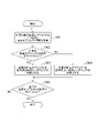
- FIG. 5 is an example of a flowchart showing the flow of determination information generation processing according to the present embodiment.
- the method of the determination information generation processing will be described assuming that it is performed based on the processing performance information of the user terminal described with reference to FIG. That is, when the computing performance of the user terminal is high and the data transfer rate is high, many foreground objects rendered depending on the virtual viewpoint are displayed in the virtual viewpoint image. On the other hand, when the computing performance of the user terminal is low and the data transfer rate is slow, it is expected that many foreground objects rendered independently of the virtual viewpoint will be displayed in the virtual viewpoint image.
- the data transfer speed is, for example, the transfer processing time of information required for each foreground object in virtual viewpoint-independent and virtual viewpoint-dependent rendering, but is not limited to this, and is the number of bytes that can be transferred per second ( Bps).
- the calculation performance is, for example, the calculation processing time required per foreground object in virtual viewpoint-independent and virtual viewpoint-dependent rendering, but is not limited to this. Flops). These calculations of transfer speed and computational performance may be performed for each frame, or may be performed during initialization before preparing verification data and using it to create a virtual viewpoint image. Further, the calculated transfer rate and calculation performance may be stored in the ROM 103 when the virtual viewpoint image generation processing is completed, and used when generating the next virtual viewpoint image. These transfer speeds and computational performance differ for each user's terminal. In this embodiment, in order to simplify the explanation, it is assumed that the transfer processing time and the arithmetic processing time are fixed times that do not change for each foreground object.
- the flow shown in FIG. 5 is executed by the determination unit 201. Triggered by reception of the data transfer rate input from the acquisition unit 203, the computing performance of the terminal input from the first image generation unit 205 and the second image generation unit 206, and the number of foreground objects input from the database 30 through the acquisition unit 203. , the flow of FIG. 5 is executed. However, if all the foreground objects are rendered independently of the virtual viewpoint, it is assumed that the total time of the transfer processing time and the arithmetic processing time is less than or equal to a predetermined threshold (13.3 msec at 60 fps). Also, let Th1 and Th2 be the thresholds for the computation processing time and the transfer processing time, respectively.
- the sum of Th1 and Th2 must be within 13.3 msec in order to generate a virtual viewpoint image at 60 fps.
- the flow of FIG. 5 explains in detail the control for generating determination information by determining the predetermined condition in S402 of FIG.
- the number n1 of foreground objects for which virtual viewpoint-dependent rendering is possible is calculated based on the transfer processing time threshold Th1.
- n1 For the method of calculating n1, for example, it is assumed that foreground objects are first rendered one by one depending on the virtual viewpoint. Then, the transfer processing time at that time is calculated. The maximum number of foreground objects for which the calculated transfer processing time does not exceed the threshold Th1 is n1. n1 may be determined by further considering the number of foreground objects to be rendered independent of the virtual viewpoint.
- the number n2 of foreground objects that can be rendered in a manner that depends on the virtual viewpoint is calculated based on the threshold value Th2 of the computation processing time.
- Th2 the threshold value of the computation processing time.
- foreground objects are first rendered one by one depending on the virtual viewpoint. Then, the arithmetic processing time at that time is calculated.
- the maximum number of foreground objects for which the calculated calculation interval does not exceed the threshold value Th2 is n2.
- n2 may be determined by further considering the number of foreground objects to be rendered independent of the virtual viewpoint.
- processing is divided according to n1 and n2 calculated in S503 and S504. Specifically, if n1 is smaller than n2, the process proceeds to S506, and if n1 is greater than or equal to n2, the process proceeds to S507.
- n1 foreground objects are randomly selected from N foreground objects for virtual viewpoint-dependent rendering, and Nn1 objects for virtual viewpoint-independent rendering.
- N foreground objects are subjected to virtual viewpoint dependent rendering.
- n2 foreground objects are randomly selected from N foreground objects for virtual viewpoint-dependent rendering, and Nn2 objects for virtual viewpoint-independent rendering.
- N foreground objects are subjected to virtual viewpoint dependent rendering.
- the determination information is information indicating the number of foreground objects to be subjected to virtual viewpoint dependent rendering.
- the determination information may also include ID information of the foreground object, which is randomly determined for the foreground object to be subjected to virtual viewpoint-dependent rendering.
- performance information indicating the processing performance of user terminals is acquired, and a process of selecting a rendering method for drawing a foreground object to be displayed in a virtual viewpoint image for each user terminal is performed. According to such processing, it is possible to generate a virtual viewpoint image while suppressing image quality deterioration in accordance with the processing performance of the user terminal.
- the determination unit 201 selects a rendering method for each foreground object, but the present invention is not limited to this. Instead of each foreground object, rendering may be performed for each part of an object, for example, a face depending on the virtual viewpoint, and rendering for other parts may be performed without depending on the virtual viewpoint.
- the background 3D model is rendered as one to which color information has been added in advance (independent of the virtual viewpoint), but is not limited to this. Based on this, it may be rendered by virtual viewpoint-dependent rendering.
- the determination unit 201 may determine to perform virtual-viewpoint-independent rendering under a predetermined condition.
- the user terminal generates the virtual viewpoint image, but the present invention is not limited to this, and the virtual viewpoint image may be generated by the server and transmitted to the user terminal via the Internet. In this case, a process of selecting a rendering method is performed according to the processing performance of the server.
- the shape information of the foreground object is described as a 3D point group, and the color information is a set of colors corresponding to the points, but the present invention is not limited to this.
- the shape information may be mesh data, and the color information may be a texture image (texture map) indicating color information for each polygon forming the mesh.
- Polygons may be triangles, quadrilaterals, or pentagons as long as they are polygons.
- polygon color information can be determined based on virtual viewpoint information in the same manner as in 3D point cloud.
- the computing performance and data transfer speed of the terminal are used as examples of the processing performance, but not limited to this, the usage rate of the CPU, memory, and network of the terminal is watched, and the usage rate is calculated. It may be a predetermined condition for determining the rendering method.
- three-dimensional shape information for example, 3D point cloud
- color information corresponding to each component constituting the three-dimensional shape information of the foreground object (corresponding to each point of the 3D point cloud) are stored.
- color information may be stored in separate files.
- the effect of reducing the data to be acquired can be obtained. For example, when the foreground object in the virtual viewpoint image is the target of virtual viewpoint independent rendering, it is not necessary to acquire the color information of the foreground object.
- the second image processing apparatus 40 only needs to acquire the file describing the shape information of the foreground object and the file of the captured image (or the foreground image) from the database 30, and obtain the color corresponding to the shape information of the foreground object. You don't have to get the file that describes the information.
- the database 30 may also store mesh data in addition to 3D point cloud data as shape information. Then, either the 3D point cloud or the mesh data may be transmitted to the second image processing device 40 based on the information of the second image processing device 40 and information such as the transmission band.
- Embodiment 2 In the first embodiment, a process of generating determination information based on the processing performance of a user terminal and the like and selecting a rendering method for drawing each foreground object to be displayed in a virtual viewpoint image has been described. Next, a mode of generating determination information based on the positional relationship between a foreground object and a virtual camera and selecting a rendering method for drawing each foreground object will be described as a second embodiment. Note that the description of the parts common to the first embodiment, such as the hardware configuration and functional configuration of the second image processing apparatus 40, will be omitted or simplified, and the following description will focus on the determination information generation control, which is the point of difference. and
- FIG. 6 is a schematic diagram displaying a virtual viewpoint image 601 in a soccer scene.
- FIG. 6 shows a virtual image obtained by generating determination information based on the positional relationship between a foreground object and a virtual camera, selecting a rendering method for rendering each foreground object, and rendering the foreground object with that rendering method, according to the present embodiment.
- 4 shows an example of a viewpoint image.
- FIG. 7 is a flow chart showing the process flow of the determination information generation method in the above selection.
- the predetermined condition for determining the rendering method for each foreground object is assumed to be the distance of the foreground object from the virtual camera. That is, a foreground object closer to the virtual camera is rendered dependent on the virtual viewpoint, and a foreground object farther than a certain distance from the virtual camera is rendered independent of the virtual viewpoint.
- the foreground object in front and the foreground object in the background are the same size in the real space, when perspective projection is performed on a two-dimensional image, the foreground object in the background is larger than the foreground object in the front. become smaller. Therefore, even if the image quality of the object in the background is lower than that of the foreground object in the foreground, the effect on the image is small, and the user's sense of discomfort is reduced.
- the flow in FIG. 7 is executed by the determination unit 201 in FIG. Execution of the flow in FIG. 7 is started with reception of virtual viewpoint information acquired from the virtual camera control unit 204 and position information of the foreground object from the database 30 through the acquisition unit 203 as a trigger.
- Th_d be a threshold value of the distance between the virtual camera and the foreground object, which is used as a condition for determining the rendering method for each foreground object.
- This distance threshold Th_d may be input by the user via the input device 50 and sent to the determination section 201 via the virtual camera control section 204 .
- this threshold value by the user, for example, when the frame rate is lowered, it is possible to make adjustments such as increasing the frame rate of the virtual viewpoint image by lowering the threshold value.
- the frame rate may be calculated as needed, and the threshold value Th_d may be automatically increased or decreased so as not to reduce the frame rate.
- the flow of FIG. 7 explains in detail the control for generating determination information based on the determination of the predetermined condition in S402 of FIG.
- one foreground object to be determined is specified, and its position information is acquired.
- the position information of the foreground object is assumed to be the three-dimensional position of the center of gravity of the foreground object in the virtual space, but is not limited to this, and may be the position of any vertex of the bounding box of the foreground object.
- the distance D between the virtual camera and the foreground object is calculated based on the virtual viewpoint information and the position information of the foreground object.
- the position information of the virtual camera is specified based on virtual viewpoint information input by the user via the input device 50 .
- processing is divided according to the distance D calculated in S702 and the distance threshold Th_d. Specifically, if the distance D is smaller than the threshold Th_d, the process proceeds to S704, and if the distance D is equal to or greater than the threshold Th_d, the process proceeds to S705.
- the foreground object to be determined is determined to be the target of virtual viewpoint dependent rendering.
- the foreground object to be determined is determined to be the target of virtual viewpoint independent rendering.
- the determination unit 201 When this flow ends, the determination unit 201 generates determination information indicating which foreground object is the target of virtual viewpoint dependent rendering.
- the determination information may be ID information of a foreground object with a flag indicating that the foreground object is subject to virtual viewpoint dependent rendering.
- the determination information may include an information element storing ID information of the foreground object and an information element indicating whether or not the object is a target for virtual viewpoint dependent rendering. Then, when "1" is stored in the information element indicating whether or not the foreground object is to be subjected to virtual viewpoint dependent rendering corresponding to the information element storing the ID information of the foreground object, the foreground object is subjected to virtual viewpoint dependent rendering. It may indicate that it is subject to In this case, when the foreground object is the target of virtual viewpoint independent rendering, a value other than "1" is stored in the information element indicating whether or not the foreground object is the target of virtual viewpoint dependent rendering.
- the above is the content of the control for generating determination information based on the positional relationship between the foreground object and the virtual camera and selecting the rendering method for drawing each foreground object according to the present embodiment. According to such processing, it is possible to generate a virtual viewpoint image having image quality suitable for the user's terminal while reducing the processing load.
- the determination unit 201 performs determination based on the distance between the virtual camera and the foreground object, but the present invention is not limited to this.
- the size of the foreground object on the image may be calculated by taking into consideration not only the distance but also the focal length of the virtual camera, and the determination may be made based on this calculation. For example, even if the foreground object is far from the virtual camera, if the virtual camera is set to telephoto, the foreground object may be determined to be the target of virtual viewpoint dependent rendering. On the other hand, if the setting is wide-angle, the foreground object may be determined to be the target of virtual viewpoint-independent rendering.
- determination may be made not only by the distance between the virtual camera and the foreground object, but also by the position on the virtual viewpoint image. For example, if the foreground object is located near the center of the virtual viewpoint image, the foreground object may be determined to be the target of virtual viewpoint dependent rendering. On the other hand, if the foreground object is located in the periphery on the virtual viewpoint image, the foreground object may be determined to be the target of virtual viewpoint independent rendering.
- This embodiment may be combined with the first embodiment. For example, in the first embodiment, after determining the number of foreground objects to be subjected to virtual viewpoint dependent rendering in S506 and S507 of FIG. good. The determination of which foreground objects to target for virtual viewpoint dependent rendering may be made based on the positional relationship between the foreground objects and the virtual viewpoint.
- the processing after S506 and S507 in FIG. 5 may have the following configuration. That is, the distance between the foreground object and the virtual viewpoint is calculated for each foreground object.
- the foreground object is determined to be the target of virtual viewpoint dependent rendering in order of proximity to the virtual viewpoint. However, this is performed until the number of foreground objects to be subjected to virtual viewpoint dependent rendering determined in S506 and S507 of FIG. 5 is reached. In this case, there is no need to provide a distance threshold. It should be noted that the determination may be made based on the positional information of the foreground object and the virtual viewpoint without calculating the distance between the foreground object and the virtual viewpoint.
- the foreground objects may be determined to be the targets of virtual viewpoint dependent rendering based on their positions on the virtual viewpoint image. good. Specifically, in the virtual viewpoint image, it may be determined that the foreground objects are to be subjected to virtual viewpoint dependent rendering in order of proximity to the center of the image. In this case as well, the number of foreground objects to be subjected to virtual viewpoint dependent rendering determined in S506 and S507 of FIG. 5 is reached.
- Embodiment 3 In this embodiment, the type of foreground object (each player, ball, etc.) is identified, determination information is generated based on a predetermined foreground object specified by the user, and each foreground object to be displayed in the virtual viewpoint image is drawn. Aspects of selecting a rendering method are described. Note that the description of the parts common to the first embodiment, such as the hardware configuration and functional configuration of the second image processing apparatus 40, will be omitted or simplified, and the following description will focus on the determination information generation control, which is the point of difference. is.
- FIG. 8 is a schematic diagram displaying a virtual viewpoint image 801 in a soccer scene.
- FIG. 8 shows an example according to the present embodiment, in which determination information is generated based on whether or not a foreground object is specified by a user, a rendering method for rendering each foreground object is selected, and each foreground object is rendered using the selected rendering method.
- 4 shows an example of a virtual viewpoint image that has been processed.
- FIG. 9 is a flow chart showing the process flow of the determination information generation method in the above selection.
- the predetermined condition for determining the rendering method for each foreground object is whether or not it is the target foreground object specified by the user. That is, a target specified by the user, for example, a foreground object of player A that the user wants to focus on, is rendered in a virtual viewpoint dependent manner, and other players are rendered in a virtual viewpoint independent manner.
- a target specified by the user for example, a foreground object of player A that the user wants to focus on
- other players are rendered in a virtual viewpoint independent manner.
- the virtual viewpoint image 801 of FIG. 8 only the player A 802 of interest to the user is rendered in a virtual viewpoint-dependent manner.
- the flow in FIG. 9 is executed by the determination unit 201. Execution of the flow of FIG. 9 is started with reception of virtual viewpoint information acquired from the virtual camera control unit 204 and reception of foreground object information from the database 30 through the acquisition unit 203 as triggers. However, it is assumed that the object-of-interest information specified by the user has been previously sent to the determination unit 201 through the virtual camera control unit 204 using the input device 50 .
- the flow of FIG. 9 describes in detail the control for generating the judgment information by judging the predetermined condition in 402 of FIG.
- one foreground object to be determined is specified and its foreground object information is acquired.
- the processing is divided according to the foreground object information and the target object information. Specifically, if the target foreground object is the target object, the process proceeds to S903, and if not, the process proceeds to S904.
- S903 to S905 are the same as S704 to S706 in FIG.
- the determination unit 201 When this flow ends, the determination unit 201 generates determination information indicating which foreground object is the target of virtual viewpoint dependent rendering.
- the determination information may be ID information of a foreground object with a flag indicating that the foreground object is subject to virtual viewpoint dependent rendering.
- the determination information may include an information element storing ID information of the foreground object and an information element indicating whether or not the object is a target for virtual viewpoint dependent rendering. Then, when "1" is stored in the information element indicating whether or not the foreground object is to be subjected to virtual viewpoint dependent rendering corresponding to the information element storing the ID information of the foreground object, the foreground object is subjected to virtual viewpoint dependent rendering. It may indicate that it is subject to In this case, when the foreground object is the target of virtual viewpoint independent rendering, a value other than "1" is stored in the information element indicating whether or not the foreground object is the target of virtual viewpoint dependent rendering.
- the above is the content of control for generating determination information based on whether or not a foreground object is a predetermined foreground object specified by the user and selecting a rendering method for drawing each foreground object according to the present embodiment. According to such processing, it is possible to generate a virtual viewpoint image in which a foreground object that the user wants to focus on is rendered with high image quality.
- the explanation was given on the assumption that the number of predetermined foreground objects designated by the user is one, but the user may designate a plurality of foreground objects without being limited to this. Also, the user may designate an object (non-target object) that is not to be the target object. Also, the user may specify whether each foreground object should be an object of interest.
- the user may specify the object of interest on a category-by-category basis. For example, the user may designate all foreground objects included in the same team as objects of interest. Therefore, it is also possible to specify a target object by specifying a team.
- the user may also specify a partial area (area in front of the goal, area near the center circle, etc.) within the imaging target area.
- a foreground object included in an area specified by the user may be set as the object of interest.
- S902 it may be determined whether or not the foreground object is included in the area specified by the user, and if Yes, the process proceeds to S903, and if No, the process proceeds to S904. .
- the user may input attention object information when inputting virtual viewpoint information via the input device 40 .
- information indicating whether the object is the object of interest is not included in the foreground object information in advance.
- the present disclosure provides a program that implements one or more functions of the above-described embodiments to a system or device via a network or storage medium, and one or more processors in a computer of the system or device reads and executes the program. It can also be realized by processing to It can also be implemented by a circuit (for example, ASIC) that implements one or more functions.
- a circuit for example, ASIC
Landscapes
- Engineering & Computer Science (AREA)
- Physics & Mathematics (AREA)
- Theoretical Computer Science (AREA)
- Multimedia (AREA)
- Signal Processing (AREA)
- General Physics & Mathematics (AREA)
- Computer Vision & Pattern Recognition (AREA)
- Computing Systems (AREA)
- Geometry (AREA)
- Computer Graphics (AREA)
- Processing Or Creating Images (AREA)
Abstract
Description
実施形態1では、ユーザ端末の処理性能、つまり演算性能やデータの転送速度に基づいて、レンダリング方法を決定する処理を説明する。
図1Aは、本実施形態に係る、画像処理システムの全体構成の一例を示す図である。画像処理システム1は、複数の撮像装置による撮像に基づく複数の画像と、指定された仮想視点とに基づいて、指定された仮想視点からの見えを表す仮想視点画像を生成するシステムである。画像処理システム1は、ユーザ端末の演算性能やデータの転送速度を示す処理性能情報を取得し、処理性能情報に応じてレンダリング方法を決定する。そして、画像処理システム1は、決定したレンダリング方法に基づき仮想視点画像を生成し出力する。画像処理システム1は、撮影システム10、第1の画像処理装置20、データベース30、第2の画像処理装置40、入力装置50、及び表示装置60を有する。
図2は、第2の画像処理装置40の、所定条件の判定に従って、前景オブジェクトごとにレンダリング方法を決定する処理に係る機能構成の一例を示す図である。
図3は、ユーザ端末の処理性能の違いにより異なるレンダリング方法で生成した仮想視点画像の概略図である。図3は、2つの端末(ハイスペックPC302、タブレット303)を用いて、サッカーのシーンにおける仮想視点画像を表示している概略図である。ハイスペックPC302、タブレット303は、第2の画像処理装置に対応する。ユーザが所有する端末は、インターネットを介して、DB301(データベース30に対応)にアクセスする。そして、端末は、仮想視点画像を生成する上で必要なデータを取得し、ハイスペックPC302、タブレット303でそれぞれ仮想視点画像304、仮想視点画像305を生成する。
図4は、本実施形態に係る、所定条件の判定とその判定結果に基づく仮想視点画像の生成を制御する処理の流れを示すフローチャートである。図4に示すフローは、ROM103に格納された制御プログラムがRAM102に読み出され、CPU101がこれを実行することによって実現される。第2の画像処理装置40が有する仮想カメラ制御部204が入力装置からの入力値の受信をトリガとして、図4のフローの実行が開始される。
図5は、本実施形態に係る、判定情報の生成処理の流れを示すフローチャートの一例である。ここでは、判定情報の生成処理の方法は、図3を用いて説明したユーザ端末の処理性能情報に基づき行う場合で説明する。すなわち、ユーザ端末の演算性能が高くデータの転送速度が速い場合は、仮想視点画像に仮想視点依存でレンダリングした前景オブジェクトが多く表示される。一方、ユーザ端末の演算性能が低くデータの転送速度が遅い場合は、仮想視点画像に仮想視点非依存でレンダリングした前景オブジェクトが多く表示されることが期待される。データの転送速度は、例えば、仮想視点非依存、仮想視点依存のレンダリングにおける前景オブジェクト1個あたりに必要な情報の転送処理時間であるが、これに限らず、1秒間に転送可能なByte数(Bps)でもよい。演算性能は、例えば、仮想視点非依存、仮想視点依存のレンダリングにおける前景オブジェクト1個あたりに必要な演算処理時間であるが、これに限らず、CPUが1秒間に小数点演算を何回できるか(Flops)でもよい。これら、転送速度や演算性能の計算は、毎フレーム行ってもよいし、検証用のデータを用意しそれを使って仮想視点画像を作成する前の初期化時に行ってもよい。また、計算した転送速度や演算性能は仮想視点画像の生成処理の終了時にROM103に保存しておき、次回仮想視点画像を生成する際に利用してもよい。これら転送速度と演算性能がユーザの端末ごとに異なる。なお、本実施形態では、説明を分かりやすく簡略化するために、転送処理時間と演算処理時間は前景オブジェクトごとに変化しない一定の時間と仮定する。
実施形態1では、ユーザ端末の処理性能等に基づいて判定情報を生成し、仮想視点画像に表示する前景オブジェクトごとに描画するレンダリング方法を選択する処理を説明した。次に、前景オブジェクトと仮想カメラの位置関係に基づいて判定情報を生成し、前景オブジェクトごとに描画するレンダリング方法を選択する態様を、実施形態2として説明する。なお、第2の画像処理装置40のハードウェア構成や機能構成など実施形態1と共通する部分は説明を省略ないしは簡略化し、以下では差異点である判定情報の生成制御を中心に説明を行うものとする。
本実施形態は、実施形態1と組み合わせてもよい。例えば、実施形態1において、図5のS506やS507において、仮想視点依存レンダリングの対象となる前景オブジェクトの数を決定した後に、どの前景オブジェクトを仮想視点依存レンダリングの対象とするかを決定してもよい。どの前景オブジェクトを仮想視点依存レンダリングの対象とするかの決定は、前景オブジェクトと仮想視点との位置関係に基づいて行われてもよい。
本実施形態では、前景オブジェクトの種別(選手ごと、ボールなど)を識別して、ユーザが指定した所定の前景オブジェクトに基づいて判定情報を生成し、仮想視点画像に表示する前景オブジェクトごとに描画するレンダリング方法を選択する態様を説明する。なお、第2の画像処理装置40のハードウェア構成や機能構成など実施形態1と共通する部分は説明を省略ないしは簡略化し、以下では差異点である判定情報の生成制御を中心に説明を行うものである。
本開示は、上述の実施形態の1以上の機能を実現するプログラムを、ネットワーク又は記憶媒体を介してシステム又は装置に供給し、そのシステム又は装置のコンピュータにおける1つ以上のプロセッサがプログラムを読出し実行する処理でも実現可能である。また、1以上の機能を実現する回路(例えば、ASIC)によっても実現可能である。
Claims (19)
- 仮想視点の位置及び仮想視点からの視線方向を特定するための仮想視点情報を取得する取得手段と、
オブジェクトに対して、前記取得手段により取得された仮想視点情報と、前記オブジェクトの3次元形状を特定するための形状情報と、複数の撮像装置により取得された画像とに基づいて色を決定する第1の方法と、前記オブジェクトの3次元形状を特定するための形状情報と、前記形状情報の構成要素に対応する色を特定する色情報であって、前記仮想視点からの視線方向によって変化しない色情報とに基づいて色を決定する第2の方法のうち一方を選択する選択手段と、
前記選択手段により選択された方法に基づいて色が決められたオブジェクトを含み、前記取得手段により取得された仮想視点情報により特定される仮想視点からの見えを示す仮想視点画像を生成する生成手段と、を有することを特徴とする画像処理装置。 - 前記選択手段は、オブジェクトごとに、色を決定する方法を選択することを特徴とする請求項1に記載の画像処理装置。
- 前記選択手段は、オブジェクトごとに、前記取得手段により取得された仮想視点情報に基づいて、色を決定する方法を選択することを特徴とする請求項2に記載の画像処理装置。
- 前記選択手段は、オブジェクトごとに、前記取得手段により取得された仮想視点情報により特定される仮想視点の位置とオブジェクトの位置に基づいて、色を決定する方法を選択することを特徴とする請求項3に記載の画像処理装置。
- 前記仮想視点情報は、前記仮想視点の焦点距離を特定するための情報を有し、
前記選択手段は、オブジェクトごとに、前記取得手段により取得された仮想視点情報により特定される仮想視点の焦点距離に基づいて、色を決定する方法を選択することを特徴とする請求項3又は4に記載の画像処理装置。 - 前記選択手段は、オブジェクトごとに、前記仮想視点画像におけるオブジェクトの位置に基づいて、色を決定する方法を選択することを特徴とする請求項2乃至5のいずれか1項に記載の画像処理装置。
- 前記選択手段は、オブジェクトが、注目オブジェクトであるかに基づいて、色を決定する方法を選択することを特徴とする請求項1に記載の画像処理装置。
- 選択手段は、オブジェクトが、注目オブジェクトである場合、前記オブジェクトの色を決定する方法として前記第1の方法を選択することを特徴とする請求項7に記載の画像処理装置。
- 前記注目オブジェクトは、ユーザにより指定されることを特徴とする請求項7又は8に記載の画像処理装置。
- 前記選択手段は、前記第1の方法により色が決定されるオブジェクトの数を決定することを特徴とする請求項1に記載の画像処理装置。
- 前記選択手段は、前記第1の方法により色が決定されるオブジェクトの数と、前記取得手段により取得された仮想視点情報により特定される仮想視点の位置に基づいて、前記第1の方法を用いるオブジェクトを選択することを特徴とする請求項10に記載の画像処理装置。
- 前記選択手段は、前記生成手段の処理性能に基づいて、色を決定する方法を選択することを特徴とする請求項1乃至11のいずれか1項に記載の画像処理装置。
- 前記取得手段は、前記選択手段により選択された方法に基づいて、前記仮想視点画像の生成に用いられるデータを、他の装置から取得することを特徴とする請求項1乃至12のいずれか1項に記載の画像処理装置。
- 前記取得手段は、
前記選択手段により前記第1の方法が選択された場合、前記他の装置から、前記第1の方法により色が決定されるオブジェクトの3次元形状を特定するための形状情報と、前記複数の撮像装置により取得された画像とを取得し、
前記選択手段により前記第2の方法が選択された場合、前記他の装置から、前記第2の方法により色が決定されたオブジェクトの3次元形状を特定するための形状情報と、前記形状情報の構成要素に対応する色を特定する色情報とを取得することを特徴とする請求項13に記載の画像処理装置。 - 前記選択手段は、前記他の装置との通信環境に基づいて、色を決定する方法を選択することを特徴とする請求項13に記載の画像処理装置。
- 前記仮想視点画像には、前記第1の方法により色が決定されたオブジェクトと前記第2の方法により色が決定されたオブジェクトとが含まれることを特徴とする請求項1乃至15のいずれか1項に記載の画像処理装置。
- 前記形状情報が点群で表現されるデータであり、前記色情報は、前記点群を構成する点に対応する色を特定するデータであることを特徴とする請求項1乃至16のいずれか1項に記載の画像処理装置。
- 仮想視点の位置及び仮想視点からの視線方向を特定するための仮想視点情報を取得する取得工程と、
オブジェクトに対して、前記取得工程により取得された仮想視点情報と、前記オブジェクトの3次元形状を特定するための形状情報と、複数の撮像装置により取得された画像とに基づいて色を決定する第1の方法と、前記オブジェクトの3次元形状を特定するための形状情報と、前記形状情報の構成要素に対応する色を特定する色情報であって、前記仮想視点からの視線方向によって変化しない色情報とに基づいて色を決定する第2の方法のうち一方を選択する選択工程と、
前記選択工程により選択された方法に基づいて色が決められたオブジェクトを含み、前記取得工程により取得された仮想視点情報により特定される仮想視点からの見えを示す仮想視点画像を生成する生成工程と、を有することを特徴とする画像処理方法。 - コンピュータを、請求項1乃至17のいずれか1項に記載の画像処理装置として機能させるためのプログラム。
Priority Applications (2)
| Application Number | Priority Date | Filing Date | Title |
|---|---|---|---|
| EP22756040.6A EP4296961A4 (en) | 2021-02-18 | 2022-02-09 | IMAGE PROCESSING DEVICE, IMAGE PROCESSING METHOD AND PROGRAM |
| US18/450,049 US12610035B2 (en) | 2021-02-18 | 2023-08-15 | Image processing apparatus, image processing method, and storage medium |
Applications Claiming Priority (2)
| Application Number | Priority Date | Filing Date | Title |
|---|---|---|---|
| JP2021024135A JP2022126206A (ja) | 2021-02-18 | 2021-02-18 | 画像処理装置、画像処理方法及びプログラム |
| JP2021-024135 | 2021-02-18 |
Related Child Applications (1)
| Application Number | Title | Priority Date | Filing Date |
|---|---|---|---|
| US18/450,049 Continuation US12610035B2 (en) | 2021-02-18 | 2023-08-15 | Image processing apparatus, image processing method, and storage medium |
Publications (1)
| Publication Number | Publication Date |
|---|---|
| WO2022176719A1 true WO2022176719A1 (ja) | 2022-08-25 |
Family
ID=82930604
Family Applications (1)
| Application Number | Title | Priority Date | Filing Date |
|---|---|---|---|
| PCT/JP2022/004991 Ceased WO2022176719A1 (ja) | 2021-02-18 | 2022-02-09 | 画像処理装置、画像処理方法及びプログラム |
Country Status (4)
| Country | Link |
|---|---|
| US (1) | US12610035B2 (ja) |
| EP (1) | EP4296961A4 (ja) |
| JP (1) | JP2022126206A (ja) |
| WO (1) | WO2022176719A1 (ja) |
Families Citing this family (2)
| Publication number | Priority date | Publication date | Assignee | Title |
|---|---|---|---|---|
| US12519924B2 (en) * | 2022-08-31 | 2026-01-06 | Snap Inc. | Multi-perspective augmented reality experience |
| EP4443273A1 (en) * | 2023-03-31 | 2024-10-09 | Canon Kabushiki Kaisha | Display control apparatus, display control method, and program |
Citations (5)
| Publication number | Priority date | Publication date | Assignee | Title |
|---|---|---|---|---|
| JP2014010804A (ja) | 2012-07-03 | 2014-01-20 | Nippon Telegr & Teleph Corp <Ntt> | 画像処理装置、画像処理方法及び画像処理プログラム |
| JP2020008972A (ja) * | 2018-07-04 | 2020-01-16 | キヤノン株式会社 | 情報処理装置、情報処理方法及びプログラム |
| JP2020042666A (ja) * | 2018-09-12 | 2020-03-19 | キヤノン株式会社 | 画像生成装置、画像生成装置の制御方法及びプログラム |
| JP2020135290A (ja) * | 2019-02-18 | 2020-08-31 | キヤノン株式会社 | 画像生成装置、画像生成方法、画像生成システム、及びプログラム |
| JP2021024135A (ja) | 2019-07-31 | 2021-02-22 | キヤノン株式会社 | 記録装置、制御方法、及びプログラム |
Family Cites Families (233)
| Publication number | Priority date | Publication date | Assignee | Title |
|---|---|---|---|---|
| US20150297949A1 (en) * | 2007-06-12 | 2015-10-22 | Intheplay, Inc. | Automatic sports broadcasting system |
| US7844076B2 (en) * | 2003-06-26 | 2010-11-30 | Fotonation Vision Limited | Digital image processing using face detection and skin tone information |
| HU0401034D0 (en) * | 2004-05-24 | 2004-08-30 | Ratai Daniel | System of three dimension induting computer technology, and method of executing spatial processes |
| US8130260B2 (en) * | 2005-11-09 | 2012-03-06 | Johns Hopkins University | System and method for 3-dimensional display of image data |
| US8197070B2 (en) * | 2006-01-24 | 2012-06-12 | Seiko Epson Corporation | Color-based feature identification |
| JP4847184B2 (ja) * | 2006-04-06 | 2011-12-28 | キヤノン株式会社 | 画像処理装置及びその制御方法、プログラム |
| US8411149B2 (en) * | 2006-08-03 | 2013-04-02 | Alterface S.A. | Method and device for identifying and extracting images of multiple users, and for recognizing user gestures |
| WO2008144843A1 (en) * | 2007-05-31 | 2008-12-04 | Depth Analysis Pty Ltd | Systems and methods for applying a 3d scan of a physical target object to a virtual environment |
| US7928980B2 (en) * | 2007-07-19 | 2011-04-19 | Analytical Graphics Inc. | Method for visualizing data clouds using color and opacity blending |
| JP2009159224A (ja) * | 2007-12-26 | 2009-07-16 | Nikon Corp | 画像データ記録装置、画像処理装置、およびカメラ |
| ES2389401T3 (es) * | 2008-06-17 | 2012-10-25 | Huawei Device Co., Ltd. | Método, aparato y sistema de comunicación a través de vídeo |
| US8106924B2 (en) * | 2008-07-31 | 2012-01-31 | Stmicroelectronics S.R.L. | Method and system for video rendering, computer program product therefor |
| JP5243612B2 (ja) * | 2008-10-02 | 2013-07-24 | フラウンホッファー−ゲゼルシャフト ツァ フェルダールング デァ アンゲヴァンテン フォアシュンク エー.ファオ | 中間画像合成およびマルチビューデータ信号抽出 |
| US20110025834A1 (en) * | 2009-07-31 | 2011-02-03 | Samsung Electronics Co., Ltd. | Method and apparatus of identifying human body posture |
| US20110075257A1 (en) * | 2009-09-14 | 2011-03-31 | The Arizona Board Of Regents On Behalf Of The University Of Arizona | 3-Dimensional electro-optical see-through displays |
| US10375287B2 (en) * | 2009-10-21 | 2019-08-06 | Disney Enterprises, Inc. | Object trail-based analysis and control of video |
| US8817071B2 (en) * | 2009-11-17 | 2014-08-26 | Seiko Epson Corporation | Context constrained novel view interpolation |
| US8643701B2 (en) * | 2009-11-18 | 2014-02-04 | University Of Illinois At Urbana-Champaign | System for executing 3D propagation for depth image-based rendering |
| WO2011121117A1 (en) * | 2010-04-02 | 2011-10-06 | Imec | Virtual camera system |
| KR101697184B1 (ko) * | 2010-04-20 | 2017-01-17 | 삼성전자주식회사 | 메쉬 생성 장치 및 그 방법, 그리고, 영상 처리 장치 및 그 방법 |
| KR101669820B1 (ko) * | 2010-07-02 | 2016-10-27 | 삼성전자주식회사 | 볼륨 예측 기반 폐색 영역 양방향 복원 장치 및 방법 |
| EP2413286A1 (en) * | 2010-07-29 | 2012-02-01 | LiberoVision AG | Image processing method and device for instant replay |
| GB2489675A (en) * | 2011-03-29 | 2012-10-10 | Sony Corp | Generating and viewing video highlights with field of view (FOV) information |
| US20130095920A1 (en) * | 2011-10-13 | 2013-04-18 | Microsoft Corporation | Generating free viewpoint video using stereo imaging |
| US9563723B1 (en) * | 2011-10-30 | 2017-02-07 | Lockheed Martin Corporation | Generation of an observer view in a virtual environment |
| US10321142B2 (en) * | 2013-07-15 | 2019-06-11 | Samsung Electronics Co., Ltd. | Method and apparatus for video encoding for adaptive illumination compensation, method and apparatus for video decoding for adaptive illumination compensation |
| GB2523555B (en) * | 2014-02-26 | 2020-03-25 | Sony Interactive Entertainment Europe Ltd | Image encoding and display |
| WO2015167739A1 (en) * | 2014-04-30 | 2015-11-05 | Replay Technologies Inc. | System for and method of generating user-selectable novel views on a viewing device |
| KR101687017B1 (ko) * | 2014-06-25 | 2016-12-16 | 한국과학기술원 | 머리 착용형 컬러 깊이 카메라를 활용한 손 위치 추정 장치 및 방법, 이를 이용한 맨 손 상호작용 시스템 |
| US9418472B2 (en) * | 2014-07-17 | 2016-08-16 | Google Inc. | Blending between street view and earth view |
| GB201414144D0 (en) * | 2014-08-08 | 2014-09-24 | Imagination Tech Ltd | Relightable texture for use in rendering an image |
| US10008027B1 (en) * | 2014-10-20 | 2018-06-26 | Henry Harlyn Baker | Techniques for determining a three-dimensional representation of a surface of an object from a set of images |
| US10176592B2 (en) * | 2014-10-31 | 2019-01-08 | Fyusion, Inc. | Multi-directional structured image array capture on a 2D graph |
| US20160140748A1 (en) * | 2014-11-14 | 2016-05-19 | Lytro, Inc. | Automated animation for presentation of images |
| US9576399B2 (en) * | 2014-12-23 | 2017-02-21 | Meta Company | Apparatuses, methods and systems coupling visual accommodation and visual convergence to the same plane at any depth of an object of interest |
| US9824498B2 (en) * | 2014-12-30 | 2017-11-21 | Sony Interactive Entertainment Inc. | Scanning display system in head-mounted display for virtual reality |
| US10003786B2 (en) * | 2015-09-25 | 2018-06-19 | Intel Corporation | Method and system of 3D image capture with dynamic cameras |
| US9445081B1 (en) * | 2015-09-25 | 2016-09-13 | Intel Corporation | Method and system of 3D image capture with dynamic cameras |
| KR101781942B1 (ko) * | 2016-03-08 | 2017-10-23 | 숭실대학교산학협력단 | 홀 채움 방법, 이를 수행하기 위한 기록매체 및 장치 |
| JP6088094B1 (ja) * | 2016-06-20 | 2017-03-01 | 株式会社Cygames | 複合現実環境を作成するためのシステム等 |
| US10129523B2 (en) * | 2016-06-22 | 2018-11-13 | Microsoft Technology Licensing, Llc | Depth-aware reprojection |
| WO2018030206A1 (ja) * | 2016-08-10 | 2018-02-15 | パナソニック インテレクチュアル プロパティ コーポレーション オブ アメリカ | カメラワーク生成方法及び映像処理装置 |
| US10559095B2 (en) * | 2016-08-31 | 2020-02-11 | Canon Kabushiki Kaisha | Image processing apparatus, image processing method, and medium |
| JP6918455B2 (ja) * | 2016-09-01 | 2021-08-11 | キヤノン株式会社 | 画像処理装置、画像処理方法及びプログラム |
| EP3300022B1 (en) * | 2016-09-26 | 2019-11-06 | Canon Kabushiki Kaisha | Image processing apparatus, image processing method, and program |
| JP6812181B2 (ja) * | 2016-09-27 | 2021-01-13 | キヤノン株式会社 | 画像処理装置、画像処理方法、及び、プログラム |
| US11127194B2 (en) * | 2016-10-25 | 2021-09-21 | Sony Corporation | Image processing apparatus and image processing method |
| US10430994B1 (en) * | 2016-11-07 | 2019-10-01 | Henry Harlyn Baker | Techniques for determining a three-dimensional textured representation of a surface of an object from a set of images with varying formats |
| US10217243B2 (en) * | 2016-12-20 | 2019-02-26 | Canon Kabushiki Kaisha | Method, system and apparatus for modifying a scene model |
| JP6849430B2 (ja) * | 2016-12-27 | 2021-03-24 | キヤノン株式会社 | 画像処理装置、画像処理方法、及びプログラム |
| JP7320352B2 (ja) * | 2016-12-28 | 2023-08-03 | パナソニック インテレクチュアル プロパティ コーポレーション オブ アメリカ | 三次元モデル送信方法、三次元モデル受信方法、三次元モデル送信装置及び三次元モデル受信装置 |
| JP6878014B2 (ja) * | 2017-01-13 | 2021-05-26 | キヤノン株式会社 | 画像処理装置及びその方法、プログラム、画像処理システム |
| US11665308B2 (en) * | 2017-01-31 | 2023-05-30 | Tetavi, Ltd. | System and method for rendering free viewpoint video for sport applications |
| JP7159057B2 (ja) * | 2017-02-10 | 2022-10-24 | パナソニック インテレクチュアル プロパティ コーポレーション オブ アメリカ | 自由視点映像生成方法及び自由視点映像生成システム |
| JP6341396B1 (ja) * | 2017-02-28 | 2018-06-13 | パナソニックIpマネジメント株式会社 | 動体監視装置、サーバ装置、および動体監視システム |
| DE102017203721A1 (de) * | 2017-03-07 | 2018-09-13 | Bitmanagement Software GmbH | Vorrichtung und Verfahren zur Darstellung eines Raumbilds von einem Objekt in einer virtuellen Umgebung |
| US20230107110A1 (en) * | 2017-04-10 | 2023-04-06 | Eys3D Microelectronics, Co. | Depth processing system and operational method thereof |
| WO2018201048A1 (en) * | 2017-04-27 | 2018-11-01 | Google Llc | Synthetic stereoscopic content capture |
| KR102006064B1 (ko) * | 2017-06-09 | 2019-07-31 | 숭실대학교산학협력단 | 추정된 시공간 배경 정보를 이용한 홀 채움 방법, 이를 수행하기 위한 기록매체 및 장치 |
| US10181192B1 (en) * | 2017-06-30 | 2019-01-15 | Canon Kabushiki Kaisha | Background modelling of sport videos |
| US11004264B2 (en) * | 2017-08-07 | 2021-05-11 | Verizon Patent And Licensing Inc. | Systems and methods for capturing, transferring, and rendering viewpoint-adaptive three-dimensional (3D) personas |
| US11095854B2 (en) * | 2017-08-07 | 2021-08-17 | Verizon Patent And Licensing Inc. | Viewpoint-adaptive three-dimensional (3D) personas |
| EP3675060A4 (en) * | 2017-08-22 | 2020-08-26 | Sony Corporation | IMAGE PROCESSING DEVICE AND IMAGE PROCESSING METHOD |
| JP6921686B2 (ja) * | 2017-08-30 | 2021-08-18 | キヤノン株式会社 | 生成装置、生成方法、及びプログラム |
| US10846934B2 (en) * | 2017-10-03 | 2020-11-24 | ExtendView Inc. | Camera-based object tracking and monitoring |
| CN114777682A (zh) * | 2017-10-06 | 2022-07-22 | 先进扫描仪公司 | 生成一个或多个亮度边缘以形成物体的三维模型 |
| US10412435B2 (en) * | 2017-11-15 | 2019-09-10 | Whatsapp Inc. | Techniques to dynamically engage a reduced-color mode for streaming video encoding |
| JP7109907B2 (ja) * | 2017-11-20 | 2022-08-01 | キヤノン株式会社 | 画像処理装置、画像処理方法およびプログラム |
| US10529086B2 (en) * | 2017-11-22 | 2020-01-07 | Futurewei Technologies, Inc. | Three-dimensional (3D) reconstructions of dynamic scenes using a reconfigurable hybrid imaging system |
| US10528820B2 (en) * | 2017-12-07 | 2020-01-07 | Canon Kabushiki Kaisha | Colour look-up table for background segmentation of sport video |
| JP7081142B2 (ja) * | 2017-12-26 | 2022-06-07 | 富士通株式会社 | 情報処理装置、情報処理方法、及びプログラム |
| JP7051457B2 (ja) * | 2018-01-17 | 2022-04-11 | キヤノン株式会社 | 画像処理装置、画像処理方法、及びプログラム |
| JP2019128641A (ja) * | 2018-01-22 | 2019-08-01 | キヤノン株式会社 | 画像処理装置、画像処理方法及びプログラム |
| JP2019144958A (ja) * | 2018-02-22 | 2019-08-29 | キヤノン株式会社 | 画像処理装置、画像処理方法およびプログラム |
| US20200402310A1 (en) * | 2018-02-26 | 2020-12-24 | Mitsubishi Electric Corporation | Virtual object display control device, virtual object display system, virtual object display control method, and storage medium storing virtual object display control program |
| US10902676B2 (en) * | 2018-03-13 | 2021-01-26 | Canon Kabushiki Kaisha | System and method of controlling a virtual camera |
| KR20200144097A (ko) * | 2018-04-12 | 2020-12-28 | 도판 인사츠 가부시키가이샤 | 라이트 필드 화상 생성 시스템, 화상 표시 시스템, 형상 정보 취득 서버, 화상 생성 서버, 표시 장치, 라이트 필드 화상 생성 방법 및 화상 표시 방법 |
| JP2019191989A (ja) * | 2018-04-26 | 2019-10-31 | キヤノン株式会社 | 仮想視点画像を生成するシステム、方法及びプログラム |
| JP7062506B2 (ja) * | 2018-05-02 | 2022-05-06 | キヤノン株式会社 | 画像処理装置、画像処理方法、およびプログラム |
| US10638151B2 (en) * | 2018-05-31 | 2020-04-28 | Verizon Patent And Licensing Inc. | Video encoding methods and systems for color and depth data representative of a virtual reality scene |
| JP7187182B2 (ja) * | 2018-06-11 | 2022-12-12 | キヤノン株式会社 | データ生成装置、方法およびプログラム |
| JP2020003898A (ja) * | 2018-06-26 | 2020-01-09 | ソニー株式会社 | 情報処理装置、情報処理方法、及びプログラム |
| JP7193938B2 (ja) * | 2018-07-04 | 2022-12-21 | キヤノン株式会社 | 情報処理装置及びその制御方法、プログラム |
| TWI675583B (zh) * | 2018-07-23 | 2019-10-21 | 緯創資通股份有限公司 | 擴增實境系統及其色彩補償方法 |
| US10271040B1 (en) * | 2018-08-09 | 2019-04-23 | Alive 3D | Dynamic angle viewing system |
| JP7245013B2 (ja) * | 2018-09-06 | 2023-03-23 | キヤノン株式会社 | 制御装置及び制御方法 |
| JP7123736B2 (ja) * | 2018-10-23 | 2022-08-23 | キヤノン株式会社 | 画像処理装置、画像処理方法、およびプログラム |
| US12010288B2 (en) * | 2018-11-02 | 2024-06-11 | Sony Group Corporation | Information processing device, information processing method, and program |
| JP7207957B2 (ja) * | 2018-11-07 | 2023-01-18 | キヤノン株式会社 | 画像処理装置、画像処理方法、及びプログラム |
| US11006091B2 (en) * | 2018-11-27 | 2021-05-11 | At&T Intellectual Property I, L.P. | Opportunistic volumetric video editing |
| JP2020098412A (ja) * | 2018-12-17 | 2020-06-25 | キヤノン株式会社 | 情報処理装置、情報処理方法、及びプログラム |
| KR102577966B1 (ko) * | 2018-12-20 | 2023-09-15 | 소니그룹주식회사 | 포토-비디오 기반 공간적-시간적 체적 측정 캡처 시스템 |
| CN113454685B (zh) * | 2018-12-21 | 2025-03-28 | 皇家Kpn公司 | 基于云的相机标定 |
| WO2020156633A1 (en) * | 2019-01-28 | 2020-08-06 | Fraunhofer-Gesellschaft zur Förderung der angewandten Forschung e.V. | Localization of elements in the space |
| WO2020163131A1 (en) * | 2019-02-05 | 2020-08-13 | Ppg Industries Ohio, Inc. | Light-based protractor and use thereof for detection of color associated with physical coatings |
| JP2020134973A (ja) * | 2019-02-12 | 2020-08-31 | キヤノン株式会社 | 素材生成装置、画像生成装置および画像処理装置 |
| US11368661B2 (en) * | 2019-02-14 | 2022-06-21 | Peking University Shenzhen Graduate School | Image synthesis method, apparatus and device for free-viewpoint |
| JP7349793B2 (ja) * | 2019-02-15 | 2023-09-25 | キヤノン株式会社 | 画像処理装置および画像処理方法、プログラム |
| JP2020140285A (ja) * | 2019-02-27 | 2020-09-03 | キヤノン株式会社 | 情報処理装置、情報処理装置の制御方法、及び、プログラム |
| US20220174258A1 (en) * | 2019-03-13 | 2022-06-02 | Sony Group Corporation | Information processing device, information processing method, and program |
| US11756259B2 (en) * | 2019-04-17 | 2023-09-12 | Rakuten Group, Inc. | Display controlling device, display controlling method, program, and non-transitory computer-readable information recording medium |
| JP7459870B2 (ja) * | 2019-04-18 | 2024-04-02 | ソニーグループ株式会社 | 画像処理装置、画像処理方法、及び、プログラム |
| JP7297515B2 (ja) * | 2019-04-25 | 2023-06-26 | キヤノン株式会社 | 情報処理装置、情報処理方法及びプログラム |
| JP7391542B2 (ja) * | 2019-06-04 | 2023-12-05 | キヤノン株式会社 | 画像処理システム、画像処理方法、およびプログラム |
| US10949960B2 (en) * | 2019-06-20 | 2021-03-16 | Intel Corporation | Pose synthesis in unseen human poses |
| EP3990966A1 (en) * | 2019-07-01 | 2022-05-04 | PCMS Holdings, Inc. | Method and system for continuous calibration of a 3d display based on beam steering |
| JP7164045B2 (ja) * | 2019-07-04 | 2022-11-01 | 富士通株式会社 | 骨格認識方法、骨格認識プログラムおよび骨格認識システム |
| JP7366611B2 (ja) * | 2019-07-05 | 2023-10-23 | キヤノン株式会社 | 画像処理装置、画像処理方法、及び、プログラム |
| JP7442072B2 (ja) * | 2019-07-30 | 2024-03-04 | パナソニックIpマネジメント株式会社 | 三次元変位計測方法及び三次元変位計測装置 |
| US11107195B1 (en) * | 2019-08-23 | 2021-08-31 | Lucasfilm Entertainment Company Ltd. | Motion blur and depth of field for immersive content production systems |
| JP7284053B2 (ja) * | 2019-09-25 | 2023-05-30 | 京セラ株式会社 | ヘッドアップディスプレイ、ヘッドアップディスプレイシステム、移動体及びヘッドアップディスプレイの設計方法 |
| US20220329770A1 (en) * | 2019-09-25 | 2022-10-13 | Sony Group Corporation | Information processing apparatus, video generation method and program |
| EP4042366A4 (en) * | 2019-10-07 | 2023-11-15 | Boston Polarimetrics, Inc. | SYSTEMS AND METHODS FOR AUGMENTING SENSOR SYSTEMS AND IMAGING SYSTEMS WITH POLARIZATION |
| EP3809372B1 (en) * | 2019-10-17 | 2023-07-19 | Dimension Stream Labs AB | Method of real-time generation of 3d imaging |
| US20210118213A1 (en) * | 2019-10-17 | 2021-04-22 | JJK Holdings, LLC. | Systems and methods for three dimensional object scanning |
| US12307732B2 (en) * | 2019-12-13 | 2025-05-20 | Telefonaktiebolaget Lm Ericsson (Publ) | Methods for handling occlusion in augmented reality applications using memory and device tracking and related apparatus |
| US12095977B2 (en) * | 2019-12-18 | 2024-09-17 | Sony Group Corporation | Image display apparatus |
| WO2021140886A1 (ja) * | 2020-01-10 | 2021-07-15 | パナソニックIpマネジメント株式会社 | 三次元モデル生成方法、情報処理装置およびプログラム |
| US20230063215A1 (en) * | 2020-01-23 | 2023-03-02 | Sony Group Corporation | Information processing apparatus, information processing method, and program |
| US11830208B2 (en) * | 2020-03-25 | 2023-11-28 | Intel Corporation | Robust surface registration based on parameterized perspective of image templates |
| JP7605205B2 (ja) * | 2020-03-26 | 2024-12-24 | ソニーグループ株式会社 | 情報処理装置、3dモデル生成方法およびプログラム |
| US11694379B1 (en) * | 2020-03-26 | 2023-07-04 | Apple Inc. | Animation modification for optical see-through displays |
| US11250616B2 (en) * | 2020-03-27 | 2022-02-15 | Intel Corporation | View-dependent carving of reconstructed data from segmentation masks |
| WO2021210403A1 (ja) * | 2020-04-14 | 2021-10-21 | ソニーグループ株式会社 | 画像処理装置、キャリブレーションボード、および、3dモデルデータ生成方法 |
| JP7451291B2 (ja) * | 2020-05-14 | 2024-03-18 | キヤノン株式会社 | 画像処理装置、画像処理方法およびプログラム |
| GB2595728A (en) * | 2020-06-05 | 2021-12-08 | Condense Reality Ltd | Method and apparatus for training a neural network |
| JP2022015115A (ja) * | 2020-07-08 | 2022-01-21 | キヤノン株式会社 | 画像処理装置、画像処理方法およびプログラム |
| JP2022026844A (ja) * | 2020-07-31 | 2022-02-10 | キヤノン株式会社 | 画像処理装置、画像処理方法およびプログラム |
| JP2022032483A (ja) * | 2020-08-12 | 2022-02-25 | キヤノン株式会社 | 画像処理装置、画像処理方法、およびプログラム |
| WO2022070603A1 (ja) * | 2020-09-30 | 2022-04-07 | 富士フイルム株式会社 | 情報処理装置、情報処理方法、及びプログラム |
| US11164375B1 (en) * | 2020-10-21 | 2021-11-02 | Tanzle, Inc. | Stereoscopic rendering of non-flat, reflective or refractive surfaces |
| JP7581019B2 (ja) * | 2020-11-11 | 2024-11-12 | キヤノン株式会社 | 画像処理装置、画像処理方法、およびプログラム |
| JP7746006B2 (ja) * | 2020-11-27 | 2025-09-30 | キヤノン株式会社 | 画像処理装置、画像処理方法及びプログラム |
| US11388388B2 (en) * | 2020-12-01 | 2022-07-12 | Looking Glass Factory, Inc. | System and method for processing three dimensional images |
| US11941729B2 (en) * | 2020-12-11 | 2024-03-26 | Canon Kabushiki Kaisha | Image processing apparatus, method for controlling image processing apparatus, and storage medium |
| US11727637B2 (en) * | 2020-12-15 | 2023-08-15 | Kwangwoon University Industry-Academic Collaboration Foundation | Method for generating 3D skeleton using joint-based calibration acquired from multi-view camera |
| CN115244583A (zh) * | 2020-12-24 | 2022-10-25 | 辉达公司 | 使用动作迁移生成运动三维模型 |
| BR102020027013A2 (pt) * | 2020-12-30 | 2022-07-12 | Samsung Eletrônica da Amazônia Ltda. | Método para gerar uma imagem multiplano adaptativa a partir de uma única imagem de alta resolução |
| US12430781B2 (en) * | 2021-01-19 | 2025-09-30 | Canon Kabushiki Kaisha | Information processing apparatus, information processing method, and storage medium |
| JP7642394B2 (ja) * | 2021-02-18 | 2025-03-10 | キヤノン株式会社 | 情報処理装置、情報処理方法、およびプログラム |
| JP7672842B2 (ja) * | 2021-02-26 | 2025-05-08 | キヤノン株式会社 | 情報処理装置、情報処理方法、およびプログラム |
| JP2022133133A (ja) * | 2021-03-01 | 2022-09-13 | キヤノン株式会社 | 生成装置、生成方法、システム、およびプログラム |
| US11710272B2 (en) * | 2021-03-24 | 2023-07-25 | Disney Enterprises, Inc. | Volumetric representation of digital objects from depth renderings |
| JP7739024B2 (ja) * | 2021-04-06 | 2025-09-16 | キヤノン株式会社 | 情報処理装置、情報処理方法およびプログラム |
| WO2022222077A1 (zh) * | 2021-04-21 | 2022-10-27 | 浙江大学 | 基于反射分解的室内场景虚拟漫游方法 |
| US12373999B2 (en) * | 2021-04-23 | 2025-07-29 | Lucasfilm Entertainment Company Ltd. | User interfaces for color and lighting adjustments for an immersive content production system |
| JP7676209B2 (ja) * | 2021-04-27 | 2025-05-14 | キヤノン株式会社 | 情報処理装置、情報処理方法、及び、プログラム |
| KR102571744B1 (ko) * | 2021-05-06 | 2023-08-29 | 한국전자통신연구원 | 3차원 콘텐츠 생성 방법 및 장치 |
| WO2022244131A1 (ja) * | 2021-05-19 | 2022-11-24 | 株式会社ソニー・インタラクティブエンタテインメント | 画像データ生成装置、表示装置、画像表示システム、画像データ生成方法、画像表示方法、および、画像データのデータ構造 |
| EP4352451A4 (en) * | 2021-05-20 | 2025-09-17 | Eigen Innovations Inc | TEXTURE MAPPING ON POLYGONAL MODELS FOR INDUSTRIAL INSPECTIONS |
| CN113223056B (zh) * | 2021-06-01 | 2021-12-10 | 北京理工大学 | 一种基于多Kinect V2的无标记运动追踪系统 |
| JP7532314B2 (ja) * | 2021-06-01 | 2024-08-13 | キヤノン株式会社 | 画像処理装置、画像処理方法及びプログラム |
| US11900678B2 (en) * | 2021-06-08 | 2024-02-13 | Patricia Hall | System for tracking, locating and calculating the position of an object in a game involving moving objects |
| US20250029387A1 (en) * | 2021-06-08 | 2025-01-23 | Patricia Hall | A System for Tracking, Locating and Calculating the Position of a First Moving Object in Relation to a Second Object |
| EP4322526A4 (en) * | 2021-06-22 | 2024-10-09 | Samsung Electronics Co., Ltd. | Augmented reality device comprising variable focus lens and operation method thereof |
| EP4174773A4 (en) * | 2021-06-23 | 2024-07-24 | 3I Inc. | DEPTH MAP IMAGE GENERATION METHOD AND ASSOCIATED COMPUTER DEVICE |
| EP4114008A1 (en) * | 2021-06-29 | 2023-01-04 | Koninklijke Philips N.V. | Image generation |
| JP2023007233A (ja) * | 2021-07-01 | 2023-01-18 | 塁 佐藤 | 画像表示システム及び画像表示方法 |
| US20240362822A1 (en) * | 2021-07-06 | 2024-10-31 | Sony Group Corporation | Signal processing device and signal processing method |
| JP7500512B2 (ja) * | 2021-08-30 | 2024-06-17 | キヤノン株式会社 | 画像処理装置、画像処理方法、及びプログラム |
| US20240420411A1 (en) * | 2021-09-22 | 2024-12-19 | Sony Group Corporation | Information processing apparatus and program |
| JP7576013B2 (ja) * | 2021-09-30 | 2024-10-30 | キヤノン株式会社 | 情報処理装置、情報処理方法およびプログラム |
| JP7833873B2 (ja) * | 2021-10-04 | 2026-03-23 | キヤノン株式会社 | 情報処理装置および方法、プログラム |
| US20240404180A1 (en) * | 2021-10-13 | 2024-12-05 | Sony Group Corporation | Information processing device, information processing method, and program |
| US20240340403A1 (en) * | 2021-10-18 | 2024-10-10 | Sony Group Corporation | Head mount display, information processing apparatus, and information processing method |
| CN113941147B (zh) * | 2021-10-25 | 2025-10-21 | 腾讯科技(深圳)有限公司 | 画面生成方法、装置、设备及介质 |
| CN116107421A (zh) * | 2021-11-11 | 2023-05-12 | 华为技术有限公司 | 一种显示方法与电子设备 |
| JP7799443B2 (ja) * | 2021-11-11 | 2026-01-15 | キヤノン株式会社 | 情報処理装置、情報処理方法及びプログラム |
| JP7802511B2 (ja) * | 2021-12-08 | 2026-01-20 | キヤノン株式会社 | 画像処理装置、画像処理方法、およびプログラム |
| JP7814905B2 (ja) * | 2021-12-08 | 2026-02-17 | キヤノン株式会社 | 画像処理装置、画像処理方法、およびプログラム |
| US20230186434A1 (en) * | 2021-12-09 | 2023-06-15 | Unity Technologies Sf | Defocus operations for a virtual display with focus and defocus determined based on camera settings |
| CN116563495A (zh) * | 2022-01-27 | 2023-08-08 | 腾讯科技(深圳)有限公司 | 一种数据处理方法、计算机设备以及可读存储介质 |
| JP7493542B2 (ja) * | 2022-01-31 | 2024-05-31 | キヤノン株式会社 | 情報処理装置、情報処理方法、及びプログラム |
| WO2023163799A1 (en) * | 2022-02-23 | 2023-08-31 | Qualcomm Incorporated | Foveated sensing |
| JP2023123197A (ja) * | 2022-02-24 | 2023-09-05 | キヤノン株式会社 | 電子機器 |
| JP2023128268A (ja) * | 2022-03-03 | 2023-09-14 | キヤノン株式会社 | 情報処理装置、情報処理方法、画像生成装置、画像生成方法及びプログラム |
| JP7844196B2 (ja) * | 2022-03-07 | 2026-04-13 | キヤノン株式会社 | 情報処置装置、情報処理装置の制御方法、プログラム、記録媒体、およびシステム |
| JP7528140B2 (ja) * | 2022-03-09 | 2024-08-05 | キヤノン株式会社 | 画像処理装置、画像処理方法、及びプログラム |
| JP7787752B2 (ja) * | 2022-03-14 | 2025-12-17 | キヤノン株式会社 | 形状推定装置、処理方法、およびプログラム |
| US20230298250A1 (en) * | 2022-03-16 | 2023-09-21 | Meta Platforms Technologies, Llc | Stereoscopic features in virtual reality |
| NL2031336B1 (en) * | 2022-03-18 | 2023-09-29 | Mylaps B V | Sports timing based on a camera system |
| JPWO2023195301A1 (ja) * | 2022-04-04 | 2023-10-12 | ||
| JP2023153534A (ja) * | 2022-04-05 | 2023-10-18 | キヤノン株式会社 | 画像処理装置、画像処理方法、およびプログラム |
| JP2023157753A (ja) * | 2022-04-15 | 2023-10-26 | キヤノン株式会社 | 情報処理装置、情報処理方法、画像処理システム、及びプログラム |
| JP7775140B2 (ja) * | 2022-05-12 | 2025-11-25 | キヤノン株式会社 | 画像処理装置、画像処理方法およびプログラム |
| JP7711631B2 (ja) * | 2022-06-03 | 2025-07-23 | 豊田合成株式会社 | 映像分析装置、映像分析方法、及びプログラム |
| JP7555999B2 (ja) * | 2022-06-28 | 2024-09-25 | キヤノン株式会社 | 画像処理装置、頭部装着型表示装置、画像処理装置の制御方法、頭部装着型表示装置の制御方法、およびプログラム |
| JP2024017303A (ja) * | 2022-07-27 | 2024-02-08 | 株式会社ジャパンディスプレイ | 表示装置 |
| US12380660B2 (en) * | 2022-08-22 | 2025-08-05 | Samsung Electronics Co., Ltd. | Method and device for direct passthrough in video see-through (VST) augmented reality (AR) |
| US11769299B1 (en) * | 2022-09-14 | 2023-09-26 | Liv, Inc. | Systems and methods for capturing, transporting, and reproducing three-dimensional simulations as interactive volumetric displays |
| CN115479906B (zh) * | 2022-09-27 | 2025-09-16 | 同济大学 | 基于rgb和高光谱图像融合的碎塑料和微塑料检测方法 |
| US12603978B2 (en) * | 2022-09-30 | 2026-04-14 | Samsung Electronics Co., Ltd. | System and method for parallax correction for video see-through augmented reality |
| US11593959B1 (en) * | 2022-09-30 | 2023-02-28 | Illuscio, Inc. | Systems and methods for digitally representing a scene with multi-faceted primitives |
| JP2024060939A (ja) * | 2022-10-20 | 2024-05-07 | キヤノン株式会社 | 情報処理装置および情報処理方法 |
| US12272011B2 (en) * | 2022-10-28 | 2025-04-08 | Verizon Patent And Licensing Inc. | Methods and systems for producing volumetric content using combined fixed and dynamic camera systems |
| US12524961B2 (en) * | 2022-11-15 | 2026-01-13 | Canon Kabushiki Kaisha | Information processing apparatus, information processing method, and computer-readable medium |
| US12361645B2 (en) * | 2022-11-21 | 2025-07-15 | Samsung Electronics Co., Ltd. | Mesh transformation with efficient depth reconstruction and filtering in passthrough augmented reality (AR) systems |
| US20240203078A1 (en) * | 2022-12-19 | 2024-06-20 | Verizon Patent And Licensing Inc. | Methods and systems for refining a 3d representation of a subject |
| JP7719811B2 (ja) * | 2023-01-11 | 2025-08-06 | キヤノン株式会社 | 画像処理装置、画像処理方法、及びプログラム |
| CN118485805A (zh) * | 2023-02-10 | 2024-08-13 | 鸿海精密工业股份有限公司 | 虚拟场景生成方法、电子设备及存储介质 |
| JP2024128511A (ja) * | 2023-03-10 | 2024-09-24 | キヤノン株式会社 | 画像処理装置、画像処理システム、画像処理方法、およびプログラム |
| US20240303835A1 (en) * | 2023-03-10 | 2024-09-12 | Tmrw Foundation Ip S. À R.L. | Image capturing system and method |
| JP2024129643A (ja) * | 2023-03-13 | 2024-09-27 | キヤノン株式会社 | 情報処理装置及び方法、情報処理システム、プログラム |
| US12242063B2 (en) * | 2023-03-20 | 2025-03-04 | Microsoft Technology Licensing, Llc | Vertical misalignment correction in binocular display systems |
| JP2024135024A (ja) * | 2023-03-22 | 2024-10-04 | キヤノン株式会社 | 画像処理装置、および画像処理方法 |
| EP4443273A1 (en) * | 2023-03-31 | 2024-10-09 | Canon Kabushiki Kaisha | Display control apparatus, display control method, and program |
| US20240358482A1 (en) * | 2023-04-25 | 2024-10-31 | Align Technology, Inc. | Determining 3d data for 2d points in intraoral scans |
| JP7682946B2 (ja) * | 2023-05-11 | 2025-05-26 | キヤノン株式会社 | 画像処理装置、画像処理方法及びプログラム |
| US12406432B2 (en) * | 2023-05-18 | 2025-09-02 | Varjo Technologies Oy | Mixed-reality occlusion using 3D reconstruction |
| JP2025000475A (ja) * | 2023-06-19 | 2025-01-07 | キヤノン株式会社 | 画像処理装置、画像処理方法及びプログラム |
| US20240428519A1 (en) * | 2023-06-22 | 2024-12-26 | Canon Kabushiki Kaisha | Image processing apparatus, image processing method, and storage medium |
| JP7797444B2 (ja) * | 2023-06-28 | 2026-01-13 | キヤノン株式会社 | 画像処理装置、画像処理方法およびプログラム |
| JP2025007251A (ja) * | 2023-06-30 | 2025-01-17 | キヤノン株式会社 | 画像処理装置、画像処理方法、及びプログラム |
| JP2025018758A (ja) * | 2023-07-27 | 2025-02-06 | キヤノン株式会社 | 情報処理装置、情報処理装置の制御方法及びプログラム |
| US20250078408A1 (en) * | 2023-08-29 | 2025-03-06 | Adobe Inc. | Viewpoints determination for three-dimensional objects |
| JP7793578B2 (ja) * | 2023-09-27 | 2026-01-05 | キヤノン株式会社 | 表示装置、制御方法、およびプログラム |
| US20250110605A1 (en) * | 2023-09-29 | 2025-04-03 | Apple Inc. | Systems and methods of boundary transitions for creative workflows |
| US20250111605A1 (en) * | 2023-09-29 | 2025-04-03 | Apple Inc. | Systems and methods of annotating in a three-dimensional environment |
| JP2025065748A (ja) * | 2023-10-10 | 2025-04-22 | キヤノン株式会社 | 画像処理装置、画像処理方法、及びプログラム |
| JP2025066077A (ja) * | 2023-10-10 | 2025-04-22 | キヤノン株式会社 | 画像生成装置及び画像生成装置の制御方法 |
| CN119888046A (zh) * | 2023-10-18 | 2025-04-25 | 北京字跳网络技术有限公司 | 图像处理方法、装置、存储介质、设备及程序产品 |
| US20250139899A1 (en) * | 2023-10-26 | 2025-05-01 | Korea University Research And Business Foundation | Apparatus and method for managing a spatial model and method thereof |
| US12587624B2 (en) * | 2023-11-06 | 2026-03-24 | Samsung Electronics Co., Ltd. | Final view generation using offset and/or angled see-through cameras in video see-through (VST) extended reality (XR) |
| US20250168311A1 (en) * | 2023-11-20 | 2025-05-22 | Samsung Electronics Co., Ltd. | Wearable electronic device displaying virtual object and method for controlling the same |
| JP2025086735A (ja) * | 2023-11-28 | 2025-06-09 | キヤノン株式会社 | 画像処理装置、画像処理方法、及びプログラム |
| JP7764451B2 (ja) * | 2023-12-04 | 2025-11-05 | キヤノン株式会社 | 表示制御装置、表示制御方法、及びプログラム |
| JP2025093503A (ja) * | 2023-12-12 | 2025-06-24 | キヤノン株式会社 | 情報処理装置、情報処理方法、及びプログラム |
| US20250218115A1 (en) * | 2023-12-29 | 2025-07-03 | Roblox Corporation | Moderation of abusive three-dimensional avatars |
| KR20250107418A (ko) * | 2024-01-05 | 2025-07-14 | 삼성전자주식회사 | 타겟 뷰의 장면 이미지를 복원하는 방법 및 전자 장치 |
| JP2025109087A (ja) * | 2024-01-11 | 2025-07-24 | キヤノン株式会社 | 情報処理システム、情報処理方法、及びプログラム |
| JP2025117277A (ja) * | 2024-01-30 | 2025-08-12 | キヤノン株式会社 | 情報処理装置、情報処理方法、及びプログラム |
| US20250245907A1 (en) * | 2024-01-30 | 2025-07-31 | Nintendo Co., Ltd. | Non-transitory computer-readable medium, image processing system, image processing method, and image processing apparatus |
| US20240355047A1 (en) * | 2024-04-30 | 2024-10-24 | Intel Corporation | Three dimensional gaussian splatting initialization based on trained neural radiance field representations |
-
2021
- 2021-02-18 JP JP2021024135A patent/JP2022126206A/ja active Pending
-
2022
- 2022-02-09 WO PCT/JP2022/004991 patent/WO2022176719A1/ja not_active Ceased
- 2022-02-09 EP EP22756040.6A patent/EP4296961A4/en not_active Withdrawn
-
2023
- 2023-08-15 US US18/450,049 patent/US12610035B2/en active Active
Patent Citations (5)
| Publication number | Priority date | Publication date | Assignee | Title |
|---|---|---|---|---|
| JP2014010804A (ja) | 2012-07-03 | 2014-01-20 | Nippon Telegr & Teleph Corp <Ntt> | 画像処理装置、画像処理方法及び画像処理プログラム |
| JP2020008972A (ja) * | 2018-07-04 | 2020-01-16 | キヤノン株式会社 | 情報処理装置、情報処理方法及びプログラム |
| JP2020042666A (ja) * | 2018-09-12 | 2020-03-19 | キヤノン株式会社 | 画像生成装置、画像生成装置の制御方法及びプログラム |
| JP2020135290A (ja) * | 2019-02-18 | 2020-08-31 | キヤノン株式会社 | 画像生成装置、画像生成方法、画像生成システム、及びプログラム |
| JP2021024135A (ja) | 2019-07-31 | 2021-02-22 | キヤノン株式会社 | 記録装置、制御方法、及びプログラム |
Non-Patent Citations (1)
| Title |
|---|
| See also references of EP4296961A4 |
Also Published As
| Publication number | Publication date |
|---|---|
| EP4296961A4 (en) | 2025-02-05 |
| US12610035B2 (en) | 2026-04-21 |
| JP2022126206A (ja) | 2022-08-30 |
| EP4296961A1 (en) | 2023-12-27 |
| US20240040106A1 (en) | 2024-02-01 |
Similar Documents
| Publication | Publication Date | Title |
|---|---|---|
| JP7051457B2 (ja) | 画像処理装置、画像処理方法、及びプログラム | |
| CN110574076B (zh) | 图像生成设备、图像生成方法和计算可读存储介质 | |
| RU2708437C1 (ru) | Устройство обработки изображений, система обработки изображений, способ обработки изображений и носитель данных | |
| JP6407460B1 (ja) | 画像処理装置、画像処理方法およびプログラム | |
| US20190213975A1 (en) | Image processing system, image processing method, and computer program | |
| US20240420439A1 (en) | Information processing apparatus, information processing method, and storage medium | |
| JP2019083402A (ja) | 画像処理装置、画像処理システム、画像処理方法、及びプログラム | |
| JP2019197279A (ja) | 画像処理装置、画像処理装置の制御方法及びプログラム | |
| KR20170134513A (ko) | 오브젝트를 표시하는 방법 | |
| CN110969706B (zh) | 增强现实设备及其图像处理方法、系统以及存储介质 | |
| JP2019102907A (ja) | 設定装置、設定方法、及びプログラム | |
| EP3665656B1 (en) | Three-dimensional video processing | |
| US20220343583A1 (en) | Information processing apparatus, 3d data generation method, and program | |
| US11227357B2 (en) | Data processing apparatus, data processing method, and computer program | |
| WO2022176719A1 (ja) | 画像処理装置、画像処理方法及びプログラム | |
| JP7439146B2 (ja) | 画像処理システム、画像処理方法及びプログラム | |
| JP2023167486A (ja) | 画像処理装置、画像処理方法およびプログラム | |
| JP2022028091A (ja) | 画像処理装置、画像処理方法、及び、プログラム | |
| JP2019103126A (ja) | カメラシステム、カメラ制御装置、カメラ制御方法及びプログラム | |
| JP7764451B2 (ja) | 表示制御装置、表示制御方法、及びプログラム | |
| JP6672417B2 (ja) | 画像処理装置、画像処理システム、画像処理方法及びプログラム | |
| JP7665333B2 (ja) | 情報処理装置、情報処理方法及びプログラム | |
| JP7366563B2 (ja) | 画像生成装置、画像生成方法、及びプログラム | |
| JP2022041594A (ja) | 情報処理装置、情報処理方法及びプログラム | |
| JP2023003765A (ja) | 画像生成装置およびその制御方法、画像生成システム、ならびにプログラム |
Legal Events
| Date | Code | Title | Description |
|---|---|---|---|
| 121 | Ep: the epo has been informed by wipo that ep was designated in this application |
Ref document number: 22756040 Country of ref document: EP Kind code of ref document: A1 |
|
| WWE | Wipo information: entry into national phase |
Ref document number: 2022756040 Country of ref document: EP |
|
| NENP | Non-entry into the national phase |
Ref country code: DE |
|
| ENP | Entry into the national phase |
Ref document number: 2022756040 Country of ref document: EP Effective date: 20230918 |
|
| WWW | Wipo information: withdrawn in national office |
Ref document number: 2022756040 Country of ref document: EP |