WO2022176810A1 - パネル構造体 - Google Patents
パネル構造体 Download PDFInfo
- Publication number
- WO2022176810A1 WO2022176810A1 PCT/JP2022/005714 JP2022005714W WO2022176810A1 WO 2022176810 A1 WO2022176810 A1 WO 2022176810A1 JP 2022005714 W JP2022005714 W JP 2022005714W WO 2022176810 A1 WO2022176810 A1 WO 2022176810A1
- Authority
- WO
- WIPO (PCT)
- Prior art keywords
- panel structure
- core member
- faceplate
- structure according
- face plate
- Prior art date
- Legal status (The legal status is an assumption and is not a legal conclusion. Google has not performed a legal analysis and makes no representation as to the accuracy of the status listed.)
- Ceased
Links
Images









Classifications
-
- G—PHYSICS
- G10—MUSICAL INSTRUMENTS; ACOUSTICS
- G10K—SOUND-PRODUCING DEVICES; METHODS OR DEVICES FOR PROTECTING AGAINST, OR FOR DAMPING, NOISE OR OTHER ACOUSTIC WAVES IN GENERAL; ACOUSTICS NOT OTHERWISE PROVIDED FOR
- G10K11/00—Methods or devices for transmitting, conducting or directing sound in general; Methods or devices for protecting against, or for damping, noise or other acoustic waves in general
- G10K11/16—Methods or devices for protecting against, or for damping, noise or other acoustic waves in general
- G10K11/162—Selection of materials
- G10K11/168—Plural layers of different materials, e.g. sandwiches
-
- B—PERFORMING OPERATIONS; TRANSPORTING
- B32—LAYERED PRODUCTS
- B32B—LAYERED PRODUCTS, i.e. PRODUCTS BUILT-UP OF STRATA OF FLAT OR NON-FLAT, e.g. CELLULAR OR HONEYCOMB, FORM
- B32B27/00—Layered products comprising a layer of synthetic resin
- B32B27/06—Layered products comprising a layer of synthetic resin as the main or only constituent of a layer, which is next to another layer of the same or of a different material
- B32B27/065—Layered products comprising a layer of synthetic resin as the main or only constituent of a layer, which is next to another layer of the same or of a different material of foam
-
- B—PERFORMING OPERATIONS; TRANSPORTING
- B32—LAYERED PRODUCTS
- B32B—LAYERED PRODUCTS, i.e. PRODUCTS BUILT-UP OF STRATA OF FLAT OR NON-FLAT, e.g. CELLULAR OR HONEYCOMB, FORM
- B32B3/00—Layered products comprising a layer with external or internal discontinuities or unevennesses, or a layer of non-planar shape; Layered products comprising a layer having particular features of form
- B32B3/26—Layered products comprising a layer with external or internal discontinuities or unevennesses, or a layer of non-planar shape; Layered products comprising a layer having particular features of form characterised by a particular shape of the outline of the cross-section of a continuous layer; characterised by a layer with cavities or internal voids ; characterised by an apertured layer
- B32B3/266—Layered products comprising a layer with external or internal discontinuities or unevennesses, or a layer of non-planar shape; Layered products comprising a layer having particular features of form characterised by a particular shape of the outline of the cross-section of a continuous layer; characterised by a layer with cavities or internal voids ; characterised by an apertured layer characterised by an apertured layer, the apertures going through the whole thickness of the layer, e.g. expanded metal, perforated layer, slit layer regular cells B32B3/12
-
- B—PERFORMING OPERATIONS; TRANSPORTING
- B32—LAYERED PRODUCTS
- B32B—LAYERED PRODUCTS, i.e. PRODUCTS BUILT-UP OF STRATA OF FLAT OR NON-FLAT, e.g. CELLULAR OR HONEYCOMB, FORM
- B32B3/00—Layered products comprising a layer with external or internal discontinuities or unevennesses, or a layer of non-planar shape; Layered products comprising a layer having particular features of form
- B32B3/26—Layered products comprising a layer with external or internal discontinuities or unevennesses, or a layer of non-planar shape; Layered products comprising a layer having particular features of form characterised by a particular shape of the outline of the cross-section of a continuous layer; characterised by a layer with cavities or internal voids ; characterised by an apertured layer
- B32B3/28—Layered products comprising a layer with external or internal discontinuities or unevennesses, or a layer of non-planar shape; Layered products comprising a layer having particular features of form characterised by a particular shape of the outline of the cross-section of a continuous layer; characterised by a layer with cavities or internal voids ; characterised by an apertured layer characterised by a layer comprising a deformed thin sheet, i.e. the layer having its entire thickness deformed out of the plane, e.g. corrugated, crumpled
-
- B—PERFORMING OPERATIONS; TRANSPORTING
- B32—LAYERED PRODUCTS
- B32B—LAYERED PRODUCTS, i.e. PRODUCTS BUILT-UP OF STRATA OF FLAT OR NON-FLAT, e.g. CELLULAR OR HONEYCOMB, FORM
- B32B3/00—Layered products comprising a layer with external or internal discontinuities or unevennesses, or a layer of non-planar shape; Layered products comprising a layer having particular features of form
- B32B3/26—Layered products comprising a layer with external or internal discontinuities or unevennesses, or a layer of non-planar shape; Layered products comprising a layer having particular features of form characterised by a particular shape of the outline of the cross-section of a continuous layer; characterised by a layer with cavities or internal voids ; characterised by an apertured layer
- B32B3/30—Layered products comprising a layer with external or internal discontinuities or unevennesses, or a layer of non-planar shape; Layered products comprising a layer having particular features of form characterised by a particular shape of the outline of the cross-section of a continuous layer; characterised by a layer with cavities or internal voids ; characterised by an apertured layer characterised by a layer formed with recesses or projections, e.g. hollows, grooves, protuberances, ribs
-
- B—PERFORMING OPERATIONS; TRANSPORTING
- B32—LAYERED PRODUCTS
- B32B—LAYERED PRODUCTS, i.e. PRODUCTS BUILT-UP OF STRATA OF FLAT OR NON-FLAT, e.g. CELLULAR OR HONEYCOMB, FORM
- B32B5/00—Layered products characterised by the non- homogeneity or physical structure, i.e. comprising a fibrous, filamentary, particulate or foam layer; Layered products characterised by having a layer differing constitutionally or physically in different parts
- B32B5/02—Layered products characterised by the non- homogeneity or physical structure, i.e. comprising a fibrous, filamentary, particulate or foam layer; Layered products characterised by having a layer differing constitutionally or physically in different parts characterised by structural features of a fibrous or filamentary layer
- B32B5/022—Non-woven fabric
-
- B—PERFORMING OPERATIONS; TRANSPORTING
- B32—LAYERED PRODUCTS
- B32B—LAYERED PRODUCTS, i.e. PRODUCTS BUILT-UP OF STRATA OF FLAT OR NON-FLAT, e.g. CELLULAR OR HONEYCOMB, FORM
- B32B5/00—Layered products characterised by the non- homogeneity or physical structure, i.e. comprising a fibrous, filamentary, particulate or foam layer; Layered products characterised by having a layer differing constitutionally or physically in different parts
- B32B5/18—Layered products characterised by the non- homogeneity or physical structure, i.e. comprising a fibrous, filamentary, particulate or foam layer; Layered products characterised by having a layer differing constitutionally or physically in different parts characterised by features of a layer of foamed material
-
- B—PERFORMING OPERATIONS; TRANSPORTING
- B32—LAYERED PRODUCTS
- B32B—LAYERED PRODUCTS, i.e. PRODUCTS BUILT-UP OF STRATA OF FLAT OR NON-FLAT, e.g. CELLULAR OR HONEYCOMB, FORM
- B32B5/00—Layered products characterised by the non- homogeneity or physical structure, i.e. comprising a fibrous, filamentary, particulate or foam layer; Layered products characterised by having a layer differing constitutionally or physically in different parts
- B32B5/22—Layered products characterised by the non- homogeneity or physical structure, i.e. comprising a fibrous, filamentary, particulate or foam layer; Layered products characterised by having a layer differing constitutionally or physically in different parts characterised by the presence of two or more layers which are next to each other and are fibrous, filamentary, formed of particles or foamed
- B32B5/24—Layered products characterised by the non- homogeneity or physical structure, i.e. comprising a fibrous, filamentary, particulate or foam layer; Layered products characterised by having a layer differing constitutionally or physically in different parts characterised by the presence of two or more layers which are next to each other and are fibrous, filamentary, formed of particles or foamed one layer being a fibrous or filamentary layer
- B32B5/245—Layered products characterised by the non- homogeneity or physical structure, i.e. comprising a fibrous, filamentary, particulate or foam layer; Layered products characterised by having a layer differing constitutionally or physically in different parts characterised by the presence of two or more layers which are next to each other and are fibrous, filamentary, formed of particles or foamed one layer being a fibrous or filamentary layer another layer next to it being a foam layer
-
- G—PHYSICS
- G10—MUSICAL INSTRUMENTS; ACOUSTICS
- G10K—SOUND-PRODUCING DEVICES; METHODS OR DEVICES FOR PROTECTING AGAINST, OR FOR DAMPING, NOISE OR OTHER ACOUSTIC WAVES IN GENERAL; ACOUSTICS NOT OTHERWISE PROVIDED FOR
- G10K11/00—Methods or devices for transmitting, conducting or directing sound in general; Methods or devices for protecting against, or for damping, noise or other acoustic waves in general
- G10K11/16—Methods or devices for protecting against, or for damping, noise or other acoustic waves in general
- G10K11/172—Methods or devices for protecting against, or for damping, noise or other acoustic waves in general using resonance effects
-
- B—PERFORMING OPERATIONS; TRANSPORTING
- B32—LAYERED PRODUCTS
- B32B—LAYERED PRODUCTS, i.e. PRODUCTS BUILT-UP OF STRATA OF FLAT OR NON-FLAT, e.g. CELLULAR OR HONEYCOMB, FORM
- B32B2255/00—Coating on the layer surface
- B32B2255/20—Inorganic coating
- B32B2255/205—Metallic coating
-
- B—PERFORMING OPERATIONS; TRANSPORTING
- B32—LAYERED PRODUCTS
- B32B—LAYERED PRODUCTS, i.e. PRODUCTS BUILT-UP OF STRATA OF FLAT OR NON-FLAT, e.g. CELLULAR OR HONEYCOMB, FORM
- B32B2260/00—Layered product comprising an impregnated, embedded, or bonded layer wherein the layer comprises an impregnation, embedding, or binder material
- B32B2260/02—Composition of the impregnated, bonded or embedded layer
- B32B2260/021—Fibrous or filamentary layer
-
- B—PERFORMING OPERATIONS; TRANSPORTING
- B32—LAYERED PRODUCTS
- B32B—LAYERED PRODUCTS, i.e. PRODUCTS BUILT-UP OF STRATA OF FLAT OR NON-FLAT, e.g. CELLULAR OR HONEYCOMB, FORM
- B32B2260/00—Layered product comprising an impregnated, embedded, or bonded layer wherein the layer comprises an impregnation, embedding, or binder material
- B32B2260/04—Impregnation, embedding, or binder material
- B32B2260/046—Synthetic resin
-
- B—PERFORMING OPERATIONS; TRANSPORTING
- B32—LAYERED PRODUCTS
- B32B—LAYERED PRODUCTS, i.e. PRODUCTS BUILT-UP OF STRATA OF FLAT OR NON-FLAT, e.g. CELLULAR OR HONEYCOMB, FORM
- B32B2262/00—Composition or structural features of fibres which form a fibrous or filamentary layer or are present as additives
- B32B2262/10—Inorganic fibres
- B32B2262/101—Glass fibres
-
- B—PERFORMING OPERATIONS; TRANSPORTING
- B32—LAYERED PRODUCTS
- B32B—LAYERED PRODUCTS, i.e. PRODUCTS BUILT-UP OF STRATA OF FLAT OR NON-FLAT, e.g. CELLULAR OR HONEYCOMB, FORM
- B32B2262/00—Composition or structural features of fibres which form a fibrous or filamentary layer or are present as additives
- B32B2262/10—Inorganic fibres
- B32B2262/106—Carbon fibres, e.g. graphite fibres
-
- B—PERFORMING OPERATIONS; TRANSPORTING
- B32—LAYERED PRODUCTS
- B32B—LAYERED PRODUCTS, i.e. PRODUCTS BUILT-UP OF STRATA OF FLAT OR NON-FLAT, e.g. CELLULAR OR HONEYCOMB, FORM
- B32B2266/00—Composition of foam
- B32B2266/02—Organic
- B32B2266/0214—Materials belonging to B32B27/00
- B32B2266/0278—Polyurethane
-
- B—PERFORMING OPERATIONS; TRANSPORTING
- B32—LAYERED PRODUCTS
- B32B—LAYERED PRODUCTS, i.e. PRODUCTS BUILT-UP OF STRATA OF FLAT OR NON-FLAT, e.g. CELLULAR OR HONEYCOMB, FORM
- B32B2307/00—Properties of the layers or laminate
- B32B2307/10—Properties of the layers or laminate having particular acoustical properties
- B32B2307/102—Insulating
-
- B—PERFORMING OPERATIONS; TRANSPORTING
- B32—LAYERED PRODUCTS
- B32B—LAYERED PRODUCTS, i.e. PRODUCTS BUILT-UP OF STRATA OF FLAT OR NON-FLAT, e.g. CELLULAR OR HONEYCOMB, FORM
- B32B2607/00—Walls, panels
Definitions
- the present disclosure relates to panel structures.
- High-rigidity sandwich panels are used in the bodies of automobiles, trains, and other mobility products (for example, Patent Document 1).
- a sandwich panel is usually constructed by arranging a core member between two face plates and joining the face plates and the core member with an adhesive.
- bonding using an adhesive may result in poor adhesion between the faceplate and the core member.
- bolts or the like When joining the faceplate and the core member using bolts or the like in order to strengthen the adhesion strength or improve the reliability of the adhesion, it is necessary to make joining holes in the faceplate and the core member. Therefore, the mechanical strength of the sandwich panel may decrease, which is particularly noticeable when the material is fiber-reinforced resin.
- connecting the face plate and the core member with bolts or the like may increase the weight and complicate the manufacturing process of the sandwich panel.
- An object of the present disclosure is to provide a panel structure capable of improving the reliability of bonding between a faceplate and a core member.
- a panel structure includes a plate-shaped core member having thermoplasticity and having a plurality of protrusions on at least one surface, and a plate having thermoplasticity disposed on the plurality of protrusions a shaped face plate; and a fused portion selectively formed between the core member and the plurality of protrusions to join the core member and the core member.
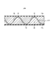
- FIG. 1 is a diagram schematically showing a cross section of a panel structure according to the first embodiment.
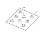
- FIG. 2 is a diagram schematically showing a core member according to the first embodiment;
- FIG. 3 is a diagram schematically showing a cross section of the panel structure according to the second embodiment.
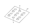
- FIG. 4 is a diagram schematically showing a core member according to the second embodiment.
- FIG. 5 is a diagram schematically showing a cross section of a panel structure according to the third embodiment.
- FIG. 6 is a diagram schematically showing a core member according to the third embodiment.
- FIG. 7 is a diagram schematically showing a cross section of the panel structure according to the fourth embodiment.
- FIG. 8 is a diagram schematically showing a cross section of a panel structure according to the fifth embodiment.
- FIG. 1 is a diagram schematically showing a cross section of a panel structure according to the first embodiment.
- FIG. 2 is a diagram schematically showing a core member according to the first embodiment;
- FIG. 3 is a
- FIG. 9 is a diagram schematically showing a cross section of a panel structure according to the sixth embodiment.
- FIG. 10 is a diagram schematically showing a cross section of a panel structure according to a modification of the sixth embodiment.
- FIG. 11 is a diagram schematically showing a cross section of a panel structure according to the seventh embodiment.
- FIG. 12 is a diagram schematically showing a cross section of a panel structure according to a modification of the seventh embodiment;
- FIG. 13 is a diagram schematically showing a cross section of the panel structure according to the eighth embodiment.
- FIG. 14 is a diagram schematically showing a cross section of a panel structure according to the ninth embodiment.
- FIG. 15 is a diagram schematically showing a cross section of the panel structure according to the tenth embodiment.
- FIG. 16 is a diagram schematically showing a cross section of a panel structure according to the eleventh embodiment.
- FIG. 1 is a diagram schematically showing a cross section of a panel structure according to the first embodiment.
- FIG. 2 is a diagram schematically showing a core member according to the first embodiment;
- the panel structure of the present disclosure can be applied, for example, to automobiles, trains, other mobility products, buildings, and the like.
- the panel structure 10 includes a core member 12, a faceplate 14, and a fused portion 16.
- the core member 12 has thermoplasticity.
- the core member 12 is made of thermoplastic resin and formed in a plate shape.
- thermoplastic resins include, but are not limited to, polyamide resins, polypropylene resins, ABS resins, polyetheretherketones, polyetherketoneketones, and polyphenylene sulfides.
- the thermoplastic resin is preferably thermoplastic reinforced fiber plastic (FRP: Fiber Reinforced Plastics) containing reinforcing fibers.
- the reinforced fiber plastics are preferably, for example, glass fiber reinforced plastics (GFRP) and carbon fiber reinforced plastics (CFRP). Reinforced fiber plastics are not limited to these.
- the core member 12 has a plurality of protrusions 18 on one surface.
- the core member 12 has a concave portion 20 at a position corresponding to the convex portion 18 on the other surface. As shown in FIG. 2, a plurality of protrusions 18 are formed on one surface of the core member 12 .
- the core member 12 is preferably made of a material with low thermal conductivity in order to improve the heat insulating properties of the panel structure 10 .
- the core member 12 is made of, for example, carbon fiber reinforced plastic with low thermal conductivity, glass fiber reinforced plastic, a mixture of glass fiber reinforced plastic and carbon fiber reinforced plastic, short fiber carbon fiber reinforced plastic, or the like. should be formed.
- the faceplate 14 is arranged on one side of the core member 12 .
- the face plate 14 is arranged on the protrusion 18 on one surface of the core member 12 .
- Faceplate 14 is thermoplastic.
- the face plate 14 is made of thermoplastic resin and formed into a plate shape. Examples of thermoplastic resins include, but are not limited to, polyamide resins, polypropylene resins, ABS resins, polyetheretherketones, polyetherketoneketones, and polyphenylene sulfides.
- the thermoplastic resin is preferably thermoplastic reinforced fiber plastic containing reinforcing fibers.
- the reinforced fiber plastics are preferably glass fiber reinforced plastics and carbon fiber reinforced plastics, for example. Reinforced fiber plastics are not limited to these.
- the core member 12 and the faceplate 14 may be made of the same material or may be made of different materials.
- the core member 12 may be formed using a normal thermoplastic resin, and the face plate 14 may be formed using a reinforced fiber plastic having thermoplasticity.
- the core member 12 may be made of reinforced fiber plastic having thermoplasticity, and the face plate 14 may be made of ordinary thermoplastic resin.
- the core member 12 and the face plate 14 may be made of different thermoplastic resins.
- the core member 12 may be made of polyamide resin and the face plate 14 may be made of polypropylene resin.
- the fused portion 16 joins the core member 12 and the faceplate 14 .
- the fused portion 16 is formed between the top of the projection 18 and one surface of the faceplate 14 .
- the fused portion 16 is selectively formed between the tops of the plurality of protrusions 18 and one surface of the faceplate 14 .
- the fused portions 16 are selectively formed between the tops of the plurality of protrusions 18 and one surface of the faceplate 14 according to, for example, the rigidity and impact resistance properties required of the panel structure 10. be.
- the fused portion 16 can be formed by heating and melting the top of the convex portion 18 and the joining portion of the faceplate 14, and then placing and cooling the faceplate 14. FIG. Examples of heating include, but are not limited to, using a heat source such as a heater and heating wire, ultrasonic vibration, electromagnetic induction by a magnetic field, and laser.
- the core member 12 and the faceplate 14 are joined together by the fusion-bonded portion 16, thereby improving the reliability of joining the core member 12 and the faceplate 14. be able to.
- FIG. 3 is a diagram schematically showing a cross section of the panel structure according to the second embodiment.
- FIG. 4 is a diagram schematically showing a core member according to the second embodiment.
- the panel structure 10A includes a core member 12A, a faceplate 14a, a faceplate 14b, and a fused portion 16.
- the panel structure 10A has faceplates on both sides of the core member 12A.
- the core member 12A differs from the core member 12 shown in FIG. 1 in that it has protrusions 18 on both sides. 12 A of core members have the recessed part 20 in the position corresponding to the convex part 18 in both surfaces. As shown in FIG. 3, the core member 12A has a plurality of protrusions 18 and a plurality of recesses 20 on both sides.
- the face plate 14a is arranged on one side of the core member 12A.
- the face plate 14a is arranged on the protrusion 18 on one surface of the core member 12A.
- the faceplate 14b is arranged on the other surface of the core member 12A.
- the faceplate 14b is arranged on the other surface of the core member 12A.
- the face plate 14b is arranged on the convex portion 18 on the other surface of the core member 12A.
- the panel structure 10A has an air layer between the core member 12A and the faceplate 14a.
- the panel structure 10A has an air layer between the core member 12A and the faceplate 14b.
- the fused portion 16 joins the core member 12A and the faceplate 14a on one surface of the core member 12A.
- the fused portion 16 is formed between the top of the projection 18 and one surface of the face plate 14a.
- the fused portion 16 is selectively formed between the tops of the plurality of protrusions 18 and one surface of the face plate 14a.
- the fused portions 16 are selectively formed between the tops of the plurality of projections 18 and one surface of the face plate 14a, depending on, for example, the rigidity and impact resistance properties required of the panel structure 10A. be.
- the fusion-bonded portion 16 can be formed by heating and melting the joining portion between the top of the convex portion 18 and the faceplate 14a, and then placing and cooling the faceplate 14a.
- the fused portion 16 joins the core member 12A and the face plate 14b on the other surface of the core member 12A.
- the fused portion 16 is formed between the top of the projection 18 and one surface of the face plate 14b.
- the fused portion 16 is selectively formed between the tops of the plurality of protrusions 18 and one surface of the face plate 14b.
- the fused portions 16 are selectively formed between the tops of the plurality of protrusions 18 and one surface of the face plate 14b, depending on, for example, the rigidity and impact resistance properties required of the panel structure 10A. be.
- the fusion-bonded portion 16 can be formed by heating and melting the joining portion between the top of the convex portion 18 and the face plate 14b, and then placing and cooling the face plate 14b.
- the core member 12A and the faceplates 14a and 14b are joined by the fused portions 16. As shown in FIG. Thereby, the second embodiment can improve the reliability of bonding between the core member 12A and the faceplates 14a and 14b.
- the core member 12A and the faceplates 14a and 14b are joined by the fusion-bonded portions 16, thereby eliminating the need for joining members such as bolts and increasing the weight. can be suppressed.
- FIG. 5 is a diagram schematically showing a cross section of a panel structure according to the third embodiment.
- FIG. 6 is a diagram schematically showing a core member according to the third embodiment.
- the panel structure 10B includes a core member 12B, a faceplate 14a, a faceplate 14b, and a fused portion 16.
- the core member 12B differs from the core member 12 shown in FIG. 1 in that it has corrugated portions 22 . As shown in FIG. 6, the core member 12B is formed in a corrugated shape and has a plurality of corrugated portions 22 . A corrugated shape may also be referred to as a corrugated shape. The corrugations 22 are one type of the protrusions 18 and the recesses 20 .
- the panel structure 10B has an air layer between the core member 12B and the faceplate 14a.
- the panel structure 10B has an air layer between the core member 12B and the faceplate 14b.
- the fused portion 16 joins the core member 12B and the faceplate 14a on one surface of the core member 12B.
- the fused portion 16 is formed between the crest of the corrugated portion 22 and one surface of the faceplate 14a.
- the fused portion 16 is selectively formed between the crests of the plurality of wave portions 22 and one surface of the faceplate 14a.
- the fused portions 16 are selectively formed between the crests of the plurality of wave portions 22 and one surface of the faceplate 14a according to, for example, the rigidity and impact resistance properties required of the panel structure 10B. be.
- the fused portion 16 may be formed by heating and melting the joints of the crests of the corrugations 22 and the faceplate 14a, and then placing and cooling the faceplate 14a.
- the fused portion 16 joins the core member 12B and the face plate 14b on the other surface of the core member 12B.
- the fused portion 16 is formed between the crest of the corrugated portion 22 and one surface of the face plate 14b.
- the fused portion 16 is selectively formed between the crests of the plurality of wave portions 22 and one surface of the faceplate 14b.
- the fused portions 16 are selectively formed between the crests of the plurality of wave portions 22 and one surface of the face plate 14b, depending on, for example, the rigidity and impact resistance properties required of the panel structure 10B. be.
- the fused portion 16 may be formed by heating and melting the joints of the crests of the corrugations 22 and the faceplate 14b, and then placing and cooling the faceplate 14a.
- the core member 12B and the faceplates 14a and 14b are joined by the fused portions 16. As shown in FIG. Thereby, the third embodiment can improve the reliability of bonding between the core member 12B and the faceplates 14a and 14b.
- the core member 12B and the faceplates 14a and 14b are joined by the fusion parts 16, thereby eliminating the need for joining members such as bolts and increasing the weight. can be suppressed.
- FIG. 7 is a diagram schematically showing a cross section of the panel structure according to the fourth embodiment.
- a panel structure 10C according to the fourth embodiment includes a core member 12B, a face plate 14a, a face plate 14b, a fused portion 16, and a metal thin film 24.
- the panel structure 10C differs from the panel structure 10B shown in FIG. 5 in that the metal thin film 24 is provided.
- the metal thin film 24 is formed on one surface of the face plate 14b in the example shown in FIG. 7, it is not limited to this.
- the metal thin film 24 can be formed on at least one surface of at least one of the faceplates 14a and 14b.
- the metal thin film 24 can be formed, for example, by evaporating metal or plating the face plate 14b.
- Metal film 24 may be any metal.
- Metal thin film 24 may be formed by other methods.
- a panel structure 10C according to the fourth embodiment has a metal thin film 24 on at least one surface of at least one of the faceplate 14a and the faceplate 14b. Thereby, the fourth embodiment can reduce the radiant heat generated in the panel structure 10C.
- FIG. 8 is a diagram schematically showing a cross section of a panel structure according to the fifth embodiment.
- a panel structure 10D includes a core member 12Ba, a core member 12Bb, a face plate 14a, a face plate 14b, a face plate 14c, a fused portion 16, Prepare.
- the panel structure 10D differs from the panel structure 10B shown in FIG. 5 in that it includes a plurality of core members.
- the fused portion 16 joins the core member 12Ba and the faceplate 14a on one surface of the core member 12Ba.
- the fused portion 16 joins the core member 12Ba and the face plate 14c on the other surface of the core member 12Ba.
- the fused portion 16 joins the core member 12Bb and the face plate 14c on one surface of the core member 12Bb.
- the fused portion 16 joins the core member 12Bb and the face plate 14b on the other surface of the core member 12Bb.
- the core member 12Ba and the core member 12Bb are each coupled to a single common face plate 14c, but the present disclosure is not limited to this.
- the face plate 14c may have a structure in which two face plates are joined or fused, one to which the core member 12Ba is coupled and the other to which the core member 12Bb is coupled. good.
- the core member 12Ba and the core member 12Bb may be formed so that their tops are aligned, or their tops may be deviated.
- the core member 12Ba and the core member 12Bb may have different shapes.
- the panel structure 10D has an air layer between the core member 12Ba and the faceplate 14a.
- the panel structure 10D has an air layer between the core member 12Ba and the faceplate 14c.
- the panel structure 10D has an air layer between the core member 12Bb and the faceplate 14c.
- the panel structure 10D has an air layer between the core member 12Bb and the faceplate 14b. That is, panel structure 10D has more air layers than panel structure 10B shown in FIG.
- the panel structure 10D according to the fifth embodiment can increase the volume of the air layer by using a plurality of core members such as the core member 12Ba and the core member 12Bb.
- 5th Embodiment can improve heat insulation.
- 5th Embodiment can improve sound insulation.
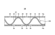
- FIG. 9 is a diagram schematically showing a cross section of a panel structure according to the sixth embodiment.
- the panel structure 10E includes a core member 12B, a faceplate 14a, a faceplate 14b, a fused portion 16, and a filling member 26.
- the panel structure 10E differs from the panel structure 10B shown in FIG. 5 in that a filling member 26 is provided.
- the filling member 26 is arranged between the core member 12B and the faceplates 14a and 14b.
- a filler member 26 may be selectively positioned between core member 12B and faceplates 14a and 14b.
- the filling member 26 may be formed of a foam member having at least one of heat insulation and sound absorption, such as urethane foam. It should be noted that the filling member 26 is not limited to a foam member, and may be formed of another member having at least one of heat insulation and sound absorption properties.
- the filling member 26 is formed into a predetermined shape to bond the core member 12B and the faceplates 14a and 14b together. Place in the space between.
- the filling member 26 is melted by the heat generated when the core member 12B and the faceplates 14a and 14b are heat-sealed, and adheres to the core member 12B and the faceplates 14a and 14b. Thereby, the filling member 26 is arranged between the core member 12B and the faceplates 14a and 14b.
- a panel structure 10E according to the sixth embodiment has a filling member 26 between the core member 12B and the faceplates 14a and 14b.
- 6th Embodiment can improve heat insulation.
- the sixth embodiment can also improve sound insulation.
- FIG. 10 is a diagram schematically showing a cross section of a panel structure according to a modification of the sixth embodiment.
- a panel structure 10F includes a core member 12Ba, a core member 12Bb, a face plate 14a, a face plate 14b, a face plate 14c, and a fusion-bonded portion. 16 and a filler member 26 .
- the panel structure 10F differs from the panel structure 10D shown in FIG. 8 in that a filling member 26 is provided.
- the core member 12Ba and the core member 12Bb are each coupled to a single common face plate 14c, but the present disclosure is not limited to this.
- the faceplate 14c may have a structure in which two faceplates, one to which the core member 12Ba is coupled and the other to which the core member 12Bb are coupled, are joined or fused. good.
- the panel structure 10F receives heat or sound from a heat source or sound source (not shown) from the core member 12Ba side.
- the filling member 26 is preferably formed between the core member 12Ba and the faceplates 14a and 14c. That is, when there are a plurality of core members, the filling member 26 is preferably formed on the heat source side or the sound source side.
- the panel structure 10F according to the modification of the sixth embodiment forms a foam member between the core member 12Ba and the faceplates 14a and 14c to insulate from the side that directly receives heat or sound. or can be sound insulated.
- the modification of 6th Embodiment can improve heat insulation.
- the modification of the sixth embodiment can improve sound insulation.
- FIG. 11 is a diagram schematically showing a cross section of a panel structure according to the seventh embodiment.
- the panel structure 10G includes a core member 12B, a faceplate 14a, a faceplate 14b, a fused portion 16, and a flow path 28.
- the panel structure 10G differs from the panel structure 10B shown in FIG.
- the flow path 28 is formed between the core member 12B and the faceplates 14a and 14b.
- Channels 28 allow fluid to flow between core member 12B and faceplates 14a and 14b.
- Fluids are, for example, gases and liquids.
- the fluids are, for example, air and water, but are not limited thereto.
- Channel 28 cools panel structure 10G by flowing fluid between core member 12B and faceplates 14a and 14b.
- the flow path 28 cools or heats the outside air, such as the interior of the vehicle, according to the temperature of the fluid flowing therein.
- the object to be temperature-controlled is cooled or heated according to the correlation between the temperature of the fluid flowing through the flow path 28 and the temperature of the object to be temperature-controlled.
- the temperature of the temperature control object may be measured, and the temperature of the fluid may be determined by feedback control based on the temperature measurement result.
- the temperature control target by controlling the temperature of the fluid according to the temperature of the temperature control target, the temperature control target can be appropriately cooled or heated.
- the sound insulation may be improved by flowing the fluid through the flow path 28.
- the sound propagation characteristics change depending on whether the fluid is gas or liquid. Sound propagation characteristics also change according to physical properties such as fluid viscosity. That is, by selecting the state and physical characteristics of the fluid flowing through the flow path 28, it is possible to improve the sound insulation against the sound received by the panel structure 10G from a sound source (not shown).
- the frequency band of the sound to be insulated is known in advance, the sound can be effectively attenuated by selecting a fluid that can attenuate the sound in that frequency band and flowing it through the flow path 28. be able to. That is, in the seventh embodiment, sound insulation can be improved by selecting physical properties such as the state and viscosity of the fluid flowing through the flow path 28 according to the sound received by the panel structure 10G.
- the panel structure 10G according to the seventh embodiment can be cooled by flowing a fluid between the core member 12B and the faceplates 14a and 14b.
- 7th Embodiment can improve heat insulation.
- the seventh embodiment by flowing a fluid having a temperature lower than the heat of the outside through the flow path 28, the outside air such as the inside of the vehicle can be cooled.
- the seventh embodiment can heat the outside air, such as the inside of a car, by flowing a fluid having a higher temperature than the outside heat through the flow path 28 .
- FIG. 12 is a diagram schematically showing a cross section of a panel structure according to a modification of the seventh embodiment
- the panel structure 10H according to the modified example of the seventh embodiment includes a core member 12Ba, a core member 12Bb, a face plate 14a, a face plate 14b, a face plate 14c, and a fused portion. 16 and a channel 28 .
- Panel structure 10H differs from panel structure 10D shown in FIG.
- the panel structure 10H receives heat from a heat source (not shown) from the core member 12Ba side.
- the channel 28 is preferably formed between the core member 12Ba and the faceplates 14a and 14c. That is, when there are a plurality of core members, the flow path 28 is preferably formed on the heat source side.
- the panel structure 10H according to the modification of the seventh embodiment can cool the side receiving heat directly by flowing a fluid between the core member 12Ba and the faceplates 14a and 14c. . Thereby, the modification of the seventh embodiment can improve the heat insulation.
- FIG. 13 is a diagram schematically showing a cross section of the panel structure according to the eighth embodiment.
- the panel structure 10I includes a core member 12B, a faceplate 14a, a faceplate 14b, a fused portion 16, and a hole portion 30. Panel structure 10I differs from panel structure 10B shown in FIG.
- the holes 30 can be formed in the core member 12B, the faceplate 14a, and the faceplate 14b. Holes 30 may be formed, for example, in at least one of core member 12B, faceplate 14a, and faceplate 14b.
- the panel structure 10I has the holes 30 to absorb the sound generated by the sound resonance effect.
- the panel structure H has, for example, the holes 30 to reflect sound inside and cancel the sound.
- the number of holes 30 and the positions where the holes 30 are formed can be arbitrarily changed according to the design.
- the number of holes 30 and the positions where the holes 30 are formed can be arbitrarily changed according to the volume of sound to be absorbed, the frequency of sound, the range of sound, and the like.
- holes 30 may be optionally formed in the plurality of core members and the faceplate.
- the eighth embodiment By forming the holes 30 in the panel structure 10I according to the eighth embodiment, the sound generated from the panel structure 10I can be absorbed by the sound resonance effect. As a result, the eighth embodiment can prevent noise generated in one of the faceplates 14a and 14b from being transmitted to the other.
- the core member 12B, the faceplate 14a, and the faceplate 14b may be made of porous resin or non-woven carbon fiber-containing resin.
- the resin is preferably a porous resin or a carbon fiber reinforced plastic containing non-woven carbon fibers.
- the core member 12B, the face plate 14a, and the face plate 14b, which are made of porous resin or the like, have minute holes. Therefore, by forming the core member 12B, the face plate 14a, and the face plate 14b from a porous resin or the like, sound can be resonated in the same manner as in the case where the holes 30 are formed. Incidentally, in the modified example of the eighth embodiment, the holes 30 do not necessarily have to be formed.
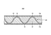
- FIG. 14 is a diagram schematically showing a cross section of a panel structure according to the ninth embodiment.
- a panel structure 10J according to the ninth embodiment includes a core member 12B, a faceplate 14a, a faceplate 14b, a fusion-bonded portion 16, and a sound absorbing member 32.
- the panel structure 10J differs from the panel structure 10B shown in FIG. 5 in that a sound absorbing member 32 is provided.
- the sound absorbing member 32 is arranged between the core member 12B and the faceplates 14a and 14b. Sound absorbing members 32 may be selectively disposed between core member 12B and faceplates 14a and 14b.
- the sound absorbing member 32 may be formed of any member that has a sound absorbing effect, for example.
- a panel structure 10J according to the ninth embodiment has a sound absorbing member 32 between the core member 12B and the faceplates 14a and 14b. Thereby, 9th Embodiment can improve sound insulation.
- FIG. 15 is a diagram schematically showing a cross section of the panel structure according to the tenth embodiment.
- the panel structure 10K includes a core member 12B, a faceplate 14a, a faceplate 14b, an adhesive portion 34, and a filling member 26.
- Panel structure 10K differs from panel structure 10B shown in FIG.
- the adhesive portion 34 joins the core member 12B and the faceplate 14a on one surface of the core member 12B.
- the bonding portion 34 is formed between the crest of the wave portion 22 and one surface of the faceplate 14a.
- the bonding portion 34 is selectively formed between the crests of the plurality of wave portions 22 and one surface of the faceplate 14a.
- the bonding portion 34 is selectively formed between the crests of the plurality of wave portions 22 and one surface of the faceplate 14a, depending on, for example, the rigidity and impact resistance properties required for the panel structure 10K.
- the bonding portion 34 can be formed, for example, by bonding the corrugated portion 22 and the face plate 14a using an adhesive for resin and then drying. A well-known adhesive for resin may be used.
- the adhesive part 34 joins the core member 12B and the face plate 14b on the other surface of the core member 12B.
- the bonding portion 34 is formed between the crest of the wave portion 22 and one surface of the faceplate 14b.
- the bonding portion 34 is selectively formed between the crests of the plurality of wave portions 22 and one surface of the faceplate 14b.
- the bonding portion 34 is selectively formed between the crests of the plurality of wave portions 22 and one surface of the face plate 14b, depending on, for example, the rigidity and impact resistance properties required for the panel structure 10K. .
- the bonding portion 34 can be formed by bonding the corrugated portion 22 and the face plate 14b with an adhesive for resin and then drying.
- the filling member 26 is formed into a predetermined shape so that the core member 12B and the faceplates 14a and 14b are bonded together. placed in the space between After the core member 12B, the faceplate 14a, and the faceplate 14b are bonded together at the bonding portion 34, the filling member 26 is melted by heating with a heat source (not shown), and the core member 12B, the faceplate 14a, and the faceplate 14a are melted. It sticks to the plate 14b. Thereby, the filling member 26 is arranged between the core member 12B and the faceplates 14a and 14b.
- the panel structure 10K according to the tenth embodiment has a filling member 26 between the core member 12B joined by the adhesive portion 34 and the faceplates 14a and 14b.
- the tenth embodiment can improve the heat insulating properties of the panel structure 10K that is bonded with an adhesive.
- a channel 28 may be formed through which the fluid flows.
- FIG. 16 is a diagram schematically showing a cross section of a panel structure according to the eleventh embodiment.
- the panel structure 10L includes a core member 12B, a faceplate 14a, a faceplate 14b, an adhesive portion 34, and a sound absorbing member 32.
- the panel structure 10L differs from the panel structure 10K shown in FIG. 15 in that a sound absorbing member 32 is provided instead of the filling member 26.
- the sound absorbing member 32 is arranged between the core member 12B joined by the adhesive portion 34 and the faceplates 14a and 14b. Sound absorbing members 32 may be selectively disposed between core member 12B and faceplates 14a and 14b.
- the sound absorbing member 32 may be formed of any member that has a sound absorbing effect, for example.
- the panel structure 10L according to the eleventh embodiment has a sound absorbing member 32 between the core member 12B joined by the adhesive portion 34 and the faceplates 14a and 14b. Thereby, 11th Embodiment can improve sound insulation.
- At least one of the core member 14B and the faceplate 14a and the faceplate 14b instead of the sound absorbing member 32 is provided in FIG.
- the holes 30 shown may be formed.
- each core member and each face plate shown in the first to ninth embodiments may be bonded with an adhesive for resin.
- the panel structure of the first aspect includes a plate-shaped core member 12 having thermoplasticity and having a plurality of protrusions 18 on at least one surface, and a thermoplastic plate disposed on the plurality of protrusions 18.
- a faceplate 14 having a shape; a fusion portion 16 selectively formed between a core member 12 and a plurality of protrusions 18 to couple the core member 12 and the faceplate 14 together;
- the core member 12 and the face plate 14 are joined together by the fused portion 16 formed by thermal fusion.
- the panel structure of the first aspect can improve the reliability of bonding between the core member 12 and the face plate 14 .
- the core member 12 and the face plate 14 are joined by the fusion-bonded portion 16, thereby eliminating the need for joining members such as bolts, thereby suppressing an increase in weight. .
- the protrusions 18 are formed on both sides of the core member 12 .
- the panel structure of the second aspect can improve the reliability of bonding between the core member 12 and the faceplate 14 on both sides of the core member 12 .
- the convex portion 18 is a continuous wave portion 22 formed on the surface of the core member 12 .
- the panel structure of the third aspect can improve the reliability of bonding between the core member 12 and the faceplate 14 when the core member 12 has a wavy shape.
- the panel structure of the fourth aspect comprises a metal thin film formed on at least one surface of the faceplate 14 . Thereby, the panel structure of the fourth aspect can reduce radiant heat.
- the panel structure of the fifth aspect comprises a filling member 26 arranged in the space between the core member 12 and the faceplate 14. Thereby, the panel structure of the fifth aspect can improve heat insulation. Moreover, the panel structure of the fifth aspect can improve sound insulation.
- the panel structure of the sixth aspect includes multiple core members 12 . Thereby, the panel structure of the sixth aspect can increase the number of internal air layers. As a result, the panel structure of the sixth aspect can improve heat insulation. Moreover, the panel structure of the sixth aspect can improve sound insulation.
- the panel structure of the seventh aspect comprises a channel 28 through which fluid flows between the core member 12 and the faceplate 14 .
- the panel structure of the seventh aspect can cool the inside.
- the panel structure of the seventh aspect can improve heat insulation.
- the panel structure of the seventh aspect can cool or heat the temperature of the interior of a vehicle by appropriately adjusting the temperature of the fluid.
- the fluid is liquid or gas.
- the panel structure of the eighth aspect can easily cool the inside using any fluid.
- the panel structure of the eighth aspect can easily improve heat insulation.
- the panel structure of the eighth aspect can use any fluid to cool or heat the temperature of the interior of a car or the like.
- the panel structure of the ninth aspect has holes 30 selectively formed in at least one of the core member 12 and the face plate 14 . Thereby, the panel structure of the ninth aspect can resonate sound inside. As a result, the panel structure of the ninth aspect can prevent the noise generated in one face plate 14 from being transmitted to the other face plate 14, so that the sound insulation can be improved.
- the face plate 14 is made of porous resin or non-woven carbon fiber-containing resin.
- the panel structure of the tenth aspect can internally resonate sound.
- the panel structure of the tenth aspect can improve sound insulation.
Landscapes
- Engineering & Computer Science (AREA)
- Physics & Mathematics (AREA)
- Acoustics & Sound (AREA)
- Multimedia (AREA)
- Textile Engineering (AREA)
- Laminated Bodies (AREA)
Abstract
パネル構造体は、熱可塑性を有し、少なくとも一方の面に複数の凸部を有する板状のコア部材と、複数の凸部に配置され、熱可塑性を有する板状のフェイスプレートと、コア部材と、複数の凸部との間に選択的に形成され、コア部材と、フェイスプレートとを結合する融着部と、を備える。
Description
本開示は、パネル構造体に関する。
自動車、電車、および他のモビリティ製品などの車体には、剛性の高いサンドイッチパネルが用いられている(例えば、特許文献1)。
通常、サンドイッチパネルは、2枚のフェイスプレートの間にコア部材を配置し、フェイスプレートと、コア部材とを接着剤で接合することで構成されている。しかしながら、接着剤を用いた接合では、フェイスプレートと、コア部材との接着不良が生じる可能性がある。接着強度を強くするために、もしくは接着の信頼性を向上させるためにボルトなどを用いてフェイスプレートと、コア部材とを接合する場合、フェイスプレートと、コア部材とに接合用の孔をあける必要があるため、サンドイッチパネルの機械強度が低下する可能性があり、材料が繊維強化樹脂である場合に特に顕著である。また、フェイスプレートと、コア部材とをボルトなどで結合することで重量が増加し、かつサンドイッチパネルの製造工程が煩雑となる可能性もある。
本開示は、フェイスプレートと、コア部材との接合の信頼性を向上させることができるパネル構造体を提供することを目的とする。
本開示の一態様に係るパネル構造体は、熱可塑性を有し、少なくとも一方の面に複数の凸部を有する板状のコア部材と、複数の前記凸部に配置され、熱可塑性を有する板状のフェイスプレートと、前記コア部材と、複数の前記凸部との間に選択的に形成され、前記コア部材と、前記コア部材とを結合する融着部と、を備える。
本開示によれば、フェイスプレートと、コア部材との接合の信頼性を向上させることができる。
以下、添付図面を参照して、本発明に係る実施形態を詳細に説明する。なお、この実施形態により本発明が限定されるものではなく、また、実施形態が複数ある場合には、各実施形態を組み合わせて構成するものも含む。また、以下の実施形態において、同一の部位には同一の符号を付することにより重複する説明を省略する。
[第1実施形態]
図1と、図2とを用いて、第1実施形態に係るパネル構造体の構成について説明する。図1は、第1実施形態に係るパネル構造体の断面を模式的に示す図である。図2は、第1実施形態に係るコア部材を模式的に示す図である。本開示のパネル構造体は、例えば、自動車、電車、その他のモビリティ製品、および建築物などに適用され得る。
図1と、図2とを用いて、第1実施形態に係るパネル構造体の構成について説明する。図1は、第1実施形態に係るパネル構造体の断面を模式的に示す図である。図2は、第1実施形態に係るコア部材を模式的に示す図である。本開示のパネル構造体は、例えば、自動車、電車、その他のモビリティ製品、および建築物などに適用され得る。
図1に示すように、パネル構造体10は、コア部材12と、フェイスプレート14と、融着部16とを、備える。
コア部材12は、熱可塑性を有する。コア部材12は、熱可塑性樹脂で板状に形成されている。熱可塑性樹脂は、ポリアミド樹脂、ポリプロピレン樹脂、ABS樹脂、ポリエーテルエーテルケトン、ポリエーテルケトンケトン、およびポリフェニレンサルファイドなどが例示されるが、これらに限定されない。熱可塑性樹脂は、強化繊維を含んだ熱可塑性の強化繊維プラスチック(FRP:Fiber Reinforced Plastics)であることが好ましい。強化繊維プラスチックは、例えば、ガラス繊維強化プラスチック(GFRP:Glass Fiber Reinforced Plastics)、および炭素繊維強化プラスチック(CFRP:Carbon Fiber Reinforced Plastics)であることが好ましい。強化繊維プラスチックは、これらに限定されない。コア部材12は、一方の面に複数の凸部18を有する。コア部材12は、他方の面において、凸部18に対応する位置に凹部20を有する。図2に示すように、コア部材12の一方の面には複数の凸部18が形成されている。
コア部材12は、例えば、パネル構造体10の断熱性を向上させるために、熱伝導率の低い材料で形成することが好ましい。この場合、コア部材12は、例えば、熱伝導率の低い炭素繊維強化プラスチック、ガラス繊維強化プラスチック、ガラス繊維強化プラスチックと炭素繊維強化プラスチックとの混合剤、短繊維の炭素繊維強化プラスチックなどを用いて形成すればよい。
フェイスプレート14は、コア部材12の一方の面に配置される。フェイスプレート14は、コア部材12の一方の面の凸部18上に配置される。フェイスプレート14は、熱可塑性を有する。フェイスプレート14は、熱可塑性樹脂で板状に形成されている。熱可塑性樹脂は、ポリアミド樹脂、ポリプロピレン樹脂、ABS樹脂、ポリエーテルエーテルケトン、ポリエーテルケトンケトン、およびポリフェニレンサルファイドなどが例示されるが、これらに限定されない。熱可塑性樹脂は、強化繊維を含んだ熱可塑性の強化繊維プラスチックであることが好ましい。強化繊維プラスチックは、例えば、ガラス繊維強化プラスチック、および炭素繊維強化プラスチックであることが好ましい。強化繊維プラスチックはこれらに限定されない。コア部材12と、フェイスプレート14とは、同じ材料で形成されてもよいし、異なる材料で形成されてもよい。例えば、本実施形態では、コア部材12を通常の熱可塑性樹脂で用いて形成し、フェイスプレート14を、熱可塑性を有する強化繊維プラスチックで形成してもよい。また、コア部材12を、熱可塑性を有する強化繊維プラスチックで形成し、フェイスプレート14を、通常の熱可塑性樹脂で形成してもよい。また、コア部材12と、フェイスプレート14とは、種類の異なる熱可塑性樹脂で形成されてもよい。例えば、本実施形態では、コア部材12をポリアミド樹脂で形成し、フェイスプレート14をポリプロピレン樹脂で形成してもよい。
融着部16は、コア部材12と、フェイスプレート14とを結合する。融着部16は、凸部18の頂部と、フェイスプレート14の一方の面との間に形成されている。融着部16は、複数の凸部18の頂部と、フェイスプレート14の一方の面との間に選択的に形成されている。融着部16は、例えば、パネル構造体10に求められる剛性および耐衝撃性特性に応じて、複数の凸部18の頂部と、フェイスプレート14の一方の面との間に選択的に形成される。融着部16は、凸部18の頂部およびフェイスプレート14の接合得箇所を加熱して溶融させた後、フェイスプレート14を配置して冷却することで形成され得る。加熱は、例えば、ヒーターおよび電熱線などの熱源、超音波振動、磁場による電磁誘導、およびレーザーを用いることが挙げられるが、これらの方法に限定されない。
第1実施形態に係るパネル構造体10は、コア部材12と、フェイスプレート14とは、融着部16により結合することで、コア部材12と、フェイスプレート14との接合の信頼性を向上させることができる。
[第2実施形態]
図3と、図4とを用いて、第2実施形態に係るパネル構造体の構成について説明する。図3は、第2実施形態に係るパネル構造体の断面を模式的に示す図である。図4は、第2実施形態に係るコア部材を模式的に示す図である。
図3と、図4とを用いて、第2実施形態に係るパネル構造体の構成について説明する。図3は、第2実施形態に係るパネル構造体の断面を模式的に示す図である。図4は、第2実施形態に係るコア部材を模式的に示す図である。
図3に示すように、パネル構造体10Aは、コア部材12Aと、フェイスプレート14aと、フェイスプレート14bと、融着部16と、を備える。パネル構造体10Aは、コア部材12Aの両面にフェイスプレートを備えている。
コア部材12Aは、両面に凸部18を有する点で、図1に示すコア部材12と異なる。コア部材12Aは、両面において、凸部18に対応する位置に凹部20を有する。図3に示すように、コア部材12Aは、両面において、複数の凸部18および複数の凹部20を有する。
フェイスプレート14aは、コア部材12Aの一方の面に配置される。フェイスプレート14aは、コア部材12Aの一方の面の凸部18上に配置される。フェイスプレート14bは、コア部材12Aの他方の面に配置される。フェイスプレート14bは、コア部材12Aの他方の面に配置される。フェイスプレート14bは、コア部材12Aの他方の面の凸部18上に配置される。パネル構造体10Aは、コア部材12Aと、フェイスプレート14aとの間に空気層を有する。パネル構造体10Aは、コア部材12Aと、フェイスプレート14bとの間に空気層を有する。
融着部16は、コア部材12Aの一方の面において、コア部材12Aと、フェイスプレート14aとを結合する。融着部16は、凸部18の頂部と、フェイスプレート14aの一方の面との間に形成されている。融着部16は、複数の凸部18の頂部と、フェイスプレート14aの一方の面との間に選択的に形成されている。融着部16は、例えば、パネル構造体10Aに求められる剛性および耐衝撃性特性に応じて、複数の凸部18の頂部と、フェイスプレート14aの一方の面との間に選択的に形成される。融着部16は、凸部18の頂部およびフェイスプレート14aの接合箇所を加熱して溶融させた後、フェイスプレート14aを配置して冷却することで形成され得る。
融着部16は、コア部材12Aの他方の面において、コア部材12Aと、フェイスプレート14bとを結合する。融着部16は、凸部18の頂部と、フェイスプレート14bの一方の面との間に形成されている。融着部16は、複数の凸部18の頂部と、フェイスプレート14bの一方の面との間に選択的に形成されている。融着部16は、例えば、パネル構造体10Aに求められる剛性および耐衝撃性特性に応じて、複数の凸部18の頂部と、フェイスプレート14bの一方の面との間に選択的に形成される。融着部16は、凸部18の頂部およびフェイスプレート14bの接合箇所を加熱して溶融させた後、フェイスプレート14bを配置して冷却することで形成され得る。
第2実施形態に係るパネル構造体10Aは、コア部材12Aと、フェイスプレート14aおよびフェイスプレート14bとは、融着部16により結合する。これにより、第2実施形態は、コア部材12Aと、フェイスプレート14aおよびフェイスプレート14bとの接合の信頼性を向上させることができる。また、第2実施形態に係るパネル構造体10Aは、コア部材12Aと、フェイスプレート14aおよびフェイスプレート14bとは、融着部16により結合することで、ボルトなどの接合部材が不要となり、重量増加を抑制することができる。
[第3実施形態]
図5と、図6とを用いて、第3実施形態に係るパネル構造体の構成について説明する。図5は、第3実施形態に係るパネル構造体の断面を模式的に示す図である。図6は、第3実施形態に係るコア部材を模式的に示す図である。
図5と、図6とを用いて、第3実施形態に係るパネル構造体の構成について説明する。図5は、第3実施形態に係るパネル構造体の断面を模式的に示す図である。図6は、第3実施形態に係るコア部材を模式的に示す図である。
図5に示すように、パネル構造体10Bは、コア部材12Bと、フェイスプレート14aと、フェイスプレート14bと、融着部16と、を備える。
コア部材12Bは、波部22を有する点で、図1に示すコア部材12とは異なる。図6に示すように、コア部材12Bは、波形状に形成されており、複数の波部22を有する。波形状は、コルゲート形状とも呼ばれ得る。波部22は、凸部18および凹部20の一種である。パネル構造体10Bは、コア部材12Bと、フェイスプレート14aとの間に空気層を有する。パネル構造体10Bは、コア部材12Bと、フェイスプレート14bとの間に空気層を有する。
融着部16は、コア部材12Bの一方の面において、コア部材12Bと、フェイスプレート14aとを結合する。融着部16は、波部22の頂部と、フェイスプレート14aの一方の面との間に形成されている。融着部16は、複数の波部22の頂部と、フェイスプレート14aの一方の面との間に選択的に形成されている。融着部16は、例えば、パネル構造体10Bに求められる剛性および耐衝撃性特性に応じて、複数の波部22の頂部と、フェイスプレート14aの一方の面との間に選択的に形成される。融着部16は、波部22の頂部およびフェイスプレート14aの接合箇所を加熱して溶融させた後、フェイスプレート14aを配置して冷却することで形成され得る。
融着部16は、コア部材12Bの他方の面において、コア部材12Bと、フェイスプレート14bとを結合する。融着部16は、波部22の頂部と、フェイスプレート14bの一方の面との間に形成されている。融着部16は、複数の波部22の頂部と、フェイスプレート14bの一方の面との間に選択的に形成されている。融着部16は、例えば、パネル構造体10Bに求められる剛性および耐衝撃性特性に応じて、複数の波部22の頂部と、フェイスプレート14bの一方の面との間に選択的に形成される。融着部16は、波部22の頂部およびフェイスプレート14bの接合箇所を加熱して溶融させた後、フェイスプレート14aを配置して冷却することで形成され得る。
第3実施形態に係るパネル構造体10Bは、コア部材12Bと、フェイスプレート14aおよびフェイスプレート14bとは、融着部16により結合する。これにより、第3実施形態は、コア部材12Bと、フェイスプレート14aおよびフェイスプレート14bとの接合の信頼性を向上させることができる。また、第3実施形態に係るパネル構造体10Bは、コア部材12Bと、フェイスプレート14aおよびフェイスプレート14bとは、融着部16により結合することで、ボルトなどの接合部材が不要となり、重量増加を抑制することができる。
[第4実施形態]
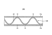
図7を用いて、第4実施形態に係るパネル構造体の構成について説明する。図7は、第4実施形態に係るパネル構造体の断面を模式的に示す図である。
図7を用いて、第4実施形態に係るパネル構造体の構成について説明する。図7は、第4実施形態に係るパネル構造体の断面を模式的に示す図である。
図7に示すように、第4実施形態に係るパネル構造体10Cは、コア部材12Bと、フェイスプレート14aと、フェイスプレート14bと、融着部16と、金属薄膜24と、を備える。パネル構造体10Cは、金属薄膜24を備える点で、図5に示すパネル構造体10Bと異なる。
図7に示す例では、金属薄膜24は、フェイスプレート14bの一方の面に形成されているが、これに限定されない。金属薄膜24は、フェイスプレート14aおよびフェイスプレート14bの少なくとも一方において、少なくとも一方の面に形成され得る。金属薄膜24は、例えば、フェイスプレート14bに対し、金属を蒸着させたり、メッキ加工を施したりすることで形成され得る。金属薄膜24は、任意の金属であってよい。金属薄膜24は、その他の方法で形成されていてもよい。
第4実施形態に係るパネル構造体10Cは、フェイスプレート14aおよびフェイスプレート14bの少なくとも一方において、少なくも一方の面に金属薄膜24を有する。これにより、第4実施形態は、パネル構造体10Cで生じる輻射熱を低減することができる。
[第5実施形態]
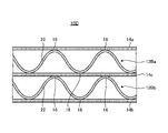
図8を用いて、第5実施形態に係るパネル構造体の構成について説明する。図8は、第5実施形態に係るパネル構造体の断面を模式的に示す図である。
図8を用いて、第5実施形態に係るパネル構造体の構成について説明する。図8は、第5実施形態に係るパネル構造体の断面を模式的に示す図である。
図8に示すように、第5実施形態に係るパネル構造体10Dは、コア部材12Baと、コア部材12Bbと、フェイスプレート14aと、フェイスプレート14bと、フェイスプレート14cと、融着部16と、を備える。パネル構造体10Dは、コア部材を複数備える点で、図5に示すパネル構造体10Bと異なる。
本実施形態では、融着部16は、コア部材12Baの一方の面において、コア部材12Baと、フェイスプレート14aとを結合する。融着部16は、コア部材12Baの他方の面において、コア部材12Baと、フェイスプレート14cとを結合する。融着部16は、コア部材12Bbの一方の面において、コア部材12Bbと、フェイスプレート14cとを結合する。融着部16は、コア部材12Bbの他方の面において、コア部材12Bbと、フェイスプレート14bとを結合する。なお、図8に示す例では、コア部材12Baと、コア部材12Bbとは、それぞれ、共通の1枚のフェイスプレート14cに結合されているが、本開示はこれに限られない。例えば、フェイスプレート14cは、コア部材12Baが結合されるフェイスプレートと、コア部材12Bbとが結合されるフェイスプレートとの、2枚のフェイスプレートが接合または融着された構造を有していてもよい。
コア部材12Baと、コア部材12Bbとは、それぞれの頂部が揃うように形成されていてもよいし、頂部がずれていてもよい。コア部材12Baと、コア部材12Bbとの形状は、異なっていてもよい。
パネル構造体10Dは、コア部材12Baと、フェイスプレート14aとの間に空気層を有する。パネル構造体10Dは、コア部材12Baと、フェイスプレート14cとの間に空気層を有する。パネル構造体10Dは、コア部材12Bbと、フェイスプレート14cとの間に空気層を有する。パネル構造体10Dは、コア部材12Bbと、フェイスプレート14bとの間に空気層を有する。すなわち、パネル構造体10Dは、図5に示すパネル構造体10Bと比べて、空気層の数が多い。
第5実施形態に係るパネル構造体10Dは、コア部材12Baと、コア部材12Bbとのようにコア部材を複数にすることで、空気層の体積を大きくすることができる。これにより、第5実施形態は、断熱性を向上させることができる。また、第5実施形態は、遮音性を向上させることができる。
[第6実施形態]
図9を用いて、第6実施形態に係るパネル構造体の構成について説明する。図9は、第6実施形態に係るパネル構造体の断面を模式的に示す図である。
図9を用いて、第6実施形態に係るパネル構造体の構成について説明する。図9は、第6実施形態に係るパネル構造体の断面を模式的に示す図である。
図9に示すように、第6実施形態に係るパネル構造体10Eは、コア部材12Bと、フェイスプレート14aと、フェイスプレート14bと、融着部16と、充填部材26と、を備える。パネル構造体10Eは、充填部材26を備える点で、図5に示すパネル構造体10Bと異なる。
充填部材26は、コア部材12Bと、フェイスプレート14aおよびフェイスプレート14bとの間に配置されている。充填部材26は、コア部材12Bと、フェイスプレート14aおよびフェイスプレート14bの間において、選択的に配置されてよい。充填部材26は、例えば、発泡ウレタンなどの断熱性および吸音性の少なくとも一方を持つ発泡性の部材で形成され得る。なお、充填部材26は、発泡性の部材に限定されず、断熱性および吸音性の少なくとも一方を持つその他の部材で形成されてもよい。
充填部材26を、コア部材12Bと、フェイスプレート14aおよびフェイスプレート14bとの間に配置する方法の一例について説明する。例えば、コア部材12Bと、フェイスプレート14aおよびフェイスプレート14bとを熱融着する前に、充填部材26を所定の形に賦形させて、コア部材12Bと、フェイスプレート14aおよびフェイスプレート14bとの間の空間に配置する。充填部材26は、コア部材12Bと、フェイスプレート14aおよびフェイスプレート14bとを熱融着する際の熱で溶融し、コア部材12Bと、フェイスプレート14aおよびフェイスプレート14bに張り付く。これにより、充填部材26は、コア部材12Bと、フェイスプレート14aおよびフェイスプレート14bとの間に配置される。
第6実施形態に係るパネル構造体10Eは、コア部材12Bと、フェイスプレート14aおよびフェイスプレート14bとの間に充填部材26を有する。これにより、第6実施形態は、断熱性を向上させることができる。また、第6実施形態は、遮音性を向上させることもできる。
[第6実施形態の変形例]
図10を用いて、第6実施形態の変形例に係るパネル構造体の構成について説明する。図10は、第6実施形態の変形例に係るパネル構造体の断面を示す模式的に示す図である。
図10を用いて、第6実施形態の変形例に係るパネル構造体の構成について説明する。図10は、第6実施形態の変形例に係るパネル構造体の断面を示す模式的に示す図である。
図10に示すように、第6実施形態の変形例に係るパネル構造体10Fは、コア部材12Baと、コア部材12Bbと、フェイスプレート14aと、フェイスプレート14bと、フェイスプレート14cと、融着部16と、充填部材26とを備える。パネル構造体10Fは、充填部材26を備える点で、図8に示すパネル構造体10Dと異なる。なお、図10に示す例では、コア部材12Baと、コア部材12Bbとは、それぞれ、共通の1枚のフェイスプレート14cに結合されているが、本開示はこれに限られない。例えば、フェイスプレート14cは、コア部材12Baが結合されるフェイスプレートと、コア部材12Bbとが結合されるフェイスプレートとの、2枚のフェイスプレートが結合または融着された構造を有していてもよい。
図10に示す例では、パネル構造体10Fは、コア部材12Ba側から図示しない熱源または音源から熱または音声を受けるものとする。この場合、充填部材26は、コア部材12Baと、フェイスプレート14aおよびフェイスプレート14cとの間に形成されていることが好ましい。すなわち、充填部材26は、コア部材が複数存在する場合には、熱源側または音源側に形成することが好ましい。
第6実施形態の変形例に係るパネル構造体10Fは、コア部材12Baと、フェイスプレート14aおよびフェイスプレート14cとの間に発泡部材を形成することで、熱または音声を直接受けている側から断熱または遮音することができる。これにより、第6実施形態の変形例は、断熱性を向上させることができる。また、第6実施形態の変形例は、遮音性を向上させることができる。
[第7実施形態]
図11を用いて、第7実施形態に係るパネル構造体の構成について説明する。図11は、第7実施形態に係るパネル構造体の断面を模式的に示す図である。
図11を用いて、第7実施形態に係るパネル構造体の構成について説明する。図11は、第7実施形態に係るパネル構造体の断面を模式的に示す図である。
図11に示すように、第7実施形態に係るパネル構造体10Gは、コア部材12Bと、フェイスプレート14aと、フェイスプレート14bと、融着部16と、流路28と、を備える。パネル構造体10Gは、流路28を備える点で、図5に示すパネル構造体10Bと異なる。
流路28は、コア部材12Bと、フェイスプレート14aおよびフェイスプレート14bとの間に形成されている。流路28は、コア部材12Bと、フェイスプレート14aおよびフェイスプレート14bとの間に流体を流す。流体は、例えば、気体および液体である。具体的には、流体は、例えば、空気および水であるが、これに限定されない。流路28は、コア部材12Bと、フェイスプレート14aおよびフェイスプレート14bとの間に流体を流すことで、パネル構造体10Gを冷却する。流路28は、内部に流れる流体の温度に応じて、例えば、パネル構造体10Gが車に設置されている場合には、車の車内などの外部の空気を冷却したり、加熱したりする。言い換えると、第7実施形態では、流路28に流れる流体の温度と、温度調節の対象となる温調対象物の温度との相関関係により、温調対象物を冷却したり、加熱したりすることができる。例えば、第7実施形態では、温調対象物の温度を計測して、温度の測定結果に基づいてフィードバック制御により、流体の温度を決定してもよい。これにより、第7実施形態では、温調対象物の温度に応じて、流体の温度を制御することで、温調対象物を適切に冷却したり、加熱したりすることができる。
第7実施形態では、流路28に流体を流すことで、遮音性を向上させてもよい。例えば、流体が気体である場合と、液体である場合とでは、音の伝搬特性は変化する。音の伝搬特性は、流体の粘度などの物理特性に応じても変化する。すなわち、流路28に流す流体の状態と、物理特性とを選択することによって、図示しない音源からパネル構造体10Gが受ける音声に対する遮音性を向上させることができる。また、遮音したい音声の周波数帯域が予め分かっている場合などには、その周波数帯域の音声を減衰させることのできる流体を選択して流路28に流すことで、その音声を効果的に減衰することができる。すなわち、第7実施形態では、パネル構造体10Gが受ける音声に応じて、流路28に流す流体の状態、および粘度などの物理特性を選択することで、遮音性を向上させることができる。
第7実施形態に係るパネル構造体10Gは、コア部材12Bと、フェイスプレート14aおよびフェイスプレート14bとの間に流体を流すことで、パネル構造体10Gを冷却することができる。これにより、第7実施形態は、断熱性を向上させることができる。また、第7実施形態は、外部の熱よりも低い温度の流体を流路28に流すことで、車の車内などの外部の空気を冷却することができる。さらに、第7実施形態は、外部の熱よりも高い温度の流体を流路28に流すことで、車の車内などの外部の空気を加熱することができる。
[第7実施形態の変形例]
図12を用いて、第7実施形態の変形例に係るパネル構造体の構成について説明する。図12は、第7実施形態の変形例に係るパネル構造体の断面を模式的に示す図である。
図12を用いて、第7実施形態の変形例に係るパネル構造体の構成について説明する。図12は、第7実施形態の変形例に係るパネル構造体の断面を模式的に示す図である。
図12に示すように、第7実施形態の変形例に係るパネル構造体10Hは、コア部材12Baと、コア部材12Bbと、フェイスプレート14aと、フェイスプレート14bと、フェイスプレート14cと、融着部16と、流路28を備える。パネル構造体10Hは、流路28を備える点で、図8に示すパネル構造体10Dと異なる。
図12に示す例では、パネル構造体10Hは、コア部材12Ba側から図示しない熱源による熱を受けるものとする。この場合、流路28は、コア部材12Baと、フェイスプレート14aおよびフェイスプレート14cとの間に形成されていることが好ましい。すなわち、流路28は、コア部材が複数存在する場合には、熱源側に形成することが好ましい。
第7実施形態の変形例に係るパネル構造体10Hは、コア部材12Baと、フェイスプレート14aおよびフェイスプレート14cとの間に流体を流すことで、熱を直接受けている側を冷却することができる。これにより、第7実施形態の変形例は、断熱性を向上させることができる。
[第8実施形態]
図13を用いて、第8実施形態に係るパネル構造体の構成について説明する。図13は、第8実施形態に係るパネル構造体の断面を模式的に示す図である。
図13を用いて、第8実施形態に係るパネル構造体の構成について説明する。図13は、第8実施形態に係るパネル構造体の断面を模式的に示す図である。
図13に示すように、第8実施形態に係るパネル構造体10Iは、コア部材12Bと、フェイスプレート14aと、フェイスプレート14bと、融着部16と、孔部30と、を備える。パネル構造体10Iは、孔部30を備える点で、図5に示すパネル構造体10Bと異なる。
孔部30は、コア部材12Bと、フェイスプレート14aと、フェイスプレート14bとに形成され得る。孔部30は、例えば、コア部材12Bと、フェイスプレート14aと、フェイスプレート14bとのうちの少なくとも1つに形成され得る。パネル構造体10Iは、孔部30を有することにより、音の共鳴効果により発生する音を吸音する。パネル構造体Hは、例えば、孔部30を有することで、内部で音を反射させて音をキャンセルさせる。
孔部30の数および孔部30が形成される位置は、設計に応じて任意に変更され得る。例えば、孔部30の数および孔部30が形成される位置は、吸音したい音の大きさ、音の周波数、および音の音域などに応じて、任意に変更され得る。例えば、コア部材を複数使用する場合であっても、複数のコア部材、およびフェイスプレートに任意に孔部30を形成してよい。
第8実施形態に係るパネル構造体10Iは、孔部30を形成することで、音の共鳴効果により、パネル構造体10Iから発生する音を吸音することができる。これにより、第8実施形態は、フェイスプレート14aおよびフェイスプレート14bの一方で発生した騒音が、他方に伝わってしまうことを防止することができる。
[第8実施形態の変形例]
図13に図示のパネル構造体10Iにおいて、コア部材12Bと、フェイスプレート14aと、フェイスプレート14bの少なくも1つを多孔質の樹脂または不織布の炭素繊維を含む樹脂から形成されてもよい。この場合、樹脂は、孔質の樹脂または不織布の炭素繊維を含む炭素繊維強化プラスチックであることが好ましい。多孔質の樹脂などから形成されたコア部材12Bと、フェイスプレート14aと、フェイスプレート14bとは、微小な孔を有する。このため、コア部材12Bと、フェイスプレート14aと、フェイスプレート14bとを多孔質の樹脂などで形成することで、孔部30を形成した場合と同様に、音を共鳴させることができる。なお、第8実施形態の変形例では、孔部30は、必ずしも形成しなくてもよい。
図13に図示のパネル構造体10Iにおいて、コア部材12Bと、フェイスプレート14aと、フェイスプレート14bの少なくも1つを多孔質の樹脂または不織布の炭素繊維を含む樹脂から形成されてもよい。この場合、樹脂は、孔質の樹脂または不織布の炭素繊維を含む炭素繊維強化プラスチックであることが好ましい。多孔質の樹脂などから形成されたコア部材12Bと、フェイスプレート14aと、フェイスプレート14bとは、微小な孔を有する。このため、コア部材12Bと、フェイスプレート14aと、フェイスプレート14bとを多孔質の樹脂などで形成することで、孔部30を形成した場合と同様に、音を共鳴させることができる。なお、第8実施形態の変形例では、孔部30は、必ずしも形成しなくてもよい。
[第9実施形態]
図14を用いて、第9実施形態に係るパネル構造体の構成について説明する。図14は、第9実施形態に係るパネル構造体の断面を模式的に示す図である。
図14を用いて、第9実施形態に係るパネル構造体の構成について説明する。図14は、第9実施形態に係るパネル構造体の断面を模式的に示す図である。
図14に示すように、第9実施形態に係るパネル構造体10Jは、コア部材12Bと、フェイスプレート14aと、フェイスプレート14bと、融着部16と、吸音部材32と、を備える。パネル構造体10Jは、吸音部材32を備える点で、図5に示すパネル構造体10Bと異なる。
吸音部材32は、コア部材12Bと、フェイスプレート14aおよびフェイスプレート14bとの間に配置されている。吸音部材32は、コア部材12Bと、フェイスプレート14aおよびフェイスプレート14bの間において、選択的に配置されてよい。吸音部材32は、例えば、吸音効果を奏する任意の部材で形成され得る。
第9実施形態に係るパネル構造体10Jは、コア部材12Bと、フェイスプレート14aおよびフェイスプレート14bとの間に吸音部材32を有する。これにより、第9実施形態は、遮音性を向上させることができる。
[第10実施形態]
図15を用いて、第10実施形態に係るパネル構造体の構成について説明する。図15は、第10実施形態に係るパネル構造体の断面を模式的に示す図である。
図15を用いて、第10実施形態に係るパネル構造体の構成について説明する。図15は、第10実施形態に係るパネル構造体の断面を模式的に示す図である。
図15に示すように、第10実施形態に係るパネル構造体10Kは、コア部材12Bと、フェイスプレート14aと、フェイスプレート14bと、接着部34と、充填部材26と、を備える。パネル構造体10Kは、融着部16の代わりに接着部34を備える点と、充填部材26を備える点で、図5に示すパネル構造体10Bと異なる。
接着部34は、コア部材12Bの一方の面において、コア部材12Bと、フェイスプレート14aとを結合する。接着部34は、波部22の頂部と、フェイスプレート14aの一方の面との間に形成されている。接着部34は、複数の波部22の頂部と、フェイスプレート14aの一方の面との間に選択的に形成されている。接着部34は、例えば、パネル構造体10Kに求められる剛性および耐衝撃性特性に応じて、複数の波部22の頂部と、フェイスプレート14aの一方の面との間に選択的に形成される。接着部34は、例えば、樹脂用の接着剤を用いて波部22と、フェイスプレート14aとを接着させて乾燥させることにより形成され得る。樹脂用の接着剤は周知のものを用いてよい。
接着部34は、コア部材12Bの他方の面において、コア部材12Bと、フェイスプレート14bとを結合する。接着部34は、波部22の頂部と、フェイスプレート14bの一方の面との間に形成されている。接着部34は、複数の波部22の頂部と、フェイスプレート14bの一方の面との間に選択的に形成されている。接着部34は、例えば、パネル構造体10Kに求められる剛性および耐衝撃性特性に応じて、複数の波部22の頂部と、フェイスプレート14bの一方の面との間に選択的に形成される。接着部34は、樹脂用の接着剤を用いて波部22と、フェイスプレート14bとを接着させて乾燥させることにより形成され得る。
充填部材26を、コア部材12Bと、フェイスプレート14aおよびフェイスプレート14bとの間に配置する方法の一例について説明する。例えば、コア部材12Bと、フェイスプレート14aおよびフェイスプレート14bとを接着剤で接着する前に、充填部材26を所定の形に賦形させて、コア部材12Bと、フェイスプレート14aおよびフェイスプレート14bとの間の空間に配置する。充填部材26は、コア部材12Bと、フェイスプレート14aおよびフェイスプレート14bとを接着部34で結合した後、図示しない熱源を用いて加熱することにより溶融し、コア部材12Bと、フェイスプレート14aおよびフェイスプレート14bに張り付く。これにより、充填部材26は、コア部材12Bと、フェイスプレート14aおよびフェイスプレート14bとの間に配置される。
第10実施形態に係るパネル構造体10Kは、接着部34で結合されたコア部材12Bと、フェイスプレート14aおよびフェイスプレート14bとの間に充填部材26を有する。これにより、第10実施形態は、接着剤で結合されているパネル構造体10Kの断熱性を向上させることができる。
なお、第10実施形態においては、パネル構造体10Kの断熱性を向上させるために、充填部材26の代わりにコア部材14Bと、フェイスプレート14aおよびフェイスプレート14bとの間に、図11で示した流体が流れる流路28が形成されてもよい。
[第11実施形態]
図16を用いて、第11実施形態に係るパネル構造体の構成について説明する。図16は、第11実施形態に係るパネル構造体の断面を模式的に示す図である。
図16を用いて、第11実施形態に係るパネル構造体の構成について説明する。図16は、第11実施形態に係るパネル構造体の断面を模式的に示す図である。
図16に示すように、第11実施形態に係るパネル構造体10Lは、コア部材12Bと、フェイスプレート14aと、フェイスプレート14bと、接着部34と、吸音部材32と、を備える。パネル構造体10Lは、充填部材26の代わりに吸音部材32を備える点で、図15に示すパネル構造体10Kと異なる。
吸音部材32は、接着部34で結合されたコア部材12Bと、フェイスプレート14aおよびフェイスプレート14bとの間に配置されている。吸音部材32は、コア部材12Bと、フェイスプレート14aおよびフェイスプレート14bの間において、選択的に配置されてよい。吸音部材32は、例えば、吸音効果を奏する任意の部材で形成され得る。
第11実施形態に係るパネル構造体10Lは、接着部34で結合されたコア部材12Bと、フェイスプレート14aおよびフェイスプレート14bとの間に吸音部材32を有する。これにより、第11実施形態は、遮音性を向上させることができる。
なお、第11実施形態においては、パネル構造体10Lの遮音性を向上させるために、吸音部材32の代わりにコア部材14Bと、フェイスプレート14aおよびフェイスプレート14bとの少なくとも1つに、図13で示した孔部30が形成されてもよい。
また、本開示では、第10実施形態および第11実施形態に示した形態に限定されず、第1実施形態から第9実施形態に示した、各コア部材および各フェイスプレートを融着に代えて、樹脂用の接着材で接着してもよい。
[効果]
実施形態に記載のパネル構造体は、例えば以下のように把握される。
実施形態に記載のパネル構造体は、例えば以下のように把握される。
第1の態様のパネル構造体は、熱可塑性を有し、少なくとも一方の面に複数の凸部18を有する板状のコア部材12と、複数の凸部18に配置され、熱可塑性を有する板状のフェイスプレート14と、コア部材12と、複数の凸部18との間に選択的に形成され、コア部材12と、フェイスプレート14とを結合する融着部16と、を備える。
第1の態様のパネル構造体は、コア部材12と、フェイスプレート14とを、熱融着により形成された融着部16により結合されている。これにより、第1の態様のパネル構造体は、コア部材12と、フェイスプレート14との接合の信頼性を向上させることができる。また、第1の態様のパネル構造体は、コア部材12と、フェイスプレート14とは、融着部16により結合することで、ボルトなどの接合部材が不要となり、重量増加を抑制することができる。
第2の態様のパネル構造体は、凸部18は、コア部材12の両面に形成されている。これにより、第2の態様のパネル構造体は、コア部材12の両面において、コア部材12と、フェイスプレート14との接合の信頼性を向上させることができる。
第3の態様のパネル構造体は、凸部18は、コア部材12の表面に形成された連続的な波部22である。これにより、第3の態様のパネル構造体は、コア部材12の形状が波形形状である場合に、コア部材12と、フェイスプレート14との接合の信頼性を向上させることができる。
第4の態様のパネル構造体は、フェイスプレート14の少なくとも一方の面に形成された金属薄膜を備える。これにより、第4の態様のパネル構造体は、輻射熱を低減することができる。
第5の態様のパネル構造体は、コア部材12と、フェイスプレート14との間の空間に配置された充填部材26を備える。これにより、第5の態様のパネル構造体は、断熱性を向上させることができる。また、第5の態様のパネル構造体は、遮音性を向上させることができる。
第6の態様のパネル構造体は、コア部材12を複数備える。これにより、第6の態様のパネル構造体は、内部の空気層の数を多くすることができる。その結果、第6の態様のパネル構造体は、断熱性を向上させることができる。また、第6の態様のパネル構造体は、遮音性を向上させることができる。
第7の態様のパネル構造体は、コア部材12と、フェイスプレート14との間に流体が流れる流路28を備える。これにより、第7の態様のパネル構造体は、内部を冷却することができる。その結果、第7の態様のパネル構造体は、断熱性を向上させることができる。また、第7の態様のパネル構造体は、流体の温度を適宜調整することで、車の車内などの温度を冷却したり、加熱したりすることができる。
第8の態様のパネル構造体は、流体は、液体または気体である。これにより、第8の態様のパネル構造体は、任意の流体を用いて容易に内部を冷却することができる。その結果、第8の態様のパネル構造体は、断熱性を容易に向上させることができる。また、第8の態様のパネル構造体は、任意の流体を用いて、車の車内などの温度を冷却したり、加熱したりすることができる。
第9の態様のパネル構造体は、コア部材12およびフェイスプレート14の少なくとも一方に選択的に形成された孔部30を有する。これにより、第9の態様のパネル構造体は、内部で音を共鳴させることができる。その結果、第9の態様のパネル構造体は、フェイスプレート14の一方で発生させた騒音を他方に伝わってしまうことを防止できるので、遮音性を向上させることができる。
第10の態様のパネル構造体は、フェイスプレート14は、多孔質樹脂または不織布の炭素繊維を含む樹脂で形成されている。これにより、第10の態様のパネル構造体は、内部で音を共鳴させることができる。その結果、第10の態様のパネル構造体は、遮音性を向上させることができる。
以上、本開示の実施形態を説明したが、これら実施形態の内容により本開示が限定されるものではない。また、前述した構成要素には、当業者が容易に想定できるもの、実質的に同一のもの、いわゆる均等の範囲のものが含まれる。さらに、前述した構成要素は適宜組み合わせることが可能である。さらに、前述した実施形態の要旨を逸脱しない範囲で構成要素の種々の省略、置換又は変更を行うことができる。
10 パネル構造体
12 コア部材
14 フェイスプレート
16 融着部
18 凸部
20 凹部
22 波部
24 金属薄膜
26 充填部材
28 流路
30 孔部
32 吸音部材
34 接着部
12 コア部材
14 フェイスプレート
16 融着部
18 凸部
20 凹部
22 波部
24 金属薄膜
26 充填部材
28 流路
30 孔部
32 吸音部材
34 接着部
Claims (11)
- 熱可塑性を有し、少なくとも一方の面に複数の凸部を有する板状のコア部材と、
複数の前記凸部に配置され、熱可塑性を有する板状のフェイスプレートと、
前記コア部材と、複数の前記凸部との間に選択的に形成され、前記コア部材と、前記フェイスプレートとを結合する融着部と、
を備える、パネル構造体。 - 前記凸部は、前記コア部材の両面に形成されている、
請求項1に記載のパネル構造体。 - 前記凸部は、前記コア部材の表面に形成された連続的な波部である、
請求項1または2に記載のパネル構造体。 - 前記フェイスプレートの少なくとも一方の面に形成された金属薄膜を備える、
請求項1から3のいずれか1項に記載のパネル構造体。 - 前記コア部材と、前記フェイスプレートとの間の空間に配置された充填部材を備える、
請求項1から4のいずれか1項に記載のパネル構造体。 - 前記コア部材を複数備える、
請求項1から5のいずれか1項に記載のパネル構造体。 - 前記コア部材と、前記フェイスプレートとの間に流体が流れる流路を備える、
請求項1から6のいずれか1項に記載のパネル構造体。 - 前記流体は、液体または気体である、
請求項7に記載のパネル構造体。 - 前記コア部材および前記フェイスプレートの少なくとも一方に選択的に形成された孔部を有する、
請求項1から8のいずれか1項に記載のパネル構造体。 - 前記フェイスプレートは、多孔質樹脂または不織布の炭素繊維を含む樹脂で形成されている、
請求項1から9のいずれか1項に記載のパネル構造体。 - 前記コア部材と、前記フェイスプレートとの間に配置された吸音部材を備える、
請求項1から10のいずれか1項に記載のパネル構造体。
Priority Applications (3)
| Application Number | Priority Date | Filing Date | Title |
|---|---|---|---|
| US18/276,330 US20240096307A1 (en) | 2021-02-17 | 2022-02-14 | Panel structure |
| EP22756128.9A EP4280207A4 (en) | 2021-02-17 | 2022-02-14 | PANEL STRUCTURE |
| US18/238,158 US20230398763A1 (en) | 2021-02-17 | 2023-08-25 | Panel structure |
Applications Claiming Priority (4)
| Application Number | Priority Date | Filing Date | Title |
|---|---|---|---|
| JP2021023583 | 2021-02-17 | ||
| JP2021-023583 | 2021-02-17 | ||
| JP2021084630A JP7824734B2 (ja) | 2021-02-17 | 2021-05-19 | パネル構造体 |
| JP2021-084630 | 2021-05-19 |
Related Child Applications (2)
| Application Number | Title | Priority Date | Filing Date |
|---|---|---|---|
| US18/276,330 A-371-Of-International US20240096307A1 (en) | 2021-02-17 | 2022-02-14 | Panel structure |
| US18/238,158 Continuation-In-Part US20230398763A1 (en) | 2021-02-17 | 2023-08-25 | Panel structure |
Publications (1)
| Publication Number | Publication Date |
|---|---|
| WO2022176810A1 true WO2022176810A1 (ja) | 2022-08-25 |
Family
ID=82930520
Family Applications (1)
| Application Number | Title | Priority Date | Filing Date |
|---|---|---|---|
| PCT/JP2022/005714 Ceased WO2022176810A1 (ja) | 2021-02-17 | 2022-02-14 | パネル構造体 |
Country Status (3)
| Country | Link |
|---|---|
| US (1) | US20240096307A1 (ja) |
| EP (1) | EP4280207A4 (ja) |
| WO (1) | WO2022176810A1 (ja) |
Cited By (1)
| Publication number | Priority date | Publication date | Assignee | Title |
|---|---|---|---|---|
| WO2023203874A1 (ja) * | 2022-04-18 | 2023-10-26 | 三菱重工業株式会社 | 断熱構造及び断熱構造の製造装置 |
Families Citing this family (1)
| Publication number | Priority date | Publication date | Assignee | Title |
|---|---|---|---|---|
| US20230398763A1 (en) * | 2021-02-17 | 2023-12-14 | Mitsubishi Heavy Industries, Ltd. | Panel structure |
Citations (6)
| Publication number | Priority date | Publication date | Assignee | Title |
|---|---|---|---|---|
| JPS5537841U (ja) * | 1978-08-31 | 1980-03-11 | ||
| JPS60129406U (ja) * | 1984-02-08 | 1985-08-30 | 株式会社アイジ−技術研究所 | 防音パネル |
| JPH10168216A (ja) * | 1996-12-12 | 1998-06-23 | Riboole:Kk | 軽量断熱パネル |
| JP2003053887A (ja) | 2001-08-22 | 2003-02-26 | Kobe Steel Ltd | 複合パネル |
| JP2004009493A (ja) * | 2002-06-06 | 2004-01-15 | Mamoru Kamo | 板状中空構造体とその製造方法 |
| JP2020066219A (ja) * | 2018-10-26 | 2020-04-30 | 森田技研工業株式会社 | プラスチック積層体の製造方法 |
Family Cites Families (15)
| Publication number | Priority date | Publication date | Assignee | Title |
|---|---|---|---|---|
| US5866235A (en) * | 1997-02-21 | 1999-02-02 | Eften, Inc. | All synthetic fiber interior trim substrate |
| US5892187A (en) * | 1997-12-17 | 1999-04-06 | United Technologies Corporation | Tunable recyclable headliner |
| JP2001260765A (ja) * | 2000-03-21 | 2001-09-26 | Tokai Chem Ind Ltd | 車両内装品及びその製造方法 |
| GB0114691D0 (en) * | 2001-06-15 | 2001-08-08 | Rasmussen O B | Laminates of films and methods and apparatus for their manufacture |
| JP5532522B2 (ja) * | 2008-10-31 | 2014-06-25 | キョーラク株式会社 | サンドイッチパネルおよびサンドイッチパネル用芯材の成形方法、ならびにサンドイッチパネルの成形方法 |
| JP2012141405A (ja) * | 2010-12-28 | 2012-07-26 | Nagoya Oil Chem Co Ltd | 緩衝吸音材 |
| FR2982193B1 (fr) * | 2011-11-07 | 2014-06-27 | Orion Financement | Bande de produit isolant multicouche, element isolant resultant de la decoupe d'une telle bande et complexe isolant forme a partir de tels elements isolant |
| US9027706B2 (en) * | 2013-02-11 | 2015-05-12 | Federal-Mogul Powertrain, Inc. | Enhanced, lightweight acoustic scrim barrier |
| JP6023845B1 (ja) * | 2015-04-28 | 2016-11-09 | 加川 清二 | 電磁波吸収吸音パネル |
| US10414481B2 (en) * | 2017-02-14 | 2019-09-17 | Rohr, Inc. | Method for forming a structural panel |
| US10695986B2 (en) * | 2017-08-22 | 2020-06-30 | Rohr, Inc. | Method for forming a structural panel |
| US11066147B2 (en) * | 2018-07-10 | 2021-07-20 | Rohr, Inc. | Structured panel with integrated skin and sidewalls |
| EP3643471A1 (en) * | 2018-10-26 | 2020-04-29 | Morita Giken Inc. | Plastic laminated structure and method for producing the same |
| US11398214B2 (en) * | 2018-12-14 | 2022-07-26 | Rohr, Inc. | Forming a structured panel with one or more structural reinforcements |
| US20230398763A1 (en) * | 2021-02-17 | 2023-12-14 | Mitsubishi Heavy Industries, Ltd. | Panel structure |
-
2022
- 2022-02-14 WO PCT/JP2022/005714 patent/WO2022176810A1/ja not_active Ceased
- 2022-02-14 US US18/276,330 patent/US20240096307A1/en not_active Abandoned
- 2022-02-14 EP EP22756128.9A patent/EP4280207A4/en active Pending
Patent Citations (6)
| Publication number | Priority date | Publication date | Assignee | Title |
|---|---|---|---|---|
| JPS5537841U (ja) * | 1978-08-31 | 1980-03-11 | ||
| JPS60129406U (ja) * | 1984-02-08 | 1985-08-30 | 株式会社アイジ−技術研究所 | 防音パネル |
| JPH10168216A (ja) * | 1996-12-12 | 1998-06-23 | Riboole:Kk | 軽量断熱パネル |
| JP2003053887A (ja) | 2001-08-22 | 2003-02-26 | Kobe Steel Ltd | 複合パネル |
| JP2004009493A (ja) * | 2002-06-06 | 2004-01-15 | Mamoru Kamo | 板状中空構造体とその製造方法 |
| JP2020066219A (ja) * | 2018-10-26 | 2020-04-30 | 森田技研工業株式会社 | プラスチック積層体の製造方法 |
Non-Patent Citations (1)
| Title |
|---|
| See also references of EP4280207A4 |
Cited By (1)
| Publication number | Priority date | Publication date | Assignee | Title |
|---|---|---|---|---|
| WO2023203874A1 (ja) * | 2022-04-18 | 2023-10-26 | 三菱重工業株式会社 | 断熱構造及び断熱構造の製造装置 |
Also Published As
| Publication number | Publication date |
|---|---|
| EP4280207A4 (en) | 2024-05-29 |
| EP4280207A1 (en) | 2023-11-22 |
| US20240096307A1 (en) | 2024-03-21 |
Similar Documents
| Publication | Publication Date | Title |
|---|---|---|
| EP2931497B1 (en) | Joining composite components using low temperature thermoplastic film fusion | |
| KR101983613B1 (ko) | 열경화성 폴리머 컴포넌트에 열가소성 폴리머를 접합하기 위한 방법 | |
| RU2463163C2 (ru) | Способ соединения термопластичного материала с материалом волокнистого композита | |
| JP4361036B2 (ja) | 車両用防音材 | |
| AU2019304113B2 (en) | Method for welding parts made of thermoplastic material | |
| US20240096307A1 (en) | Panel structure | |
| US10611328B2 (en) | Composite material structural member and method of manufacturing the composite material structural member | |
| JP2014076565A (ja) | 繊維強化熱可塑樹脂の接合体およびその接合方法 | |
| US20230398763A1 (en) | Panel structure | |
| JP2023011513A (ja) | 複合材サンドイッチ構造体用の発泡シートコアおよびその作製方法 | |
| JP7824734B2 (ja) | パネル構造体 | |
| WO2019111571A1 (ja) | 複合材料の接合方法及び複合材料 | |
| JP5325445B2 (ja) | ダッシュインシュレーター | |
| TW201708007A (zh) | 引擎護蓋裝置、連接至少一安裝部件至此引擎護蓋裝置的護蓋的方法及用於製作此引擎護蓋裝置的裝置 | |
| CN115534322A (zh) | 将第一纤维复合零件连结到第二纤维复合零件的方法 | |
| KR101892648B1 (ko) | 컨테이너 적재구조물용 복합패널 | |
| JPS63199915A (ja) | 繊維強化プラスチツク製動力推進軸 | |
| JP4804481B2 (ja) | 吸音部材を備える被覆部材 | |
| JP7656496B2 (ja) | 電池ユニット及び電池ユニットの製造方法 | |
| JP2006272709A (ja) | 車両用天井材及びその製造方法。 | |
| JP5959959B2 (ja) | 中空構造板の製造方法 | |
| KR101293470B1 (ko) | 차량용 방음재 | |
| JPH05185540A (ja) | 構造用熱可塑性複合材の成形体及びその製造方法 | |
| Vijayakumar et al. | INNOVATIVE WELDING-BASED APPROACH FOR SKIN/CORE BONDING IN THERMOPLASTIC SANDWICH STRUCTURES | |
| KR970002938B1 (ko) | 열가소성 합성수지로 된 경량 적층판의 적층방법 |
Legal Events
| Date | Code | Title | Description |
|---|---|---|---|
| 121 | Ep: the epo has been informed by wipo that ep was designated in this application |
Ref document number: 22756128 Country of ref document: EP Kind code of ref document: A1 |
|
| WWE | Wipo information: entry into national phase |
Ref document number: 18276330 Country of ref document: US |
|
| ENP | Entry into the national phase |
Ref document number: 2022756128 Country of ref document: EP Effective date: 20230814 |
|
| NENP | Non-entry into the national phase |
Ref country code: DE |