WO2022190198A1 - 推定装置、推定方法およびプログラム - Google Patents
推定装置、推定方法およびプログラム Download PDFInfo
- Publication number
- WO2022190198A1 WO2022190198A1 PCT/JP2021/009228 JP2021009228W WO2022190198A1 WO 2022190198 A1 WO2022190198 A1 WO 2022190198A1 JP 2021009228 W JP2021009228 W JP 2021009228W WO 2022190198 A1 WO2022190198 A1 WO 2022190198A1
- Authority
- WO
- WIPO (PCT)
- Prior art keywords
- abnormal
- data
- byte
- vector
- vector data
- Prior art date
- Legal status (The legal status is an assumption and is not a legal conclusion. Google has not performed a legal analysis and makes no representation as to the accuracy of the status listed.)
- Ceased
Links
Images



Classifications
-
- G—PHYSICS
- G06—COMPUTING OR CALCULATING; COUNTING
- G06F—ELECTRIC DIGITAL DATA PROCESSING
- G06F9/00—Arrangements for program control, e.g. control units
- G06F9/06—Arrangements for program control, e.g. control units using stored programs, i.e. using an internal store of processing equipment to receive or retain programs
- G06F9/30—Arrangements for executing machine instructions, e.g. instruction decode
- G06F9/30003—Arrangements for executing specific machine instructions
- G06F9/30007—Arrangements for executing specific machine instructions to perform operations on data operands
- G06F9/30036—Instructions to perform operations on packed data, e.g. vector, tile or matrix operations
-
- H—ELECTRICITY
- H04—ELECTRIC COMMUNICATION TECHNIQUE
- H04L—TRANSMISSION OF DIGITAL INFORMATION, e.g. TELEGRAPHIC COMMUNICATION
- H04L63/00—Network architectures or network communication protocols for network security
- H04L63/14—Network architectures or network communication protocols for network security for detecting or protecting against malicious traffic
- H04L63/1408—Network architectures or network communication protocols for network security for detecting or protecting against malicious traffic by monitoring network traffic
-
- G—PHYSICS
- G06—COMPUTING OR CALCULATING; COUNTING
- G06N—COMPUTING ARRANGEMENTS BASED ON SPECIFIC COMPUTATIONAL MODELS
- G06N3/00—Computing arrangements based on biological models
- G06N3/02—Neural networks
- G06N3/08—Learning methods
- G06N3/0895—Weakly supervised learning, e.g. semi-supervised or self-supervised learning
-
- H—ELECTRICITY
- H04—ELECTRIC COMMUNICATION TECHNIQUE
- H04L—TRANSMISSION OF DIGITAL INFORMATION, e.g. TELEGRAPHIC COMMUNICATION
- H04L63/00—Network architectures or network communication protocols for network security
- H04L63/14—Network architectures or network communication protocols for network security for detecting or protecting against malicious traffic
- H04L63/1408—Network architectures or network communication protocols for network security for detecting or protecting against malicious traffic by monitoring network traffic
- H04L63/1425—Traffic logging, e.g. anomaly detection
-
- G—PHYSICS
- G06—COMPUTING OR CALCULATING; COUNTING
- G06F—ELECTRIC DIGITAL DATA PROCESSING
- G06F40/00—Handling natural language data
- G06F40/20—Natural language analysis
- G06F40/279—Recognition of textual entities
-
- G—PHYSICS
- G06—COMPUTING OR CALCULATING; COUNTING
- G06F—ELECTRIC DIGITAL DATA PROCESSING
- G06F40/00—Handling natural language data
- G06F40/30—Semantic analysis
-
- G—PHYSICS
- G06—COMPUTING OR CALCULATING; COUNTING
- G06N—COMPUTING ARRANGEMENTS BASED ON SPECIFIC COMPUTATIONAL MODELS
- G06N3/00—Computing arrangements based on biological models
- G06N3/02—Neural networks
- G06N3/04—Architecture, e.g. interconnection topology
- G06N3/045—Combinations of networks
Definitions
- the present invention relates to an estimation device, an estimation method, and a program.
- OTDS Operational Technology Intrusion Detection System
- OT-IDS Operational Technology Intrusion Detection System
- Packets transmitted and received through such a communication network need to be detected without missing even a small amount of illegal rewriting such as one byte. For example, an unexpected operation can cause a serious accident, such as changing the temperature setting value by one digit due to unauthorized rewriting.
- Non-Patent Document 1 There are tools for monitoring networks (see Non-Patent Document 1 and Non-Patent Document 2). These tools allow you to monitor and analyze data sent and received on your network.
- the present invention has been made in view of the above circumstances, and an object of the present invention is to provide a technology that can estimate abnormal bytes in abnormal packets.
- the estimating device of one aspect of the present invention uses a model that converts packet data into vector data that associates each byte of the packet data with each vector representing the characteristics of the value of each byte, and detects abnormal packet data.
- a conversion unit that converts the data into abnormal vector data, and extracts normal vector data having a relatively high degree of similarity with the abnormal vector data from a plurality of normal vector data obtained by converting a plurality of normal packet data using the model.
- an extracting unit, and an estimating unit that estimates an abnormal byte in the abnormal packet data from a degree of similarity between a vector corresponding to each byte of the abnormal vector data and a vector corresponding to each byte of the extracted normal vector data.
- An estimation method uses a model in which a computer converts packet data into vector data in which each byte of the packet data is associated with each vector representing the characteristics of the value of each byte.
- Packet data is converted into abnormal vector data
- the computer extracts normal vectors having a relatively high degree of similarity to the abnormal vector data from a plurality of normal vector data obtained by converting a plurality of normal packet data using the model.
- data is extracted, and the computer identifies an abnormal byte in the abnormal packet data from the degree of similarity between a vector corresponding to each byte of the abnormal vector data and a vector corresponding to each byte of the extracted normal vector data; presume.
- One aspect of the present invention is a program that causes a computer to function as the estimation device.
- FIG. 1 is a diagram illustrating functional blocks of an estimation device according to an embodiment of the present invention.
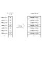
- FIG. 2 is a diagram illustrating an example of data converted by a model.
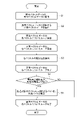
- FIG. 3 is a flowchart showing an example of processing of the estimation method.
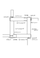
- FIG. 4 is a diagram for explaining each device of the estimation device evaluation system.
- FIG. 5 is a diagram illustrating an example of packets obtained by the evaluation system.
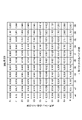
- FIG. 6 is a diagram illustrating an example of a similarity matrix obtained by the evaluation system.
- FIG. 7 is a diagram explaining the hardware configuration of a computer used in the estimation device.
- An estimation device 1 An estimation device 1 according to an embodiment of the present invention will be described with reference to FIG.
- the estimating device 1 estimates and outputs an abnormal byte in the abnormal packet.
- the estimating device 1 compares an abnormal packet determined to be abnormal by another system and a normal packet determined to be normal by another system to estimate an abnormal byte in the input abnormal packet.
- normal packets and abnormal packets are each collected in a communication network of one operation technology.
- the other system may use any method to determine whether the packet is normal or abnormal, and the method of determination does not matter in the embodiment of the present invention.
- the estimating device 1 combines model data 11, normal vector data group 12, abnormal packet data 15, abnormal vector data 16, normal vector data 17, and abnormal bytes 18 with conversion unit 21, generation unit 22, extraction unit 23, and Each function of the estimation unit 24 is provided. Each data is stored in memory 902 or storage 903 . Each function is implemented in the CPU 901 .
- the model data 11 specifies a model for converting packet data into vector data.
- the vector data associates each byte of the packet data with each vector representing the characteristics of the value of each byte.
- the model data 11 is generated by learning the value of each byte of a plurality of normal packet data of the normal vector data group 12 by the generation unit 22 which will be described later.
- the characteristics of each byte value are calculated by comparing with each byte value of a plurality of normal packet data.
- the model data 11 specifies a model that converts each byte of the input packet data into an appropriate fixed-length vector in consideration of the positional relationship of each byte.
- the appropriate fixed-length vector means a vector from which the abnormal byte 18 can be estimated by comparing the abnormal vector data 16 and the normal vector data 17 in the estimating unit 24, which will be described later. For example, as shown in FIG. 2, if there is fixed-length packet data such as the first byte value "2e”, the second byte value "3f", the third byte value "00", and so on. do. Each byte of this packet data is converted by the model into a 784-dimensional vector. In the example shown in FIG. 2, the model transforms each byte of packet data into a 784-dimensional vector that characterizes the value of each byte.
- the model data 11 is generated by, for example, BERT (Bidirectional Encoder Representations from Transformers).
- BERT is a natural language processing model.
- each byte of packet data is considered a word.
- a model generated using BERT converts the packet data into vector data.
- the normal vector data group 12 includes multiple normal vector data.
- Normal vector data is data obtained by converting normal packet data determined to be normal in another system using a model specified by the model data 11 .
- the normal vector data group 12 is referenced when the generator 22 generates the model data 11 or when the extractor 23 extracts normal vector data 17 similar to the abnormal vector data 16 .
- Both the generator 22 and the extractor 23 may refer to a plurality of normal vector data included in the normal vector data group 12 .
- a plurality of normal vector data included in the normal vector data group 12 may be divided into a plurality of groups, and the generation unit 22 may refer to one group and the extraction unit 23 may refer to another group.
- the abnormal packet data 15 is data of packets identified as abnormal packets in other systems.
- the estimation device 1 estimates an abnormal byte 18 for one piece of abnormal packet data 15 .
- the abnormal vector data 16 is data obtained by converting the abnormal packet data 15 using a model specified by the model data 11 .
- the abnormal vector data 16 associates the identifier of the position of each byte of the abnormal packet data 15 with each vector representing the characteristics of the value of each byte.
- the normal vector data 17 is data having a relatively high degree of similarity with the abnormal vector data 16 among a plurality of normal vector data included in the normal vector data group 12 .
- the normal vector data 17 is normal vector data having the highest degree of similarity with the abnormal vector data 16 among a plurality of normal vector data included in the normal vector data group 12 .
- the normal vector data 17 is one of a predetermined number of normal vector data with high similarity.
- the abnormal byte 18 is data specifying a byte that is presumed to be abnormal among the bytes of the abnormal packet data 15 .
- the abnormal bytes 18 are identified, for example, in the order in which the positions of the bytes of the abnormal packet data 15 are counted from the beginning.
- the conversion unit 21 converts the abnormal packet data 15 into abnormal vector data 16 using the model specified by the model data 11 . For example, as shown in FIG. 2, the conversion unit 21 converts each byte value of the abnormal packet data 15 into a 784-dimensional vector. The conversion unit 21 associates the position of each byte of the abnormal packet data 15 with the 784-dimensional vector converted from that byte, and outputs the abnormal vector data 16 .
- the generation unit 22 learns the values of each byte of multiple normal packet data in the normal vector data group 12 and generates a model specified by the model data 11 .
- the model converts the packet data into vector data that associates each byte of the packet data with each vector that characterizes the value of each byte.
- the generation unit 22 generates a model according to BERT, for example.
- the generation unit 22 may preliminarily learn the characteristics of each byte value in normal packet data by solving an auxiliary task such as MLM (Masked Language Model) or NSP (Next Sentence Prediction).
- MLM Mask Language Model
- NSP Next Sentence Prediction
- the generation unit 22 uses these auxiliary tasks to identify the validity of data within a packet and the validity of consecutive packets, and the generation unit 22 generates a model that identifies normal vector data.
- the auxiliary tasks listed here are only examples, and the generator 22 may learn by solving other auxiliary tasks.
- the extraction unit 23 extracts normal vector data having a relatively high degree of similarity with the abnormal vector data 16 from a plurality of normal vector data in the normal vector data group 12 .
- the extraction unit 23 uses the extracted normal vector data as normal vector data 17 .
- a relatively high degree of similarity means that the degree of similarity between the abnormal vector data 16 and certain normal vector data is higher than the degree of similarity between the abnormal vector data 16 and other normal vector data.
- the extraction unit 23 may extract normal vector data having the highest degree of similarity with the abnormal vector data 16 .
- the extraction unit 23 may extract one normal vector data from a predetermined number or a predetermined ratio of a plurality of normal vector data that are highly similar to the abnormal vector data 16 .
- the extraction unit 23 calculates the degree of similarity between the abnormal vector data 16 and each normal vector data in the normal vector data group 12 .
- the extraction unit 23 may calculate the degree of similarity with some normal vector data in the normal vector data group 12 .
- some normal vector data is obtained by extracting multiple representative packet data from multiple normal packet data using MMD-Critic (MMD: Maximum Mean Discrepancy) and converting each extracted representative packet data with a model. This is multiple normal vector data.
- the part of the normal vector data is a plurality of normal vectors obtained by extracting normal packet data having the same packet length as the abnormal packet data 15 from a plurality of normal packet data and converting each extracted normal packet data with a model. Data.
- the extraction unit 23 may use BERTScore as the degree of similarity.
- the extraction unit 23 calculates the degree of similarity between the vector of the abnormal vector data 16 and the vector of the normal vector data for each byte of the abnormal vector data 16, and extracts the abnormal vector data from the degree of similarity calculated for each byte. 16 and normal vector data may be calculated. Cosine similarity may be used as the similarity between vectors of each byte.
- the degree of similarity between the abnormal vector data 16 and the normal vector data 17 is, for example, the average degree of similarity calculated for each byte.
- the degree of similarity may be calculated according to the smaller number of vectors.
- the number of vectors of each vector data is the number of bytes of packet data before conversion.
- the estimation unit 24 estimates the abnormal byte 18 in the abnormal packet data 15 from the degree of similarity between the vector corresponding to each byte of the abnormal vector data 16 and the extracted vector corresponding to each byte of the normal vector data 17 .
- the extraction unit 23 calculates a cosine similarity matrix as shown in FIG. 6 between each vector included in the abnormal vector data 16 and each vector included in the normal vector data 17.
- the (n,m) component of the Cosine similarity matrix is the Cosine similarity between the vector corresponding to the n-th byte of the abnormal vector data 16 and the vector corresponding to the m-th byte of the normal vector data 17 .
- the estimating unit 24 determines that the highest degree of similarity among the degrees of similarity between the vector corresponding to the predetermined byte of the abnormal packet data 15 and the vector corresponding to each byte of the extracted normal vector data 17 exceeds the predetermined threshold value. , the given byte is presumed to be an abnormal byte 18 . Whether or not the i-th byte of the abnormal packet data 15 is an abnormal byte is estimated as follows. Let m be the packet length of normal packet data. The estimation unit 24 focuses on each of the (i, 1) component, (i, 2) component, (i, 3) component, ... (i, m) component of the Cosine similarity matrix calculated above. The estimation unit 24 estimates that the i-th byte is the abnormal byte 18 if the component with the highest cosine similarity among the correct sentences is equal to or less than a certain threshold.
- the vectors corresponding to the same bytes of the abnormal packet data 15 and the normal vector data 17 may be compared. For example, when estimating whether or not the i-th byte of the abnormal packet data 15 is an abnormal byte, the vector data corresponding to the i-th byte of the abnormal packet data 15 and the vector corresponding to the i-th byte of the normal packet data If the data similarity is lower than a predetermined threshold, the estimation unit 24 estimates the i-th byte of the abnormal packet data 15 as an abnormal byte.
- a fixed value such as 0.5 may be used as the threshold for the estimation unit 24 to determine whether or not it is an abnormal byte.
- the threshold may be specified by a predetermined calculation. For example, a plurality of pairs of two normal packets that are similar to each other may be extracted, and the threshold may be specified from the lowest similarity among the similarities of vectors of the two normal packets corresponding to a predetermined byte.
- step S1 the estimation device 1 converts the abnormal packet data 15 into abnormal vector data 16.
- step S2 the estimation device 1 extracts normal vector data 17 similar to the abnormal vector data 16 converted in step S1 from the normal vector data group 12.
- step S3 For each vector of the abnormal vector data 16, in other words, for each vector corresponding to each byte of the abnormal packet data 15, the processing from step S3 to step S5 is repeated.
- step S3 is repeated for each vector of the normal vector data 17 extracted in step S2.
- step S ⁇ b>3 the estimation device 1 calculates the degree of similarity between the processing target vector of the abnormal vector data 16 and the processing target vector of the normal vector data 17 . After the degree of similarity is calculated, the process proceeds to step S4.
- step S4 the estimating device 1 determines whether the highest degree of similarity among a plurality of degrees of similarity calculated for each vector of the abnormal vector data 16 and the normal vector data 17 is lower than a predetermined threshold. judge. When the highest degree of similarity is higher than a predetermined threshold, the estimation device 1 estimates that the vector to be processed in the abnormal vector data 16 does not correspond to an abnormal byte. The estimation device 1 processes step S3 for the next vector to be processed.
- the estimation device 1 estimates that the vector to be processed in the abnormal vector data 16 corresponds to an abnormal byte.
- the estimation device 1 outputs the byte corresponding to the vector to be processed in the abnormal vector data 16 as the abnormal byte 18 in step S6.
- FIG. A virtual evaluation system is used in the evaluation of the estimation device 1 .
- the evaluation system arranges four belt conveyors C1-C4 in a rectangle as shown in Fig. 4, and uses a PLC (Programmable Logic Controller) (not shown) to control the movement of packages B1 and B2.
- PLC Programmable Logic Controller
- Each device shown in FIG. 4 transmits a packet for notifying the state to the PLC and receives a packet for specifying the driving contents from the PLC according to the Modbus/TCP protocol or the like.
- the PLC drives the pushers P1-P4 according to the detection conditions of the sensors S1-S4, so that the belt conveyors C1-C4 carry the packages B1 and B2 counterclockwise at a constant speed.
- the speed of the belt conveyor is continuously monitored by the PLC. When the speed of the belt conveyor exceeds a certain speed, the PLC issues an emergency stop command to each device shown in FIG. 4 to stop each device.
- the package B1 moves on the belt conveyor C1.
- the belt conveyor C1 transmits a packet notifying the moving speed of the belt to the PLC.
- sensor S1 sends a packet to the PLC notifying that the package has arrived.
- the laser light is indicated by a dashed line.
- the PLC receives the packet, it transmits a packet that turns on the pusher P1.
- the pusher P1 extends from the box according to the received packet and carries the package B1 to the belt conveyor C2.
- the sensor S1 transmits a packet to the PLC notifying that there is no package.
- the PLC When the PLC receives the packet, it transmits a packet to turn off the pusher P1.
- the pusher P1 is shortened and accommodated in the box according to the received packet.
- Each device repeats such processing, so that the package B1 moves counterclockwise on the belt conveyor shown in FIG. Similarly, the baggage B2 moves counterclockwise on the belt conveyor shown in FIG.
- the PLC collects normal packet data when each device shown in FIG. 4 is operating normally.
- the generator 22 learns a plurality of normal packet data collected by the PLC and generates model data 11 .
- the extraction unit 23 refers to a plurality of normal vector data converted from each normal packet data collected by the PLC. BERTScore F1 is used as a measure of similarity.
- an abnormal state is generated.
- a packet notifying the speed of the belt conveyor in this abnormal state is input to the PLC as the abnormal packet data 15 .
- the extraction unit 23 extracts normal vector data most similar to the abnormal vector data 16 converted from the abnormal packet data 15 .
- FIG. 5 shows a comparison between the abnormal packet data 15 and the normal packet data before conversion of the normal vector data extracted by the extraction unit 23 .
- the communication ID is set in the 1st and 2nd bytes.
- the communication ID is an identifier that identifies packets transmitted and received in the system shown in FIG.
- the 11th byte sets the speed of the belt conveyor.
- the abnormal packet and the normal packet have different values in the 1st, 2nd and 11th bytes, but the values of the other bytes match. It can be seen that the extraction unit 23 has extracted normal vector data most similar to the abnormal vector data 16 .
- FIG. 6 is a similarity matrix between each byte vector of an abnormal packet and a normal packet. It can be seen from FIG. 6 that high similarities are arranged on diagonal lines. However, the similarity between the 1st bytes, the 2nd bytes, and the 11th bytes on the diagonal has a low value. It is considered that the 1st byte, the 2nd byte, or the 11th byte of the abnormal packet may be the abnormal byte.
- the estimation unit 24 estimates that the first and second bytes are not abnormal bytes. Since different communication IDs are set in the first and second bytes for each packet, a similarity higher than the threshold is calculated even if different values are set for normal packets and abnormal packets.
- the estimation unit 24 estimates that the 11th byte is an abnormal byte.
- the 11th byte sets the speed of the belt conveyor. This estimation by the estimating unit 24 also agrees with the situation in which the abnormal state was caused by manually moving the belt conveyor quickly.
- the estimation device 1 can estimate the abnormal byte 18 in the abnormal packet data 15 . This allows the estimating device 1 to perform a sophisticated analysis of the content of the payload. For example, by introducing the estimating device 1 into a communication network of operational technology in an industrial system, a building system, etc., it becomes possible to detect even a small amount of unauthorized rewriting such as 1 byte without overlooking it.
- the estimation device 1 of the present embodiment described above includes, for example, a CPU (Central Processing Unit, processor) 901, a memory 902, a storage 903 (HDD: Hard Disk Drive, SSD: Solid State Drive), and a communication device 904. , an input device 905 and an output device 906 are used.
- a CPU Central Processing Unit, processor
- memory 902 a storage 903
- HDD Hard Disk Drive
- SSD Solid State Drive
- communication device 904. an input device 905 and an output device 906 are used.
- each function of the estimation device 1 is realized by the CPU 901 executing a program loaded on the memory 902 .
- estimation device 1 may be implemented by one computer, or may be implemented by a plurality of computers. Also, the estimation device 1 may be a virtual machine implemented on a computer.
- the program of the estimating device 1 can be stored in a computer-readable recording medium such as HDD, SSD, USB (Universal Serial Bus) memory, CD (Compact Disc), DVD (Digital Versatile Disc), or delivered via a network. You can also
- estimator 11 model data 12 normal vector data group 15 abnormal packet data 16 abnormal vector data 17 normal vector data 18 abnormal byte 21 converter 22 generator 23 extractor 24 estimator 901 CPU 902 memory 903 storage 904 communication device 905 input device 906 output device
Landscapes
- Engineering & Computer Science (AREA)
- Physics & Mathematics (AREA)
- Theoretical Computer Science (AREA)
- General Engineering & Computer Science (AREA)
- Computer Security & Cryptography (AREA)
- Software Systems (AREA)
- Computing Systems (AREA)
- General Physics & Mathematics (AREA)
- Mathematical Physics (AREA)
- Computer Hardware Design (AREA)
- Computer Networks & Wireless Communication (AREA)
- Signal Processing (AREA)
- Artificial Intelligence (AREA)
- Biomedical Technology (AREA)
- Evolutionary Computation (AREA)
- Data Mining & Analysis (AREA)
- General Health & Medical Sciences (AREA)
- Life Sciences & Earth Sciences (AREA)
- Health & Medical Sciences (AREA)
- Computational Linguistics (AREA)
- Biophysics (AREA)
- Molecular Biology (AREA)
- Data Exchanges In Wide-Area Networks (AREA)
- Devices For Executing Special Programs (AREA)
- Debugging And Monitoring (AREA)
Abstract
Description
図1を参照して本発明の実施の形態に係る推定装置1を説明する。推定装置1は、異常パケットが入力されると、その異常パケット中の異常バイトを推定して出力する。推定装置1は、他システムで異常と判定された異常パケットと、その他システムで正常と判定された正常パケットと比較して、入力された異常パケットにおける異常バイトを推定する。例えば正常パケットおよび異常パケットは、それぞれ一つのオペレーションテクノロジの通信ネットワークで収集される。他システムは、任意の方法で、パケットの正常または異常を判定すればよく、本発明の実施の形態において、判定方法は問わない。
11 モデルデータ
12 正常ベクトルデータ群
15 異常パケットデータ
16 異常ベクトルデータ
17 正常ベクトルデータ
18 異常バイト
21 変換部
22 生成部
23 抽出部
24 推定部
901 CPU
902 メモリ
903 ストレージ
904 通信装置
905 入力装置
906 出力装置
Claims (6)
- パケットデータを、前記パケットデータの各バイトに、前記各バイトの値の特徴を表す各ベクトルを対応づけるベクトルデータに変換するモデルを用いて、異常パケットデータを異常ベクトルデータに変換する変換部と、
複数の正常パケットデータが前記モデルを用いて変換された複数の正常ベクトルデータから、前記異常ベクトルデータとの類似度が相対的に高い正常ベクトルデータを抽出する抽出部と、
前記異常ベクトルデータの各バイトに対応するベクトルと、抽出された前記正常ベクトルデータの各バイトに対応するベクトルとの類似度から、前記異常パケットデータにおける異常バイトを推定する推定部
を備える推定装置。 - 前記モデルは、複数の正常パケットデータの各バイトの値を学習して生成される
請求項1に記載の推定装置。 - 前記抽出部は、前記異常ベクトルデータの各バイトについて、前記異常ベクトルデータのベクトルと前記正常ベクトルデータのベクトルとの類似度を算出して、前記各バイトについて算出された類似度から、前記異常ベクトルデータと前記正常ベクトルデータとの類似度を算出する
請求項1に記載の推定装置。 - 前記推定部は、前記異常パケットデータの所定のバイトに対応するベクトルと、前記抽出された正常ベクトルデータの各バイトに対応するベクトルとの類似度のうち、最も高い類似度が所定の閾値よりも低い場合、前記所定のバイトを前記異常バイトと推定する
請求項1に記載の推定装置。 - コンピュータが、パケットデータを、前記パケットデータの各バイトに、前記各バイトの値の特徴を表す各ベクトルを対応づけるベクトルデータに変換するモデルを用いて、異常パケットデータを異常ベクトルデータに変換し、
前記コンピュータが、複数の正常パケットデータが前記モデルを用いて変換された複数の正常ベクトルデータから、前記異常ベクトルデータとの類似度が相対的に高い正常ベクトルデータを抽出し、
前記コンピュータが、前記異常ベクトルデータの各バイトに対応するベクトルと、抽出された前記正常ベクトルデータの各バイトに対応するベクトルとの類似度から、前記異常パケットデータにおける異常バイトを推定する
推定方法。 - コンピュータを、請求項1ないし請求項4のいずれか1項に記載の推定装置として機能させるためのプログラム。
Priority Applications (6)
| Application Number | Priority Date | Filing Date | Title |
|---|---|---|---|
| US18/280,989 US20240160445A1 (en) | 2021-03-09 | 2021-03-09 | Estimation apparatus, estimation method and program |
| CN202180095438.0A CN117063440A (zh) | 2021-03-09 | 2021-03-09 | 推定装置、推定方法以及程序 |
| JP2023504910A JP7568975B2 (ja) | 2021-03-09 | 2021-03-09 | 推定装置、推定方法およびプログラム |
| AU2021432832A AU2021432832B2 (en) | 2021-03-09 | 2021-03-09 | Estimation apparatus, estimation method, and program |
| PCT/JP2021/009228 WO2022190198A1 (ja) | 2021-03-09 | 2021-03-09 | 推定装置、推定方法およびプログラム |
| EP21930055.5A EP4307637B1 (en) | 2021-03-09 | 2021-03-09 | Estimation apparatus, estimation method, and program |
Applications Claiming Priority (1)
| Application Number | Priority Date | Filing Date | Title |
|---|---|---|---|
| PCT/JP2021/009228 WO2022190198A1 (ja) | 2021-03-09 | 2021-03-09 | 推定装置、推定方法およびプログラム |
Publications (1)
| Publication Number | Publication Date |
|---|---|
| WO2022190198A1 true WO2022190198A1 (ja) | 2022-09-15 |
Family
ID=83226406
Family Applications (1)
| Application Number | Title | Priority Date | Filing Date |
|---|---|---|---|
| PCT/JP2021/009228 Ceased WO2022190198A1 (ja) | 2021-03-09 | 2021-03-09 | 推定装置、推定方法およびプログラム |
Country Status (6)
| Country | Link |
|---|---|
| US (1) | US20240160445A1 (ja) |
| EP (1) | EP4307637B1 (ja) |
| JP (1) | JP7568975B2 (ja) |
| CN (1) | CN117063440A (ja) |
| AU (1) | AU2021432832B2 (ja) |
| WO (1) | WO2022190198A1 (ja) |
Families Citing this family (1)
| Publication number | Priority date | Publication date | Assignee | Title |
|---|---|---|---|---|
| CN117296068B (zh) * | 2021-05-17 | 2025-09-30 | 恩梯梯株式会社 | 估计装置、估计方法以及记录介质 |
Citations (4)
| Publication number | Priority date | Publication date | Assignee | Title |
|---|---|---|---|---|
| JP2007074339A (ja) * | 2005-09-07 | 2007-03-22 | Tohoku Univ | 拡散型不正アクセス検出方法および拡散型不正アクセス検出システム |
| JP2019004419A (ja) * | 2017-06-19 | 2019-01-10 | 株式会社日立製作所 | ネットワーク監視装置、そのシステム、およびその方法 |
| JP2019033312A (ja) * | 2017-08-04 | 2019-02-28 | 株式会社日立製作所 | ネットワーク装置、パケットを処理する方法、及びプログラム |
| JP2019110513A (ja) * | 2017-12-15 | 2019-07-04 | パナソニック インテレクチュアル プロパティ コーポレーション オブ アメリカPanasonic Intellectual Property Corporation of America | 異常検知方法、学習方法、異常検知装置、および、学習装置 |
Family Cites Families (17)
| Publication number | Priority date | Publication date | Assignee | Title |
|---|---|---|---|---|
| US4358848A (en) * | 1980-11-14 | 1982-11-09 | International Business Machines Corporation | Dual function ECC system with block check byte |
| JP3976052B2 (ja) * | 2005-05-19 | 2007-09-12 | 三菱電機株式会社 | 復号装置、復調復号装置、受信装置および復号方法 |
| KR20090054140A (ko) * | 2007-11-26 | 2009-05-29 | 주식회사 케이티 | 비정상 트래픽 감시 장치 및 방법 |
| KR101021948B1 (ko) * | 2010-11-10 | 2011-03-16 | (주) 위즈네트 | 네트워크 보안 하드웨어 인터넷 패킷 처리장치 |
| US9386030B2 (en) * | 2012-09-18 | 2016-07-05 | Vencore Labs, Inc. | System and method for correlating historical attacks with diverse indicators to generate indicator profiles for detecting and predicting future network attacks |
| CN104318158A (zh) * | 2014-07-09 | 2015-01-28 | 北京邮电大学 | 基于挖掘的网络智能平台恶意数据检测方法和装置 |
| US10785244B2 (en) * | 2017-12-15 | 2020-09-22 | Panasonic Intellectual Property Corporation Of America | Anomaly detection method, learning method, anomaly detection device, and learning device |
| CN112789831B (zh) * | 2018-11-21 | 2023-05-02 | 松下电器(美国)知识产权公司 | 异常检测方法以及异常检测装置 |
| CN109617868B (zh) * | 2018-12-06 | 2021-06-25 | 腾讯科技(深圳)有限公司 | 一种ddos攻击的检测方法、装置及检测服务器 |
| CN110309133B (zh) * | 2019-05-24 | 2023-08-22 | 平安银行股份有限公司 | 批量数据的处理方法和装置 |
| JP7235967B2 (ja) * | 2019-07-24 | 2023-03-09 | 富士通株式会社 | ネットワーク分析プログラム、ネットワーク分析装置及びネットワーク分析方法 |
| CN111031004B (zh) * | 2019-11-21 | 2021-11-26 | 腾讯科技(深圳)有限公司 | 业务流量处理的方法、业务流量学习的方法、装置及系统 |
| CN111783442B (zh) * | 2019-12-19 | 2024-11-19 | 国网江西省电力有限公司电力科学研究院 | 入侵检测方法、设备和服务器、存储介质 |
| CN111144470B (zh) * | 2019-12-20 | 2022-12-16 | 中国科学院信息工程研究所 | 一种基于深度自编码器的未知网络流量识别方法及系统 |
| KR102291869B1 (ko) * | 2019-12-31 | 2021-08-19 | 아주대학교산학협력단 | 비정상 트래픽 패턴의 탐지 방법 및 장치 |
| TWI783229B (zh) * | 2020-05-22 | 2022-11-11 | 國立臺灣大學 | 網路異常流量偵測裝置及網路異常流量偵測方法 |
| US12021720B2 (en) * | 2020-07-23 | 2024-06-25 | Intel Corporation | Methods and apparatus to generate dynamic latency messages in a computing system |
-
2021
- 2021-03-09 WO PCT/JP2021/009228 patent/WO2022190198A1/ja not_active Ceased
- 2021-03-09 AU AU2021432832A patent/AU2021432832B2/en active Active
- 2021-03-09 CN CN202180095438.0A patent/CN117063440A/zh active Pending
- 2021-03-09 JP JP2023504910A patent/JP7568975B2/ja active Active
- 2021-03-09 US US18/280,989 patent/US20240160445A1/en active Pending
- 2021-03-09 EP EP21930055.5A patent/EP4307637B1/en active Active
Patent Citations (4)
| Publication number | Priority date | Publication date | Assignee | Title |
|---|---|---|---|---|
| JP2007074339A (ja) * | 2005-09-07 | 2007-03-22 | Tohoku Univ | 拡散型不正アクセス検出方法および拡散型不正アクセス検出システム |
| JP2019004419A (ja) * | 2017-06-19 | 2019-01-10 | 株式会社日立製作所 | ネットワーク監視装置、そのシステム、およびその方法 |
| JP2019033312A (ja) * | 2017-08-04 | 2019-02-28 | 株式会社日立製作所 | ネットワーク装置、パケットを処理する方法、及びプログラム |
| JP2019110513A (ja) * | 2017-12-15 | 2019-07-04 | パナソニック インテレクチュアル プロパティ コーポレーション オブ アメリカPanasonic Intellectual Property Corporation of America | 異常検知方法、学習方法、異常検知装置、および、学習装置 |
Non-Patent Citations (3)
| Title |
|---|
| See also references of EP4307637A4 |
| WIRESHARK, 25 February 2021 (2021-02-25), Retrieved from the Internet <URL:https://www.wireshark.org> |
| ZEEK, 25 February 2021 (2021-02-25), Retrieved from the Internet <URL:https://zeek.org> |
Also Published As
| Publication number | Publication date |
|---|---|
| JPWO2022190198A1 (ja) | 2022-09-15 |
| AU2021432832B2 (en) | 2024-09-26 |
| EP4307637A4 (en) | 2024-11-20 |
| CN117063440A (zh) | 2023-11-14 |
| AU2021432832A1 (en) | 2023-09-14 |
| EP4307637A1 (en) | 2024-01-17 |
| US20240160445A1 (en) | 2024-05-16 |
| JP7568975B2 (ja) | 2024-10-17 |
| EP4307637B1 (en) | 2026-02-11 |
Similar Documents
| Publication | Publication Date | Title |
|---|---|---|
| US20240064169A1 (en) | Electronic control device, fraud detection server, in-vehicle network system, in-vehicle network monitoring system, and in-vehicle network monitoring method | |
| US8850582B2 (en) | Security monitoring system and security monitoring method | |
| JP2018084854A (ja) | センサデータ処理方法 | |
| JP6491356B2 (ja) | 分類方法、分類装置および分類プログラム | |
| US20160277547A1 (en) | Packet monitoring device and packet monitoring method for communication packet | |
| US11962479B2 (en) | Abnormality detection method and abnormality detection device | |
| JP5711675B2 (ja) | ネットワーク異常検出装置およびネットワーク異常検出方法 | |
| WO2022190198A1 (ja) | 推定装置、推定方法およびプログラム | |
| Giraldo et al. | Hide and seek: An architecture for improving attack-visibility in industrial control systems | |
| CN117376307B (zh) | 域名处理方法、装置及设备 | |
| JP6858798B2 (ja) | 特徴量生成装置、特徴量生成方法及びプログラム | |
| JP6711452B2 (ja) | 抽出装置、抽出方法、及びプログラム | |
| WO2020202850A1 (ja) | 情報処理装置 | |
| KR20180042019A (ko) | 순환 신경망 기반 네트워크 패킷의 위험요소 분석 방법, 이를 수행하는 순환 신경망 기반 네트워크 패킷의 위험요소 분석 장치 | |
| WO2018193571A1 (ja) | 機器管理システム、モデル学習方法およびモデル学習プログラム | |
| US11271832B2 (en) | Communication monitoring apparatus and communication monitoring method | |
| Dheeraj et al. | Design and development of scada firewall security features for protecting industrial operations | |
| JP7533596B2 (ja) | 検知装置、学習装置、検知方法、学習方法、検知プログラム及び学習プログラム | |
| KR101027261B1 (ko) | 공정 제어 네트워크에서 정책 기반의 장애 탐지 방법 및 시스템 | |
| US12621225B2 (en) | Estimation device, estimation method, and estimation program | |
| EP4542936A1 (en) | Communications redundancy between network nodes | |
| KR102768094B1 (ko) | 데이터 전처리를 수행하는 데이터 분석 서버 및 이의 동작 방법 | |
| US20250071032A1 (en) | Estimation device, estimation method, and estimation program | |
| Müller et al. | Data transfer and communication in radar networks | |
| Jestratjew | Improving availability of industrial monitoring systems through direct database access |
Legal Events
| Date | Code | Title | Description |
|---|---|---|---|
| WWE | Wipo information: entry into national phase |
Ref document number: 2023504910 Country of ref document: JP |
|
| WWE | Wipo information: entry into national phase |
Ref document number: 2021432832 Country of ref document: AU |
|
| WWE | Wipo information: entry into national phase |
Ref document number: 18280989 Country of ref document: US Ref document number: 202180095438.0 Country of ref document: CN |
|
| ENP | Entry into the national phase |
Ref document number: 2021432832 Country of ref document: AU Date of ref document: 20210309 Kind code of ref document: A |
|
| WWE | Wipo information: entry into national phase |
Ref document number: 2021930055 Country of ref document: EP |
|
| NENP | Non-entry into the national phase |
Ref country code: DE |
|
| ENP | Entry into the national phase |
Ref document number: 2021930055 Country of ref document: EP Effective date: 20231009 |
|
| 121 | Ep: the epo has been informed by wipo that ep was designated in this application |
Ref document number: 21930055 Country of ref document: EP Kind code of ref document: A1 |
|
| WWG | Wipo information: grant in national office |
Ref document number: 2021930055 Country of ref document: EP |