WO2022190910A1 - 車両制御装置、車両制御方法、目標軌道算出方法、及び車両 - Google Patents
車両制御装置、車両制御方法、目標軌道算出方法、及び車両 Download PDFInfo
- Publication number
- WO2022190910A1 WO2022190910A1 PCT/JP2022/007969 JP2022007969W WO2022190910A1 WO 2022190910 A1 WO2022190910 A1 WO 2022190910A1 JP 2022007969 W JP2022007969 W JP 2022007969W WO 2022190910 A1 WO2022190910 A1 WO 2022190910A1
- Authority
- WO
- WIPO (PCT)
- Prior art keywords
- vehicle
- coordinate data
- curvature
- trajectory
- curve
- Prior art date
- Legal status (The legal status is an assumption and is not a legal conclusion. Google has not performed a legal analysis and makes no representation as to the accuracy of the status listed.)
- Ceased
Links
Images















Classifications
-
- B—PERFORMING OPERATIONS; TRANSPORTING
- B60—VEHICLES IN GENERAL
- B60W—CONJOINT CONTROL OF VEHICLE SUB-UNITS OF DIFFERENT TYPE OR DIFFERENT FUNCTION; CONTROL SYSTEMS SPECIALLY ADAPTED FOR HYBRID VEHICLES; ROAD VEHICLE DRIVE CONTROL SYSTEMS FOR PURPOSES NOT RELATED TO THE CONTROL OF A PARTICULAR SUB-UNIT
- B60W60/00—Drive control systems specially adapted for autonomous road vehicles
- B60W60/001—Planning or execution of driving tasks
- B60W60/0013—Planning or execution of driving tasks specially adapted for occupant comfort
-
- B—PERFORMING OPERATIONS; TRANSPORTING
- B60—VEHICLES IN GENERAL
- B60W—CONJOINT CONTROL OF VEHICLE SUB-UNITS OF DIFFERENT TYPE OR DIFFERENT FUNCTION; CONTROL SYSTEMS SPECIALLY ADAPTED FOR HYBRID VEHICLES; ROAD VEHICLE DRIVE CONTROL SYSTEMS FOR PURPOSES NOT RELATED TO THE CONTROL OF A PARTICULAR SUB-UNIT
- B60W60/00—Drive control systems specially adapted for autonomous road vehicles
- B60W60/001—Planning or execution of driving tasks
-
- B—PERFORMING OPERATIONS; TRANSPORTING
- B60—VEHICLES IN GENERAL
- B60W—CONJOINT CONTROL OF VEHICLE SUB-UNITS OF DIFFERENT TYPE OR DIFFERENT FUNCTION; CONTROL SYSTEMS SPECIALLY ADAPTED FOR HYBRID VEHICLES; ROAD VEHICLE DRIVE CONTROL SYSTEMS FOR PURPOSES NOT RELATED TO THE CONTROL OF A PARTICULAR SUB-UNIT
- B60W30/00—Purposes of road vehicle drive control systems not related to the control of a particular sub-unit, e.g. of systems using conjoint control of vehicle sub-units
- B60W30/02—Control of vehicle driving stability
- B60W30/045—Improving turning performance
-
- B—PERFORMING OPERATIONS; TRANSPORTING
- B60—VEHICLES IN GENERAL
- B60W—CONJOINT CONTROL OF VEHICLE SUB-UNITS OF DIFFERENT TYPE OR DIFFERENT FUNCTION; CONTROL SYSTEMS SPECIALLY ADAPTED FOR HYBRID VEHICLES; ROAD VEHICLE DRIVE CONTROL SYSTEMS FOR PURPOSES NOT RELATED TO THE CONTROL OF A PARTICULAR SUB-UNIT
- B60W30/00—Purposes of road vehicle drive control systems not related to the control of a particular sub-unit, e.g. of systems using conjoint control of vehicle sub-units
- B60W30/18—Propelling the vehicle
- B60W30/18009—Propelling the vehicle related to particular drive situations
- B60W30/18145—Cornering
-
- B—PERFORMING OPERATIONS; TRANSPORTING
- B62—LAND VEHICLES FOR TRAVELLING OTHERWISE THAN ON RAILS
- B62D—MOTOR VEHICLES; TRAILERS
- B62D15/00—Steering not otherwise provided for
- B62D15/02—Steering position indicators ; Steering position determination; Steering aids
- B62D15/025—Active steering aids, e.g. helping the driver by actively influencing the steering system after environment evaluation
-
- B—PERFORMING OPERATIONS; TRANSPORTING
- B60—VEHICLES IN GENERAL
- B60W—CONJOINT CONTROL OF VEHICLE SUB-UNITS OF DIFFERENT TYPE OR DIFFERENT FUNCTION; CONTROL SYSTEMS SPECIALLY ADAPTED FOR HYBRID VEHICLES; ROAD VEHICLE DRIVE CONTROL SYSTEMS FOR PURPOSES NOT RELATED TO THE CONTROL OF A PARTICULAR SUB-UNIT
- B60W2520/00—Input parameters relating to overall vehicle dynamics
- B60W2520/14—Yaw
-
- B—PERFORMING OPERATIONS; TRANSPORTING
- B60—VEHICLES IN GENERAL
- B60W—CONJOINT CONTROL OF VEHICLE SUB-UNITS OF DIFFERENT TYPE OR DIFFERENT FUNCTION; CONTROL SYSTEMS SPECIALLY ADAPTED FOR HYBRID VEHICLES; ROAD VEHICLE DRIVE CONTROL SYSTEMS FOR PURPOSES NOT RELATED TO THE CONTROL OF A PARTICULAR SUB-UNIT
- B60W2552/00—Input parameters relating to infrastructure
- B60W2552/30—Road curve radius
-
- B—PERFORMING OPERATIONS; TRANSPORTING
- B60—VEHICLES IN GENERAL
- B60W—CONJOINT CONTROL OF VEHICLE SUB-UNITS OF DIFFERENT TYPE OR DIFFERENT FUNCTION; CONTROL SYSTEMS SPECIALLY ADAPTED FOR HYBRID VEHICLES; ROAD VEHICLE DRIVE CONTROL SYSTEMS FOR PURPOSES NOT RELATED TO THE CONTROL OF A PARTICULAR SUB-UNIT
- B60W2720/00—Output or target parameters relating to overall vehicle dynamics
- B60W2720/10—Longitudinal speed
- B60W2720/103—Speed profile
-
- B—PERFORMING OPERATIONS; TRANSPORTING
- B60—VEHICLES IN GENERAL
- B60W—CONJOINT CONTROL OF VEHICLE SUB-UNITS OF DIFFERENT TYPE OR DIFFERENT FUNCTION; CONTROL SYSTEMS SPECIALLY ADAPTED FOR HYBRID VEHICLES; ROAD VEHICLE DRIVE CONTROL SYSTEMS FOR PURPOSES NOT RELATED TO THE CONTROL OF A PARTICULAR SUB-UNIT
- B60W2720/00—Output or target parameters relating to overall vehicle dynamics
- B60W2720/14—Yaw
Definitions
- the present invention relates to a vehicle control device, a vehicle control method, a target trajectory calculation method, and a vehicle.
- the road shape learning device disclosed in Patent Document 1 calculates entrance coordinates, center coordinates, and information indicating the positions of the vehicle corresponding to the entrance, center, and exit of the curve. extracting the exit coordinates, obtaining the corrected entrance coordinates, the corrected central coordinates, and the corrected exit coordinates obtained by correcting the entrance coordinates, the central coordinates, and the exit coordinates with correction values corresponding to a predetermined traveling tendency; A radius of an arc passing through each point of the corrected entrance coordinates, the corrected central coordinates, and the corrected exit coordinates is calculated, and the calculated radii are set as the radius of curvature of the curve.
- the road shape learning device of Patent Document 1 by setting a correction value for each curve direction corresponding to the out-in-out driving tendency, the road shape can be easily learned without complicating the processing. can learn.
- the present invention has been made in view of the conventional circumstances, and an object of the present invention is to provide a vehicle control apparatus and a vehicle control system capable of obtaining a target trajectory that realizes out-in-outline similar to the steering by an expert driver.
- An object of the present invention is to provide a control method, a target trajectory calculation method, and a vehicle.
- the vehicle control device comprises at least a two-dimensional coordinate value, a track curvature, and a track azimuth angle at each coordinate ordered so that the arc length increases from a certain position as an origin.
- a coordinate value or a curvature offset amount is obtained for each basic trajectory coordinate data, and by adding the offset amount for each basic trajectory coordinate data, a new Target trajectory coordinate data is obtained, and the trajectory of the vehicle is controlled based on the new target trajectory coordinate data.
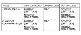
- FIG. 4 is a diagram showing the correlation between the lateral jerk of the vehicle and the rate of change in curvature, and curve entry and curve exit; It is a figure explaining curvature when the data of the lane center line ahead are known.
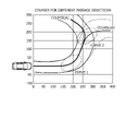
- Fig. 3 shows a compound course (A), (B) comprising two curves;
- FIG. 6 is a diagram showing an out-in outline for course (A) of FIG. 5;
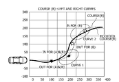
- FIG. 6 is a diagram showing an out-in outline for course (B) of FIG. 5;
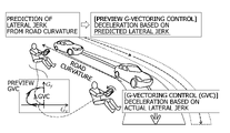
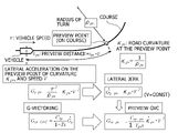
- FIG. 4 is a diagram showing the concept of Preview G-Vectoring control;
- FIG. 1 shows a compound course (A), (B) comprising two curves;
- FIG. 6 is a diagram showing an out-in outline for course (A) of FIG. 5;
- FIG. 6 is a diagram showing an out-in outline for course (B) of FIG. 5;
- FIG. 4 is a diagram showing the concept of Preview G-Vectoring control;
- FIG. 2 is a conceptual diagram of an acceleration/deceleration model based on time change of road curvature
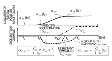
- FIG. 10 is a diagram showing deceleration from before entering a curve, showing temporal changes in preview points.
- FIG. FIG. 4 is a diagram showing deceleration from before entering a curve, showing the correlation between the curvature at the preview point and the deceleration command.
- FIG. 4 is a diagram showing deceleration before entering a curve, and is a diagram showing the correlation between longitudinal acceleration and lateral acceleration.
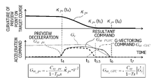
- FIG. 10 is a diagram showing acceleration from before exiting a curve, showing temporal changes in preview points;
- FIG. 10 is a diagram showing acceleration before exiting a curve, and showing a correlation between curvature at a preview point and an acceleration command;
- FIG. 4 is a diagram showing acceleration before exiting a curve, and is a diagram showing the correlation between longitudinal acceleration and lateral acceleration.
- FIG. 4 is a diagram showing a correlation between an offset command value from a lane center line and an acceleration/deceleration command;
- FIG. 10 is a diagram showing the offset at the left curve, and showing the offset from the own vehicle position before entering the left curve. It is a figure which shows the offset in a left curve, Comprising: It is a figure which shows the point information of a lane center line.
- FIG. 4 is a diagram showing an offset from the own vehicle position before entering a right curve; FIG.
- FIG. 10 is a diagram showing a method of generating a corrected target trajectory based on an offset amount; It is a figure which shows the calculation method in the case of making offset amount into the offset amount of curvature.
- FIG. 4 is a diagram showing an example of generating a target trajectory by calculating an offset amount for a circuit track type course; 14 is a diagram showing an example of generating a target trajectory by calculating an offset amount for a circuit track type course using Equation 14.
- FIG. It is a figure which shows the result of having calculated the target track
- FIG. 7B is a diagram showing a result of calculating a target trajectory by applying the calculation method of the second embodiment to the course (B) shown in FIG. 6B;
- FIG. 10 is a diagram showing calculation results of the target trajectory when the distance to the preview point is changed for a complicated course;
- FIG. 10 is a diagram showing calculation results of a target trajectory when offset gains are changed for a complicated course;
- 1 is a conceptual diagram showing a control device and a vehicle using the target trajectory calculation method of the present invention;
- the present invention provides a target trajectory that is offset from the lane or the center of a drivable area, more specifically, a target trajectory that realizes an out-in-outline similar to the case where an expert driver steers. , is provided with a function of calculating continuously.
- Ride comfort does not refer to vertical vibrations caused by uneven road surfaces, but to the ride comfort in response to the vehicle motion generated by driving operations that were conventionally performed by the driver. This can be regarded as comfortable automated driving.
- the ride comfort is not necessarily improved.
- the lateral acceleration of a vehicle turning at a certain speed is determined by the vehicle track, and the longitudinal acceleration is determined by acceleration/deceleration commands.
- the ride comfort is a complex combination of these factors, when driving in the center of the lane at the same speed, the ride comfort is substantially the same.
- the ride comfort can be improved by determining the ideal target trajectory within the allowable range and the speed at which the target trajectory is traced from the road shape, more specifically, the width of the road and the coordinates of the center of the lane.
- lane center coordinates (in other words, lane center line) is not always ideal.
- Japanese Patent Application Laid-Open No. 2014-218098 discloses a drivable area detection device for detecting a drivable area of a vehicle, and a drivable area detected by the drivable area detection apparatus so that the vehicle can travel.
- a driving support device includes a travel control device that executes trajectory control based on a target trajectory that is determined by the vehicle, and a control device that generates the target trajectory.
- the control device is located ahead in the traveling direction from the own vehicle position of the vehicle by a look-ahead distance set according to the vehicle speed of the vehicle.
- the road center of the curve is determined as a reference point.
- control device determines, as a target point, a position offset toward the inside of the curve from the reference point by a lateral displacement set according to the radius of curvature of the curve at the reference point, and determines the position of the vehicle as the target point.
- the target trajectory is generated so as to pass through the target point.
- Japanese Patent Application Laid-Open No. 2019-189187 discloses a travel trajectory design method and a vehicle motion control device that perform route generation equivalent to that of an expert driver.
- Japanese Patent Laid-Open No. 2011-203240 discloses a method of updating the map data from the actual traveling trajectory data, but the actual traveling trajectory depends on the driver's steering, and it is difficult to improve the ride comfort. There is no guarantee that it will be suitable.
- Japanese Patent Laid-Open No. 2011-203240 describes that a correction value is set for each curve direction in response to the out-in-out driving tendency, but how is it specifically defined? is out-in-out, and the specific calculation method of how to determine it is not clear.
- the road center of the curve located ahead in the direction of travel is determined as a reference point, and the lateral acceleration is set according to the radius of curvature of the curve at the reference point.
- a target point is set at a position offset toward the inside of the curve from the reference point by the amount of displacement.
- this method of setting the target point does not offset the target point to the outside of the curve, that is, in the out direction, so it is not a method that can implement the out-in-out theory.
- the traveling trajectory design method of JP-A-2019-189187 it is possible to set a transition curve that accompanies acceleration and deceleration. It is not possible to calculate the target trajectory data to approach from the outside instead of the center. Therefore, the present invention calculates the offset from the center of the lane using the coordinates of the center of the route, for example, the coordinate point information of the center of the lane, and adds or subtracts it to the median value, thereby realizing an out-in-outline target.
- the object is to obtain a trajectory, and to improve the ride comfort and dynamic performance of an automatic driving vehicle following the target trajectory.
- the center line coordinate point data indicating the center of the driving lane or the driving area which is stored or based on the result of measurement, is used to calculate the curvature at an arbitrary point. and the curvature at the point located ahead thereof, the amount of offset from the lane centerline for an arbitrary point is calculated, and the target trajectory offset from the centerline coordinates is continuously calculated.
- the curvature ⁇ pv of that preview point and The offset amount is obtained by dividing the difference from the current curvature ⁇ ve of the lane center point by the distance Lpv, and multiplying it by at least the traveling speed V and the gain Co0.
- the target position is shifted from the origin (point O) of the lane center line in the direction opposite to the turning center of the curve (in other words, out side) or in the direction of the turning center of the curve (in other words, in side). (in other words, target trajectory or target point).
- the distance Lpv to the preview point is given as the product of the vehicle speed V and the preview time tpv.
- the route generation in the present invention is for geometrical things fixed to the absolute coordinate system such as road design, that is, not for macro routes such as movement from point A to point B, but It allows you to set the line on which the vehicle will travel, with a certain degree of freedom within the width of the road.
- the longitudinal acceleration is positive in the forward direction of the vehicle.
- the lateral acceleration when the vehicle is traveling forward, the lateral acceleration generated when turning counterclockwise (in other words, counterclockwise) is positive, and the reverse direction is negative.
- the counterclockwise turning radius is positive, the clockwise turning radius is negative, and the reciprocal of the turning radius is the curvature.
- the counterclockwise turning radius is positive, the clockwise turning radius is negative, and the reciprocal of the turning radius is the curvature.
- Transition curves and out-in-out When a vehicle makes a direct transition from a straight section to a curved section, the ride quality may be affected by abrupt steering requests or a sudden large centrifugal force (or lateral acceleration). and safety are adversely affected, and sudden transitions into curved sections with small radii of curvature have a greater impact. Therefore, a transition curve, which is a curve that gradually changes from a straight line to a predetermined arcuate curvature, may be inserted in the route alignment.
- FIG. 1 shows an example in which a straight section and an arc curve section are connected by a transition curve section.
- the radius ⁇ of the arc curve section is assumed to be 250 m.
- the actual lane has the road width on the left and right with the curve in FIG. 1 as the lane center line.
- the radius ⁇ [m] of the straight section can be regarded as infinite.
- the curvature ⁇ [1/m] is the reciprocal of the turning radius ⁇ [m], as shown in Equation 1. Therefore, when the turning radius ⁇ gradually decreases as the transition curve section is traced, the curvature ⁇ gradually increases.
- the curvature ⁇ is represented by an arc length parameter s[m] representing a unit length.
- Figure 2 shows the correlation between the arc length parameter s and the curvature ⁇ . It shows how it decreases at the time of escape.
- FIG. 2 shows two types of transition curves, a clothoid curve and a sine half-wave diminishing curve.
- the clothoid curve corresponds to the trajectory when the driver operates the steering wheel at a constant speed while the vehicle is traveling at a constant speed.
- the clothoid coefficient C is determined when designing the road shape. Further, in the case of the clothoid curve, the lateral jerk is constant.
- Equation (5) the vehicle lateral jerk J yVC during transition curve running.
- the arc length parameter s that increases per second is V0
- the vehicle lateral jerk JyVC is obtained by differentiating the curvature ⁇ by the relaxation curve length. is a coefficient, and the coefficient is multiplied by the cube of the speed V0.
- the curvature ⁇ handled in the present invention is a signed curvature, where the curvature ⁇ of the left curve is positive and the curvature ⁇ of the right curve is negative.
- FIG. 3 shows the positive/negative of the rate of change of lateral jerk and curvature when entering a curve, running a curve, and exiting a curve, respectively, for a left curve and a right curve. For example, when the vehicle is traveling on a left curve, if a positive lateral jerk is taken when entering the curve, a negative lateral jerk is taken when exiting the curve.
- the rate of change of the curvature ⁇ is positive when entering the curve and negative when exiting the curve.
- the positive and negative values of the lateral jerk and the rate of change of curvature are indicators of curve entry and curve exit. indicates that it is time to exit the curve.
- a vehicle control device that controls automatic driving of a vehicle can grasp entering and exiting a curve by acquiring measured values of lateral jerk. For example, it is possible to predict and calculate the curvature of the lane ahead of the vehicle.
- FIG. 4 shows the curvature prediction calculation when the forward lane centerline data is known.
- Equation 7 is obtained from these values.
- Equation 8 the path curvature ⁇ [i] at each sample point is obtained with reference to Document 1, it becomes as shown in Equation 8.
- the turning radius ⁇ [i] at this instant is obtained from Equation (9).
- the vehicle control device can predict the curvature in front of the vehicle if the coordinates in front of the vehicle are stored as, for example, map data.
- the vehicle control device measures the area in front of the vehicle, for example, from an image captured by a camera mounted on the vehicle, and extracts the central portion of the travel road within which the vehicle can travel, such as the center of the lane, as coordinate data. If possible, the curvature of the path ahead of the vehicle can be predicted.
- the vehicle control device can predict curve entry, steady turning, and curve exit, which the vehicle will travel ahead, based on the relationship shown in FIG.
- the information that the vehicle control device can use to realize out-in-out is speed information and curvature information of the vehicle.
- the amount by which the target position is offset across the width of the road must be determined.
- the lane center line is a virtual line that is drawn along the widthwise center of the road on which the vehicle travels, that is, the lane or the area in which the vehicle can travel.
- the concepts that exist for one curve are three phases: curve entry, curve turning, and curve exit.
- the curve turning phase is steady circular turning. Another possible reason for the need for an offset from the lane center line to achieve out-in-out is to deal with transient situations.
- out-in-out it is necessary to consider the offset for two phases, when entering the curve and exiting the curve.
- out-in is a concept that accompanies a normal curve, and depending on the state of the next curve It depends on whether you swell to the outside or keep the inside.
- FIG. 5 illustrates two courses (A) and (B) that curve differently.
- Course (A) and course (B) shown in FIG. 5 show the center line of the traveling road, that is, the lane center line, and road width margins exist on the left and right of the lane center line, and the offset of the target trajectory is within the range of the margins. , that is, within a range in which the vehicle does not deviate from the road width.
- the first half of course (A) and course (B) are the same curve section (1) that turns left, then in curve section (2), course (A) turns further left and course (B) turns right. It is set to a curved course.
- FIG. 6A shows an out-in outline for course (A) of FIG. 5, and FIG. 6B shows an out-in outline for course (B) of FIG.
- the dotted line represents the lane centerline
- the solid line represents the out-in outline when an expert driver steers.
- the arrows indicate the direction of offset from the lane center line.
- both courses (A) and (B) curve to the left, so the out-in-outline takes a position on the right side of the course before curve section (1).
- In 1) take the left side of the course, that is, the inside.
- the curve section (2) of the course (A) is a left curve, the outside as an offset when entering the curve section (2) is the right direction with respect to the center of the lane.
- the cornering line called out-in-out can be regarded as a combination of two offsets for each curve: out when entering a curve and in when turning a curve. is sometimes out-in-out and sometimes out-in-in. Furthermore, in the out-in-outline, the out as the first offset is done before the curve, the in as the next offset is done before the curve ends, and the out side offset from before the curve entry. and calculate the inside offset before exiting the curve.
- Acceleration/deceleration control linked to lateral motion (G-Vectoring) Acceleration/deceleration control linked to lateral motion automatically accelerates and decelerates in conjunction with lateral motion due to steering operation, thereby generating load transfer between the front and rear wheels to improve vehicle maneuverability and stability. It is a method for Formula 10 is a formula for calculating the longitudinal acceleration command value Gxc, which is the acceleration/deceleration command value in the acceleration/deceleration control linked to lateral motion. The value is given with a first-order lag.
- Gy is the vehicle lateral acceleration
- Gy_dot is the vehicle lateral jerk, that is, the first order differential value of the acceleration
- Cxy is the gain
- T is the first order lag time constant
- s is the Laplace operator
- Gx_DC is the degree not linked to the lateral motion. It is a speed command. Acceleration/deceleration control linked to lateral motion can simulate a part of the lateral and longitudinal motion coordinated control strategy of an expert driver, and it has been confirmed that improved vehicle maneuverability and stability can be achieved .
- the acceleration/deceleration command Gx_DC that is not linked to the lateral motion in Equation 10 is a deceleration component that is not linked to the lateral motion, and is necessary when there is a predictive deceleration when there is a curve ahead or when there is a section speed command. term.
- the sgn (signum) term in Expression 10 is a term provided so that the above operation can be obtained in both the right curve and the left curve. Then, the longitudinal acceleration command value Gxc realizes the operation of decelerating at the time of turn-in at the start of steering, stopping the deceleration because the lateral jerk becomes substantially zero in a steady turn, and accelerating at the time of exiting the curve where the steering return is started. can.
- Equation 10 When the vehicle control device controls the vehicle according to Equation 10, in a "g-g" diagram in which the horizontal axis is the longitudinal acceleration of the vehicle and the vertical axis is the lateral acceleration of the vehicle, the combined acceleration G of the longitudinal acceleration and the lateral acceleration can be expressed as , becomes a motion that transitions curvilinearly with the passage of time, and a control method based on Equation 10 as a control rule is called "G-Vectoring control".
- G-Vectoring control and Preview G-Vectoring control In recent years, an adaptive cruise control system using the Global Positioning System (GPS) and map data has been proposed, and acceleration/deceleration control using GPS has been proposed. It has been put to practical use. Therefore, we added GPS and map data to G-Vectoring control, which used to control only vehicle motion information, and extended it to areas that are not linked to lateral motion, such as deceleration before entering a curve. Preview G-Vectoring control, which is a simple longitudinal acceleration control, has been proposed.
- GPS Global Positioning System
- FIG. 7 shows the concept of Preview G-Vectoring control. While conventional G-Vectoring control performs deceleration control based on the lateral jerk that occurs in the vehicle after entering a curve, Preview G-Vectoring control presumes that the vehicle is affected by the curvature of the road ahead of the vehicle. By obtaining the lateral jerk in advance, deceleration control is performed before entering a curve.
- FIG. 8 is a conceptual diagram of an acceleration/deceleration model based on temporal changes in road curvature.
- a preview point of the travel speed Vpv is set on the course in front of the vehicle at a distance Lpv [m] from the vehicle, and the longitudinal acceleration command value Gxt_pv is calculated based on the time change of the road curvature ⁇ pv at the preview point. to calculate
- Formula 11 shows the basic formula of the acceleration/deceleration model.
- V is the vehicle speed
- Cxy_pv is the gain
- Tpv is the time constant
- ⁇ pv is the road curvature at the preview point
- the "•" symbol on ⁇ pv represents time differentiation.
- the distance Lpv from the own vehicle to the preview point is given as the product of the own vehicle speed V and the preview time tpv.
- the vehicle By generating the longitudinal acceleration based on the longitudinal acceleration command value Gxt_pv obtained by Equation 11, the vehicle can be decelerated before it enters the curve. Further, by combining the longitudinal acceleration command value Gxt_pv obtained by Equation 11 and the longitudinal acceleration command value Gxt_GVC obtained by conventional G-Vectoring control, it is possible to realize longitudinal acceleration control linked to the lateral motion actually occurring in the vehicle. Continuous deceleration control is performed from before entering a curve to steady turning.
- FIG. 9A, 9B, and 9C show deceleration before entering a curve in deceleration control based on Equation 11.
- FIG. 9C is a "gg" diagram in which the horizontal axis is the longitudinal acceleration and the vertical axis is the lateral acceleration.
- the acceleration/deceleration control by G-Vectoring control can be extended to the area before the actual lateral movement of the vehicle. It is possible to decelerate before entering the curve.
- the longitudinal acceleration command value Gxt_pv is given in proportion to the time change of the road curvature, even if the curve is the same, when the speed is high, the curvature of the road changes abruptly, resulting in strong deceleration. weak deceleration.
- the longitudinal acceleration command value Gxt_PGVC can be created by Preview G-Vectoring control as shown in FIGS. 9A, 9B, and 9C.
- FIGS. 10A, 10B, and 10C show how the vehicle exits from a curve.
- FIG. 10C is a "gg" diagram in which the horizontal axis is the longitudinal acceleration and the vertical axis is the lateral acceleration.
- the preview point has left the curve, so the road curvature ⁇ pv at the preview point decreases. Therefore, at time t5, the time change of the road curvature ⁇ pv becomes negative, and a positive longitudinal acceleration command value Gxt_pv is calculated.
- the longitudinal acceleration command value Gxt_pv and the longitudinal acceleration command value Gxt_GVC have a high affinity, and by combining them, as shown in FIG. can be created. Then, an acceleration change is realized such that the resultant acceleration is vectored (see FIG. 10C) so as to go around the "gg" diagram, which is said to give a good driver feeling.
- the offset amount calculation method (vehicle control method, target trajectory calculation method) for realizing out-in-outline with reference to the Preview G-Vectoring control described above, that is, the vehicle control device according to the present invention, the vehicle Embodiments of a control method, a target trajectory calculation method, and a vehicle will be described in detail.
- the out-side offset is calculated before entering the curve, and the in-side offset is calculated before exiting the curve. There is a need.
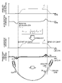
- FIG. 11 is a diagram showing the correlation among vehicle lateral acceleration, acceleration/deceleration command value, curvature, and offset command value during Preview G-Vectoring control.
- FIG. 11 represents the concept of generating deceleration before lateral acceleration and generating acceleration before lateral acceleration decreases.
- the horizontal axis of the graph showing changes in vehicle lateral acceleration and acceleration/deceleration command value is time.
- the curvature is the curvature at the vehicle running point
- the horizontal axis of the graph showing the change in curvature is the arc length parameter.
- the offset command value is a command for the amount of offset from the lane center line
- the horizontal axis of the graph showing changes in the offset command value is the arc length parameter.
- Equation 4 when the running speed is substantially constant, as shown in Equation 4, the lateral acceleration and the curvature have substantially the same profile. Also, as the curvature graph shows, where the curve begins and ends can be expressed by the arc length parameter value.
- the offset command value shown in FIG. 11 is the amount of offset from the lane center line, and is a value that refers to the acceleration/deceleration command value of Preview G-Vectoring.
- Preview G-Vectoring control is generating a deceleration command
- a signal with approximately the same profile as the deceleration command value is used as the offset command value on the out side
- Preview G-Vectoring control is generating an acceleration command.
- a signal with approximately the same profile as the acceleration command is used as the in-side offset command value.
- FIG. 11 shows the correlation between the target trajectory based on the offset command value and the lane center line.
- the target trajectory shown in this figure is out-in (-out) such that the vehicle bulges outward (out) when entering a curve and cuts inward (inward) when exiting the curve.
- the basic concept of the method of calculating the offset from the lane center line of the present invention is to increase the absolute value of the curvature change using the curvature change information at points ahead of the point where the offset should be calculated. If it is, the offset amount to the out side (turning outer side) in the direction opposite to the sign of the curvature is calculated. In other words, if the curvature at a point ahead of the point at which the offset should be calculated increases to the left, the amount of offset to the right is calculated, and the curvature at the point ahead of the point at which the offset is to be calculated increases to the right. If it increases in the left direction, the offset amount is obtained in the left direction. On the other hand, when the absolute value of the curvature change is decreasing, the offset amount to the in side (turning inner side) in the same direction as the sign of the curvature is calculated.
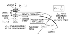
- FIG. 12A is a diagram showing the vehicle position on the lane center line [xve, yve], the preview point on the lane center line [xpv, ypv], and the offset from the vehicle position; Indicates information (waypoint data).
- the various types of data described above are stored for each sample point as lane center line point information (see FIG. 12B).
- the point information of the lane center line described above is used to calculate the offset amount d(i) for each point (in other words, each sample point), and to realize out-in-out.
- the target position is corrected, and the corrected target trajectory is determined from the new point sequence data X(i), Y(i), that is, the lane center line.
- vehicle position is used below, this is a notation for convenience, and the following method can be calculated off-line if point information of the lane center line is available. However, in the off-line case, since the calculation is performed assuming that the speed is constant, it is necessary to calculate in advance the target trajectory corrected from the center of the lane for a plurality of speed ranges.
- the vehicle control device stores in advance the target trajectory corrected from the pre-calculated lane center line as map data, and can control the autonomous vehicle to follow the trajectory.
- the vehicle control device may correct the lane center line in front of the vehicle and calculate the target trajectory at any time while the vehicle is traveling in automatic driving mode, and may control the actuator so that the target trajectory is traced on the target trajectory. can.
- the offset amount dve for each point on the lane center line is obtained according to Equation 13 with reference to Preview G-Vectoring control and omitting first-order lag elements and the like.
- the amount of offset from the lane center line is determined according to the time change of the curvature at the preview point located in front of the vehicle position, in other words, the physical quantity related to the time change of the front curvature of the road on which the vehicle is traveling. , which is the basic idea of the present invention.
- C O0 in Equation 13 is the gain of the offset amount with respect to the time change of the curvature, and in setting this gain C O0 , even if the time change of the curvature is the maximum value, the target position does not exceed the road width due to the offset. It is necessary to consider such as Also, the change in curvature over time is the product of the change in arc length parameter over time (ds/dt) and the change in curvature with respect to the change in arc length parameter (d ⁇ /dt).
- the offset amount dve at the vehicle position is the rightmost side of Equation (13).
- the offset amount dve can be determined for each speed from the location information search result in FIG. 12B.
- Equation 14 when the azimuth angle (angle with respect to the X-axis) of the lane center line in the fixed coordinate system O-XY is ⁇ (i) and the offset amount is d(i), the vehicle position [x0(i ), y0(i)] to the corrected target point [X(i), Y(i)] is given by Equation 14.
- the azimuth angle ⁇ (i) is a physical quantity relating to the azimuth angle of the reference line on the traveling road with respect to a preset fixed coordinate system.
- the method of analytically calculating the offset amount using the point information of the lane center line and calculating the target point [X(i), Y(i)] constituting the target trajectory has been disclosed.
- the above-described target trajectory calculation method offsets the lane center line in the width direction of the traveling road based on the physical quantity related to the time change of the forward curvature and the physical quantity related to the azimuth angle of the lane center line (reference line). A target position is obtained.
- the target trajectory after correction is determined in the form of a displacement offset with respect to the coordinate points.
- the target trajectory after correction can be determined as a curvature offset amount as follows.
- the curvature offset ⁇ dve is obtained according to Equation 15.
- FIG. 15 shows a specific calculation method of the corrected target trajectory in the method of determining the target trajectory using the curvature offset ⁇ dve.
- Equation 16 is obtained.
- the vehicle position is The conversion formula from [x0(i), y0(i)] to the corrected target point [X(i), Y(i)] is given by Equation 18.
- the conversion formula of formula 14 and the conversion formula of formula 18 basically include the same information, but in formula 14 the offset amount is obtained as a coordinate difference, and in formula 18 the offset amount is obtained as a curvature difference. In either case, the offset amount is calculated based on the information on the curvature change of the lane center line ahead, and by adding or subtracting the offset amount from the lane center line, the out-in (out) target trajectory can be analytically determined. can be calculated.
- the target trajectory calculation method according to the present invention and the control device, control method, and vehicle using the calculation method, have at least two A coordinate value or curvature offset amount is calculated for each orbital coordinate data based on basic orbital coordinate data which is a part or all of a dimensional coordinate value, a orbital curvature, and an orbital azimuth, and the orbital coordinate data
- the present invention is characterized in that an offset amount is added to each track, new target trajectory coordinate data is constructed, and the trajectory of the vehicle is controlled based on the target trajectory coordinate data.
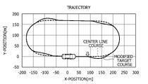
- FIG. 16 shows an example of generating a target trajectory by calculating an offset amount based on point information of a lane center line using the present invention in a circuit track type course. Note that in FIG. 16, the target trajectory appears discontinuous because the offset gain is set to a large value in order to make the corrected target trajectory easier to see.
- the offset amount is calculated from the points indicated by the arrows in FIG. 16, and the target trajectory bulges out. After that, since the offset amount becomes zero, a target trajectory that returns to the lane center line is generated.
- a first preview point indicated by an arrow in FIG. 16 is a straight road before the beginning of the transition curve, and the curvature changes with time is zero. However, since the absolute value of the change in curvature over time at the second preview point located on the course ahead of the first preview point increases, suggesting a curve entrance, the change in curvature over time is zero. From time to time, a target position offset to the out side with respect to the lane center line is set. In other words, an offset amount is obtained in the right or left direction with respect to the first preview point.
- the route to cut inward early is also reproduced.
- the target trajectory returns to above the lane center line, the target trajectory swells to the outside side in preparation for entering the next curve, returns to the lane center line when driving the curve, and then the target trajectory that cuts into the inside side early is generated. ing.
- the target is offset to the inside of the lane center line, that is, to the inside of the turn. Position is set.
- FIG. 16 shows the target trajectory when the coordinate difference is used as the offset, similar results can be obtained when the offset is used as the curvature difference.
- Preview G-Vectoring control provides a deceleration command (equivalent to the above-mentioned offset amount) created based on the rate of change of the front curvature, and a deceleration command proportional to the lateral jerk that occurs when the vehicle runs on a transition curve. Use them in combination. That is, the Preview G-Vectoring control uses a combination of components derived from forward information and components based on current information for control.
- Equation 19 When the conversion as in Equation 19 is performed, the calculation becomes simple, and forward curvature information and current curvature information can be explicitly added to the calculation formula of the offset amount dve. Furthermore, according to Equation 19, it can be seen that the offset amount dve increases as the speed V increases.
- the offset amount of the first basic trajectory coordinate data having a smaller arc length from the origin is at least the information of the second basic trajectory coordinate data having a longer arc length than the first trajectory coordinate. It is clear that it is calculated using In other words, according to Equation 19, the first curvature at the first preview point ahead of the travel path containing the vehicle position and the second preview point ahead of the first preview point ahead of the travel path It is possible to obtain a physical quantity related to the time change of the curvature from the difference between the second curvature at , and obtain the offset amount at the first preview point based on the time change of the curvature.
- the amount of offset is obtained based on the physical quantity relating to the temporal change in the curvature of the road ahead of the position where the amount of offset in front of the road is to be obtained.
- the target trajectory calculation method of the present invention when the amount of change in the trajectory curvature with respect to the data before and after the second basic trajectory coordinate data increases in the left direction, If the coordinate value offset of is directed to the right, or if the curvature offset of the first orbital coordinate is directed to the right and increases to the right, the coordinate value offset to the normal direction of the first orbital coordinate is directed to the left. Alternatively, the curvature offset of the first trajectory coordinate is set to the left.
- the signed trajectory curvature with positive leftward bending of the second basic trajectory coordinate data is ⁇ pv
- the leftward bending of the first basic trajectory coordinate data is ⁇ pv.
- the difference .DELTA..kappa make the orbital coordinate curvature offset in the negative direction.
- the coordinate value offset in the normal direction of the first orbital coordinate is set to the left in proportion to the value obtained by multiplying the difference ⁇ by a positive gain C 0 , or the first Orbital coordinate curvature offset in the positive direction.
- Equation 14 is used to calculate the actual corrected coordinates, in other words, the target point after correction.
- FIG. 17 shows an example of generating a target trajectory in a circuit track type course by calculating an offset amount according to Equation 14 using point information on the lane center line, as in FIG. 16 .
- the offset gain is set to a large value so that the corrected target trajectory can be easily seen.
- the distance Lpv is set to 100 [m]
- the offset amount is calculated using the curvature information of the lane center line 100 m ahead and the current curvature information of the lane center line.
- the course in FIG. 17 starts from the origin of the XY coordinates, as in FIG.
- the course follows an arc with a radius of 80m.
- the offset amount is calculated from the point indicated by the arrow in the figure (100m before the transition curve starts), and the target trajectory is swollen to the outside. After that, since the offset amount becomes zero, a target trajectory that returns to the lane center line is generated.
- correction starts when the signed trajectory curvature, which is positive for the leftward turn in the first basic trajectory coordinate data, is zero. Also, at the end of the curve, the route to cut inward early is also reproduced. After that, the target trajectory returns to the lane center line, the target trajectory swells to the outside side in preparation for the next curve, the target trajectory returns to the lane center line when driving the curve, and then the target trajectory that cuts to the inside side is generated. ing.
- the target trajectory in FIG. 17 is smoother than the target trajectory in FIG. 16, and it is possible to reproduce a situation in which the vehicle is offset from before the curve to the outside in advance, as done by an expert driver.
- FIG. 17 shows the target trajectory when the coordinate difference is used as the offset, the same result can be obtained when the offset is used as the curvature difference.
- FIG. 17 shows that out-in (.out) target trajectories are obtained by the present invention for lane centerline data that continuously curve in the same direction.
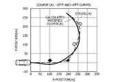
- the solid line in FIG. 18A is the result of calculating the target trajectory using Equation 19 for such a course (A).
- the target trajectory for entering the curve from the right side in other words, the outside side
- Such a target trajectory is qualitatively consistent with the out-in-out (in) line that an expert driver would take.
- the course (B) is a course in which, after passing through the first left curve, it turns around and enters the next right curve (dotted line in FIG. 18B).
- the solid line in FIG. 18B is the result of calculating the target trajectory for such a course (B) using Equation 19, and operations such as parameters and sign switching are not performed.
- the target trajectory has been calculated to approach the first curve from the right (outside) and enter the second curve from the left (outside). .
- Such a target trajectory is qualitatively consistent with the out-in-out (in) line that an expert driver would take.
- the lane center line From this data, it was verified that the out-in-out (in) line that an expert driver would take could be qualitatively reproduced. In addition, the expert driver's line taking, which was said to be out-in-out, is actually only out-in for one curve. was found to have been determined.
- FIGS. 19 and 20 show how the target trajectory calculation method according to the present invention handles complicated courses. From FIGS. 19 and 20, it can be confirmed that the trajectory that an expert driver would take, such as out-in-out, shortcuts at continuous curves, etc., can be reproduced.
- FIG. 19 shows a comparison between a case where the distance Lpv from the vehicle position to the preview point is 50 m and a case where it is 100 m.
- the distance Lpv is lengthened, an offset from the near side in the out or in direction occurs. Therefore, it is necessary to set the optimum distance Lpv according to conditions such as course shape and vehicle speed. Clearly it can be done.
- the distance Lpv is 100 m
- the nominal value of the product Co ⁇ V of the gain Co and the vehicle speed V (simply referred to as Gain in the figure) is 1
- the gains are multiplied by 5 and 10, respectively.
- the gain Co it is also necessary to set an optimum value according to conditions such as the course shape and vehicle speed. It is clear that it can be reproduced.
- variable gains i.e., different gains on the out side and in sides
- various settings such as the vehicle speed V to the square or cube are possible.
- tuning of the target trajectory calculation method according to the present invention it is possible to change parameters such as the distance Lpv and the gain Co according to the intention of the driver/passenger.
- FIG. 21 is a concept showing a vehicle control system including a vehicle control device that is a control device that executes the target trajectory calculation method according to the present invention, that is, a vehicle control system that executes the vehicle control method according to the present invention, and a vehicle. It is a diagram.
- a vehicle control system 200 mounted on the vehicle 100 has an external world recognition section 300 , a driving state detection section 400 , a vehicle control device 500 , a braking device 600 , a drive device 700 and a steering device 800 .
- the external world recognition unit 300 has an external world detection device such as a laser scanning device, a camera, a millimeter wave radar, and a GPS receiver, and acquires external world information in front of the road on which the vehicle 100 travels.
- the external world information includes information such as white lines related to the road on which the vehicle 100 travels, as well as information such as surrounding moving objects and static objects such as obstacles.
- the driving state detection unit 400 is composed of a plurality of sensors that detect the driving state of the vehicle 100.
- the wheel speed sensor detects the rotation speed of each wheel 100FL, 100FR, 100RL, and 100RR of the vehicle 100, and the longitudinal acceleration of the vehicle 100.
- an acceleration sensor for detecting lateral acceleration and the like. Note that the speed of the vehicle 100 can be estimated based on the rotational speed of each wheel detected by the wheel speed sensor.
- Vehicle control device 500 is an AD (Autonomous Driving)/ADAS (Advanced driver-assistance systems) controller of vehicle 100 .
- the vehicle control device 500 is an electronic control device mainly composed of a microcomputer (in other words, a control section or a control unit) that performs calculations based on input information and outputs calculation results. It includes an MPU (Microprocessor Unit), a ROM (Read Only Memory), a RAM (Random Access Memory), and the like.
- MPU Microprocessor Unit
- ROM Read Only Memory
- RAM Random Access Memory
- Braking device 600 is a device capable of electronically controlling the braking force of vehicle 100, such as an electronically controlled electro-hydraulic brake provided with an actuator that generates hydraulic pressure.
- Drive device 700 is an internal combustion engine, an electric motor, or the like that generates driving force for vehicle 100 , and is a device capable of electronically controlling the driving force for vehicle 100 .
- the steering device 800 is a device such as an electric power steering device or a steer-by-wire system that can electronically control the steered wheels of the vehicle 100, more specifically, the steering angles of the front wheels 100FL and 100FR by a steering actuator such as an electric motor.
- the vehicle control device 500 acquires various types of information from the external world recognition unit 300 and the driving state detection unit 400, and uses the above-described method of continuously calculating the offset amount using the curvature change information of the lane center line ahead.
- a target trajectory (in other words, target position) is generated.
- the vehicle control device 500 obtains a command relating to the motion of the vehicle 100 so that the vehicle 100 travels along the generated target trajectory at the set speed, and the braking device 600, which is an actuator that controls the motion of the vehicle 10, and the driving device. 700, to output a control command to the steering device 800;
- the vehicle control device 500 can be used even in a situation where the vehicle needs to make a turn with a large steering angle, when other vehicles or pedestrians suddenly jump out, or when a sharp turn is necessary to avoid falling objects on the road.
- a target trajectory is generated according to the information sensed by the external world recognition unit 300, and a control command is output so that the vehicle follows the target trajectory.
- the vehicle control device 500 does not immediately use the forward sensing information or the lane center line point information as it is, but temporarily stores it in an internal memory, calculates the offset amount, corrects it, and then uses it.
- a point from to the present can be recognized as a line (in other words, a trajectory), and such a configuration makes it possible to follow a target trajectory with high accuracy.
- the vehicle control device 500 can predict the responses of the actuators and the vehicle by performing a prediction simulation of the vehicle motion, correct the response delay, and further improve the accuracy of the trajectory following.
- the vehicle control device 500 calculates the offset from the center using the coordinate point information of the center of the route, for example, the coordinate point information of the center of the lane, and adds or subtracts it to the median value. It is possible to obtain a target trajectory that realizes out-in-outline, and improve ride comfort and maneuverability in automatic driving that follows the target trajectory.
- the embodiment of the present invention has been described assuming automatic driving (AD: Autonomous Driving). -assistance systems), the above target trajectory calculation method can be applied. In this case, the quality of warnings and interventions can be improved by judging straying and lane keeping based on out-in-outline in addition to the lane center.
- AD Autonomous Driving
- the reference line of the traveling road is the lane center line, but the reference line is not limited to the lane center line, and the present invention can be applied to any curved line as the reference line. is applicable.
- SYMBOLS 100... Vehicle 200... Vehicle control system 300... External recognition part 400... Driving state detection part 500... Vehicle control apparatus (AD/ADAS controller) 600... Braking apparatus 700... Driving apparatus 800... Steering apparatus
Landscapes
- Engineering & Computer Science (AREA)
- Transportation (AREA)
- Mechanical Engineering (AREA)
- Automation & Control Theory (AREA)
- Human Computer Interaction (AREA)
- Chemical & Material Sciences (AREA)
- Combustion & Propulsion (AREA)
- Control Of Driving Devices And Active Controlling Of Vehicle (AREA)
Abstract
Description
そして、特許文献1の道路形状学習装置では、アウト・イン・アウトの走行傾向に対応してカーブ方向毎の補正値を設定することにより、処理の複雑化を招くことなく容易に道路の形状を学習することができる。
なお、本発明は、車両の自動運転において、車線或いは走行可能なエリアの中央からオフセットした目標軌道、詳細には、エキスパートドライバが操舵する場合と同様なアウト・イン・アウトラインを実現した目標軌道を、連続的に算出する機能を備えることを特徴とする。
また、自動運転の公道実証実験も各種行われているが、センサ情報に基づいて車線の中央を走り続けるという技術の検証に留まっている。
ここでの乗り心地とは、路面凹凸による上下振動などではなく、従来ドライバが行っていた運転操作によって発生する車両運動に対する乗り心地のことであり、エキスパートドライバが運転したときの車両運動を実現することが、乗り心地のよい自動運転と見做すことができる。
ある速度で旋回する車両の横加速度は車両軌道で決まり、前後加速度は加減速指令で決まり、これに伴って、車体ばね上姿勢であるロール運動、ピッチ運動が発生する。
つまり、許される範囲内での理想的な目標軌道、目標軌道を辿る速度を、道路形状、詳細には、道路の幅、車線中央の座標から決定することにより、乗り心地を向上することができ、車線中央座標(換言すれば、車線中央線)を辿ることが必ずしも理想的とは言えない。
例えば、特開2011-203240号公報には、前述したように、アウト・イン・アウトの走行傾向に対応してカーブ方向毎の補正値を設定することにより、処理の複雑化を招くことなく容易に道路の形状を学習することができる、道路形状学習装置が開示されている。
ここで、前記制御装置は、前記車両の進行方向先にカーブが存在する場合、前記車両の自車位置から、前記車両の車両速度に応じて設定される先読み距離分、進行方向先に位置する前記カーブの道路中心を基準点として決定する。
そして、前記制御装置は、前記基準点における前記カーブの曲率半径に応じて設定される横変位分だけ、前記基準点からカーブ内側へオフセットした位置を目標点として決定し、前記自車位置と前記目標点を通るように前記目標軌跡を生成する。
この走行軌道設計方法及び車両運動制御装置は、緩和曲線長を進む速度Vが小さくなるか、単位緩和曲線長sだけ進むのに要する時間t(V=s/t)が大きくなると、曲率κを大きい方向に変化させ、緩和曲線長を進む速度Vが大きくなるか、単位緩和曲線長sだけ進むのに要する時間tが小さくなると、曲率κを大きい方向に変化させる。
また、上記特開2011-203240号公報には、アウト・イン・アウトの走行傾向に対応してカーブ方向毎の補正値を設定するとの記載があるが、具体的にどのように定義されたものがアウト・イン・アウトで、それをどのように決定するのかという、具体的な算出方法が明確ではない。
しかし、係る目標点の設定方法は、カーブ外側、すなわちアウト方向へ目標点をオフセットするものではないから、アウト・イン・アウトというセオリーを実現できる方法ではない。
そこで、本発明は、経路中央の座標、例えば車線の中央の座標点情報を用いて、その車線中央からのオフセットを計算して中央値に加減することにより、アウト・イン・アウトラインを実現した目標軌道を得ることを課題とし、更に、その目標軌道を辿る自動運転車両の乗り心地、運動性能を向上することを課題とする。
また、原点(O点)の車線中央線から、カーブの旋回中心から反対方向(換言すれば、アウト側)或いはカーブの旋回中心の方向(換言すれば、イン側)へずらしたものを目標位置(換言すれば、目標軌道、若しくは、目標点)とする。
なお、プレビューポイントまでの距離Lpvは、自車速度Vとプレビュー時間tpvの積として与えられる。
上記の目標軌道算出方法によれば、カーブ進入前にカーブの曲率変化に応じてアウト側に膨らむ目標軌道とイン側に入り込む目標軌道を算出することができ、この目標軌道を辿るように車両を制御することにより、エキスパートドライバの運転と同様な安全性の向上と乗り心地の向上などの効果を享受することができる。
(1)緩和曲線及びアウト・イン・アウト
(2)横運動に連係した加減速制御(G-Vectoring)
(3)G-Vectoring制御、及び、カーブ進入前の自動減速制御を導入したPreview G-Vectoring制御
を説明する。
以下の説明においては、車両の重心点を原点とし、車両の前後方向をx、x方向に直角な方向(換言すれば、車両の横方向)をyとした場合、x方向の加速度を前後加速度、y方向の加速度を横加速度とする。
また、横加速度は、車両が前方向に進行している際に、左回り(換言すれば、反時計回り)旋回時に発生する横加速度を正とし、逆方向を負とする。
更に、走行路について、左回りの旋回半径を正、右回りの旋回半径を負とし、旋回半径の逆数を曲率とする。同様に、目標軌道に関しても、左回りの旋回半径を正、右回りの旋回半径を負とし、旋回半径の逆数を曲率とする。
車両が直線区間から曲線区間へ直接移行すると、急激な操舵操作を要求されたり、突然大きな遠心力(または横加速度)が作用したりするなど、乗り心地や安全性に悪影響を与え、曲率半径の小さな曲線区間への突然の移行は影響が大きくなる。
そこで、路線線形において、直線から所定の円弧曲線の曲率へ徐々に変化する曲線である緩和曲線を挿入する場合がある。
但し、実際の車線は図1の曲線を車線中央線として、左右に道路幅を持つ。また、直線区間の半径ρ[m]は無限大と見做すことができる。
一方、曲率κ[1/m]は、数式1に示すように、旋回半径ρ[m]の逆数である。

図2は、弧長パラメータsと曲率κとの相関を示し、緩和曲線の曲率κがカーブ進入時に弧長パラメータsに従い増加していき、一定の曲率、つまり、定常円になり、その後、カーブ脱出時に減少していく様態を示す。
また、図2は、クロソイド曲線と、サイン半波長逓減曲線との2つの緩和曲線のタイプを示している。
クロソイド曲線は、弧長パラメータsに対して直線的に曲率κが増加するので、クロソイド係数をCとすると、曲率κは、数式2のように表せる。

なお、クロソイド係数Cは、道路形状の設計時に決定されたとおりのものである。また、クロソイド曲線の場合、横加加速度が一定となる。
サイン半波長逓減曲線は、弧長パラメータsに対して半波長の正弦波状の形状で曲率が増加するので、緩和曲線長をXとし、最終的に半径Rの円弧に接続する場合、曲率κは、数式3のように表せる。

この場合、V0×tTVC=STを満たす時間tTVC後に、車両は定常旋回状態になる。
そして、このときの車両横加速度GyVCは、数式4で表せる。


そして、弧長パラメータsに対して曲率κが増加しない状態になると、車両は横加加速度一定で数式4の横加速度に到達する。
本発明で取り扱う曲率κは、符号付き曲率(signed curvature)で、左カーブの曲率κを正、右カーブの曲率κを負とする。
例えば、車両が左カーブを走行するときで、カーブ進入時に正の横加加速度ととると、カーブ脱出時には負の横加加速度をとることになる。
つまり、横加加速度及び曲率の変化率の正負は、カーブ進入とカーブ脱出とを表す指標となり、例えば、左カーブを走行する場合、横加加速度、曲率変化率が正の場合はカーブ進入時、負の場合はカーブ脱出時であることを示す。
図4は、前方の車線中央線のデータが既知である場合の曲率の予測計算を示す。
但し、各点列データは、数式6に示すように、標本点間距離が1であるとする。



また、車両制御装置は、車両前方を例えば車両に搭載されたカメラの画像などから計測して、自車が走行可能な範囲である走行路の真ん中の部分、たとえば、車線中央を座標データとして抽出することができれば、車両前方の経路曲率を予測することができる。
そして、車両制御装置が、アウト・イン・アウトの実現のために使える情報は、車両の速度情報と曲率情報であり、車両制御装置は、これらの情報から、車線中央線(換言すれば、走行路における基準線)から走行路の幅方向に目標位置をオフセットさせる量を決定しなければならない。
なお、車線中央線とは、車両が走行する走行路、つまり、車線或いは走行可能なエリアの幅方向の中央に沿って引かれた仮想線である。
このうち、カーブ旋回のフェーズは、定常的な円旋回である。
また、アウト・イン・アウトを実現するための車線中央線からのオフセットが必要とされる理由として、過渡的な状況への対応が考えられる。
このように考えると、アウト・イン・アウトというように1つのカーブに3つのオフセットを考えるのではなく、アウト・インが通常の1つのカーブに付随する概念で、次のカーブの様態に応じてアウトに膨れるかインをキープするのかが異なってくる。
図5は、曲がり方が異なる2つのコース(A)、(B)を例示する。
コース(A)とコース(B)の前半は同じ左に曲がるカーブセクション(1)であり、その後、カーブセクション(2)において、コース(A)は更に左に曲がり、コース(B)は右に曲がるコース設定になっている。
図6A及び図6Bにおいて、点線は車線中央線を表し、実線はエキスパートドライバが操舵する場合でのアウト・イン・アウトラインを示す。
また、図6A及び図6Bにおいて、矢印は、それぞれ車線中央線からのオフセットの方向を示している。
次いで、コース(A)のカーブセクション(2)は左カーブであるので、カーブセクション(2)への進入時のオフセットとしての外側は、車線中央に対して右方向となる。
ここで、コース(A)の走行ラインは、カーブセクション(1)の前後においては、アウト・イン・アウトとなっている。
そして、コース(B)のカーブセクション(2)においてコース右側、すなわち車線中央に対して内側にオフセットしたラインを辿る。
ここで、コース(B)の走行ラインは、カーブセクション(1)の前後においては、アウト・イン・インとなっている。
更に、アウト・イン・アウトラインでは、最初のオフセットとしてのアウトは、カーブの前に行われ、次のオフセットとしてのインはカーブが終わる前に行われていて、カーブの進入前からアウト側のオフセットを算出し、カーブの脱出前にイン側のオフセットを算出する必要がある。
横運動に連係した加減速制御は、操舵操作による横運動に連係して自動的に加減速することにより、前輪と後輪の間に荷重移動を発生させて車両の操縦性と安定性の向上を図る方法である。
数式10は、横運動に連係した加減速制御における加減速度指令値である前後加速度指令値Gxcの算出式であり、前後加速度指令値Gxcは、基本的に、横加加速度Gy_dotにゲインCxyを掛け、1次遅れを付与した値とする。
そして、横運動に連係した加減速制御により、エキスパートドライバの横と前後運動の連係制御ストラテジの一部を模擬することができ、車両の操縦性、安定性の向上が実現できることが確認されている。

そして、操舵開始のターンイン時に減速し、定常旋回になると横加加速度が略ゼロとなるので減速を停止し、操舵戻しを開始するカーブ脱出時に加速する動作が、上記の前後加速度指令値Gxcによって実現できる。
近年、全地球測位システム(GPS:Global Positioning System)と地図データを用いたアダプティブクルーズコントロールシステムが提案されており、GPSを使った加減速制御が実用化されている。
そこで、車両の運動情報のみで制御を行っていたG-Vectoring制御に、新たにGPSと地図データを加え、カーブ進入前の減速のような横運動に連係しない領域まで拡張した、違和感の少ない新たな前後加速度制御であるPreview G-Vectoring制御が提案されている。
従来のG-Vectoring制御は、カーブ進入後に車両に発生する横加加速度に基づいて減速制御を実施するのに対し、Preview G-Vectoring制御は、自車前方の道路曲率から車両に発生すると推定される横加加速度を事前に求めることで、カーブ進入前から減速制御を行う。
本モデルでは、自車から距離Lpv[m]だけ離れた自車前方のコース上に移動速度Vpvのプレビューポイントを設定し、プレビューポイントでの道路曲率κpvの時間変化に基づいて前後加速度指令値Gxt_pvを演算する。

また、数式11によって得た前後加速度指令値Gxt_pvと、従来のG-Vectoring制御による前後加速度指令値Gxt_GVCとを組み合わせることで、実際に車両に発生した横運動に連係した前後加速度制御を実現でき、カーブ進入前から定常旋回に至るまで連続した減速制御となる。
プレビューポイントがカーブ進入前である時刻t0からカーブ進入後の時刻t1となった際、プレビューポイントでの道路曲率κpvが増加する。
そのため、道路曲率κpvの時間変化が正となって、負の前後加速度指令値Gxt_pvが演算され、結果、車両はカーブ進入前から減速することになる。
また、前後加速度指令値Gxt_pvを道路曲率の時間変化に比例して与えるため、同じカーブであっても、速度が高い条件では急激に道路曲率が変化することで強い減速となり、速度が低い条件では弱い減速となる。
そのため、前後加速度指令値Gxt_pvと前後加速度指令値Gxt_GVCの親和性は高い。
そして、両者を組み合せることで、図9A、図9B、図9Cに示すように、Preview G-Vectoring制御による前後加速度指令値Gxt_PGVCが作成できる。
その結果、ドライバフィーリングがよいとされる“g-g”ダイアグラム内をまわるような、換言すれば、合成加速度がベクタリングするような、加速度変化が実現される(図9C参照)。
なお、図10Cは、横軸を前後加速度、縦軸を横加速度とする、“g-g”ダイアグラムである。
図10A、図10Bに示すように、車両がまだカーブを走行している時刻t5の状況でも、プレビューポイントがカーブから脱出しているため、プレビューポイントでの道路曲率κpvは減少する。
そのため、時刻t5の時点で道路曲率κpvの時間変化が負となって、正の前後加速度指令値Gxt_pvが演算され、結果、車両は旋回途中から脱出に向けて加速するように制御される。
そして、ドライバフィーリングがよいとされる“g-g”ダイアグラム内をまわるような、換言すれば、合成加速度がベクタリングするような、加速度変化が実現される(図10C参照)。
図6A、図6Bの説明で述べたように、アウト・イン・アウトを実現するためには、カーブの進入前からアウト側のオフセットを算出し、カーブの脱出前にイン側のオフセットを算出する必要がある。
図11は、横加速度が発生する前に減速度を発生させ、横加速度が低下する前に加速度を発生させるという概念を表している。
一方、曲率は、車両走行点での曲率であって、曲率の変化を示すグラフの横軸は弧長パラメータとしてある。
また、オフセット指令値は、車線中央線からのオフセット量の指令であって、オフセット指令値の変化を示すグラフの横軸は弧長パラメータとしてある。
また、曲率のグラフが示すように、どこからカーブが始まり、どこでカーブが終わるかを弧長パラメータ値で表現することができる。
ここでは、Preview G-Vectoring制御が減速指令を発生しているときに、減速指令値と略同プロファイルの信号をアウト側のオフセット指令値とし、Preview G-Vectoring制御が加速指令を発生しているときに、加速指令と略同プロファイルの信号をイン側のオフセット指令値とする。
この図に示す目標軌道は、カーブ進入時に外側(アウト)に膨らみ、カーブ脱出時に内側(イン)に切り込むようなアウト・イン(・アウト)になっている。
つまり、オフセットを計算すべきポイントよりも前方のポイントでの曲率が左方向に増大している場合、右方向にオフセット量を求め、オフセットを計算すべきポイントよりも前方のポイントでの曲率が右方向に増大している場合、左方向にオフセット量を求める。
一方、曲率変化の絶対値が減少しているときには、その曲率の符号と同方向のイン側(旋回内側)へのオフセット量を算出する。
図12Aは、車線中央線上の自車位置[xve, yve]、車線中央線上のプレビューポイント[xpv, ypv]、自車位置からのオフセットを示す図であり、図12Bは、車線中央線上における地点情報(waypoint deta)を示す。
したがって、車線中央線上の自車位置[xve, yve]及び車線中央線上のプレビューポイント[xpv, ypv]は、上記の標本点の中に入っている。
仮に、i=1の点列が座標系の原点であり、i=2の点列を結ぶ直線がx軸上であれば、数式12で、この車線中央線の瞬時毎の方位角を計算することができ、これらの情報も各点毎のデータに加えることができる。

第1実施形態においては、前述した車線中央線の地点情報を用い、各地点(換言すれば、各標本点)に対するオフセット量d(i)を算出し、アウト・イン・アウトを実現するための目標位置の補正を行い、新たな点列データX(i),Y(i)、つまり、車線中央線から補正された目標軌道を決定する。
但し、オフラインの場合、速度一定としての計算となるため、複数の速度域に対して事前に車線中央から補正された目標軌道を計算しておく必要がある。
また、車両制御装置は、自動運転での走行中に、自車両の前方の車線中央線に対して補正を行って目標軌道を随時計算しながら、その上を辿るようにアクチュエータを制御することもできる。
先に述べた通り、Preview G-Vectoring制御の減速指令をアウト側のオフセットとし、加速指令をイン側のオフセットとすることにより、カーブの進入前及び脱出前にオフセットを実現することができる(図11参照)。
上記の曲率κpvの情報は、地点情報に記載される(図12B参照)。

図示を省略したが、左カーブの場合であってプレビューポイントでの曲率変化が負、つまり、左方向の曲率が減少のときは、車両固定座標のy軸の正の方向、換言すれば、左カーブの内側にオフセットの向きを決定する。
図示を省略したが、右カーブの場合であってプレビューポイントでの曲率変化が正、つまり、右方向の曲率が減少のときは、車両固定座標のy軸の負の方向、換言すれば、右カーブの内側にオフセットの向きを決定する。
また、曲率の時間変化は、弧長パラメータの時間変化(ds/dt)と弧長パラメータ変化に対する曲率の変化(dκ/dt)の積となる。
係るオフセット量dveは、図12Bの地点情報の検索結果から速度毎に決定することができる。
図14に示したように、車線中央線の固定座標系O-XYにおける方位角(X軸に対する角度)をθ(i)、オフセット量をd(i)とすると、自車位置[x0(i),y0(i)]から補正後の目標点[X(i),Y(i)]への変換式は、数式14のようになる。

つまり、上記の目標軌道算出方法は、前方の曲率の時間変化に関する物理量と、車線中央線(基準線)の方位角に関する物理量とに基づいて、車線中央線から走行路の幅方向にオフセットさせた目標位置を求めるものである。
曲率オフセットκdveは、数式15にしたがって求められる。

ここで、車線中央線の地点情報が単位弧長毎に記録されているとすると、数式16に示すようになる。



いずれの場合も、前方の車線中央線の曲率変化の情報に基づいてオフセット量を計算し、車線中央線からオフセット量だけ加減算することにより、アウト・イン(・アウト)の目標軌道を解析的に算出することができる。
なお、図16では、補正した目標軌道を見やすくするために、オフセットゲインを大きめの値に設定していることから、目標軌道が不連続に見えている。
図16中に矢印で示したポイントからオフセット量が計算され、目標軌道がアウト側に膨れている。その後、オフセット量がゼロになるため、車線中央線に復帰する目標軌道が生成される。
しかし、係る第1プレビューポイントよりも先のコース上に位置する第2プレビューポイントでの曲率の時間変化の絶対値が増加していてカーブ入口を示唆しているため、曲率の時間変化がゼロのときから、車線中央線に対してアウト側にオフセットさせた目標位置が設定される。換言すれば、第1プレビューポイントに対して、右方向または左方向にオフセット量が求められる。
その後、目標軌道は車線中央線の上に戻り、次のカーブ進入に備えて目標軌道がアウト側に膨れ、カーブ走行時には車線中央線に戻り、その後、早めにイン側に切り込む目標軌道が生成されている。
なお、図16は、オフセットを座標差分とした場合での目標軌道を示すが、オフセットを曲率差分とする場合も同等な結果が得られる。
上述した方法が本発明の基本原理であるが、以下では、本発明の第2実施形態として、更なる改善を加えた方法を説明する。
即ち、Preview G-Vectoring制御は、前方の情報により導出した成分と、現在の情報に基づいた成分を組み合わせて制御に用いている。
プレビューポイントの移動速度を略車両速度と同じVとし、プレビューポイントの曲率を弧長パラメータsで微分したdκpv/dsを、プレビューポイントでの曲率κpvと車両位置での曲率κveの差分を距離Lpvで除したものに変更する。

更に、数式19によると、速度Vが増加すると、オフセット量dveが大きくなるように変化することが分かる。
換言すれば、数式19によれば、車両の位置を含む走行路における前方の第1プレビューポイントでの第1曲率と、走行路の前方における前記第1プレビューポイントより先に位置する第2プレビューポイントでの第2曲率と、の差から曲率の時間変化に関する物理量を求め、係る曲率の時間変化に基づき第1プレビューポイントでのオフセット量を求めることができる。
そして、本発明の目標軌道算出方法によれば、第2の基本軌道座標データの前後のデータに対する軌道曲率の変化量が、左方向に増大する場合は、第1の軌道座標の法線方向への座標値オフセットを右方向とするか、第1の軌道座標の曲率オフセットを右方向にし、右方向に増大する場合は、第1の軌道座標の法線方向への座標値オフセットを左方向とするか、第1の軌道座標の曲率オフセットを左方向にすることを特徴とする。
そして、差分Δκが正の時は、差分Δκに正のゲインC0を乗じた値に比例して第1の軌道座標の法線方向への座標値オフセットを右方向とするか、第1の軌道座標の曲率オフセットを負の方向にする。
また、差分Δκが負の時は、差分Δκに正のゲインC0を乗じた値に比例して第1の軌道座標の法線方向への座標値オフセットを左方向とするか、第1の軌道座標の曲率オフセットを正の方向にする。
図17は、図16と同様に、サーキットトラック型のコースにおいて、車線中央線の地点情報を用い、数式14にしたがってオフセット量を計算し、目標軌道を生成した例である。
また、距離Lpvを100[m]と設定し、100m先の車線中央線の曲率情報と現在の車線中央線の曲率情報を用いてオフセット量を計算している。
図中に矢印で示したポイント(緩和曲線が始まる100m手前)からオフセット量が計算され、目標軌道がアウト側に膨れている。その後、オフセット量がゼロになるため、車線中央線に復帰する目標軌道が生成される。
また、カーブの終わりでは、早めにイン側に切り込む経路も再現されている。
その後、目標軌道は車線中央線の上に戻り、次のカーブに備えて目標軌道がアウト側に膨れ、カーブ走行時には目標軌道が車線中央線に戻り、その後、イン側に切り込む目標軌道が生成されている。
なお、図17は、オフセットを座標差分とした場合での目標軌道を示すが、オフセットを曲率差分とする場合も同等な結果が得られる。
次に、図5に示したようなコース(A)、(B)について、数式19を用いて目標軌道を計算した結果を説明する。
図5の説明で述べた通り、コース(A)は、1つ目の左カーブを抜けて、また左カーブに入るというコースである(図18Aの点線)。
ここで、1つ目のカーブ及び2つ目のカーブに対し、右側(換言すれば、アウト側)からカーブに進入する目標軌道が計算できていることが分かる。
係る目標軌道は、エキスパートドライバがとるだろうアウト・イン・アウト(イン)ラインと定性的に一致している。
このようなコース(B)に対して、数式19を用いて目標軌道を計算した結果が、図18B中の実線であって、パラメータ、符号切り替えなどの操作は行っていない。
係る目標軌道は、エキスパートドライバがとるだろうアウト・イン・アウト(イン)ラインと定性的に一致している。
また、アウト・イン・アウトと言われていたエキスパートドライバのラインとりが、実は1つのカーブに対してはアウト・インのみで、次の車線中央線の曲率情報に応じて、最後のアウトかインが決定されていることが明らかになった。
この図19及び図20から、アウト・イン・アウト、連続カーブ時のショートカットなど、エキスパートドライバがとるだろう軌道が再現できていることが確認できる。
図19に示すように、距離Lpvを延ばした方が、手前からアウト或いはイン方向へのオフセットが発生することになる。
したがって、コース形状や車速などの条件に応じて最適な距離Lpvを設定する必要があるが、距離Lpvをチューニングすることにより、本発明に係る目標軌道算出方法は、エキスパートドライバと同様な軌道を再現できることは明らかである。
ゲインCoについても、コース形状や車速などの条件に応じて最適値を設定する必要があるが、ゲインCoをチューニングすることにより、本発明に係る目標軌道算出方法は、エキスパートドライバと同様な軌道を再現することができることは明らかである。
なお、図20の(X,Y)=(500, 500)の近辺で不連続点が発生しているが、これは100m以上先のデータが存在しないことに因る。
また、本発明に係る目標軌道算出方法のチューニングとして、ドライバ・パッセンジャーの意向に沿って距離LpvやゲインCoなどのパラメータを変更できるようにすることも可能である。
車両100が搭載する車両制御システム200は、外界認識部300、運転状態検出部400、車両制御装置500、制動装置600、駆動装置700、操舵装置800を有する。
上記の外界情報は、車両100が走行する走行路に関する白線などの情報の他、周辺の移動物体、静的物体である障害物などの情報を含む。
なお、車輪速センサが検出する各車輪の回転速度に基づき車両100の速度を推定できる。
車両制御装置500は、入力した情報に基づいて演算を行って演算結果を出力するマイクロコンピュータ(換言すれば、コントロール部、若しくは、コントロールユニット)を主体とする電子制御装置であり、マイクロコンピュータは、MPU(Microprocessor Unit)、ROM(Read Only Memory)、RAM(Random Access Memory)などを備える。
駆動装置700は、車両100の駆動力を発生する内燃機関や電動モータなどであって、車両100の駆動力を電子制御可能な装置である。
操舵装置800は、電動モータなどの転舵アクチュエータによって車両100の転舵輪、詳細には、前輪100FL,100FRの舵角を電子制御可能な、電動パワーステアリング装置やステアバイワイヤシステムなどの装置である。
そして、車両制御装置500は、生成した目標軌道に沿って設定速度で車両100が走行するように車両100の運動に関する指令を求め、車両10の運動を制御するアクチュエータである制動装置600、駆動装置700、操舵装置800に制御指令を出力する。
一般道において自動運転車両が走行する場合、高速道路と違い、狭く入り組んだ路地やショッピングセンターなどの駐車場のような内輪差が大きく小回りをする走行に加えて、自車以外の車両のほか歩行者など様々な移動対象、更に進行方向上の落下物などを回避する走行が必要になる。
そこで、車両制御装置500は、前方のセンシング情報或いは車線中央線の地点情報をそのまますぐに使うのではなく、内部メモリに一旦蓄積し、オフセット量を計算して補正してから使うことで、過去から現在までの点を線(換言すれば、軌道)として認識することができ、係る構成によって目標となる軌道を高精度に追従できる。
そこで、車両制御装置500は、車両運動の予測シミュレーションを行ってアクチュエータや車両の応答を予測し、応答遅れに対する補正を行い、軌道追従の精度を更に高めることができる。
この場合、レーン中央という判断材料に加え、アウト・イン・アウトラインをベースとしてはみだしやレーンキープを判断することにより、警告・介入の品質を向上できる。
また、好ましい実施形態を参照して本発明の内容を具体的に説明したが、本発明の基本的技術思想及び教示に基づいて、当業者であれば、種々の変形態様を採り得ることは自明である。
Claims (10)
- 入力した情報に基づいて演算した結果を出力するコントロール部を備える車両制御装置であって、
前記コントロール部は、
原点とするある位置から弧長が大きくなるように順序つけられた各座標における、少なくとも2次元座標値、軌道曲率、軌道方位角の一部或いは全部である基本軌道座標データに基づいて、前記基本軌道座標データ毎に座標値、或いは曲率のオフセット量を求め、
前記基本軌道座標データ毎に前記オフセット量を加えることで、新たな目標軌道座標データを求め、
前記新たな目標軌道座標データに基づいて車両の軌道を制御する、
車両制御装置。 - 請求項1に記載の車両制御装置であって、
前記オフセット量は、前記座標値のオフセット量である、
車両制御装置。 - 請求項1に記載の車両制御装置であって、
前記オフセット量は、前記曲率のオフセット量である、
車両制御装置。 - 請求項1に記載の車両制御装置であって、
前記基本軌道座標データは、
前記原点からの弧長が小さい第1の基本軌道座標データと、
少なくとも前記第1の軌道座標データよりも弧長が大きい第2の基本軌道座標データと、
を有し、
前記コントロール部は、
前記第1の基本軌道座標データに対応する第1曲率と、前記第2の基本軌道座標データに対応する第2曲率と、の差に基づいて前記第1の基本軌道座標データのオフセット量を求める、
車両制御装置。 - 請求項1に記載の車両制御装置であって、
前記基本軌道座標データは、
前記原点からの弧長が小さい第1の基本軌道座標データと、
少なくとも前記第1の軌道座標データよりも弧長が大きい第2の基本軌道座標データと、
を有し、
前記コントロール部は、
前記第1の基本軌道座標データのオフセット量を、前記第1の基本軌道座標データ及び前記第2の基本軌道座標データに基づいて求める、
車両制御装置。 - 請求項1に記載の車両制御装置であって、
前記基本軌道座標データは、
前記原点からの弧長が小さい第1の基本軌道座標データと、
少なくとも前記第1の軌道座標データよりも弧長が大きい第2の基本軌道座標データと、
を有し、
前記コントロール部は、
前記第2の基本軌道座標データにおける曲率が左方向に増加している場合は、前記第1の基本軌道座標データに対して、右方向に前記第1の基本軌道座標データのオフセット量を求め、
前記第2の基本軌道座標データにおける曲率が右方向に増加している場合は、前記第1の基本軌道座標データに対して、左方向に前記第1の基本軌道座標データのオフセット量を求める、
車両制御装置。 - 請求項1に記載の車両制御装置であって、
前記コントロール部は、
前記車両の速度と前方注視時間の積で与えられる、前記車両から所定距離前方のコース上に設定された第1プレビューポイントでの曲率の時間変化がゼロであり、前記第1プレビューポイントより前記コース上の先に位置する第2プレビューポイントでの曲率の時間変化の絶対値が増加している場合、
前記曲率の時間変化がゼロのときから、前記第1プレビューポイントに対して、右方向または左方向に前記オフセット量を求める、
車両制御装置。 - 車両に搭載されたコントロールユニットが、
原点とするある位置から弧長が大きくなるように順序つけられた各座標における、少なくとも2次元座標値、軌道曲率、軌道方位角の一部或いは全部である基本軌道座標データに基づいて、前記基本軌道座標データ毎に座標値、或いは曲率のオフセット量を求め、
前記基本軌道座標データ毎に前記オフセット量を加えることで、新たな目標軌道座標データを求め、
前記新たな目標軌道座標データに基づいて前記車両の軌道を制御する、
車両制御方法。 - 車両に搭載されたコントロールユニットが、
原点とするある位置から弧長が大きくなるように順序つけられた各座標における、少なくとも2次元座標値、軌道曲率、軌道方位角の一部或いは全部である基本軌道座標データに基づいて、前記基本軌道座標データ毎に座標値、或いは曲率のオフセット量を求め、
前記基本軌道座標データ毎に前記オフセット量を加えることで、新たな目標軌道座標データを求める、
目標軌道算出方法。 - 請求項1に記載の車両制御装置を搭載した車両。
Priority Applications (4)
| Application Number | Priority Date | Filing Date | Title |
|---|---|---|---|
| CN202280020022.7A CN116963948A (zh) | 2021-03-11 | 2022-02-25 | 车辆控制装置、车辆控制方法、目标轨迹算出方法及车辆 |
| JP2023505290A JP7535648B2 (ja) | 2021-03-11 | 2022-02-25 | 車両制御装置、車両制御方法、目標軌道算出方法、及び車両 |
| EP22766869.6A EP4306376A4 (en) | 2021-03-11 | 2022-02-25 | VEHICLE CONTROL DEVICE, VEHICLE CONTROL METHOD, TARGET TRAJECTORY CALCULATION METHOD, AND VEHICLE |
| US18/281,238 US12515695B2 (en) | 2021-03-11 | 2022-02-25 | Vehicle control device, vehicle control method, target trajectory calculation method, and vehicle |
Applications Claiming Priority (2)
| Application Number | Priority Date | Filing Date | Title |
|---|---|---|---|
| JP2021-039029 | 2021-03-11 | ||
| JP2021039029 | 2021-03-11 |
Publications (1)
| Publication Number | Publication Date |
|---|---|
| WO2022190910A1 true WO2022190910A1 (ja) | 2022-09-15 |
Family
ID=83226831
Family Applications (1)
| Application Number | Title | Priority Date | Filing Date |
|---|---|---|---|
| PCT/JP2022/007969 Ceased WO2022190910A1 (ja) | 2021-03-11 | 2022-02-25 | 車両制御装置、車両制御方法、目標軌道算出方法、及び車両 |
Country Status (5)
| Country | Link |
|---|---|
| US (1) | US12515695B2 (ja) |
| EP (1) | EP4306376A4 (ja) |
| JP (1) | JP7535648B2 (ja) |
| CN (1) | CN116963948A (ja) |
| WO (1) | WO2022190910A1 (ja) |
Cited By (1)
| Publication number | Priority date | Publication date | Assignee | Title |
|---|---|---|---|---|
| WO2025066112A1 (zh) * | 2023-09-28 | 2025-04-03 | 东风商用车有限公司 | 一种车辆规划轨迹的控制点曲率获取方法和平滑方法 |
Families Citing this family (4)
| Publication number | Priority date | Publication date | Assignee | Title |
|---|---|---|---|---|
| EP4056441B1 (en) * | 2021-03-12 | 2026-05-06 | Aptiv Technologies AG | Back propagation planning for adas/ad motion planning and control |
| FR3125495B1 (fr) * | 2021-07-20 | 2024-03-08 | Continental Automotive | Dispositif et procédé de détection d’une sortie de voie d’un véhicule |
| US20240174239A1 (en) * | 2022-11-30 | 2024-05-30 | Zoox, Inc. | Route-relative trajectory generation and optimization computations incorporating vehicle sideslip |
| CN121157969B (zh) * | 2025-11-20 | 2026-01-27 | 吉林大学 | 用于自动驾驶汽车位姿与速度同时跟随的运动预瞄方法 |
Citations (4)
| Publication number | Priority date | Publication date | Assignee | Title |
|---|---|---|---|---|
| JP2011203240A (ja) | 2010-03-04 | 2011-10-13 | Denso Corp | 道路形状学習装置 |
| JP2014218098A (ja) | 2013-05-01 | 2014-11-20 | トヨタ自動車株式会社 | 運転支援装置および運転支援方法 |
| JP2015214282A (ja) * | 2014-05-12 | 2015-12-03 | 株式会社デンソー | 運転支援装置 |
| JP2019189187A (ja) | 2018-04-27 | 2019-10-31 | 学校法人幾徳学園 | 走行軌道設計方法及び車両運動制御装置 |
Family Cites Families (11)
| Publication number | Priority date | Publication date | Assignee | Title |
|---|---|---|---|---|
| EP1659367B1 (en) * | 2004-11-19 | 2008-09-03 | Harman Becker Automotive Systems GmbH | Vehicle navigation with integrated curve warning using clothoid models |
| DE102009047476A1 (de) * | 2009-12-04 | 2011-06-09 | Robert Bosch Gmbh | Verfahren und Steuergerät zur Bestimmung einer Schnitttrajektorie eines Kurvenabschnitts einer Fahrbahn |
| JP5761162B2 (ja) * | 2012-11-30 | 2015-08-12 | トヨタ自動車株式会社 | 車両位置推定装置 |
| JP6055525B1 (ja) * | 2015-09-02 | 2016-12-27 | 富士重工業株式会社 | 車両の走行制御装置 |
| US10379538B1 (en) * | 2017-03-20 | 2019-08-13 | Zoox, Inc. | Trajectory generation using motion primitives |
| US10671075B1 (en) * | 2017-12-15 | 2020-06-02 | Zoox, Inc. | Trajectory generation using curvature segments |
| JP7216589B2 (ja) * | 2019-03-25 | 2023-02-01 | 株式会社Subaru | 自動操舵制御装置 |
| EP3730384B1 (en) * | 2019-04-24 | 2022-10-26 | Aptiv Technologies Limited | System and method for trajectory estimation |
| US11592830B2 (en) * | 2020-05-29 | 2023-02-28 | Zoox, Inc. | Trajectory generation using lateral offset biasing |
| CN116547730B (zh) * | 2020-11-27 | 2025-02-21 | 日产自动车株式会社 | 行驶控制方法及行驶控制装置 |
| US12077181B1 (en) * | 2021-09-30 | 2024-09-03 | Zoox, Inc. | Vehicle control using context-sensitive trajectory generation |
-
2022
- 2022-02-25 EP EP22766869.6A patent/EP4306376A4/en active Pending
- 2022-02-25 WO PCT/JP2022/007969 patent/WO2022190910A1/ja not_active Ceased
- 2022-02-25 JP JP2023505290A patent/JP7535648B2/ja active Active
- 2022-02-25 US US18/281,238 patent/US12515695B2/en active Active
- 2022-02-25 CN CN202280020022.7A patent/CN116963948A/zh active Pending
Patent Citations (4)
| Publication number | Priority date | Publication date | Assignee | Title |
|---|---|---|---|---|
| JP2011203240A (ja) | 2010-03-04 | 2011-10-13 | Denso Corp | 道路形状学習装置 |
| JP2014218098A (ja) | 2013-05-01 | 2014-11-20 | トヨタ自動車株式会社 | 運転支援装置および運転支援方法 |
| JP2015214282A (ja) * | 2014-05-12 | 2015-12-03 | 株式会社デンソー | 運転支援装置 |
| JP2019189187A (ja) | 2018-04-27 | 2019-10-31 | 学校法人幾徳学園 | 走行軌道設計方法及び車両運動制御装置 |
Non-Patent Citations (1)
| Title |
|---|
| See also references of EP4306376A4 |
Cited By (1)
| Publication number | Priority date | Publication date | Assignee | Title |
|---|---|---|---|---|
| WO2025066112A1 (zh) * | 2023-09-28 | 2025-04-03 | 东风商用车有限公司 | 一种车辆规划轨迹的控制点曲率获取方法和平滑方法 |
Also Published As
| Publication number | Publication date |
|---|---|
| EP4306376A4 (en) | 2024-09-04 |
| US20240294185A1 (en) | 2024-09-05 |
| JP7535648B2 (ja) | 2024-08-16 |
| US12515695B2 (en) | 2026-01-06 |
| JPWO2022190910A1 (ja) | 2022-09-15 |
| CN116963948A (zh) | 2023-10-27 |
| EP4306376A1 (en) | 2024-01-17 |
Similar Documents
| Publication | Publication Date | Title |
|---|---|---|
| WO2022190910A1 (ja) | 車両制御装置、車両制御方法、目標軌道算出方法、及び車両 | |
| CN101837781B (zh) | 用于自动车道对正或换道的控制系统的基于模型的预测控制 | |
| Khodayari et al. | A historical review on lateral and longitudinal control of autonomous vehicle motions | |
| JP6654121B2 (ja) | 車両運動制御装置 | |
| US7860653B2 (en) | Obstacle avoidance control apparatus | |
| JP5130638B2 (ja) | 回避操作算出装置、回避制御装置、各装置を備える車両、回避操作算出方法および回避制御方法 | |
| JP6323473B2 (ja) | 走行制御装置 | |
| JP5593606B2 (ja) | 走行支援装置 | |
| JP7667800B2 (ja) | 経路制御モジュール、関連する経路制御デバイスおよび関連する方法 | |
| CN113985875B (zh) | 基于碰撞预测模型的人工势场无人车动态路径规划方法 | |
| CN110361013A (zh) | 一种用于车辆模型的路径规划系统及方法 | |
| Yoshihara et al. | Autonomous predictive driving for blind intersections | |
| JP2017013749A (ja) | 自動運転車両の制御装置 | |
| JP5023869B2 (ja) | 車両用運転操作支援装置、および車両用運転操作支援方法 | |
| CN116494976B (zh) | 用于控制车辆变道的方法、装置及存储介质 | |
| WO2019003302A1 (ja) | 車両制御装置 | |
| JP2017140857A (ja) | 車両制御システム | |
| JP2023154722A (ja) | 車両制御装置 | |
| JP4843880B2 (ja) | 走行路環境検出装置 | |
| JP7716103B2 (ja) | 自律走行車のための軌道形状生成方法及び装置 | |
| WO2022259552A1 (ja) | 車両制御方法及び車両制御装置 | |
| JP7602614B2 (ja) | 車両制御装置、車両制御方法、および車両制御システム | |
| Hima et al. | Controller design for trajectory tracking of autonomous passenger vehicles | |
| CN115384487A (zh) | 基于四轮转向的横向控制方法、装置、存储介质及车辆 | |
| CN112590815B (zh) | 基于act-r的自动驾驶预测节能认知模型的构建方法 |
Legal Events
| Date | Code | Title | Description |
|---|---|---|---|
| 121 | Ep: the epo has been informed by wipo that ep was designated in this application |
Ref document number: 22766869 Country of ref document: EP Kind code of ref document: A1 |
|
| ENP | Entry into the national phase |
Ref document number: 2023505290 Country of ref document: JP Kind code of ref document: A |
|
| WWE | Wipo information: entry into national phase |
Ref document number: 18281238 Country of ref document: US Ref document number: 202280020022.7 Country of ref document: CN |
|
| WWE | Wipo information: entry into national phase |
Ref document number: 2022766869 Country of ref document: EP |
|
| NENP | Non-entry into the national phase |
Ref country code: DE |
|
| ENP | Entry into the national phase |
Ref document number: 2022766869 Country of ref document: EP Effective date: 20231011 |
|
| WWG | Wipo information: grant in national office |
Ref document number: 18281238 Country of ref document: US |