WO2022191068A1 - マイクロ波照射装置 - Google Patents
マイクロ波照射装置 Download PDFInfo
- Publication number
- WO2022191068A1 WO2022191068A1 PCT/JP2022/009403 JP2022009403W WO2022191068A1 WO 2022191068 A1 WO2022191068 A1 WO 2022191068A1 JP 2022009403 W JP2022009403 W JP 2022009403W WO 2022191068 A1 WO2022191068 A1 WO 2022191068A1
- Authority
- WO
- WIPO (PCT)
- Prior art keywords
- irradiation
- microwave
- antenna
- irradiated
- microwaves
- Prior art date
- Legal status (The legal status is an assumption and is not a legal conclusion. Google has not performed a legal analysis and makes no representation as to the accuracy of the status listed.)
- Ceased
Links
Images














Classifications
-
- H—ELECTRICITY
- H05—ELECTRIC TECHNIQUES NOT OTHERWISE PROVIDED FOR
- H05B—ELECTRIC HEATING; ELECTRIC LIGHT SOURCES NOT OTHERWISE PROVIDED FOR; CIRCUIT ARRANGEMENTS FOR ELECTRIC LIGHT SOURCES, IN GENERAL
- H05B6/00—Heating by electric, magnetic or electromagnetic fields
- H05B6/64—Heating using microwaves
- H05B6/72—Radiators or antennas
-
- A—HUMAN NECESSITIES
- A23—FOODS OR FOODSTUFFS; TREATMENT THEREOF, NOT COVERED BY OTHER CLASSES
- A23B—PRESERVATION OF FOODS, FOODSTUFFS OR NON-ALCOHOLIC BEVERAGES; CHEMICAL RIPENING OF FRUIT OR VEGETABLES
- A23B2/00—Preservation of foods or foodstuffs, in general
- A23B2/001—Details of apparatus, e.g. pressure feed valves or for transport, or loading or unloading manipulation
-
- A—HUMAN NECESSITIES
- A23—FOODS OR FOODSTUFFS; TREATMENT THEREOF, NOT COVERED BY OTHER CLASSES
- A23B—PRESERVATION OF FOODS, FOODSTUFFS OR NON-ALCOHOLIC BEVERAGES; CHEMICAL RIPENING OF FRUIT OR VEGETABLES
- A23B2/00—Preservation of foods or foodstuffs, in general
- A23B2/05—Preservation of foods or foodstuffs, in general by heating using irradiation or electric treatment
- A23B2/08—Preservation of foods or foodstuffs, in general by heating using irradiation or electric treatment using microwaves or dielectric heating
-
- A—HUMAN NECESSITIES
- A23—FOODS OR FOODSTUFFS; TREATMENT THEREOF, NOT COVERED BY OTHER CLASSES
- A23B—PRESERVATION OF FOODS, FOODSTUFFS OR NON-ALCOHOLIC BEVERAGES; CHEMICAL RIPENING OF FRUIT OR VEGETABLES
- A23B2/00—Preservation of foods or foodstuffs, in general
- A23B2/20—Preservation of foods or foodstuffs, in general by heating materials in packages which are progressively transported, continuously or stepwise, through the apparatus
- A23B2/22—Preservation of foods or foodstuffs, in general by heating materials in packages which are progressively transported, continuously or stepwise, through the apparatus with packages on endless chain or band conveyors
-
- H—ELECTRICITY
- H01—ELECTRIC ELEMENTS
- H01Q—ANTENNAS, i.e. RADIO AERIALS
- H01Q7/00—Loop antennas with a substantially uniform current distribution around the loop and having a directional radiation pattern in a plane perpendicular to the plane of the loop
-
- H—ELECTRICITY
- H05—ELECTRIC TECHNIQUES NOT OTHERWISE PROVIDED FOR
- H05B—ELECTRIC HEATING; ELECTRIC LIGHT SOURCES NOT OTHERWISE PROVIDED FOR; CIRCUIT ARRANGEMENTS FOR ELECTRIC LIGHT SOURCES, IN GENERAL
- H05B6/00—Heating by electric, magnetic or electromagnetic fields
- H05B6/64—Heating using microwaves
- H05B6/66—Circuits
- H05B6/68—Circuits for monitoring or control
- H05B6/686—Circuits comprising a signal generator and power amplifier, e.g. using solid state oscillators
-
- H—ELECTRICITY
- H05—ELECTRIC TECHNIQUES NOT OTHERWISE PROVIDED FOR
- H05B—ELECTRIC HEATING; ELECTRIC LIGHT SOURCES NOT OTHERWISE PROVIDED FOR; CIRCUIT ARRANGEMENTS FOR ELECTRIC LIGHT SOURCES, IN GENERAL
- H05B6/00—Heating by electric, magnetic or electromagnetic fields
- H05B6/64—Heating using microwaves
- H05B6/78—Arrangements for continuous movement of material
- H05B6/782—Arrangements for continuous movement of material wherein the material moved is food
-
- H—ELECTRICITY
- H05—ELECTRIC TECHNIQUES NOT OTHERWISE PROVIDED FOR
- H05B—ELECTRIC HEATING; ELECTRIC LIGHT SOURCES NOT OTHERWISE PROVIDED FOR; CIRCUIT ARRANGEMENTS FOR ELECTRIC LIGHT SOURCES, IN GENERAL
- H05B6/00—Heating by electric, magnetic or electromagnetic fields
- H05B6/64—Heating using microwaves
- H05B6/78—Arrangements for continuous movement of material
- H05B6/788—Arrangements for continuous movement of material wherein an elongated material is moved by applying a mechanical tension to it
Definitions
- the present invention relates to a microwave irradiation device.
- a microwave reaction container in which an object to be irradiated is placed is placed in a conductive container, and a plurality of dipole antennas are evenly arranged so as to surround the microwave reaction container.
- a microwave heating device is disclosed.
- the distance between each antenna and the inner wall of the conductive housing is approximately 1/4 of the wavelength of the irradiated microwave in the direction in which each dipole antenna is viewed from the microwave reaction container.
- Each part is arranged. With this arrangement, microwaves emitted from the dipole antenna are directed toward the microwave reactor. As a result, the object to be irradiated in the microwave reactor is evenly heated.
- An object of the present invention is to suppress uneven heating in a microwave irradiation device.
- a microwave irradiation device includes a holder that holds an object to be irradiated, a power supply device that is configured to be electrically connected to an oscillator, and an irradiation surface that is powered by conduction through the power supply device.
- a directional antenna configured to radiate microwaves from a radiation source therein.
- uneven heating can be suppressed in the microwave irradiation device.
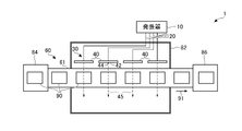
- FIG. 1A is a front view schematically showing an outline of a configuration example of a microwave irradiation device according to a first embodiment
- FIG. 1B is a plan view schematically showing an outline of a configuration example of the microwave irradiation device according to the first embodiment
- FIG. 2 is a schematic diagram showing an outline of a configuration example of a loop antenna.
- FIG. 3A is a schematic diagram for explaining the orientation of the antenna.
- FIG. 3B is a schematic diagram for explaining the orientation of the antenna.
- FIG. 4 is a plan view schematically showing an outline of a configuration example of the microwave irradiation device of the second embodiment.
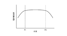
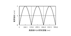
- FIG. 5 is a schematic diagram for explaining the magnitude of the electric field effective value according to the position along the directional irradiation axis in an example in which the antennas are provided facing each other.
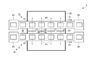
- FIG. 6 is a plan view schematically showing an outline of a configuration example of the microwave irradiation device of the third embodiment.
- FIG. 7 is a diagram schematically showing an outline of a configuration example of a microwave irradiation device according to a fourth embodiment.
- FIG. 8 is a schematic diagram for explaining the orientation of the antenna of the fourth embodiment.
- FIG. 9 is a schematic diagram for explaining the orientation of the antenna according to the comparative example.
- FIG. 10A is a front view schematically showing an outline of a configuration example of a microwave irradiation device according to a fifth embodiment
- 10B is a plan view schematically showing an outline of a configuration example of a microwave irradiation device according to a fifth embodiment
- FIG. 10C is a diagram schematically showing an outline of a configuration example of an end face seen from the side at the position of the antenna of the microwave irradiation device according to the fifth embodiment
- FIG. 11 is a schematic diagram for explaining the positional relationship between the intensity of the electric field generated by the antenna and the irradiated object according to the fifth embodiment
- FIG. 12 is a schematic diagram for explaining the positional relationship between the electric field intensity and the irradiated object according to the comparative example.
- FIG. 13 is a diagram schematically showing an outline of a configuration example of a microwave irradiation device according to the sixth embodiment.
- FIG. 14 is a schematic diagram for explaining the positional relationship between the intensity of the electric field generated by the antenna and the irradiated object according to the sixth embodiment.
- 15A is a front view schematically showing an outline of a configuration example of a microwave irradiation device according to a seventh embodiment;
- FIG. 15B is a plan view schematically showing an outline of a configuration example of a microwave irradiation device according to the seventh embodiment;
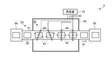
- FIG. FIG. 16 is a plan view schematically showing an outline of a configuration example of a microwave irradiation device according to an eighth embodiment.
- FIG. 17 is a schematic diagram showing an outline of a configuration example of a test apparatus used in Experimental Example 1.
- FIG. FIG. 18 is a diagram showing an example of test results in which the object to be heated according to Experimental Example 1 is vertically placed and heated.
- FIG. 19 is a diagram showing an example of test results in which the object to be heated was placed horizontally and heated according to Experimental Example 1.
- FIG. FIG. 20 is a diagram showing an outline of a configuration example of a test apparatus used in Experimental Examples 2, 3, and 6.
- FIG. FIG. 21 shows a photograph of the food model after heating with an output of 150 W using the test device in Experimental Example 2.
- FIG. 22 shows a photograph of a food model after heating with an output of 250 W using a commercial microwave oven as a comparative experiment.
- FIG. 23 is a diagram showing an outline of the implementation status of Experimental Example 3.
- FIG. 24 shows a photograph of the food model after heating in Experimental Example 3.
- FIG. 25A is a perspective view showing a thermal coupling analysis result according to Experimental Example 4.
- FIG. 25B is a cross-sectional view showing a result of thermal coupling analysis according to Experimental Example 4.
- FIG. 26A is a diagram showing a thermal coupling analysis result when the distance is 166.5 mm according to Experimental Example 5.
- FIG. 26B is a diagram showing a thermal coupling analysis result when the distance is 56.5 mm according to Experimental Example 5.
- FIG. FIG. 27 is a diagram showing the results of temperature measurement of the central portion (solid line) and the outer peripheral portion (broken line) of the object to be heated according to Experimental Example 6.
- FIG. 28 is a diagram showing an outline of a configuration example of a test apparatus used in Experimental Example 7.
- FIG. 29 shows images obtained by thermography of the first object to be heated, the second object to be heated, and the third object to be heated using the test apparatus according to Experimental Example 7.
- FIG. FIG. 30 shows, as a comparative experiment, an image obtained by thermography of a heating object heated using a commercial microwave oven.
- 31 is a schematic diagram of a model of a microwave irradiation device according to Experimental Example 8.
- FIG. FIG. 32 shows analysis results of electric field intensity formed between antennas in the model according to Experimental Example 8.
- FIG. FIG. 33 shows the analysis result of the electric field strength with respect to the irradiation distance from the oscillator in the waveguide, which was performed as a comparative analysis.
- FIG. 34 is a diagram showing a thermal coupled analysis result of the heat generation distribution of the object to be heated when the object to be heated is heated according to Experimental Example 8.
- FIG. 29 shows images obtained by thermography of the
- the microwave irradiation device of the present embodiment is configured to irradiate microwaves onto an object to be irradiated to internally heat the object.
- the object to be irradiated is, but not limited to, food, for example. Therefore, this microwave irradiation device and the microwave irradiation method using it can be used, for example, in the production of foods including packaged foods.
- the microwave irradiation apparatus has a conveying device, and a plurality of objects to be irradiated are conveyed one after another and heated one after another. A plurality of directional antennas that radiate microwaves are arranged along the transport direction.
- FIG. 1A is a front view schematically showing the outline of the configuration example of the microwave irradiation device 1 according to the present embodiment
- FIG. 1B schematically shows the outline of the configuration example of the microwave irradiation device 1 according to the present embodiment
- 2 is a schematic plan view;
- the microwave irradiation apparatus 1 includes a carrier device 60 that carries an object 90 to be heated and irradiated with microwaves.
- the conveying device 60 includes, for example, a belt 61 and rollers 62 .
- the belt 61 is wrapped around rollers 62 .
- the roller 62 is rotated by a motor (not shown) to move the belt 61 in the longitudinal direction.
- the object 90 to be irradiated is placed on the belt 61 and transported in the transport direction 91 by the movement of the belt 61 .
- a feeding device 84 is provided upstream of the conveying device 60 in the conveying direction 91 to sequentially feed the object 90 to be irradiated onto the belt 61 .
- An unloading device 86 for unloading the transported irradiation object 90 from the belt 61 is provided downstream of the transporting device 60 in the transporting direction 91 .
- the microwave irradiation device 1 includes an antenna group 30 having a plurality of antennas 40 configured to irradiate microwaves onto an irradiation object 90 conveyed by a conveying device 60 .
- a plurality of antennas 40 are arranged along the transport direction 91 .
- Each antenna 40 is, for example, a directional antenna such as a loop antenna, patch antenna, or the like. That is, each antenna 40 has an illumination surface 42 and is configured to emit microwaves from an illumination source 44 within the illumination surface 42 in the direction of a directional illumination axis 45 .
- the direction of the directional irradiation axis 45 of each antenna 40 is directed toward the irradiated object 90 transported by the transport device 60 .
- Each antenna 40 is fed from an oscillator 10 conducted through a feeding fixture 20, such as a coaxial cable.
- the periphery of the antenna group 30 is covered with metal to shield microwaves. That is, the carrier device 60 is provided so as to pass through or within the metal housing 82 , and the antenna group 30 is arranged within the metal housing 82 .
- FIG. 2 is a schematic diagram showing an outline of a configuration example of the loop antenna 51.
- the loop antenna 51 includes, for example, a conducting wire 52 having a length corresponding to one wavelength of the irradiated microwave and formed in an annular shape. Both ends of the conducting wire 52 are feeding points 53 .
- a coaxial cable 21 as the power supply device 20 is connected to the power supply point 53 .
- Coaxial cable 21 connects oscillator 10 and loop antenna 51 for conduction.
- the oscillator 10 supplies high frequency power to the loop antenna 51 via the coaxial cable 21 .
- a current is generated in the conducting wire 52 as an element, and the loop antenna 51 radiates radio waves to form an electric field.
- the opening surface 54 formed by the conducting wire 52 becomes the irradiation surface 42
- the center of the opening surface 54 becomes the irradiation source 44 .
- a directional illumination axis 45 is formed through the illumination source 44 in a direction perpendicular to the aperture plane 54 along which microwaves are emitted in both directions.
- the shape formed by the conducting wire 52 is not limited to a ring, and may be a ring of other shapes such as a square.
- FIG. 3A and 3B are schematic diagrams for explaining the orientation of the antenna 40.
- the antenna 40 is arranged such that the directional irradiation axis 45 is parallel to the surface of the belt 61 of the conveying device 60 on which the object 90 to be irradiated is placed, as shown in FIG. 3A, for example.
- the antenna 40 is positioned such that the directional irradiation axis 45 does not intersect any structure that reflects microwaves among the structures that make up the transport device 60 .
- the microwaves emitted from the directional antenna 40 spread somewhat, as shown as the diffuse emission axis 46 in FIGS. An electric field is formed which is the strongest. Since the directional irradiation axis 45 does not intersect with structures that reflect microwaves, strong reflected waves are not generated. As a result, no standing wave is generated, which can be caused by interference between the incident wave and the reflected wave. If a standing wave were generated by interference between a strong incident wave and a reflected wave, the electric field strength would be significantly different between the position of the antinode of the standing wave and the position of the node. . In the microwave irradiation device 1 of the present embodiment, since such a standing wave is not generated, the object 90 to be irradiated is prevented from being unevenly heated.
- the above-mentioned structure that reflects microwaves means a structure that reflects microwaves to the extent that standing waves that cause the above-described uneven heating are generated.
- the operation of the microwave irradiation device 1 of this embodiment will be described.
- the oscillator 10 outputs high frequency power corresponding to the frequency of microwaves.
- the frequency is, for example, but not limited to, 2.45 GHz, 915 MHz, or 450 MHz.
- the high-frequency power output from this oscillator 10 is supplied to the antenna 40 via the power supply device 20 .
- the antenna 40 irradiates microwaves in the direction of the directional irradiation axis 45 based on this feeding.
- the conveying device 60 rotates the belt 61 by rotating the roller 62 .
- the supply device 84 supplies the object 90 to be irradiated onto the belt 61 of the transport device 60 at regular intervals, for example.
- the conveying device 60 conveys the supplied irradiated object 90 in the conveying direction 91 to pass in front of the plurality of antennas 40 inside the metal housing 82 .
- An irradiated object 90 passing in front of the antenna 40 is irradiated with microwaves from the antenna 40 .
- the irradiated object 90 is dielectrically heated by the microwaves.
- the heated irradiation object 90 is transported to the outside of the metal housing 82 by the transport device 60 .
- the unloading device 86 unloads the heated object 90 to be irradiated from the conveying device 60 .
- the directional antennas 40 are used in the antenna group 30, and are designed so that the directional irradiation axis 45 does not intersect the microwave-reflecting structure of the transport device 60. Therefore, no standing wave derived from the reflected wave is generated in the irradiated microwave. As a result, the object 90 to be irradiated is uniformly heated.
- a multimode heating device that heats an object by reflecting microwaves in a metal housing
- a single-mode heating device in which the object to be heated is placed in a waveguide that carries microwaves. Reflection of microwaves is deliberately used in such devices. That is, a standing wave is intentionally created by reflection, and this standing wave causes dielectric heating. However, in such a standing wave, a difference in electric field strength occurs depending on the location, which is conspicuous between the antinode position and the node position. This uneven electric field intensity causes uneven heating of the object to be heated.
- the microwave irradiation device 1 of the present embodiment is adjusted so as not to generate standing waves, so uniform heating can be achieved.
- a heating device using a waveguide tends to be large, especially when the frequency is low, such as the waveguide becoming large. Further, when a plurality of types of heating devices are combined for uniform heating, the size of the entire device tends to increase.
- the microwave irradiation device 1 of the present embodiment does not use a waveguide and does not need to be combined with a plurality of types of devices, so that the size of the device can be easily reduced. Also, since no waveguide is used, it is easy to use relatively low-frequency microwaves. By lowering the frequency, it is also possible to deepen the power half-life depth.
- the irradiated object 90 is held on the belt 61 of the conveying device 60 during microwave irradiation has been described as an example, but the present invention is not limited to this.
- Object 90 may be configured to be held by a stationary holding table.
- the antenna 40 is preferably provided so that the directional irradiation axis 45 does not intersect the structure constituting the holding base. In this case as well, the generation of standing waves due to reflected waves is suppressed, and uneven heating due to dielectric heating is suppressed.
- the microwave irradiation device 1 can be incorporated into processing devices for various uses, or configured in an appropriate manner. For example, when used for heat sterilization of food that is sealed and packaged, the microwave irradiation device 1 does not pressurize the object to be irradiated 90, which is the food that is sealed and packaged, or the time required for sterilization. It will be incorporated into a device configured to insulate. Alternatively, in order to be used for reaction processing of materials, the object to be irradiated 90, which is the object to be treated, may be housed in a suitable reaction container, and the conveying device 60 may be configured as a pipe or the like through which the object to be treated flows. You may
- FIG. 4 is a plan view schematically showing an outline of a configuration example of the microwave irradiation device 2 of the second embodiment.
- illustration of the oscillator 10, the power supply device 20, etc. is omitted.
- the antenna 40 is arranged on one side of the carrier device 60, whereas in the microwave irradiation device 2 of the second embodiment shown in FIG. Antennas 40 are arranged on both sides of the carrier device 60 . Therefore, in the microwave irradiation device 1 of the first embodiment shown in FIG.
- microwaves are irradiated to the irradiated object 90 from one side, whereas the microwave irradiation device of the second embodiment shown in FIG. In 2, the object 90 to be irradiated is irradiated with microwaves from both sides.
- the antennas 40 are provided facing each other with the carrier device 60 interposed therebetween, and the directional irradiation axes 45 of the facing antennas 40 overlap.
- FIG. 5 is a schematic diagram showing the magnitude of the electric field effective value according to the position along the directional irradiation axis 45 of the antennas 40 provided facing each other.
- Each of the antennas 40 facing the first position P1 and the second position P2 is arranged. Therefore, the conveying device 60 passes between the first position P1 and the second position P2, and the irradiated object 90 passes.
- the microwave irradiation device 2 of this embodiment is configured such that the effective value of the electric field is substantially constant between the first position P1 and the second position P2.
- microwaves are irradiated from both sides in the direction transverse to the conveying direction 91, even if the object 90 to be irradiated in the direction transverse to the conveying direction 91 is somewhat large, it is heated from both sides. so that uniform heating can be achieved. Note that such an effect can be obtained if microwaves are applied to the irradiated object 90 from both sides, so the antennas 40 do not necessarily have to face each other.
- the antennas 40 face each other, and the microwave irradiation device 2 is configured such that the electric field strength of the microwaves is substantially constant in the direction transverse to the transport direction 91. .
- the object to be irradiated 90 can be heated more uniformly.
- a constant electric field intensity between the antennas 40 facing each other means that the electric field intensity is constant to the extent that the requirement for uniform heating of the irradiated object 90 is satisfied.
- the object 90 to be irradiated can be heated more uniformly.
- the central part of the object 90 may be particularly heated. It has been found that uneven irradiation of microwaves to one side of the object to be irradiated 90 may result in heating of the outer peripheral portion of the object to be irradiated 90 in particular. Therefore, uniform irradiation from both sides and uneven irradiation from one side are combined to heat the central portion and the outer peripheral portion of the object to be irradiated 90, thereby uniformly heating the entire object to be irradiated 90. Alternatively, it may be intentionally non-uniformly heated.
- uniform microwave irradiation may be performed as the first irradiation
- uneven microwave irradiation may be performed as the second and third irradiations. That is, the following irradiation can be performed in a state where the object to be irradiated 90 is positioned equidistant from the two antennas 40 between the pair of antennas 40 .
- the object 90 In the first irradiation, the object 90 can be irradiated with microwaves having the same irradiation intensity from the two antennas 40 .
- the object 90 to be irradiated can be irradiated with microwaves from one of the antennas 40 .
- the object 90 to be irradiated can be irradiated with microwaves from the other antenna 40 .
- the irradiated object 90 can be uniformly heated by a combination of the first irradiation, the second irradiation and the third irradiation. Alternatively, only the first irradiation and the second irradiation may be performed.
- the first irradiation, the second irradiation, and the third irradiation may be performed by the same pair of antennas 40 as described above, or may be performed by multiple pairs of antennas 40.
- microwaves with the same irradiation intensity are emitted from two opposing antennas 40 in part, , microwaves may be emitted from the antenna 40 on one side, and microwaves may be emitted from the antenna 40 on the opposite side in some cases.
- the object 90 to be irradiated is transported between the antennas 40 by the transport device 60, so that the first irradiation, the second irradiation and the third irradiation can be performed.
- the pair of antennas 40 are provided facing each other, while in the portion where the second irradiation and the third irradiation are performed, the first embodiment
- the antenna 40 may be provided only on one side like the microwave irradiation device 1 of .
- one of the pair of opposing antennas 40 and the other may have different irradiation intensities.
- the irradiated object 90 may be brought closer to one or the other.
- the transport device 60 may be configured to move the object to be irradiated 90 also in a direction orthogonal to the transport direction.
- the antennas 40 may be arranged such that the distances between the carrier device 60 and the antennas 40 are different.
- the modification of the heating method described here may be performed using an irradiation device different from the microwave irradiation device 2 of the second embodiment.
- the antennas may not be arranged along the carrier.
- the illumination device may have only two opposing antennas and no carrier device.
- the transport device may also be configured to move the object between two opposing antennas.
- FIG. 6 is a plan view schematically showing an outline of a configuration example of the microwave irradiation device 3 of the third embodiment.
- a loop antenna 51 is used as the antenna 40 constituting the antenna group 30 .
- both front and back sides of the opening surface 54 are the irradiation surfaces 42 , and microwaves are irradiated in both directions along the directional irradiation axis 45 .
- a first conveying device 71 and a second conveying device 72 corresponding to the conveying device 60 of the first embodiment are provided on both sides of the loop antennas 51 arranged in plurality. are provided to form a transport device group 70 .
- the microwaves radiated to both sides from one loop antenna 51 are applied to the irradiated object 90 conveyed by the first conveying device 71 and the irradiated object conveyed by the second conveying device 72, respectively. Since the object 90 is irradiated, the energy efficiency of the microwave irradiation device 3 is good even with a simple configuration.
- antennas may be provided on both sides of the conveying device, as in the second embodiment.
- Loop antennas 51 may be provided on both sides of the conveying device, and a large number of conveying devices may be arranged in parallel.
- the microwave irradiation device of the present embodiment is configured to irradiate microwaves onto an object to be irradiated to internally heat the object.
- the object to be irradiated is, but not limited to, food, for example.
- FIG. 7 is a diagram schematically showing an outline of a configuration example of the microwave irradiation device 4 according to this embodiment.
- the microwave irradiation device 4 includes a holder 66 that holds an irradiation object 90, which is an object to be heated and is irradiated with microwaves.
- the holder 66 can be, for example, a table on which the object 90 to be irradiated is held.
- the microwave irradiation device 4 includes an antenna 40 configured to irradiate microwaves onto an irradiation object 90 held by a holder 66 .
- the antenna 40 is, for example, a directional antenna such as a loop antenna, a patch antenna, or the like.
- the antenna 40 has an irradiation surface 42 and is configured to irradiate microwaves from an irradiation source 44 within the irradiation surface 42 in the direction of a directional irradiation axis 45 .
- the direction of the directional emission axis 45 of the antenna 40 is along the holding surface of the holder 66 .
- the antenna 40 is fed from the oscillator 10 conducted through a feeder 20, such as a coaxial cable.
- the circumference of the antenna 40 is covered with metal for microwave shielding. That is, the holder 66 and the antenna 40 are arranged inside the metal housing 82 .
- FIG. 8 is a schematic diagram for explaining the orientation of the antenna 40.
- the antenna 40 is arranged such that the directional irradiation axis 45 is parallel to the surface of the holder 66 on which the irradiated object 90 is placed, as shown in FIG. 8, for example.
- the antenna 40 is arranged so that at least the directional irradiation axis 45 does not intersect any structure that reflects microwaves among the structures that constitute the holder 66 .
- the microwave emitted from the directional antenna 40 spreads to some extent as shown as a diffuse emission axis 46 in FIG. an electric field is formed. Since the directional irradiation axis 45 does not intersect with structures that reflect microwaves, strong reflected waves are not generated. As a result, no standing wave is generated, which can be caused by interference between the incident wave and the reflected wave.
- FIG. 9 is a schematic diagram showing a comparative example.
- the microwaves will reflect off the surface of the retainer 66 .
- the incident wave and the reflected wave interfere to generate a standing wave.
- the electric field strength differs greatly between the position of the antinode and the position of the node of the standing wave, which may cause uneven heating in the object 90 to be irradiated.
- the above-mentioned structure that reflects microwaves means a structure that reflects microwaves to such an extent that standing waves that cause the above-described uneven heating are generated.
- the oscillator 10 outputs high frequency power corresponding to the frequency of microwaves.
- the frequency is, for example, but not limited to, 2.45 GHz, 915 MHz, or 450 MHz.
- the high-frequency power output from this oscillator 10 is supplied to the antenna 40 via the power supply device 20 .
- the antenna 40 irradiates microwaves in the direction of the directional irradiation axis 45 based on this feeding.
- An irradiated object 90 placed on the holder 66 in front of the antenna 40 is irradiated with microwaves from the antenna 40 .
- the irradiated object 90 is dielectrically heated by the microwaves.
- the directional antenna 40 is used as an antenna for irradiating microwaves, and is designed so that the directional irradiation axis 45 does not intersect with the microwave-reflecting structure of the holder 66. there is Therefore, no standing wave derived from the reflected wave is generated in the irradiated microwave. As a result, the object 90 to be irradiated is uniformly heated.
- a multimode heating device that heats an object by reflecting microwaves in a metal housing
- a single-mode heating device in which the object to be heated is placed in a waveguide that carries microwaves. Reflection of microwaves is deliberately used in such devices. That is, a standing wave is intentionally created by reflection, and this standing wave causes dielectric heating. However, in such a standing wave, a difference in electric field strength occurs depending on the location, which is conspicuous between the antinode position and the node position. This uneven electric field intensity causes uneven heating of the object to be heated.
- the microwave irradiation device 4 of the present embodiment is adjusted so as not to generate standing waves, so uniform heating can be achieved.
- a heating device using a waveguide tends to be large, especially when the frequency is low, such as the waveguide becoming large. Further, when a plurality of types of heating devices are combined for uniform heating, the size of the entire device tends to increase.
- the microwave irradiation device 4 of the present embodiment does not use a waveguide and does not need to be combined with a plurality of types of devices, so that the size of the device can be easily reduced. Also, since no waveguide is used, it is easy to use relatively low-frequency microwaves. By lowering the frequency, it is also possible to deepen the power half-life depth.
- the holder 66 may move back and forth along the directional irradiation axis 45 of the antenna 40 or rotate in a plane parallel to the directional irradiation axis 45. . By moving the irradiation object 90 in such a direction, the irradiation object 90 can be heated more uniformly. Also, the same may be done by moving the antenna 40 instead of the holder 66 .
- the microwave irradiation apparatus of this embodiment is configured to irradiate microwaves to an object to be irradiated, such as food, to heat the inside of the object to be irradiated.
- the microwave irradiation apparatus has a conveying device, and a plurality of objects to be irradiated are conveyed one after another and heated one after another.
- FIG. 10A is a front view schematically showing an outline of a configuration example of the microwave irradiation device 5 according to the second embodiment.
- FIG. 10B is a plan view schematically showing an outline of a configuration example of the microwave irradiation device 5 according to the second embodiment.
- FIG. 10C is a diagram schematically showing an outline of a configuration example of an end face seen from the side at the position of the antenna 40 of the microwave irradiation device 5 according to the second embodiment.
- the microwave irradiation device 5 includes a carrier device 60 as a holder that carries an object 90 to be heated and irradiated with microwaves.
- the conveying device 60 includes, for example, a belt 61 and rollers 62 .
- the belt 61 is wrapped around rollers 62 .
- the roller 62 is rotated by a motor (not shown) to move the belt 61 in the longitudinal direction.
- the object 90 to be irradiated is placed on the belt 61 and transported in the transport direction 91 by the movement of the belt 61 .
- a feeding device 84 is provided upstream of the conveying device 60 in the conveying direction 91 to sequentially feed the object 90 to be irradiated onto the belt 61 .
- An unloading device 86 for unloading the transported irradiation object 90 from the belt 61 is provided downstream of the transporting device 60 in the transporting direction 91 .
- the microwave irradiation device 5 includes an antenna 40 configured to irradiate microwaves onto an object 90 to be irradiated which is transported by the transport device 60 .
- the antenna 40 is, for example, a loop antenna that is a type of directional antenna.
- the loop antenna is as described with reference to FIG.
- the antenna 40 is fed from the oscillator 10 conducted through a feeder 20, such as a coaxial cable.
- the belt 61 of the conveying device 60 is provided so as to pass through the irradiation surface 42 that is the opening surface 54 of the antenna 40 that is the loop antenna 51 . That is, the irradiated object 90 is conveyed in the conveying direction 91 so as to pass through the antenna 40 .
- the irradiation surface 42 of the antenna 40 is perpendicular to the transport direction 91 and the directional irradiation axis 45 of the antenna 40 is parallel to the transport direction 91 .
- the circumference of the antenna 40 is covered with metal to shield microwaves. That is, the carrier device 60 is provided so as to pass through the metal housing 82 , and the antenna 40 is arranged inside the metal housing 82 .
- the directional irradiation axis 45 of the antenna 40 does not intersect any structure that reflects microwaves among the structures constituting the transport device 60 .
- no standing wave is generated, which can be caused by interference between the incident wave and the reflected wave.
- the object 90 to be irradiated is prevented from being unevenly heated.
- the irradiation object 90 passes through the irradiation source 44 of the antenna 40, so that the irradiation object 90 can be efficiently and uniformly heated.
- FIG. 11 schematically shows the electric field strength as a function of location with the amplitude of the dashed line 92 .
- the central portion of the object 90 to be irradiated passes through the irradiation source 44 of the antenna 40 having a strong electric field intensity. Therefore, the object to be irradiated 90 generates heat at its central portion, and is efficiently heated from the inside of the object to be irradiated 90 .
- the irradiation object 90 placed on the belt 61 of the conveying device 60 moves in the conveying direction 91, the heat generation position within the irradiation object 90 changes, and the irradiation object 90 is evenly heated.
- FIG. 12 schematically shows a heating device with an antenna 40 arranged laterally with respect to the conveying direction 91 of a generally known conveying device 60 .
- the electric field intensity is schematically shown by the dashed line 92, in the arrangement shown in FIG. .
- the central portion may be difficult to heat.
- the microwave irradiation device 5 of the present embodiment the electric field intensity becomes stronger at the central portion of the object 90 to be irradiated.
- the oscillator 10 outputs high frequency power corresponding to the frequency of microwaves.
- the frequency is, for example, but not limited to, 2.45 GHz, 915 MHz or 450 MHz.
- the high-frequency power output from this oscillator 10 is supplied to the antenna 40 via the power supply device 20 .
- the antenna 40 irradiates microwaves in the direction of the directional irradiation axis 45 based on this feeding.
- the conveying device 60 rotates the belt 61 by rotating the roller 62 .
- the supply device 84 supplies the object 90 to be irradiated onto the belt 61 of the transport device 60 at regular intervals, for example.
- the conveying device 60 conveys the supplied irradiated object 90 in the conveying direction 91 to pass through the opening surface 54 of the antenna 40 which is the loop antenna 51 in the metal housing 82 .
- Microwaves are emitted from the antenna 40 to the object 90 passing through the opening surface 54 of the antenna 40 .
- the irradiated object 90 is dielectrically heated by the microwaves.
- the heated irradiation object 90 is transported to the outside of the metal housing 82 by the transport device 60 .
- the unloading device 86 unloads the heated object 90 to be irradiated from the conveying device 60 .
- the directional antenna 40 is used, and is designed so that the directional irradiation axis 45 does not intersect the microwave-reflecting structure of the carrier device 60 . Therefore, no standing wave derived from the reflected wave is generated in the irradiated microwave. As a result, the object 90 to be irradiated is uniformly heated. Also, the irradiated object 90 passes through the irradiation source 44 of the antenna 40 . Therefore, a strong electric field is generated inside the object to be irradiated 90, and the object to be irradiated 90 is efficiently heated from the inside. In addition, the same effects as those of the fourth embodiment can be obtained.
- the microwave irradiation device 5 can be incorporated into processing devices for various uses, or configured in an appropriate manner.
- the microwave irradiator 4 does not pressurize the object to be irradiated 90, which is the food that is sealed and packaged, or the time required for sterilization. It will be incorporated into a device configured to insulate.
- the object to be irradiated 90 which is the object to be treated, may be housed in a suitable reaction container, and the conveying device 60 may be configured as a pipe or the like through which the object to be treated flows. You may
- FIG. 13 is a diagram schematically showing an outline of a configuration example of the microwave irradiation device 6 according to the sixth embodiment.
- the microwave irradiation device 6 has an antenna group 30 including two antennas 40 .
- the antenna 40 is, for example, a directional antenna such as a loop antenna, a patch antenna, or the like. Although not limited to this, the antenna 40 is assumed to be the loop antenna 51 here.
- the two antennas 40 of the antenna group 30 are arranged in parallel so that their irradiation surfaces 42 face each other.
- a holder 66 for holding an object 90 to be irradiated is provided so as to pass through the opening surface 54 forming the irradiation surface 42 .
- the irradiation object 90 held by the holder 66 is sandwiched between the two antennas 40 .
- the directional irradiation axes 45 of the two antennas 40 are parallel to the surface of the holder 66 on which the irradiated object 90 is held so as not to generate strong reflected waves.
- the two antennas 40 irradiate the object 90 with microwaves from opposite sides. The microwaves emitted from each antenna 40 overlap each other.
- FIG. 14 schematically shows the electric field intensity depending on the location with the amplitude of the dashed line 92 .
- an object 90 to be irradiated is irradiated with microwaves from both sides.
- Fig. 5 above is a schematic diagram showing the magnitude of the electric field effective value according to the position along the directional irradiation axis 45 of the antennas 40 provided facing each other.
- Each of the antennas 40 facing the first position P1 and the second position P2 is arranged. Therefore, the irradiated object 90 is arranged between the first position P1 and the second position P2.
- the microwave irradiation device 4 of this embodiment is configured such that the effective value of the electric field is substantially constant between the first position P1 and the second position P2.
- microwaves are irradiated from both sides of the object 90 to be irradiated, and the electric field strengths formed by them are almost the same even if the positions are different, so that the object 90 to be irradiated can be uniformly heated.
- a constant electric field intensity between the antennas 40 facing each other means that the electric field intensity is constant to the extent that the requirement for uniform heating of the irradiated object 90 is satisfied.
- the object 90 to be irradiated can be heated more uniformly.
- the same effects as those of the microwave irradiation device 4 of the fourth embodiment can be obtained.
- the directional irradiation axes 45 of the two antennas 40 are parallel to the surface of the holder 66 on which the irradiated object 90 is placed so as not to generate strong reflected waves.
- the directional irradiation axis 45 is preferably parallel to the mounting surface of the holder 66, but is not limited to this.
- the two antennas 40 are at least a structure reflecting microwaves constituting a holder 66 in which the directional emission axis 45 exists between the mutually facing aperture surfaces 54 of the two antennas 40 . It is preferable that they are arranged so as not to cross each other. By doing so, the irradiated microwave does not generate a standing wave derived from the reflected wave, and as a result, the irradiated object 90 is uniformly heated.
- FIG. 15A is a front view schematically showing an outline of a configuration example of the microwave irradiation device 7 according to the seventh embodiment
- FIG. 15B is a configuration example of the microwave irradiation device 7 according to the seventh embodiment
- FIG. 2 is a plan view schematically showing the outline of.
- the microwave irradiation device 7 according to the seventh embodiment is an object to be heated and irradiated with microwaves, similarly to the microwave irradiation device 5 according to the fifth embodiment.
- a conveying device 60 for conveying the irradiation object 90 is provided.
- the microwave irradiation device 7 of the seventh embodiment includes an antenna group 30 having a plurality of antennas 40 configured to irradiate microwaves onto an irradiation object 90 transported by a transport device 60 .
- a plurality of antennas 40 are arranged along the transport direction 91 .
- Each antenna 40 is, for example, a loop antenna 51 .
- a belt 61 of the conveying device 60 is arranged to pass through each antenna 40 .
- Each antenna 40 is fed from an oscillator 10 conducted through a feeding fixture 20, such as a coaxial cable.
- the plurality of antennas 40 are arranged such that the effective value of the electric field is substantially constant between adjacent antennas 40, like the antennas 40 of the microwave irradiation device 6 of the sixth embodiment.
- the antenna group 30 is surrounded by a metal housing 82 for shielding microwaves.
- the plurality of antennas 40 make the electric field intensity of the microwaves substantially constant along the belt 61 .
- the object to be irradiated 90 conveyed by the conveying device 60 moves in this electric field having a constant intensity.
- the irradiated object 90 is configured to pass through the irradiation source 44 of each antenna 40 .
- the microwave irradiation device 7 can efficiently and evenly heat the object 90 to be irradiated.
- effects similar to those of the microwave irradiation apparatuses of the first to sixth embodiments can be obtained.
- FIG. 16 is a plan view schematically showing an outline of a configuration example of the microwave irradiation device 8 according to the eighth embodiment.
- the microwave irradiation device 8 according to the eighth embodiment is similar to the microwave irradiation device 7 according to the seventh embodiment, except that the orientation of some of the antennas 40 is changed. , and differs from the microwave irradiation device 7 according to the seventh embodiment in that the directional irradiation axis 45 of the antenna 40 is not along the conveying direction 91 .
- heating the object 90 to be irradiated it is not always preferable to uniformly supply electric power.
- the entire object 90 is uniformly heated by supplying more power to the areas that are not easily heated. become.
- the example shown in FIG. 16 is an example in which the lower side and the upper side of the drawing of the object to be irradiated 90 are regions that are difficult to heat.
- the two antennas 40 on the supply device 84 side are arranged such that the directional irradiation axes 45 of the two antennas 40 facing each other are biased to the lower side of the drawing and the other to the upper side of the drawing with respect to the conveying direction 91.
- electric fields directed to the lower side of the drawing and the upper side of the drawing are formed, respectively, and electric power is applied from different directions to the irradiated object 90 passing therethrough.
- the entire irradiated object 90 is uniformly heated.
- the same effects as those of the microwave irradiation device 7 of the seventh embodiment can be obtained.
- FIG. 17 shows an outline of a configuration example of this test apparatus 100 .
- the test apparatus 100 has an oscillator 110 , two loop antennas 140 and a food holder 166 located within a metal housing 182 .
- the oscillation frequency of oscillator 110 was set to 450 MHz.
- the two loop antennas 140 were arranged such that their open surfaces face each other and their directional irradiation axes 145 are parallel to the food holder 166 .
- Feeding to the loop antenna 140 was in-phase feeding.
- a polyethylene (PE) plate with a thickness of 5 mm was used for the food holding table 166 .
- a food holding table 166 was arranged so as to pass through the two loop antennas 140 .
- PE polyethylene
- the object to be heated 190 was a polypropylene (PP) material tray with a length of 115 mm, a width of 80 mm, and a depth of 20 mm, and 150 g of potato salad was served.
- a heating object 190 was placed centrally between the two loop antennas 140 on the food holding platform 166 .
- the object to be heated 190 may be placed vertically with the length direction of the tray perpendicular to the directional irradiation axis 145 or with the length direction of the tray parallel to the directional irradiation axis 145 . There are two types of arrangement (horizontal placement). Temperature measurement was performed by attaching a plurality of thermolabels (manufactured by NOF Giken Kogyo Co., Ltd.) to the surface of the potato salad. Temperature measurements were taken after heating for 5 minutes at an output of 150 W.
- FIG. 18 shows the test results of heating the object 190 to be heated vertically.
- thermolabels (d) and (e) placed away from the directional irradiation axis 145 that is, near the center of the short side of the tray, both exhibited temperatures of less than 50°C.
- FIG. 19 shows the test result of heating the object 190 to be heated horizontally.
- Example 2 The heating characteristics of the microwave irradiation apparatus according to the above-described embodiment were further evaluated using a heat indicator gel as a food model as the object to be heated.
- FIG. 20 shows an outline of a configuration example of a test device 200 used for evaluation.
- This test apparatus 200 has the configuration of the portion including the pair of opposing antennas 40 in the microwave irradiation apparatus 2 of the second embodiment described with reference to FIG. This corresponds to the configuration of the microwave irradiation device 6 of the embodiment. This situation also corresponds to the state in which the object 90 is positioned between the two antennas 40 by the conveying device 60 in the seventh embodiment described with reference to FIGS. 15A and 15B.
- the configuration of the test apparatus 200 was as follows.
- the test apparatus 200 includes a metal housing 282 that shields electromagnetic waves.
- the metal housing 282 is made of aluminum and has dimensions of 500 mm width, 350 mm length, and 400 mm height.
- a holding table 266 is provided horizontally in the metal housing 282 .
- the holding base 266 is made of glass epoxy material and has dimensions of 331 mm in width and 5 mm in thickness.
- a first loop antenna 240a is provided at one end in the width direction of the holding table 266 via a first bracket 249a, and a second loop antenna 240a is provided at the other end in the width direction of the holding table 266 via a second bracket 249b.
- Antenna 240b is provided.
- the first bracket 249a and the second bracket 249b are each made of polyethylene (PE) material.
- the first loop antenna 240a and the second loop antenna 240b were each made of aluminum material and formed into a rectangular shape, and had outer dimensions of 214 mm in length, 111 mm in height, and 2 mm in thickness.
- the first loop antenna 240 a and the second loop antenna 240 b were arranged so as to face each other, and were installed so that the directional irradiation axis of the radiated microwaves was parallel to the holding table 266 .
- the distance between the first loop antenna 240a and the second loop antenna 240b was 333 mm.
- the material of the metal housing 282 is not limited to aluminum, and may be other metal materials such as iron and stainless steel.
- the material of the holding base 266, the first bracket 249a and the second bracket 249b may be other low dielectric constant and low loss materials such as resin materials such as polypropylene, polyethylene terephthalate, and polycarbonate. .
- a microwave oscillator (not shown) was connected to the first power supply port 223a and the second power supply port 223b provided on the metal housing 282 via a coaxial cable (not shown).
- This coaxial cable is branched in the middle, and the power output from the oscillator is fed in parallel to the first feeding port 223a and the second feeding port 223b.
- the first feeding port 223a is connected to the first feeding point 253a of the first loop antenna 240a.
- the second feeding port 223b is connected to the second feeding point 253b of the second loop antenna 240b.
- the frequency of the output power of the microwave oscillator was set to 450 MHz.
- the microwave power output from the microwave oscillator is fed in phase to the first loop antenna 240a and the second loop antenna 240b.
- Microwaves are radiated from the first loop antenna 240a and the second loop antenna 240b.
- a heat indicator gel was used as the food model 290.
- This heat indicator gel contains xylose and glycine, and is configured to turn brown when the temperature rises to about 70° C. or higher due to the Maillard reaction by them.
- the electrical properties, such as permittivity and conductivity, of the thermal indicator gel were adjusted to be generally equal to those of commercial potato salad by adjusting the concentrations of added oil, salt, and the like.
- Food model 290 was made by filling a cup of polypropylene (PP) material with 150 g of thermal indicator gel. In addition, the seal was not carried out after filling.
- PP polypropylene
- This food model 290 is placed at an intermediate position between the first loop antenna 240a and the second loop antenna 240b on the holding table 266. That is, the distance from the first loop antenna 240a and the second loop antenna 240b to the center of the food model 290 was 166.5 mm. A food model 290 was heated with an output of 150 W.
- the food model 290 was heated with a commercial microwave oven (manufactured by Panasonic Corporation, output 250 W).
- FIG. 21 shows a photograph of the food model 290 after heating with the test device 200 at 150 W power.
- the upper row shows the case of heating time of 4 minutes, and the lower row shows the case of heating time of 6 minutes.
- the left column shows the state of the surface of the food model 290 photographed from above.
- the horizontal direction is the direction of the directional radiation axis of the first loop antenna 240a and the second loop antenna 240b.
- the right column shows a vertical cross section of the food model 290 cut along the dashed-dotted line in the left column.
- the central portion of the food model 290 was uniformly discolored to brown, indicating that the central portion was evenly heated.
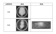
- Fig. 22 shows a photograph of a food model 290 after heating with an output of 250 W using a commercial microwave oven as a comparative experiment.
- the upper row shows the case of heating time of 3 minutes, and the lower row shows the case of heating time of 5 minutes.
- the left column shows the state of the surface of the food model 290 photographed from above.
- the right column shows a vertical cross section of the food model 290 cut along the dashed-dotted line in the left column.
- the outer circumference of the food model 290 turned dark brown, indicating that the outer circumference was overheated. It is considered that the microwave continued to irradiate the outer periphery of the food model 290 while being multiple-reflected inside the refrigerator. Furthermore, the heat generated in the outer peripheral portion of the food model 290 was not uniform along the circumference of the container, and there was a heat loss that did not generate heat in the portion surrounded by a circle 299 in the figure. This indicates that there is no uniformity in the standing wave distribution formed by the reflection of microwaves on the metal housing. This suggested that there was no reproducibility of heating.
- the testing apparatus 200 according to the present embodiment when used, it was confirmed that the central portion of the food could be selectively heated by an irradiation method that suppresses standing waves.
- Example 3 In Experimental Example 2 described above, the heating conditions at positions equidistant from the first loop antenna 240a and the second loop antenna 240b were examined. In this experimental example, the heating state at a position biased toward either one of the first loop antenna 240a and the second loop antenna 240b was examined. This situation corresponds to the state of the first embodiment described with reference to FIG. 1B or the like, the state of the third embodiment described with reference to FIG. 6, or the state of the seventh embodiment described with reference to FIG. 3 corresponds to a state in which the object 90 to be irradiated is transported to a position biased with respect to the two antennas 40 by the transport device 60 .
- FIG. 23 is a diagram showing an outline of the implementation status of this experimental example.
- the test apparatus 200 shown in FIG. 20 was used.
- the food model 290 was placed at a position where the distance from the first loop antenna 240a to the center of the food model 290 was 56.5 mm.
- the output of the test device 200 was set to 150 W, and heating was performed for 5 minutes.
- FIG. 24 shows a photograph of the food model 290 after heating.
- the photograph on the left shows the appearance of the surface of the food model 290 taken from above.
- the horizontal direction is the direction of the directional irradiation axis of the first loop antenna 240a and the second loop antenna 240b
- the left side is the first loop antenna 240a side closer to the food model 290
- the right side is the food model 290. It is the second loop antenna 240b side away from the model 290.
- FIG. 24 the photograph on the right shows a vertical cross section of the food model 290 cut at the position of the dashed line shown in the photograph on the left.
- the left side is the first loop antenna 240a side closer to the food model 290
- the right side is the second loop antenna 240b side farther from the food model 290.
- the outer peripheral portion of the food model 290 was heated in this case. It was also found that the heat generation range near the antenna is wider than the heat generation range far from the antenna, and the degree of heat generation is also large.
- the object to be heated is placed near one side of the pair of opposing antennas and arranged asymmetrically with respect to the pair of antennas, It was found that the wraparound of the electric field to the outer peripheral portion of the object to be heated increased, and the outer peripheral portion could be efficiently heated without causing heat loss.
- CST STUDIO SUITE manufactured by Dassault Systèmes
- PP polypropylene
- this object to be heated 390 was arranged at an intermediate position between the first loop antenna 340a and the second loop antenna 340b facing each other. That is, the distance from the center of the heating object 390 to each antenna was set to 166.5 mm.
- the holding base 366 on which the object to be heated 390 is arranged is arranged so as to pass through the first loop antenna 340a and the second loop antenna 340b.
- this model is closer to the microwave irradiation device 6 according to the sixth embodiment shown in FIG. 13 than the test device 200 shown in FIG.
- the physical property values of the holding table 366 are set to imitate a low dielectric constant, low loss resin, this model substantially corresponds to the device configuration of the test device 200 shown in FIG. It can be considered that the configuration of the microwave irradiation device 6 according to the sixth embodiment shown is also reproduced.
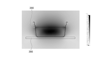
- FIG. 25A and 25B show thermal coupling analysis results.
- FIG. 25A shows the analysis results in a perspective view
- FIG. 25B shows a cross section passing through the center of the object to be heated 390 and perpendicular to the directional irradiation axes of the first loop antenna 340a and the second loop antenna 340b.
- the central portion of the object 390 to be heated strongly generated heat and reached a high temperature.
- the results of this numerical analysis are in good agreement with the experimental results. This numerical analysis was confirmed to be reliable.
- Example 5 The microwave irradiation device 1 of the first embodiment described with reference to FIG. 1B and the like, the microwave irradiation device 4 of the fourth embodiment described with reference to FIG. 7, and the description with reference to FIG. 10A and the like Analysis by numerical simulation was performed in the device configuration corresponding to the microwave irradiation device 5 of the fifth embodiment.
- the distance from the loop antenna 440 to the center of the object to be heated 490 was 166.5 mm.
- the distance from the loop antenna 440 to the center of the heated object 490 was 56.5 mm.
- the temperature distribution was analyzed when the output was set to 150 W and heating was performed for 5 minutes.
- ⁇ result> 26A and 26B show thermal coupling analysis results. As shown in FIG. 26A, when the distance from the loop antenna 440 to the center of the object 490 to be heated is 166.5 mm, it was found that the side of the object 490 to be heated that is particularly close to the loop antenna 440 generates heat. . By arranging the antenna on only one side of the heating target and irradiating the heating target with microwaves asymmetrically, it is possible to selectively heat the outer periphery of the heating target on the antenna side. Became.
- FIG. 26B shows the results when the distance between the object to be heated 490 and the loop antenna 440 is shortened compared to the case of FIG. 26A and the distance from the loop antenna 440 to the center of the object to be heated 490 is 56.5 mm.
- ⁇ Method> Using the test apparatus 200 shown in FIG. 20, an experiment was conducted by filling a cup made of polypropylene (PP) with 140 g of commercially available potato salad and using a sample that was not sealed after filling as an object to be heated.
- the heating conditions were as follows. First, an object to be heated was arranged at an intermediate position between the first loop antenna 240a and the second loop antenna 240b, and heated at an output of 150 W for 2.5 minutes. After heating, it was left for 1.5 minutes as an interval. Subsequently, the object to be heated was placed at a position where the distance from the first loop antenna 240a to the center of the object to be heated was 56.5 mm, and heated at an output of 150 W for 2.5 minutes. The temperature of the object to be heated during this period was measured using an optical fiber thermometer.
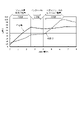
- FIG. 27 shows the results of temperature measurement of the central portion (solid line) and the peripheral portion (broken line) of the object to be heated.
- the central part of the object to be heated is heated more than the peripheral part, and the temperature after heating for 2.5 minutes is 70°C at the edge and 45°C at the periphery.
- the temperature at the end of the interval period was 67°C in the center and 45°C in the outer part.
- An object to be heated is arranged at an intermediate position between the first loop antenna 240a and the second loop antenna 240b, and microwaves are evenly radiated from both antennas, and the object to be heated is brought closer to the first loop antenna 240a.
- the central part and the outer peripheral part can be heated separately by combining the two antennas and irradiating the microwaves unevenly from both antennas, so that the entire object to be heated can be heated evenly.
- the object to be irradiated 90 is moved by the carrier device 60, and the antenna 40 and the object to be irradiated 90 are moved. By changing the positional relationship of , the central portion and the peripheral portion of the object to be irradiated 90 can be heated respectively, and the entire object to be irradiated 90 can be evenly heated.
- Example 7 A test apparatus corresponding to the microwave irradiation apparatus 7 of the seventh embodiment described with reference to FIG. 15B and the like was manufactured, and heating characteristics were evaluated when an object to be heated was heated while being conveyed.
- FIG. 28 is a diagram showing an outline of a configuration example of a test device 500 according to this experimental example.
- the test apparatus 500 includes a first metal housing 582a, a second metal housing 582b, and a third metal housing 582c that shield electromagnetic waves.
- the first metal housing 582a was made of aluminum and had dimensions of 440 mm in length along the transport direction, 350 mm in width perpendicular to the transport direction, and 400 mm in height.
- a resin conveyor 561 having a width of 140 mm was provided so as to pass through the first metal housing 582a.
- a second metal housing 582b is provided at the entrance of the conveyor 561 of the first metal housing 582a so as to be connected to the first metal housing 582a, and the outlet of the conveyor 561 of the first metal housing 582a
- a third metal housing 582c is provided so as to be connected to the first metal housing 582a.
- Each of the second metal housing 582b and the third metal housing 582c is made of an aluminum material and has dimensions of 220 mm in length, 248 mm in width, and 80 mm in height.
- a circular first loop antenna 540a and a second loop antenna 540b are provided in the first metal housing 582a so that the conveyor 561 penetrates.
- the first loop antenna 540a and the second loop antenna 540b are each made of an aluminum material and have an inner diameter of 232 mm and a thickness of 2 mm.
- the first loop antenna 540a and the second loop antenna 540b were arranged so as to face each other, and were installed so that the directional radiation axis of the radiated microwaves was parallel to the holding surface of the conveyor 561.
- the distance between the first loop antenna 540a and the second loop antenna 540b was 333 mm.
- the oscillator 510 was connected to the first loop antenna 540a and the second loop antenna 540b via the coaxial cable 521.
- the frequency of the output power of oscillator 510 was set to 450 MHz.
- the output power of oscillator 510 is fed through coaxial cable 521 to first loop antenna 540a and second loop antenna 540b in parallel and in phase.
- a heating object 590 was a sample that was filled with 140 g of potato salad in a cup made of polypropylene (PP) material and was not sealed after filling.
- Three heating objects 591, 592 and 593 were prepared as heating objects 590, and arranged on a conveyor 561 at predetermined intervals.
- the conveying speed of the conveyor 561 was set to 1 mm/sec, and the output was set to 300 W.
- the surface temperature of the potato salad after heating was measured with a thermography installed at the outlet of the third metal housing 582c.
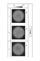
- FIG. 29 shows images obtained by thermography of a first heating object 591, a second heating object 592, and a third heating object 593 heated using the test apparatus 500.
- FIG. 30 shows, as a comparative experiment, an image obtained by thermography of a heating object 590 heated using a commercial microwave oven.
- microwaves are considered to be constantly irradiated from the outer periphery of the object 590 to be heated while being multiple-reflected inside the oven. heating was occurring.
- the temperature difference between the outer peripheral portion and the central portion was 33°C.
- the heat generated in the outer peripheral portion of the object 590 to be heated does not show an equal temperature distribution along the circumference, and a low temperature portion was generated as indicated by a circle 599 in the figure. This indicates that there is no uniformity in the standing wave distribution formed by the reflection of microwaves on the metal housing. This suggested that there was no reproducibility of heating.
- the first heating object 591, the second heating object 592, and the third heating object 593 heated using the test apparatus 500 all have On the other hand, the outer peripheral portion was slightly hot, but the temperature difference was about 7°C, and the uniformity was high. As described above, it has been shown that this heating method, which aims to suppress power reflection, can achieve highly uniform heating, as opposed to the heating method that actively uses power reflection, as typified by microwave ovens. rice field.
- Example 8 The microwave irradiation device 7 of the seventh embodiment was analyzed by numerical simulation.
- the metal housing 682 is made of aluminum and has dimensions of 1320 mm in length, 350 mm in width and 400 mm in height.
- a conveyor 661 made of resin was provided so as to pass through the inside of the metal housing 682 .
- the position of the second loop antenna 640b arranged in the center was used as the coordinate origin, and the electric field intensity formed between each antenna was analyzed.
- FIG. 32 shows the result of analyzing the electric field intensity formed between each antenna in the model shown in FIG.
- the positions of ⁇ 333 mm, 0 mm, and 333 mm indicated by dashed lines indicate the positions where the loop antennas are arranged.
- FIG. 33 shows the analysis result of the electric field intensity with respect to the irradiation distance from the oscillator in the waveguide, which was performed as a comparative analysis.
- antinodes and nodes of a standing wave are alternately formed in the waveguide due to reflection from the metal housing.
- the electric field strength is twice the oscillator output and at nodal locations the electric field strength is zero. That is, there is a large difference in electric field intensity depending on the location.
- the electric field strength distribution was highly uniform without nodes.
- FIG. 34 shows the analysis result of heat generation distribution of the heating object 690 when the heating object 690 filled with 150 g of potato salad in a cup made of polypropylene (PP) material is heated.
- the left figure shows a cross section along the conveying direction by the conveyor 661
- the right figure shows a cross section in a direction orthogonal to the conveying direction by the conveyor 661 .
- a uniform heat generation distribution in the object 690 to be heated was confirmed.
Landscapes
- Life Sciences & Earth Sciences (AREA)
- Engineering & Computer Science (AREA)
- Wood Science & Technology (AREA)
- Zoology (AREA)
- Chemical & Material Sciences (AREA)
- Food Science & Technology (AREA)
- Polymers & Plastics (AREA)
- Physics & Mathematics (AREA)
- Electromagnetism (AREA)
- Constitution Of High-Frequency Heating (AREA)
- Treatments Of Macromolecular Shaped Articles (AREA)
- Physical Or Chemical Processes And Apparatus (AREA)
Abstract
Description
第1の実施形態について図面を参照して説明する。本実施形態は、マイクロ波照射装置に関する。本実施形態のマイクロ波照射装置は、被照射物に対してマイクロ波を照射して、被照射物を内部加熱するように構成されている。被照射物は、これに限らないが、例えば食品である。したがって、このマイクロ波照射装置やそれを用いたマイクロ波の照射方法は、例えば包装食品を含む食品の製造に用いられ得る。マイクロ波照射装置は、搬送装置を有し、複数の被照射物が次々と搬送されて、次々と加熱される。マイクロ波を放射する複数の指向性のアンテナが、搬送方向に沿って並べられている。
図1Aは、本実施形態に係るマイクロ波照射装置1の構成例の概略を模式的に示す正面図であり、図1Bは、本実施形態に係るマイクロ波照射装置1の構成例の概略を模式的に示す平面図である。これら図に示すように、マイクロ波照射装置1は、加熱対象物であってマイクロ波が照射される被照射物90を搬送する搬送装置60を備える。搬送装置60は、例えば、ベルト61とローラ62とを備える。ベルト61は、ローラ62に掛けられている。ローラ62は、図示しないモータによって回転し、ベルト61を長手軸方向に移動させる。被照射物90は、ベルト61に載せられて、ベルト61の移動によって搬送方向91に搬送される。搬送装置60の搬送方向91上流側には、被照射物90をベルト61の上に次々と供給する供給装置84が設けられている。搬送装置60の搬送方向91下流側には、搬送された被照射物90をベルト61から搬出する搬出装置86が設けられている。
本実施形態のマイクロ波照射装置1の動作について説明する。発振器10は、マイクロ波の周波数に応じた高周波電力を出力する。その周波数は、これに限らないが、例えば、2.45GHz又は915MHzといったものや、450MHzといったものである。この発振器10から出力された高周波電力は、給電器具20を介してアンテナ40に供給される。アンテナ40は、この給電に基づいて、マイクロ波を指向性照射軸45の方向に照射する。
第2の実施形態について説明する。ここでは、第1の実施形態との相違点について説明し、同一の部分については、同一の符号を付してその説明を省略する。
本実施形態のマイクロ波照射装置2を用いて、対向する2つのアンテナ40によって両側から被照射物90に均等にマイクロ波を照射して、被照射物90を加熱する例について上述したが、加熱方法はこれに限らない。
第3の実施形態について説明する。ここでは、第1の実施形態との相違点について説明し、同一の部分については、同一の符号を付してその説明を省略する。
第4の実施形態について図面を参照して説明する。本実施形態は、マイクロ波照射装置に関する。本実施形態のマイクロ波照射装置は、被照射物に対してマイクロ波を照射して、被照射物を内部加熱するように構成されている。被照射物は、これに限らないが、例えば食品である。
第5の実施形態について説明する。ここでは、第4の実施形態との相違点について説明し、同一の部分については、同一の符号を付してその説明を省略する。本実施形態のマイクロ波照射装置は、例えば食品といった被照射物に対してマイクロ波を照射して、被照射物を内部加熱するように構成されている。マイクロ波照射装置は、搬送装置を有し、複数の被照射物が次々と搬送されて、次々と加熱される。
第6の実施形態について説明する。ここでは、第4の実施形態との相違点について説明し、同一の部分については、同一の符号を付してその説明を省略する。
第7の実施形態について説明する。ここでは、第5の実施形態との相違点について説明し、同一の部分については、同一の符号を付してその説明を省略する。
第8の実施形態について説明する。ここでは、第7の実施形態との相違点について説明し、同一の部分については、同一の符号を付してその説明を省略する。図16は、第8の実施形態に係るマイクロ波照射装置8の構成例の概略を模式的に示す平面図である。この図に示すように、第8の実施形態に係るマイクロ波照射装置8は、第7の実施形態に係るマイクロ波照射装置7と同様であるが、一部のアンテナ40の向きが変更されており、そのアンテナ40の指向性照射軸45が搬送方向91に沿っていない点が第7の実施形態に係るマイクロ波照射装置7と異なる。
上述の実施形態に係るマイクロ波照射装置による加熱の均一性を、加熱対象物を容器詰めされたポテトサラダとして評価した。
評価には、図13を参照して説明した第6の実施形態に係るマイクロ波照射装置6と同様の構成を有する試験装置を用いた。この試験装置100の構成例の概略を図17に示す。試験装置100は、発振器110と、金属筐体182内に配置された2つのループアンテナ140及び食品保持台166とを有する。
電界強度の数値シミュレーションの結果、2つのループアンテナ140間では、図5に示したような均一な電界が得られた。
上述の実施形態に係るマイクロ波照射装置による加熱特性を、加熱対象物を食品モデルとしての熱インジケータゲルとして、さらに評価した。
図20は、評価に用いた試験装置200の構成例の概略を示す。この試験装置200は、図4を参照して説明した第2の実施形態のマイクロ波照射装置2における対向する一対のアンテナ40を含む部分の構成や、図13を参照して説明した第6の実施形態のマイクロ波照射装置6の構成に相当する。また、この状況は、図15A及び図15Bを参照して説明した第7の実施形態において、搬送装置60によって被照射物90が2つのアンテナ40の中間に位置している状態に相当する。試験装置200の構成は、以下のとおりとした。
図21は、試験装置200を用いて出力150 Wとして加熱した後の食品モデル290の写真を示す。図21において、上段は加熱時間が4分の場合であり、下段は加熱時間が6分の場合である。図21において、左列は、食品モデル290を上から撮影した食品モデル290の表面の様子を示す。この図において、左右方向が第1のループアンテナ240a及び第2のループアンテナ240bの指向性照射軸の方向である。図21において、右列は、左列の一点鎖線で示す線で切断した食品モデル290の縦断面の様子を示す。
上述の実験例2では、第1のループアンテナ240a及び第2のループアンテナ240bから等距離の位置における加熱状況について検討した。本実験例では、第1のループアンテナ240a及び第2のループアンテナ240bの何れか一方側に偏った位置における加熱状況について検討した。この状況は、図1B等を参照して説明した第1の実施形態又は図6を参照して説明した第3の実施形態の状態や、図15B等を参照して説明した第7の実施形態において搬送装置60によって被照射物90が2つのアンテナ40に対して偏った位置に搬送された状態に相当する。
図23は、本実験例の実施状況の概略を示す図である。本実験例では、図20に示した試験装置200を用いた。食品モデル290を、第1のループアンテナ240aから食品モデル290の中心までの距離が56.5 mmになる位置に配置した。試験装置200の出力を150 Wとし、5分間加熱した。
図24は、加熱後の食品モデル290の写真を示す。図24において、左の写真は、食品モデル290を上から撮影した食品モデル290の表面の様子を示す。この図において、左右方向が第1のループアンテナ240a及び第2のループアンテナ240bの指向性照射軸の方向であり、左側が食品モデル290に近い第1のループアンテナ240a側であり、右側が食品モデル290から離れている第2のループアンテナ240b側である。図24において、右の写真は、左の写真に示した一点鎖線の位置で切断した食品モデル290の縦断面の様子を示す。同様に、左側が食品モデル290に近い第1のループアンテナ240a側であり、右側が食品モデル290から離れている第2のループアンテナ240b側である。
上述の実験例2の状況について、数値シミュレーションによる解析を行った。
解析には、熱連成解析ソフトであるCST STUDIO SUITE(ダッソー・システムズ社製)を用い、熱と電磁界の連成解析を行った。図20に示した試験装置200の解析モデルを構築した。加熱対象物は、ポリプロピレン(PP)材のカップに詰めた市販のポテトサラダ150 gを模擬したものとした。加熱対象物の電気特性は、市販のポテトサラダの実測値に基づいて、比誘電率εr = 51、導電率ρ = 1.2 s/m、誘電正接tanδ = 0.95とした。
図25A及び図25Bは、熱連成解析結果を示す。図25Aは、解析結果を斜視図で示し、図25Bは、加熱対象物390の中心を通り第1のループアンテナ340a及び第2のループアンテナ340bの指向性照射軸に対して垂直な断面を示す。図21に示した実験例2の結果と同様に、加熱対象物390の中心部が強く発熱して高温になった。本数値解析の結果は、実験結果とよく一致した。この数値解析には信頼性があることが確認された。
図1B等を参照して説明した第1の実施形態のマイクロ波照射装置1、図7を参照して説明した第4の実施形態のマイクロ波照射装置4、及び図10A等を参照して説明した第5の実施形態のマイクロ波照射装置5に相当する装置構成における、数値シミュレーションによる解析を行った。
実験例4と同様の解析を行った。解析結果を示す図26Aに示されるように、図1Bを参照して説明した第1の実施形態のマイクロ波照射装置1における1つのアンテナ40を含む部分、あるいは、図7を参照して説明した第4の実施形態のマイクロ波照射装置4及び図10A等を参照して説明した第5の実施形態のマイクロ波照射装置5に相当するモデルを構築して解析を行った。すなわち、このモデルでは、保持台466上に配置した加熱対象物490の片側のみにループアンテナ440を配置した。加熱対象物490は、実験例4の加熱対象物390と同様とした。
図26A及び図26Bは、熱連成解析結果を示す。図26Aに示すように、ループアンテナ440から加熱対象物490の中心までの距離が166.5 mmであるとき、加熱対象物490の外周部のうち、特にループアンテナ440に近い側が発熱することがわかった。加熱対象物に対してアンテナを片側のみに配置し、加熱対象物に対して非対称にマイクロ波を照射することによって、アンテナ側の加熱対象物の外周部を選択的に加熱可能であることが明らかになった。
加熱方法を検討する実験を行った。
図20に示した試験装置200を用いて、ポリプロピレン(PP)材のカップに市販のポテトサラダ140 gを充填して充填後シールしない試料を加熱対象物として、実験を行った。加熱条件を以下のようにした。まず、加熱対象物を第1のループアンテナ240aと第2のループアンテナ240bとの中間位置に配置して、出力150 Wで2.5分間加熱した。加熱後、インターバルとして1.5分間放置した。続いて、加熱対象物を第1のループアンテナ240aから加熱対象物の中心までの距離が56.5 mmとなる位置に配置して、出力150 Wで2.5分間加熱した。この間の加熱対象物の温度を、光ファイバー温度計を用いて測定した。
図27は、加熱対象物の中心部(実線)と外周部(破線)との温度測定の結果を示す。加熱対象物を第1のループアンテナ240aと第2のループアンテナ240bとの中間位置に配置した場合、加熱対象物の中心部が外周部よりもより加熱され、2.5分加熱後の温度は、中心部で70℃、外周部で45℃となった。1.5分間のインターバル期間での温度低下はあまりなく、インターバル期間終了時の温度は、中心部で67℃、外周部で45℃となった。その後、加熱対象物を第1のループアンテナ240a側に寄せて加熱したところ、加熱対象物の外周部が中心部よりもより加熱され、2.5分加熱後の温度は、中心部で73℃、外周部で100℃となった。
図15B等を参照して説明した第7の実施形態のマイクロ波照射装置7に相当する試験装置を作製して、加熱対象物を搬送しながら加熱した場合の加熱特性を評価した。
図28は、本実験例に係る試験装置500の構成例の概略を示す図である。試験装置500は、電磁波を遮蔽する第1の金属筐体582aと、第2の金属筐体582bと、第3の金属筐体582cとを備える。第1の金属筐体582aは、アルミニウム材で形成し、その寸法は、搬送方向に沿う長さ440 mm、搬送方向に直交する幅350 mm、高さ400 mmとした。第1の金属筐体582a内を通るように、幅140 mmの樹脂製のコンベア561を設けた。第1の金属筐体582aのコンベア561の入口部分に第1の金属筐体582aと接続するように第2の金属筐体582bを設け、第1の金属筐体582aのコンベア561の出口部分に第1の金属筐体582aと接続するように第3の金属筐体582cを設けた。第2の金属筐体582b及び第3の金属筐体582cのそれぞれは、アルミニウム材で形成し、その寸法は、長さ220 mm、幅248 mm、高さ80 mmとした。
図29は、試験装置500を用いて加熱した第1の加熱対象物591、第2の加熱対象物592及び第3の加熱対象物593のサーモグラフィーで得られた画像を示す。また、図30は、比較実験として、業務用電子レンジを用いて加熱した加熱対象物590のサーモグラフィーで得られた画像を示す。
第7の実施形態のマイクロ波照射装置7について、数値シミュレーションによる解析を行った。
図31に示す第7の実施形態に係るマイクロ波照射装置7のモデルを作製した。このモデルにおいて、金属筐体682は、アルミニウム材とし、その寸法は、長さ1320 mm、幅350 mm、高さ400 mmとした。金属筐体682内を通るように、樹脂製のコンベア661を設けた。金属筐体682内には、コンベア661が貫通するように、3つのループアンテナである第1のループアンテナ640a、第2のループアンテナ640b及び第3のループアンテナ640cを設けた。これらループアンテナは、いずれもアルミニウム材であり、外寸を214 mm×111 mmとした。第1のループアンテナ640aの第1の給電部653a、第2のループアンテナ640bの第2の給電部653b、及び第3のループアンテナ640cの第3の給電部653cのそれぞれに給電する電力の周波数は450 MHz(波長λ = 666 mm)とした。各ループアンテナ間の距離は、333 mm(λ/2)とした。
図32は、図31に示すモデルにおいて各アンテナ間に形成される電界強度を解析した結果を示す。この図において、破線で示す-333 mm、0 mm、333 mmの位置は、ループアンテナが配置されている位置を示す。また、図33は、比較解析として行った導波管内で発振器からの照射距離に対する電界強度の解析結果を示す。
Claims (27)
- 被照射物を保持する保持具と、
発振器と導通するように構成された給電器具と、
前記給電器具を介した導通による給電によって照射面内の照射源からマイクロ波を照射するように構成されている指向性のアンテナと
を備えるマイクロ波照射装置。 - 前記保持具は、前記被照射物を搬送方向に搬送する搬送装置であり、
前記マイクロ波照射装置は、前記搬送方向に沿って配置されている複数の前記アンテナを有するアンテナ群を備える、
請求項1に記載のマイクロ波照射装置。 - 前記アンテナは、前記照射源から照射されるマイクロ波の指向性照射軸が、前記搬送装置を構成するマイクロ波を反射する構造物と交差しないように配置されている、請求項2に記載のマイクロ波照射装置。
- 前記アンテナ群は、前記搬送装置を挟んで両側に配置された前記複数のアンテナを有する、請求項2又は3に記載のマイクロ波照射装置。
- 前記アンテナは、前記照射面が開口面であるループアンテナである、請求項2乃至4の何れかに記載のマイクロ波照射装置。
- 前記ループアンテナの前記開口面の両側に配置された複数の前記搬送装置を有する搬送装置群を備える、請求項5に記載のマイクロ波照射装置。
- 前記アンテナは、前記照射面が開口面であるループアンテナである、請求項1に記載のマイクロ波照射装置。
- 前記ループアンテナと前記保持具との少なくとも何れか一方は、前記照射源から照射される前記マイクロ波の指向性照射軸に沿って移動し、前記ループアンテナと前記保持具との相対的な位置関係を変化させるように構成されている、請求項7に記載のマイクロ波照射装置。
- 前記保持具は、前記開口面を貫通して設けられている、
請求項7又は8に記載のマイクロ波照射装置。 - 前記保持具は、前記開口面を貫通する方向に移動するように構成されている、請求項9に記載のマイクロ波照射装置。
- 前記ループアンテナは、前記照射源から照射される前記マイクロ波の指向性照射軸が、前記保持具を構成する前記マイクロ波を反射する構造物と交わらないように配置されている、請求項7乃至10の何れかに記載のマイクロ波照射装置。
- 前記照射源から照射される前記マイクロ波の指向性照射軸に沿って設けられた複数の前記ループアンテナを有するアンテナ群を備える、請求項7乃至11の何れかに記載のマイクロ波照射装置。
- 複数の前記ループアンテナを有するアンテナ群を備え、
前記保持具は、前記アンテナ群の複数の前記開口面を貫通して設けられている、
請求項7乃至12の何れかに記載のマイクロ波照射装置。 - 前記保持具は、前記開口面を貫通する方向に移動するように構成されている、請求項13に記載のマイクロ波照射装置。
- 前記アンテナ群を構成する前記ループアンテナは、前記照射源から照射される前記マイクロ波の指向性照射軸が、少なくとも、当該ループアンテナの前記開口面と向き合う、前記アンテナ群を構成する他のループアンテナの前記開口面との間に存在する前記保持具を構成する前記マイクロ波を反射する構造物と交わらないように配置されている、請求項12乃至14の何れかに記載のマイクロ波照射装置。
- 給電によって照射面内の照射源からマイクロ波を照射するように構成された指向性のアンテナによって被照射物にマイクロ波を照射するマイクロ波の照射方法であって、
前記被照射物の両側に配置された複数の前記アンテナから同時に均等にマイクロ波を照射することを含む、照射方法。 - 前記複数のアンテナに一つの発振器から並列に給電する、請求項16に記載の照射方法。
- 前記被照射物の両側又は片側に配置された前記アンテナから不均等にマイクロ波を照射することをさらに含む請求項16又は17に記載の照射方法。
- 前記均等にマイクロ波を照射することは、前記被照射物から等距離に対向して配置された一対の前記アンテナから照射強度が等しいマイクロ波を前記被照射物に照射することを含む、請求項18に記載の照射方法。
- 前記不均等にマイクロ波を照射することは、
前記一対のアンテナの一方からマイクロ波を前記被照射物に照射することと、
前記一対のアンテナの他方からマイクロ波を前記被照射物に照射することと
を含む、請求項19に記載の照射方法。 - 前記不均等にマイクロ波を照射することは、照射強度が等しいマイクロ波を照射している前記一対のアンテナの一方に前記被照射物を近づけることを含む、請求項19に記載の照射方法。
- 搬送装置によって前記被照射物を搬送方向に搬送することをさらに含み、
前記搬送装置における第1の位置において第1の位置から等距離に対向して一対の前記アンテナが配置されており、前記均等にマイクロ波を照射することは、前記第1の位置にある前記被照射物に対して、前記一対のアンテナの各々から照射強度が等しいマイクロ波を照射することを含み、
前記搬送装置における第2の位置において第2の位置の少なくとも片側に前記アンテナが配置されており、前記不均等にマイクロ波を照射することは、前記第2の位置にある前記被照射物に対して、前記片側の前記アンテナからマイクロ波を照射することを含む、
請求項18に記載の照射方法。 - マイクロ波を照射して食品を加熱することを含む食品の製造方法であって、
前記マイクロ波の照射は、給電によって照射面内の照射源からマイクロ波を照射するように構成された指向性のアンテナによって行われる、食品の製造方法。 - 前記マイクロ波の照射は、前記食品の両側に配置された複数の前記アンテナに一つの発振器から並列に給電して当該複数のアンテナから同時に均等にマイクロ波を照射することを含む、請求項23に記載の食品の製造方法。
- 前記食品の両側又は片側に配置された前記アンテナから不均等にマイクロ波を照射することをさらに含む、請求項24に記載の食品の製造方法。
- 前記食品が包装食品である、請求項23乃至25の何れかに記載の食品の製造方法。
- 前記マイクロ波の照射は、
発振器と導通するように構成された給電器具と、
前記給電器具を介した導通による給電によってマイクロ波を照射するように構成された、前記指向性のアンテナである前記照射面が開口面であるループアンテナと
を用いて行われる、請求項23に記載の食品の製造方法。
Priority Applications (3)
| Application Number | Priority Date | Filing Date | Title |
|---|---|---|---|
| EP22767025.4A EP4307833A4 (en) | 2021-03-12 | 2022-03-04 | MICROWAVE IRRADIATION DEVICE |
| CN202280020635.0A CN116982404A (zh) | 2021-03-12 | 2022-03-04 | 微波照射装置 |
| US18/464,871 US20230422362A1 (en) | 2021-03-12 | 2023-09-11 | Microwave irradiation device |
Applications Claiming Priority (4)
| Application Number | Priority Date | Filing Date | Title |
|---|---|---|---|
| JP2021040835 | 2021-03-12 | ||
| JP2021040836 | 2021-03-12 | ||
| JP2021-040836 | 2021-03-12 | ||
| JP2021-040835 | 2021-03-12 |
Related Child Applications (1)
| Application Number | Title | Priority Date | Filing Date |
|---|---|---|---|
| US18/464,871 Continuation US20230422362A1 (en) | 2021-03-12 | 2023-09-11 | Microwave irradiation device |
Publications (1)
| Publication Number | Publication Date |
|---|---|
| WO2022191068A1 true WO2022191068A1 (ja) | 2022-09-15 |
Family
ID=83227849
Family Applications (1)
| Application Number | Title | Priority Date | Filing Date |
|---|---|---|---|
| PCT/JP2022/009403 Ceased WO2022191068A1 (ja) | 2021-03-12 | 2022-03-04 | マイクロ波照射装置 |
Country Status (4)
| Country | Link |
|---|---|
| US (1) | US20230422362A1 (ja) |
| EP (1) | EP4307833A4 (ja) |
| TW (1) | TW202301902A (ja) |
| WO (1) | WO2022191068A1 (ja) |
Cited By (1)
| Publication number | Priority date | Publication date | Assignee | Title |
|---|---|---|---|---|
| WO2024095425A1 (ja) * | 2022-11-02 | 2024-05-10 | 東洋製罐グループホールディングス株式会社 | マイクロ波照射装置 |
Citations (5)
| Publication number | Priority date | Publication date | Assignee | Title |
|---|---|---|---|---|
| JPS5216656U (ja) * | 1975-07-25 | 1977-02-05 | ||
| JPS58176896A (ja) * | 1982-04-10 | 1983-10-17 | 豊田合成株式会社 | マイクロ波加熱装置 |
| JPS60262386A (ja) * | 1984-06-07 | 1985-12-25 | 松下電器産業株式会社 | 高周波加熱装置 |
| JPH07130463A (ja) * | 1993-10-28 | 1995-05-19 | New Japan Radio Co Ltd | 電子レンジ |
| JP2020021678A (ja) | 2018-08-02 | 2020-02-06 | 日本無線株式会社 | マイクロ波加熱装置 |
Family Cites Families (2)
| Publication number | Priority date | Publication date | Assignee | Title |
|---|---|---|---|---|
| WO2017035604A1 (en) * | 2015-09-03 | 2017-03-09 | Commonwealth Scientific And Industrial Research Organisation | Microwave heating apparatus and method of heating |
| DE102017121731A1 (de) * | 2017-09-19 | 2019-03-21 | Muegge Gmbh | Vorrichtung zur Behandlung eines Produkts mit Mikrowellen |
-
2022
- 2022-03-04 EP EP22767025.4A patent/EP4307833A4/en active Pending
- 2022-03-04 TW TW111108046A patent/TW202301902A/zh unknown
- 2022-03-04 WO PCT/JP2022/009403 patent/WO2022191068A1/ja not_active Ceased
-
2023
- 2023-09-11 US US18/464,871 patent/US20230422362A1/en active Pending
Patent Citations (5)
| Publication number | Priority date | Publication date | Assignee | Title |
|---|---|---|---|---|
| JPS5216656U (ja) * | 1975-07-25 | 1977-02-05 | ||
| JPS58176896A (ja) * | 1982-04-10 | 1983-10-17 | 豊田合成株式会社 | マイクロ波加熱装置 |
| JPS60262386A (ja) * | 1984-06-07 | 1985-12-25 | 松下電器産業株式会社 | 高周波加熱装置 |
| JPH07130463A (ja) * | 1993-10-28 | 1995-05-19 | New Japan Radio Co Ltd | 電子レンジ |
| JP2020021678A (ja) | 2018-08-02 | 2020-02-06 | 日本無線株式会社 | マイクロ波加熱装置 |
Non-Patent Citations (1)
| Title |
|---|
| See also references of EP4307833A4 |
Cited By (1)
| Publication number | Priority date | Publication date | Assignee | Title |
|---|---|---|---|---|
| WO2024095425A1 (ja) * | 2022-11-02 | 2024-05-10 | 東洋製罐グループホールディングス株式会社 | マイクロ波照射装置 |
Also Published As
| Publication number | Publication date |
|---|---|
| US20230422362A1 (en) | 2023-12-28 |
| EP4307833A1 (en) | 2024-01-17 |
| EP4307833A4 (en) | 2025-01-22 |
| TW202301902A (zh) | 2023-01-01 |
Similar Documents
| Publication | Publication Date | Title |
|---|---|---|
| US3946188A (en) | Microwave heating apparatus with browning feature | |
| EP2920533B1 (en) | Apparatus and method for dehydration using microwave radiation | |
| EP2852251A1 (en) | Microwave heating device | |
| CN102308668B (zh) | 微波加热装置 | |
| KR101934155B1 (ko) | 온도검출장치 및 열처리장치 | |
| WO2005023013A2 (en) | Apparatus and method for heating objects with microwaves | |
| KR101907235B1 (ko) | 차폐된 마이크로파-방사에너지측정-안테나를 포함한 열처리 장치 | |
| US20230422362A1 (en) | Microwave irradiation device | |
| JP2022140343A (ja) | マイクロ波照射装置 | |
| JP2022140342A (ja) | マイクロ波照射装置 | |
| TWI826392B (zh) | 用於以微波處理產品的裝置 | |
| JP3960612B2 (ja) | マイクロ波照射処理装置 | |
| JP4658995B2 (ja) | マイクロ波連続加熱装置 | |
| JP7711535B2 (ja) | マイクロ波照射装置 | |
| WO2024095425A1 (ja) | マイクロ波照射装置 | |
| WO2017119093A1 (ja) | 加熱用照射装置 | |
| CN104470020A (zh) | 微波加热暨干燥装置 | |
| KR20230025792A (ko) | 마이크로파 처리 장치 | |
| JP2518670B2 (ja) | マイクロ波加熱システム、方法並びに装置 | |
| JP2024100492A (ja) | マイクロ波照射装置 | |
| JPS6366038B2 (ja) | ||
| JP2024011760A (ja) | マイクロ波照射装置、マイクロ波照射方法及び食品の製造方法 | |
| JP2025095649A (ja) | マイクロ波照射装置及びマイクロ波照射方法 | |
| JP2025095650A (ja) | 加熱装置及び加熱方法 | |
| Hassan et al. | Hyperthermia Brain Cancer Treatment Using a Wideband Antenna with an Elliptic Reflector |
Legal Events
| Date | Code | Title | Description |
|---|---|---|---|
| 121 | Ep: the epo has been informed by wipo that ep was designated in this application |
Ref document number: 22767025 Country of ref document: EP Kind code of ref document: A1 |
|
| WWE | Wipo information: entry into national phase |
Ref document number: 202280020635.0 Country of ref document: CN |
|
| WWE | Wipo information: entry into national phase |
Ref document number: 2022767025 Country of ref document: EP |
|
| NENP | Non-entry into the national phase |
Ref country code: DE |
|
| ENP | Entry into the national phase |
Ref document number: 2022767025 Country of ref document: EP Effective date: 20231012 |