WO2022191297A1 - 負極用材料、負極、リチウム二次電池、及び、負極用材料の製造方法 - Google Patents
負極用材料、負極、リチウム二次電池、及び、負極用材料の製造方法 Download PDFInfo
- Publication number
- WO2022191297A1 WO2022191297A1 PCT/JP2022/010722 JP2022010722W WO2022191297A1 WO 2022191297 A1 WO2022191297 A1 WO 2022191297A1 JP 2022010722 W JP2022010722 W JP 2022010722W WO 2022191297 A1 WO2022191297 A1 WO 2022191297A1
- Authority
- WO
- WIPO (PCT)
- Prior art keywords
- negative electrode
- layer
- lithium
- secondary battery
- lithium secondary
- Prior art date
- Legal status (The legal status is an assumption and is not a legal conclusion. Google has not performed a legal analysis and makes no representation as to the accuracy of the status listed.)
- Ceased
Links
Images


Classifications
-
- H—ELECTRICITY
- H01—ELECTRIC ELEMENTS
- H01M—PROCESSES OR MEANS, e.g. BATTERIES, FOR THE DIRECT CONVERSION OF CHEMICAL ENERGY INTO ELECTRICAL ENERGY
- H01M4/00—Electrodes
- H01M4/02—Electrodes composed of, or comprising, active material
- H01M4/13—Electrodes for accumulators with non-aqueous electrolyte, e.g. for lithium-accumulators; Processes of manufacture thereof
- H01M4/134—Electrodes based on metals, Si or alloys
-
- H—ELECTRICITY
- H01—ELECTRIC ELEMENTS
- H01M—PROCESSES OR MEANS, e.g. BATTERIES, FOR THE DIRECT CONVERSION OF CHEMICAL ENERGY INTO ELECTRICAL ENERGY
- H01M4/00—Electrodes
- H01M4/02—Electrodes composed of, or comprising, active material
- H01M4/36—Selection of substances as active materials, active masses, active liquids
- H01M4/362—Composites
- H01M4/366—Composites as layered products
-
- H—ELECTRICITY
- H01—ELECTRIC ELEMENTS
- H01M—PROCESSES OR MEANS, e.g. BATTERIES, FOR THE DIRECT CONVERSION OF CHEMICAL ENERGY INTO ELECTRICAL ENERGY
- H01M10/00—Secondary cells; Manufacture thereof
- H01M10/05—Accumulators with non-aqueous electrolyte
- H01M10/052—Li-accumulators
-
- H—ELECTRICITY
- H01—ELECTRIC ELEMENTS
- H01M—PROCESSES OR MEANS, e.g. BATTERIES, FOR THE DIRECT CONVERSION OF CHEMICAL ENERGY INTO ELECTRICAL ENERGY
- H01M10/00—Secondary cells; Manufacture thereof
- H01M10/05—Accumulators with non-aqueous electrolyte
- H01M10/056—Accumulators with non-aqueous electrolyte characterised by the materials used as electrolytes, e.g. mixed inorganic/organic electrolytes
- H01M10/0564—Accumulators with non-aqueous electrolyte characterised by the materials used as electrolytes, e.g. mixed inorganic/organic electrolytes the electrolyte being constituted of organic materials only
- H01M10/0566—Liquid materials
- H01M10/0569—Liquid materials characterised by the solvents
-
- H—ELECTRICITY
- H01—ELECTRIC ELEMENTS
- H01M—PROCESSES OR MEANS, e.g. BATTERIES, FOR THE DIRECT CONVERSION OF CHEMICAL ENERGY INTO ELECTRICAL ENERGY
- H01M10/00—Secondary cells; Manufacture thereof
- H01M10/42—Methods or arrangements for servicing or maintenance of secondary cells or secondary half-cells
- H01M10/44—Methods for charging or discharging
- H01M10/446—Initial charging measures
-
- H—ELECTRICITY
- H01—ELECTRIC ELEMENTS
- H01M—PROCESSES OR MEANS, e.g. BATTERIES, FOR THE DIRECT CONVERSION OF CHEMICAL ENERGY INTO ELECTRICAL ENERGY
- H01M4/00—Electrodes
- H01M4/02—Electrodes composed of, or comprising, active material
- H01M4/04—Processes of manufacture in general
- H01M4/0402—Methods of deposition of the material
- H01M4/0404—Methods of deposition of the material by coating on electrode collectors
-
- H—ELECTRICITY
- H01—ELECTRIC ELEMENTS
- H01M—PROCESSES OR MEANS, e.g. BATTERIES, FOR THE DIRECT CONVERSION OF CHEMICAL ENERGY INTO ELECTRICAL ENERGY
- H01M4/00—Electrodes
- H01M4/02—Electrodes composed of, or comprising, active material
- H01M4/36—Selection of substances as active materials, active masses, active liquids
- H01M4/38—Selection of substances as active materials, active masses, active liquids of elements or alloys
- H01M4/381—Alkaline or alkaline earth metals elements
- H01M4/382—Lithium
-
- H—ELECTRICITY
- H01—ELECTRIC ELEMENTS
- H01M—PROCESSES OR MEANS, e.g. BATTERIES, FOR THE DIRECT CONVERSION OF CHEMICAL ENERGY INTO ELECTRICAL ENERGY
- H01M4/00—Electrodes
- H01M4/02—Electrodes composed of, or comprising, active material
- H01M4/36—Selection of substances as active materials, active masses, active liquids
- H01M4/38—Selection of substances as active materials, active masses, active liquids of elements or alloys
- H01M4/40—Alloys based on alkali metals
- H01M4/405—Alloys based on lithium
-
- H—ELECTRICITY
- H01—ELECTRIC ELEMENTS
- H01M—PROCESSES OR MEANS, e.g. BATTERIES, FOR THE DIRECT CONVERSION OF CHEMICAL ENERGY INTO ELECTRICAL ENERGY
- H01M4/00—Electrodes
- H01M4/02—Electrodes composed of, or comprising, active material
- H01M4/62—Selection of inactive substances as ingredients for active masses, e.g. binders, fillers
- H01M4/628—Inhibitors, e.g. gassing inhibitors, corrosion inhibitors
-
- H—ELECTRICITY
- H01—ELECTRIC ELEMENTS
- H01M—PROCESSES OR MEANS, e.g. BATTERIES, FOR THE DIRECT CONVERSION OF CHEMICAL ENERGY INTO ELECTRICAL ENERGY
- H01M4/00—Electrodes
- H01M4/02—Electrodes composed of, or comprising, active material
- H01M2004/021—Physical characteristics, e.g. porosity, surface area
-
- H—ELECTRICITY
- H01—ELECTRIC ELEMENTS
- H01M—PROCESSES OR MEANS, e.g. BATTERIES, FOR THE DIRECT CONVERSION OF CHEMICAL ENERGY INTO ELECTRICAL ENERGY
- H01M4/00—Electrodes
- H01M4/02—Electrodes composed of, or comprising, active material
- H01M2004/026—Electrodes composed of, or comprising, active material characterised by the polarity
- H01M2004/027—Negative electrodes
-
- H—ELECTRICITY
- H01—ELECTRIC ELEMENTS
- H01M—PROCESSES OR MEANS, e.g. BATTERIES, FOR THE DIRECT CONVERSION OF CHEMICAL ENERGY INTO ELECTRICAL ENERGY
- H01M2300/00—Electrolytes
- H01M2300/0017—Non-aqueous electrolytes
- H01M2300/0025—Organic electrolyte
- H01M2300/0028—Organic electrolyte characterised by the solvent
- H01M2300/0034—Fluorinated solvents
-
- H—ELECTRICITY
- H01—ELECTRIC ELEMENTS
- H01M—PROCESSES OR MEANS, e.g. BATTERIES, FOR THE DIRECT CONVERSION OF CHEMICAL ENERGY INTO ELECTRICAL ENERGY
- H01M4/00—Electrodes
- H01M4/02—Electrodes composed of, or comprising, active material
- H01M4/36—Selection of substances as active materials, active masses, active liquids
- H01M4/48—Selection of substances as active materials, active masses, active liquids of inorganic oxides or hydroxides
- H01M4/485—Selection of substances as active materials, active masses, active liquids of inorganic oxides or hydroxides of mixed oxides or hydroxides for inserting or intercalating light metals, e.g. LiTi2O4 or LiTi2OxFy
-
- H—ELECTRICITY
- H01—ELECTRIC ELEMENTS
- H01M—PROCESSES OR MEANS, e.g. BATTERIES, FOR THE DIRECT CONVERSION OF CHEMICAL ENERGY INTO ELECTRICAL ENERGY
- H01M4/00—Electrodes
- H01M4/02—Electrodes composed of, or comprising, active material
- H01M4/36—Selection of substances as active materials, active masses, active liquids
- H01M4/58—Selection of substances as active materials, active masses, active liquids of inorganic compounds other than oxides or hydroxides, e.g. sulfides, selenides, tellurides, halogenides or LiCoFy; of polyanionic structures, e.g. phosphates, silicates or borates
-
- Y—GENERAL TAGGING OF NEW TECHNOLOGICAL DEVELOPMENTS; GENERAL TAGGING OF CROSS-SECTIONAL TECHNOLOGIES SPANNING OVER SEVERAL SECTIONS OF THE IPC; TECHNICAL SUBJECTS COVERED BY FORMER USPC CROSS-REFERENCE ART COLLECTIONS [XRACs] AND DIGESTS
- Y02—TECHNOLOGIES OR APPLICATIONS FOR MITIGATION OR ADAPTATION AGAINST CLIMATE CHANGE
- Y02E—REDUCTION OF GREENHOUSE GAS [GHG] EMISSIONS, RELATED TO ENERGY GENERATION, TRANSMISSION OR DISTRIBUTION
- Y02E60/00—Enabling technologies; Technologies with a potential or indirect contribution to GHG emissions mitigation
- Y02E60/10—Energy storage using batteries
Definitions
- the present invention relates to a negative electrode material, a negative electrode, a lithium secondary battery, and a method for producing a negative electrode material.
- Patent Document 1 discloses a negative electrode in which lithium phosphorous oxynitride is formed on the surface of a lithium metal layer.
- Patent Document 2 discloses a negative electrode in which an ion-conducting material having a thickness of at least 0.5 ⁇ m is formed on the surface of a lithium metal layer.
- Patent Document 3 discloses a negative electrode in which a sulfide-based inorganic material is formed on the surface of a lithium metal layer.
- a negative electrode material is provided.
- the negative electrode material described above is used, for example, in the negative electrode of a lithium secondary battery containing a non-aqueous electrolyte.
- the negative electrode material described above includes, for example, a first layer containing lithium metal as a negative electrode active material.
- the negative electrode material described above includes, for example, a second layer disposed on at least one surface of the first layer.
- the second layer has, for example, the general formula M x A y (M is a kind of element selected from the group consisting of Al, In, Mg, Ag, Si and Sn, and A is , O, N, P and F, wherein 0.3 ⁇ x/y ⁇ 3.).
- the second layer has a thickness of, for example, 100 nm or less.
- the second layer may have a thickness of less than 50 nm.
- A may be an element selected from the group consisting of O and N.
- a negative electrode is provided in a second aspect of the present invention.
- the negative electrode includes, for example, the negative electrode material according to the first aspect.
- the negative electrode described above includes, for example, a negative electrode current collector that holds a negative electrode material.
- the second layer may be arranged so as to entirely cover the first layer arranged in contact with the negative electrode current collector.
- the second layer may be arranged such that a portion of the second layer is in contact with the negative electrode current collector.
- a third aspect of the present invention provides a lithium secondary battery.
- the lithium secondary battery described above includes, for example, the negative electrode according to the second aspect described above.
- the lithium secondary battery described above includes, for example, a positive electrode.
- the lithium secondary battery described above includes, for example, a non-aqueous electrolyte.
- the non-aqueous electrolyte may contain a cyclic carbonate having a fluorine atom.
- the ratio of the cyclic carbonate having a fluorine atom to the total non-aqueous electrolyte may be 20 mol % or more and 80 mol % or less.
- the fluorine atom-containing cyclic carbonate may include fluoroethylene carbonate (FEC) or difluoroethylene carbonate (DFEC).
- the negative electrode may contain an alloy of lithium and the element represented by M contained in the second layer after the lithium secondary battery has been charged and discharged at least once.
- the second layer may contain nitrogen as the element represented by A.
- the negative electrode may contain lithium nitride after the lithium secondary battery has been charged and discharged at least once.
- a fourth aspect of the present invention provides a method of manufacturing a negative electrode for use in a lithium secondary battery containing a non-aqueous electrolyte.
- the method includes providing a first layer comprising, for example, lithium metal as the negative electrode active material.
- the method includes, for example, forming a second layer on at least one side of the first layer.
- the second layer has, for example, the general formula M x A y (M is a kind of element selected from the group consisting of Al, In, Mg, Ag, Si and Sn, A is O , N, P and F, wherein 0.3 ⁇ x/y ⁇ 3.).
- the second layer has a thickness of, for example, 100 nm or less.
- FIG. 4 shows the results of a cycle characteristic test of the symmetrical cell of Example 1.
- FIG. 3 shows the results of a cycle characteristic test of the symmetrical cell of Comparative Example 1.
- FIG. 4 shows the results of a cycle characteristic test of the symmetrical cell of Example 2.
- the negative electrode material used for the negative electrode of the lithium secondary battery containing the non-aqueous electrolyte comprises at least a first layer and a second layer is taken as an example.
- the first layer includes lithium metal as a negative electrode active material.
- the second layer is arranged on at least one surface of the first layer.
- the above second layer has the general formula MxAy (M is an element selected from the group consisting of Al, In, Mg, Ag, Si and Sn, A is O, N, P and F 0.3 ⁇ x/y ⁇ 3), which is a kind of element selected from the group.
- the second layer has a thickness of 100 nm or less.
- the second layer is made of an inorganic material having a specific composition and thickness, so that a second layer with excellent electrical conductivity or ionic conductivity can be obtained. This suppresses the overvoltage of the lithium secondary voltage during charging and discharging. Moreover, according to the present embodiment, since the second layer is arranged on the surface of the first layer, direct contact between the lithium metal of the first layer and the non-aqueous electrolyte is suppressed. This suppresses reduction of the non-aqueous electrolyte by lithium metal. As a result, the generation of dendrite-like lithium (sometimes referred to as Li dendrite) during charging and discharging of the lithium secondary battery is suppressed. In addition, by suppressing the generation of Li dendrites, the cycle characteristics of the lithium secondary battery are improved. For example, the cycle life of lithium secondary batteries is increased.
- deterioration in battery performance is suppressed, and stability during battery operation is improved.
- the non-aqueous electrolyte contains a fluorine atom-containing cyclic carbonate
- deterioration in battery performance is greatly suppressed, and stability during battery operation is greatly improved.
- FIG. 1 schematically shows an example of the internal structure of the storage battery 100.
- FIG. FIG. 1 may be an example of a cross-sectional view of the storage battery 100 .
- details of the storage battery 100 will be described by taking as an example a case where the storage battery 100 is a coin-type non-aqueous secondary battery.
- the storage battery 100 accumulates electrical energy. Moreover, the storage battery 100 supplies the stored electrical energy to the outside.
- a power source can be created by connecting a plurality of storage batteries 100 in series and/or in parallel.
- the storage battery 100 is a lithium secondary battery.
- Storage battery 100 contains a non-aqueous electrolyte as an electrolyte.
- the storage battery 100 includes, as a negative electrode active material, at least one of lithium metal (sometimes referred to as metallic lithium), an alloy of lithium metal and other metals, and an intermetallic compound of lithium metal and other metals. (the term lithium metal, etc. is sometimes used as a generic term for these).
- Lithium metal, etc. has a very low potential and a very large theoretical capacity, so by using lithium metal etc. as the negative electrode active material, an excellent secondary battery can be obtained. In particular, by using lithium metal as the negative electrode active material, a very excellent secondary battery can be obtained.
- the structure of the negative electrode of the storage battery 100 inhibits dendrite generation and/or growth. This achieves stabilization of the negative electrode.
- the composition of the non-aqueous electrolyte achieves stabilization of the negative electrode.
- the structure of the negative electrode of the storage battery 100 and the composition of the non-aqueous electrolyte achieve stabilization of the negative electrode.
- the storage battery 100 includes a positive case 112 , a negative case 114 , a spacer 116 and a metal spring 118 .
- the storage battery 100 also includes a positive electrode 120 , a separator 130 , a negative electrode 140 and a non-aqueous electrolyte 150 .
- the positive electrode 120 has a positive electrode current collector 122 and a positive electrode active material layer 124 .
- the negative electrode 140 has a negative electrode current collector 142 , a negative electrode active material layer 144 and a coating layer 146 .
- the positive electrode case 112 and the negative electrode case 114 are made of, for example, a conductive material having a disk-like thin plate shape.
- a space is formed inside the positive case 112 and the negative case 114 by assembling the positive case 112 and the negative case 114 .
- a metal spring 118 , a positive electrode 120 , a separator 130 , a negative electrode 140 and a non-aqueous electrolyte 150 are housed inside the space formed by the positive electrode case 112 and the negative electrode case 114 .
- the positive electrode 120 , the separator 130 and the negative electrode 140 are fixed inside the positive electrode case 112 and the negative electrode case 114 by the repulsive force of the metal spring 118 .
- the spacer 116 holds, for example, a laminate of the positive electrode 120 , the separator 130 and the negative electrode 140 inside the space formed by the positive electrode case 112 and the negative electrode case 114 .
- Spacers 116 may be used to position the stack of positive electrode 120 , separator 130 and negative electrode 140 .
- the spacer 116 may seal the gap formed between the positive case 112 and the negative case 114 .
- Spacer 116 may comprise an insulating material. In this embodiment, spacer 116 insulates positive case 112 and negative case 114 .
- a relatively large space is formed between the spacer 116 and the laminate of the positive electrode 120, the separator 130 and the negative electrode 140 for the purpose of facilitating drawing and explanation.
- the size of the space between the spacer 116 and the laminate of the positive electrode 120, the separator 130 and the negative electrode 140 can be adjusted as appropriate. can.
- the spacer 116 may fix the laminate by contacting the spacer 116 with the laminate of the positive electrode 120 , the separator 130 , and the negative electrode 140 .
- the material of the metal spring 118 is not particularly limited as long as it is a conductive substance.
- the shape and size of the metal spring 118 are not particularly limited.
- Metal spring 118 may be a washer.
- the positive electrode current collector 122 holds the positive electrode active material layer 124 .
- the material of the positive electrode current collector 122 is not particularly limited as long as it is an electronic conductor that is chemically stable in the storage battery 100 .
- Examples of materials for the positive electrode current collector 122 include aluminum, stainless steel, nickel, titanium, and alloys thereof.
- Examples of the shape of the positive electrode current collector 122 include foil, mesh, punched metal, expanded metal, and the like.
- the thickness of the positive electrode current collector 122 is not particularly limited, it is preferably 5 to 200 ⁇ m. The thickness of the positive electrode current collector 122 may be 6 to 20 ⁇ m.
- the positive electrode active material layer 124 is formed on at least one surface of the positive electrode current collector 122 .
- the thickness of the positive electrode active material layer 124 may be 1 to 300 ⁇ m or 2 to 200 ⁇ m per side of the positive electrode current collector 122 .
- the positive electrode active material layer 124 contains, for example, a positive electrode active material and a binder (sometimes referred to as a binder).
- the positive electrode active material layer 124 may contain a conductive aid.
- the positive electrode active material layer 124 is formed by applying a paste containing a material constituting the positive electrode active material layer 124 and an organic solvent on at least one surface of the positive electrode current collector 122, and drying the paste. formed by
- the type of the organic solvent is not particularly limited, examples of the organic solvent include N-methylpyrrolidone (NMP).
- NMP N-methylpyrrolidone
- the positive electrode active material layer 124 is formed by mixing the materials that constitute the positive electrode active material layer 124 and molding it into a sheet shape, and press-bonding the sheet-like mixture to at least one surface of the positive electrode current collector 122 . It is formed by
- the positive electrode active material can be a substance capable of intercalating and deintercalating lithium ions and having a potential higher than that of the metallic lithium negative electrode, which is the negative electrode active material. Insertion-type transition metal oxides are used.
- positive electrode active materials include (i) LiMnO 2 , LiNiO 2 , LiCoO 2 , Li(Mn x Ni 1-x )O 2 , Li(Mn x Co 1-x )O 2 , Li(Ni y Co 1-y ) O 2 , layered oxides such as Li(Mn x Ni y Co 1-x-y )O 2 , (ii) Li 2 MnO 3 —LiNiO 2 , Li 2 MnO 3 —LiCoO 2 , Li 2 MnO 3 —Li solid solutions such as ( NiyCo1 -y ) O2 , (iii) Li2MnSiO4 , Li2NiSiO4 , Li2CoSiO4
- a conversion-type high-capacity positive electrode active material may be used as the positive electrode active material.
- Examples of conversion-type high-capacity positive electrode active materials include sulfur, sulfur compounds, iron fluoride, and transition metal oxides.
- the conversion-type positive electrode active material does not contain lithium in the initial state. Therefore, by combining a positive electrode containing a conversion-type positive electrode active material and a negative electrode containing lithium metal as a negative electrode active material, the energy density of the non-aqueous electrolyte secondary battery is greatly improved.
- the binder binds materials (for example, positive electrode active material, conductive aid, etc.) constituting the positive electrode active material layer 124 and retains the electrode shape of the positive electrode 120 .
- the binder is not particularly limited as long as it is chemically stable in storage battery 100 .
- a thermoplastic resin may be used as the binder, or a thermosetting resin may be used.
- binders include polyethylene, polypropylene, polyvinylidene fluoride (PVDF), polytetrafluoroethylene (PTFE), polyacrylic acid, and styrene-butadiene rubber.
- the conductive aid reduces the resistance of the positive electrode 120 .
- the conductive aid is not particularly limited as long as it is chemically stable in the storage battery 100 and has desired electronic conductivity.
- an inorganic material may be used, or an organic material may be used.
- a carbon material is exemplified as the conductive aid. Examples of carbon materials include graphite, carbon black (such as acetylene black and ketjen black), coke, amorphous carbon, carbon fibers, carbon nanotubes, and graphene. These conductive aids may be used alone, or two or more conductive aids may be combined.
- separator 130 separates positive electrode 120 and negative electrode 140 .
- the separator 130 ensures ionic conductivity between the positive electrode 120 and the negative electrode 140 by, for example, retaining an electrolyte.
- materials for the separator 130 include polyethylene, polypropylene, ethylene-propylene copolymer, glass, and composites thereof.
- the shape of the separator 130 include a microporous film, a nonwoven fabric, and a filter.
- the separator 130 may be a laminate of these films or the like.
- the thickness of the separator 130 is not particularly limited, it is preferably 10 to 50 ⁇ m.
- the aperture ratio of the separator 130 is not particularly limited, it is preferably 30 to 70%.
- the negative electrode current collector 142 holds the negative electrode active material layer 144 .
- a material that does not react with lithium is used for the negative electrode current collector 142 .
- materials for the negative electrode current collector 142 include copper, aluminum, stainless steel, nickel, titanium, and alloys thereof.
- the negative electrode current collector 142 may include a resin support layer and a metal layer disposed on the surface of the support layer. Examples of the above resin include polyethylene, polypropylene, polyethylene terephthalate, and polyimide.
- the metal layer may be a layer of copper, aluminum, stainless steel, nickel, titanium or alloys thereof.
- the metal layers may include layers of copper, aluminum, stainless steel, nickel, titanium or alloys thereof.
- the metal layer may be a foil or a plated layer.
- Examples of the shape of the negative electrode current collector 142 include foil, mesh, punched metal, expanded metal, and the like.
- the thickness of the negative electrode current collector 142 is not particularly limited, but may be 5 to 200 ⁇ m.
- the thickness of the negative electrode current collector 142 is preferably 6 to 20 ⁇ m.
- the negative electrode active material layer 144 is formed on at least one surface of the negative electrode current collector 142 .
- the negative electrode active material layer 144 may be formed on only one surface of the sheet-shaped, film-shaped, or foil-shaped negative electrode current collector 142 , or may be formed on both surfaces of the negative electrode current collector 142 .
- the thickness of the negative electrode active material layer 144 may be 1 to 200 ⁇ m or 4 to 100 ⁇ m per side of the negative electrode current collector 142 .
- the negative electrode active material layer 144 includes lithium metal (sometimes referred to as metallic lithium), alloys of lithium metal and other metals, and lithium metal and other metals as the negative electrode active material. At least one intermetallic compound is included.
- the negative electrode active material layer 144 may be a layer made of lithium or the like described above.
- the negative electrode active material layer 144 may contain lithium metal as a negative electrode active material.
- the negative electrode active material layer 144 may be a layer made of lithium metal.
- the negative electrode active material layer 144 may be a lithium metal foil.
- the thickness of the lithium metal foil may be from 1 to 200 ⁇ m, from 2 to 100 ⁇ m, preferably from 4 to 50 ⁇ m.
- the thickness and/or mass of the lithium metal foil may be determined according to the content of the positive electrode active material in the positive electrode active material layer 124 .
- the negative electrode active material layer 144 is formed by crimping a sheet-like, film-like, or foil-like material that constitutes the negative electrode active material layer 144 to at least one surface of the negative electrode current collector 142. be done.
- the anode active material layer 144 is formed by (i) physical vapor deposition (PVD) such as sputtering, evaporation, ion plating, (ii) chemical vapor deposition (CVD), (iii) ) is formed by depositing a material forming the negative electrode active material layer 144 on at least one surface of the negative electrode current collector 142 by an atomic layer deposition method (ALD method) or the like.
- PVD physical vapor deposition
- CVD chemical vapor deposition
- the coating layer 146 is arranged on at least one surface of the negative electrode active material layer 144 .
- the coating layer 146 is disposed on one of the two surfaces of the sheet-like, film-like, or foil-like negative electrode active material layer 144 opposite to the surface in contact with the negative electrode current collector 142 .
- the surface in contact with the negative electrode current collector 142 may not be provided with the coating layer 146 .
- the coating layer 146 may be arranged so as to entirely cover the negative electrode active material layer 144 arranged in contact with the negative electrode current collector 142 .
- coating layer 146 is arranged such that a portion of coating layer 146 is in contact with negative electrode current collector 142 .
- the size of the coating layer 146 may be larger than the size of the negative electrode active material layer 144 . Thereby, the coating layer 146 can entirely cover the negative electrode active material layer 144 arranged in contact with the negative electrode current collector 142 .
- the coating layer 146 is arranged on both of the two main surfaces of the sheet-like, film-like or foil-like negative electrode active material layer 144 .
- a coating layer 146 is interposed between the negative electrode current collector 142 and the negative electrode active material layer 144 .
- the coating layer 146 can entirely cover the negative electrode active material layer 144 disposed on the negative electrode current collector 142 .
- the coating layer 146 has the general formula M x A y (M is an element selected from the group consisting of Al, In, Mg, Ag, Si and Sn, A is O, N , P and F, wherein 0.3 ⁇ x/y ⁇ 3).
- M is an element selected from the group consisting of Al, In, Mg, Ag, Si and Sn
- A is O, N , P and F, wherein 0.3 ⁇ x/y ⁇ 3).
- the coating layer 146 contains Al, In, Mg, Ag, Si, or Sn, thereby suppressing the generation and/or growth of Li dendrites.
- the non-aqueous electrolyte 150 may contain an organic compound having a fluorine atom as a liquid organic solvent.
- Al, In, Mg, Ag, Si, or Sn contained in the compound represented by the above general formula M x A y and fluorine atoms contained in the organic compound used as the organic solvent of the non-aqueous electrolyte 150 interaction more effectively suppresses the generation and/or growth of Li dendrites.
- the coating layer 146 preferably contains Al and/or In. That is, M in the general formula is preferably an element selected from the group consisting of Al and In. The inclusion of Al and/or In in the coating layer 146 effectively suppresses the generation and/or growth of dendritic lithium.
- Coating layer 146 preferably comprises an oxide or nitride. That is, A in the general formula is preferably an element selected from the group consisting of O and N. When the compound represented by the general formula M x A y is an oxide, a coating layer 146 with excellent strength can be obtained. As a result, the thickness of the coating layer 146 can be reduced, so that the coating layer 146 having excellent electrical conductivity or ionic conductivity can be obtained. In this case, a coating layer 146 having excellent lithium ion conductivity is obtained.
- Coating layer 146 preferably includes at least one of Al 2 O 3 , In 2 O 3 , AlN and InN.
- the coating layer 146 is preferably a layer made of Al 2 O 3 , In 2 O 3 , AlN or InN. As a result, the coating layer 146 can be obtained which has excellent electrical conductivity or ion conductivity and can effectively suppress the generation and/or growth of dendritic lithium.
- the coating layer 146 has a thickness of 100 nm or less.
- the thickness of the coating layer 146 may be less than 50 nm, 30 nm or less, 20 nm or less, or 10 nm or less. Thereby, a coating layer 146 having excellent electrical conductivity or ionic conductivity is obtained.
- the coating layer 146 is formed by, for example, (i) physical vapor deposition (PVD) such as sputtering, vapor deposition, ion plating, (ii) chemical vapor deposition (CVD), (iii) atomic layer deposition ( ALD method) is used to deposit a material forming the coating layer 146 on at least one surface of the negative electrode active material layer 144 .
- PVD physical vapor deposition
- CVD chemical vapor deposition
- ALD method atomic layer deposition
- the coating layer 146 If the electrical conductivity or ionic conductivity of the coating layer 146 is low, the coating layer 146 itself acts as a resistive layer, causing a large overvoltage during charging and discharging. As a result, the performance of storage battery 100 is degraded. According to this embodiment, the coating layer 146 has a specific composition and thickness, and the coating layer 146 has excellent electrical or ionic conductivity. As a result, occurrence of a large overvoltage during charging and discharging of the storage battery 100 is prevented.
- Elements forming the compound represented by the general formula M x A y included in the coating layer 146 may react with lithium included in the storage battery 100 during charging and discharging of the storage battery 100 .
- the negative electrode 140 may contain reaction products of lithium and the elements that make up the compound represented by the general formula M x A y .
- Coating layer 146 may contain a reaction product between lithium and an element constituting a compound represented by the general formula M x A y .
- the above reaction products may form a film.
- the reaction products described above form, for example, a film on the surface of the coating layer 146 .
- an alloy of lithium contained in the storage battery 100 and elements forming a compound represented by the general formula M x A y may be generated.
- the alloy may be a solid solution or an intermetallic compound.
- the above alloy may be an alloy of lithium and an element represented by M contained in a compound represented by the general formula M x A y .
- the negative electrode 140 is an alloy of lithium and the element represented by M contained in the compound represented by the general formula M x A y .
- the coating layer 146 may contain an alloy of lithium and an element represented by M contained in a compound represented by the general formula M x A y .
- the above alloys may form a coating.
- lithium nitride may be generated during charging and discharging of the storage battery 100 .
- the negative electrode 140 may contain lithium nitride.
- Coating layer 146 may include lithium nitride. The lithium nitride described above may form a coating.
- the non-aqueous electrolyte 150 achieves ionic conduction between the positive electrode active material and the negative electrode active material via the electrolyte contained in the non-aqueous electrolyte 150 .
- a known organic electrolyte can be used as the non-aqueous electrolyte 150 .
- Non-aqueous electrolyte 150 includes, for example, a lithium salt or sodium salt as an electrolyte and a polar solvent.
- a polar solvent may be an organic solvent.
- Lithium salts include (i) inorganic lithium salts such as LiClO 4 , LiPF 6 , LiBF 4 , LiAsF 6 and LiSbF 6 , (ii) LiCF 3 SO 3 , LiCF 3 CO 2 , Li 2 C 2 F 4 (SO 3 ) 2 , LiN(FSO 2 ) 2 , LiN(CF 3 SO 2 ) 2 , LiC(CF 3 SO 2 ) 3 , LiC n F 2n+1 SO 3 (n is an integer of 2 or more), LiN(R f Examples include organic lithium salts such as OSO 2 ) 2 (R f is a substituted or unsubstituted fluoroalkyl group). LiN(FSO 2 ) 2 is sometimes referred to as LiFSI. LiN(CF 3 SO 2 ) 2 is
- lithium salts may be used alone, or two or more lithium salts may be combined.
- the lithium salt one or more of lithium hexafluorophosphate (LiPF 6 ), lithium bisfluorosulfonylimide (LiFSI), lithium bistrifluoromethanesulfonylimide (LiTFSI), LiBF 4 (lithium borofluoride) is used. preferably.
- organic solvent is not particularly limited as long as it dissolves the lithium salt described above and does not easily cause side reactions such as decomposition in the voltage range used as a battery.
- organic solvents include (i) cyclic carbonates such as ethylene carbonate, propylene carbonate and butylene carbonate, (ii) chain carbonates such as dimethyl carbonate, diethyl carbonate and methyl ethyl carbonate, and (iii) chain esters such as methyl propionate.
- cyclic esters such as ⁇ -butyrolactone
- chain ethers such as dimethoxyethane, diethyl ether, 1,3-dioxolane, diglyme, triglyme, tetraglyme
- dioxane tetrahydrofuran, 2-methyltetrahydrofuran.
- nitriles such as acetonitrile, propionitrile and methoxypropionitrile
- sulfites such as ethylene glycol sulfite.
- the above organic solvents may be used alone, or two or more lithium salts may be combined.
- one or more of carbonate compounds and ether compounds are preferably used.
- the above carbonate compounds include propylene carbonate, ethylene carbonate (EC), dimethyl carbonate (DMC), ethylmethyl carbonate (EMC), diethyl carbonate (DEC), fluoroethylene carbonate (FEC), fluoroethylene methyl carbonate (FEMC), and the like.
- Examples of the above ether compounds include 1,2-dimethoxyethane (DME).
- the carbonate compound and/or ether compound described above are more likely to be reductively decomposed by the lithium metal of the negative electrode active material layer 144 than other organic solvents.
- the lithium metal of the negative electrode active material layer 144 is covered with the coating layer 146, lithium Reductive decomposition of the non-aqueous electrolyte 150 by metal is suppressed.
- the above organic solvent may contain an organic compound having a fluorine atom.
- the above organic solvent preferably contains a cyclic carbonate having a fluorine atom.
- the organic solvent preferably contains one or more of the various organic solvents described above and a cyclic carbonate having a fluorine atom.
- Fluorinated ethylene carbonate is exemplified as a cyclic carbonate having a fluorine atom.
- fluoroethylene carbonate include fluoroethylene carbonate (FEC), difluoroethylene carbonate (DFEC), fluoroethylene methyl carbonate (FEMC), and the like.
- Other examples of organic compounds having a fluorine atom include fluorinated ethers and glyme fluorides.
- the organic solvent preferably contains one or more of the various organic solvents described above and fluoroethylene carbonate.
- the ratio of the cyclic carbonate having a fluorine atom to the total organic solvent contained in the non-aqueous electrolyte 150 is preferably 20 mol % or more.
- the ratio of the cyclic carbonate having a fluorine atom to the total organic solvent used in the non-aqueous electrolyte 150 may be 20 mol% or more and 80% or less, or may be 25 mol% or more and 70 mol% or less, It may be 30 mol % or more and 60 mol % or less.
- the ratio of the cyclic carbonate having a fluorine atom to the entire non-aqueous electrolyte 150 may be 20 mol % or more.
- the ratio of the number of moles of the cyclic carbonate having a fluorine atom to the total number of moles of the electrolyte and the organic solvent contained in the non-aqueous electrolyte 150 is 20 mol % or more.
- the above ratio may be 20 mol % or more and 80 mol % or less, 25 mol % or more and 70 mol % or less, or 30 mol % or more and 60 mol % or less.
- the cyclic carbonate having a plurality of types of fluorine atoms with respect to the total number of moles of the electrolyte and the organic solvent used in the non-aqueous electrolyte 150 may be 20 mol % or more.
- the above ratio may be 20 mol % or more and 80 mol % or less, 25 mol % or more and 70 mol % or less, or 30 mol % or more and 60 mol % or less.
- the non-aqueous electrolytic solution 150 contains a cyclic carbonate having a fluorine atom as at least part of the main organic solvent, thereby suppressing reductive decomposition of the carbonate compound and ether compound contained in the organic solvent.
- fluorinated ethylene carbonate contains highly electronegative fluorine atoms. Therefore, when the organic solvent contains fluoroethylene carbonate, the reductive decomposition of the carbonate compound and ether compound contained in the organic solvent is greatly suppressed.
- LiPF 6 is used as the electrolyte, and a mixed solvent of ethylene carbonate (EC) and diethyl carbonate (DEC) is used as the polar solvent.
- EC ethylene carbonate
- DEC diethyl carbonate
- a cyclic carbonate having a fluorine atom may be added to the above mixed solvent.
- fluoroethylene carbonate is added to the above mixed solvent.
- LiTFSI is used as the electrolyte
- a mixed solvent of ethylene carbonate (EC) and diethyl carbonate (DEC) is used as the polar solvent.
- EC ethylene carbonate
- DEC diethyl carbonate
- a cyclic carbonate having a fluorine atom may be added to the above mixed solvent.
- fluoroethylene carbonate is added to the above mixed solvent.
- LiBF4 is used as the electrolyte and a mixed solvent of propylene carbonate (PC) and ethyl methyl carbonate (EMC) is used as the polar solvent.
- PC propylene carbonate
- EMC ethyl methyl carbonate
- a cyclic carbonate having a fluorine atom may be added to the above mixed solvent.
- fluoroethylene carbonate is added to the above mixed solvent.
- the concentration of the lithium salt in the non-aqueous electrolyte 150 is not particularly limited, but is 0.1 to 5.0. It may be within the range of mol/L. The concentration of the lithium salt may be in the range of 0.5-4.0 mol/L, or in the range of 0.7-1.5 mol/L.
- the negative electrode 140 includes a laminate of a negative electrode active material layer 144 containing lithium metal and a coating layer 146 made of a compound represented by the general formula M x A y . This suppresses reduction of the non-aqueous electrolyte by lithium metal. In addition, generation of dendritic lithium is suppressed during charging and discharging of the lithium secondary battery.
- the nonaqueous electrolyte 150 is propylene carbonate, ethylene carbonate (EC), dimethyl carbonate (DMC), ethylmethyl carbonate (EMC), diethyl carbonate (DEC), fluoroethylene carbonate (FEC), difluoroethylene carbonate (DFEC),
- FEMC fluoroethylene methyl carbonate
- DME 1,2-dimethoxyethane
- the negative electrode 140 includes a laminate of a negative electrode active material layer 144 and a coating layer 146; , ethyl methyl carbonate (EMC), diethyl carbonate (DEC), fluoroethylene carbonate (FEC), difluoroethylene carbonate (DFEC), fluoroethylene methyl carbonate (FEMC), and 1,2-dimethoxyethane (DME) and (ii) a fluorine atom-containing cyclic carbonate, reduction of the non-aqueous electrolyte by lithium metal is effectively suppressed. In addition, the generation of dendritic lithium during charging and discharging of the lithium secondary battery is effectively suppressed.
- EMC ethyl methyl carbonate
- DEC diethyl carbonate
- FEC fluoroethylene carbonate
- DFEC difluoroethylene carbonate
- FEMC fluoroethylene methyl carbonate
- DME 1,2-dimethoxyethane
- the storage battery 100 may be an example of a lithium secondary battery.
- the negative electrode active material layer 144 may be an example of the first layer.
- Coating layer 146 may be an example of a second layer.
- a laminate of the first layer and the second layer may be an example of a negative electrode material.
- the details of the storage battery 100 have been described by taking as an example the case where the storage battery 100 is a coin-type secondary battery.
- the type, structure, etc. of the storage battery 100 are not limited to this embodiment.
- the storage battery 100 may be a cylindrical battery comprising a wound electrode body in which a positive electrode, a separator and a negative electrode are spirally wound.
- the storage battery 100 may be a laminate type battery in which a laminated electrode body in which a positive electrode and a negative electrode are alternately laminated with a separator sandwiched therebetween is sealed with a laminate.
- the details of the storage battery 100 have been described by taking as an example the case where the negative electrode 140 has the negative electrode current collector 142 and the negative electrode active material layer 144 .
- the negative electrode of the storage battery 100 is not limited to this embodiment.
- the storage battery 100 may not include the negative electrode current collector 142 .
- an example of the storage battery 100 has been described using the case where the non-aqueous electrolyte 150 is used as the electrolyte of the storage battery 100 .
- the electrolyte of storage battery 100 is not limited to this embodiment.
- a gel electrolyte may be used as the electrolyte of storage battery 100 .
- a gel electrolyte can be obtained, for example, by adding a known gelling agent to the non-aqueous electrolyte 150 described above.
- known ionic liquids may be used as the electrolyte of storage battery 100 .
- FIG. 2 schematically shows an example of a method for manufacturing the storage battery 100.
- step 212 the step may be abbreviated as S
- the sheet-like negative electrode current collector 142 and the lithium metal foil as the negative electrode active material layer 144 are separated. be prepared.
- the negative electrode current collector 142 and lithium metal foil are laminated.
- a lithium metal foil is pressure-bonded to at least one surface of the negative electrode current collector 142 .
- a coating layer having a thickness of 100 nm or less is formed on at least part of the surface of the lithium metal foil pressed to the negative electrode current collector 142 on the side opposite to the surface in contact with the negative electrode current collector 142.
- 146 is laminated.
- the coating layer 146 is formed, for example, by physical vapor deposition (PVD), chemical vapor deposition (CVD), or atomic layer deposition (ALD). At this time, the coating layer 146 is formed to entirely cover the surface of the lithium metal foil.
- the storage battery 100 is assembled. Specifically, first, the positive electrode 120 , the separator 130 , the negative electrode 140 , the spacer 116 and the metal spring 118 are arranged inside the positive electrode case 112 and the negative electrode case 114 . A non-aqueous electrolyte 150 is injected into the positive electrode case 112 and the negative electrode case 114 . After that, the positive electrode case 112 and the negative electrode case 114 are enclosed to obtain the storage battery 100 .
- the coating layer 146 is formed on the surface of the lithium metal foil.
- the procedure for manufacturing the negative electrode 140 is not limited to this embodiment.
- the lithium metal foil having the coating layer 146 is pressed against the negative electrode current collector 142 .
- a "symmetrical cell” is used to evaluate the performance of the negative electrode.
- two equivalent electrodes of equal material, mass and thickness are arranged symmetrically within the cell.
- various modifications or improvements may be made to the examples below, and the storage battery 100 is not limited to the examples below.
- a negative electrode was produced by the following procedure.
- a Cu foil having a thickness of 10 ⁇ m was prepared as the negative electrode current collector 142 .
- a lithium metal foil having a thickness of 20 ⁇ m was prepared as the negative electrode active material layer 144 .
- a lithium metal foil was crimped onto one surface of the Cu foil.
- Al 2 O 3 was deposited on the surface of the lithium metal foil by PVD method to form an Al 2 O 3 layer as the coating layer 146 .
- the thickness of the Al 2 O 3 layer was 10 nm.
- a positive electrode was produced by the same procedure as that for the negative electrode. As a result, a positive electrode was obtained in which the Cu current collector, the Li layer and the Al 2 O 3 layer were laminated in this order.
- polyethylene having a thickness of 16 ⁇ m was prepared as the separator 130.
- a non-aqueous electrolytic solution containing a mixed solvent of ethyl methyl carbonate and fluoroethylene carbonate and lithium hexafluorophosphate was prepared.
- Lithium hexafluorophosphate: fluoroethylene carbonate: ethyl methyl carbonate was 12.6:18.0:69.4 (% by volume).
- the mol % of fluoroethylene carbonate with respect to the entire mixed solvent was 20 mol % or more.
- a coin-type battery was produced using the above-described positive electrode, negative electrode, separator, and non-aqueous electrolyte. This produced a symmetrical cell for evaluation.
- Example 2 Example 1, except that the mixing ratio of lithium hexafluorophosphate: fluoroethylene carbonate: ethyl methyl carbonate in the non-aqueous electrolyte was 12.8: 22.1: 65.1 (% by volume). A coin-type battery was produced by the same procedure. This produced a symmetrical cell for evaluation.
- a negative electrode was produced by the following procedure.
- a Cu foil having a thickness of 10 ⁇ m was prepared as the negative electrode current collector 142 .
- a lithium metal foil having a thickness of 20 ⁇ m was prepared as the negative electrode active material layer 144 .
- a negative electrode was obtained in which the Cu current collector and the Li layer were laminated in this order.
- a positive electrode was produced by the same procedure as for the negative electrode. As a result, a positive electrode was obtained in which the Cu current collector and the Li layer were laminated in this order. Also, the same separator and non-electrolyte solution as in Example 1 were prepared. A coin-type battery was produced in the same manner as in Example 1. This produced a symmetrical cell for evaluation.
- Example 1 Using the symmetric cell for evaluation produced in Example 1, the cycle characteristics of the symmetric cell were evaluated. Specifically, charging and discharging at a constant current were repeated 250 cycles, and voltage values during charging and discharging were recorded. The charge time per cycle was 1 hour and the discharge time per cycle was 1 hour.
- the charging conditions were a temperature of 23 [° C.], a current density of 1 [mA/cm 2 ], and a current value of 0.2 [mA].
- the discharge conditions were a temperature of 23 [° C.], a current density of 1 [mA/cm 2 ], and a current value of 0.2 [mA].
- Test Example 1 The results of Test Example 1 are shown in FIG.
- Example 1 two equivalent electrodes having the same material, mass and thickness are used as the positive and negative electrodes. Therefore, the operating voltage is 0 V, and the charge-discharge curve has a substantially symmetrical shape in the range where the electrodes are normal. In Test Example 1, it can be seen that the overvoltage is suppressed even after 500 hours have passed, and the negative electrode is stable.
- Test Example 2 Using the symmetric cell for evaluation produced in Comparative Example 1, the cycle characteristics of the symmetric cell were evaluated. Specifically, charging and discharging at a constant current were repeated 250 cycles, and voltage values during charging and discharging were recorded. The charge time per cycle was 1 hour and the discharge time per cycle was 1 hour. The conditions during charging and the conditions during discharging were the same as in Test Example 1.
- Test Example 2 The results of Test Example 2 are shown in FIG. In Test Example 2, it can be seen that an overvoltage occurs when 500 hours have passed.
- Test Example 3 Using the symmetric cell for evaluation produced in Example 2, the cycle characteristics of the symmetric cell were evaluated. Specifically, charging and discharging at a constant current were repeated 50 cycles, and voltage values during charging and discharging were recorded. The charge time per cycle was 1 hour and the discharge time per cycle was 1 hour. The conditions during charging and the conditions during discharging were the same as in Test Example 1.
- Fig. 5 shows the results of the cycle characteristics test.
- Test Example 3 it can be seen that the overvoltage is suppressed even after 100 hours have passed, and the negative electrode is stable.
- the negative electrode was stabilized by forming a 10 nm Al 2 O 3 layer on the surface of the lithium metal layer.
- Mg, Ag, Si and Sn, like Al can suppress the generation and/or growth of dendrite-like lithium.
- oxides, nitrides, fluorides and phosphides of these metals can form coating layers with excellent electrical or ionic conductivity, similar to Al 2 O 3 layers. Therefore, according to the present disclosure, by providing the negative electrode with a layer made of a compound represented by the general formula M x A y , deterioration of the performance of the lithium secondary battery is suppressed, and stability during battery operation is improved. demonstrated to do.
- Non-aqueous electrolyte 100 storage battery, 112 positive electrode case, 114 negative electrode case, 116 spacer, 118 metal spring, 120 positive electrode, 122 positive electrode current collector, 124 positive electrode active material layer, 130 separator, 140 negative electrode, 142 negative electrode current collector, 144 negative electrode active material layer , 146 Coating layer, 150
- Non-aqueous electrolyte 100 storage battery, 112 positive electrode case, 114 negative electrode case, 116 spacer, 118 metal spring, 120 positive electrode, 122 positive electrode current collector, 124 positive electrode active material layer, 130 separator, 140 negative electrode, 142 negative electrode current collector, 144 negative electrode active material layer , 146 Coating layer, 150
- Non-aqueous electrolyte 100 storage battery, 112 positive electrode case, 114 negative electrode case, 116 spacer, 118 metal spring, 120 positive electrode, 122 positive electrode current collector, 124 positive electrode active material layer, 130 separator, 140 negative electrode, 142 negative electrode current collector, 144 negative electrode active material layer , 146
Landscapes
- Chemical & Material Sciences (AREA)
- Chemical Kinetics & Catalysis (AREA)
- Electrochemistry (AREA)
- General Chemical & Material Sciences (AREA)
- Engineering & Computer Science (AREA)
- Manufacturing & Machinery (AREA)
- Composite Materials (AREA)
- Materials Engineering (AREA)
- Inorganic Chemistry (AREA)
- Physics & Mathematics (AREA)
- Condensed Matter Physics & Semiconductors (AREA)
- General Physics & Mathematics (AREA)
- Secondary Cells (AREA)
- Battery Electrode And Active Subsutance (AREA)
Abstract
非水電解液を含むリチウム二次電池の負極に用いられる負極用材料が、リチウム金属を負極活物質として含む第1層と、前記第1層の少なくとも一方の面に配される第2層とを備える。前記第2層は、一般式MxAy(Mは、Al、In、Mg、Ag、Si及びSnからなる群より選択される一種の元素であり、Aは、O、N、P及びFからなる群より選択される一種の元素であり、0.3<x/y<3である。)で表される化合物からなる。前記第2層は、100nm以下の厚さを有する。
Description
本発明は、負極用材料、負極、リチウム二次電池、及び、負極用材料の製造方法に関する。
特許文献1には、リチウム金属層の表面にリチウムリン酸窒化物が形成された負極が開示されている。特許文献2には、リチウム金属層の表面に少なくとも0.5μmの厚さを有するイオン導電性材料が形成された負極が開示されている。特許文献3には、リチウム金属層の表面に硫化物系無機材料が形成された負極が開示されている。
[先行技術文献]
[特許文献]
[特許文献1]米国特許第5314765号明細書
[特許文献2]米国特許第10461372号明細書
[特許文献3]米国特許第10833360号明細書
[先行技術文献]
[特許文献]
[特許文献1]米国特許第5314765号明細書
[特許文献2]米国特許第10461372号明細書
[特許文献3]米国特許第10833360号明細書
本発明の第1の態様においては、負極用材料が提供される。上記の負極用材料は、例えば、非水電解液を含むリチウム二次電池の負極に用いられる。上記の負極用材料は、例えば、リチウム金属を負極活物質として含む第1層を備える。上記の負極用材料は、例えば、第1層の少なくとも一方の面に配される第2層を備える。上記の負極用材料において、第2層は、例えば、一般式MxAy(Mは、Al、In、Mg、Ag、Si及びSnからなる群より選択される一種の元素であり、Aは、O、N、P及びFからなる群より選択される一種の元素であり、0.3<x/y<3である。)で表される化合物からなる。上記の負極用材料において、第2層は、例えば、100nm以下の厚さを有する。
上記の負極用材料において、第2層は、50nm未満の厚さを有してもよい。上記の負極用材料において、Aは、O及びNからなる群より選択される一種の元素であってよい。
本発明の第2の態様においては、負極が提供される。上記の負極は、例えば、上記の第1の態様に係る負極用材料を備える。上記の負極は、例えば、負極用材料を保持する負極集電体を備える。
上記の負極において、第2層は、負極集電体に接して配された第1層を全体的に覆うように配されてよい。上記の負極において、第2層は、第2層の一部が負極集電体に接するように配されてよい。
本発明の第3の態様においては、リチウム二次電池が提供される。上記のリチウム二次電池は、例えば、上記の第2の態様に係る負極を備える。上記のリチウム二次電池は、例えば、正極を備える。上記のリチウム二次電池は、例えば、非水電解液を備える。
上記のリチウム二次電池において、非水電解液は、フッ素原子を有する環状カーボネートを含んでよい。上記のリチウム二次電池において、非水電解液の全体に対する、フッ素原子を有する環状カーボネートの割合は、20モル%以上80モル%以下であってよい。上記のリチウム二次電池において、フッ素原子を有する環状カーボネートは、フルオロエチレンカーボネート(FEC)、又は、ジフルオロエチレンカーボネート(DFEC)を含んでよい。
上記のリチウム二次電池において、負極は、リチウム二次電池の充放電が少なくとも1回実施された後、リチウムと、第2層に含まれるMで表される元素との合金を含んでよい。上記のリチウム二次電池において、第2層は、Aで表される元素として窒素を含んでよい。上記のリチウム二次電池において、負極は、リチウム二次電池の充放電が少なくとも1回実施された後、窒化リチウムを含んでよい。
本発明の第4の態様においては、非水電解液を含むリチウム二次電池に用いられる負極を製造する方法が提供される。上記の方法は、例えば、リチウム金属を負極活物質として含む第1層を準備する段階を有する。上記の方法は、例えば、第1層の少なくとも一方の面に第2層を形成する段階を有する。上記の方法において、第2層は、例えば、一般式MxAy(Mは、Al、In、Mg、Ag、Si及びSnからなる群より選択される一種の元素であり、Aは、O、N、P及びFからなる群より選択される一種の元素であり、0.3<x/y<3である。)で表される化合物からなる。上記の方法において、第2層は、例えば、100nm以下の厚さを有する。
なお、上記の発明の概要は、本発明の必要な特徴の全てを列挙したものではない。また、これらの特徴群のサブコンビネーションもまた、発明となりうる。
本実施形態においては、非水電解液を含むリチウム二次電池の負極に用いられる負極用材料が、少なくとも第1層及び第2層を備える場合を例として、負極用材料、負極、リチウム二次電池、及び、負極用材料の製造方法の詳細が説明される。本実施形態において、上記の第1層は、リチウム金属を負極活物質として含む。上記の第2層は、第1層の少なくとも一方の面に配される。上記の第2層は、一般式MxAy(Mは、Al、In、Mg、Ag、Si及びSnからなる群より選択される一種 の元素であり、Aは、O、N、P及びFからなる群より選択される一種の元素であり、0.3<x/y<3 である。)で表される化合物からなる。また、上記の第2層は、100nm以下の厚さを有する。
本実施形態によれば、第2層が特定の組成及び厚さを有する無機材料からなるので、導電性又はイオン伝導性に優れた第2層が得られる。これにより、充放電時におけるリチウム二次電圧の過電圧が抑制される。また、本実施形態によれば、第1層の表面に第2層が配されるので、第1層のリチウム金属と、非水電解液との直接的な接触が抑制される。これにより、リチウム金属による非水電解液の還元が抑制される。その結果、リチウム二次電池の充放電時におけるデンドライト状のリチウム(Liデンドライトと称される場合がある。)の発生が抑制される。また、Liデンドライトの発生が抑制されることにより、リチウム二次電池のサイクル特性が向上する。例えば、リチウム二次電池のサイクル寿命が増加する。
以上のとおり、本実施形態によれば、電池の性能低下が抑制され、電池駆動時の安定性が向上する。特に、非水電解液がフッ素原子を有する環状カーボネートを含む場合、電池の性能低下が大きく抑制され、電池駆動時の安定性が大きく向上する。
以下、発明の実施の形態を通じて本発明を説明するが、以下の実施形態は請求の範囲にかかる発明を限定するものではない。また、実施形態の中で説明されている特徴の組み合わせの全てが発明の解決手段に必須であるとは限らない。
本明細書において、数値範囲が「A~B」と表記される場合、当該表記はA以上B以下を意味する。また、「置換又は非置換」とは、「任意の置換基で置換されている、又は、置換基で置換されていない」ことを意味する。上記の置換基の種類は、明細書中で言及されない限り、特に制限されない。また、上記の置換基の個数は、明細書中で言及されない限り、特に制限されない。
図1は、蓄電池100の内部構造の一例を概略的に示す。図1は、蓄電池100の断面図の一例であってよい。本実施形態においては、蓄電池100がコイン型の非水二次電池である場合を例として、蓄電池100の詳細が説明される。
[蓄電池100の概要]
本実施形態において、蓄電池100は、電気エネルギーを蓄積する。また、蓄電池100は、蓄積された電気エネルギーを外部に供給する。複数の蓄電池100が直列及び/又は並列に接続されることにより、電源が作製され得る。
本実施形態において、蓄電池100は、電気エネルギーを蓄積する。また、蓄電池100は、蓄積された電気エネルギーを外部に供給する。複数の蓄電池100が直列及び/又は並列に接続されることにより、電源が作製され得る。
本実施形態において、蓄電池100は、リチウム二次電池である。蓄電池100は、電解質として、非水電解液を含む。また、蓄電池100は、負極活物質として、リチウム金属(金属リチウムと称される場合もある)、リチウム金属及び他の金属の合金、並びに、リチウム金属及び他の金属との金属間化合物の少なくとも1つ(これらの総称として、リチウム金属等という用語が用いられる場合がある。)を含む。
リチウム金属等は、電位が非常に低く、かつ理論容量が非常に大きいことから、リチウム金属等を負極活物質として用いることで、優れた二次電池が得られる。特に、リチウム金属を負極活物質として用いることで、非常に優れた二次電池が得られる。
しかしながら、負極活物質として、例えばリチウム金属が用いられた場合、充放電時にデンドライト状のリチウムが発生する場合がある。デンドライトが成長すると、電池の短絡が発生する可能性もある。また、電解液として用いられる有機溶媒が、例えばリチウム金属により還元されると、負極に還元分解物が堆積する可能性がある。負極に還元分解物が堆積すると、電池の内部抵抗が増加する。
蓄電池100の一実施形態によれば、蓄電池100の負極の構造により、デンドライトの発生及び/又は成長が抑制される。これにより、負極の安定化が実現される。蓄電池100の他の実施形態によれば、非水電解液の組成により、負極の安定化が実現される。蓄電池100のさらに他の実施形態によれば、蓄電池100の負極の構造及び非水電解液の組成により、負極の安定化が実現される。
[蓄電池100の構造]
本実施形態において、蓄電池100は、正極ケース112と、負極ケース114と、スペーサ116と、金属バネ118とを備える。また、蓄電池100は、正極120と、セパレータ130と、負極140と、非水電解液150とを備える。本実施形態において、正極120は、正極集電体122と、正極活物質層124とを有する。本実施形態において、負極140は、負極集電体142と、負極活物質層144と、コーティング層146とを有する。
本実施形態において、蓄電池100は、正極ケース112と、負極ケース114と、スペーサ116と、金属バネ118とを備える。また、蓄電池100は、正極120と、セパレータ130と、負極140と、非水電解液150とを備える。本実施形態において、正極120は、正極集電体122と、正極活物質層124とを有する。本実施形態において、負極140は、負極集電体142と、負極活物質層144と、コーティング層146とを有する。
本実施形態において、正極ケース112及び負極ケース114は、例えば、円盤状の薄板形状を有する導電性の材料により構成される。本実施形態において、正極ケース112及び負極ケース114を組み立てることで、正極ケース112及び負極ケース114の内部に空間が形成される。正極ケース112及び負極ケース114により形成された空間の内部には、金属バネ118、正極120、セパレータ130、負極140及び非水電解液150が収容される。正極120、セパレータ130及び負極140は、金属バネ118の反発力により、正極ケース112及び負極ケース114の内部に固定される。
本実施形態において、スペーサ116は、例えば、正極120、セパレータ130及び負極140の積層体を、正極ケース112及び負極ケース114により形成される空間の内部に保持する。スペーサ116は、正極120、セパレータ130及び負極140の積層体の位置決めに用いられてもよい。スペーサ116は、正極ケース112及び負極ケース114の間に形成される隙間を封止してよい。スペーサ116は、絶縁性材料を含んでよい。本実施形態において、スペーサ116は、正極ケース112及び負極ケース114を絶縁する。
なお、図1においては、作図及び説明を容易にすることを目的として、スペーサ116と、正極120、セパレータ130及び負極140の積層体との間に、比較的大きな空間が形成されている。しかしながら、本願明細書の記載に接した当業者であれば、スペーサ116と、正極120、セパレータ130及び負極140の積層体との間の空間の大きさが適宜調整され得ることを理解することができる。また、スペーサ116と、正極120、セパレータ130及び負極140の積層体とが接することで、スペーサ116が当該積層体を固定してもよい。
本実施形態において、金属バネ118の材料は、導電性を有する物質であればよく、その種類は特に限定されない。金属バネ118の形状及び大きさは、特に限定されない。金属バネ118は、ワッシャーであってもよい。
[正極]
本実施形態において、正極集電体122は、正極活物質層124を保持する。正極集電体122の材料は、蓄電池100において化学的に安定な電子伝導体であればよく、その種類は特に限定されない。正極集電体122の材料としては、アルミニウム、ステンレススチール、ニッケル、チタン又はこれらの合金などが例示される。正極集電体122の形状としては、箔、メッシュ、パンチドメタル、エキスパンドメタル等が例示される。正極集電体122の厚さは、特に限定されるものではないが、5~200μmであることが好ましい。正極集電体122の厚さは、6~20μmであってもよい。
本実施形態において、正極集電体122は、正極活物質層124を保持する。正極集電体122の材料は、蓄電池100において化学的に安定な電子伝導体であればよく、その種類は特に限定されない。正極集電体122の材料としては、アルミニウム、ステンレススチール、ニッケル、チタン又はこれらの合金などが例示される。正極集電体122の形状としては、箔、メッシュ、パンチドメタル、エキスパンドメタル等が例示される。正極集電体122の厚さは、特に限定されるものではないが、5~200μmであることが好ましい。正極集電体122の厚さは、6~20μmであってもよい。
本実施形態において、正極活物質層124は、正極集電体122の少なくとも一方の面に形成される。正極活物質層124の厚さは、正極集電体122の片面あたり、1~300μmであってもよく、2~200μmであってもよい。正極活物質層124は、例えば、正極活物質、結着剤(バインダーと称される場合がある。)を含む。正極活物質層124は、導電助剤を含んでもよい。
一実施形態において、正極活物質層124は、正極集電体122の少なくとも一方の面の上に、正極活物質層124を構成する材料及び有機溶媒を含むペーストを塗布し、当該ペーストを乾燥させることで形成される。上記の有機溶媒の種類は特に限定されるものではないが、上記の有機溶媒としては、N-メチルピロリドン(NMP)などが例示される。他の実施形態において、正極活物質層124は、正極活物質層124を構成する材料を混合してシート状に成型し、当該シート状の混合物を正極集電体122の少なくとも一方の面に圧着することで形成される。
正極活物質は、リチウムイオンを挿入脱離することができ、負極活物質である金属リチウム負極よりも電位が高い物質であればよく、例えば、リチウム層状酸化物系、オリビン系、スピネル系などのインサーション型の遷移金属酸化物が用いられる。正極活物質としては、(i)LiMnO2、LiNiO2、LiCoO2、Li(MnxNi1-x)O2、Li(MnxCo1-x)O2、Li(NiyCo1-y)O2、Li(MnxNiyCo1-x-y)O2などの層状酸化物、(ii)Li2MnO3-LiNiO2、Li2MnO3-LiCoO2、Li2MnO3-Li(NiyCo1-y)O2などの固溶体、(iii)Li2MnSiO4、Li2NiSiO4、Li2CoSiO4、Li2(MnxNi1-x)SiO4、Li2(MnxCo1-x)SiO4、Li2(NiyCo1-y)SiO4、Li2(MnxNiyCo1-x-y)SiO4などのケイ酸塩、(iv)LiMnBO3、LiNiBO3、LiCoBO3、Li(MnxNi1-x)BO3、Li(MnxCo1-x)BO3、Li(NiyCo1-y)BO3、Li(MnxNiyCo1-x-y)BO3などのホウ酸塩、(v)V2O5、(vi)LiV3O6、(vii)MnOなどが例示される。上記式において、0<x<1、0<y<1、0<x+y<1である。これらの正極活物質は単独で用いられてもよく、2種以上の正極活物質が組み合せられてもよい。
正極活物質として、コンバージョン型の高容量の正極活物質が用いられてもよい。コンバージョン型の高容量の正極活物質としては、硫黄、硫黄化合物、フッ化鉄、遷移金属酸化物などが例示される。コンバージョン型の正極活物質は、初期状態でリチウムを含有していない。そのため、コンバージョン型の正極活物質を含む正極と、負極活物質としてリチウム金属を含む負極とを組み合わせることで、非水電解質二次電池のエネルギー密度が大きく向上する。
本実施形態において、結着剤は、正極活物質層124を構成する材料(例えば、正極活物質、導電助剤などである。)を結着し、正極120の電極形状を保持する。結着剤は、蓄電池100において化学的に安定であればよく、その種類は特に限定されない。結着剤として、熱可塑性樹脂が用いられてもよく、熱硬化性樹脂が用いられてもよい。結着剤としては、ポリエチレン、ポリプロピレン、ポリフッ化ビニリデン(PVDF)、ポリテトラフルオロエチレン(PTFE)、ポリアクリル酸、スチレンブタジエンゴムなどが例示される。
本実施形態において、導電助剤は、正極120の抵抗を低減させる。導電助剤は、蓄電池100において化学的に安定であり、所望の電子伝導性を有するものであればよく、その種類は特に限定されない。導電助剤として、無機材料が用いられてもよく、有機材料が用いられてもよい。導電助剤としては、炭素材料が例示される。炭素材料としては、黒鉛、カーボンブラック(例えば、アセチレンブラック、ケッチェンブラックなどである)、コークス、非晶質炭素、炭素繊維、カーボンナノチューブ、グラフェンなどが例示される。これらの導電助剤は単独で用いられてもよく、2種以上の導電助剤が組み合せられてもよい。
[セパレータ]
本実施形態において、セパレータ130は、正極120及び負極140を隔離する。セパレータ130は、例えば、電解液を保持することにより、正極120及び負極140の間のイオン伝導性を確保する。セパレータ130の材料としては、ポリエチレン、ポリプロピレン、エチレン-プロピレン共重合体、ガラス又はこれらの複合体が例示される。セパレータ130の形状としては、微多孔フィルム、不織布、フィルターなどが例示される。セパレータ130は、これらのフィルムなどの積層体であってもよい。セパレータ130の厚さは、特に限定されるものではないが、10~50μmであることが好ましい。セパレータ130の開口率は、特に限定されるものではないが、30~70%であることが好ましい。
本実施形態において、セパレータ130は、正極120及び負極140を隔離する。セパレータ130は、例えば、電解液を保持することにより、正極120及び負極140の間のイオン伝導性を確保する。セパレータ130の材料としては、ポリエチレン、ポリプロピレン、エチレン-プロピレン共重合体、ガラス又はこれらの複合体が例示される。セパレータ130の形状としては、微多孔フィルム、不織布、フィルターなどが例示される。セパレータ130は、これらのフィルムなどの積層体であってもよい。セパレータ130の厚さは、特に限定されるものではないが、10~50μmであることが好ましい。セパレータ130の開口率は、特に限定されるものではないが、30~70%であることが好ましい。
[負極]
本実施形態において、負極集電体142は、負極活物質層144を保持する。負極集電体142には、リチウムと反応しない材料が用いられる。負極集電体142の材料としては、銅、アルミニウム、ステンレススチール、ニッケル、チタン又はこれらの合金などが例示される。負極集電体142は、樹脂の支持層と、支持層の表面に配された金属層とを備えてもよい。上記の樹脂としては、ポリエチレン、ポリプロピレン、ポリエチレンテレフタレート、ポリイミドなどが例示される。上記の金属層は、銅、アルミニウム、ステンレススチール、ニッケル、チタン又はこれらの合金からなる層であってよい。上記の金属層は、銅、アルミニウム、ステンレススチール、ニッケル、チタン又はこれらの合金からなる層を含んでよい。金属層は、箔であってもよく、メッキ層であってもよい。
本実施形態において、負極集電体142は、負極活物質層144を保持する。負極集電体142には、リチウムと反応しない材料が用いられる。負極集電体142の材料としては、銅、アルミニウム、ステンレススチール、ニッケル、チタン又はこれらの合金などが例示される。負極集電体142は、樹脂の支持層と、支持層の表面に配された金属層とを備えてもよい。上記の樹脂としては、ポリエチレン、ポリプロピレン、ポリエチレンテレフタレート、ポリイミドなどが例示される。上記の金属層は、銅、アルミニウム、ステンレススチール、ニッケル、チタン又はこれらの合金からなる層であってよい。上記の金属層は、銅、アルミニウム、ステンレススチール、ニッケル、チタン又はこれらの合金からなる層を含んでよい。金属層は、箔であってもよく、メッキ層であってもよい。
負極集電体142の形状としては、箔、メッシュ、パンチドメタル、エキスパンドメタル等が例示される。負極集電体142の厚さは、特に限定されるものではないが、5~200μmであってよい。負極集電体142の厚さは、6~20μmであることが好ましい。
本実施形態において、負極活物質層144は、負極集電体142の少なくとも一方の面に形成される。負極活物質層144は、シート状、フィルム状又は箔状の負極集電体142の一方の面のみに形成されてもよく、上記の負極集電体142の両方の面に形成されてもよい。負極活物質層144の厚さは、負極集電体142の片面あたり、1~200μmであってもよく、4~100μmであってもよい。
本実施形態において、負極活物質層144は、負極活物質として、リチウム金属(金属リチウムと称される場合もある)、リチウム金属及び他の金属の合金、並びに、リチウム金属及び他の金属との金属間化合物の少なくとも1つを含む。負極活物質層144は、上記のリチウム等からなる層であってもよい。負極活物質層144は、負極活物質として、リチウム金属を含んでもよい。負極活物質層144は、リチウム金属からなる層であってよい。
負極活物質層144は、リチウム金属箔であってもよい。リチウム金属箔の厚さは、1~200μmであってもよく、2~100μmであってもよく、4~50μmであることが好ましい。リチウム金属箔の厚さ及び/又は質量は、正極活物質層124における正極活物質の含有量に応じて決定されてよい。
一実施形態において、負極活物質層144は、負極集電体142の少なくとも一方の面の表面に、負極活物質層144を構成するシート状、フィルム状又は箔状の材料を圧着することで形成される。他の実施形態において、負極活物質層144は、(i)スパッタリング、蒸着、イオンプレーティングなどの物理気相蒸着法(PVD法)、(ii)化学気相蒸着法(CVD法)、(iii)原子層堆積法(ALD法)などにより、負極集電体142の少なくとも一方の面の表面に、負極活物質層144を構成する材料を堆積させることで形成される。
本実施形態において、コーティング層146は、負極活物質層144の少なくとも一方の面に配される。一実施形態において、コーティング層146は、シート状、フィルム状又は箔状の負極活物質層144の2つの面のうち、負極集電体142に接する面とは反対側の面に配される。シート状、フィルム状又は箔状の負極活物質層144の2つの面のうち、負極集電体142に接する面には、コーティング層146が配されなくてもよい。
この場合において、コーティング層146は、負極集電体142に接して配された負極活物質層144を全体的に覆うように配されてよい。例えば、図1に示されるとおり、コーティング層146は、コーティング層146の一部が負極集電体142に接するように配される。コーティング層146の大きさは、負極活物質層144の大きさよりも大きくてよい。これにより、コーティング層146は、負極集電体142に接して配された負極活物質層144を全体的に覆うことができる。
他の実施形態において、コーティング層146は、シート状、フィルム状又は箔状の負極活物質層144の2つの主面の両方に配される。この場合、負極集電体142及び負極活物質層144の間に、コーティング層146が介在する。これにより、コーティング層146は、負極集電体142の上に配された負極活物質層144を全体的に覆うことができる。
本実施形態において、コーティング層146は、一般式MxAy(Mは、Al、In、Mg、Ag、Si及びSnからなる群より選択される一種の元素であり、Aは、O、N、P及びFからなる群より選択される一種の元素であり、0.3<x/y<3 である。)で表される化合物からなる。コーティング層146が上記の一般式MxAyで表させる化合物からなることにより、導電性又はイオン伝導性に優れたコーティング層146が得られる。
本実施形態によれば、コーティング層146がAl、In、Mg、Ag、Si又はSnを含むことにより、Liデンドライトの発生及び/又は成長が抑制される。また、後述されるとおり、非水電解液150は、液体の有機溶媒として、フッ素原子を有する有機化合物を含む場合がある。この場合、上記の一般式MxAyで表させる化合物に含まれるAl、In、Mg、Ag、Si又はSnと、非水電解液150の有機溶媒として用いられる有機化合物に含まれるフッ素原子との相互作用により、Liデンドライトの発生及び/又は成長がより効果的に抑制される。そのメカニズムは定かではないが、一般式MxAyで表させる化合物と、フッ素原子を有する有機化合物との相互作用により、Liデンドライトの発生及び/又は成長の抑制に有効な被膜が、良好に形成されることによるものと推測される。
コーティング層146は、Al及び/又はInを含むことが好ましい。つまり、一般式中のMは、Al及びInからなる群より選択される一種の元素であることが好ましい。コーティング層146がAl及び/又はInを含むことにより、デンドライト状のリチウムの発生及び/又は成長が効果的に抑制される。
コーティング層146は、酸化物又は窒化物を含むことが好ましい。つまり、一般式中のAは、O及びNからなる群より選択される一種の元素であることが好ましい。一般式MxAyで表される化合物が酸化物である場合、強度に優れたコーティング層146が得られる。その結果、コーティング層146の厚さを小さくすることができるので、導電性又はイオン伝導性に優れたコーティング層146が得られるまた、一般式MxAyで表される化合物が窒化物である場合、リチウムイオンの伝導性に優れたコーティング層146が得られる。
コーティング層146は、Al2O3、In2O3、AlN及びInNの少なくとも1つを含むことが好ましい。コーティング層146は、Al2O3、In2O3、AlN又はInNからなる層であることが好ましい。これにより、導電性又はイオン伝導性に優れ、デンドライト状のリチウムの発生及び/又は成長を効果的に抑制することのできるコーティング層146が得られる。
本実施形態において、コーティング層146は、100nm以下の厚さを有する。コーティング層146の厚さは、50nm未満であってもよく、30nm以下であってもよく、20nm以下であってもよく、10nm以下であってもよい。これにより、導電性又はイオン伝導性に優れたコーティング層146が得られる。
コーティング層146は、例えば、(i)スパッタリング、蒸着、イオンプレーティングなどの物理気相蒸着法(PVD法)、(ii)化学気相蒸着法(CVD法)、(iii)原子層堆積法(ALD法)などにより、負極活物質層144の少なくとも一方の面の表面に、コーティング層146を構成する材料を堆積させることで形成される。なお、上述された厚さを有するコーティング層146が形成されるのであれば、コーティング層146の作製方法は特に限定されない。
コーティング層146の導電性又はイオン伝導性が小さい場合、コーティング層146自体が抵抗層として作用し、充放電時に大きな過電圧が生じる。その結果、蓄電池100の性能が低下する。本実施形態によれば、コーティング層146が特定の組成及び厚さを有し、コーティング層146が優れた導電性又はイオン伝導性を有する。その結果、蓄電池100の充放電時に大きな過電圧が生じることが防止される。
コーティング層146に含まれる一般式MxAyで表される化合物を構成する元素は、蓄電池100の充放電過程において、蓄電池100に含まれるリチウムと反応してよい。その結果、負極140は、リチウムと、一般式MxAyで表される化合物を構成する元素との反応生成物を含み得る。コーティング層146が、リチウムと、一般式MxAyで表される化合物を構成する元素との反応生成物を含んでもよい。上記の反応生成物は、被膜を形成してもよい。上記の反応生成物は、例えば、コーティング層146の表面に被膜を形成する。
一実施形態において、蓄電池100の充放電過程において、蓄電池100に含まれるリチウムと、一般式MxAyで表される化合物を構成する元素との合金が生成され得る。なお、合金は、固溶体であってもよく、金属間化合物であってもよい。上記の合金は、リチウムと、一般式MxAyで表される化合物に含まれるMで表される元素との合金であってよい。この場合、例えば、蓄電池100の充放電が少なくとも1回実施された後、負極140は、リチウムと、一般式MxAyで表される化合物に含まれるMで表される元素との合金を含み得る。コーティング層146が、リチウムと、一般式MxAyで表される化合物に含まれるMで表される元素との合金を含んでもよい。上記の合金は、被膜を形成してもよい。
他の実施形態において、コーティング層146の一般式MxAyで表される化合物が、Aで表される元素として窒素を含む場合、蓄電池100の充放電過程において、窒化リチウムが生成され得る。この場合、例えば、蓄電池100の充放電が少なくとも1回実施された後、負極140は、窒化リチウムを含み得る。コーティング層146が、窒化リチウムを含んでもよい。上記の窒化リチウムは、被膜を形成してもよい。
[電解質]
本実施形態において、非水電解液150は、非水電解液150に含まれる電解質を介して、正極活物質と、負極活物質との間のイオン電導を実現する。非水電解液150としては、公知の有機電解液が使用され得る。非水電解液150は、例えば、電解質としてのリチウム塩又はナトリウム塩と、極性溶媒とを含む。極性溶媒は、有機溶媒であってよい。
本実施形態において、非水電解液150は、非水電解液150に含まれる電解質を介して、正極活物質と、負極活物質との間のイオン電導を実現する。非水電解液150としては、公知の有機電解液が使用され得る。非水電解液150は、例えば、電解質としてのリチウム塩又はナトリウム塩と、極性溶媒とを含む。極性溶媒は、有機溶媒であってよい。
上記のリチウム塩は、溶媒中で解離してリチウムイオンを形成し、電池として使用される電圧範囲で分解などの副反応を起こしにくいものであればよく、その種類は特に限定されない。リチウム塩としては、(i)LiClO4、LiPF6、LiBF4、LiAsF6、LiSbF6などの無機リチウム塩、(ii)LiCF3SO3、LiCF3CO2、Li2C2F4(SO3)2、LiN(FSO2)2、LiN(CF3SO2)2、LiC(CF3SO2)3、LiCnF2n+1SO3(nは、2以上の整数である)、LiN(RfOSO2)2(Rfは、置換又は非置換のフルオロアルキル基である。)などの有機リチウム塩などが例示される。LiN(FSO2)2は、LiFSIと称される場合がある。LiN(CF3SO2)2は、LiTFSIと称される場合がある。
上記のリチウム塩は、単独で用いられてもよく、2種以上のリチウム塩が組み合わせられてもよい。リチウム塩として、六フッ化リン酸リチウム(LiPF6)、リチウムビスフルオロスルホニルイミド(LiFSI)、リチウムビストリフルオロメタンスルホニルイミド(LiTFSI)、LiBF4(ホウフッ化リチウム)の1種又は2種以上が用いられることが好ましい。
上記の有機溶媒は、上述されたリチウム塩を溶解し、電池として使用される電圧範囲で分解などの副反応を起こしにくいものであればよく、その種類は特に限定されない。有機溶媒としては、(i)エチレンカーボネート、プロピレンカーボネート、ブチレンカーボネートなどの環状カーボネート、(ii)ジメチルカーボネート、ジエチルカーボネート、メチルエチルカーボネートなどの鎖状カーボネート、(iii)プロピオン酸メチルなどの鎖状エステル、(iv)γ-ブチロラクトンなどの環状エステル、(v)ジメトキシエタン、ジエチルエーテル、1,3-ジオキソラン、ジグライム、トリグライム、テトラグライムなどの鎖状エーテル、(vi)ジオキサン、テトラヒドロフラン、2-メチルテトラヒドロフランなどの環状エーテル、(vii)アセトニトリル、プロピオニトリル、メトキシプロピオニトリルなどのニトリル類、(viii)エチレングリコールサルファイトなどの亜硫酸エステル類などが例示される。
上記の有機溶媒は、単独で用いられてもよく、2種以上のリチウム塩が組み合わせられてもよい。有機溶媒として、カーボネート化合物及びエーテル化合物の1種又は2種以上が用いられることが好ましい。上記のカーボネート化合物としては、プロピレンカーボネート、エチレンカーボネート(EC)、ジメチルカーボネート(DMC)、エチルメチルカーボネート(EMC)、ジエチルカーボネート(DEC)、フルオロエチレンカーボネート(FEC)、フルオロエチレンメチルカーボネート(FEMC)などが例示される。上記のエーテル化合物としては、1,2-ジメトキシエタン(DME)などが例示される。
上記のカーボネート化合物及び/又はエーテル化合物は、他の有機溶媒と比較して、負極活物質層144のリチウム金属により還元分解されやすい。本実施形態に係る負極140は、負極活物質層144のリチウム金属がコーティング層146により覆われているので、非水電解液150が上記のカーボネート化合物及びエーテル化合物を含む場合であっても、リチウム金属による非水電解液150の還元分解が抑制される。
上記の有機溶媒は、フッ素原子を有する有機化合物を含んでもよい。上記の有機溶媒は、フッ素原子を有する環状カーボネートを含むことが好ましい。上記の有機溶媒は、上述された各種の有機溶媒の1種又は2種以上と、フッ素原子を有する環状カーボネートとを有することが好ましい。フッ素原子を有する環状カーボネートとしては、フッ化エチレンカーボネートが例示される。フッ化エチレンカーボネートとしては、フルオロエチレンカーボネート(FEC)、ジフルオロエチレンカーボネート(DFEC)、フルオロエチレンメチルカーボネート(FEMC)などが例示される。フッ素原子を有する有機化合物の他の例としては、フッ化エーテル、フッ化グライムなどがあげられる。上記の有機溶媒は、上述された各種の有機溶媒の1種又は2種以上と、フッ化エチレンカーボネートとを含むことが好ましい。
非水電解液150に含まれる有機溶媒の全体に対するフッ素原子を有する環状カーボネートの割合は、20モル%以上であることが好ましい。非水電解液150に用いられる有機溶媒の全体に対するフッ素原子を有する環状カーボネートの割合は、20モル%以上80%以下であってもよく、25モル%以上70モル%以下であってもよく、30モル%以上60モル%以下であってもよい。
非水電解液150の全体に対するフッ素原子を有する環状カーボネートの割合は、20モル%以上であってよい。例えば、非水電解液150に含まれる電解質及び有機溶媒のモル数の合計値に対する、フッ素原子を有する環状カーボネートのモル数の値の割合が、20モル%以上である。上記の割合は、20モル%以上80%以下であってもよく、25モル%以上70モル%以下であってもよく、30モル%以上60モル%以下であってもよい。非水電解液150が複数の種類のフッ素原子を有する環状カーボネートを含む場合、非水電解液150に用いられる電解質及び有機溶媒のモル数の合計値に対する、複数の種類のフッ素原子を有する環状カーボネートのモル数の合計値の割合が、20モル%以上であってもよい。上記の割合は、20モル%以上80%以下であってもよく、25モル%以上70モル%以下であってもよく、30モル%以上60モル%以下であってもよい。
非水電解液150が、主要な有機溶媒の少なくとも一部として、フッ素原子を有する環状カーボネートを含むことにより、有機溶媒に含まれる上記のカーボネート化合物及びエーテル化合物の還元分解が抑制される。特に、フッ化エチレンカーボネートは、電気陰性度の高いフッ素原子を含む。そのため、有機溶媒がフッ化エチレンカーボネートを含むことにより、有機溶媒に含まれる上記のカーボネート化合物及びエーテル化合物の還元分解が大きく抑制される。
非水電解液150の一実施形態において、電解質としてLiPF6が用いられ、極性溶媒としてエチレンカーボネート(EC)及びジエチルカーボネート(DEC)の混合溶媒が用いられる。上記の混合溶媒に、さらにフッ素原子を有する環状カーボネートが添加されてよい。例えば、上記の混合溶媒に、フッ化エチレンカーボネートが添加される。
非水電解液150の他の実施形態において、電解質としてLiTFSIが用いられ、極性溶媒としてエチレンカーボネート(EC)及びジエチルカーボネート(DEC)の混合溶媒が用いられる。上記の混合溶媒に、さらにフッ素原子を有する環状カーボネートが添加されてよい。例えば、上記の混合溶媒に、フッ化エチレンカーボネートが添加される。
非水電解液150のさらに他の実施形態において、電解質としてLiBF4が用いられ、極性溶媒としてプロピレンカーボネート(PC)及びエチルメチルカーボネート(EMC)の混合溶媒が用いられる。上記の混合溶媒に、さらにフッ素原子を有する環状カーボネートが添加されてよい。例えば、上記の混合溶媒に、フッ化エチレンカーボネートが添加される。
非水電解液150におけるリチウム塩の濃度は、特に限定されるものではないが、0.1~5.0.mol/Lの範囲内であってよい。リチウム塩の濃度は、0.5~4.0mol/Lの範囲内であってもよく、0.7~1.5mol/Lの範囲内であってもよい。
上述されたとおり、本実施形態によれば、負極140が、リチウム金属を含む負極活物質層144と、一般式MxAyで表される化合物からなるコーティング層146との積層体を含む。これにより、リチウム金属による非水電解液の還元が抑制される。また、リチウム二次電池の充放電時におけるデンドライト状のリチウムの発生が抑制される。特に、非水電解液150がプロピレンカーボネート、エチレンカーボネート(EC)、ジメチルカーボネート(DMC)、エチルメチルカーボネート(EMC)、ジエチルカーボネート(DEC)、フルオロエチレンカーボネート(FEC)、ジフルオロエチレンカーボネート(DFEC)、フルオロエチレンメチルカーボネート(FEMC)、又は、1,2-ジメトキシエタン(DME)を含む場合、負極140が負極活物質層144及びコーティング層146の積層体を含むことによる効果が顕著に表れる。
(a)負極140が負極活物質層144及びコーティング層146の積層体を含み、且つ、(b)非水電解液150が、(i)プロピレンカーボネート、エチレンカーボネート(EC)、ジメチルカーボネート(DMC)、エチルメチルカーボネート(EMC)、ジエチルカーボネート(DEC)、フルオロエチレンカーボネート(FEC)、ジフルオロエチレンカーボネート(DFEC)、フルオロエチレンメチルカーボネート(FEMC)、及び、1,2-ジメトキシエタン(DME)からなる群から選択される1種又は2種以上の化合物と、(ii)フッ素原子を有する環状カーボネートとの混合溶媒である場合、リチウム金属による非水電解液の還元が効果的に抑制される。また、リチウム二次電池の充放電時におけるデンドライト状のリチウムの発生が効果的に抑制される。
蓄電池100は、リチウム二次電池の一例であってよい。負極活物質層144は、第1層の一例であってよい。コーティング層146は、第2層の一例であってよい。第1層及び第2層の積層体は、負極材料の一例であってよい。
[別実施形態の一例]
本実施形態においては、蓄電池100がコイン型二次電池である場合を例として、蓄電池100の詳細が説明された。しかしながら、蓄電池100の種類、構造などは、本実施形態に限定されない。他の実施形態において、蓄電池100は、正極、セパレータ及び負極が渦巻状に巻回した巻回電極体を備える円筒型電池であってもよい。さらに他の実施形態において、蓄電池100は、正極及び負極がセパレータを挟んで交互に積層した積層電極体が、ラミネートで封止されたラミネート型電池であってもよい。
本実施形態においては、蓄電池100がコイン型二次電池である場合を例として、蓄電池100の詳細が説明された。しかしながら、蓄電池100の種類、構造などは、本実施形態に限定されない。他の実施形態において、蓄電池100は、正極、セパレータ及び負極が渦巻状に巻回した巻回電極体を備える円筒型電池であってもよい。さらに他の実施形態において、蓄電池100は、正極及び負極がセパレータを挟んで交互に積層した積層電極体が、ラミネートで封止されたラミネート型電池であってもよい。
本実施形態においては、負極140が、負極集電体142及び負極活物質層144を有する場合を例として、蓄電池100の詳細が説明された。しかしながら、蓄電池100の負極は、本実施形態に限定されない。他の実施形態において、負極活物質層144として、例えばリチウム金属箔が用いられる場合、蓄電池100は、負極集電体142を備えなくてもよい。
本実施形態においては、蓄電池100の電解質として非水電解液150が用いられる場合を例として、蓄電池100の一例が説明された。しかしながら、蓄電池100の電解質は、本実施形態に限定されない。他の実施形態において、蓄電池100の電解質として、ゲル電解質が使用されてよい。ゲル電解質は、例えば、上述された非水電解液150に、公知のゲル化剤を添加することで得られる。さらに他の実施形態において、蓄電池100の電解質として、公知のイオン液体が使用されてよい。
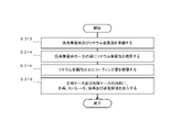
[蓄電池100の製造方法]
図2は、蓄電池100の製造方法の一例を概略的に示す。本実施形態によれば、まず、ステップ212(ステップがSと略記される場合がある。)において、例えば、シート状の負極集電体142と、負極活物質層144としてのリチウム金属箔とが準備される。次に、S214において、負極集電体142と、リチウム金属箔とを積層する。例えば、負極集電体142の少なくとも一方の面の表面に、リチウム金属箔を圧着する。
図2は、蓄電池100の製造方法の一例を概略的に示す。本実施形態によれば、まず、ステップ212(ステップがSと略記される場合がある。)において、例えば、シート状の負極集電体142と、負極活物質層144としてのリチウム金属箔とが準備される。次に、S214において、負極集電体142と、リチウム金属箔とを積層する。例えば、負極集電体142の少なくとも一方の面の表面に、リチウム金属箔を圧着する。
次に、S216において、負極集電体142に圧着されたリチウム金属箔の負極集電体142に接する面とは反対側の面の表面の少なくとも一部に、100nm以下の厚さを有するコーティング層146を積層する。コーティング層146は、例えば、物理気相蒸着法(PVD法)、化学気相蒸着法(CVD法)又は原子層堆積法(ALD法)により形成される。このとき、コーティング層146は、コーティング層146がリチウム金属箔の表面を全体的に覆うように形成される。
次に、S218において、蓄電池100が組み立てられる。具体的には、まず、正極ケース112及び負極ケース114の内部に、正極120、セパレータ130、負極140、スペーサ116及び金属バネ118が配置される。また、正極ケース112及び負極ケース114の内部に、非水電解液150が注入される。その後、正極ケース112及び負極ケース114が封入され、蓄電池100が得られる。
[別実施形態の一例]
本実施形態においては、リチウム金属箔が負極集電体142に圧着された後、リチウム金属箔の表面にコーティング層146が形成された。しかしながら、負極140の作製手順は、本実施形態に限定されない。他の実施形態によれば、リチウム金属箔の少なくとも一方の面の表面にコーティング層146が形成された後、コーティング層146の形成されたリチウム金属箔が、負極集電体142に圧着される。
本実施形態においては、リチウム金属箔が負極集電体142に圧着された後、リチウム金属箔の表面にコーティング層146が形成された。しかしながら、負極140の作製手順は、本実施形態に限定されない。他の実施形態によれば、リチウム金属箔の少なくとも一方の面の表面にコーティング層146が形成された後、コーティング層146の形成されたリチウム金属箔が、負極集電体142に圧着される。
蓄電池100をさらに具体的に説明することを目的として、下記の実施例により蓄電池100の詳細が説明される。下記の実施例においては、「対称セル」を用いて負極の性能が評価される。対称セルにおいては、材料、質量及び厚さの等しい2枚の等価な電極がセル内で対称に配置される。しかしながら、下記の実施例に対して多様な変更または改良が加えられてよく、蓄電池100は下記の実施例に限定されるものではない。
[実施例1]
まず、下記の手順により負極を作製した。負極集電体142として、厚さが10μmのCu箔を準備した。また、負極活物質層144として、厚さが20μmリチウム金属箔を準備した。次に、Cu箔の一方の面の表面にリチウム金属箔を圧着した。その後、PVD法により、リチウム金属箔の表面にAl2O3を堆積させて、コーティング層146としてのAl2O3層を形成した。Al2O3層の厚さは10nmであった。これにより、Cu集電体、Li層及びAl2O3層がこの順に積層した負極が得られた。
まず、下記の手順により負極を作製した。負極集電体142として、厚さが10μmのCu箔を準備した。また、負極活物質層144として、厚さが20μmリチウム金属箔を準備した。次に、Cu箔の一方の面の表面にリチウム金属箔を圧着した。その後、PVD法により、リチウム金属箔の表面にAl2O3を堆積させて、コーティング層146としてのAl2O3層を形成した。Al2O3層の厚さは10nmであった。これにより、Cu集電体、Li層及びAl2O3層がこの順に積層した負極が得られた。
次に、負極と同様の手順により、正極を作製した。これにより、Cu集電体、Li層及びAl2O3層がこの順に積層した正極が得られた。
また、セパレータ130として、厚さが16μmのポリエチレンを準備した。また、エチルメチルカーボネート及びフッ化エチレンカーボネートの混合溶媒と、六フッ化リン酸リチウムとを含む非水電解液を準備した。六フッ化リン酸リチウム:フッ化エチレンカーボネート:エチルメチルカーボネートは、12.6:18.0:69.4(体積%)であった。混合溶媒全体に対するフッ化エチレンカーボネートのモル%は、20モル%以上であった。上述された正極、負極、セパレータ及び非水電解液を用いて、コイン型電池を作製した。これにより、評価用対称セルが作製された。
[実施例2]
非水電解液における六フッ化リン酸リチウム:フッ化エチレンカーボネート:エチルメチルカーボネートの混合比が、12.8:22.1:65.1(体積%)である点を除いて、実施例1と同様の手順により、コイン型電池を作製した。これにより、評価用対称セルが作製された。
非水電解液における六フッ化リン酸リチウム:フッ化エチレンカーボネート:エチルメチルカーボネートの混合比が、12.8:22.1:65.1(体積%)である点を除いて、実施例1と同様の手順により、コイン型電池を作製した。これにより、評価用対称セルが作製された。
[比較例1]
まず、下記の手順により負極を作製した。負極集電体142として、厚さが10μmのCu箔を準備した。また、負極活物質層144として、厚さが20μmリチウム金属箔を準備した。これにより、Cu集電体及びLi層がこの順に積層した負極が得られた。
まず、下記の手順により負極を作製した。負極集電体142として、厚さが10μmのCu箔を準備した。また、負極活物質層144として、厚さが20μmリチウム金属箔を準備した。これにより、Cu集電体及びLi層がこの順に積層した負極が得られた。
次に、負極と同様の手順により、正極を作製した。これにより、Cu集電体及びLi層がこの順に積層した正極が得られた。また、実施例1と同様のセパレータ及び非電解液を準備した。実施例1と同様にして、コイン型電池を作製した。これにより、評価用対称セルが作製された。
[試験例1]
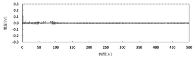
実施例1において作製された評価用対称セルを用いて、当該対称セルのサイクル特性を評価した。具体的には、定電流での充電及び放電を250サイクル繰り返し、充放電時の電圧値を記録した。1サイクル当たりの充電時間は1時間であり、1サイクル当たりの放電時間は1時間であった。充電時の条件は、温度が23[℃]であり、電流密度が1[mA/cm2]であり、電流値が0.2[mA]であった。放電時の条件は、温度が23[℃]であり、電流密度が1[mA/cm2]であり、電流値が0.2[mA]であった。
実施例1において作製された評価用対称セルを用いて、当該対称セルのサイクル特性を評価した。具体的には、定電流での充電及び放電を250サイクル繰り返し、充放電時の電圧値を記録した。1サイクル当たりの充電時間は1時間であり、1サイクル当たりの放電時間は1時間であった。充電時の条件は、温度が23[℃]であり、電流密度が1[mA/cm2]であり、電流値が0.2[mA]であった。放電時の条件は、温度が23[℃]であり、電流密度が1[mA/cm2]であり、電流値が0.2[mA]であった。
試験例1の結果を図3に示す。実施例1においては、正極及び負極として、材料、質量及び厚さの等しい2枚の等価な電極が用いられている。そのため、作動電圧は0Vであり、電極が正常な範囲においては充放電曲線も略対称な形状を有する。試験例1においては、500時間が経過した後であっても、過電圧が抑制されており、負極が安定していることがわかる。
[試験例2]
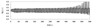
比較例1において作製された評価用対称セルを用いて、当該対称セルのサイクル特性を評価した。具体的には、定電流での充電及び放電を250サイクル繰り返し、充放電時の電圧値を記録した。1サイクル当たりの充電時間は1時間であり、1サイクル当たりの放電時間は1時間であった。充電時の条件、及び、放電時の条件は、試験例1と同様であった。
比較例1において作製された評価用対称セルを用いて、当該対称セルのサイクル特性を評価した。具体的には、定電流での充電及び放電を250サイクル繰り返し、充放電時の電圧値を記録した。1サイクル当たりの充電時間は1時間であり、1サイクル当たりの放電時間は1時間であった。充電時の条件、及び、放電時の条件は、試験例1と同様であった。
試験例2の結果を図4に示す。試験例2においては、500時間が経過した時点において、過電圧が発生していることがわかる。
[試験例3]
実施例2において作製された評価用対称セルを用いて、当該対称セルのサイクル特性を評価した。具体的には、定電流での充電及び放電を50サイクル繰り返し、充放電時の電圧値を記録した。1サイクル当たりの充電時間は1時間であり、1サイクル当たりの放電時間は1時間であった。充電時の条件、及び、放電時の条件は、試験例1と同様であった。
実施例2において作製された評価用対称セルを用いて、当該対称セルのサイクル特性を評価した。具体的には、定電流での充電及び放電を50サイクル繰り返し、充放電時の電圧値を記録した。1サイクル当たりの充電時間は1時間であり、1サイクル当たりの放電時間は1時間であった。充電時の条件、及び、放電時の条件は、試験例1と同様であった。
サイクル特性試験の結果を図5に示す。試験例3においては、100時間が経過した後であっても、過電圧が抑制されており、負極が安定していることがわかる。
以上のとおり、リチウム金属層の表面に10nmのAl2O3層を形成することで、負極の安定化が実現された。上述されたとおり、In、Mg、Ag、Si及びSnも、Alと同様に、デンドライト状のリチウムの発生及び/又は成長を抑制し得る。また、これらの金属の酸化物、窒化物、フッ化物及びリン化物は、Al2O3層と同様に、導電性又はイオン伝導性に優れたコーティング層を形成し得る。したがって、本開示によれば、負極が、一般式MxAyで表される化合物からなる層を備えることにより、リチウム二次電池の性能の低下が抑制され、電池駆動時の安定性が向上することが実証された。
以上、本発明を実施の形態を用いて説明したが、本発明の技術的範囲は上記実施の形態に記載の範囲には限定されない。上記実施の形態に、多様な変更または改良を加えることが可能であることが当業者に明らかである。その様な変更または改良を加えた形態も本発明の技術的範囲に含まれ得ることが、請求の範囲の記載から明らかである。
請求の範囲、明細書、および図面中において示した装置、システム、プログラム、および方法における動作、手順、ステップ、および段階などの各処理の実行順序は、特段「より前に」、「先立って」などと明示しておらず、また、前の処理の出力を後の処理で用いるのでない限り、任意の順序で実現しうることに留意すべきである。請求の範囲、明細書、および図面中の動作フローに関して、便宜上「まず、」、「次に、」などを用いて説明したとしても、この順で実施することが必須であることを意味するものではない。
100 蓄電池、112 正極ケース、114 負極ケース、116 スペーサ、118 金属バネ、120 正極、122 正極集電体、124 正極活物質層、130 セパレータ、140 負極、142 負極集電体、144 負極活物質層、146 コーティング層、150 非水電解液
Claims (13)
- 非水電解液を含むリチウム二次電池の負極に用いられる負極用材料であって、
リチウム金属を負極活物質として含む第1層と、
前記第1層の少なくとも一方の面に配される第2層と、
を備え、
前記第2層は、
一般式MxAy(Mは、Al、In、Mg、Ag、Si及びSnからなる群より選択される一種の元素であり、Aは、O、N、P及びFからなる群より選択される一種の元素であり、0.3<x/y<3である。)で表される化合物からなり、
100nm以下の厚さを有する、
負極用材料。 - 前記第2層は、10nm以下の厚さを有する、
請求項1に記載の負極用材料。 - Aは、O及びNからなる群より選択される一種の元素である、
請求項1又は請求項2に記載の負極用材料。 - 請求項1から請求項3までの何れか一項に記載の負極用材料と、
前記負極用材料を保持する負極集電体と、
を備える、負極。 - 前記第2層は、前記負極集電体に接して配された前記第1層を全体的に覆うように配される、
請求項4に記載の負極。 - 前記第2層は、前記第2層の一部が前記負極集電体に接するように配される、
請求項4又は請求項5に記載の負極。 - 請求項4から請求項6までの何れか一項に記載の負極と、
正極と、
非水電解液と、
を備える、リチウム二次電池。 - 前記非水電解液は、フッ素原子を有する環状カーボネートを含む、
請求項7に記載のリチウム二次電池。 - 前記非水電解液の全体に対する、前記フッ素原子を有する環状カーボネートの割合は、20モル%以上80モル%以下である、
請求項8に記載のリチウム二次電池。 - 前記フッ素原子を有する環状カーボネートは、フルオロエチレンカーボネート(FEC)、又は、ジフルオロエチレンカーボネート(DFEC)を含む、
請求項8又は請求項9に記載のリチウム二次電池。 - 前記負極は、
前記リチウム二次電池の充放電が少なくとも1回実施された後、
リチウムと、前記第2層に含まれるMで表される元素との合金を含む、
請求項7から請求項10までの何れか一項に記載のリチウム二次電池。 - 前記第2層は、Aで表される元素として窒素を含み
前記負極は、前記リチウム二次電池の充放電が少なくとも1回実施された後、窒化リチウムを含む、
請求項11に記載のリチウム二次電池。 - 非水電解液を含むリチウム二次電池に用いられる負極を製造する方法であって、
リチウム金属を負極活物質として含む第1層を準備する段階と、
前記第1層の少なくとも一方の面に第2層を形成する段階と、
を有し、
前記第2層は、
一般式MxAy(Mは、Al、In、Mg、Ag、Si及びSnからなる群より選択される一種の元素であり、Aは、O、N、P及びFからなる群より選択される一種の元素であり、0.3<x/y<3である。)で表される化合物からなり、
100nm以下の厚さを有する、
方法。
Priority Applications (2)
| Application Number | Priority Date | Filing Date | Title |
|---|---|---|---|
| EP22767251.6A EP4235852A4 (en) | 2021-03-12 | 2022-03-10 | NEGATIVE ELECTRODE MATERIAL, NEGATIVE ELECTRODE, LITHIUM SECONDARY BATTERY AND METHOD FOR PRODUCING THE NEGATIVE ELECTRODE MATERIAL |
| US18/191,888 US20230231117A1 (en) | 2021-03-12 | 2023-03-29 | Negative electrode material, negative electrode, lithium secondary battery, and manufacturing method for negative electrode material |
Applications Claiming Priority (2)
| Application Number | Priority Date | Filing Date | Title |
|---|---|---|---|
| JP2021040663A JP2022140029A (ja) | 2021-03-12 | 2021-03-12 | 負極用材料、負極、リチウム二次電池、及び、負極用材料の製造方法 |
| JP2021-040663 | 2021-03-12 |
Related Child Applications (1)
| Application Number | Title | Priority Date | Filing Date |
|---|---|---|---|
| US18/191,888 Continuation US20230231117A1 (en) | 2021-03-12 | 2023-03-29 | Negative electrode material, negative electrode, lithium secondary battery, and manufacturing method for negative electrode material |
Publications (1)
| Publication Number | Publication Date |
|---|---|
| WO2022191297A1 true WO2022191297A1 (ja) | 2022-09-15 |
Family
ID=83228119
Family Applications (1)
| Application Number | Title | Priority Date | Filing Date |
|---|---|---|---|
| PCT/JP2022/010722 Ceased WO2022191297A1 (ja) | 2021-03-12 | 2022-03-10 | 負極用材料、負極、リチウム二次電池、及び、負極用材料の製造方法 |
Country Status (4)
| Country | Link |
|---|---|
| US (1) | US20230231117A1 (ja) |
| EP (1) | EP4235852A4 (ja) |
| JP (1) | JP2022140029A (ja) |
| WO (1) | WO2022191297A1 (ja) |
Families Citing this family (2)
| Publication number | Priority date | Publication date | Assignee | Title |
|---|---|---|---|---|
| US20230197928A1 (en) * | 2021-12-22 | 2023-06-22 | GM Global Technology Operations LLC | Battery electrode |
| JP2025067532A (ja) * | 2023-10-13 | 2025-04-24 | トヨタ自動車株式会社 | 全固体電池 |
Citations (13)
| Publication number | Priority date | Publication date | Assignee | Title |
|---|---|---|---|---|
| US5314765A (en) | 1993-10-14 | 1994-05-24 | Martin Marietta Energy Systems, Inc. | Protective lithium ion conducting ceramic coating for lithium metal anodes and associate method |
| JP2005063731A (ja) * | 2003-08-08 | 2005-03-10 | Japan Storage Battery Co Ltd | 非水電解質二次電池およびその製造方法 |
| JP2009502011A (ja) * | 2005-07-15 | 2009-01-22 | シンベット・コーポレイション | 軟質および硬質電解質層付き薄膜電池および方法 |
| JP2017528893A (ja) * | 2014-09-29 | 2017-09-28 | エルジー・ケム・リミテッド | アノード、これを含むリチウム二次電池、前記リチウム二次電池を含む電池モジュール、およびアノードの製造方法 |
| JP2017531279A (ja) * | 2014-09-05 | 2017-10-19 | エルジー・ケム・リミテッド | リチウム電極、これを含むリチウム二次電池、前記リチウム二次電池を含む電池モジュールおよびリチウム電極の製造方法 |
| JP2018004336A (ja) * | 2016-06-29 | 2018-01-11 | 日本電気株式会社 | 検査装置、検査方法および検査プログラム |
| JP2018502416A (ja) * | 2014-10-28 | 2018-01-25 | ユニバーシティー オブ メリーランド,カレッジ パーク | 固体電池の界面層及びその製造方法 |
| JP2019153539A (ja) * | 2018-03-06 | 2019-09-12 | 三洋電機株式会社 | 非水電解質二次電池 |
| US10461372B2 (en) | 2015-05-20 | 2019-10-29 | Sion Power Corporation | Protective layers for electrochemical cells |
| JP2020030937A (ja) * | 2018-08-22 | 2020-02-27 | 株式会社豊田自動織機 | 電解液 |
| WO2020072524A1 (en) * | 2018-10-02 | 2020-04-09 | Quantumscape Corporation | Methods of making and using an electrochemical cell comprising an interlayer |
| WO2020179669A1 (ja) * | 2019-03-01 | 2020-09-10 | 積水化学工業株式会社 | リチウムイオン二次電池用電極、及びリチウムイオン二次電池 |
| US10833360B2 (en) | 2016-03-11 | 2020-11-10 | Northwestern University | Protective anode coatings for high energy batteries |
Family Cites Families (12)
| Publication number | Priority date | Publication date | Assignee | Title |
|---|---|---|---|---|
| FR2873854A1 (fr) * | 2004-07-30 | 2006-02-03 | Commissariat Energie Atomique | Procede de fabrication d'une electrode lithiee, electrode lithiee susceptible d'etre obtenue par ce procede et ses utilisations |
| JP5515308B2 (ja) * | 2009-02-03 | 2014-06-11 | ソニー株式会社 | 薄膜固体リチウムイオン二次電池及びその製造方法 |
| KR102270864B1 (ko) * | 2017-04-19 | 2021-07-01 | 주식회사 엘지에너지솔루션 | 리튬 이차전지용 음극, 이를 포함하는 리튬 이차전지, 및 이의 제조 방법 |
| US11322736B2 (en) * | 2017-06-08 | 2022-05-03 | Lg Energy Solution, Ltd. | Negative electrode, secondary battery including the same, and method of preparing the negative electrode |
| KR102120278B1 (ko) * | 2017-11-24 | 2020-06-08 | 주식회사 엘지화학 | 리튬 전극 및 그를 포함하는 리튬 이차전지 |
| KR102601605B1 (ko) * | 2017-12-27 | 2023-11-14 | 삼성전자주식회사 | 음극, 이를 포함하는 리튬전지 및 음극 제조방법 |
| JP2019175568A (ja) * | 2018-03-27 | 2019-10-10 | 本田技研工業株式会社 | リチウムイオン二次電池 |
| JP2019200977A (ja) * | 2018-05-18 | 2019-11-21 | 株式会社豊田自動織機 | 電解液 |
| CN109378491A (zh) * | 2018-09-27 | 2019-02-22 | 山东大学 | 一种锂空气电池及其制备方法 |
| JP2020191247A (ja) * | 2019-05-22 | 2020-11-26 | パナソニックIpマネジメント株式会社 | 非水電解質二次電池 |
| JP2020198297A (ja) * | 2019-05-30 | 2020-12-10 | パナソニックIpマネジメント株式会社 | 二次電池 |
| CN112103512A (zh) * | 2020-10-09 | 2020-12-18 | 中国科学院物理研究所 | 一种负极集流体、其制备方法与应用 |
-
2021
- 2021-03-12 JP JP2021040663A patent/JP2022140029A/ja active Pending
-
2022
- 2022-03-10 EP EP22767251.6A patent/EP4235852A4/en active Pending
- 2022-03-10 WO PCT/JP2022/010722 patent/WO2022191297A1/ja not_active Ceased
-
2023
- 2023-03-29 US US18/191,888 patent/US20230231117A1/en active Pending
Patent Citations (13)
| Publication number | Priority date | Publication date | Assignee | Title |
|---|---|---|---|---|
| US5314765A (en) | 1993-10-14 | 1994-05-24 | Martin Marietta Energy Systems, Inc. | Protective lithium ion conducting ceramic coating for lithium metal anodes and associate method |
| JP2005063731A (ja) * | 2003-08-08 | 2005-03-10 | Japan Storage Battery Co Ltd | 非水電解質二次電池およびその製造方法 |
| JP2009502011A (ja) * | 2005-07-15 | 2009-01-22 | シンベット・コーポレイション | 軟質および硬質電解質層付き薄膜電池および方法 |
| JP2017531279A (ja) * | 2014-09-05 | 2017-10-19 | エルジー・ケム・リミテッド | リチウム電極、これを含むリチウム二次電池、前記リチウム二次電池を含む電池モジュールおよびリチウム電極の製造方法 |
| JP2017528893A (ja) * | 2014-09-29 | 2017-09-28 | エルジー・ケム・リミテッド | アノード、これを含むリチウム二次電池、前記リチウム二次電池を含む電池モジュール、およびアノードの製造方法 |
| JP2018502416A (ja) * | 2014-10-28 | 2018-01-25 | ユニバーシティー オブ メリーランド,カレッジ パーク | 固体電池の界面層及びその製造方法 |
| US10461372B2 (en) | 2015-05-20 | 2019-10-29 | Sion Power Corporation | Protective layers for electrochemical cells |
| US10833360B2 (en) | 2016-03-11 | 2020-11-10 | Northwestern University | Protective anode coatings for high energy batteries |
| JP2018004336A (ja) * | 2016-06-29 | 2018-01-11 | 日本電気株式会社 | 検査装置、検査方法および検査プログラム |
| JP2019153539A (ja) * | 2018-03-06 | 2019-09-12 | 三洋電機株式会社 | 非水電解質二次電池 |
| JP2020030937A (ja) * | 2018-08-22 | 2020-02-27 | 株式会社豊田自動織機 | 電解液 |
| WO2020072524A1 (en) * | 2018-10-02 | 2020-04-09 | Quantumscape Corporation | Methods of making and using an electrochemical cell comprising an interlayer |
| WO2020179669A1 (ja) * | 2019-03-01 | 2020-09-10 | 積水化学工業株式会社 | リチウムイオン二次電池用電極、及びリチウムイオン二次電池 |
Non-Patent Citations (1)
| Title |
|---|
| See also references of EP4235852A4 |
Also Published As
| Publication number | Publication date |
|---|---|
| JP2022140029A (ja) | 2022-09-26 |
| US20230231117A1 (en) | 2023-07-20 |
| EP4235852A4 (en) | 2024-11-20 |
| EP4235852A1 (en) | 2023-08-30 |
Similar Documents
| Publication | Publication Date | Title |
|---|---|---|
| US10673046B2 (en) | Separator for lithium metal based batteries | |
| US9401529B2 (en) | Nonaqueous electrolytic solution and battery including a heteropolyacid and/or a heteropolyacid compound | |
| US20090017386A1 (en) | Non-Aqueous Electrolytic Solutions And Electrochemical Cells Comprising The Same | |
| US20080138713A1 (en) | Rechargeable lithium battery | |
| JP6279233B2 (ja) | リチウム二次電池 | |
| CN109155426B (zh) | 锂离子二次电池 | |
| WO2018179817A1 (ja) | 非水電解質二次電池用負極及び非水電解質二次電池 | |
| KR20090020487A (ko) | 비수 전해액 2차 전지 | |
| JP2011096638A (ja) | 二次電池 | |
| JP2008135273A (ja) | 電解液および電池 | |
| CN117121257A (zh) | 锂二次电池用非水性电解质溶液及包含其的锂二次电池 | |
| JP6656370B2 (ja) | リチウムイオン二次電池および組電池 | |
| JP2012084426A (ja) | 非水電解質二次電池 | |
| JP2008262900A (ja) | 非水電解質およびこれを用いた非水電解質電池 | |
| US20230231117A1 (en) | Negative electrode material, negative electrode, lithium secondary battery, and manufacturing method for negative electrode material | |
| JP2014007010A (ja) | リチウム二次電池 | |
| US11600814B2 (en) | Nickel-containing positive electrode slurries having reduced or eliminated gelation and high-energy-density positive electrodes for electrochemical cells | |
| KR100834053B1 (ko) | 양극, 이를 포함하는 리튬 이차 전지, 및 이를 포함하는 하이브리드 커패시터 | |
| JP7573925B1 (ja) | リチウム2次電池及びリチウム2次電池の製造方法 | |
| JP4582684B2 (ja) | 非水二次電池 | |
| JP2003168427A (ja) | 非水電解質電池 | |
| KR102619182B1 (ko) | 리튬 이차전지용 비수전해액 및 이를 포함하는 리튬 이차전지 | |
| JP4078864B2 (ja) | 二次電池用負極および二次電池 | |
| US9466837B1 (en) | Battery having negative electrode including amorphous carbon | |
| JP5426809B2 (ja) | 二次電池、二次電池を用いた電子機器及び輸送用機器 |
Legal Events
| Date | Code | Title | Description |
|---|---|---|---|
| 121 | Ep: the epo has been informed by wipo that ep was designated in this application |
Ref document number: 22767251 Country of ref document: EP Kind code of ref document: A1 |
|
| ENP | Entry into the national phase |
Ref document number: 2022767251 Country of ref document: EP Effective date: 20230523 |
|
| NENP | Non-entry into the national phase |
Ref country code: DE |