WO2022196242A1 - 遠隔操縦装置 - Google Patents
遠隔操縦装置 Download PDFInfo
- Publication number
- WO2022196242A1 WO2022196242A1 PCT/JP2022/006559 JP2022006559W WO2022196242A1 WO 2022196242 A1 WO2022196242 A1 WO 2022196242A1 JP 2022006559 W JP2022006559 W JP 2022006559W WO 2022196242 A1 WO2022196242 A1 WO 2022196242A1
- Authority
- WO
- WIPO (PCT)
- Prior art keywords
- display
- communication
- control device
- remote control
- predicted trajectory
- Prior art date
- Legal status (The legal status is an assumption and is not a legal conclusion. Google has not performed a legal analysis and makes no representation as to the accuracy of the status listed.)
- Ceased
Links
Images





Classifications
-
- E—FIXED CONSTRUCTIONS
- E02—HYDRAULIC ENGINEERING; FOUNDATIONS; SOIL SHIFTING
- E02F—DREDGING; SOIL-SHIFTING
- E02F9/00—Component parts of dredgers or soil-shifting machines, not restricted to one of the kinds covered by groups E02F3/00 - E02F7/00
- E02F9/20—Drives; Control devices
- E02F9/2025—Particular purposes of control systems not otherwise provided for
- E02F9/205—Remotely operated machines, e.g. unmanned vehicles
-
- E—FIXED CONSTRUCTIONS
- E02—HYDRAULIC ENGINEERING; FOUNDATIONS; SOIL SHIFTING
- E02F—DREDGING; SOIL-SHIFTING
- E02F9/00—Component parts of dredgers or soil-shifting machines, not restricted to one of the kinds covered by groups E02F3/00 - E02F7/00
- E02F9/20—Drives; Control devices
- E02F9/22—Hydraulic or pneumatic drives
- E02F9/2221—Control of flow rate; Load sensing arrangements
- E02F9/2225—Control of flow rate; Load sensing arrangements using pressure-compensating valves
- E02F9/2228—Control of flow rate; Load sensing arrangements using pressure-compensating valves including an electronic controller
-
- E—FIXED CONSTRUCTIONS
- E02—HYDRAULIC ENGINEERING; FOUNDATIONS; SOIL SHIFTING
- E02F—DREDGING; SOIL-SHIFTING
- E02F9/00—Component parts of dredgers or soil-shifting machines, not restricted to one of the kinds covered by groups E02F3/00 - E02F7/00
- E02F9/20—Drives; Control devices
- E02F9/22—Hydraulic or pneumatic drives
- E02F9/2221—Control of flow rate; Load sensing arrangements
- E02F9/2232—Control of flow rate; Load sensing arrangements using one or more variable displacement pumps
- E02F9/2235—Control of flow rate; Load sensing arrangements using one or more variable displacement pumps including an electronic controller
-
- E—FIXED CONSTRUCTIONS
- E02—HYDRAULIC ENGINEERING; FOUNDATIONS; SOIL SHIFTING
- E02F—DREDGING; SOIL-SHIFTING
- E02F9/00—Component parts of dredgers or soil-shifting machines, not restricted to one of the kinds covered by groups E02F3/00 - E02F7/00
- E02F9/20—Drives; Control devices
- E02F9/22—Hydraulic or pneumatic drives
- E02F9/2278—Hydraulic circuits
- E02F9/2285—Pilot-operated systems
-
- E—FIXED CONSTRUCTIONS
- E02—HYDRAULIC ENGINEERING; FOUNDATIONS; SOIL SHIFTING
- E02F—DREDGING; SOIL-SHIFTING
- E02F9/00—Component parts of dredgers or soil-shifting machines, not restricted to one of the kinds covered by groups E02F3/00 - E02F7/00
- E02F9/20—Drives; Control devices
- E02F9/22—Hydraulic or pneumatic drives
- E02F9/2278—Hydraulic circuits
- E02F9/2292—Systems with two or more pumps
-
- E—FIXED CONSTRUCTIONS
- E02—HYDRAULIC ENGINEERING; FOUNDATIONS; SOIL SHIFTING
- E02F—DREDGING; SOIL-SHIFTING
- E02F9/00—Component parts of dredgers or soil-shifting machines, not restricted to one of the kinds covered by groups E02F3/00 - E02F7/00
- E02F9/26—Indicating devices
-
- E—FIXED CONSTRUCTIONS
- E02—HYDRAULIC ENGINEERING; FOUNDATIONS; SOIL SHIFTING
- E02F—DREDGING; SOIL-SHIFTING
- E02F9/00—Component parts of dredgers or soil-shifting machines, not restricted to one of the kinds covered by groups E02F3/00 - E02F7/00
- E02F9/26—Indicating devices
- E02F9/261—Surveying the work-site to be treated
-
- E—FIXED CONSTRUCTIONS
- E02—HYDRAULIC ENGINEERING; FOUNDATIONS; SOIL SHIFTING
- E02F—DREDGING; SOIL-SHIFTING
- E02F9/00—Component parts of dredgers or soil-shifting machines, not restricted to one of the kinds covered by groups E02F3/00 - E02F7/00
- E02F9/26—Indicating devices
- E02F9/264—Sensors and their calibration for indicating the position of the work tool
-
- E—FIXED CONSTRUCTIONS
- E02—HYDRAULIC ENGINEERING; FOUNDATIONS; SOIL SHIFTING
- E02F—DREDGING; SOIL-SHIFTING
- E02F9/00—Component parts of dredgers or soil-shifting machines, not restricted to one of the kinds covered by groups E02F3/00 - E02F7/00
- E02F9/26—Indicating devices
- E02F9/267—Diagnosing or detecting failure of vehicles
-
- F—MECHANICAL ENGINEERING; LIGHTING; HEATING; WEAPONS; BLASTING
- F02—COMBUSTION ENGINES; HOT-GAS OR COMBUSTION-PRODUCT ENGINE PLANTS
- F02D—CONTROLLING COMBUSTION ENGINES
- F02D29/00—Controlling engines, such controlling being peculiar to the devices driven thereby, the devices being other than parts or accessories essential to engine operation, e.g. controlling of engines by signals external thereto
-
- F—MECHANICAL ENGINEERING; LIGHTING; HEATING; WEAPONS; BLASTING
- F02—COMBUSTION ENGINES; HOT-GAS OR COMBUSTION-PRODUCT ENGINE PLANTS
- F02D—CONTROLLING COMBUSTION ENGINES
- F02D29/00—Controlling engines, such controlling being peculiar to the devices driven thereby, the devices being other than parts or accessories essential to engine operation, e.g. controlling of engines by signals external thereto
- F02D29/02—Controlling engines, such controlling being peculiar to the devices driven thereby, the devices being other than parts or accessories essential to engine operation, e.g. controlling of engines by signals external thereto peculiar to engines driving vehicles; peculiar to engines driving variable pitch propellers
-
- G—PHYSICS
- G05—CONTROLLING; REGULATING
- G05D—SYSTEMS FOR CONTROLLING OR REGULATING NON-ELECTRIC VARIABLES
- G05D1/00—Control of position, course, altitude or attitude of land, water, air or space vehicles, e.g. using automatic pilots
- G05D1/0011—Control of position, course, altitude or attitude of land, water, air or space vehicles, e.g. using automatic pilots associated with a remote control arrangement
- G05D1/0038—Control of position, course, altitude or attitude of land, water, air or space vehicles, e.g. using automatic pilots associated with a remote control arrangement by providing the operator with simple or augmented images from one or more cameras located onboard the vehicle, e.g. tele-operation
-
- G—PHYSICS
- G05—CONTROLLING; REGULATING
- G05D—SYSTEMS FOR CONTROLLING OR REGULATING NON-ELECTRIC VARIABLES
- G05D1/00—Control of position, course, altitude or attitude of land, water, air or space vehicles, e.g. using automatic pilots
- G05D1/20—Control system inputs
- G05D1/22—Command input arrangements
- G05D1/221—Remote-control arrangements
- G05D1/222—Remote-control arrangements operated by humans
- G05D1/224—Output arrangements on the remote controller, e.g. displays, haptics or speakers
- G05D1/2244—Optic
- G05D1/2247—Optic providing the operator with simple or augmented images from one or more cameras
-
- G—PHYSICS
- G05—CONTROLLING; REGULATING
- G05D—SYSTEMS FOR CONTROLLING OR REGULATING NON-ELECTRIC VARIABLES
- G05D1/00—Control of position, course, altitude or attitude of land, water, air or space vehicles, e.g. using automatic pilots
- G05D1/20—Control system inputs
- G05D1/22—Command input arrangements
- G05D1/221—Remote-control arrangements
- G05D1/226—Communication links with the remote-control arrangements
-
- H—ELECTRICITY
- H04—ELECTRIC COMMUNICATION TECHNIQUE
- H04N—PICTORIAL COMMUNICATION, e.g. TELEVISION
- H04N7/00—Television systems
- H04N7/18—Closed-circuit television [CCTV] systems, i.e. systems in which the video signal is not broadcast
-
- H—ELECTRICITY
- H04—ELECTRIC COMMUNICATION TECHNIQUE
- H04N—PICTORIAL COMMUNICATION, e.g. TELEVISION
- H04N7/00—Television systems
- H04N7/18—Closed-circuit television [CCTV] systems, i.e. systems in which the video signal is not broadcast
- H04N7/181—Closed-circuit television [CCTV] systems, i.e. systems in which the video signal is not broadcast for receiving images from a plurality of remote sources
-
- B—PERFORMING OPERATIONS; TRANSPORTING
- B60—VEHICLES IN GENERAL
- B60Y—INDEXING SCHEME RELATING TO ASPECTS CROSS-CUTTING VEHICLE TECHNOLOGY
- B60Y2200/00—Type of vehicle
- B60Y2200/40—Special vehicles
- B60Y2200/41—Construction vehicles, e.g. graders, excavators
- B60Y2200/412—Excavators
-
- G—PHYSICS
- G05—CONTROLLING; REGULATING
- G05D—SYSTEMS FOR CONTROLLING OR REGULATING NON-ELECTRIC VARIABLES
- G05D2105/00—Specific applications of the controlled vehicles
- G05D2105/05—Specific applications of the controlled vehicles for soil shifting, building, civil engineering or mining, e.g. excavators
-
- G—PHYSICS
- G05—CONTROLLING; REGULATING
- G05D—SYSTEMS FOR CONTROLLING OR REGULATING NON-ELECTRIC VARIABLES
- G05D2109/00—Types of controlled vehicles
- G05D2109/10—Land vehicles
Definitions
- the present invention relates to a remote control device.
- a working machine is equipped with an image acquisition device (camera) in order to provide visual information to a remote operator when operating the working machine remotely.
- the image of the work site acquired by the image acquisition device (camera) is displayed on the display device provided to the remote control device of the remote operator.
- the operator operates the working machine by the remote control device while confirming the image displayed on the display device.
- Patent Document 1 a work site is imaged by an image acquisition device of a work machine, a virtual viewpoint image of the work machine viewed from a virtual viewpoint is generated, and a real image and a virtual viewpoint are captured by the image acquisition device of the work machine.
- a technique for displaying images at different positions on the same screen of a display device is disclosed.
- the present invention has been created with the object of solving the above problems, and is a remote controller that enables efficient and safe remote control of a work machine operated from a remote location even when there is a communication delay.
- the object is to provide a steering device.
- the remote control device of the present invention is a remote control device comprising a control device for transmitting an operation signal to a work machine to control the work machine from a remote location, wherein the control device is a communication control unit for receiving a camera image of a work site taken by a camera and vehicle body information of the work machine; and a predicted trajectory for calculating a predicted trajectory of the work machine from the vehicle body information and displaying it as an image on a display device.
- a predicted trajectory calculation unit that outputs data
- a display control unit that causes the display device to display the camera image and the predicted trajectory image on the same screen.
- the driver can recognize the current status of the vehicle by displaying the video of the predicted trajectory. Furthermore, by superimposing a pseudo camera image (a (pseudo) predicted image of the working machine as seen from the camera generated based on the predicted trajectory), when there is a delay in the communication line, the actual camera image and the Since the difference appears, it is possible to visually present the video delay to the operator. Therefore, even if there is a communication delay, the work machine to be operated from a remote location can be remotely operated efficiently and safely.
- a pseudo camera image a (pseudo) predicted image of the working machine as seen from the camera generated based on the predicted trajectory
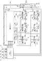
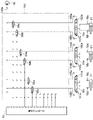
- FIG. 2 is a diagram showing a controller of a hydraulic excavator (working machine) together with a hydraulic drive; Detailed view of the solenoid valve unit.
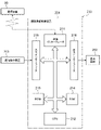
- FIG. 2 is a hardware configuration diagram of a remote control device of the remote control device of FIG. 1;
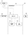
- FIG. 2 is a functional block diagram of the remote control device of the remote control device of the first embodiment shown in FIG. 1;
- 4 is a calculation processing flowchart of a predicted trajectory calculation unit according to the first embodiment;
- 4 is a control processing flowchart of a display control unit according to the first embodiment;
- 4 is a control processing flowchart of a communication control unit according to the first embodiment;
- FIG. 5 is a functional block diagram of a remote control device for a remote control device according to a second embodiment;
- FIG. 10 is an operation processing flowchart of a communication status determination unit according to the second embodiment;
- FIG. 10 is a flowchart of control processing of a communication status transmission unit according to the second embodiment;
- FIG. FIG. 10 is a control processing flowchart of a communication control unit according to the second embodiment;
- FIG. 4 is a diagram showing a display example (images displayed at different positions without being superimposed) on a display screen of a display device;
- a hydraulic excavator provided with a bucket 8 as a working tool at the tip of the working device as shown in FIG. 1 is exemplified as a working machine to be remotely controlled.
- the present invention can be applied to working machines other than hydraulic excavators as long as they have a multi-joint working device configured by connecting a plurality of link members (attachments, arms, booms, etc.).
- FIG. 1 is a diagram showing an example of a remote control system 100 for a work machine 1 according to the first embodiment of the invention.
- the remote control system 100 remotely controls the work machine 1 .
- the work machine 1 is assumed to be a hydraulic excavator.
- FIG. 2 is a diagram showing the controller of the hydraulic excavator (work machine) 1 according to the first embodiment of the present invention together with the hydraulic drive system, and
- FIG. 3 is a detailed diagram of the solenoid valve unit 160 in FIG. .
- a hydraulic excavator 1 is composed of a work front 2, which is a multi-joint work device, and a traveling body 3.
- the traveling body 3 is mounted on a lower traveling portion 3a that travels by left and right traveling hydraulic motors 4a and 4b (a right traveling hydraulic motor 4a and a left traveling hydraulic motor 4b), and is mounted on the lower traveling portion 3a. and a swiveling upper swivel portion 3b.
- the work front 2 is configured by connecting a plurality of driven members (boom 6, arm 7, and bucket 8) that rotate in the vertical direction.
- the base end of the boom 6 is rotatably supported via a boom pin in the front part of the upper turning part 3b.
- An arm 7 is rotatably connected to the tip of the boom 6 via an arm pin
- a bucket 8 is rotatably connected to the tip of the arm 7 via a bucket pin.
- the boom 6 is driven by a boom cylinder 61
- the arm 7 is driven by an arm cylinder 71
- the bucket 8 is driven by a bucket cylinder 81 .
- a boom angle sensor 62 is attached to the boom pin
- an arm angle sensor 72 is attached to the arm pin
- a bucket angle sensor 82 is attached to the bucket link 9.
- a vehicle body tilt angle sensor 31 is attached to detect the tilt angle of the upper turning portion 3b with respect to a reference plane (for example, a horizontal plane).
- the angle sensors 62, 72, and 82 can be replaced with angle sensors for a reference plane (for example, a horizontal plane).
- a turning angle sensor 32 is attached to the center axis of turning so that the relative angle between the upper turning portion 3b and the lower traveling portion 3a can be measured.
- An operation device 10 for operating the hydraulic excavator 1 is installed in an operator's cab 12 provided in the upper revolving portion 3b.
- the operation device 10 includes an operation right lever 10a for operating a boom cylinder 61 (boom 6) and a bucket cylinder 81 (bucket 8), an arm cylinder 71 (arm 7) and a swing hydraulic motor 5 (upper swing section 3b).
- the right operation lever 10a, the left operation lever 10b, the right travel lever 10c, and the left travel lever 10d may be collectively referred to as the operation device 10 below.
- An engine 11 which is a prime mover mounted on the upper swing section 3b, drives hydraulic pumps 20a and 20b and a pilot pump 30, as shown in FIG.
- the hydraulic pumps 20a and 20b are variable displacement pumps whose displacements are controlled by regulators 20aa and 20ba, and the pilot pump 30 is a fixed displacement pump. Hydraulic pump 20 and pilot pump 30 suck hydraulic oil from tank 170 .
- a control signal output from a controller 40 which is a control device, is input to regulators 20aa and 20ba.
- the detailed configuration of the regulators 20aa and 20ba is omitted, the discharge flow rates of the hydraulic pumps 20a and 20b are controlled according to the control signal.
- a pump line 143 a which is a discharge pipe of the pilot pump 30 , passes through the lock valve 39 and is connected to each electromagnetic proportional valve in the electromagnetic valve unit 160 .
- the lock valve 39 is an electromagnetic switching valve in this example, and its electromagnetic drive portion is electrically connected to the position detector of the gate lock lever arranged in the operator's cab 12 (FIG. 1). The position of the gate lock lever is detected by a position detector, and a signal corresponding to the position of the gate lock lever is input to the lock valve 39 from the position detector.
- the lock valve 39 is closed to block the pump line 143a, and when it is at the unlocked position, the lock valve 39 is opened to open the pump line 143a.
- the operation device 10 (10a, 10b, 10c, 10d) is of an electric lever type, and generates an electric signal corresponding to the amount and direction of operation by the operator.
- the electric signal generated in this way is input to the control controller 40, and controls to drive the electromagnetic proportional valves 54 to 59 (see FIG. 3, 57 to 59 are not shown) according to the operation input to the operating device 10.
- Controller 40 outputs an electrical signal to solenoid valve unit 160 .
- the electrical signals are input to the hydraulic drive units 150a-155b via the pilot lines 144a-149b.
- the pressure oil discharged from the hydraulic pump 20 flows through flow control valves 15a, 15b, 15c, 15d, 15e, and 15f (see FIG. 2 or 3, 15d, 15e, and 15f are not shown in FIG. 3) to the boom cylinder 61, the arm cylinder 71, the bucket cylinder 81, the turning hydraulic motor 5, the traveling right hydraulic motor 4a, and the traveling left hydraulic motor 4b, which are actuators. .
- the boom cylinder 61, the arm cylinder 71, and the bucket cylinder 81 expand and contract by the supplied pressure oil, so that the boom 6, the arm 7, and the bucket 8 rotate, and the position and attitude of the bucket 8 change.
- the hydraulic hydraulic motor 5 is rotated by the supplied pressure oil, so that the upper turning portion 3b turns with respect to the lower traveling portion 3a. Then, the right travel hydraulic motor 4a and the left travel hydraulic motor 4b are rotated by the supplied pressure oil, so that the lower travel portion 3a travels.
- the boom cylinder 61, arm cylinder 71, and bucket cylinder 81 are provided with load detection devices 16a to 16f so that the cylinder pressure can be detected.
- the load detection device 16 is a pressure sensor that detects the bottom side pressure and the rod side pressure of each of the boom cylinder 61, the arm cylinder 71, and the bucket cylinder 81, and outputs them to the controller 40 as electric signals. do.
- an in-vehicle camera 91 as a video acquisition device is mounted on the upper turning portion 3b.
- the vehicle-mounted camera 91 captures a camera image ( work site video).
- a camera as a video acquisition device for capturing an image of the work site is mounted on (the upper revolving portion 3b of) the hydraulic excavator 1.
- a video (worksite video) may be acquired.
- a communication device 90 is mounted on the upper turning portion 3b.
- the communication device 90 communicably connects the hydraulic excavator 1 and the remote control device 200 via a network.
- the remote control device 200 is installed at a remote location away from the work site in order to remotely control (remotely control) the hydraulic excavator 1 .
- the communication device 90 transmits the camera image from the vehicle-mounted camera 91 and the vehicle body information from each sensor (the angle sensors 62, 72, 82, 32 and the load detection devices 16a to 16f) to the remote control device 200. It receives a control signal (including an operation signal for the operation device 10 of the hydraulic excavator 1 ) from 200 and transmits it to the operation device 10 .
- the remote control device 200 includes a remote control device (control device) 201 configured by an electronic device having communication and processing functions with the hydraulic excavator 1, a display device 202 for displaying images, and a boom cylinder 61 (boom 6). and an operation right lever 203a for operating the bucket cylinder 81 (bucket 8), an operation left lever 203b for operating the arm cylinder 71 (arm 7) and the turning hydraulic motor 5 (upper turning portion 3b), and a traveling right It comprises a right travel lever 203c for operating the hydraulic motor 4a (lower travel portion 3a), a left travel lever 203d for operating the left travel hydraulic motor 4b (lower travel portion 3a), and an operator seat 204.
- a remote control device control device
- control device configured by an electronic device having communication and processing functions with the hydraulic excavator 1, a display device 202 for displaying images, and a boom cylinder 61 (boom 6).
- an operation right lever 203a for operating the bucket cylinder 81 (bucket 8), an
- the remote operation device 203 inputs an operation signal (for example, an electric signal corresponding to the operator's operation amount and operation direction) to the remote operation control device 201, and the remote operation control device 201 is mounted on the hydraulic excavator 1 via a network.
- the hydraulic excavator 1 is remotely controlled by transmitting a control signal (including an operation signal of the operating device 10 of the hydraulic excavator 1 ) to the communication device 90 .
- the display device 202 displays a superimposed image from the remote control device 201 to provide visual information to the remote control operator (described later).
- the proportional solenoid valves 54a to 59b have the smallest degree of opening when not energized, and the degree of opening increases as the current, which is the control signal from the controller 40, increases.
- the opening degree of each of the electromagnetic proportional valves 54a to 59b corresponds to the control signal from the controller 40.
- FIG. 4 is a hardware configuration diagram of the remote control device 201 of the remote control device 200 according to this embodiment.
- the remote control device 201 includes a communication interface 211, a central processing unit (CPU) 212 as a processor, a read only memory (ROM) 213 and a random access memory (RAM) 214 as storage devices, and an input interface. 215 and an output interface 216 .
- CPU central processing unit
- ROM read only memory
- RAM random access memory
- the communication interface 211 transmits and receives signals to and from the communication device 90 mounted on the hydraulic excavator 1 .
- An in-vehicle camera image of the hydraulic excavator 1 and vehicle body information are received from the communication device 90 and input to the CPU 212 . Also, it transmits a control signal from the remote control device 203 to the communication device 90 .
- the CPU 212 performs predetermined arithmetic processing on signals received from the communication interface 211 , the ROM 213 and the RAM 214 based on the control program stored in the ROM 213 .
- the ROM 213 is a recording medium that stores a control program for executing control contents including processing related to flowcharts to be described later, various information necessary for executing the flowcharts, and the like.
- the input interface 215 receives control signals from the remote control device 203 as input signals and outputs them to the communication interface 211 .
- the output interface 216 creates an output signal according to the calculation result of the CPU 212 and displays the signal on the screen of the display device 202 .
- FIG. 5 is a functional block diagram of the remote control device 201 of the remote control device 200 according to this embodiment.
- the remote control device 201 includes a predicted trajectory calculation unit 220, a display control unit 221, and a communication control unit 222.
- the predicted trajectory calculation unit 220 calculates the predicted trajectory of the hydraulic excavator 1 from the vehicle body information input from the communication interface 211 (Fig. 4) and outputs the predicted trajectory data. For example, a video signal (corresponding to predicted trajectory data) for drawing the posture of the hydraulic excavator 1 one second ahead is displayed according to the sensor values of each part transmitted from the communication device 90 mounted on the hydraulic excavator 1. Output to the control unit 221 .
- the display control unit 221 superimposes the calculation result of the predicted trajectory calculation by the predicted trajectory calculation unit 220 of the remote control device 201 and the vehicle-mounted camera image of the hydraulic excavator 1 input from the communication interface 211 (FIG. 4).
- the superimposed video signal is output to the display device 202 .
- the communication control unit 222 packetizes the signal to be transmitted and transmits it to the communication device 90 of the hydraulic excavator 1 . Also, the packet signal from the communication device 90 is decoded so that the predicted trajectory calculation unit 220 and the display control unit 221 can read it.
- FIG. 6 shows a calculation flow performed by the predicted trajectory calculation unit 220 of the remote control device 201 of this embodiment. This control flow is executed by inputting a signal from the communication device 90 shown in FIG.
- the predicted trajectories of the boom 6, arm 7, bucket 8, and upper swing section 3b are calculated from the input signals detected at S600.
- the vector direction and magnitude are calculated every predetermined number of seconds from the current time based on the positions, velocities, and accelerations of the boom 6, arm 7, bucket 8, and upper swing section 3b stored in the vehicle body information. After the calculation is completed, the process proceeds to S620.
- the vector direction and magnitude which are the calculation results, are converted into an interface suitable for the processing in the display control unit 221. However, if no conversion is required, do not convert. In this embodiment, the vector direction and magnitude are converted into point cloud data. The calculation result obtained by adjusting the interface is output to the display control unit 221, and the processing ends.
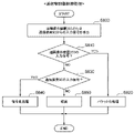
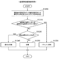
- FIG. 7 shows a control flow executed by the display control unit 221 of the remote control device 201 of this embodiment. This control flow is executed by inputting a signal from the communication device 90 shown in FIG.
- a predicted trajectory is drawn as a video signal from the calculation result of the predicted trajectory calculator 220 detected at S700.
- a predicted video of the vehicle body predicted video data of the pseudo hydraulic excavator 1 viewed from the camera (camera viewpoint) generated based on the calculation result (predicted trajectory) of the predicted trajectory calculation unit 220) , which is also referred to as a pseudo-camera image in this paper
- a symbol indicating the direction and magnitude of the gradated vector after each second is also referred to as a pseudo-camera image in this paper
- the video signal superimposed at S720 is output to the display device 202, and the process ends.
- the display device 202 based on the video signal sent from the display control unit 221, the predicted trajectory (pseudo camera video) and the vehicle-mounted camera video of the hydraulic excavator 1 (actual video of the work site) are displayed on the same screen. are superimposed (simultaneously) above (see FIG. 13).
- FIG. 8 shows a control flow executed by the communication control unit 222 of the remote control device 201 of this embodiment. This control flow is executed by inputting a signal from the remote control device 203 or the communication device 90 shown in FIG.
- the input signal is packetized and transmitted to the communication device 90, and the process ends.
- the control device (remote control device) 201 of the remote control device 200 of the present embodiment receives the camera image of the work site captured by the vehicle-mounted camera 91 and the vehicle body information of the work machine (hydraulic excavator) 1. a communication control unit 222; a predicted trajectory calculation unit 220 that calculates a predicted trajectory of the working machine (hydraulic excavator) 1 from the vehicle body information and outputs predicted trajectory data to be displayed as an image on the display device 202; and a display control unit 221 that causes the display device 202 to display (simultaneously) an image and an image of the predicted trajectory on the same screen.
- the display control unit 221 causes the display device 202 to display the camera image and the predicted trajectory image in a superimposed manner on the same screen.
- the display control unit 221 generates a pseudo camera image, which is a (pseudo) predicted image of the working machine (hydraulic excavator) 1 when viewed from the vehicle-mounted camera 91 based on the predicted trajectory,
- the camera image and the pseudo camera image are superimposed and displayed on the display device 202 on the same screen.
- the remote control device 200 of the present embodiment superimposes the vehicle-mounted camera image and the predicted trajectory image and displays them to the remote operator, thereby transmitting the vehicle status to the operator without depending on the delay of the image data. , visually presents the video delay to the pilot.
- the operator can display the image of the predicted trajectory.
- the current status of the vehicle can be recognized.
- a pseudo camera image (a (pseudo) predicted image of the hydraulic excavator 1 when viewed from a camera generated based on the predicted trajectory)
- the actual camera image the difference in
- remote operation can be performed efficiently and safely.
- FIG. 9 is a functional block diagram of the remote control device 201a of the remote control device 200a according to this embodiment.
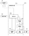
- the remote control device 201a of the remote control device 200a of the second embodiment is additionally configured with a communication status determination section 223 and a communication status transmission section 224 as shown in FIG.
- the video signal superimposed by the display control section 221 is input to the communication status determination section 223 .
- the communication status determination unit 223 determines the transmission status of the communication line between the hydraulic excavator 1 and the remote control device 200a from the difference between the predicted trajectory (pseudo camera image) of the video signal input from the display control unit 221 and the in-vehicle camera image. do.
- the determination result is output to communication status transmission section 224 and display device 202 .
- the communication status transmission unit 224 transmits the determination result of the communication status determination unit 223 (determination result of the transmission status of the communication line) to the communication device 90 of the hydraulic excavator 1 via the communication control unit 222a.
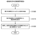
- FIG. 10 shows a control flowchart of the communication status determination section 223 of the remote control device 201a of the second embodiment. This control flow is executed by inputting the output of the display control unit 221 shown in FIG.
- the communication status is determined from the input signal from the display control unit 221 detected at S1000.
- the delay time is calculated based on the delay calculation table from the difference amount distribution of each feature point of the real camera image and the pseudo camera image in the superimposed image. After the calculation of the delay time of the communication line is completed, the process proceeds to S1020.
- the delay time calculated at S1010 is output to the communication status transmission unit 224 and the display device 202, and the process ends.
- the delay time which is the determination result sent from the communication status determination unit 223, is displayed on the same screen together with the predicted trajectory (pseudo camera image) and the in-vehicle camera image of the hydraulic excavator 1 (actual image of the work site). displayed above (see FIG. 13).
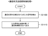
- FIG. 11 shows a control flowchart of the communication status transmitting section 224 of the remote control device 201a of the second embodiment. This control flow is executed by inputting the output of the communication status determination unit 223 shown in FIG.
- the input signal from the communication status determination unit 223 detected at S1100 is output to the communication control unit 222a.
- the input signal is converted as one of the operation signals of the remote controller 203 and output to the communication control unit 222a. After outputting the input signal to the communication control unit 222a, the process ends.
- FIG. 12 shows a control flow executed by the communication control unit 222a of the remote control device 201a of the second embodiment. This control flow is executed by inputting a signal from the remote control device 203, the communication device 90, or the communication status transmission section 224 shown in FIG.
- the input signal is packetized and transmitted to the communication device 90, and the process ends.
- the hydraulic excavator (working machine) 1 of the present embodiment suppresses the vehicle body motion according to the determination result of the communication status determination section 223 received from the communication status transmission section 224 .
- the hydraulic excavator 1 has a table of operation speed upper limit values corresponding to delay times determined by the communication status determination unit 223. As the delay time determined by the communication status determination unit 223 increases, the operation speed upper limit value increases. to slow down.
- the hydraulic excavator 1 stops all drive units when the communication status determination unit 223 determines that communication has been interrupted.
- the communication status transmission unit 224 directly transmits the determination result (delay time) of the communication status determination unit 223 to the communication device 90 of the hydraulic excavator 1.
- the communication status determination unit 223 calculates The determination result (delay time) of the communication status determination unit 223 may be transmitted to the communication device 90 of the hydraulic excavator 1 only when the delay time determined is greater than a predetermined threshold value and a communication failure is determined.
- the remote control device 200a of this embodiment determines the transmission status of the communication line between the working machine (hydraulic excavator) 1 and the remote control device 200 from the difference between the camera image and the pseudo camera image.
- a communication status determination unit 223 is further provided.
- the communication status determination unit 223 causes the display device 202 to display the determination result of the transmission status of the communication line.
- a communication status transmission unit 224 is further provided for transmitting the determination result of the transmission status of the communication line to the work machine (hydraulic excavator) 1 (for example, when the communication status determination unit 223 determines that there is a communication failure). Prepare.
- the delay situation can be visually transmitted to the operator as in the first embodiment.
- the delay time which is the delay determination result, can also be obtained.
- the delay determination result can be transmitted to the hydraulic excavator 1, the hydraulic excavator 1 can be controlled according to the delay determination result.
- the predicted trajectory (pseudo camera image) and the vehicle-mounted camera image of the hydraulic excavator 1 (actual image of the work site) are superimposed (simultaneously) on the same screen. Although it is displayed (see FIG. 13), for example, as shown in FIG. It may be displayed above but in a different position (see FIG. 14).
- the present invention is not limited to the above-described embodiments, and includes various modifications.
- the above-described embodiments have been described in detail in order to explain the present invention in an easy-to-understand manner, and are not necessarily limited to those having all the configurations described.
- part of the configuration of one embodiment can be replaced with the configuration of another embodiment, and the configuration of another embodiment can be added to the configuration of one embodiment.
- each function of the controller of the above-described embodiments may be implemented in hardware by designing part or all of them, for example, in an integrated circuit.
- each function may be realized by software by a processor interpreting and executing a program for realizing each function.
- Information such as programs, tables, files, etc. that realize each function can be stored in storage devices in the controller, recording devices such as hard disks and SSDs (Solid State Drives), or recording media such as IC cards, SD cards, and DVDs. can be placed in
- Remote control device control device 202... Display device 203... Remote control device 204... Cockpit 211... Communication interface 212... Central processing unit (CPU) 213 ... read only memory (ROM) 214 Random Access Memory (RAM) 215... Input interface 216... Output interface 220... Predicted trajectory calculation unit 221... Display control unit 222... Communication control unit 223... Communication status determination unit (second embodiment) 224: Communication status transmission unit (second embodiment)
Landscapes
- Engineering & Computer Science (AREA)
- General Engineering & Computer Science (AREA)
- Mining & Mineral Resources (AREA)
- Civil Engineering (AREA)
- Structural Engineering (AREA)
- Physics & Mathematics (AREA)
- Remote Sensing (AREA)
- Radar, Positioning & Navigation (AREA)
- Aviation & Aerospace Engineering (AREA)
- General Physics & Mathematics (AREA)
- Automation & Control Theory (AREA)
- Chemical & Material Sciences (AREA)
- Mechanical Engineering (AREA)
- Combustion & Propulsion (AREA)
- Fluid Mechanics (AREA)
- Multimedia (AREA)
- Signal Processing (AREA)
- Operation Control Of Excavators (AREA)
- Component Parts Of Construction Machinery (AREA)
- Control Of Vehicle Engines Or Engines For Specific Uses (AREA)
- Closed-Circuit Television Systems (AREA)
- Traffic Control Systems (AREA)
- Control Of Position, Course, Altitude, Or Attitude Of Moving Bodies (AREA)
Abstract
Description
<基本構成>
図1は、本発明の第1実施形態に係る作業機械1の遠隔操縦システム100の例を示す図である。遠隔操縦システム100は、作業機械1を遠隔操作する。本実施形態においては、作業機械1が油圧ショベルであることとする。図2は、本発明の第1実施形態に係る油圧ショベル(作業機械)1の制御コントローラを油圧駆動装置と共に示す図であり、図3は、図2中の電磁弁ユニット160の詳細図である。
図3に示すように、電磁弁ユニット(図3ではフロント制御用油圧ユニット部分のみを表示)160は、一次ポート側がポンプライン143aを介してパイロットポンプ30に接続され、パイロットポンプ30からのパイロット圧を減圧してパイロットライン144a~146bに出力する電磁比例弁54a~56bと、図3では紙面の都合上省略しているが(図2を併せて参照)、同様にパイロットポンプ30からのパイロット圧を減圧してパイロットライン147a~149bに出力する電磁比例弁57a~59bを備えている。
図4は、本実施形態に係る遠隔操縦装置200の遠隔操縦制御装置201が備えるハードウェア構成図である。図4において遠隔操縦制御装置201は、通信インターフェース211と、プロセッサである中央処理装置(CPU)212と、記憶装置であるリードオンリーメモリ(ROM)213及びランダムアクセスメモリ(RAM)214と、入力インターフェース215と、出力インターフェース216とを有している。
本実施形態の遠隔操縦制御装置201の予測軌跡演算部220で実施される演算フローを図6に示す。この制御フローは、図5で示す通信装置90からの信号が通信制御部222から入力されることで実施される。
本実施形態の遠隔操縦制御装置201の表示制御部221で実施される制御フローを図7に示す。この制御フローは、図5で示す通信装置90からの信号が通信制御部222から入力され、予測軌跡演算部220からの演算結果が入力されることで実施される。
本実施形態の遠隔操縦制御装置201の通信制御部222で実施される制御フローを図8に示す。この制御フローは、図5で示す遠隔操作装置203または通信装置90から信号が入力されることで実施される。
上記のように、本実施形態の遠隔操縦装置200の制御装置(遠隔操縦制御装置)201は、車載カメラ91で撮影した作業現場のカメラ映像および作業機械(油圧ショベル)1の車体情報を受信する通信制御部222と、前記車体情報から前記作業機械(油圧ショベル)1の予測軌跡を演算し、表示装置202に映像として表示するための予測軌跡データを出力する予測軌跡演算部220と、前記カメラ映像と前記予測軌跡の映像とを前記表示装置202に同画面上で(同時に)表示させる表示制御部221と、を備える。
本発明の第2実施形態について図9~12を用いて説明する。図9は、本実施形態に係る遠隔操縦装置200aの遠隔操縦制御装置201aの機能ブロック図である。
通信状況判定部223は、表示制御部221から入力される映像信号の予測軌跡(疑似カメラ映像)と車載カメラ映像との差分から、油圧ショベル1と遠隔操縦装置200aの通信回線の伝送状況を判定する。その判定結果を、通信状況送信部224および表示装置202へ出力する。
図10に本第2実施形態の遠隔操縦制御装置201aの通信状況判定部223の制御フローチャートを示す。この制御フローは、図9で示す表示制御部221の出力が入力されることで実施される。
図11に本第2実施形態の遠隔操縦制御装置201aの通信状況送信部224の制御フローチャートを示す。この制御フローは、図9で示す通信状況判定部223の出力が入力されることで実施される。
本第2実施形態の遠隔操縦制御装置201aの通信制御部222aで実施される制御フローを図12に示す。この制御フローは、図9で示す遠隔操作装置203または通信装置90または通信状況送信部224から信号が入力されることで実施される。
本実施形態の油圧ショベル(作業機械)1は、通信状況送信部224から受信する通信状況判定部223の判定結果に応じて車体動作を抑制する。例えば、油圧ショベル1は、通信状況判定部223の判定結果である遅延時間に対する動作速度上限値のテーブルを持ち、通信状況判定部223の判定結果の遅延時間が大きくなればなるほど動作速度の上限値を抑制して遅く動作するようになる。あるいは、油圧ショベル1は、通信状況判定部223が通信途絶と判定した場合、全ての駆動部を停止させる。
上記のように、本実施形態の遠隔操縦装置200aは、前記カメラ映像と前記疑似カメラ映像との差分から前記作業機械(油圧ショベル)1と前記遠隔操縦装置200の通信回線の伝送状況を判定する通信状況判定部223をさらに備える。
2…作業フロント(作業装置)
3…走行体
4…走行油圧モータ
5…旋回油圧モータ
6…ブーム
7…アーム
8…バケット
9…バケットリンク
10…操作装置
11…エンジン
12…運転室
15…流量制御弁
16…負荷検出装置
20…油圧ポンプ
30…パイロットポンプ
31…車体傾斜角センサ
32…旋回角度センサ
39…ロック弁
40…制御コントローラ
54~59…電磁比例弁
61…ブームシリンダ
62…ブーム角度センサ
71…アームシリンダ
72…アーム角度センサ
81…バケットシリンダ
82…バケット角度センサ
90…通信装置
91…車載カメラ
100…遠隔操縦システム
143a…ポンプライン
144a~149b…パイロットライン
150a~155b…油圧駆動部
160…電磁弁ユニット
170…タンク
200…遠隔操縦装置
201…遠隔操縦制御装置(制御装置)
202…表示装置
203…遠隔操作装置
204…操縦席
211…通信インターフェース
212…中央処理装置(CPU)
213…リードオンリーメモリ(ROM)
214…ランダムアクセスメモリ(RAM)
215…入力インターフェース
216…出力インターフェース
220…予測軌跡演算部
221…表示制御部
222…通信制御部
223…通信状況判定部(第2実施形態)
224…通信状況送信部(第2実施形態)
Claims (8)
- 作業機械へ操作信号を送信して前記作業機械を遠隔地から操縦する制御装置を備えた遠隔操縦装置であって、
前記制御装置は、
カメラで撮影した作業現場のカメラ映像および前記作業機械の車体情報を受信する通信制御部と、
前記車体情報から前記作業機械の予測軌跡を演算し、表示装置に映像として表示するための予測軌跡データを出力する予測軌跡演算部と、
前記カメラ映像と前記予測軌跡の映像とを前記表示装置に同画面上で表示させる表示制御部と、を備える遠隔操縦装置。 - 前記表示制御部は、前記カメラ映像と前記予測軌跡の映像とを前記表示装置に同画面上で重畳して表示させる請求項1に記載の遠隔操縦装置。
- 前記表示制御部は、前記カメラ映像と前記予測軌跡の映像を前記表示装置に同画面上で異なる位置に表示させる請求項1に記載の遠隔操縦装置。
- 前記表示制御部は、前記予測軌跡に基づいて前記カメラから視た場合の前記作業機械の予測映像である疑似カメラ映像を生成し、前記カメラ映像と前記疑似カメラ映像とを前記表示装置に同画面上で重畳して表示させる請求項1に記載の遠隔操縦装置。
- 前記カメラ映像と前記疑似カメラ映像との差分から前記作業機械と前記遠隔操縦装置の通信回線の伝送状況を判定する通信状況判定部をさらに備える請求項4に記載の遠隔操縦装置。
- 前記通信状況判定部は、前記通信回線の伝送状況の判定結果を前記表示装置に表示させる請求項5に記載の遠隔操縦装置。
- 前記通信回線の伝送状況の判定結果を前記作業機械に送信する通信状況送信部をさらに備える請求項5に記載の遠隔操縦装置。
- 前記通信状況判定部により通信障害があったと判定された場合、前記通信回線の伝送状況の判定結果を前記作業機械に送信する通信状況送信部をさらに備える請求項5に記載の遠隔操縦装置。
Priority Applications (5)
| Application Number | Priority Date | Filing Date | Title |
|---|---|---|---|
| US18/023,513 US12416134B2 (en) | 2021-03-15 | 2022-02-18 | Remote operation device for a work machine |
| EP22771001.9A EP4311228A4 (en) | 2021-03-15 | 2022-02-18 | REMOTE ACTUATION DEVICE |
| JP2023506893A JP7466055B2 (ja) | 2021-03-15 | 2022-02-18 | 遠隔操縦装置 |
| CN202280005784.XA CN116034200B (zh) | 2021-03-15 | 2022-02-18 | 远程操纵装置 |
| KR1020237006235A KR102874684B1 (ko) | 2021-03-15 | 2022-02-18 | 원격 조종 장치 |
Applications Claiming Priority (2)
| Application Number | Priority Date | Filing Date | Title |
|---|---|---|---|
| JP2021-041732 | 2021-03-15 | ||
| JP2021041732 | 2021-03-15 |
Publications (1)
| Publication Number | Publication Date |
|---|---|
| WO2022196242A1 true WO2022196242A1 (ja) | 2022-09-22 |
Family
ID=83322296
Family Applications (1)
| Application Number | Title | Priority Date | Filing Date |
|---|---|---|---|
| PCT/JP2022/006559 Ceased WO2022196242A1 (ja) | 2021-03-15 | 2022-02-18 | 遠隔操縦装置 |
Country Status (6)
| Country | Link |
|---|---|
| US (1) | US12416134B2 (ja) |
| EP (1) | EP4311228A4 (ja) |
| JP (1) | JP7466055B2 (ja) |
| KR (1) | KR102874684B1 (ja) |
| CN (1) | CN116034200B (ja) |
| WO (1) | WO2022196242A1 (ja) |
Cited By (5)
| Publication number | Priority date | Publication date | Assignee | Title |
|---|---|---|---|---|
| WO2024173601A1 (en) * | 2023-02-14 | 2024-08-22 | Zimeno Inc. | Vehicle tool guidance system |
| JP2025016172A (ja) * | 2023-07-21 | 2025-01-31 | トヨタ自動車株式会社 | 遠隔支援システム |
| US12441199B2 (en) | 2022-12-01 | 2025-10-14 | Zimeno Inc. | Motor output control system |
| US12448756B2 (en) | 2022-11-30 | 2025-10-21 | Zimeno Inc. | Vehicle vision |
| WO2026075061A1 (ja) * | 2024-10-04 | 2026-04-09 | 株式会社小松製作所 | 作業機械の制御システム及び作業機械の制御方法 |
Families Citing this family (2)
| Publication number | Priority date | Publication date | Assignee | Title |
|---|---|---|---|---|
| WO2025249608A1 (ko) * | 2024-05-30 | 2025-12-04 | 볼보 컨스트럭션 이큅먼트 에이비 | 스윙 어시스트 기능을 갖는 건설기계의 원격조종 시스템 |
| US20260062259A1 (en) * | 2024-08-27 | 2026-03-05 | Caterpillar Inc. | System and method for determining position of a pipelayer boom |
Citations (6)
| Publication number | Priority date | Publication date | Assignee | Title |
|---|---|---|---|---|
| JP2012066724A (ja) * | 2010-09-24 | 2012-04-05 | Denso Corp | 車両用の後退駐車支援装置および後退駐車支援装置用のプログラム |
| JP2014004930A (ja) * | 2012-06-25 | 2014-01-16 | Aisin Seiki Co Ltd | 駐車支援装置、駐車支援方法、及び駐車支援プログラム |
| JP2014071778A (ja) * | 2012-09-28 | 2014-04-21 | Equos Research Co Ltd | 車両 |
| JP2018152652A (ja) * | 2017-03-10 | 2018-09-27 | 株式会社Jvcケンウッド | 運転支援装置、運転支援方法およびプログラム |
| JP2019054464A (ja) | 2017-09-15 | 2019-04-04 | 株式会社小松製作所 | 表示システム、表示方法、及び表示装置 |
| JP2020132431A (ja) * | 2019-02-21 | 2020-08-31 | 株式会社豊田自動織機 | 産業車両用走行支援装置 |
Family Cites Families (11)
| Publication number | Priority date | Publication date | Assignee | Title |
|---|---|---|---|---|
| JP3939564B2 (ja) * | 2002-02-12 | 2007-07-04 | アルパイン株式会社 | ナビゲーション装置 |
| US9441985B2 (en) * | 2012-07-25 | 2016-09-13 | Rockwell Collins, Inc. | Future scene generating system, device, and method for a remotely-operated vehicle |
| US11281207B2 (en) * | 2013-03-19 | 2022-03-22 | Robotic Research Opco, Llc | Delayed telop aid |
| US9519286B2 (en) * | 2013-03-19 | 2016-12-13 | Robotic Research, Llc | Delayed telop aid |
| JP6832548B2 (ja) * | 2016-08-31 | 2021-02-24 | 株式会社小松製作所 | 作業機械の画像表示システム、作業機械の遠隔操作システム、作業機械及び作業機械の画像表示方法 |
| US10678237B2 (en) * | 2016-12-22 | 2020-06-09 | Panasonic Intellectual Property Corporation Of America | Information processing apparatus, operated vehicle, information processing method, and recording medium storing program |
| JP2019016188A (ja) * | 2017-07-07 | 2019-01-31 | 株式会社日立製作所 | 移動体遠隔操作システムおよび移動体遠隔操作方法 |
| US10425622B2 (en) * | 2017-07-18 | 2019-09-24 | The United States Of America As Represented By The Secretary Of The Army | Method of generating a predictive display for tele-operation of a remotely-operated ground vehicle |
| CN107566685B (zh) * | 2017-09-26 | 2020-10-27 | 联想(北京)有限公司 | 一种图像数据处理方法及电子设备 |
| EP3934241A4 (en) * | 2019-02-28 | 2022-04-20 | Sumitomo Heavy Industries, Ltd. | DISPLAY DEVICE, SHOVEL, INFORMATION PROCESSING DEVICE |
| US11615707B2 (en) * | 2019-05-29 | 2023-03-28 | Deere & Company | Guidance display system for work vehicles and work implements |
-
2022
- 2022-02-18 CN CN202280005784.XA patent/CN116034200B/zh active Active
- 2022-02-18 US US18/023,513 patent/US12416134B2/en active Active
- 2022-02-18 WO PCT/JP2022/006559 patent/WO2022196242A1/ja not_active Ceased
- 2022-02-18 EP EP22771001.9A patent/EP4311228A4/en active Pending
- 2022-02-18 KR KR1020237006235A patent/KR102874684B1/ko active Active
- 2022-02-18 JP JP2023506893A patent/JP7466055B2/ja active Active
Patent Citations (6)
| Publication number | Priority date | Publication date | Assignee | Title |
|---|---|---|---|---|
| JP2012066724A (ja) * | 2010-09-24 | 2012-04-05 | Denso Corp | 車両用の後退駐車支援装置および後退駐車支援装置用のプログラム |
| JP2014004930A (ja) * | 2012-06-25 | 2014-01-16 | Aisin Seiki Co Ltd | 駐車支援装置、駐車支援方法、及び駐車支援プログラム |
| JP2014071778A (ja) * | 2012-09-28 | 2014-04-21 | Equos Research Co Ltd | 車両 |
| JP2018152652A (ja) * | 2017-03-10 | 2018-09-27 | 株式会社Jvcケンウッド | 運転支援装置、運転支援方法およびプログラム |
| JP2019054464A (ja) | 2017-09-15 | 2019-04-04 | 株式会社小松製作所 | 表示システム、表示方法、及び表示装置 |
| JP2020132431A (ja) * | 2019-02-21 | 2020-08-31 | 株式会社豊田自動織機 | 産業車両用走行支援装置 |
Non-Patent Citations (1)
| Title |
|---|
| See also references of EP4311228A4 |
Cited By (5)
| Publication number | Priority date | Publication date | Assignee | Title |
|---|---|---|---|---|
| US12448756B2 (en) | 2022-11-30 | 2025-10-21 | Zimeno Inc. | Vehicle vision |
| US12441199B2 (en) | 2022-12-01 | 2025-10-14 | Zimeno Inc. | Motor output control system |
| WO2024173601A1 (en) * | 2023-02-14 | 2024-08-22 | Zimeno Inc. | Vehicle tool guidance system |
| JP2025016172A (ja) * | 2023-07-21 | 2025-01-31 | トヨタ自動車株式会社 | 遠隔支援システム |
| WO2026075061A1 (ja) * | 2024-10-04 | 2026-04-09 | 株式会社小松製作所 | 作業機械の制御システム及び作業機械の制御方法 |
Also Published As
| Publication number | Publication date |
|---|---|
| US20230323630A1 (en) | 2023-10-12 |
| JP7466055B2 (ja) | 2024-04-11 |
| US12416134B2 (en) | 2025-09-16 |
| KR20230044253A (ko) | 2023-04-03 |
| CN116034200A (zh) | 2023-04-28 |
| KR102874684B1 (ko) | 2025-10-22 |
| JPWO2022196242A1 (ja) | 2022-09-22 |
| CN116034200B (zh) | 2025-10-21 |
| EP4311228A4 (en) | 2025-02-19 |
| EP4311228A1 (en) | 2024-01-24 |
Similar Documents
| Publication | Publication Date | Title |
|---|---|---|
| JP7466055B2 (ja) | 遠隔操縦装置 | |
| US12264456B2 (en) | Shovel | |
| KR102024701B1 (ko) | 작업 기계 | |
| KR102091504B1 (ko) | 건설 기계 | |
| EP3951077B1 (en) | Excavator and construction system | |
| KR20190025992A (ko) | 작업 기계 | |
| WO2018051511A1 (ja) | 作業機械 | |
| KR20210120085A (ko) | 건설 기계 | |
| JPWO2018043299A1 (ja) | 作業機械の画像表示システム、作業機械の遠隔操作システム、作業機械及び作業機械の画像表示方法 | |
| CN113631776B (zh) | 挖土机及施工系统 | |
| KR20200028993A (ko) | 작업 기계 | |
| CN114174595B (zh) | 挖土机及挖土机的控制装置 | |
| JP6615058B2 (ja) | 作業機械 | |
| CN116057238B (zh) | 作业机械 | |
| JP7704501B2 (ja) | 作業機械 | |
| JP7809562B2 (ja) | 作業機械 | |
| EP4394134B1 (en) | Shovel | |
| JP2025039396A (ja) | ショベル、及びショベルの遠隔操作システム | |
| JP2025079734A (ja) | 作業機械の操作システム、及び作業機械の遠隔操作装置 | |
| JP2026004736A (ja) | 作業機械、及び、作業機械用の遠隔操作システム | |
| JP2026011877A (ja) | 作業機械、及び作業機械用の操作システム | |
| JP2025104958A (ja) | ショベル及びショベルシステム | |
| JP2024159066A (ja) | ショベル |
Legal Events
| Date | Code | Title | Description |
|---|---|---|---|
| 121 | Ep: the epo has been informed by wipo that ep was designated in this application |
Ref document number: 22771001 Country of ref document: EP Kind code of ref document: A1 |
|
| ENP | Entry into the national phase |
Ref document number: 20237006235 Country of ref document: KR Kind code of ref document: A |
|
| ENP | Entry into the national phase |
Ref document number: 2023506893 Country of ref document: JP Kind code of ref document: A |
|
| WWE | Wipo information: entry into national phase |
Ref document number: 2022771001 Country of ref document: EP |
|
| NENP | Non-entry into the national phase |
Ref country code: DE |
|
| ENP | Entry into the national phase |
Ref document number: 2022771001 Country of ref document: EP Effective date: 20231016 |
|
| WWG | Wipo information: grant in national office |
Ref document number: 18023513 Country of ref document: US |
|
| WWG | Wipo information: grant in national office |
Ref document number: 202280005784.X Country of ref document: CN |