WO2022196323A1 - システム及びプログラム - Google Patents
システム及びプログラム Download PDFInfo
- Publication number
- WO2022196323A1 WO2022196323A1 PCT/JP2022/008269 JP2022008269W WO2022196323A1 WO 2022196323 A1 WO2022196323 A1 WO 2022196323A1 JP 2022008269 W JP2022008269 W JP 2022008269W WO 2022196323 A1 WO2022196323 A1 WO 2022196323A1
- Authority
- WO
- WIPO (PCT)
- Prior art keywords
- container
- articles
- sorter
- processor
- article
- Prior art date
- Legal status (The legal status is an assumption and is not a legal conclusion. Google has not performed a legal analysis and makes no representation as to the accuracy of the status listed.)
- Ceased
Links
Images






Classifications
-
- B—PERFORMING OPERATIONS; TRANSPORTING
- B65—CONVEYING; PACKING; STORING; HANDLING THIN OR FILAMENTARY MATERIAL
- B65G—TRANSPORT OR STORAGE DEVICES, e.g. CONVEYORS FOR LOADING OR TIPPING, SHOP CONVEYOR SYSTEMS OR PNEUMATIC TUBE CONVEYORS
- B65G47/00—Article or material-handling devices associated with conveyors; Methods employing such devices
- B65G47/34—Devices for discharging articles or materials from conveyor
- B65G47/46—Devices for discharging articles or materials from conveyor and distributing, e.g. automatically, to desired points
-
- B—PERFORMING OPERATIONS; TRANSPORTING
- B65—CONVEYING; PACKING; STORING; HANDLING THIN OR FILAMENTARY MATERIAL
- B65G—TRANSPORT OR STORAGE DEVICES, e.g. CONVEYORS FOR LOADING OR TIPPING, SHOP CONVEYOR SYSTEMS OR PNEUMATIC TUBE CONVEYORS
- B65G1/00—Storing articles, individually or in orderly arrangement, in warehouses or magazines
- B65G1/02—Storage devices
- B65G1/04—Storage devices mechanical
- B65G1/06—Storage devices mechanical with means for presenting articles for removal at predetermined position or level
- B65G1/065—Storage devices mechanical with means for presenting articles for removal at predetermined position or level with self propelled cars
-
- B—PERFORMING OPERATIONS; TRANSPORTING
- B07—SEPARATING SOLIDS FROM SOLIDS; SORTING
- B07C—POSTAL SORTING; SORTING INDIVIDUAL ARTICLES, OR BULK MATERIAL FIT TO BE SORTED PIECE-MEAL, e.g. BY PICKING
- B07C5/00—Sorting according to a characteristic or feature of the articles or material being sorted, e.g. by control effected by devices which detect or measure such characteristic or feature; Sorting by manually actuated devices, e.g. switches
- B07C5/36—Sorting apparatus characterised by the means used for distribution
-
- B—PERFORMING OPERATIONS; TRANSPORTING
- B65—CONVEYING; PACKING; STORING; HANDLING THIN OR FILAMENTARY MATERIAL
- B65G—TRANSPORT OR STORAGE DEVICES, e.g. CONVEYORS FOR LOADING OR TIPPING, SHOP CONVEYOR SYSTEMS OR PNEUMATIC TUBE CONVEYORS
- B65G1/00—Storing articles, individually or in orderly arrangement, in warehouses or magazines
- B65G1/02—Storage devices
- B65G1/04—Storage devices mechanical
-
- B—PERFORMING OPERATIONS; TRANSPORTING
- B65—CONVEYING; PACKING; STORING; HANDLING THIN OR FILAMENTARY MATERIAL
- B65G—TRANSPORT OR STORAGE DEVICES, e.g. CONVEYORS FOR LOADING OR TIPPING, SHOP CONVEYOR SYSTEMS OR PNEUMATIC TUBE CONVEYORS
- B65G37/00—Combinations of mechanical conveyors of the same kind, or of different kinds, of interest apart from their application in particular machines or use in particular manufacturing processes
-
- B—PERFORMING OPERATIONS; TRANSPORTING
- B65—CONVEYING; PACKING; STORING; HANDLING THIN OR FILAMENTARY MATERIAL
- B65G—TRANSPORT OR STORAGE DEVICES, e.g. CONVEYORS FOR LOADING OR TIPPING, SHOP CONVEYOR SYSTEMS OR PNEUMATIC TUBE CONVEYORS
- B65G47/00—Article or material-handling devices associated with conveyors; Methods employing such devices
- B65G47/74—Feeding, transfer, or discharging devices of particular kinds or types
- B65G47/94—Devices for flexing or tilting travelling structures; Throw-off carriages
- B65G47/96—Devices for tilting links or platform
-
- G—PHYSICS
- G06—COMPUTING OR CALCULATING; COUNTING
- G06Q—INFORMATION AND COMMUNICATION TECHNOLOGY [ICT] SPECIALLY ADAPTED FOR ADMINISTRATIVE, COMMERCIAL, FINANCIAL, MANAGERIAL OR SUPERVISORY PURPOSES; SYSTEMS OR METHODS SPECIALLY ADAPTED FOR ADMINISTRATIVE, COMMERCIAL, FINANCIAL, MANAGERIAL OR SUPERVISORY PURPOSES, NOT OTHERWISE PROVIDED FOR
- G06Q10/00—Administration; Management
- G06Q10/08—Logistics, e.g. warehousing, loading or distribution; Inventory or stock management
-
- G—PHYSICS
- G06—COMPUTING OR CALCULATING; COUNTING
- G06Q—INFORMATION AND COMMUNICATION TECHNOLOGY [ICT] SPECIALLY ADAPTED FOR ADMINISTRATIVE, COMMERCIAL, FINANCIAL, MANAGERIAL OR SUPERVISORY PURPOSES; SYSTEMS OR METHODS SPECIALLY ADAPTED FOR ADMINISTRATIVE, COMMERCIAL, FINANCIAL, MANAGERIAL OR SUPERVISORY PURPOSES, NOT OTHERWISE PROVIDED FOR
- G06Q10/00—Administration; Management
- G06Q10/08—Logistics, e.g. warehousing, loading or distribution; Inventory or stock management
- G06Q10/087—Inventory or stock management, e.g. order filling, procurement or balancing against orders
-
- B—PERFORMING OPERATIONS; TRANSPORTING
- B07—SEPARATING SOLIDS FROM SOLIDS; SORTING
- B07C—POSTAL SORTING; SORTING INDIVIDUAL ARTICLES, OR BULK MATERIAL FIT TO BE SORTED PIECE-MEAL, e.g. BY PICKING
- B07C2501/00—Sorting according to a characteristic or feature of the articles or material to be sorted
- B07C2501/0063—Using robots
Definitions
- the embodiments of the present invention relate to systems and programs.
- a system uses a sorter to put items into each chute. Such systems sort items into chutes depending on where the items are sorted.
- the system when the number of sorting destinations is greater than the number of chutes, the system requires workers to re-sort the articles after sorting them into predetermined chutes.
- the system includes an information processing device, a sorter, and an automatic guided vehicle.
- the sorter includes trays and an input mechanism.
- the tray loads articles.
- a loading mechanism loads the article from the tray into the first container or the automatic transport vehicle.
- the automatic guided vehicle includes a loading mechanism and a moving mechanism.
- the loading mechanism loads the article and puts the article into the second container.
- a moving mechanism moves the loading mechanism.
- the information processing device includes a communication unit and a processor.
- the communication unit communicates with an external device, the sorter, and the automatic guided vehicle.
- the processor acquires sorting destination information indicating a sorting destination of the articles from the external device through the communication unit, and selects the first container or the second container as a sorting container into which the articles are put based on the sorting destination information.
- a control signal is transmitted through the communication unit to cause the sorter to put the articles into the first container
- the second container is specified and transmitting a control signal for causing the sorter to put the articles into the automatic guided vehicle through the communication unit, and sending a control signal for making the automatic guided vehicle put the articles into the second container through the communication unit.
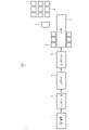
- FIG. 1 is a block diagram showing a configuration example of a sorting system according to an embodiment.
- FIG. 2 is a block diagram showing a configuration example of a control system of the sorting system according to the embodiment.
- FIG. 3 is a block diagram showing a configuration example of the partitioning control device according to the embodiment.
- FIG. 4 is a block diagram showing a configuration example of the sorter control device according to the embodiment.
- FIG. 5 is a block diagram showing a configuration example of the AGV control device according to the embodiment.
- FIG. 6 is a perspective view of the AGV according to the embodiment.
- FIG. 7 is a top view of the AGV according to the embodiment.
- FIG. 8 is a side view of the AGV according to the embodiment.
- FIG. 1 is a block diagram showing a configuration example of a sorting system according to an embodiment.
- FIG. 2 is a block diagram showing a configuration example of a control system of the sorting system according to the embodiment.
- FIG. 3 is a block
- FIG. 9 is a block diagram showing a configuration example of an AGV according to the embodiment;
- FIG. 10 is a diagram showing an operation example of the AGV according to the embodiment.
- FIG. 11 is a diagram illustrating a configuration example of a first container according to the embodiment;
- FIG. 12 is a diagram showing a modification of the first container according to the embodiment;
- FIG. 13 is a diagram illustrating an installation example of the sorter and the first container according to the embodiment;
- FIG. 14 is a diagram illustrating an operation example of the sorter according to the embodiment;
- 15 is a diagram illustrating an operation example of the sorter according to the embodiment;
- FIG. 16 is a diagram illustrating a configuration example of sorting destination information according to the embodiment.
- FIG. 17 is a diagram illustrating an operation example of the sorting system according to the embodiment.
- FIG. 18 is a diagram illustrating an operation example of the sorting system according to the embodiment;
- FIG. 19 is a flow chart showing an operation example of the sorting system according to the embodiment.
- a sorting system sorts each article into sorting destinations.
- the sorting system uses a sorter and an Automated Guided Vehicle (AGV) to put articles into containers corresponding to sorting destinations.
- AGV Automated Guided Vehicle
- the sorting system loads items directly from the sorter into bins. Also, the sorting system transfers the articles from the sorter to the AGV and puts them into the container from the AGV.
- FIG. 1 shows a configuration example of a sorting system 100 according to an embodiment.
- the sorting system 100 comprises an input device 1, a singulator 2, a scanner 3, an induction 4, a sorter 5, an AGV 7, a first container 8 and a second container 9, and so on.
- the sorting system 100 conveys articles in the order of the input device 1, the singulator 2, the scanner 3, the induction 4 and the sorter 5.
- the loading device 1 loads articles into the sorting system 100 .
- the input device 1 receives input of articles from a worker, a robot, or the like.
- the throwing device 1 throws the thrown article into the singulator 2 .
- the singulator 2 arranges the thrown items in a predetermined direction.
- the singulator 2 is composed of a conveyor or the like.
- the singulator 2 aligns the articles in a predetermined direction by pressing the articles against a wall surface using a conveyor or the like.
- the scanner 3 reads the code attached to the item.
- a code is obtained by encoding an ID that identifies an article. Further, the scanner 3 may read the character string of the ID attached to the article by character recognition processing (OCR (Optical Character Recognition) processing) or the like.
- OCR Optical Character Recognition
- the scanner 3 reads the ID from the code of the article arranged by the singulator 2.
- the induction 4 puts the articles into the sorter 5.
- the induction 4 may use a conveyor or the like to put the articles into the sorter 5, or may put the articles into the sorter 5 by an operator.
- the sorter 5 sorts the thrown-in articles into chutes.
- the sorter 5 is composed of trays, pushers, and the like.
- the sorter 5 loads articles on trays and conveys them.
- the sorter 5 uses a pusher to push the articles from the tray to the chute when the tray arrives before the predetermined chute.
- the pusher pushes the articles to a specific chute depending on where the articles are to be sorted.
- the pusher is positioned in the opposite direction to the direction in which the article is pushed out before the induction 4 places the article on the tray.
- the sorter 5 throws the articles into the first container 8 and the AGV 7 from the chute. That is, the sorter 5 puts the articles directly into the first container 8 or loads the articles on the AGV 7 .
- the sorter 5 may be composed of trays and pushers, may be composed of cross belts, or may be of another mechanism.
- the sorter 5 having trays and pushers will be described as an example.
- the first container 8 is a container into which articles are directly thrown from the sorter 5.
- a first container 8 is installed adjacent to the sorter 5 .
- the first container 8 is installed at a position (receiving position) where articles from the chute of the sorter 5 can be received.
- the first container 8 is loaded with goods from the AGV 7.
- the first container 8 has a structure that allows the AGV 7 to load articles from the surface facing the sorter 5 .
- the first container 8 is a basket car or the like.
- the first container 8 will be detailed later.
- the compartmentalization system 100 comprises a plurality of first containers 8 .
- the second container 9 is a container into which goods are thrown from the AGV 7.
- the second container 9 is open at the top or sides so that the AGV 7 can load the goods.
- the second container 9 is a cage or the like.
- the second container 9 may have the same structure as the first container 8 .
- the second container 9 is installed at a position separated from the sorter 5 by a predetermined distance. In other words, the second container 9 is installed at a position where the sorter 5 cannot directly throw in articles.
- the sorting system 100 also includes a plurality of second containers 9 .
- the AGV 7 is an automatic driving vehicle that loads and transports articles.
- AGV 7 receives articles from sorter 5 .
- the AGV 7 waits at a position where it can receive articles from the chute of the sorter 5 .
- the AGV 7 moves to a position (insertion position) where the article can be thrown into the first container 8 or the second container 9 .
- the AGV 7 dumps the articles into the first container 8 or the second container 9 .
- AGV7 will be described in detail later.
- FIG. 2 shows the control system of the sorting system 100 .
- the sorting system 100 includes a scanner 3, an induction 4, a sorter 5, a host device 6, an AGV 7, a sorting control device 10, a sorter control device 20, an AGV control device 30, and the like.
- the division control device 10 (information processing device) is connected to the scanner 3, the induction 4, the host device 6, the sorter control device 20 and the AGV control device 30. Also, the sorter control device 20 is connected to the sorter 5 . Also, the AGV control device 30 connects to the AGV 7 .
- the host device 6 transmits to the sorting control device 10 sorting destination information indicating the article and the sorting destination (destination) of the article.
- the destination information will be detailed later.
- the host device 6 is WMS (Warehouse Management System).
- the host device 6 is composed of a PC or the like.
- the sorting control device 10 controls the sorter 5 and the AGV 7 according to the sorting destination information from the host device 6 .
- the sorting control device 10 controls the sorter 5 through the sorter control device 20 .
- the partitioning control device 10 controls the AGV 7 through the AGV control device 30 .
- the partition control device 10 is a WES (Warehouse Execution System). Section control device 10 will be described later in detail.
- the sorter control device 20 controls the sorter 5 according to the control signal from the sorting control device 10 .
- the sorter control device 20 functions as a controller for the sorter 5 .
- the sorter control device 20 is a WCS (Warehouse Control System).
- the sorter control device 20 will be detailed later.
- the AGV control device 30 controls the AGV 7 according to the control signal from the section control device 10.
- the AGV control device 30 functions as a controller for the AGV7.
- the AGV controller 30 is WCS.
- the AGV control device 30 will be detailed later.
- the sorting system 100 may have a configuration as necessary in addition to the configurations shown in FIGS. 1 and 2, or a specific configuration may be excluded from the sorting system 100.
- FIG. 3 is a block diagram showing a configuration example of the partition control device 10.
- the partitioning control device 10 includes a processor 11, a ROM 12, a RAM 13, an NVM 14, a communication section 15, an operation section 16, a display section 17, and the like.
- the processor 11, ROM 12, RAM 13, NVM 14, communication unit 15, operation unit 16, and display unit 17 are connected to each other via a data bus or the like.
- the partitioning control device 10 may have a configuration according to need, or a specific configuration may be excluded from the partitioning control device 10. FIG.
- the processor 11 has a function of controlling the operation of the partitioning control device 10 as a whole.
- Processor 11 may include an internal cache, various interfaces, and the like.
- the processor 11 implements various processes by executing programs pre-stored in the internal memory, ROM 12 or NVM 14 .
- processor 11 controls the functions performed by the hardware circuits.
- the ROM 12 is a non-volatile memory in which control programs, control data, etc. are stored in advance.
- the control programs and control data stored in the ROM 12 are installed in advance according to the specifications of the partitioning control device 10 .
- the RAM 13 is a volatile memory.
- the RAM 13 temporarily stores data being processed by the processor 11 .
- RAM 13 stores various application programs based on instructions from processor 11 .
- the RAM 13 may store data necessary for executing the application program, execution results of the application program, and the like.
- the NVM 14 is a non-volatile memory in which data can be written and rewritten.
- the NVM 14 is composed of, for example, a HDD (Hard Disk Drive), SSD (Solid State Drive), flash memory, or the like.
- the NVM 14 stores control programs, applications, various data, etc. according to the operational use of the partitioning control device 10 .
- the communication unit 15 is an interface for communicating with the scanner 3, the induction 4, the host device 6, the sorter control device 20, the AGV control device 30, and the like.
- the communication unit 15 is an interface for transmitting/receiving data to/from the scanner 3, the induction 4, the host device 6, the sorter control device 20, the AGV control device 30, etc. through the network.
- the communication unit 15 connects to the sorter 5 via the sorter control device 20 .
- the communication unit 15 connects to the AGV 7 via the AGV control device 30 .
- the communication unit 15 is an interface that supports wired or wireless LAN (Local Area Network) connection.
- the communication unit 15 functions as an interface for controlling the sorter 5 and AGV 7.
- the communication unit 15 includes an interface for communicating with the scanner 3, an interface for communicating with the induction 4, an interface for communicating with the host device 6, an interface for communicating with the sorter control device 20, and an AGV control device 30. It may be configured from an interface for communicating with.
- the operation unit 16 receives inputs for various operations from the operator.
- the operation unit 16 transmits a signal indicating the input operation to the processor 11 .
- the operation unit 16 may be composed of a touch panel.
- the display unit 17 displays image data from the processor 11 .
- the display unit 17 is composed of a liquid crystal monitor.
- the display section 17 may be formed integrally with the operating section 16 .
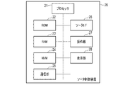
- FIG. 4 is a block diagram showing a configuration example of the sorter control device 20.
- the sorter control device 20 includes a processor 21, a ROM 22, a RAM 23, an NVM 24, a communication section 25, a sorter interface 26, an operation section 27, a display section 28, and the like.
- the processor 21, ROM 22, RAM 23, NVM 24, sorter interface 26, communication section 25, operation section 27 and display section 28 are connected to each other via a data bus or the like.
- the sorter control device 20 may have a configuration other than the configuration shown in FIG.
- the processor 21 has a function of controlling the operation of the entire sorter control device 20 .
- Processor 21 may include an internal cache, various interfaces, and the like.
- the processor 21 implements various processes by executing programs pre-stored in the internal memory, ROM 22 or NVM 24 .
- processor 21 controls the functions performed by the hardware circuits.
- the ROM 22 is a non-volatile memory in which control programs, control data, etc. are stored in advance.
- the control programs and control data stored in the ROM 22 are installed in advance according to the specifications of the sorter control device 20 .
- the RAM 23 is a volatile memory.
- the RAM 23 temporarily stores data being processed by the processor 21 .
- RAM 23 stores various application programs based on instructions from processor 21 .
- the RAM 23 may store data necessary for executing the application program, execution results of the application program, and the like.
- the NVM 24 is a non-volatile memory in which data can be written and rewritten.
- the NVM 24 is composed of, for example, an HDD, SSD, flash memory, or the like.
- the NVM 24 stores control programs, applications, various data, and the like according to the operational use of the sorter control device 20 .
- the communication unit 25 is an interface for communicating with the partitioning control device 10 and the like.
- the communication unit 25 is an interface for transmitting/receiving data to/from the partitioning control device 10 or the like via a network.
- the communication unit 25 is an interface that supports wired or wireless LAN connection.
- the sorter interface 26 is an interface for communicating with the sorter 5.
- the operation unit 27 receives inputs for various operations from the operator.
- the operation unit 27 transmits a signal indicating the input operation to the processor 21 .
- the operation unit 27 may be composed of a touch panel.
- the display unit 28 displays image data from the processor 21 .
- the display unit 28 is composed of a liquid crystal monitor.
- the display section 28 may be formed integrally with the operating section 27 .
- the communication unit 25 and the sorter interface 26 may be integrally formed.
- the processor 21 controls the sorter 5 according to control signals from the sorting control device 10 .
- processor 21 causes sorter 5 to sort predetermined articles into predetermined chutes.
- the processor 21 pushes the article into the chute at the timing when the article reaches the chute.
- FIG. 5 is a block diagram showing a configuration example of the AGV control device 30.
- the AGV control device 30 includes a processor 31, a ROM 32, a RAM 33, an NVM 34, a communication section 35, an AGV interface 36, an operation section 37, a display section 38, and the like.
- the processor 31, ROM 32, RAM 33, NVM 34, AGV interface 36, communication section 35, operation section 37 and display section 38 are connected to each other via a data bus or the like.
- the AGV control device 30 may have a configuration other than the configuration shown in FIG.
- the processor 31 has a function of controlling the operation of the AGV control device 30 as a whole.
- Processor 31 may include internal caches, various interfaces, and the like.
- the processor 31 implements various processes by executing programs pre-stored in the internal memory, ROM 32 or NVM 34 .
- processor 31 controls the functions performed by the hardware circuits.
- the ROM 32 is a non-volatile memory in which control programs, control data, etc. are stored in advance.
- the control programs and control data stored in the ROM 32 are preinstalled according to the specifications of the AGV control device 30 .
- the RAM 33 is a volatile memory.
- the RAM 33 temporarily stores data being processed by the processor 31 .
- RAM 33 stores various application programs based on instructions from processor 31 .
- the RAM 33 may store data necessary for executing the application program, execution results of the application program, and the like.
- the NVM 34 is a non-volatile memory in which data can be written and rewritten.
- the NVM 34 is composed of, for example, an HDD, SSD, flash memory, or the like.
- the NVM 34 stores control programs, applications, various data, etc. according to the operational use of the AGV control device 30 .
- the communication unit 35 is an interface for communicating with the partitioning control device 10 and the like.
- the communication unit 35 is an interface for transmitting/receiving data to/from the partitioning control device 10 or the like via a network.
- the communication unit 35 is an interface that supports wired or wireless LAN connection.
- the AGV interface 36 is an interface for communicating with the AGV7.
- AGV interface 36 wirelessly connects to AGV 7 .
- AGV interface 36 may support wireless LAN connectivity.
- the operation unit 37 receives inputs for various operations from the operator.
- the operation unit 37 transmits a signal indicating the input operation to the processor 31 .
- the operation unit 37 may be composed of a touch panel.
- the display unit 38 displays image data from the processor 31 .
- the display unit 38 is composed of a liquid crystal monitor.
- the display section 38 may be formed integrally with the operating section 37 .
- communication unit 35 and the AGV interface 36 may be integrally formed.
- the processor 31 controls the AGV 7 according to the control signal from the partition control device 10. For example, processor 31 causes AGV 7 to move to the receiving position. In addition, the processor 31 moves the AGV 7 to a position where the articles can be loaded into the first container 8 or the second container 9 with the articles loaded thereon. The processor 31 also causes the AGV 7 to load the first container 8 or the second container 9 with articles.
- FIG. 6 is a perspective view of the AGV7.
- FIG. 7 is a top view of AGV7.
- the AGV7 has a base 701.
- the base 701 functions as a moving mechanism for moving the cross belt 700, which will be described later.
- a sensor 77 is formed on the front surface of the base 701 . The sensor 77 will be described later.
- a member 702 extending upward is formed on the base 701 .
- a cross belt 700 is formed on the upper end of the member 702 .
- FIG. 8 is a side view of the cross belt 700.
- the cross belt 700 (loading mechanism) is formed from a belt-like belt that is formed in a ring shape. Rollers 703 are formed inside the cross belt 700 . Cross belt 700 is supported by rollers 703 while being pulled with a predetermined tension.
- the cross belt 700 is rotated by driving rollers 703 and the like.
- the cross belt 700 is composed of one belt.
- the cross belt 700 may be composed of two or more belts.
- FIG. 9 is a block diagram showing a configuration example of the AGV7.
- the AGV 7 includes a processor 71, a ROM 72, a RAM 73, an NVM 74, a communication section 75, a driving section 76, a sensor 77, a battery 78, a charging mechanism 79, tires 70, and the like.
- the AGV 7 may have a configuration other than the configuration shown in FIG. 9 as necessary, or a specific configuration may be excluded from the AGV 7.
- the processor 71 has the function of controlling the operation of the entire AGV7.
- Processor 71 may include internal caches, various interfaces, and the like.
- the processor 71 implements various processes by executing programs pre-stored in the internal memory, ROM 72 or NVM 74 .
- the processor 71 is a CPU (Central Processing Unit).
- the processor 71 may be realized by hardware such as LSI (Large Scale Integration), ASIC (Application Specific Integrated Circuit), or FPGA (Field-Programmable Gate Array).
- the ROM 72 is a non-temporary computer-readable storage medium and stores the above program.
- the ROM 72 also stores data or various set values used by the processor 71 in performing various processes.
- the RAM 73 is a memory used for reading and writing data.
- the RAM 73 is used as a so-called work area for storing data temporarily used when the processor 71 performs various processes.
- the NVM 74 is a non-temporary computer-readable storage medium, and may store the above program. In addition, the NVM 74 stores data used by the processor 71 to perform various processes, data generated by the processes performed by the processor 71, various setting values, and the like.
- the communication unit 75 is an interface that transmits and receives data to and from the AGV control device 30 through a wireless LAN access point or the like.
- communication unit 75 supports wireless LAN connection.
- the drive unit 76 is a motor or the like, and rotates or stops the motor based on a drive signal output from the processor 71 .
- the power of the motor is transmitted to the tires 70 that move the base 701 and is transmitted to the steering mechanism.
- the power from such a motor causes the AGV 7 to move to the target position.
- the power of the motor is transmitted to the roller 703 .
- the power from such a motor causes the cross belt 700 to rotate and load the articles into the first container 8 or the second container 9 .
- the driving section 76 may be composed of a motor for driving the tire 70 and a motor for driving the cross belt 700 .
- the sensor 77 is a plurality of reflective sensors. Each reflective sensor is attached to the perimeter of the AGV7. Each reflection sensor emits a laser beam, detects the time from when the laser beam is emitted until the laser beam is reflected by an object and returns, detects the distance to the object based on the detected time, and outputs a detection signal. is notified to the processor 71 .
- the processor 71 outputs a control signal for controlling travel of the AGV 7 based on the detection signal from the sensor 77 . For example, based on the detection signal from the sensor 77, the processor 71 outputs a control signal such as deceleration or stop to avoid collision with an object.
- a camera may be provided, and the camera may capture the surroundings and output the captured image to the processor 71 .
- the processor 71 analyzes the captured image and outputs a control signal such as deceleration or stop to avoid collision with the object.
- the battery 78 supplies necessary power to the drive unit 76 and the like.
- the charging mechanism 79 is a mechanism that connects the charging station and the battery 78 , and the battery 78 is charged with power supplied from the charging station or the like via the charging mechanism 79 .
- the processor 71 performs processing such as calculation and control necessary for operations such as acceleration, deceleration, stopping, direction change, and rotation of the cross belt 700 .
- the processor 71 executes a program stored in the ROM 72, the NVM 74, or the like based on control signals from the AGV control device 30 or the like, thereby generating drive signals and outputting them to each unit.
- the AGV controller 30 transmits a control signal to move the AGV 7 to the receiving position. Also, the AGV control device 30 transmits a control signal for moving the AGV 7 to the closing position. Also, the AGV control device 30 transmits a control signal for rotating the cross belt 700 .
- the processor 71 of the AGV 7 outputs a drive signal according to the control signal sent from the AGV control device 30. This causes the AGV 7 to move from the current position to the receiving position.
- the AGV 7 receives the articles from the sorter 5 at the receiving position, the AGV 7 moves to the loading position with the articles loaded.
- the AGV 7 loads the articles into the first container 8 or the second container 9 at the loading position.
- FIG. 10 shows an operation example in which the AGV 7 throws articles into the first container 8 or the second container 9.
- the AGV 7 rotates the cross belt 700 with articles loaded on the cross belt 700 .
- the AGV 7 puts the articles into the first container 8 or the second container 9 from one end of the cross belt 700 by rotating the cross belt 700 .
- the compartmentalization system 100 comprises either or both of two types of first containers 8 .
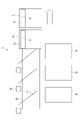
- FIG. 11 shows a cross-sectional view of a first container 8a as one type of first container 8.
- the first container 8a comprises an outer layer 81 .
- the outer layer 81 is formed in a rectangular parallelepiped shape.
- the outer layer 81 is hollow inside and has an open upper surface.
- the outer layer 81 may have a structure that further opens a portion of the side wall.
- the outer layer 81 is a basket or the like.
- a partition plate 82 is formed inside the outer layer 81 .
- a partition plate 82 divides the outer layer 81 into two regions. For example, one area receives articles from the sorter 5 . Also, an article is thrown into the other area from the AGV 7 .
- FIG. 11 shows a cross-sectional view of a first container 8b as the other kind of first container 8.
- the first container 8b comprises an outer layer 85.
- FIG. 11 shows a cross-sectional view of a first container 8b as the other kind of first container 8.
- the first container 8b comprises an outer layer 85.
- the outer layer 85 is formed in a rectangular parallelepiped shape.
- the outer layer 85 is hollow inside and has an open upper surface.
- the outer layer 85 may have a structure that further opens a portion of the side wall.
- the outer layer 85 is a basket or the like.
- the outer layer 85 may have the same structure as the outer layer 81.
- An oricon 87 is formed inside the outer layer 85 .
- the Oricon 87 is fixed to one side of the outer layer 85 by a folder 86 .
- Oricon 87 is formed in the shape of a rectangular parallelepiped.
- the oricon 87 is hollow inside and has an open upper surface.
- the Oricon 87 is a basket or a tray.
- Articles are put into the Oricon 87 from the sorter 5 . Also, an article is thrown into the outer layer 85 from the AGV 7 .
- FIG. 13 shows an installation example of the first container 8b.
- FIG. 13 is a sectional view of the sorter 5 and the first container 8b.
- sorter 5 conveys articles in a direction perpendicular to the drawing.
- the sorter 5 includes a plurality of trays 51 , a plurality of chutes 52 and a plurality of pushers 53 .
- a plurality of trays 51 are formed side by side in a direction perpendicular to the drawing. Each tray 51 loads articles. Tray 51 moves in a manner perpendicular to the drawing.
- a plurality of chutes 52 are formed side by side in a direction perpendicular to the drawing.
- the chute 52 is a conveying path through which the articles pushed out from the tray 51 pass.
- a chute 52 is formed downward from the tray 51 .
- the pusher 53 (throwing-in mechanism) pushes the articles loaded on the tray 51 to the chute 52 .
- the pusher 53 is pushed out toward the chute 52 by the operation of the drive section or the like. By pushing out the pusher 53 , the articles loaded on the tray 51 are pushed out to the chute 52 .
- the pusher 53 pushes the articles to a specific chute according to the sorting destination of the articles.
- the pusher 53 is positioned in the direction opposite to the direction in which the article is pushed out before the induction 4 places the article on the tray 51 .
- the first container 8b is installed at the end of the chute 52.
- the first container 8b is installed in an orientation in which the oricon 87 is formed on the chute 52 side. Thereby, the trough 87 of the first container 8b receives the articles passing through the chute 52. As shown in FIG.
- outer layer 85 the side surface facing the side surface on which the oricon 87 is formed is partially open. Outer layer 85 thereby receives an article from AGV 7 .
- FIG. 14 is a top view of the sorter 5.
- FIG. 15 is a side view of the sorter 5.
- a pusher 53 is formed at one end of the tray 51 .
- the pusher 53 is formed in a rectangular bar shape.
- the pusher 53 is formed to be movable in the direction orthogonal to the direction in which the pusher 53 extends in the tray 51 .
- a projecting portion 54 extending downward is formed on the pusher 53 .
- the protrusion 54 can move up and down.
- the projecting portion 54 is held upward by a spring or the like.
- a depression is formed in the lateral direction at the lower end of the protrusion 54 .
- a roller 55 is formed at the bottom of the tray 51 .
- the sorter 5 has rails 56 .
- the rail 56 is formed linearly in a predetermined direction.
- a roller 55 is loaded on the rail 56 .
- a guide 57 is formed for each chute 52 at the bottom of the rail 56 .
- the guide 57 is obliquely formed with respect to the direction in which the rail 56 extends.
- a guide 57 is fixed to the rail 56 .
- the guide 57 has a shape that meshes with the recess of the protrusion 54 .
- a solenoid 58 is formed at a position corresponding to the chute 52 across the rail 56 . Solenoid 58 pushes projecting portion 54 of 51 downward onto a passing tray.
- the tray 51 moves along the rail 56 in the direction of the arrow (rightward in FIGS. 14 and 15).
- the solenoid 58 pushes the projecting portion 54 of the tray 51 downward.
- the functions realized by the partitioning control device 10 are realized by the processor 11 executing a program stored in the internal memory, the ROM 12, the NVM 14, or the like.
- the processor 11 has a function of acquiring destination information.
- the sorting destination information indicates the sorting destination of the article.
- FIG. 16 shows a configuration example of the destination information.
- the classification destination information stores a record in which "ID" and "classification destination" are associated with each other.
- the "ID” is an identifier that identifies an article to be sorted.
- “ID” is a numerical value.
- the "classification destination” is the classification destination of the corresponding article. “Destination” corresponds to the first container 8 or the second container 9 (divided container). That is, the "sorting destination” is information that allows the processor 11 of the sorting control device 10 to specify the sorting container into which the articles are thrown. For example, “sort destination” is an identifier that specifies the first container 8 or the second container 9 . Also, the "classification destination” may be an address (or part of an address).
- the configuration of the classification destination information is not limited to a specific configuration.
- the processor 11 receives the classification destination information from the host device 6 through the communication unit 15 .
- the processor 11 may transmit a request for the sort destination information to the host device 6 through the communication unit 15 .
- the processor 11 also has a function of reading an ID from an article. Here, it is assumed that articles to be sorted are put into the throwing device 1 .
- the processor 11 supplies the articles from the input device 1 to the singulator 2 .
- the processor 11 uses the singulator 2 to arrange the articles in a predetermined direction.
- the processor 11 uses the scanner 3 to read IDs from articles arranged in a predetermined direction.
- the processor 11 may acquire the ID of the article from the scanner 3. Alternatively, the processor 11 may acquire an image from the scanner 3, decode a code appearing in the image, and acquire an ID.
- the processor 11 also has a function of specifying a classified container into which articles are put. After acquiring the ID of the article, the processor 11 refers to the sorting destination information and acquires the “sorting destination” corresponding to the acquired ID. After obtaining the "sorting destination", the processor 11 identifies the sorted container corresponding to the "sorting destination". That is, the processor 11 identifies one of the first containers 8 or one of the second containers 9 as the classified containers into which the articles are put.
- the processor 11 also has a function of putting articles into the specified classified container. 17 and 18 show an example of an operation in which the processor 11 puts articles into the classified containers.
- the chute 52 for throwing articles into the first container 8 is called a fixed section chute 52a.
- the chute 52 for loading articles on the AGV 7 is referred to as a grouping section chute 52b.
- the processor 11 uses the induction 4 to load the articles onto the tray 51 .
- the processor 11 may generate tracking information that identifies the tray 51 .
- the tracking information stores the ID of the article and the ID specifying the tray 51 in association with each other.
- the processor 11 identifies the chute 52 into which the articles are to be thrown according to the identified classified container.
- the processor 11 puts articles from the sorter 5 into the first bin 8, or uses the AGV 7 to fill the first bin 8. It is determined whether or not to put an article into the container 8 .
- the processor 11 determines whether to put the article into the first container 8 from the sorter 5 or put the article into the first container 8 using the AGV 7. .
- the processor 11 determines that the item should be put into the first container 8 using the AGV 7 . That is, the processor 11 separates relatively small and light articles from other articles and puts them into the first container 8 .
- the processor 11 When it is determined that the sorter 5 will put the articles into the first container 8 , the processor 11 identifies the fixed sectioned chute 52 a corresponding to the first container 8 . After specifying the fixed sorted chute 52a, the processor 11 transmits to the sorter control device 20 via the communication unit 15 a control signal for causing the sorter 5 to put the articles in the tray 51 into the fixed sorted chute 52a.
- the processor 21 of the sorter control device 20 throws the articles in the tray 51 into the fixed sorted chute 52a according to the control signal. For example, the processor 21 uses the pusher 53 to throw the article from the tray 51 into the fixed sectioned chute 52a at the timing when the tray 51 reaches the fixed sectioned chute 52a. Articles pass through the fixed sectioned chute 52a and are thrown into the first container 8. As shown in FIG.
- the pusher 53 pushes the articles to a specific chute according to the sorting destination of the articles.
- the pusher 53 is positioned in the direction opposite to the direction in which the article is pushed out before the induction 4 places the article on the tray 51 .
- the processor 11 when it is determined that the AGV 7 is used to put the articles into the first container 8, the processor 11 causes the AGV 7 to stand by at one of the collection sorting chutes 52b. For example, the processor 11 transmits a control signal to the AGV control device 30 through the communication unit 15 to move the AGV 7 to the receiving position corresponding to the grouping section chute 52b.
- the processor 31 of the AGV control device 30 moves one of the AGVs 7 to the receiving position according to the control signal.
- the processor 11 sends a control signal to the sorter control device 20 via the communication unit 15 to cause the sorter 5 to throw the articles in the tray 51 into the collection sorting chute 52b.
- the processor 21 of the sorter control device 20 puts the articles in the trays 51 into the collection sorting chute 52b according to the control signal. For example, the processor 21 uses the pusher 53 to throw the articles from the tray 51 into the collecting and dividing chute 52b at the timing when the tray 51 reaches the collecting and dividing chute 52b. The articles are loaded onto the AGV 7 after passing through the collecting section chute 52b.
- the processor 11 When the article is loaded onto the AGV 7 , the processor 11 sends a control signal to the AGV control device 30 to load the article into the first container 8 through the communication section 15 .
- the processor 31 of the AGV control device 30 moves the AGV 7 to the loading position of the first container 8 according to the control signal. When moved to the loading position, the processor 31 rotates the cross belt 700 of the AGV 7 to load the article into the first container 8 .
- the processor 11 of the sorting control device 10 sends a control signal to the AGV control device 30 to move the AGV 7 to one receiving position of the collecting sorting chute 52b. good.
- the processor 11 causes the AGV 7 to wait in one of the collective classified chutes 52b. For example, the processor 11 transmits a control signal to the AGV control device 30 through the communication unit 15 to move the AGV 7 to the receiving position corresponding to the grouping section chute 52b.
- the processor 31 of the AGV control device 30 moves one of the AGVs 7 to the receiving position according to the control signal.
- the processor 11 sends a control signal (a control signal for causing the sorter 5 to throw the articles into the AGV 7) to the sorter 5 through the communication unit 15 to throw the articles in the tray 51 into the collection sorting chute 52b. 20.
- the processor 21 of the sorter control device 20 puts the articles in the trays 51 into the collection sorting chute 52b according to the control signal. For example, the processor 21 uses the pusher 53 to throw the articles from the tray 51 into the collecting and dividing chute 52b at the timing when the tray 51 reaches the collecting and dividing chute 52b. The articles are loaded onto the AGV 7 after passing through the collecting section chute 52b.
- the processor 11 When the article is loaded onto the AGV 7 , the processor 11 sends a control signal to the AGV control device 30 to load the article into the first container 8 through the communication unit 15 .
- the processor 31 of the AGV control device 30 moves the AGV 7 to the insertion position of the second container 9 according to the control signal. When moved to the loading position, the processor 31 rotates the cross belt 700 of the AGV 7 to load the article into the second container 9 .
- the processor 11 of the sorting control device 10 sends a control signal to the AGV control device 30 to move the AGV 7 to one receiving position of the collecting sorting chute 52b. good.
- the processor 11 may cause the AGV 7 to wait at the end of the sorter 5 .
- the processor 11 determines whether to load the article onto the AGV 7 from the end based on the shape or weight of the article. For example, the processor 11 determines whether to load the AGV 7 from the end if the side length or weight exceeds a predetermined threshold.
- the predetermined threshold value is based on the shape or weight of the article that the pusher 53 can push.
- the processor 11 When determining whether to load the AGV 7 from the end, the processor 11 causes the AGV 7 to wait at the end of the sorter 5 .
- the sorter 5 loads the articles from the tray 51 onto the AGV 7 at the end.
- the processor 11 causes the AGV 7 to load the goods into the first container 8 or the second container 9 .
- the processor 11 repeats the above operation to sort the articles of each ID indicated by the sorting destination information into the first container 8 or the second container 9 .
- the processor 11 may determine whether the first container 8 is full after the first container 8 is filled with articles. When determining that the first container 8 is full, the processor 11 instructs the operator to replace the first container 8 through the display 17 .
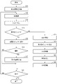
- FIG. 19 is a flowchart for explaining an operation example of the partitioning control device 10.
- the processor 11 of the partitioning control device 10 acquires partitioning destination information from the host device 6 through the communication unit 15 (S11). After acquiring the sorting destination information, the processor 11 uses the scanner 3 to read the ID from the thrown-in article (S12).
- the processor 11 After reading the ID from the item, the processor 11 uses the induction 4 to put the item into the tray 51 of the sorter 5 (S13). When the articles are put into the tray 51, the processor 11 determines whether the articles are put into the fixed sorted chute 52a (S14).
- the processor 11 When it is determined that the articles are to be thrown into the fixed sectioned chutes 52a (S14, YES), the processor 11 causes the sorter 5 to throw the articles into one of the fixed sectioned chutes 52a (S15).
- the processor 11 determines whether the first container 8 into which the articles have been put is full (S16). When determining that the first container 8 is full (S16, YES), the processor 11 instructs the worker to replace the first container 8 through the display unit 17 (S17).
- the processor 11 moves the AGV 7 to the receiving position of the empty collecting and sorting chute 52b (or the end of the sorter 5). Move (S18).
- the processor 11 causes the sorter 5 to put the articles into the collecting and sorting chute 52b (convey to the end) (S19).
- the processor 11 moves the AGV 7 to the throwing position of one of the first container 8 or the second container 9 (S20).
- the processor 11 When the AGV 7 is moved to the loading position, the processor 11 causes the AGV 7 to dump the cargo into the first container 8 or the second container 9 (S21). After the AGV 7 has loaded the cargo into the first container 8 or the second container 9, the processor 11 moves the AGV 7 to the receiving position of the vacant collection section chute 52b (S22).
- the processor 11 determines whether or not the article of each ID indicated by the sorting destination information has been sorted (S23).
- the processor 11 If it is determined that the sorting of the articles of each ID indicated by the sorting destination information has not been completed (S23, NO), the processor 11 returns to S12. When it is determined that the sorting of the articles of each ID indicated by the sorting destination information has been completed (S23, YES), the processor 11 ends the operation.
- processor 11 may cause the AGV 7 to wait in advance at the receiving position of the grouping section chute 52b.
- the fixed sectioned chute 52a and the collective sectioned chute 52b may be formed in a mixed manner.
- the sorter 5 may supply articles directly from the tray 51 to the first container 8 or the AGV 7 . That is, the sorter 5 does not have to have the chute 52 .
- the sorting system configured as described above uses the sorter to directly put the articles into the first container.
- the sorting system also loads the items from the sorter into the AGV and the AGV dumps the items into the second bin.
- the sorting system can automatically sort the articles using the AGV by increasing the number of second containers, even if the number of sorting destinations increases.
- the sorting system can quickly put the articles into the sorting destination by setting the sorting destination to which the articles are frequently thrown in as the first container.
- the sorting system determines whether to use the sorter or the AGV according to the shape or weight of the articles put into the first container. As a result, the sorting system can segregate items that differ in shape, weight, etc., into the first container. Thus, the sorting system can prevent damage to articles.
Landscapes
- Engineering & Computer Science (AREA)
- Business, Economics & Management (AREA)
- Mechanical Engineering (AREA)
- Economics (AREA)
- Operations Research (AREA)
- Tourism & Hospitality (AREA)
- Theoretical Computer Science (AREA)
- Entrepreneurship & Innovation (AREA)
- Human Resources & Organizations (AREA)
- Marketing (AREA)
- General Physics & Mathematics (AREA)
- Quality & Reliability (AREA)
- Strategic Management (AREA)
- Development Economics (AREA)
- Physics & Mathematics (AREA)
- General Business, Economics & Management (AREA)
- Accounting & Taxation (AREA)
- Finance (AREA)
- Warehouses Or Storage Devices (AREA)
- Discharge Of Articles From Conveyors (AREA)
- Control Of Position, Course, Altitude, Or Attitude Of Moving Bodies (AREA)
- Circuits Of Receivers In General (AREA)
Abstract
Description
実施形態に係る区分システムは、各物品を区分先に区分する。区分システムは、ソータ及び自動搬送車(Automated Guided Vehicle(AGV))を用いて、区分先に対応する容器に物品を投入する。区分システムは、物品をソータから直接、容器に投入する。また、区分システムは、物品をソータからAGVに載せ替えてAGVから容器に投入する。
プッシャーは、物品の区分先に応じて特定のシュートに物品を押し出す。プッシャーは、インダクション4がトレイに物品を載せる手前で、物品を押し出す方向の対向方向に位置させる。
第1の容器8については、後に詳述する。
ここでは、区分システム100は、複数の第1の容器8を備える。
AGV7については、後に詳述する。
図2は、区分システム100の制御系を示す。図2が示すように、区分システム100は、スキャナ3、インダクション4、ソータ5、上位装置6、AGV7、区分制御装置10、ソータ制御装置20及びAGV制御装置30などを備える。
たとえば、上位装置6は、WMS(Warehouse Management System)である。たとえば、上位装置6は、PCなどから構成される。
図3は、区分制御装置10の構成例を示すブロック図である。図3が示すように、区分制御装置10は、プロセッサ11、ROM12、RAM13、NVM14、通信部15、操作部16及び表示部17などを備える。
なお、区分制御装置10は、図3が示すような構成の他に必要に応じた構成を具備したり、区分制御装置10から特定の構成が除外されたりしてもよい。
図4は、ソータ制御装置20の構成例を示すブロック図である。図4が示すように、ソータ制御装置20は、プロセッサ21、ROM22、RAM23、NVM24、通信部25、ソータインターフェース26、操作部27及び表示部28などを備える。
なお、ソータ制御装置20は、図4が示すような構成の他に必要に応じた構成を具備したり、ソータ制御装置20から特定の構成が除外されたりしてもよい。
図5は、AGV制御装置30の構成例を示すブロック図である。図5が示すように、AGV制御装置30は、プロセッサ31、ROM32、RAM33、NVM34、通信部35、AGVインターフェース36、操作部37及び表示部38などを備える。
なお、AGV制御装置30は、図5が示すような構成の他に必要に応じた構成を具備したり、AGV制御装置30から特定の構成が除外されたりしてもよい。
図6は、AGV7の斜視図である。また、図7は、AGV7の上面図である。
図9は、AGV7の構成例を示すブロック図である。AGV7は、プロセッサ71、ROM72、RAM73、NVM74、通信部75、駆動部76、センサ77、バッテリー78、充電機構79、及びタイヤ70などを備える。
ここでは、区分システム100は、2種類の第1の容器8の何れか又は両方を備える。
仕切り板82は、外層81を2つの領域に区分けする。たとえば、一方の領域には、ソータ5から物品が投入される。また、他方の領域には、AGV7から物品が投入される。
図11は、他方の種類の第1の容器8としての第1の容器8bの断面図を示す。図11が示すように、第1の容器8bは、外層85を備える。
オリコン87は、フォルダ86によって外層85の一辺に固定されている。オリコン87は、直方体状に形成されている。オリコン87は、内部が空洞であり、上面を開放する。
たとえば、オリコン87は、カゴ又はトレイなどである。
図13は、第1の容器8bの設置例を示す。図13は、ソータ5及び第1の容器8bの断面図である。図13では、ソータ5は、図に対して垂直な方向に物品を搬送する。
トレイ51は、図に対して垂直な方向に並んで複数個形成されている。各トレイ51は、物品を積載する。トレイ51は、図に対して垂直な方法に移動する。
図14は、ソータ5の上面図である。また、図15は、ソータ5の側面図である。
前述の通り、区分先情報は、物品の区分先を示す。
「区分先」は、対応する物品の区分先である。「区分先」は、第1の容器8又は第2の容器9(区分容器)に対応する。即ち、「区分先」は、区分制御装置10のプロセッサ11が物品を投入する区分容器を特定することができる情報である。
たとえば、「区分先」は、第1の容器8又は第2の容器9を特定する識別子である。また、「区分先」は、住所(又は住所の一部)であってもよい。
ここでは、投入装置1には、区分の対象となる物品が投入されているものとする。
物品のIDを取得すると、プロセッサ11は、区分先情報を参照して、取得されたIDに対応する「区分先」を取得する。「区分先」を取得すると、プロセッサ11は、「区分先」に対応する区分容器を特定する。即ち、プロセッサ11は、物品を投入する区分容器として、第1の容器8の1つ、又は、第2の容器9の1つを特定する。
図17及び図18は、プロセッサ11が区分容器に物品を投入する動作例を示す。
図19は、区分制御装置10の動作例について説明するためのフローチャートである。
区分先情報が示す各IDの物品の区分を完了したと判定すると(S23、YES)、プロセッサ11は、動作を終了する。
また、ソータ5は、トレイ51から直接、第1の容器8又はAGV7に物品を供給するものであってもよい。即ち、ソータ5は、シュート52を備えなくともよい。
Claims (8)
- 情報処理装置と、ソータと、自動搬送車とを備えるシステムであって、
前記ソータは、
物品を積載するトレイと、
前記トレイから前記物品を第1の容器又は前記自動搬送車に投入する投入機構と、 を備え、
前記自動搬送車は、
前記物品を積載し第2の容器に前記物品を投入する積載機構と、
前記積載機構を移動させる移動機構と、
を備え、
前記情報処理装置は、
外部装置、前記ソータ及び前記自動搬送車と通信する通信部と、
前記通信部を通じて前記物品の区分先を示す区分先情報を前記外部装置から取得し、
前記区分先情報に基づいて、前記物品を投入する区分容器として前記第1の容器又は前記第2の容器を特定し、
前記第1の容器を特定した場合、前記通信部を通じて、前記ソータに前記物品を前記第1の容器へ投入させる制御信号を送信し、
前記第2の容器を特定した場合、前記通信部を通じて、前記ソータに前記物品を前記自動搬送車へ投入させる制御信号を送信し、前記通信部を通じて前記自動搬送車に前記物品を前記第2の容器へ投入させる制御信号を送信する、
プロセッサと、
を備える、
システム。 - 前記積載機構は、前記第1の容器に前記物品を投入し、
前記プロセッサは、前記第1の容器を特定した場合、前記物品の形状又は重量に基づいて、前記ソータに前記物品を前記自動搬送車へ投入させる制御信号を送信し、前記通信部を通じて前記自動搬送車に前記物品を前記第1の容器へ投入させる制御信号を送信する、請求項1に記載のシステム。 - 前記第1の容器は、外層と前記外層の内部に形成されるオリコンとを備え、
前記ソータは、前記オリコンに前記物品を投入し、
前記積載機構は、前記外層に前記物品を投入する、
請求項2に記載のシステム。 - 前記プロセッサは、前記第2の容器を特定した場合、前記通信部を通じて前記自動搬送車に前記ソータから前記物品を受領可能な位置へ移動させる制御信号を送信する、
請求項1乃至3の何れか1項に記載のシステム。 - 前記プロセッサは、前記自動搬送車が前記第2の容器に前記物品を投入した後に、前記通信部を通じて前記自動搬送車に前記ソータから前記物品を受領可能な位置へ移動させる制御信号を送信する、
請求項1乃至4の何れか1項に記載のシステム。 - 前記積載機構は、ベルトから構成され、前記物品が積載された状態で前記ベルトを回転させることで前記物品を前記第2の容器に投入する、
請求項1乃至5の何れか1項に記載のシステム。 - 前記物品のIDを読み取るスキャナを備え、
前記プロセッサは、前記ID及び前記区分先情報に基づいて、前記物品を投入する区分容器として前記第1の容器又は前記第2の容器を特定する、
請求項1乃至6の何れか1項に記載のシステム。 - プロセッサによって実行されるプログラムであって、
前記プロセッサに、
物品の区分先を示す区分先情報を取得する機能と、
前記区分先情報に基づいて、前記物品を投入する区分容器として第1の容器又は第2の容器を特定する機能と、
前記第1の容器を特定した場合、ソータに前記物品を前記第1の容器へ投入させる制御信号を送信する機能と、
前記第2の容器を特定した場合、前記ソータに前記物品を自動搬送車へ投入させる制御信号を送信し、前記自動搬送車に前記物品を前記第2の容器へ投入させる制御信号を送信する機能と、
を実現させるプログラム。
Priority Applications (4)
| Application Number | Priority Date | Filing Date | Title |
|---|---|---|---|
| EP22771077.9A EP4310024A4 (en) | 2021-03-18 | 2022-02-28 | SYSTEM AND PROGRAM |
| CA3210701A CA3210701A1 (en) | 2021-03-18 | 2022-02-28 | System and program |
| AU2022235846A AU2022235846A1 (en) | 2021-03-18 | 2022-02-28 | System and program |
| US18/461,903 US20230406629A1 (en) | 2021-03-18 | 2023-09-06 | System and computer-readable storage medium |
Applications Claiming Priority (2)
| Application Number | Priority Date | Filing Date | Title |
|---|---|---|---|
| JP2021044911A JP2022144067A (ja) | 2021-03-18 | 2021-03-18 | システム及びプログラム |
| JP2021-044911 | 2021-03-18 |
Related Child Applications (1)
| Application Number | Title | Priority Date | Filing Date |
|---|---|---|---|
| US18/461,903 Continuation US20230406629A1 (en) | 2021-03-18 | 2023-09-06 | System and computer-readable storage medium |
Publications (1)
| Publication Number | Publication Date |
|---|---|
| WO2022196323A1 true WO2022196323A1 (ja) | 2022-09-22 |
Family
ID=83321457
Family Applications (1)
| Application Number | Title | Priority Date | Filing Date |
|---|---|---|---|
| PCT/JP2022/008269 Ceased WO2022196323A1 (ja) | 2021-03-18 | 2022-02-28 | システム及びプログラム |
Country Status (6)
| Country | Link |
|---|---|
| US (1) | US20230406629A1 (ja) |
| EP (1) | EP4310024A4 (ja) |
| JP (1) | JP2022144067A (ja) |
| AU (1) | AU2022235846A1 (ja) |
| CA (1) | CA3210701A1 (ja) |
| WO (1) | WO2022196323A1 (ja) |
Families Citing this family (2)
| Publication number | Priority date | Publication date | Assignee | Title |
|---|---|---|---|---|
| JP2024085251A (ja) | 2022-12-14 | 2024-06-26 | 株式会社東芝 | 物品区分システム及び物品区分方法 |
| JP2024112209A (ja) * | 2023-02-07 | 2024-08-20 | 株式会社東芝 | 区分システム及び区分方法 |
Citations (2)
| Publication number | Priority date | Publication date | Assignee | Title |
|---|---|---|---|---|
| JP2020132330A (ja) | 2019-02-15 | 2020-08-31 | 株式会社東芝 | 物品管理装置、物品管理システム、及びプログラム |
| JP2020152461A (ja) * | 2019-03-18 | 2020-09-24 | 株式会社東芝 | 物品搬送制御装置、物品搬送制御システム、及びプログラム |
Family Cites Families (2)
| Publication number | Priority date | Publication date | Assignee | Title |
|---|---|---|---|---|
| US6892890B2 (en) * | 2001-01-16 | 2005-05-17 | Abb Automation, Inc. | Dynamic sortation of items in a containerization system |
| US20210031240A1 (en) * | 2019-07-29 | 2021-02-04 | Siemens Logistics Llc | Sorting system |
-
2021
- 2021-03-18 JP JP2021044911A patent/JP2022144067A/ja active Pending
-
2022
- 2022-02-28 CA CA3210701A patent/CA3210701A1/en active Pending
- 2022-02-28 WO PCT/JP2022/008269 patent/WO2022196323A1/ja not_active Ceased
- 2022-02-28 EP EP22771077.9A patent/EP4310024A4/en not_active Withdrawn
- 2022-02-28 AU AU2022235846A patent/AU2022235846A1/en not_active Abandoned
-
2023
- 2023-09-06 US US18/461,903 patent/US20230406629A1/en active Pending
Patent Citations (2)
| Publication number | Priority date | Publication date | Assignee | Title |
|---|---|---|---|---|
| JP2020132330A (ja) | 2019-02-15 | 2020-08-31 | 株式会社東芝 | 物品管理装置、物品管理システム、及びプログラム |
| JP2020152461A (ja) * | 2019-03-18 | 2020-09-24 | 株式会社東芝 | 物品搬送制御装置、物品搬送制御システム、及びプログラム |
Non-Patent Citations (1)
| Title |
|---|
| See also references of EP4310024A4 |
Also Published As
| Publication number | Publication date |
|---|---|
| EP4310024A4 (en) | 2025-01-22 |
| AU2022235846A1 (en) | 2023-09-21 |
| CA3210701A1 (en) | 2022-09-22 |
| US20230406629A1 (en) | 2023-12-21 |
| EP4310024A1 (en) | 2024-01-24 |
| JP2022144067A (ja) | 2022-10-03 |
Similar Documents
| Publication | Publication Date | Title |
|---|---|---|
| JP7510965B2 (ja) | アイテムを仕分ける方法 | |
| US12115559B2 (en) | Material handling apparatus and method for automatic and manual sorting of items using a dynamically configurable sorting array | |
| KR101863282B1 (ko) | 물품분류기용 다단 슈트장치, 그의 제어장치 및 제어방법 | |
| RU2739726C1 (ru) | Устройство организации изделий, система организации изделий и компьютерно-читаемый носитель хранения | |
| WO2022196323A1 (ja) | システム及びプログラム | |
| CA3060709A1 (en) | Material handling apparatus and method for automatic and manual sorting of items using a dynamically configurable sorting array | |
| KR20230123032A (ko) | 물품 자동 분류 컨베이어 시스템 | |
| JP7746082B2 (ja) | システム | |
| WO2024080328A1 (ja) | 投入装置及びシステム | |
| NZ787800A (en) | Material handling apparatus and method for sorting items using a dynamically configurable sorting array |
Legal Events
| Date | Code | Title | Description |
|---|---|---|---|
| 121 | Ep: the epo has been informed by wipo that ep was designated in this application |
Ref document number: 22771077 Country of ref document: EP Kind code of ref document: A1 |
|
| WWE | Wipo information: entry into national phase |
Ref document number: 3210701 Country of ref document: CA |
|
| WWE | Wipo information: entry into national phase |
Ref document number: 2022235846 Country of ref document: AU Ref document number: AU2022235846 Country of ref document: AU |
|
| ENP | Entry into the national phase |
Ref document number: 2022235846 Country of ref document: AU Date of ref document: 20220228 Kind code of ref document: A |
|
| WWE | Wipo information: entry into national phase |
Ref document number: 2022771077 Country of ref document: EP |
|
| NENP | Non-entry into the national phase |
Ref country code: DE |
|
| ENP | Entry into the national phase |
Ref document number: 2022771077 Country of ref document: EP Effective date: 20231018 |
|
| WWE | Wipo information: entry into national phase |
Ref document number: 11202306602V Country of ref document: SG |
|
| WWW | Wipo information: withdrawn in national office |
Ref document number: 2022771077 Country of ref document: EP |