WO2022196781A1 - 液体注入方法、液体注入装置および液体カートリッジ - Google Patents
液体注入方法、液体注入装置および液体カートリッジ Download PDFInfo
- Publication number
- WO2022196781A1 WO2022196781A1 PCT/JP2022/012450 JP2022012450W WO2022196781A1 WO 2022196781 A1 WO2022196781 A1 WO 2022196781A1 JP 2022012450 W JP2022012450 W JP 2022012450W WO 2022196781 A1 WO2022196781 A1 WO 2022196781A1
- Authority
- WO
- WIPO (PCT)
- Prior art keywords
- liquid
- channel
- ejection head
- flow path
- tip
- Prior art date
- Legal status (The legal status is an assumption and is not a legal conclusion. Google has not performed a legal analysis and makes no representation as to the accuracy of the status listed.)
- Ceased
Links
Images



Classifications
-
- B—PERFORMING OPERATIONS; TRANSPORTING
- B41—PRINTING; LINING MACHINES; TYPEWRITERS; STAMPS
- B41J—TYPEWRITERS; SELECTIVE PRINTING MECHANISMS, i.e. MECHANISMS PRINTING OTHERWISE THAN FROM A FORME; CORRECTION OF TYPOGRAPHICAL ERRORS
- B41J2/00—Typewriters or selective printing mechanisms characterised by the printing or marking process for which they are designed
- B41J2/005—Typewriters or selective printing mechanisms characterised by the printing or marking process for which they are designed characterised by bringing liquid or particles selectively into contact with a printing material
- B41J2/01—Ink jet
- B41J2/17—Ink jet characterised by ink handling
- B41J2/175—Ink supply systems ; Circuit parts therefor
- B41J2/17503—Ink cartridges
- B41J2/17553—Outer structure
-
- B—PERFORMING OPERATIONS; TRANSPORTING
- B41—PRINTING; LINING MACHINES; TYPEWRITERS; STAMPS
- B41J—TYPEWRITERS; SELECTIVE PRINTING MECHANISMS, i.e. MECHANISMS PRINTING OTHERWISE THAN FROM A FORME; CORRECTION OF TYPOGRAPHICAL ERRORS
- B41J2/00—Typewriters or selective printing mechanisms characterised by the printing or marking process for which they are designed
- B41J2/005—Typewriters or selective printing mechanisms characterised by the printing or marking process for which they are designed characterised by bringing liquid or particles selectively into contact with a printing material
- B41J2/01—Ink jet
- B41J2/17—Ink jet characterised by ink handling
- B41J2/175—Ink supply systems ; Circuit parts therefor
- B41J2/17503—Ink cartridges
- B41J2/1752—Mounting within the printer
- B41J2/17523—Ink connection
-
- B—PERFORMING OPERATIONS; TRANSPORTING
- B41—PRINTING; LINING MACHINES; TYPEWRITERS; STAMPS
- B41J—TYPEWRITERS; SELECTIVE PRINTING MECHANISMS, i.e. MECHANISMS PRINTING OTHERWISE THAN FROM A FORME; CORRECTION OF TYPOGRAPHICAL ERRORS
- B41J2/00—Typewriters or selective printing mechanisms characterised by the printing or marking process for which they are designed
- B41J2/005—Typewriters or selective printing mechanisms characterised by the printing or marking process for which they are designed characterised by bringing liquid or particles selectively into contact with a printing material
- B41J2/01—Ink jet
- B41J2/135—Nozzles
- B41J2/14—Structure thereof only for on-demand ink jet heads
-
- B—PERFORMING OPERATIONS; TRANSPORTING
- B41—PRINTING; LINING MACHINES; TYPEWRITERS; STAMPS
- B41J—TYPEWRITERS; SELECTIVE PRINTING MECHANISMS, i.e. MECHANISMS PRINTING OTHERWISE THAN FROM A FORME; CORRECTION OF TYPOGRAPHICAL ERRORS
- B41J2/00—Typewriters or selective printing mechanisms characterised by the printing or marking process for which they are designed
- B41J2/005—Typewriters or selective printing mechanisms characterised by the printing or marking process for which they are designed characterised by bringing liquid or particles selectively into contact with a printing material
- B41J2/01—Ink jet
- B41J2/17—Ink jet characterised by ink handling
- B41J2/175—Ink supply systems ; Circuit parts therefor
- B41J2/17503—Ink cartridges
- B41J2/17513—Inner structure
-
- B—PERFORMING OPERATIONS; TRANSPORTING
- B41—PRINTING; LINING MACHINES; TYPEWRITERS; STAMPS
- B41J—TYPEWRITERS; SELECTIVE PRINTING MECHANISMS, i.e. MECHANISMS PRINTING OTHERWISE THAN FROM A FORME; CORRECTION OF TYPOGRAPHICAL ERRORS
- B41J2/00—Typewriters or selective printing mechanisms characterised by the printing or marking process for which they are designed
- B41J2/005—Typewriters or selective printing mechanisms characterised by the printing or marking process for which they are designed characterised by bringing liquid or particles selectively into contact with a printing material
- B41J2/01—Ink jet
- B41J2/17—Ink jet characterised by ink handling
- B41J2/175—Ink supply systems ; Circuit parts therefor
- B41J2/17503—Ink cartridges
- B41J2/17526—Electrical contacts to the cartridge
- B41J2/1753—Details of contacts on the cartridge, e.g. protection of contacts
-
- B—PERFORMING OPERATIONS; TRANSPORTING
- B01—PHYSICAL OR CHEMICAL PROCESSES OR APPARATUS IN GENERAL
- B01L—CHEMICAL OR PHYSICAL LABORATORY APPARATUS FOR GENERAL USE
- B01L2200/00—Solutions for specific problems relating to chemical or physical laboratory apparatus
- B01L2200/02—Adapting objects or devices to another
- B01L2200/026—Fluid interfacing between devices or objects, e.g. connectors, inlet details
- B01L2200/027—Fluid interfacing between devices or objects, e.g. connectors, inlet details for microfluidic devices
-
- B—PERFORMING OPERATIONS; TRANSPORTING
- B41—PRINTING; LINING MACHINES; TYPEWRITERS; STAMPS
- B41J—TYPEWRITERS; SELECTIVE PRINTING MECHANISMS, i.e. MECHANISMS PRINTING OTHERWISE THAN FROM A FORME; CORRECTION OF TYPOGRAPHICAL ERRORS
- B41J2/00—Typewriters or selective printing mechanisms characterised by the printing or marking process for which they are designed
- B41J2/005—Typewriters or selective printing mechanisms characterised by the printing or marking process for which they are designed characterised by bringing liquid or particles selectively into contact with a printing material
- B41J2/01—Ink jet
- B41J2/135—Nozzles
- B41J2/14—Structure thereof only for on-demand ink jet heads
- B41J2002/14411—Groove in the nozzle plate
-
- C—CHEMISTRY; METALLURGY
- C12—BIOCHEMISTRY; BEER; SPIRITS; WINE; VINEGAR; MICROBIOLOGY; ENZYMOLOGY; MUTATION OR GENETIC ENGINEERING
- C12M—APPARATUS FOR ENZYMOLOGY OR MICROBIOLOGY; APPARATUS FOR CULTURING MICROORGANISMS FOR PRODUCING BIOMASS, FOR GROWING CELLS OR FOR OBTAINING FERMENTATION OR METABOLIC PRODUCTS, i.e. BIOREACTORS OR FERMENTERS
- C12M33/00—Means for introduction, transport, positioning, extraction, harvesting, peeling or sampling of biological material in or from the apparatus
- C12M33/04—Means for introduction, transport, positioning, extraction, harvesting, peeling or sampling of biological material in or from the apparatus by injection or suction, e.g. using pipettes, syringes, needles
Definitions
- the present invention relates to a liquid injection method, a liquid injection device and a liquid cartridge.
- Patent Literature 1 describes a method of uniformly injecting ink in a short period of time by injecting ink into an ink holding member housed in an ink tank by inserting an ink injection needle.
- Patent Document 1 it is necessary to separately guide the ink injected into the ink holding member to the ejection port by suction from the ejection port or the like. However, there is a problem that not a little ink is discharged from the ejection port by suctioning, and the ink is wasted.
- the present invention provides a liquid injection method, a liquid injection apparatus, and a liquid cartridge that can suppress wasteful consumption of liquid.
- the liquid injection method of the present invention comprises a liquid ejection head that ejects liquid, a flow path that is connected to the liquid ejection head and that can supply the liquid to the liquid ejection head, and a flow path that is connected to the flow path and is wider than the flow path.
- the present invention it is possible to provide a liquid injection method, a liquid injection apparatus, and a liquid cartridge capable of suppressing wasteful consumption of liquid.
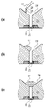
- FIG. 4 shows a liquid cartridge; It is the figure which showed a mode that the liquid was dripped to the opening part. It is a figure explaining the pinning effect of wetting. It is the figure which showed the injection method of the liquid by a micropipette.
- FIG. 4 is a diagram showing a channel into which a pipette tip of a micropipette is inserted; It is the figure which showed the liquid injection device.
- FIG. 10 is a diagram showing a state in which a pipette tip is inserted into a short channel;
- FIG. 1(a) is a perspective view showing the liquid cartridge 11 in this embodiment
- FIG. 1(b) is a cross-sectional view taken along line Ib-Ib in FIG. 1(a).
- c) is a partially enlarged view showing the liquid ejection head 21 of FIG. 1(b).
- the liquid cartridge 11 includes an opening 24 and a channel 23 provided between the opening 24 and the liquid ejection head 21 .
- the liquid ejection head 21 ejects liquid using the ejection principle of the inkjet method.
- the flow path 23 is configured to be able to supply the liquid to the liquid ejection head 21 and is narrowed in order to efficiently guide the liquid to the narrow common supply path 22 of the liquid ejection head 21 .
- the opening 24 is also capable of storing liquid, has a slope leading to the flow path 23 , and is formed so as to widen from the flow path 23 by the slope.
- the liquid supplied from the channel 23 to the liquid ejection head 21 is supplied to the ejection port 31 through the supply channel 22 of the liquid ejection head 21 .
- the liquid supplied to the ejection port 31 is ejected from the ejection port 31 by the action of the heating element 33 .
- the liquid ejection head 21 includes a silicon substrate 34, a heating element 33 provided thereon, an ejection port 31 formed by an ejection port forming material 35, and the like.
- a supply channel (hereinafter also referred to as a common supply channel) 22 and a channel 23 are attached so as to communicate with each other.
- a total of 320 discharge ports 31 are arranged on both sides of the supply channel 22 at predetermined intervals along the longitudinal direction.
- FIGS. 2(a) to 2(c) are diagrams showing how the liquid is dropped into the opening 24.
- FIG. In this case, a study was conducted to see if liquid could be dropped onto the slope of the opening 24 using a micropipette, which is a liquid injector, to fill the liquid ejection head 21 with the liquid.
- pure water 27 was used as a typical example of a liquid that is difficult to fill.
- pure water 27 was dropped onto the slope of the opening 24 using a pipette tip 25 of a micropipette. Thereafter, as shown in FIG.
- the pure water 27 is repelled by the wetting pinning effect at the angled portion at the connection between the opening 24 and the channel 23, and does not flow into the channel 23. rice field.
- a meniscus is formed at the connecting portion between the opening 24 and the channel 23, and the pure water 27 stays so as to block the channel 23, thereby discharging the liquid.
- the head 21 was never filled with pure water 27 .
- the liquid ejection head 21 cannot be filled with the liquid only by dropping the liquid.
- the head 21 could not be filled.
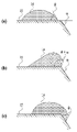
- FIG. 3 is a diagram explaining the pinning effect of wetting.
- the wetting pinning effect is a phenomenon in which when a droplet reaches a curved surface, it cannot proceed further until the contact angle ⁇ + ⁇ is equal to the contact angle ⁇ of the droplet plus the bending angle ⁇ . That is. Even if the bending angle ⁇ is rounded, it still makes it difficult for the droplet to advance.
- a droplet having a contact angle .theta. cannot pass over the curved surface until the contact angle becomes .theta.+.alpha. as shown in FIG. 3(b).
- the droplet advances over the curved surface as shown in FIG. 3(c).
- the pure water 27 passes through the flow path 23 as shown in FIG. 2(c) before passing over the curved portion. It clogs up and accumulates in the opening 24 .
- liquid is directly injected into the channel 23 with a micropipette in order to avoid clogging of the channel 23 due to such wetting pinning effect.
- FIG. 4 is a diagram showing a liquid injection method using a micropipette according to this embodiment.
- the pipette tip 25 of the micropipette has an inclined outer shape and is gradually tapered toward the tip.
- the liquid cartridge 11 also includes a channel 23 into which liquid can be directly injected.
- the pure water 27 was injected.
- the pure water 27 reached the common supply channel 22 of the liquid ejection head 21 from the channel 23 .
- the liquid ejection head 21 was filled with the pure water 27 due to the effect of capillary force and wettability.
- the amount of pure water 27 for filling the liquid ejection head 21 was sufficient at several tens of ⁇ l, and no pure water 27 wasted without being discharged from the ejection port 31 . Pure water 27 is generally considered difficult to fill because of its high surface tension. It is clear that the liquid ejection head 21 can be filled in the space.
- the pipette tip 25 of the micropipette is inserted into the channel 23 and the pure water 27 is injected.
- the liquid ejection head 21 can be filled with the pure water 27 without suction from the face surface 36 (see FIG. 1) of the liquid ejection head 21 or pressurization from the opening side.
- the tip of the pipette tip does not have to be inserted into the channel 23 .
- the tip 37 of the pipette tip 28 is arranged at substantially the same position as the connecting portion 30 between the opening 24 and the channel 23 in the direction of the arrow Z, and the droplet discharged from the pipette tip 28 is Alternatively, the liquid may be directly injected into the channel 23 without passing through the opening 24 .
- the size of the droplet discharged from the pipette tip 25 is controlled so that the diameter of the droplet is smaller than the width of the channel 23 .
- the liquid may be directly injected into the flow channel 23 without the injection.
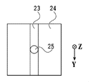
- FIG. 5 is a view of a state in which a pipette tip 25 of a micropipette is inserted into the channel 23, viewed from the opening 24 side.
- the channel 23 appears to be closed with the pipette tip 25 of the micropipette inserted into the channel 23 .
- the channel 23 is in the shape of a groove extending in the direction of the arrow Y, and even if the pipette chip 25 is inserted, the channel 23 will not be blocked.
- the channel 23 may be blocked by a micropipette on the opening 24 side. This is probably because the air existing in the channel 23 and the common supply channel 22 of the liquid ejection head 21 can gradually flow out from the ejection port 31 even if the channel 23 is blocked by the micropipette. However, from the viewpoint of smoother filling, it is preferable that a part of the channel 23 communicates with the atmosphere on the opening 24 side even when the pipette tip 25 is inserted into the channel 23 .
- the pure water 27 crosses the connecting portion between the flow path 23 and the opening 24 and is accumulated in the opening 24 .
- the pure water 27 crosses the connecting portion between the flow path 23 and the opening 24 and is accumulated in the opening 24 .
- the pure water 27 stored in the opening 24 flowed into the channel 23 without being pinned. It is considered that this is because the pure water 27 already existing in the channel 23 and the pure water 27 stored in the opening 24 are not separated as droplets but integrated as a bulk liquid.
- the contact angle to pure water is preferably 90° or more. A contact angle can be measured by a known method.
- the ejection port forming material 35 (see FIG. 1(c)) forming the ejection port 31 preferably has high wettability in order to naturally guide the liquid to the liquid ejection head 21 .
- the minute contact angle with respect to pure water on the surface of the ejection port forming member 35 is 40° or more and 90° or less. A minute contact angle can be measured by a known method.
- the liquid to be used may be not only pure water but also a coloring liquid such as black or color used for image formation.
- the liquid may be a resist, a metal nanoparticle solution, a carbon nanotube solution, an ultraviolet curing material, a functional polymer liquid, DNA, a cell fluid, or the like, and the liquids listed here are just examples and are not particularly limited. .
- the benefit of not wasting liquid is exhibited when the liquid is small, expensive, or when a poorly wettable liquid is used.
- a liquid containing at least one of cells, nucleic acids, proteins, labeling substances, hormones, and ribonucleotides used in the field of biotechnology is suitable as the liquid of this embodiment.
- Applications using cell suspensions as an example may involve handling liquid volumes as small as 100 ⁇ l or less.
- the liquid ejection head 21 can be filled with the liquid without performing suction from the face surface 36 or the like. Aseptic operation is important in the field of biotechnology, and one of the advantages is that there is no need to bring the suction member into contact with the face surface 36 and there is no risk of contamination.
- the liquid cartridge is preferably sterilized.
- Adhesive cells which have the property of adhering to the wall surface, are often used as the cell species. Adhesion to the wall surface can be suppressed by setting the range.
- the liquid injected into the flow path 23 is a liquid containing at least one of cells, nucleic acids, proteins, labeling substances, hormones, and ribonucleotides, from the viewpoint of dischargeability, it is Shorter times are preferred. Specifically, the time from the injection of the liquid into the flow path that can be supplied to the liquid ejection head to the ejection of the liquid from the ejection port of the liquid ejection head is preferably 10 minutes or less, and 5 minutes or less. is more preferable, and within 2 minutes is even more preferable.
- the inside of the liquid ejection head 21 When the inside of the liquid ejection head 21 is wet with liquid, it is preferable to remove the liquid by drying prior to injecting the liquid. This is because if the inside of the liquid ejection head 21 is wet with liquid, minute bubbles may be generated, which may make filling difficult. For example, when used in the field of biotechnology as described above, sterilization by heated steam may be performed, but such an operation tends to cause water to accumulate in the liquid ejection head. In such a case, it is preferable to dry the inside of the liquid ejection head 21 in advance before injecting the liquid into the channel. In addition, the liquid to be injected needs to be handled at a temperature lower than room temperature (25° C.) depending on the type of cells contained in the liquid.
- the liquid ejection head when the liquid ejection head is cooled from room temperature to the temperature of the injected liquid, dew condensation occurs inside the liquid ejection head, and as a result, the liquid may not be ejected properly. Therefore, it is preferable to inject the liquid into the liquid ejection head in an atmosphere with a dew point lower than the temperature of the cell suspension.
- the micropipette 104 directly injects the liquid into the channel 23 . Accordingly, it is possible to provide a liquid injection method, a liquid injection apparatus, and a liquid cartridge that can suppress wasteful consumption of liquid.
- Example 1 liquid was injected into the liquid cartridge using the following liquid, liquid cartridge, liquid injector, and liquid injection device. The injection of the liquid was performed with the liquid injection part inserted into the channel.
- the liquid used in this example is a cell suspension tinted with trypan blue.
- This liquid was prepared as follows.
- RAW264.7 a cell line established from mouse monocytic leukemia, was purchased from the American Type Culture Collection. Then, D-MEM (manufactured by Thermo Fisher Scientific) containing 10% FBS, 1% P / S (manufactured by Sigma-Aldrich), and 1% MEM-NEAA so that the cell line becomes 2 million cells / ml. ) dispersed in 20 ml of medium. After that, 2,000,000 seeds were seeded in a polystyrene 100 mm dish (manufactured by Corning).
- FBS is fetal bovine serum
- P/S penicillin-streptomycin
- MEM-NEAA MEM non-essential amino acids
- D-MEM Dulbecco's Modified Eagle Medium
- PBS is phosphate buffered saline
- EDTA ethylenediaminetetraacetic acid.
- 0.4 mass/volume % trypan blue solution were mixed at 9:1.
- the solution was added and stirred with a micropipette to obtain a liquid with a cell concentration of 1,000,000 cells/ml.
- the liquid cartridge 11 used in this embodiment is the one described with reference to FIGS. 1(a) to 1(c).
- the length of the channel 23 was 6 mm
- the width of the channel 23 was 1 mm
- the aspect ratio of the channel 23 (here, the ratio of length to width) was 6.
- the channel 23 and the opening 24 are made of polypropylene, and the contact angle of the pure water on the walls thereof was 105° when measured with a contact angle meter (manufactured by Kyowa Interface Science, DMo-701).
- the minute contact angle of the ejection port forming material 35 was 55° when measured with a minute contact angle meter (DropMeasure, manufactured by Microjet).
- the material was carefully cut out with a utility knife and measured on the side that comes into contact with the liquid, that is, the surface opposite to the face surface.
- liquid injector As a liquid injector, a micropipette 104 (manufactured by Eppendorf, Reference 2, 20-200 ⁇ L, yellow) equipped with a pipette tip (manufactured by Eppendorf, epTIPS.2-200 ⁇ L, biopur) was used.
- FIG. 6 is a diagram showing the liquid injection device 101 used in this embodiment.
- the liquid injection device 101 has a holding portion 105 of the liquid cartridge 11 and a holding portion 103 of the micropipette 104, and is provided with an adjustment mechanism capable of adjusting the relative positional relationship therebetween by means of a stage 102.
- FIG. 6 is a diagram showing the liquid injection device 101 used in this embodiment.
- the liquid injection device 101 has a holding portion 105 of the liquid cartridge 11 and a holding portion 103 of the micropipette 104, and is provided with an adjustment mechanism capable of adjusting the relative positional relationship therebetween by means of a stage 102.
- the outer diameter of the tip of the micropipette 104 is smaller than the width of the opening 24 , and the outer diameter of the tip is smaller than the width of the channel 23 .
- the liquid injection device 101 is a device that holds the liquid cartridge 11 and the micropipette 104 (liquid injector), and can control the relative positions of the liquid cartridge 11 and the micropipette 104 and the injection operation.
- the liquid injection device 101 may also have a liquid injector.
- a liquid injector 101 is equipped with a pre-dried liquid cartridge 11 and a micropipette 104 from which 50 ⁇ l of the liquid has been measured. inserted.
- the ejection button of the micropipette 104 was pressed to inject the liquid into the liquid cartridge 11 .
- the channel 23 was not blocked by the pipette chip 25 and communicated with the atmosphere on the opening 24 side, and the liquid ejection head 21 could be filled with the injected liquid.
- the liquid cartridge 11 was attached to a serial type inkjet recording apparatus (not shown), and 10 shots of the liquid were sequentially ejected from each ejection port onto paper.
- the time from liquid injection to discharge was 5 minutes. Since the liquid was colored with trypan blue, the ejection results could be determined visually.
- the liquid was ejected from all 320 ejection ports, and no ejection failure occurred. After that, 1000 shots were sequentially ejected from each ejection port, and the ejection was stable and no non-ejection occurred.
- Example 2 Evaluation was performed in the same manner as in Example 1, except that the channel 23 and the opening 24 were made of ABS resin.
- the contact angle of this ABS resin to pure water was 75°. No ejection failure occurred, but when the flow path 23 was observed after ejection, the wall surface of the flow path 23 was slightly wet with the liquid, and although a small amount of liquid remained on the wall surface, it was not at a problem level. rice field.
- Example 3 Evaluation was performed in the same manner as in Example 1, except that the minute contact angle of the outlet forming material 35 with respect to pure water was set to 25°. When 10 shots were sequentially ejected from each ejection port, ejection failure occurred in 30 ejection ports. It is believed that the cells adhered to the ejection port forming material 35 and clogged the ejection port 31 . No non-ejection occurred when the time from liquid injection to ejection was set to 2 minutes.
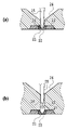
- FIG. 7(a) is a diagram showing a state in which the pipette tip 25 is inserted into the liquid cartridge 11 with the short channel 23.
- FIG. 7(a) is a diagram showing a state in which the pipette tip 25 is inserted into the liquid cartridge 11 with the short channel 23.
- the tip 26 of the pipette tip 25 comes into contact with the liquid ejection head 21 and damages the liquid ejection head 21, as shown in FIG. There is a risk of
- the tip 26 of the pipette tip 25 reaches the liquid ejection head 21 before the pipette tip 26 reaches the liquid ejection head 21.
- the taper portion of the tip 25 is configured to contact the inlet of the flow path 23 .
- the inclined contact surface contacts the inlet (contact portion) of the flow path 23 .
- the micropipette 104 or the liquid cartridge 11 has a mechanism for holding the pipette tip 25 (liquid injection part) in a state where it does not come into contact with the liquid ejection head 21 when it is inserted into the channel.
- the liquid injection device 101 may have it, but it is more preferable that the liquid cartridge 11 has it.
- Examples of the mechanism that the liquid cartridge 11 may have include a configuration in which a portion narrower than the pipette tip 25 is present in the flow channel so that the tip 26 of the pipette tip 25 does not reach the liquid ejection head 21, and a structure in which the flow channel 23 is There are curved configurations. Furthermore, there is a configuration in which the channel 23 is brought into contact with the tapered portion of the pipette tip 25 before the pipette tip 25 reaches the liquid ejection head 21 . In particular, it is preferable that the flow path 23 has an aspect ratio of 2 or more because many general-purpose pipette tips 25 do not contact the liquid ejection head 21, and an aspect ratio of 6 or more is more preferable.
- Example 4 Liquid injection was performed in the same manner as in Example 1, except that the length of the channel 23 was 1 mm, the width of the channel was 1 mm, and the aspect ratio of the channel was 1.
- the liquid ejection head 21 is filled with a liquid containing a compound and cells into which the compound is introduced.
- this liquid is called cell suspension (also called cell-containing liquid).
- the liquid ejection head 21 may also be called a cell processing liquid ejection head.
- the cell suspension ejected from the liquid ejection head 21 contains cells into which the compound has been introduced.
- a compound to be introduced into cells is appropriately referred to as a "compound to be introduced”.
- the compound to be introduced can be appropriately selected depending on the purpose.
- Compounds that can be introduced include, for example, nucleic acids, proteins, labeling substances, and the like. It should be noted that the compounds are not limited to these examples as long as they are of a size that can be included in the transfected cells. However, from the viewpoint of minimizing damage to cells, the size of the compound is preferably 1/5 or less, more preferably 1/10 or less of the average diameter of cells.
- Typical compounds applicable in this embodiment include nucleic acids such as DNA or RNA.
- Cells used in the present embodiment include adherent cells, planktonic cells, spheroids (aggregate cells), and the like.
- the average diameter of the cells is a size that allows ejection from the ejection port 31, and is, for example, 1 ⁇ m or more and 100 ⁇ m or less.
- the cell suspension contains at least one compound to be introduced and at least one cell to be introduced, and is mainly composed of water. Moreover, in the present invention, the cell suspension is obtained by dispersing cells in a liquid.
- the cells in the cell suspension may be in a state in which they can be dispersed in the liquid by stirring, and the cells may settle in the liquid when left standing.
- aqueous liquid medium containing water or a mixture of water and a water-soluble organic solvent
- a cell suspension can be obtained by adding cells and a compound to be introduced to an aqueous liquid medium.
- Compound introduction method In the compound introduction method of the present embodiment, cells cultured by adhesion culture, suspension culture, or the like are separated into individual cells or small clusters of cells by the action of an enzyme or the like, and then a centrifugal separator or the like is used. to sediment only the cells using the difference in specific gravity. Thereafter, after removing the supernatant medium other than the cells, a medium containing the compound to be introduced is added and stirred using a pipette or a stirrer to prepare a cell suspension.
- Large cell clumps are removed by passing the prepared cell suspension through a cell strainer having a minimum diameter equivalent to the minimum diameter of the flow path in the liquid ejection head 21 to be used.
- the cell suspension thus prepared is introduced into the liquid ejection head 21 using a micropipette or the like.
- the introduction operation is quickly performed as soon as the cell suspension is filled.
- the cell suspension is ejected from the ejection port 31 into the substrate or the culture solution.
- the compound to be introduced is introduced into the ejected cells.
Landscapes
- Automatic Analysis And Handling Materials Therefor (AREA)
Abstract
無駄な液体の消費を抑制することができる液体注入方法、液体注入装置および液体カートリッジを提供する。そのために、液体を吐出する液体吐出ヘッドと、前記液体吐出ヘッドと接続され前記液体吐出ヘッドに液体を供給可能な流路と、前記流路と接続され前記流路より広く設けられた開口部と、を備えた液体カートリッジに液体注入器から液体を注入する液体注入方法であって、液体を前記流路内に直接注入する。
Description
本発明は、液体注入方法、液体注入装置および液体カートリッジに関する。
特許文献1には、インクタンク内に収容されたインク保持部材に、インク注入針を刺してインク注入することで、均一に短時間でインクを注入する方法が記載されている。
特許文献1の方法では、インク保持部材に注入されたインクを、別途、吐出口からの吸引等で吐出口まで導く必要がある。しかし、吸引を行うことで、吐出口から少なからずインクが排出されてしまい、無駄にインクを消費するという課題があった。
よって本発明は、無駄な液体の消費を抑制することができる液体注入方法、液体注入装置および液体カートリッジを提供する。
そのため本発明の液体注入方法は、液体を吐出する液体吐出ヘッドと、前記液体吐出ヘッドと接続され前記液体吐出ヘッドに液体を供給可能な流路と、前記流路と接続され前記流路より広く設けられた開口部と、を備えた液体カートリッジに液体注入器から液体を注入する液体注入方法であって、液体を前記流路内に直接注入することを特徴とする。
本発明によれば、無駄な液体の消費を抑制することができる液体注入方法、液体注入装置および液体カートリッジを提供することができる。
本開示の更なる特徴は、添付の図面を参照して行う以下の実施形態の説明より明らかになる。
以下に、好ましい実施形態を挙げて、さらに本発明を説明するが、本発明は、以下の実施形態に限定されるものではない。なお、本明細書において物性値は、特に断りのない限り、常温(25℃)における値とする。
<<第1の実施形態>>
以下、図面を参照して本発明の第1の実施形態について説明する。
以下、図面を参照して本発明の第1の実施形態について説明する。
図1(a)は、本実施形態における液体カートリッジ11を示した斜視図であり、図1(b)は、図1(a)のIb-Ibにおける断面を示した図であり、図1(c)は、図1(b)の液体吐出ヘッド21を示した部分拡大図である。液体カートリッジ11は、開口部24と、開口部24と液体吐出ヘッド21との間に設けられた流路23とを備えている。液体吐出ヘッド21は、インクジェット方式の吐出原理を用いて液体を吐出する。流路23は、液体吐出ヘッド21に液体を供給可能に構成されており、液体吐出ヘッド21の細い共通供給路22に液体を効率的に導くために細くなっている。開口部24は、液体を貯留することも可能であり、流路23へとつながる斜面を備え、斜面により流路23から広がるように形成されている。流路23から液体吐出ヘッド21へ供給された液体は、液体吐出ヘッド21の供給流路22を経て吐出口31に供給される。吐出口31に供給された液体は、加熱素子33の作用によって吐出口31から吐出される。
液体吐出ヘッド21は、シリコン基板34とそこに設けられた加熱素子33、吐出口形成材35によって形成された吐出口31などを備えている。また供給流路(以下、共通供給路とも称する)22と流路23とは連通するように取り付けられている。吐出口31は、供給流路22の両側に計320個、長手方向に沿って所定の間隔で配されている。
図2(a)から(c)は、開口部24へ液体を滴下する様子を示した図である。ここでは、液体注入器であるマイクロピペットを用いて開口部24の斜面に液体を滴下して、液体吐出ヘッド21に液体を充填させることができるか検討を行った。ここでは、充填が困難な液体の代表例として純水27を用いて検討を行った。図2(a)のように開口部24の斜面にマイクロピペットのピペットチップ25を用いて純水27を滴下した。その後、純水27は、図2(b)のように、開口部24と流路23の接続部における角度がついている部分で、濡れのピン止め効果によってはじかれ、流路23に流入しなかった。さらに滴下を続けていくと、図2(c)のように、開口部24と流路23との接続部でメニスカスを形成して、流路23を塞ぐように純水27が留まり、液体吐出ヘッド21が純水27で充填されることはなかった。
つまり、開口部24の斜面に液体を滴下する場合には、滴下しただけでは液体吐出ヘッド21に液体を充填させることはできず、液体吐出ヘッド21側からの吸引等を行わなければ、液体吐出ヘッド21を充填させることはできなかった。
図3は、濡れのピン止め効果を説明する図である。濡れのピン止め効果とは、液滴が屈曲部のある表面に差しかかると、液滴の接触角θに屈曲角αを付け加えた分だけの接触角θ+αになるまでその先に進めなくなる現象のことである。屈曲角αは仮に丸みが付けられていても液滴が進みにくくなることには変わりがない。図3(a)のように、接触角θを有する液滴は、図3(b)のように、接触角θ+αになるまで屈曲部のある表面を超えられずその場に留まる。接触角θ+αになると、液滴は、図3(c)のように屈曲部のある表面を越えて進む。しかし、図2(b)のように、屈曲部のある表面を越えて進む先が細くなっている場合、純水27が屈曲部を超える前に図2(c)のように流路23を塞いでしまい開口部24に溜まる。
そこで本実施形態では、このような濡れのピン止め効果による流路23の閉塞を回避すべく、マイクロピペットで液体を流路23内に直接注入する。
図4は、本実施形態のマイクロピペットによる液体の注入方法を示した図である。マイクロピペットのピペットチップ25は、外形が傾斜しつつ先端に向かうに従い漸次細くなっている。また、液体カートリッジ11は、液体を直接注入可能な流路23を備えており、本実施形態では、図4のように、流路23内に直接、ピペットチップ25(液体注入部)の先端26を差し込み、純水27を注入した。その結果、純水27は、流路23から液体吐出ヘッド21の共通供給路22に到達した。共通供給路22に純水27が到達すると、毛管力による作用および濡れ性から液体吐出ヘッド21は純水27で充填された。
液体吐出ヘッド21を充填するための純水27の量は、数十μlで十分であり、吐出口31から排出されず、無駄になった純水27は無かった。純水27は、表面張力が高いため一般的に充填が難しいとされるが、本実施形態の方法では純水27が容易に充填されることから、純水27より表面張力の低い液体でも同様に液体吐出ヘッド21を充填できることは明らかである。
このように、流路23内にマイクロピペットのピペットチップ25を差し込んで純水27を注入する。これによって、液体吐出ヘッド21のフェイス面36(図1参照)からの吸引や開口部側からの加圧を行わなくても、液体吐出ヘッド21を純水27で充填することができる。
なお、ピペットチップの先端は、流路23に差し込まれていなくてもよい。ピペットチップ28のように、ピペットチップ28の先端37を、開口部24と流路23との接続部30と、矢印Z方向において略同一位置に配置し、ピペットチップ28から排出された液滴が、開口部24を介さずに流路23に直接注入される構成でもよい。
また、ピペットチップ25から排出される液滴の大きさを制御し、流路23の幅よりも小さな径の液滴とし、ピペットチップ29のように、流路23の上部から開口部24を介さずに、直接、流路23に液体を注入してもよい。
図5は、流路23にマイクロピペットのピペットチップ25を差し込んだ状態を、開口部24側から見た図である。図4では、流路23にマイクロピペットのピペットチップ25が差し込まれた状態で、流路23は塞がれているように見える。しかし流路23は、図5に示すように、矢印Y方向に延在した溝状になっており、ピペットチップ25が差し込まれても、流路23が塞がれることはない。そのため流路23に純水27が注入される際、ピペットチップ25が差し込まれても、流路23内にあった空気は、流路23のピペットチップ25が差し込まれていない連通部から開口部24側に流出することができる。
なお、流路23が開口部24側でマイクロピペットによって閉塞されていてもよい。流路23がマイクロピペットによって閉塞されていたとしても、流路23や液体吐出ヘッド21の共通供給路22内に存在する空気は吐出口31から徐々に流出できるためであると考えられる。しかし、よりスムーズに充填する観点から、流路23にピペットチップ25が差し込まれた状態においても、流路23の一部が開口部24側で大気と連通していることが好ましい。
液体吐出ヘッド21に純水27が充填された後、さらに注入を続けていくと、純水27は流路23と開口部24との接続部を越えて、開口部24に貯留される状態となる。この状態からピペットチップ25を流路23に差し込んだままで純水27を抜き取っていくと、開口部24に貯留された純水27はピン止めされずに流路23に流れ込んだ。これは流路23に既に存在する純水27と開口部24に貯留された純水27とが、液滴として分離しているわけではなくバルクの液体として一体であるためであると考えられる。
また、流路23や開口部24の壁面は、濡れ性を下げると壁面に付着する形で残る液体の量が減るため好ましく、流路23及び開口部24の壁面のうちの少なくとも一方の壁面の、純水に対する接触角が90°以上であると好ましい。接触角の測定は公知の方法で行うことができる。
吐出口31を形成する吐出口形成材35(図1(c)参照)は、液体吐出ヘッド21に自然に液体を導くために濡れ性が高いことが好ましい。しかし濡れ性が高すぎると液体内の成分が吸着したり、つまりを引き起こしたりすることがある。そのため吐出口形成材35の表面における純水に対する微小接触角が40°以上90°以下であることが好ましい。微小接触角の測定は公知の方法で行うことができる。
上記の説明では、流路23に注入される液体として純水を挙げたが、用いる液体としては、純水以外にも画像形成に用いられるブラックやカラーなどの着色用の液体であってもよい。更に液体は、レジスト、金属ナノ粒子溶液、カーボンナノチューブ溶液、紫外線硬化材料、機能性高分子液、DNA、細胞液などであってもよく、ここに挙げた液体はあくまで一例であって特に限定されない。液体を無駄にしないという有益性は、液体が少量である場合や高価である場合、また濡れ性が悪い液体を使用する場合により発揮される。
例えばバイオテクノロジーの分野で使われる、細胞、核酸、タンパク質、標識物質、ホルモン、およびリボヌクレオチドのうちの少なくとも1つを含んだ液体は、本実施形態の液体として好適である。一例として細胞懸濁液を使用した用途では、100μl以下の少量の液体を扱う場合がある。このような少量であっても本実施形態を適用することで、フェイス面36からの吸引などを行うことなく液体吐出ヘッド21へ液体を充填することができる。バイオテクノロジーの分野では無菌操作を行うことが大切になるが、フェイス面36に吸引部材を接触する必要がなくコンタミのリスクがないことも優位性の一つである。また、液体カートリッジは滅菌されていることが好ましい。また細胞種としては、壁面に接着する性質を持つ接着細胞を用いることも多いが、流路23や開口部24、吐出口形成材35の濡れ性(接触角や微小接触角)を上記の好ましい範囲にしておくことで、壁面への接着を抑制することができる。また、流路23に注入される液体が、細胞、核酸、タンパク質、標識物質、ホルモン、およびリボヌクレオチドのうちの少なくとも1つを含んだ液体の場合、吐出性の観点から、注入から吐出までの時間は短い方が好ましい。具体的には、液体吐出ヘッドに供給可能な流路への液体の注入から液体吐出ヘッドの吐出口からの液体の吐出までの時間は、10分以内であることが好ましく、5分以内であることがより好ましく、2分以内であることが更に好ましい。
液体吐出ヘッド21内が、液体で濡れている場合、液体の注入に先立って乾燥するなど液体を除去しておくことが好ましい。これは、液体吐出ヘッド21内が液体で濡れていると、微小な泡が発生していることがあり、充填がしにくくなる場合があるためである。例えば上記のようにバイオテクノロジー分野で使用する場合に、加熱水蒸気による滅菌を行うことがあるが、このような操作を行うと液体吐出ヘッド内に水が溜まりやすくなる。そのような場合は、流路内に液体を注入する前に液体吐出ヘッド21内を予め乾燥させておくことが好ましい。また、注入される液体は、その液体に含まれる細胞などの種類によっては室温(25℃)よりも低温で扱う必要がある。しかしながら、液体吐出ヘッドが室温から注入される液体の温度まで冷却された場合、液体吐出ヘッドの内部に結露が生じ、その結果、液体がうまく吐出できない場合がある。そのため、液体吐出ヘッドに液体の注入は、細胞懸濁液の温度より低い露点の雰囲気下で行われることが好ましい。
このように、マイクロピペット104で液体を流路23内に直接注入する。これによって、無駄な液体の消費を抑制することができる液体注入方法、液体注入装置および液体カートリッジを提供することができる。
<実施例>
以下に実施例および比較例を挙げて具体的に説明する。尚、その要旨を超えない限り、下記の実施例によって何ら限定されるものではない。なお、以下の記載における「%」は、特に断らない限り体積基準である。
以下に実施例および比較例を挙げて具体的に説明する。尚、その要旨を超えない限り、下記の実施例によって何ら限定されるものではない。なお、以下の記載における「%」は、特に断らない限り体積基準である。
<実施例1>
本実施例では以下のような液体、液体カートリッジ、液体注入器、液体注入装置を用いて、液体カートリッジへの液体の注入を行った。液体の注入は、液体注入部を流路に差し込んだ状態で行った。
本実施例では以下のような液体、液体カートリッジ、液体注入器、液体注入装置を用いて、液体カートリッジへの液体の注入を行った。液体の注入は、液体注入部を流路に差し込んだ状態で行った。
(液体)
本実施例で用いた液体は、トリパンブルーで薄く色を付けた細胞懸濁液である。この液体は以下のように調製した。American Type Culture Collectionよりマウス単球性白血病から樹立された細胞株であるRAW264.7を購入した。そしてその細胞株が200万個/mlになるように、10%FBS、1%P/S(シグマ アルドリッチ社製)、および1%MEM-NEAAを含むD-MEM(サーモフィッシャーサイエンティフィック社製)培地20ml中に分散させた。その後、ポリスチレン製100mmディッシュ(コーニング社製)に200万個ずつ播種した。5%CO2存在下摂氏37度でインキュベーションすることで細胞を増殖させた。2~4日後にディッシュ底面の面積の70%程度を細胞が覆った状態になったことを確認した。その後、上澄みの培地を除去した。そして、PBSでリンスした後、0.25%のトリプシンと、1mM EDTA(サーモフィッシャーサイエンティフィック社製)と、を含むPBSを用いて、細胞をディッシュより剥離させた。その後、マクロファージをディッシュから回収した。なお、FBSはウシ胎児血清、P/Sはペニシリン-ストレプトマイシン、MEM-NEAAはMEM非必須アミノ酸、D-MEMはDulbecco‘s Modified Eagle Medium、PBSはリン酸緩衝生理食塩水、EDTAはエチレンジアミン四酢酸を意味する。
本実施例で用いた液体は、トリパンブルーで薄く色を付けた細胞懸濁液である。この液体は以下のように調製した。American Type Culture Collectionよりマウス単球性白血病から樹立された細胞株であるRAW264.7を購入した。そしてその細胞株が200万個/mlになるように、10%FBS、1%P/S(シグマ アルドリッチ社製)、および1%MEM-NEAAを含むD-MEM(サーモフィッシャーサイエンティフィック社製)培地20ml中に分散させた。その後、ポリスチレン製100mmディッシュ(コーニング社製)に200万個ずつ播種した。5%CO2存在下摂氏37度でインキュベーションすることで細胞を増殖させた。2~4日後にディッシュ底面の面積の70%程度を細胞が覆った状態になったことを確認した。その後、上澄みの培地を除去した。そして、PBSでリンスした後、0.25%のトリプシンと、1mM EDTA(サーモフィッシャーサイエンティフィック社製)と、を含むPBSを用いて、細胞をディッシュより剥離させた。その後、マクロファージをディッシュから回収した。なお、FBSはウシ胎児血清、P/Sはペニシリン-ストレプトマイシン、MEM-NEAAはMEM非必須アミノ酸、D-MEMはDulbecco‘s Modified Eagle Medium、PBSはリン酸緩衝生理食塩水、EDTAはエチレンジアミン四酢酸を意味する。
回収した細胞懸濁液に、滅菌された遠心管内へ、総量50mlになるように、上記培地を加え後、4℃、90Gに設定した遠心分離機(日立社製、CF16RX II)で5分処理し、細胞を沈降させた。沈降した細胞ペレットの上澄みを、静かに除去し後、該細胞ペレットを、上記培地を加え、細胞懸濁液を得た。この懸濁液を再び、上記操作に従い、培養を2回繰り返した。
3回目の操作時では、必要な細胞数を別の遠心管へと取り分けて遠心分離し、沈降した細胞ペレットの上澄みを静かに除去した。その後、1倍のリン酸生理食塩緩衝液(1×PBS)(サーモフィッシャーサイエンティフィック社製、pH=7.4)と0.4質量/体積%のトリパンブルー溶液を9:1で混合した溶液を加えて、マイクロピペットで撹拌し細胞濃度100万個/mlの液体を得た。
(液体カートリッジ)
本実施例で用いた液体カートリッジ11は、図1(a)から(c)で説明したものを用いた。流路23の長さは6mm、流路23の幅は1mmであり、流路23における縦横比(ここでは長さと幅の比)であるアスペクト比は6であった。流路23と開口部24とはポリプロピレン製であり、その壁面における純水に対する接触角は、接触角計(協和界面科学製、DMo-701)で測定したところ105°であった。また、吐出口形成材35の微小接触角は、微小接触角計(マイクロジェット製、DropMeasure)で測定したところ55°であった。なお吐出口形成材35における微小接触角を測定する際には、カッターナイフで注意深く切り出して、液体が触れる側、すなわちフェイス面と逆の面で測定を行った。
本実施例で用いた液体カートリッジ11は、図1(a)から(c)で説明したものを用いた。流路23の長さは6mm、流路23の幅は1mmであり、流路23における縦横比(ここでは長さと幅の比)であるアスペクト比は6であった。流路23と開口部24とはポリプロピレン製であり、その壁面における純水に対する接触角は、接触角計(協和界面科学製、DMo-701)で測定したところ105°であった。また、吐出口形成材35の微小接触角は、微小接触角計(マイクロジェット製、DropMeasure)で測定したところ55°であった。なお吐出口形成材35における微小接触角を測定する際には、カッターナイフで注意深く切り出して、液体が触れる側、すなわちフェイス面と逆の面で測定を行った。
(液体注入器)
液体注入器としては、ピペットチップ(エッペンドルフ製、epT.I.P.S.2-200μL、biopur)を装着したマイクロピペット104(エッペンドルフ製、Reference2、20-200μL、黄色)を用いた。
液体注入器としては、ピペットチップ(エッペンドルフ製、epT.I.P.S.2-200μL、biopur)を装着したマイクロピペット104(エッペンドルフ製、Reference2、20-200μL、黄色)を用いた。
(液体注入装置)
図6は、本実施例で用いた液体注入装置101を示した図である。液体注入装置101は、液体カートリッジ11の保持部105と、マイクロピペット104の保持部103とを有し、その相対的な位置関係をステージ102で調整できる調整機構を備えている。
図6は、本実施例で用いた液体注入装置101を示した図である。液体注入装置101は、液体カートリッジ11の保持部105と、マイクロピペット104の保持部103とを有し、その相対的な位置関係をステージ102で調整できる調整機構を備えている。
マイクロピペット104は、先端の外径が開口部24の幅よりも小さく、更に先端の外径が流路23の幅よりも小さく構成されている。
液体注入装置101は、液体カートリッジ11とマイクロピペット104(液体注入器)とを保持する装置であり、液体カートリッジ11とマイクロピペット104との相対位置の制御や注入操作の制御を行い得る。また液体注入装置101は、液体注入器を有していてもよい。
本実施例では、液体注入装置101に、予め乾燥した液体カートリッジ11と、液体を50μl計り取ったマイクロピペット104とを装着し、ステージ102を動かして流路23内にマイクロピペット104のピペットチップ25を差し込んだ。
流路23にピペットチップ25を差し込んだ状態で、マイクロピペット104の排出ボタンを押して、液体カートリッジ11に液体を注入した。このとき流路23は、ピペットチップ25で塞がれておらず、開口部24側で大気と連通しており、注入した液体で液体吐出ヘッド21を充填することができた。
(評価)
液体カートリッジ11を、不図示のシリアル型のインクジェット記録装置に取り付け、紙上に各吐出口から順次10発ずつ液体を吐出した。液体注入から吐出までの時間は5分であった。液体はトリパンブルーで着色されているため、その吐出結果を目視で判断することができ、320個の全ての吐出口から液体が吐出されており、不吐出の発生はなかった。またその後、各吐出口から順次1000発ずつ吐出したが、吐出は安定しており不吐出の発生はなかった。
液体カートリッジ11を、不図示のシリアル型のインクジェット記録装置に取り付け、紙上に各吐出口から順次10発ずつ液体を吐出した。液体注入から吐出までの時間は5分であった。液体はトリパンブルーで着色されているため、その吐出結果を目視で判断することができ、320個の全ての吐出口から液体が吐出されており、不吐出の発生はなかった。またその後、各吐出口から順次1000発ずつ吐出したが、吐出は安定しており不吐出の発生はなかった。
吐出後に流路23を観察すると流路23の壁面は濡れておらず、壁面に付着して無駄になる液体もなかった。
<比較例1>
液体の注入において、ピペットチップ25を流路23に差し込まず、開口部24の壁面に液体を滴下して行う以外は、実施例1と同様の方法で行った。その結果、各吐出口31から順次10発ずつ吐出させる動作を行ったが、その全てが不吐出であった。またその後、各吐出口31から順次1000発ずつ吐出させる動作を行ったが、全て吐出口において不吐出が発生した。
液体の注入において、ピペットチップ25を流路23に差し込まず、開口部24の壁面に液体を滴下して行う以外は、実施例1と同様の方法で行った。その結果、各吐出口31から順次10発ずつ吐出させる動作を行ったが、その全てが不吐出であった。またその後、各吐出口31から順次1000発ずつ吐出させる動作を行ったが、全て吐出口において不吐出が発生した。
<比較例2>
200μlの液体を比較例1と同様に開口部24の壁面に滴下した。そして、液体吐出ヘッド21のフェイス面からアスピレータで吸引して、液体吐出ヘッド21に強制的に液体を充填させた。これら以外は比較例1と同様の方法で液体の注入を行った。その結果、各吐出口から順次10発ずつ吐出すると、320個の吐出口全てから吐出されており、不吐出の発生はなかった。しかし、アスピレータに吸引された液体の量を測定すると100μlであり、アスピレータに吸引された分が無駄になってしまった。
200μlの液体を比較例1と同様に開口部24の壁面に滴下した。そして、液体吐出ヘッド21のフェイス面からアスピレータで吸引して、液体吐出ヘッド21に強制的に液体を充填させた。これら以外は比較例1と同様の方法で液体の注入を行った。その結果、各吐出口から順次10発ずつ吐出すると、320個の吐出口全てから吐出されており、不吐出の発生はなかった。しかし、アスピレータに吸引された液体の量を測定すると100μlであり、アスピレータに吸引された分が無駄になってしまった。
<実施例2>
流路23と開口部24とをABS樹脂で形成した以外は、実施例1と同様の方法で評価を行った。このABS樹脂の純水に対する接触角は75°であった。不吐出の発生はなかったが、吐出後に流路23を観察すると、流路23の壁面はわずかに液体によって濡れており、壁面に液体がわずかに残ったが、問題となるレベルのものではなかった。
流路23と開口部24とをABS樹脂で形成した以外は、実施例1と同様の方法で評価を行った。このABS樹脂の純水に対する接触角は75°であった。不吐出の発生はなかったが、吐出後に流路23を観察すると、流路23の壁面はわずかに液体によって濡れており、壁面に液体がわずかに残ったが、問題となるレベルのものではなかった。
<実施例3>
吐出口形成材35の純水に対する微小接触角を25°とした以外は、実施例1と同様の方法で評価を行った。各吐出口から順次10発ずつ吐出しところ、30個の吐出口で不吐出が生じた。細胞が吐出口形成材35に接着し、吐出口31につまりが生じたと思われる。液体注入から吐出までの時間を2分にすると不吐出は発生しなかった。
吐出口形成材35の純水に対する微小接触角を25°とした以外は、実施例1と同様の方法で評価を行った。各吐出口から順次10発ずつ吐出しところ、30個の吐出口で不吐出が生じた。細胞が吐出口形成材35に接着し、吐出口31につまりが生じたと思われる。液体注入から吐出までの時間を2分にすると不吐出は発生しなかった。
<<第2の実施形態>>
以下、図面を参照して本発明の第2の実施形態を説明する。なお、本実施形態の基本的な構成は上記実施形態と同様であるため、以下では特徴的な構成について説明する。
以下、図面を参照して本発明の第2の実施形態を説明する。なお、本実施形態の基本的な構成は上記実施形態と同様であるため、以下では特徴的な構成について説明する。
図7(a)は、流路23が短い液体カートリッジ11にピペットチップ25が差し込まれた状態を示した図である。開口24から液体吐出ヘッド21までの距離となる流路23の長さが短い場合、図7のように、ピペットチップ25の先端26が、液体吐出ヘッド21と当接し、液体吐出ヘッド21を破損させる虞がある。
そこで本実施形態では図7(b)のようにピペットチップ25の形状とサイズと、流路23の幅と長さとの関係からピペットチップ25の先端26が液体吐出ヘッド21に到達する前にピペットチップ25のテーパー部分が流路23の入口に当接する構成とする。ピペットチップ25は、先端26が液体吐出ヘッド21に到達する前に、傾斜した当接面が流路23の入り口(当接部)と当接する。このような構成とすることで、ピペットチップ25の先端26が液体吐出ヘッド21に当接することによる液体吐出ヘッド21の破損を防止することができる。
このように、ピペットチップ25(液体注入部)を流路に差し込んだ際に、液体吐出ヘッド21に接触しない状態に保持する機構を、マイクロピペット104或いは液体カートリッジ11が備えることが好ましい。またはマイクロピペット104と液体カートリッジ11との両方の関係から実現してもよく、液体注入装置101が有していてもよいが、液体カートリッジ11が有しているとより好ましい。
液体カートリッジ11が有し得る該機構の例としては、ピペットチップ25の先端26が液体吐出ヘッド21に到達しないように、流路内にピペットチップ25より細い部分が存在する構成、流路23が曲がっている構成等がある。更には、ピペットチップ25が液体吐出ヘッド21に到達する前に、ピペットチップ25のテーパー部に流路23を当接させる構成がある。特に流路23のアスペクト比が2以上であると、汎用の多くのピペットチップ25において液体吐出ヘッド21に接触しないため好ましく、6以上であるとより好ましい。
<実施例4>
流路23の長さを1mm、流路の幅を1mmで、流路のアスペクト比を1とした以外は、実施例1と同様の方法で液体の注入を行った。液体注入装置101のステージ102を注意深く動かすことで、流路23にピペットチップ25を差し込むことができた。しかしステージ102の動作距離を間違えて強く押し込んでしまうと、ピペットチップ25の先端26が液体吐出ヘッド21に接触して、液体吐出ヘッド21を破損してしまうことがあった。
流路23の長さを1mm、流路の幅を1mmで、流路のアスペクト比を1とした以外は、実施例1と同様の方法で液体の注入を行った。液体注入装置101のステージ102を注意深く動かすことで、流路23にピペットチップ25を差し込むことができた。しかしステージ102の動作距離を間違えて強く押し込んでしまうと、ピペットチップ25の先端26が液体吐出ヘッド21に接触して、液体吐出ヘッド21を破損してしまうことがあった。
<<第3の実施形態>>
本実施形態では、液体カートリッジ11が搭載された吐出装置を、細胞に化合物を導入する化合物導入装置として用いる形態を説明する。液体吐出ヘッド21には、化合物と、当該化合物が導入される細胞とを含む液体が充填される。本実施形態では、この液体のことを細胞懸濁液という(細胞含有液ともいう)。液体吐出ヘッド21のことを細胞加工液体吐出ヘッドと呼んでもよい。液体吐出ヘッド21から吐出された細胞懸濁液においては、化合物が導入された細胞が含まれる。以下の説明では、細胞に導入する対象となる化合物を、「導入対象化合物」と適宜に称する。
本実施形態では、液体カートリッジ11が搭載された吐出装置を、細胞に化合物を導入する化合物導入装置として用いる形態を説明する。液体吐出ヘッド21には、化合物と、当該化合物が導入される細胞とを含む液体が充填される。本実施形態では、この液体のことを細胞懸濁液という(細胞含有液ともいう)。液体吐出ヘッド21のことを細胞加工液体吐出ヘッドと呼んでもよい。液体吐出ヘッド21から吐出された細胞懸濁液においては、化合物が導入された細胞が含まれる。以下の説明では、細胞に導入する対象となる化合物を、「導入対象化合物」と適宜に称する。
(導入対象化合物)
導入対象となる化合物は、その目的に応じて、適宜選択可能である。導入可能である化合物として、例えば、核酸、タンパク質、または標識物質等が考えられる。尚、被導入細胞に対して内包される大きさの化合物であれば、これらの例に限定されるものではない。ただし、細胞へのダメージを最小化にする観点から、化合物の大きさは、細胞の平均直径に対し、5分の1以下が好ましく、10分の1以下がより好ましい。本実施形態で適用できる代表的な化合物としてDNAまたはRNAなどの核酸が挙げられる。
導入対象となる化合物は、その目的に応じて、適宜選択可能である。導入可能である化合物として、例えば、核酸、タンパク質、または標識物質等が考えられる。尚、被導入細胞に対して内包される大きさの化合物であれば、これらの例に限定されるものではない。ただし、細胞へのダメージを最小化にする観点から、化合物の大きさは、細胞の平均直径に対し、5分の1以下が好ましく、10分の1以下がより好ましい。本実施形態で適用できる代表的な化合物としてDNAまたはRNAなどの核酸が挙げられる。
(細胞種)
本実施形態で取り扱う細胞とは、接着性細胞、浮遊性細胞、スフェロイド(凝集塊細胞)等をいう。細胞の平均直径は、吐出口31から吐出可能な大きさであり、例えば、1μm以上かつ100μm以下である。
本実施形態で取り扱う細胞とは、接着性細胞、浮遊性細胞、スフェロイド(凝集塊細胞)等をいう。細胞の平均直径は、吐出口31から吐出可能な大きさであり、例えば、1μm以上かつ100μm以下である。
(細胞懸濁液)
細胞懸濁液は、少なくとも一つの導入対象となる導入対象化合物と少なくとも一つの導入被対象となる細胞とを有し、水を主成分として成る。また、本発明において細胞懸濁液は、細胞が液体中に分散されたものである。細胞懸濁液における細胞は、撹拌することによって液体中に分散が可能な状態となっていればよく、静置したときに細胞が液体中に沈殿するものであってもよい。また、導入加工時、また、その後の、細胞の生存を可能とするため、適宜、その他の成分を含むことが好ましい。
細胞懸濁液は、少なくとも一つの導入対象となる導入対象化合物と少なくとも一つの導入被対象となる細胞とを有し、水を主成分として成る。また、本発明において細胞懸濁液は、細胞が液体中に分散されたものである。細胞懸濁液における細胞は、撹拌することによって液体中に分散が可能な状態となっていればよく、静置したときに細胞が液体中に沈殿するものであってもよい。また、導入加工時、また、その後の、細胞の生存を可能とするため、適宜、その他の成分を含むことが好ましい。
(水および水溶性有機溶剤)
本実施形態で取り扱う細胞懸濁液は、水、または水と水溶性有機溶剤との混合物とを含む水性液媒体を用いることができる。水性液媒体に細胞および導入対象化合物を添加することで細胞懸濁液を得ることができる。
本実施形態で取り扱う細胞懸濁液は、水、または水と水溶性有機溶剤との混合物とを含む水性液媒体を用いることができる。水性液媒体に細胞および導入対象化合物を添加することで細胞懸濁液を得ることができる。
(化合物導入方法)
本実施形態の化合物導入方法では、接着培養または浮遊培養等により培養された細胞を、酵素等を作用させることにより、単独の細胞または小塊状の細胞に分離させた後、遠心分離装置等を用いて、比重の違いを用いて、細胞のみを沈降させる。その後、細胞以外の上澄みの媒体を除去した後、導入対象化合物を含む媒体を添加し、ピペットまたは攪拌機を用い、攪拌し、細胞懸濁液を作製する。
本実施形態の化合物導入方法では、接着培養または浮遊培養等により培養された細胞を、酵素等を作用させることにより、単独の細胞または小塊状の細胞に分離させた後、遠心分離装置等を用いて、比重の違いを用いて、細胞のみを沈降させる。その後、細胞以外の上澄みの媒体を除去した後、導入対象化合物を含む媒体を添加し、ピペットまたは攪拌機を用い、攪拌し、細胞懸濁液を作製する。
作製された細胞懸濁液を、用いる液体吐出ヘッド21内の流路の最小径と同程度のセルストレーナーに通過させることで、大きな細胞塊を取り除く。このように作製された細胞懸濁液を液体吐出ヘッド21内へとマイクロピペット等を用いて導入する。表面張力による濡れ広がりにより、細胞懸濁液が液体吐出ヘッド21の吐出口31まで、スムーズに充填される場合は、充填され次第、速やかに導入動作を実行する。
その後、液体吐出ヘッド21におけるエネルギー発生素子を駆動することで、吐出口31から細胞懸濁液が、基材または培養液内に吐出される。吐出された細胞には、導入対象化合物が導入されている。
本開示は上記実施の形態に制限されるものではなく、本開示の精神及び範囲から離脱することなく、様々な変更及び変形が可能である。従って、本開示の範囲を公にするために以下の請求項を添付する。
本願は、2021年3月18日提出の日本国特許出願特願2021-044721および2022年3月10日提出の日本国特許出願特願2022-037145を基礎として優先権主張するものであり、その記載内容の全てをここに援用する。
Claims (31)
- 液体を吐出する液体吐出ヘッドと、前記液体吐出ヘッドと接続され前記液体吐出ヘッドに液体を供給可能な流路と、前記流路と接続され前記流路より広く設けられた開口部と、を備えた液体カートリッジに液体注入器から液体を注入する液体注入方法であって、
液体を前記流路内に直接注入することを特徴とする液体注入方法。 - 前記液体注入器の先端を含み前記先端にかけて外形が傾斜しつつ漸次細くなった液体注入部、の前記先端を、前記流路内に差し込んで液体を注入することを特徴とする請求項1に記載の液体注入方法。
- 前記先端が前記液体吐出ヘッドに到達する前に、前記液体注入部の傾斜した面を前記流路の一部に当接させることで、前記先端と前記液体吐出ヘッドとが接触しない状態を保持しつつ、液体を注入することを特徴とする請求項2に記載の液体注入方法。
- 前記流路の一部が前記開口部側で大気と連通した状態で液体を注入することを特徴とする請求項1ないし3のいずれか1項に記載の液体注入方法。
- 前記流路への液体の注入の前に、前記液体吐出ヘッド内の液体を除去することを特徴とする請求項1ないし4のいずれか1項に記載の液体注入方法。
- 細胞、核酸、タンパク質、標識物質、ホルモン、およびリボヌクレオチドのうち少なくとも1つを含んだ液体を注入することを特徴とする請求項1ないし5のいずれか1項に記載の液体注入方法。
- 前記流路と前記開口部とが備える面のうち、少なくとも一方の前記面の、純水に対する接触角が90°以上であることを特徴とする請求項1ないし6のいずれか1項に記載の液体注入方法。
- 前記液体吐出ヘッドは、吐出口が形成された吐出口形成材を備え、前記吐出口形成材の純水に対する微小接触角が40°以上90°以下であることを特徴とする請求項1ないし7のいずれか1項に記載の液体注入方法。
- 前記流路は溝であり、前記流路の深さを幅で除したアスペクト比が6以上である前記流路を備えた前記液体カートリッジに前記液体注入器から液体を注入することを特徴とする請求項1ないし8のいずれか1項に記載の液体注入方法。
- インクジェット方式の吐出原理を用いて液体を吐出する前記液体吐出ヘッドを備えた前記液体カートリッジに、前記液体注入器から液体を注入することを特徴とする請求項1ないし9のいずれか1項に記載の液体注入方法。
- 吐出口から液体を吐出する液体吐出ヘッドと、前記液体吐出ヘッドと接続され前記液体吐出ヘッドに液体を供給可能な流路と、前記流路と接続され前記流路より広く設けられた開口部と、を備えた液体カートリッジに、液体注入器から液体を注入する液体注入装置であって、
前記液体注入器は、液体を前記液体カートリッジの前記流路内に直接注入することを特徴とする液体注入装置。 - 前記液体注入器は、先端の外径が前記開口部の幅よりも小さいことを特徴とする請求項11に記載の液体注入装置。
- 前記液体注入器は、先端の外径が前記流路の幅よりも小さいことを特徴とする請求項11または12に記載の液体注入装置。
- 前記液体注入器は、先端を含み前記先端にかけて外形が傾斜しつつ漸次細くなった液体注入部を備え、
前記先端を、前記液体カートリッジの前記流路内に差し込んで液体を注入することを特徴とする請求項11ないし13のいずれか1項に記載の液体注入装置。 - 前記液体注入器は、前記先端が前記液体吐出ヘッドに到達する前に、前記流路の一部に当接する前記液体注入器の傾斜した当接面を備えていることを特徴とする請求項13に記載の液体注入装置。
- 前記流路の一部が前記開口部側で大気と連通した状態で液体を注入することを特徴とする請求項11ないし15のいずれか1項に記載の液体注入装置。
- 前記流路への液体の注入の前に、前記液体吐出ヘッド内の液体を除去することを特徴とする請求項11ないし16のいずれか1項に記載の液体注入装置。
- 細胞、核酸、タンパク質、標識物質、ホルモン、およびリボヌクレオチドのうち少なくとも1つを含んだ液体を注入することを特徴とする請求項11ないし17のいずれか1項に記載の液体注入装置。
- 前記流路と前記開口部とが備える面のうち、少なくとも一方の前記面の、純水に対する接触角が90°以上であることを特徴とする請求項11ないし18のいずれか1項に記載の液体注入装置。
- 前記液体吐出ヘッドは、前記吐出口が形成された吐出口形成材を備え、前記吐出口形成材の純水に対する微小接触角が40°以上90°以下であることを特徴とする請求項11ないし19のいずれか1項に記載の液体注入装置。
- 前記流路は溝であり、前記液体注入器は、前記流路の深さを幅で除したアスペクト比が6以上である前記流路内に直接注入することを特徴とする請求項11ないし20のいずれか1項に記載の液体注入装置。
- インクジェット方式の吐出原理を用いて液体を吐出する前記液体吐出ヘッドを備えた前記液体カートリッジに、前記液体注入器から液体を注入することを特徴とする請求項11ないし21のいずれか1項に記載の液体注入装置。
- 吐出口から液体を吐出する液体吐出ヘッドと、
前記液体吐出ヘッドと接続され前記液体吐出ヘッドに液体を供給可能な流路と、
前記流路と接続され前記流路より広く設けられた開口部と、
を備え、液体注入器から液体が注入される液体カートリッジであって、
前記流路は、液体を前記流路内に直接注入可能に設けられ、前記液体注入器の先端よりも幅が大きいことを特徴とする液体カートリッジ。 - 前記流路は、前記液体注入器の先端を含み前記先端にかけて外形が傾斜しつつ漸次細くなった液体注入部、の前記先端を差し込み可能に設けられ、
前記先端が差し込まれた状態で液体が注入されることを特徴とする請求項23に記載の液体カートリッジ。 - 前記先端が前記液体吐出ヘッドに到達する前に、前記液体注入部の傾斜した当接面が当接する当接部を備えていることを特徴とする請求項24に記載の液体カートリッジ。
- 前記流路は、前記先端が、前記流路内に差し込まれた状態で前記流路の一部が前記開口部側で大気と連通する連通部を備えていることを特徴とする請求項24または25に記載の液体カートリッジ。
- 前記流路と前記開口部とが備える面のうち、少なくとも一方の前記面の、純水に対する接触角が90°以上であることを特徴とする請求項23ないし26のいずれか1項に記載の液体カートリッジ。
- 前記液体吐出ヘッドは、前記吐出口が形成された吐出口形成材を備え、前記吐出口形成材の純水に対する微小接触角が40°以上90°以下であることを特徴とする請求項23ないし27のいずれか1項に記載の液体カートリッジ。
- 前記流路は溝であり、前記流路の深さを幅で除したアスペクト比が6以上であることを特徴とする請求項23ないし28のいずれか1項に記載の液体カートリッジ。
- 前記液体吐出ヘッドは、細胞、核酸、タンパク質、標識物質、ホルモン、およびリボヌクレオチドのうちの少なくとも1つを含む液体を吐出することを特徴とする請求項23ないし29のいずれか1項に記載の液体カートリッジ。
- 前記液体吐出ヘッドは、インクジェット方式の吐出原理を用いて液体を吐出することを特徴とする請求項23ないし30のいずれか1項に記載の液体カートリッジ。
Priority Applications (3)
| Application Number | Priority Date | Filing Date | Title |
|---|---|---|---|
| EP22771526.5A EP4292825A4 (en) | 2021-03-18 | 2022-03-17 | Liquid injection method, liquid injection device, and liquid cartridge |
| US18/465,871 US12558902B2 (en) | 2021-03-18 | 2023-09-12 | Liquid injection method, liquid injection device, and liquid cartridge |
| US19/431,324 US20260116075A1 (en) | 2021-03-18 | 2025-12-23 | Liquid injection method, liquid injection device, and liquid cartridge in which a liquid is injected from a liquid injector to a liquid cartridge |
Applications Claiming Priority (4)
| Application Number | Priority Date | Filing Date | Title |
|---|---|---|---|
| JP2021044721 | 2021-03-18 | ||
| JP2021-044721 | 2021-03-18 | ||
| JP2022037145A JP7837754B2 (ja) | 2021-03-18 | 2022-03-10 | 液体注入方法、液体注入装置および液体カートリッジ |
| JP2022-037145 | 2022-03-10 |
Related Child Applications (1)
| Application Number | Title | Priority Date | Filing Date |
|---|---|---|---|
| US18/465,871 Continuation US12558902B2 (en) | 2021-03-18 | 2023-09-12 | Liquid injection method, liquid injection device, and liquid cartridge |
Publications (1)
| Publication Number | Publication Date |
|---|---|
| WO2022196781A1 true WO2022196781A1 (ja) | 2022-09-22 |
Family
ID=83321113
Family Applications (1)
| Application Number | Title | Priority Date | Filing Date |
|---|---|---|---|
| PCT/JP2022/012450 Ceased WO2022196781A1 (ja) | 2021-03-18 | 2022-03-17 | 液体注入方法、液体注入装置および液体カートリッジ |
Country Status (3)
| Country | Link |
|---|---|
| US (2) | US12558902B2 (ja) |
| EP (1) | EP4292825A4 (ja) |
| WO (1) | WO2022196781A1 (ja) |
Families Citing this family (1)
| Publication number | Priority date | Publication date | Assignee | Title |
|---|---|---|---|---|
| CN115592948B (zh) * | 2021-07-07 | 2026-03-03 | 上海傲睿科技有限公司 | 一种包含内部微流道的打印头 |
Citations (9)
| Publication number | Priority date | Publication date | Assignee | Title |
|---|---|---|---|---|
| JPH1086400A (ja) * | 1996-09-12 | 1998-04-07 | Brother Ind Ltd | 印字装置 |
| JP2006159656A (ja) | 2004-12-08 | 2006-06-22 | Canon Inc | インクジェットヘッドカートリッジの製造方法 |
| JP2016007719A (ja) * | 2014-06-23 | 2016-01-18 | セイコーエプソン株式会社 | 液体収容容器、液体組成物注入方法 |
| JP2016041504A (ja) * | 2013-11-26 | 2016-03-31 | キヤノン株式会社 | 液体収納容器 |
| JP2020080819A (ja) * | 2018-11-30 | 2020-06-04 | 株式会社リコー | 液滴吐出ヘッド、液滴吐出装置、及び液滴吐出方法 |
| WO2020113280A1 (en) * | 2018-12-06 | 2020-06-11 | Inventia Life Science Pty Ltd | Printhead assembly for a 3d bioprinter |
| JP2020092692A (ja) * | 2018-11-05 | 2020-06-18 | 株式会社リコー | 液吐出ヘッド及び液吐出装置 |
| JP2021044721A (ja) | 2019-09-12 | 2021-03-18 | Necプラットフォームズ株式会社 | 角度調整機構、卓上機器及び角度調整機構の組み立て方法 |
| JP2022037145A (ja) | 2012-07-24 | 2022-03-08 | ナテラ, インコーポレイテッド | 高度多重pcr法および組成物 |
Family Cites Families (16)
| Publication number | Priority date | Publication date | Assignee | Title |
|---|---|---|---|---|
| US5638101A (en) * | 1992-04-02 | 1997-06-10 | Hewlett-Packard Company | High density nozzle array for inkjet printhead |
| JP2005062022A (ja) | 2003-08-14 | 2005-03-10 | Canon Inc | 分注装置及び分注方法 |
| US7665829B2 (en) * | 2004-07-26 | 2010-02-23 | Konica Minolta Holdings, Inc. | Liquid solution ejecting apparatus |
| US8469499B2 (en) * | 2007-12-07 | 2013-06-25 | Hewlett-Packard Development Company, L.P. | Zone venting in a fluid cartridge |
| EP2752668A3 (en) * | 2010-07-23 | 2014-10-15 | Beckman Coulter, Inc. | System Or Method Of Including Analytical Units |
| EP3277430B1 (en) * | 2015-03-30 | 2022-03-09 | Funai Electric Co., Ltd. | Fluid ejection device, method of forming fluid ejection device and fluid ejection system |
| CA2992596C (en) * | 2015-07-17 | 2023-08-22 | Cue Inc. | Systems and methods for enhanced detection and quantification of analytes |
| JP2017193105A (ja) | 2016-04-20 | 2017-10-26 | キヤノン株式会社 | 液体収納容器ユニット |
| JP6775992B2 (ja) | 2016-04-22 | 2020-10-28 | キヤノン株式会社 | 液体収容容器および液体吐出装置 |
| US10093105B2 (en) | 2016-04-22 | 2018-10-09 | Canon Kabushiki Kaisha | Liquid storage container and liquid ejection apparatus |
| JP6661462B2 (ja) | 2016-05-16 | 2020-03-11 | キヤノン株式会社 | 液体吐出装置および液体補給容器 |
| CA3027317A1 (en) | 2016-06-14 | 2017-12-21 | Cellply S.R.L. | Screening kit and method |
| JP6746391B2 (ja) | 2016-06-15 | 2020-08-26 | キヤノン株式会社 | 液体収容容器ユニット |
| US10399347B2 (en) | 2016-06-29 | 2019-09-03 | Canon Kabushiki Kaisha | Liquid supplying mechanism, and liquid ejection apparatus |
| JP7147218B2 (ja) * | 2018-03-28 | 2022-10-05 | 京セラドキュメントソリューションズ株式会社 | インクジェット記録装置 |
| US11097544B2 (en) | 2018-11-05 | 2021-08-24 | Ricoh Company, Ltd. | Liquid discharging head and liquid discharging apparatus |
-
2022
- 2022-03-17 WO PCT/JP2022/012450 patent/WO2022196781A1/ja not_active Ceased
- 2022-03-17 EP EP22771526.5A patent/EP4292825A4/en active Pending
-
2023
- 2023-09-12 US US18/465,871 patent/US12558902B2/en active Active
-
2025
- 2025-12-23 US US19/431,324 patent/US20260116075A1/en active Pending
Patent Citations (9)
| Publication number | Priority date | Publication date | Assignee | Title |
|---|---|---|---|---|
| JPH1086400A (ja) * | 1996-09-12 | 1998-04-07 | Brother Ind Ltd | 印字装置 |
| JP2006159656A (ja) | 2004-12-08 | 2006-06-22 | Canon Inc | インクジェットヘッドカートリッジの製造方法 |
| JP2022037145A (ja) | 2012-07-24 | 2022-03-08 | ナテラ, インコーポレイテッド | 高度多重pcr法および組成物 |
| JP2016041504A (ja) * | 2013-11-26 | 2016-03-31 | キヤノン株式会社 | 液体収納容器 |
| JP2016007719A (ja) * | 2014-06-23 | 2016-01-18 | セイコーエプソン株式会社 | 液体収容容器、液体組成物注入方法 |
| JP2020092692A (ja) * | 2018-11-05 | 2020-06-18 | 株式会社リコー | 液吐出ヘッド及び液吐出装置 |
| JP2020080819A (ja) * | 2018-11-30 | 2020-06-04 | 株式会社リコー | 液滴吐出ヘッド、液滴吐出装置、及び液滴吐出方法 |
| WO2020113280A1 (en) * | 2018-12-06 | 2020-06-11 | Inventia Life Science Pty Ltd | Printhead assembly for a 3d bioprinter |
| JP2021044721A (ja) | 2019-09-12 | 2021-03-18 | Necプラットフォームズ株式会社 | 角度調整機構、卓上機器及び角度調整機構の組み立て方法 |
Non-Patent Citations (1)
| Title |
|---|
| See also references of EP4292825A4 |
Also Published As
| Publication number | Publication date |
|---|---|
| US12558902B2 (en) | 2026-02-24 |
| EP4292825A1 (en) | 2023-12-20 |
| US20230415485A1 (en) | 2023-12-28 |
| US20260116075A1 (en) | 2026-04-30 |
| EP4292825A4 (en) | 2025-02-26 |
Similar Documents
| Publication | Publication Date | Title |
|---|---|---|
| TWI471169B (zh) | 流體傳送系統(一) | |
| US20260116075A1 (en) | Liquid injection method, liquid injection device, and liquid cartridge in which a liquid is injected from a liquid injector to a liquid cartridge | |
| CN110891792B (zh) | 具有封闭式横向通道的流体喷射装置 | |
| US6749296B2 (en) | Ink jet recording apparatus | |
| JP4888259B2 (ja) | 流体噴射装置 | |
| JP2022145588A (ja) | 液体注入方法、液体注入装置および液体カートリッジ | |
| US11279137B2 (en) | Droplet ejectors aimed at target media | |
| TW200823062A (en) | Filling, identifying, validating, and servicing tip for fluid-ejection device | |
| US10525722B2 (en) | Liquid tank | |
| CN101820941B (zh) | 流体传送装置 | |
| JP2022145590A (ja) | 化合物導入装置および化合物導入方法 | |
| US20210023555A1 (en) | Chambers to receive fluids by negative pressures | |
| US11547993B2 (en) | Droplet ejectors with target media | |
| JP4605044B2 (ja) | 液滴吐出装置、脱泡方法、及びマイクロアレイ製造方法 | |
| US20210031188A1 (en) | Droplet ejectors to draw fluids through microfluidic networks | |
| JP4797448B2 (ja) | 液体吐出装置 | |
| US20220297429A1 (en) | Liquid ejection apparatus, liquid ejection method, dispensing apparatus, and compound introduction apparatus | |
| EP4414074A1 (en) | Priming device, priming method, and priming station | |
| JP2022145589A (ja) | 液体吐出装置、液体吐出方法、分注装置、および化合物導入装置 | |
| JP2010207793A (ja) | ディスポ構造を有するインクジェット機構 | |
| EP3676016A1 (en) | Fluid dispenser | |
| US20080055359A1 (en) | Print Head, Print Head Assembly, Cartridge And Printer | |
| JP2008145172A (ja) | 液滴吐出装置および液滴吐出方法 |
Legal Events
| Date | Code | Title | Description |
|---|---|---|---|
| 121 | Ep: the epo has been informed by wipo that ep was designated in this application |
Ref document number: 22771526 Country of ref document: EP Kind code of ref document: A1 |
|
| WWE | Wipo information: entry into national phase |
Ref document number: 2022771526 Country of ref document: EP |
|
| ENP | Entry into the national phase |
Ref document number: 2022771526 Country of ref document: EP Effective date: 20230914 |
|
| NENP | Non-entry into the national phase |
Ref country code: DE |