WO2022201262A1 - 無線通信ノード、および、無線通信方法 - Google Patents
無線通信ノード、および、無線通信方法 Download PDFInfo
- Publication number
- WO2022201262A1 WO2022201262A1 PCT/JP2021/011805 JP2021011805W WO2022201262A1 WO 2022201262 A1 WO2022201262 A1 WO 2022201262A1 JP 2021011805 W JP2021011805 W JP 2021011805W WO 2022201262 A1 WO2022201262 A1 WO 2022201262A1
- Authority
- WO
- WIPO (PCT)
- Prior art keywords
- node
- wireless communication
- connection
- control
- nodes
- Prior art date
- Legal status (The legal status is an assumption and is not a legal conclusion. Google has not performed a legal analysis and makes no representation as to the accuracy of the status listed.)
- Ceased
Links
Images












Classifications
-
- H—ELECTRICITY
- H04—ELECTRIC COMMUNICATION TECHNIQUE
- H04W—WIRELESS COMMUNICATION NETWORKS
- H04W40/00—Communication routing or communication path finding
- H04W40/02—Communication route or path selection, e.g. power-based or shortest path routing
- H04W40/22—Communication route or path selection, e.g. power-based or shortest path routing using selective relaying for reaching a BTS [Base Transceiver Station] or an access point
-
- H—ELECTRICITY
- H04—ELECTRIC COMMUNICATION TECHNIQUE
- H04W—WIRELESS COMMUNICATION NETWORKS
- H04W76/00—Connection management
- H04W76/10—Connection setup
- H04W76/15—Setup of multiple wireless link connections
-
- H—ELECTRICITY
- H04—ELECTRIC COMMUNICATION TECHNIQUE
- H04W—WIRELESS COMMUNICATION NETWORKS
- H04W40/00—Communication routing or communication path finding
- H04W40/02—Communication route or path selection, e.g. power-based or shortest path routing
-
- H—ELECTRICITY
- H04—ELECTRIC COMMUNICATION TECHNIQUE
- H04W—WIRELESS COMMUNICATION NETWORKS
- H04W76/00—Connection management
- H04W76/20—Manipulation of established connections
-
- H—ELECTRICITY
- H04—ELECTRIC COMMUNICATION TECHNIQUE
- H04W—WIRELESS COMMUNICATION NETWORKS
- H04W8/00—Network data management
- H04W8/22—Processing or transfer of terminal data, e.g. status or physical capabilities
-
- H—ELECTRICITY
- H04—ELECTRIC COMMUNICATION TECHNIQUE
- H04B—TRANSMISSION
- H04B7/00—Radio transmission systems, i.e. using radiation field
- H04B7/14—Relay systems
- H04B7/15—Active relay systems
- H04B7/155—Ground-based stations
-
- H—ELECTRICITY
- H04—ELECTRIC COMMUNICATION TECHNIQUE
- H04W—WIRELESS COMMUNICATION NETWORKS
- H04W84/00—Network topologies
- H04W84/02—Hierarchically pre-organised networks, e.g. paging networks, cellular networks, WLAN [Wireless Local Area Network] or WLL [Wireless Local Loop]
- H04W84/04—Large scale networks; Deep hierarchical networks
- H04W84/042—Public Land Mobile systems, e.g. cellular systems
- H04W84/047—Public Land Mobile systems, e.g. cellular systems using dedicated repeater stations
-
- H—ELECTRICITY
- H04—ELECTRIC COMMUNICATION TECHNIQUE
- H04W—WIRELESS COMMUNICATION NETWORKS
- H04W84/00—Network topologies
- H04W84/18—Self-organising networks, e.g. ad-hoc networks or sensor networks
-
- H—ELECTRICITY
- H04—ELECTRIC COMMUNICATION TECHNIQUE
- H04W—WIRELESS COMMUNICATION NETWORKS
- H04W88/00—Devices specially adapted for wireless communication networks, e.g. terminals, base stations or access point devices
- H04W88/08—Access point devices
- H04W88/085—Access point devices with remote components
-
- H—ELECTRICITY
- H04—ELECTRIC COMMUNICATION TECHNIQUE
- H04W—WIRELESS COMMUNICATION NETWORKS
- H04W92/00—Interfaces specially adapted for wireless communication networks
- H04W92/16—Interfaces between hierarchically similar devices
- H04W92/18—Interfaces between hierarchically similar devices between terminal devices
-
- H—ELECTRICITY
- H04—ELECTRIC COMMUNICATION TECHNIQUE
- H04W—WIRELESS COMMUNICATION NETWORKS
- H04W92/00—Interfaces specially adapted for wireless communication networks
- H04W92/16—Interfaces between hierarchically similar devices
- H04W92/20—Interfaces between hierarchically similar devices between access points
-
- H—ELECTRICITY
- H04—ELECTRIC COMMUNICATION TECHNIQUE
- H04W—WIRELESS COMMUNICATION NETWORKS
- H04W92/00—Interfaces specially adapted for wireless communication networks
- H04W92/16—Interfaces between hierarchically similar devices
- H04W92/22—Interfaces between hierarchically similar devices between access point controllers
-
- H—ELECTRICITY
- H04—ELECTRIC COMMUNICATION TECHNIQUE
- H04W—WIRELESS COMMUNICATION NETWORKS
- H04W92/00—Interfaces specially adapted for wireless communication networks
- H04W92/16—Interfaces between hierarchically similar devices
- H04W92/24—Interfaces between hierarchically similar devices between backbone network devices
-
- Y—GENERAL TAGGING OF NEW TECHNOLOGICAL DEVELOPMENTS; GENERAL TAGGING OF CROSS-SECTIONAL TECHNOLOGIES SPANNING OVER SEVERAL SECTIONS OF THE IPC; TECHNICAL SUBJECTS COVERED BY FORMER USPC CROSS-REFERENCE ART COLLECTIONS [XRACs] AND DIGESTS
- Y02—TECHNOLOGIES OR APPLICATIONS FOR MITIGATION OR ADAPTATION AGAINST CLIMATE CHANGE
- Y02D—CLIMATE CHANGE MITIGATION TECHNOLOGIES IN INFORMATION AND COMMUNICATION TECHNOLOGIES [ICT], I.E. INFORMATION AND COMMUNICATION TECHNOLOGIES AIMING AT THE REDUCTION OF THEIR OWN ENERGY USE
- Y02D30/00—Reducing energy consumption in communication networks
- Y02D30/70—Reducing energy consumption in communication networks in wireless communication networks
Definitions
- the present invention relates to wireless communication nodes and wireless communication methods.
- the 3rd Generation Partnership Project (3GPP) has specified the 5th generation mobile communication system (also called 5G, New Radio (NR) or Next Generation (NG)), and the next generation specification called Beyond 5G, 5G Evolution or 6G We are also proceeding with 5G, 5G Evolution or 6G We are also proceeding with 5G, 5G Evolution or 6G We are also proceeding with 5G, 5G Evolution or 6G We are also proceeding with 5G, 5G Evolution or 6G We are also proceeding with 5G, 5G Evolution or 6G
- Non-Patent Document 1 For example, in 6G, higher required performance, ultra-coverage extension/ultra-long-distance communication, super-reliable communication, virtual cell (User centric no cell), flexible network (NW), mesh network (Mesh NW)/side link ( Various use cases such as side link are assumed, and initial access needs to be designed in consideration of these (see Non-Patent Document 1).
- the present invention has been made in view of such circumstances. It aims at providing a method.
- One aspect of the present disclosure is a connecting unit (NW IF unit 130) that can be connected to a plurality of wireless communication nodes (wireless communication nodes 100) having the same or different functions or roles, and connection by the connecting unit (NW IF unit 130). and a control unit (control unit 140) for controlling.
- One aspect of the present disclosure is a control step of controlling connection by a connecting unit (NW IF unit 130) that can be connected to a plurality of wireless communication nodes (wireless communication nodes 100) having the same or different functions or roles; a connection step of controlling connection with another wireless communication node;
- FIG. 1 is an overall schematic configuration diagram of a radio communication system 10.
- FIG. 2 is a diagram showing a typical configuration example of a plurality of wireless communication nodes 100.
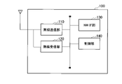
- FIG. 3 is a functional block configuration diagram of the wireless communication node 100.
- FIG. 4 is a diagram showing a network configuration example of scenario 1-a.
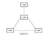
- FIG. 5 is a diagram showing a network configuration example of scenario 1-b.
- FIG. 6 is a diagram showing a network configuration example of Scenario 2.
- FIG. FIG. 7 is a diagram showing a network configuration example of Scenario 3.
- FIG. 8 is a diagram showing links between communication nodes.
- FIG. 9 is a diagram showing an example of a signal/data configuration.
- FIG. 10 shows the signal/data configuration in Option 1-1.
- FIG. 11 shows the signal/data configuration in Option 1-2.
- FIG. 12 shows the signal/data configuration in Option 1-3.
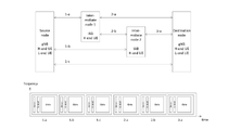
- FIG. 13 is a diagram showing a Source node, a Destination node, an intermediate node, and a correspondence relationship between links and signal/data configurations between them.
- FIG. 14 is a diagram showing a configuration when the node types in Option2-1 and Option2-2 are S: gNB (UE), D: UE (gNB), and I: IAB/gNB.
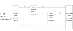
- FIG. 15 is a diagram showing a configuration when the types of nodes are S: gNB, D: UE, and I: High-end UE.
- FIG. 16 is a diagram showing a configuration when the types of nodes are S: UE, D: UE, and I: High-end UE.
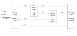
- FIG. 17 is a diagram showing a configuration when the types of nodes are S: UE, D: UE, and I: IAB/gNB.
- FIG. 18 shows method1.
- FIG. 4 is a diagram showing a configuration example of Node to node (each link);
- FIG. 19 shows method2.
- FIG. 4 is a diagram showing a configuration example of Source to destination (E2E);
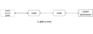
- FIG. 20 shows method3.
- FIG. 4 is a diagram showing a configuration example of gNB to node;
- FIG. 21 is a diagram showing an example of hardware configurations of the CU 50 and the wireless communication node 100. As shown in FIG.
- FIG. 1 is an overall schematic configuration diagram of a radio communication system 10 according to the present embodiment.
- the radio communication system 10 is a radio communication system according to 5G New Radio (NR) to 6G, and includes a plurality of radio communication nodes 100 (as shown, Central Unit (CU), base station (gNB), HAPS (High Altitude Platform Station), IAB (Integrated Access and Backhaul) nodes, terminals (UE: User Equipment), etc. can also be "wireless communication nodes").
- FIG. 2 is a diagram showing a configuration example of upper nodes, peer nodes, and lower nodes.
- the radio communication system 10 includes an upper node 100-01, peer nodes 100-1, 100-2, 100-02, and a lower node 100-3.
- These wireless communication nodes 100 can set up wireless access with UEs and wireless backhaul (BH) between the wireless communication nodes. Specifically, a backhaul (transmission path) is set by a wireless link between the wireless communication node 100-1 and the wireless communication node 100-01, and between the wireless communication node 100-1 and the wireless communication node 100-3. be done.
- BH wireless backhaul
- IAB Integrated Access and Backhaul
- the IAB will reuse existing functions and interfaces defined for wireless access.
- MT Mobile-Termination
- gNB-DU Distributed Unit
- gNB-CU Central Unit
- UPF User Plane Function
- AMF Access and Mobility Management Function
- SMF Session Management Function
- NR Uu MT to gNB/DU
- F1, NG, X2 and N4 are used as baselines.
- the wireless communication node 100 can be connected to the NR radio access network (NG-RAN) and core network (Next Generation Core (NGC) or 5GC) via a wired transmission line such as fiber transport (see FIG. 1).
- NG-RAN/NGC includes a Central Unit (CU), which is a communication node.
- CU Central Unit
- the CU may be configured by any one or a combination of the UPF, AMF, and SMF described above.
- the CU may be a gNB-CU as described above.
- the direction from the upper node to the lower node is the DL direction, and the direction from the lower node to the upper node is the UL direction.
- a radio link established between the lower node 100-3 such as the UE and the peer node 100-1 or the upper node 100-01 is called a radio access link.
- the radio link is composed of DL Access in the DL direction and UL Access in the UL direction.
- the radio access link from the node 100-1 to the upper node 100-01 is called an uplink (UL), and the radio access link from the node 100-1 to the lower node 100-3 is called a downlink (DL).
- a link from -1 to peer node 100-2 or peer node 100-02 is sometimes called a side link.
- UE2 can directly transmit and receive with the gNB and at the same time communicate via multiple links (eg via UE1, via IAB-UE3).
- RAN radio access network
- the radio communication node 100 that constitutes the mobile communication system of the present embodiment communicates with a plurality of communication nodes 100 that have different or identical functions.
- a communication node includes a node corresponding to a base station (node01), a node corresponding to a mobile station (node3), a node corresponding to a mobile station/IAB (node2), and simultaneous/TDM/FDM/SDM ( Simultaneous/time division multiplexing/frequency division multiplexing/spatial division multiplexing) is possible.
- Each communication node 100 may be ranked according to its function or communication method with a communication node (eg, gNB) serving as a starting point (eg, the number of communication nodes intervening between itself and the gNB). For example, if node1 is the starting point, node01 may be treated as an upper node, node2 and node3 as lower nodes, or, for example, node2 (in the case of UE) connected to gNB may be treated as a peer node.
- a communication node eg, gNB
- gNB serving as a starting point
- node01 may be treated as an upper node
- node2 and node3 as lower nodes
- node2 in the case of UE
- peer node may be treated as a peer node.
- a higher-level node is, for example, a node that performs functions and roles such as synchronization-related signals/notifications, control-related information transmission sources, and RRC connection destinations.
- a lower node is, for example, a node that serves as a transmission destination of information related to synchronization, a signal/notification related to synchronization, or a node that performs a function/role of connecting an RRC connection.
- wireless access may be half-duplex or full-duplex.
- FIG. 3 is a functional block configuration diagram of the radio communication node 100A that constitutes the parent node.
- the wireless communication node 100 includes a wireless transmission section 110, a wireless reception section 120, a NW IF section 130, and a control section 140.
- FIG. 1 is a functional block configuration diagram of the radio communication node 100A that constitutes the parent node.
- the wireless communication node 100 includes a wireless transmission section 110, a wireless reception section 120, a NW IF section 130, and a control section 140.
- the wireless transmission unit 110 transmits wireless signals according to 5G to 6G specifications. Also, the radio receiving unit 120 receives radio signals conforming to 5G to 6G specifications. In this embodiment, the wireless transmission unit 110 and the wireless reception unit 120 perform wireless communication with another wireless communication node 100.
- FIG. 1 A wireless communication node 100.
- the NW IF unit 130 is a connection unit that can connect with multiple wireless communication nodes (including upper nodes, lower nodes, and peer nodes) with the same or different functions or roles.
- the NW IF unit 130 provides a communication interface that realizes connection with the NGC side or the like.
- the NW IF unit 130 may include interfaces such as X2, Xn, N2, N3.
- the control unit 140 functions as a control unit that controls connection by a connection unit such as the NW IF unit 130.
- a connection unit such as the NW IF unit 130.
- the control unit 140 is not limited to controlling the NW IF unit 130 of its own wireless communication node 100, and may control the NW IF unit 130 of another wireless communication node 100.
- the control unit 140 may have the NW IF unit 130 of its own wireless communication node 100 controlled by another wireless communication node 100 .
- control unit 140 enables connection control from other specific wireless communication nodes 100, or allows the wireless communication node 100 itself to control connections to all other wireless communication nodes 100. may be
- control unit 140 may disable connection control from another specific wireless communication node 100, or may disable connection control of each other wireless communication node 100 by its own wireless communication node 100.
- connection control method may be unified regardless of the node shape, or may be different depending on the node shape.
- the target of connection control by the control unit 140 may be at least one of synchronization, connection type, identification, routing, and resource allocation.
- inter-node/E2E or the like may be used as the link to be controlled.
- the control information for the other wireless communication node 100 by the control unit 140 may be transmitted using an appropriate channel or signaling.
- Control channels include control channels and data channels.
- Control channels include PDCCH (Physical Downlink Control Channel), PUCCH (Physical Uplink Control Channel), PRACH (Physical Random Access Channel), and PBCH (Physical Broadcast Channel).
- data channels include PDSCH (Physical Downlink Shared Channel) and PUSCH (Physical Uplink Shared Channel).
- PDSCH Physical Downlink Shared Channel
- PUSCH Physical Uplink Shared Channel
- Reference signals include demodulation reference signal (DMRS), sounding reference signal (SRS), phase tracking reference signal (PTRS), and channel state information-reference signal (CSI-RS). and a reference signal.
- Data may also refer to data transmitted over a data channel.
- UCI is control information that is the target of Downlink Control Information (DCI) and is transmitted via PUCCH or PUSCH.
- DCI Downlink Control Information
- UCI may include SR (Scheduling Request), HARQ (Hybrid Automatic repeat request) ACK/NACK, and CQI (Channel Quality Indicator).
- connection control A specific example of connection control will be described later.
- the wireless communication system 10, the wireless communication node 100, the connection unit (NW IF unit 130), the control unit 140, etc. use a known wired mesh network technology to make the wireless communication network (RAN) a mesh type. It may be used.
- RAN wireless communication network
- FIGS. 4 to 7 are diagrams showing control relationships among communication nodes in scenarios 1-a, 1-b, 2, and 3.
- FIG. 4 to 7 are diagrams showing control relationships among communication nodes in scenarios 1-a, 1-b, 2, and 3.
- a specific node such as a core NW/base station
- the dotted lines in the figure indicate links through which connection control information (signals) are sent between nodes.
- the nodes (nodes 1 to 3) subject to connection control are located in an area such as a base station.
- Each node (node1-3) receives connection control from a specific node (node0).
- the specific node (node0)/each node (node1-3 ) relays the signal of the base station (node0) or has the function of a base station (like node1).
- node 0 such as a core NW/base station cannot control each node (nodes 1 to 3), and each node is not controlled.
- node 1 to 3 any one of the following options may be adopted.
- 2-a Each node autonomously controls itself and links between nodes 2-b Nodes substituting for base stations can/will control all nodes
- Scenario 1 and Scenario 2 are allowed to coexist.
- a specific node such as a core network/base station can control all nodes, and each node is controlled.
- the indicated means may be used to control a node having means for communicating with the core NW/base station.
- 1-a Connect directly to core NW/base station 1-b Connect with core NW/base station equivalent nodes (e.g. IAB nodes)
- core NW/base station equivalent nodes e.g. IAB nodes
- core NW/base station equivalent nodes e.g. IAB nodes
- Indirect connection with core NW/base station for example, connection with a node that relays base station signals
- Option 1-1 Everything is controlled by the core NW/base station
- Option 1-2 Partially controlled by core NW/base station
- Option 1-3 Mainly controlled by core NW/base station
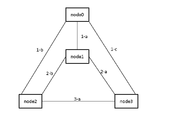
- FIG. 8 is a diagram showing links between communication nodes.
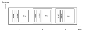
- FIG. 9 is a diagram showing an example of a signal/data configuration.
- the link names shown in FIG. 8 are used for the following description.
- the signals and data to be transmitted are the synchronization signal, control information, and data of link 1 (links 1-a, 1-b, and 1-c) in the first stage; Synchronization signals, control information, and data of link 2 (links 2-a and 2-b) at the stage and link 3 (link 3-a) at the third stage are arranged along time in this order.
- FIG. 10 shows the signal/data configuration in Option 1-1.
- FIG. 11 shows the signal/data configuration in Option 1-2.
- FIG. 12 shows the signal/data configuration in Option 1-3.
- a solid line indicates information rewritable by another wireless communication node 100, and a dashed line indicates information not rewritable by another wireless communication node 100.
- Option 1-1 everything is controlled by the core NW/base station (node0). All are implemented. For example, synchronization of each link, scheduling, resource control, etc. are all controlled. Therefore, as shown in FIG. 10, all information of links 1 to 3 can be rewritten by another communication node (node0).
- Option 1-2 some are controlled by the core NW/base station.
- core NW/base station and each node controllable functions/roles are distributed.
- the core NW/base station node0
- the core NW/base station may control synchronization, and resource allocation for each link may be performed by each node.
- the signal/data configuration as shown in FIG. 11, some information (control information, etc.) can be rewritten by another communication node (node0).
- the core NW/base station (node0) is largely controlled.
- a broad framework of control such as the controllable range of each node is performed.
- the configuration of radio resources available to each node may be controlled.
- Option2-1 Unification of control methods and mechanisms regardless of the functions and types of connected nodes
- Option2-2 Control methods and mechanisms differ according to the function and type of the connected node
- Option 2-2 it is possible to vary the control method and mechanism according to the node functions and types of the signal/data source and destination.
- gNB, High end UE, Low end UE, etc. correspond to Source node and Destination node.
- the Low-end UE is, for example, a terminal that only has the function of communicating with a base station.
- a high-end UE is, for example, a terminal that, in addition to the above, has an inter-terminal communication function, a relay function, and the like.
- An intermediate node (eg, IAB node, High end UE) can be interposed between the Source node and the Destination node.
- the control method/mechanism can be varied according to the type of intermediate node.
- FIG. 13 is a diagram showing a Source node, a Destination node, an intermediate node, and a correspondence relationship between links and signal/data configurations between them.
- FIG. 14 is a diagram showing a configuration when the type of each node in Option2-1 and Option2-2 is S: gNB (UE), D: UE (gNB), and I: IAB/gNB.
- S is a Source node
- D is a Destination node
- I is an Intermediate node.
- the signals/data in FIG. 13 corresponding to all the links in FIG. 14 can be rewritten as shown in FIG.
- FIG. 15 is a diagram showing a configuration when the types of each node are S: gNB, D: UE, and I: High-end UE.
- S gNB
- D UE
- I High-end UE.
- the signal/data in FIG. 13 corresponding to the link in FIG. 15 can be partially rewritten as shown in FIG.
- FIG. 16 is a diagram showing a configuration when the types of each node are S: UE, D: UE, and I: High-end UE. In this case, the signals/data in FIG. 13 corresponding to the link in FIG. 16 cannot be rewritten as shown in FIG.
- FIG. 17 is a diagram showing a configuration when the type of each node is S: UE, D: UE, I: IAB/gNB.
- the signals/data in FIG. 13 corresponding to the links in FIG. 17 can be rewritten as shown in FIG.
- Option 2-1 the control method and mechanism are unified regardless of the function and type of the connected node
- Option 2-2 the control method and mechanism are unified according to the function and type of the connected node It is possible to vary the control method/mechanism.
- the following method may be adopted as the link to be controlled. method1. Node to node (each link) That is, control is performed for each link between each node. method2. Source to destination (E2E) That is, it controls multiple links that configure E2E. method3. gNB to node Controls links between gNBs and nodes.
- FIG. 4 is a diagram showing a configuration example of Node to node (each link); As shown in FIG. 18, a specific node (node0) is configured so that each node can be controlled.
- FIG. 19 shows method2.
- FIG. 4 is a diagram showing a configuration example of Source to destination (E2E); As shown in FIG. 19, in this example, a specific node (node0) controls a plurality of links forming E2E in a unified manner.
- node0 a specific node
- FIG. 4 is a diagram showing a configuration example of gNB to node; As shown in FIG. 20, in this example, a particular node (node0) controls only the link between node1 source (gNB) and the node. That is, only the link of the double arrow on the left side of the figure is controlled, and the control of the center arrow and the left double arrow is not performed.
- node0 node0
- gNB node1 source
- At least one of the following may be adopted as a control target for the core NW/base station and the like.
- ⁇ Connection type Node/E2E connection type ⁇ Routing Whether or not routing is specified ⁇ Node identification Identifier allocation for each node allocation
- connection unit 130 capable of connecting to a plurality of wireless communication nodes (wireless communication nodes 100) having the same or different functions or roles
- connection unit (NW IF unit 130 ) capable of connecting to a plurality of wireless communication nodes (wireless communication nodes 100) having the same or different functions or roles
- control unit 140 controls connection by
- control unit 140 enables connection control from another specific wireless communication node 100, or allows its own wireless communication node 100 to perform connection control for all other wireless communication nodes. make it possible.
- connection control of other nodes such as UEs to a specific node such as a gNB, and it is possible to appropriately set the connection control relationship between wireless communication nodes according to the node type.
- control unit 130 disables connection control from another specific wireless communication node 100, or disables the connection control of its own wireless communication node 100 to each other wireless communication node.
- connection control relationship between wireless communication nodes according to the node type, such as preventing the gNB from receiving connection control from the UE, for example.
- connection control method is uniform regardless of the node shape or node type, or is different depending on the node shape or node type.
- connection control targets are at least one of synchronization, connection type, identification, routing, and resource allocation.
- the names of the parent node, the IAB node, and the child node were used.
- the names may be different as long as the node configuration is adopted. For example, they may simply be called first and second nodes, or they may be called upper nodes, lower nodes, relay nodes, intermediate nodes, and the like.
- the wireless communication node may be simply referred to as a communication device or a communication node, or may be read as a wireless base station.
- DL and UL downlink
- forward ring reverse link
- access link and backhaul
- backhaul may be interchanged or associated.
- first link, second link, first direction, second direction, etc. may simply be used.
- each functional block may be implemented using one device physically or logically coupled, or directly or indirectly using two or more physically or logically separate devices (e.g. , wired, wireless, etc.) and may be implemented using these multiple devices.
- a functional block may be implemented by combining software in the one device or the plurality of devices.
- Functions include judging, determining, determining, calculating, calculating, processing, deriving, investigating, searching, checking, receiving, transmitting, outputting, accessing, resolving, selecting, choosing, establishing, comparing, assuming, expecting, assuming, Broadcasting, notifying, communicating, forwarding, configuring, reconfiguring, allocating, mapping, assigning, etc. can't
- a functional block (component) that performs transmission is called a transmitting unit or transmitter.
- the implementation method is not particularly limited.
- FIG. 21 is a diagram showing an example of the hardware configuration of the device.
- the device may be configured as a computer device including a processor 1001, a memory 1002, a storage 1003, a communication device 1004, an input device 1005, an output device 1006, a bus 1007, and the like.
- the term "apparatus” can be read as a circuit, device, unit, or the like.
- the hardware configuration of the device may be configured to include one or more of each device shown in the figure, or may be configured without some of the devices.
- FIG. 21 is a diagram showing an example of hardware configurations of the CU 50 and the wireless communication node 100. As shown in FIG.
- Each function of the device is performed by loading predetermined software (program) on hardware such as the processor 1001 and the memory 1002, the processor 1001 performs calculations, the communication by the communication device 1004 is controlled, the memory 1002 and It is realized by controlling at least one of data reading and writing in the storage 1003 .
- predetermined software program
- a processor 1001 operates an operating system and controls the entire computer.
- the processor 1001 may be configured with a central processing unit (CPU) including interfaces with peripheral devices, a controller, arithmetic units, registers, and the like.
- CPU central processing unit
- the processor 1001 reads programs (program codes), software modules, data, etc. from at least one of the storage 1003 and the communication device 1004 to the memory 1002, and executes various processes according to them.
- programs program codes
- software modules software modules
- data etc.
- the various processes described above may be executed by one processor 1001, or may be executed by two or more processors 1001 simultaneously or sequentially.
- Processor 1001 may be implemented by one or more chips. Note that the program may be transmitted from a network via an electric communication line.
- the memory 1002 is a computer-readable recording medium, and is composed of at least one of Read Only Memory (ROM), Erasable Programmable ROM (EPROM), Electrically Erasable Programmable ROM (EEPROM), Random Access Memory (RAM), etc. may be
- ROM Read Only Memory
- EPROM Erasable Programmable ROM
- EEPROM Electrically Erasable Programmable ROM
- RAM Random Access Memory
- the memory 1002 may also be called a register, cache, main memory (main storage device), or the like.
- the memory 1002 can store programs (program code), software modules, etc. capable of executing a method according to an embodiment of the present disclosure.
- the storage 1003 is a computer-readable recording medium, for example, an optical disc such as a Compact Disc ROM (CD-ROM), a hard disk drive, a flexible disc, a magneto-optical disc (for example, a compact disc, a digital versatile disc, a Blu-ray disk), smart card, flash memory (eg, card, stick, key drive), floppy disk, magnetic strip, and/or the like.
- Storage 1003 may also be referred to as an auxiliary storage device.
- the recording medium described above may be, for example, a database, server, or other suitable medium including at least one of memory 1002 and storage 1003 .
- the communication device 1004 is hardware (transmitting/receiving device) for communicating between computers via at least one of a wired network and a wireless network, and is also called a network device, a network controller, a network card, a communication module, or the like.
- the communication device 1004 includes a high-frequency switch, duplexer, filter, frequency synthesizer, etc., for realizing at least one of frequency division duplex (FDD) and time division duplex (TDD).
- FDD frequency division duplex
- TDD time division duplex
- the input device 1005 is an input device (for example, keyboard, mouse, microphone, switch, button, sensor, etc.) that receives input from the outside.
- the output device 1006 is an output device (eg, display, speaker, LED lamp, etc.) that outputs to the outside. Note that the input device 1005 and the output device 1006 may be integrated (for example, a touch panel).
- each device such as the processor 1001 and the memory 1002 is connected by a bus 1007 for communicating information.
- the bus 1007 may be configured using a single bus, or may be configured using different buses between devices.
- the device includes hardware such as a microprocessor, digital signal processor (DSP), application specific integrated circuit (ASIC), programmable logic device (PLD), field programmable gate array (FPGA), etc.
- DSP digital signal processor
- ASIC application specific integrated circuit
- PLD programmable logic device
- FPGA field programmable gate array
- notification of information is not limited to the aspects/embodiments described in the present disclosure, and may be performed using other methods.
- the notification of information may include physical layer signaling (e.g., Downlink Control Information (DCI), Uplink Control Information (UCI), higher layer signaling (e.g., RRC signaling, Medium Access Control (MAC) signaling, broadcast information (Master Information Block (MIB), System Information Block (SIB), other signals, or combinations thereof, and RRC signaling may also be referred to as RRC messages, e.g., RRC Connection Setup ) message, RRC Connection Reconfiguration message, or the like.
- DCI Downlink Control Information
- UCI Uplink Control Information
- RRC signaling e.g., RRC signaling, Medium Access Control (MAC) signaling, broadcast information (Master Information Block (MIB), System Information Block (SIB), other signals, or combinations thereof
- RRC signaling may also be referred to as RRC messages, e.g., RRC Connection Setup ) message, R
- LTE Long Term Evolution
- LTE-A LTE-Advanced
- SUPER 3G IMT-Advanced
- 4G 5th generation mobile communication system
- 5G Future Radio Access
- FAA New Radio
- NR New Radio
- W-CDMA® GSM®
- CDMA2000 Code Division Multiple Access 2000
- UMB Ultra Mobile Broadband
- IEEE 802.11 Wi-Fi®
- IEEE 802.16 WiMAX®
- IEEE 802.20 Ultra-WideBand (UWB), Bluetooth®
- next-generation systems enhanced based on these may be applied to one.
- a plurality of systems may be applied in combination (for example, a combination of at least one of LTE and LTE-A and 5G).
- a specific operation that is performed by a base station in the present disclosure may be performed by its upper node in some cases.
- various operations performed for communication with a terminal may be performed by the base station and other network nodes other than the base station (e.g. MME or S-GW, etc., but not limited to).
- MME or S-GW network nodes
- the case where there is one network node other than the base station is exemplified above, it may be a combination of a plurality of other network nodes (for example, MME and S-GW).
- Information, signals can be output from a higher layer (or a lower layer) to a lower layer (or a higher layer). It may be input and output via multiple network nodes.
- Input/output information may be stored in a specific location (for example, memory) or managed using a management table. Input and output information may be overwritten, updated, or appended. The output information may be deleted. The entered information may be transmitted to other devices.
- the determination may be made by a value represented by one bit (0 or 1), by a true/false value (Boolean: true or false), or by numerical comparison (for example, a predetermined value).
- notification of predetermined information is not limited to being performed explicitly, but may be performed implicitly (for example, not notifying the predetermined information). good too.
- Software whether referred to as software, firmware, middleware, microcode, hardware description language or otherwise, includes instructions, instruction sets, code, code segments, program code, programs, subprograms, and software modules. , applications, software applications, software packages, routines, subroutines, objects, executables, threads of execution, procedures, functions, and the like.
- software, instructions, information, etc. may be transmitted and received via a transmission medium.
- the Software uses wired technology (coaxial cable, fiber optic cable, twisted pair, Digital Subscriber Line (DSL), etc.) and/or wireless technology (infrared, microwave, etc.) to access websites, Wired and/or wireless technologies are included within the definition of transmission medium when sent from a server or other remote source.
- wired technology coaxial cable, fiber optic cable, twisted pair, Digital Subscriber Line (DSL), etc.
- wireless technology infrared, microwave, etc.
- data, instructions, commands, information, signals, bits, symbols, chips, etc. may refer to voltages, currents, electromagnetic waves, magnetic fields or magnetic particles, light fields or photons, or any of these. may be represented by a combination of
- the channel and/or symbols may be signaling.
- a signal may also be a message.
- a component carrier may also be called a carrier frequency, a cell, a frequency carrier, or the like.
- system and “network” used in this disclosure are used interchangeably.
- information, parameters, etc. described in the present disclosure may be expressed using absolute values, may be expressed using relative values from a predetermined value, or may be expressed using other corresponding information.
- radio resources may be indexed.
- base station BS
- radio base station fixed station
- NodeB NodeB
- eNodeB eNodeB
- gNodeB gNodeB
- a base station may also be referred to by terms such as macrocell, small cell, femtocell, picocell, and the like.
- a base station can accommodate one or more (eg, three) cells (also called sectors). When a base station accommodates multiple cells, the overall coverage area of the base station can be partitioned into multiple smaller areas, each smaller area corresponding to a base station subsystem (e.g., a small indoor base station (Remote Radio)). Head: RRH) can also provide communication services.
- a base station subsystem e.g., a small indoor base station (Remote Radio)
- Head: RRH can also provide communication services.
- cell refers to part or all of the coverage area of at least one of a base station and base station subsystem that provides communication services in this coverage.
- MS Mobile Station
- UE User Equipment
- a mobile station is defined by those skilled in the art as a subscriber station, mobile unit, subscriber unit, wireless unit, remote unit, mobile device, wireless device, wireless communication device, remote device, mobile subscriber station, access terminal, mobile terminal, wireless It may also be called a terminal, remote terminal, handset, user agent, mobile client, client, or some other suitable term.
- At least one of the base station and mobile station may be called a transmitting device, a receiving device, a communication device, or the like.
- At least one of the base station and the mobile station may be a device mounted on a mobile object, the mobile object itself, or the like.
- the mobile body may be a vehicle (e.g., car, airplane, etc.), an unmanned mobile body (e.g., drone, self-driving car, etc.), or a robot (manned or unmanned ).
- at least one of the base station and the mobile station includes devices that do not necessarily move during communication operations.
- at least one of the base station and mobile station may be an Internet of Things (IoT) device such as a sensor.
- IoT Internet of Things
- the base station in the present disclosure may be read as a mobile station (user terminal, hereinafter the same).
- communication between a base station and a mobile station is replaced with communication between multiple mobile stations (for example, Device-to-Device (D2D), Vehicle-to-Everything (V2X), etc.)
- the mobile station may have the functions that the base station has.
- words such as "up” and “down” may be replaced with words corresponding to communication between terminals (for example, "side”).
- uplink channels, downlink channels, etc. may be read as side channels.
- a mobile station in the present disclosure may be read as a base station.
- the base station may have the functions that the mobile station has.
- a radio frame may consist of one or more frames in the time domain. Each frame or frames in the time domain may be referred to as a subframe. A subframe may also consist of one or more slots in the time domain. A subframe may be a fixed time length (eg, 1 ms) independent of numerology.
- a numerology may be a communication parameter that applies to the transmission and/or reception of a signal or channel. Numerology, for example, subcarrier spacing (SCS), bandwidth, symbol length, cyclic prefix length, transmission time interval (TTI), number of symbols per TTI, radio frame structure, transmission and reception specific filtering operations performed by the receiver in the frequency domain, specific windowing operations performed by the transceiver in the time domain, and/or the like.
- SCS subcarrier spacing
- TTI transmission time interval
- number of symbols per TTI radio frame structure
- transmission and reception specific filtering operations performed by the receiver in the frequency domain specific windowing operations performed by the transceiver in the time domain, and/or the like.
- a slot may consist of one or more symbols (Orthogonal Frequency Division Multiplexing (OFDM) symbols, Single Carrier Frequency Division Multiple Access (SC-FDMA) symbols, etc.) in the time domain.
- OFDM Orthogonal Frequency Division Multiplexing
- SC-FDMA Single Carrier Frequency Division Multiple Access
- a slot may be a unit of time based on numerology.
- a slot may contain multiple mini-slots. Each minislot may consist of one or more symbols in the time domain. A minislot may also be referred to as a subslot. A minislot may consist of fewer symbols than a slot.
- a PDSCH (or PUSCH) that is transmitted in time units larger than a minislot may be referred to as PDSCH (or PUSCH) mapping type A.
- PDSCH (or PUSCH) transmitted using minislots may be referred to as PDSCH (or PUSCH) mapping type B.
- Radio frames, subframes, slots, minislots and symbols all represent time units when transmitting signals. Radio frames, subframes, slots, minislots and symbols may be referred to by other corresponding designations.
- one subframe may be called a transmission time interval (TTI)
- TTI transmission time interval
- multiple consecutive subframes may be called a TTI
- one slot or one minislot may be called a TTI. That is, at least one of the subframe and TTI may be a subframe (1ms) in existing LTE, may be a period shorter than 1ms (eg, 1-13 symbols), or a period longer than 1ms may be Note that the unit representing the TTI may be called a slot, minislot, or the like instead of a subframe.
- TTI refers to, for example, the minimum scheduling time unit in wireless communication.
- a base station performs scheduling to allocate radio resources (frequency bandwidth, transmission power, etc. that can be used by each user terminal) to each user terminal on a TTI basis.
- radio resources frequency bandwidth, transmission power, etc. that can be used by each user terminal
- the TTI may be a transmission time unit for channel-encoded data packets (transport blocks), code blocks, codewords, etc., or may be a processing unit for scheduling, link adaptation, etc. Note that when a TTI is given, the time interval (for example, the number of symbols) in which transport blocks, code blocks, codewords, etc. are actually mapped may be shorter than the TTI.
- one slot or one minislot is called a TTI
- one or more TTIs may be the minimum scheduling time unit.
- the number of slots (the number of mini-slots) constituting the minimum time unit of the scheduling may be controlled.
- a TTI with a time length of 1 ms may be called a normal TTI (TTI in LTE Rel.8-12), normal TTI, long TTI, normal subframe, normal subframe, long subframe, slot, etc.
- TTI that is shorter than a regular TTI may also be called a shortened TTI, a short TTI, a partial or fractional TTI, a shortened subframe, a short subframe, a minislot, a subslot, a slot, and so on.
- long TTI for example, normal TTI, subframe, etc.
- short TTI for example, shortened TTI, etc.
- a TTI having a TTI length greater than or equal to this value may be read as a replacement.
- a resource block is a resource allocation unit in the time domain and frequency domain, and may include one or more consecutive subcarriers in the frequency domain.
- the number of subcarriers included in an RB may be the same regardless of neurology, and may be 12, for example.
- the number of subcarriers included in an RB may be determined based on neumerology.
- the time domain of an RB may include one or more symbols and may be 1 slot, 1 minislot, 1 subframe, or 1 TTI long.
- One TTI, one subframe, etc. may each consist of one or more resource blocks.
- One or more RBs are physical resource blocks (Physical RB: PRB), sub-carrier groups (SCG), resource element groups (REG), PRB pairs, RB pairs, etc. may be called.
- PRB Physical resource blocks
- SCG sub-carrier groups
- REG resource element groups
- PRB pairs RB pairs, etc.
- a resource block may be composed of one or more resource elements (Resource Element: RE).
- RE resource elements
- 1 RE may be a radio resource region of 1 subcarrier and 1 symbol.
- a Bandwidth Part (which may also be called a Bandwidth Part) represents a subset of contiguous common resource blocks (RBs) for a neumerology in a carrier. good.
- the common RB may be identified by an RB index based on the common reference point of the carrier.
- PRBs may be defined in a BWP and numbered within that BWP.
- BWP may include BWP for UL (UL BWP) and BWP for DL (DL BWP).
- BWP may include BWP for UL (UL BWP) and BWP for DL (DL BWP).
- One or more BWPs may be configured in one carrier for a UE.
- At least one of the configured BWPs may be active, and the UE may not expect to transmit or receive a given signal/channel outside the active BWP.
- BWP bitmap
- radio frames, subframes, slots, minislots and symbols described above are only examples.
- the number of subframes included in a radio frame the number of slots per subframe or radio frame, the number of minislots included in a slot, the number of symbols and RBs included in a slot or minislot, the number of Configurations such as the number of subcarriers and the number of symbols in a TTI, symbol length, cyclic prefix (CP) length, etc.
- CP cyclic prefix
- connection means any direct or indirect connection or coupling between two or more elements, It can include the presence of one or more intermediate elements between two elements being “connected” or “coupled.” Couplings or connections between elements may be physical, logical, or a combination thereof. For example, “connection” may be read as "access”.
- two elements are defined using at least one of one or more wires, cables and printed electrical connections and, as some non-limiting and non-exhaustive examples, in the radio frequency domain. , electromagnetic energy having wavelengths in the microwave and light (both visible and invisible) regions, and the like.
- the reference signal can also be abbreviated as Reference Signal (RS), and may also be called Pilot depending on the applicable standard.
- RS Reference Signal
- any reference to elements using the "first,” “second,” etc. designations used in this disclosure does not generally limit the quantity or order of those elements. These designations may be used in this disclosure as a convenient method of distinguishing between two or more elements. Thus, references to first and second elements do not imply that only two elements may be employed therein or that the first element must precede the second element in any way.
- determining and “determining” used in this disclosure may encompass a wide variety of actions.
- “Judgement” and “determination” are, for example, judging, calculating, computing, processing, deriving, investigating, looking up, searching, inquiring (eg, lookup in a table, database, or other data structure), ascertaining as “judged” or “determined”, and the like.
- "judgment” and “determination” are used for receiving (e.g., receiving information), transmitting (e.g., transmitting information), input, output, access (accessing) (for example, accessing data in memory) may include deeming that a "judgment” or “decision” has been made.
- judgment and “decision” are considered to be “judgment” and “decision” by resolving, selecting, choosing, establishing, comparing, etc. can contain.
- judgment and “decision” may include considering that some action is “judgment” and “decision”.
- judgment (decision) may be read as “assuming”, “expecting”, “considering”, or the like.
- a and B are different may mean “A and B are different from each other.”
- the term may also mean that "A and B are different from C”.
- Terms such as “separate,” “coupled,” etc. may also be interpreted in the same manner as “different.”
- Radio communication system 50 CU 100 wireless communication node 110 wireless transmission unit 120 wireless reception unit 130 NW IF unit 140 control unit UE 200 1001 Processor 1002 Memory 1003 Storage 1004 Communication Device 1005 Input Device 1006 Output Device 1007 Bus
Landscapes
- Engineering & Computer Science (AREA)
- Computer Networks & Wireless Communication (AREA)
- Signal Processing (AREA)
- Databases & Information Systems (AREA)
- Mobile Radio Communication Systems (AREA)
Abstract
Description
図1は、本実施形態に係る無線通信システム10の全体概略構成図である。無線通信システム10は、5G New Radio(NR)乃至6Gに従った無線通信システムであり、複数の無線通信ノード100(図示の如くCentral Unit(CU)や基地局(gNB),HAPS(High Altitude Platform Station),IAB(Integrated Access and Backhaul)ノード及び端末(UE:User Equipment)等も「無線通信ノード」になり得る。)によって構成される。ここで、図2は、上位ノード、同位ノード、および、下位ノードの構成例を示す図である。
次に、無線通信システム10を構成する無線通信ノード100の機能ブロック構成について説明する。
図3は、親ノードを構成する無線通信ノード100Aの機能ブロック構成図である。図3に示すように、無線通信ノード100は、無線送信部110、無線受信部120、NW IF部130、および制御部140を備える。
次に、無線通信システム10の動作および制御方法について説明する。具体的には、無線通信システム10における通信ノード100間の動作と制御例について説明する。
<Scenario 1>
図4に示すように、このScenario 1の例では、コアNW/基地局など、特定のノード(この例では、node0)が全てのノードを制御可能であり、全てのノードは特定のノードに制御される。図の点線は、ノード間で接続制御の情報(信号)が送られるリンクを示している。
2-a 各ノードが自身及びノード間のリンク等の制御を自律的に行う
2-b 基地局に代替するノードが全てのノードを制御可能/制御される
なお、Scenario 1では、コアNW/基地局など、特定のノードが全てのノードを制御可能であり、各ノードは制御されるが、各通信ノードは、以下に示す手段を用いて、コアNW/基地局と通信を行う手段を有するノードに対して制御を行ってもよい。
1-a コアNW/基地局と直接接続する
1-b コアNW/基地局に準ずるノード(例えばIABノード)と接続する
1-b コアNW/基地局と間接的に接続する(例えば,基地局の信号をリレーするノードと接続)
Option 1-1:コアNW/基地局に全てを制御される
Option 1-2:コアNW/基地局に一部を制御される
Option 1-3:コアNW/基地局に大枠を制御される
Scenario 2では、コアNW/基地局など、特定のノードは、各ノードの制御が不可能であり、各ノードは制御されない。ここで、以下のオプションのいずれかを採用してもよい。
2-a 各ノードが自身及びノード間のリンク等の制御を自律的に行う。
2-b 基地局に代替するノードが、全てのノードを制御可能であり、各ノードは制御される(制御の範囲は、上述のScenario 1に準ずる)。
Option2-1:接続するノードの機能・種別によらず、制御の方法・仕組みが統一
Option2-2:接続するノードの機能・種別に応じた制御の方法・仕組みが異なる
Scenario 3の例では、Scenario 1とScenario 2が混在する。
method1.Node to node (each link)
すなわち、各ノード間のリンク毎に制御する。
method2.Source to destination (E2E)
すなわち、E2Eを構成する複数のリンクに対して制御する。
method3.gNB to node
gNBとノード間のリンクを制御する。
・同期
ノード間,ノード内の送信/受信タイミングなど
・接続種別
ノード/E2Eの接続種別
・ルーティング
ルーティング指定の有/無
・ノード識別
各ノードに対する識別子の割り当て
・リソース割当て
各ノード間のリンクに対するリソースの割り当て
上述した実施形態によれば、以下の作用効果が得られる。具体的には、本実施の形態は、機能または役割が同一または異なる複数の無線通信ノード(無線通信ノード100)と接続し得る接続部(NW IF部130)と、接続部(NW IF部130)による接続を制御する制御部(制御部140)と、を備える。
以上、実施例に沿って本発明の内容を説明したが、本発明はこれらの記載に限定されるものではなく、種々の変形及び改良が可能であることは、当業者には自明である。
サブフレームはさらに時間領域において1つまたは複数のスロットによって構成されてもよい。サブフレームは、ニューメロロジー(numerology)に依存しない固定の時間長(例えば、1ms)であってもよい。
50 CU
100 無線通信ノード
110 無線送信部
120 無線受信部
130 NW IF部
140 制御部
UE 200
1001 プロセッサ
1002 メモリ
1003 ストレージ
1004 通信装置
1005 入力装置
1006 出力装置
1007 バス
Claims (6)
- 機能または役割が同一または異なる複数の無線通信ノードと接続し得る接続部と、
前記接続部による接続を制御する制御部と、
を備える無線通信ノード。 - 前記制御部は、他の特定の無線通信ノードからの接続制御を可能とする、もしくは、自身の無線通信ノードが他の全ての無線通信ノードの接続制御を可能とする請求項1に記載の無線通信ノード。
- 前記制御部は、他の特定の無線通信ノードからの接続制御を不可とする、もしくは、自身の無線通信ノードが他の各無線通信ノードからの接続制御されることを不可とする請求項1または2に記載の無線通信ノード。
- 請求項2または3に記載の接続制御の方法が、ノード形状もしくはノード種別によらず統一である、または、ノード形状もしくはノード種別に応じて異なる無線通信ノード。
- 前記接続制御の対象として、同期、接続種別、識別、ルーティング、および、リソース割当のうち、少なくとも一つである無線通信ノード。
- 機能または役割が同一または異なる複数の無線通信ノードと接続し得る接続部による接続を制御する制御ステップと、
前記制御ステップによる接続制御により他の前記無線通信ノードとの接続を行う接続ステップと、
を含む無線通信方法。
Priority Applications (5)
| Application Number | Priority Date | Filing Date | Title |
|---|---|---|---|
| US18/283,407 US20240179770A1 (en) | 2021-03-22 | 2021-03-22 | Radio communication node and radio communication method |
| JP2023508182A JPWO2022201262A1 (ja) | 2021-03-22 | 2021-03-22 | |
| EP21932873.9A EP4319459A4 (en) | 2021-03-22 | 2021-03-22 | WIRELESS COMMUNICATION NODES AND WIRELESS COMMUNICATION METHODS |
| PCT/JP2021/011805 WO2022201262A1 (ja) | 2021-03-22 | 2021-03-22 | 無線通信ノード、および、無線通信方法 |
| CN202180095793.8A CN116998217A (zh) | 2021-03-22 | 2021-03-22 | 无线通信节点以及无线通信方法 |
Applications Claiming Priority (1)
| Application Number | Priority Date | Filing Date | Title |
|---|---|---|---|
| PCT/JP2021/011805 WO2022201262A1 (ja) | 2021-03-22 | 2021-03-22 | 無線通信ノード、および、無線通信方法 |
Publications (1)
| Publication Number | Publication Date |
|---|---|
| WO2022201262A1 true WO2022201262A1 (ja) | 2022-09-29 |
Family
ID=83396447
Family Applications (1)
| Application Number | Title | Priority Date | Filing Date |
|---|---|---|---|
| PCT/JP2021/011805 Ceased WO2022201262A1 (ja) | 2021-03-22 | 2021-03-22 | 無線通信ノード、および、無線通信方法 |
Country Status (5)
| Country | Link |
|---|---|
| US (1) | US20240179770A1 (ja) |
| EP (1) | EP4319459A4 (ja) |
| JP (1) | JPWO2022201262A1 (ja) |
| CN (1) | CN116998217A (ja) |
| WO (1) | WO2022201262A1 (ja) |
Citations (1)
| Publication number | Priority date | Publication date | Assignee | Title |
|---|---|---|---|---|
| US20200351970A1 (en) * | 2019-05-02 | 2020-11-05 | Lg Electronics Inc. | Method for handling radio link problem by relay node in wireless communication system and apparatus therefor |
Family Cites Families (6)
| Publication number | Priority date | Publication date | Assignee | Title |
|---|---|---|---|---|
| US20030069949A1 (en) * | 2001-10-04 | 2003-04-10 | Chan Michele W. | Managing distributed network infrastructure services |
| CN104410985B (zh) * | 2014-10-20 | 2018-04-06 | 新华三技术有限公司 | 一种拓扑控制报文的处理方法和装置 |
| CN105681437B (zh) * | 2016-01-28 | 2019-07-19 | 华为技术有限公司 | 一种网络功能的实现方法和装置 |
| BR112021004236A2 (pt) * | 2018-09-14 | 2021-05-18 | Ntt Docomo, Inc. | aparelho de radiocomunicação e método de radiocomunicação de um aparelho de radiocomunicação |
| US11252042B2 (en) * | 2019-04-12 | 2022-02-15 | Huawei Technologies Co., Ltd. | Systems and methods for communication network customization |
| JP7681968B2 (ja) * | 2020-12-17 | 2025-05-23 | キヤノン株式会社 | Iabノード、iabノードの制御方法、およびプログラム |
-
2021
- 2021-03-22 WO PCT/JP2021/011805 patent/WO2022201262A1/ja not_active Ceased
- 2021-03-22 EP EP21932873.9A patent/EP4319459A4/en active Pending
- 2021-03-22 CN CN202180095793.8A patent/CN116998217A/zh active Pending
- 2021-03-22 US US18/283,407 patent/US20240179770A1/en active Pending
- 2021-03-22 JP JP2023508182A patent/JPWO2022201262A1/ja active Pending
Patent Citations (1)
| Publication number | Priority date | Publication date | Assignee | Title |
|---|---|---|---|---|
| US20200351970A1 (en) * | 2019-05-02 | 2020-11-05 | Lg Electronics Inc. | Method for handling radio link problem by relay node in wireless communication system and apparatus therefor |
Non-Patent Citations (3)
| Title |
|---|
| NTT DOCOMO, INC., DOCOMO 6G WHITE PAPER, February 2021 (2021-02-01), Retrieved from the Internet <URL:https://www.nttdocomo.co.jp/corporate/technology/whitepaper6g> |
| QUALCOMM INC, KDDI, AT&T, NOKIA, NOKIA SHANGHAI BELL, HUAWEI, ERICSSON, INTEL, LG ELECTRONICS, CMCC, SAMSUNG, ZTE, CATT, VIVO,: "pCR for TR 38.874", 3GPP DRAFT; R3-182334 PCR FOR TR 38874 - REVISED 1943 - CLN, 3RD GENERATION PARTNERSHIP PROJECT (3GPP), MOBILE COMPETENCE CENTRE ; 650, ROUTE DES LUCIOLES ; F-06921 SOPHIA-ANTIPOLIS CEDEX ; FRANCE, vol. RAN WG3, no. Sanya, CHINA; 20180416 - 20180420, 20 April 2018 (2018-04-20), Mobile Competence Centre ; 650, route des Lucioles ; F-06921 Sophia-Antipolis Cedex ; France , XP051430460 * |
| See also references of EP4319459A4 |
Also Published As
| Publication number | Publication date |
|---|---|
| JPWO2022201262A1 (ja) | 2022-09-29 |
| US20240179770A1 (en) | 2024-05-30 |
| CN116998217A (zh) | 2023-11-03 |
| EP4319459A4 (en) | 2025-02-19 |
| EP4319459A1 (en) | 2024-02-07 |
Similar Documents
| Publication | Publication Date | Title |
|---|---|---|
| JP7241773B2 (ja) | 端末、システム、及びフィードバック方法 | |
| JP7245266B2 (ja) | ネットワークノード、ネットワークシステム及び通知方法 | |
| JP7170842B2 (ja) | ユーザ装置及び基地局装置 | |
| WO2020144871A1 (ja) | ユーザ端末及び無線通信方法 | |
| JP7496820B2 (ja) | 無線通信ノード及び無線通信方法 | |
| WO2020194741A1 (ja) | ユーザ端末及び無線通信方法 | |
| JP7248779B2 (ja) | 端末、通信方法、及び無線通信システム | |
| JP7559066B2 (ja) | 無線通信ノード | |
| US20230049634A1 (en) | Wireless communication node | |
| JP7296461B2 (ja) | 基地局装置、端末、及び送信方法 | |
| JP7759943B2 (ja) | 無線通信ノード | |
| JP7637142B2 (ja) | 無線通信ノード | |
| JP7564131B2 (ja) | 無線通信ノード | |
| US20240373240A1 (en) | Radio communication node, base station, and radio communication method | |
| WO2022201899A1 (ja) | 基地局および通信方法 | |
| WO2022254554A1 (ja) | 端末及び通信方法 | |
| WO2022201548A1 (ja) | 送信ノード及び送信方法 | |
| WO2022157950A1 (ja) | 端末、通信方法及び無線通信システム | |
| EP4319459A1 (en) | Wireless communication node and wireless communication method | |
| JP7522194B2 (ja) | 無線通信ノード | |
| WO2020255274A1 (ja) | 無線通信ノード及び無線通信方法 | |
| JP7827644B2 (ja) | 無線通信ノード及び無線通信方法 | |
| WO2020166036A1 (ja) | 無線ノード及び無線通信方法 | |
| US12463788B2 (en) | Radio communication node | |
| JP2025163131A (ja) | 無線通信ノード、および、無線通信方法 |
Legal Events
| Date | Code | Title | Description |
|---|---|---|---|
| 121 | Ep: the epo has been informed by wipo that ep was designated in this application |
Ref document number: 21932873 Country of ref document: EP Kind code of ref document: A1 |
|
| WWE | Wipo information: entry into national phase |
Ref document number: 2023508182 Country of ref document: JP |
|
| WWE | Wipo information: entry into national phase |
Ref document number: 202180095793.8 Country of ref document: CN |
|
| WWE | Wipo information: entry into national phase |
Ref document number: 18283407 Country of ref document: US |
|
| WWE | Wipo information: entry into national phase |
Ref document number: 2021932873 Country of ref document: EP |
|
| NENP | Non-entry into the national phase |
Ref country code: DE |
|
| ENP | Entry into the national phase |
Ref document number: 2021932873 Country of ref document: EP Effective date: 20231023 |