WO2022201471A1 - 電力変換装置及び制御装置 - Google Patents
電力変換装置及び制御装置 Download PDFInfo
- Publication number
- WO2022201471A1 WO2022201471A1 PCT/JP2021/012723 JP2021012723W WO2022201471A1 WO 2022201471 A1 WO2022201471 A1 WO 2022201471A1 JP 2021012723 W JP2021012723 W JP 2021012723W WO 2022201471 A1 WO2022201471 A1 WO 2022201471A1
- Authority
- WO
- WIPO (PCT)
- Prior art keywords
- phase
- power
- command value
- value
- voltage
- Prior art date
- Legal status (The legal status is an assumption and is not a legal conclusion. Google has not performed a legal analysis and makes no representation as to the accuracy of the status listed.)
- Ceased
Links
Images

Classifications
-
- H—ELECTRICITY
- H02—GENERATION; CONVERSION OR DISTRIBUTION OF ELECTRIC POWER
- H02M—APPARATUS FOR CONVERSION BETWEEN AC AND AC, BETWEEN AC AND DC, OR BETWEEN DC AND DC, AND FOR USE WITH MAINS OR SIMILAR POWER SUPPLY SYSTEMS; CONVERSION OF DC OR AC INPUT POWER INTO SURGE OUTPUT POWER; CONTROL OR REGULATION THEREOF
- H02M1/00—Details of apparatus for conversion
- H02M1/0003—Details of control, feedback or regulation circuits
- H02M1/0025—Arrangements for modifying reference values, feedback values or error values in the control loop of a converter
-
- H—ELECTRICITY
- H02—GENERATION; CONVERSION OR DISTRIBUTION OF ELECTRIC POWER
- H02M—APPARATUS FOR CONVERSION BETWEEN AC AND AC, BETWEEN AC AND DC, OR BETWEEN DC AND DC, AND FOR USE WITH MAINS OR SIMILAR POWER SUPPLY SYSTEMS; CONVERSION OF DC OR AC INPUT POWER INTO SURGE OUTPUT POWER; CONTROL OR REGULATION THEREOF
- H02M1/00—Details of apparatus for conversion
- H02M1/0003—Details of control, feedback or regulation circuits
- H02M1/0038—Circuits or arrangements for suppressing, e.g. by masking incorrect turn-on or turn-off signals, e.g. due to current spikes in current mode control
-
- H—ELECTRICITY
- H02—GENERATION; CONVERSION OR DISTRIBUTION OF ELECTRIC POWER
- H02J—ELECTRIC POWER NETWORKS; CIRCUIT ARRANGEMENTS OR SYSTEMS FOR SUPPLYING OR DISTRIBUTING ELECTRIC POWER; SYSTEMS FOR STORING ELECTRIC ENERGY
- H02J3/00—Circuit arrangements for AC mains or AC distribution networks
- H02J3/38—Arrangements for feeding a single network from two or more generators or sources in parallel; Arrangements for feeding already energised networks from additional generators or sources in parallel
- H02J3/381—Dispersed generators
-
- H—ELECTRICITY
- H02—GENERATION; CONVERSION OR DISTRIBUTION OF ELECTRIC POWER
- H02J—ELECTRIC POWER NETWORKS; CIRCUIT ARRANGEMENTS OR SYSTEMS FOR SUPPLYING OR DISTRIBUTING ELECTRIC POWER; SYSTEMS FOR STORING ELECTRIC ENERGY
- H02J3/00—Circuit arrangements for AC mains or AC distribution networks
- H02J3/38—Arrangements for feeding a single network from two or more generators or sources in parallel; Arrangements for feeding already energised networks from additional generators or sources in parallel
- H02J3/46—Controlling the sharing of generated power between the generators, sources or networks
-
- H—ELECTRICITY
- H02—GENERATION; CONVERSION OR DISTRIBUTION OF ELECTRIC POWER
- H02M—APPARATUS FOR CONVERSION BETWEEN AC AND AC, BETWEEN AC AND DC, OR BETWEEN DC AND DC, AND FOR USE WITH MAINS OR SIMILAR POWER SUPPLY SYSTEMS; CONVERSION OF DC OR AC INPUT POWER INTO SURGE OUTPUT POWER; CONTROL OR REGULATION THEREOF
- H02M1/00—Details of apparatus for conversion
- H02M1/12—Arrangements for reducing harmonics from AC input or output
- H02M1/126—Arrangements for reducing harmonics from AC input or output using passive filters
-
- H—ELECTRICITY
- H02—GENERATION; CONVERSION OR DISTRIBUTION OF ELECTRIC POWER
- H02M—APPARATUS FOR CONVERSION BETWEEN AC AND AC, BETWEEN AC AND DC, OR BETWEEN DC AND DC, AND FOR USE WITH MAINS OR SIMILAR POWER SUPPLY SYSTEMS; CONVERSION OF DC OR AC INPUT POWER INTO SURGE OUTPUT POWER; CONTROL OR REGULATION THEREOF
- H02M1/00—Details of apparatus for conversion
- H02M1/32—Means for protecting converters other than automatic disconnection
-
- H—ELECTRICITY
- H02—GENERATION; CONVERSION OR DISTRIBUTION OF ELECTRIC POWER
- H02M—APPARATUS FOR CONVERSION BETWEEN AC AND AC, BETWEEN AC AND DC, OR BETWEEN DC AND DC, AND FOR USE WITH MAINS OR SIMILAR POWER SUPPLY SYSTEMS; CONVERSION OF DC OR AC INPUT POWER INTO SURGE OUTPUT POWER; CONTROL OR REGULATION THEREOF
- H02M7/00—Conversion of AC power input into DC power output; Conversion of DC power input into AC power output
- H02M7/42—Conversion of DC power input into AC power output without possibility of reversal
- H02M7/44—Conversion of DC power input into AC power output without possibility of reversal by static converters
- H02M7/48—Conversion of DC power input into AC power output without possibility of reversal by static converters using discharge tubes with control electrode or semiconductor devices with control electrode
- H02M7/53—Conversion of DC power input into AC power output without possibility of reversal by static converters using discharge tubes with control electrode or semiconductor devices with control electrode using devices of a triode or transistor type requiring continuous application of a control signal
- H02M7/537—Conversion of DC power input into AC power output without possibility of reversal by static converters using discharge tubes with control electrode or semiconductor devices with control electrode using devices of a triode or transistor type requiring continuous application of a control signal using semiconductor devices only, e.g. single switched pulse inverters
- H02M7/5387—Conversion of DC power input into AC power output without possibility of reversal by static converters using discharge tubes with control electrode or semiconductor devices with control electrode using devices of a triode or transistor type requiring continuous application of a control signal using semiconductor devices only, e.g. single switched pulse inverters in a bridge configuration
- H02M7/53871—Conversion of DC power input into AC power output without possibility of reversal by static converters using discharge tubes with control electrode or semiconductor devices with control electrode using devices of a triode or transistor type requiring continuous application of a control signal using semiconductor devices only, e.g. single switched pulse inverters in a bridge configuration with automatic control of output voltage or current
-
- H—ELECTRICITY
- H02—GENERATION; CONVERSION OR DISTRIBUTION OF ELECTRIC POWER
- H02M—APPARATUS FOR CONVERSION BETWEEN AC AND AC, BETWEEN AC AND DC, OR BETWEEN DC AND DC, AND FOR USE WITH MAINS OR SIMILAR POWER SUPPLY SYSTEMS; CONVERSION OF DC OR AC INPUT POWER INTO SURGE OUTPUT POWER; CONTROL OR REGULATION THEREOF
- H02M7/00—Conversion of AC power input into DC power output; Conversion of DC power input into AC power output
- H02M7/42—Conversion of DC power input into AC power output without possibility of reversal
- H02M7/44—Conversion of DC power input into AC power output without possibility of reversal by static converters
- H02M7/48—Conversion of DC power input into AC power output without possibility of reversal by static converters using discharge tubes with control electrode or semiconductor devices with control electrode
- H02M7/53—Conversion of DC power input into AC power output without possibility of reversal by static converters using discharge tubes with control electrode or semiconductor devices with control electrode using devices of a triode or transistor type requiring continuous application of a control signal
- H02M7/537—Conversion of DC power input into AC power output without possibility of reversal by static converters using discharge tubes with control electrode or semiconductor devices with control electrode using devices of a triode or transistor type requiring continuous application of a control signal using semiconductor devices only, e.g. single switched pulse inverters
- H02M7/539—Conversion of DC power input into AC power output without possibility of reversal by static converters using discharge tubes with control electrode or semiconductor devices with control electrode using devices of a triode or transistor type requiring continuous application of a control signal using semiconductor devices only, e.g. single switched pulse inverters with automatic control of output wave form or frequency
- H02M7/5395—Conversion of DC power input into AC power output without possibility of reversal by static converters using discharge tubes with control electrode or semiconductor devices with control electrode using devices of a triode or transistor type requiring continuous application of a control signal using semiconductor devices only, e.g. single switched pulse inverters with automatic control of output wave form or frequency by pulse-width modulation
Definitions
- the embodiment of the present invention relates to a power conversion device and its control device.
- a voltage source voltage control type power converter (grid forming inverter) is known.
- a voltage source voltage control type power converter can realize a seamless transition between grid-connected operation and isolated operation compared to a voltage source current control type power converter (grid following inverter).
- the power conversion device and its control device be capable of suppressing the occurrence of overcurrent even when the voltage control operation is performed.
- Embodiments of the present invention provide a power conversion device and its control device that can suppress the occurrence of overcurrent even when voltage control operation is performed.
- a main circuit section including a power conversion section that converts input power into AC power, and a filter circuit that approximates the AC power output from the power conversion section to a sine wave. and a control device for controlling the conversion of power by the main circuit unit by controlling the operation of the power conversion unit, the control device receiving an active power command value and a reactive power command value, and , the measured values of the active power and the reactive power at the output terminal of the main circuit unit are input, and the alternating current output from the main circuit unit is based on the active power command value and the measured value of the active power
- a command value calculation for calculating a phase voltage phase command value of electric power, and calculating a phase voltage amplitude command value of said AC power to be output from said main circuit unit based on said reactive power command value and said measured value of said reactive power.
- phase voltage phase command value the phase voltage amplitude command value, the measured values of the phase voltage and line current of the AC power of the power conversion section, and the phase voltage and line current of the AC power of the main circuit section
- a power conversion device is provided.
- a power conversion device and its control device are provided that can suppress the occurrence of overcurrent even when voltage-controlled operation is performed.
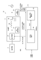
- FIG. 1 is a block diagram schematically showing a power conversion device according to an embodiment.
- the power conversion device 10 includes a main circuit section 12, a control device 14, a first measurement device 16, and a second measurement device 18.
- the main circuit unit 12 converts electric power.
- the control device 14 controls power conversion by the main circuit section 12 .
- the main circuit section 12 is connected to the power system 2 and the power supply device 4 .
- the power system 2 is an AC power system.
- the AC power of the power system 2 is, for example, three-phase AC power. However, the AC power of the power system 2 may be single-phase AC power or the like.
- the power supply device 4 is, for example, a power storage device using a storage battery or the like. The power supply device 4 outputs DC power to the main circuit section 12 .
- the main circuit unit 12 converts, for example, DC power input from the power supply device 4 into AC power corresponding to the power system 2, outputs the converted AC power to the power system 2, and receives input from the power system 2.
- the power supply device 4 is charged by converting the AC power into DC power. Thereby, the main circuit unit 12 connects the power supply device 4 with the power system 2 .
- the power supply device 4 is not limited to a power storage device, and may be, for example, a solar battery panel. In this case, the main circuit section 12 may not have the function of converting AC power input from the power system 2 into DC power.
- the power supply device 4 may be, for example, another power generator such as a wind power generator or a gas turbine power generator.
- the power input from the power supply device 4 to the main circuit unit 12 is not limited to DC power, and may be AC power.
- the main circuit unit 12 may be configured to convert the AC power input from the power supply device 4 into another AC power corresponding to the power system 2 .
- the power supply device 4 may be, for example, another power system different from the power system 2 .
- the main circuit unit 12 may be, for example, a frequency conversion device that connects two electric power systems with different frequencies.
- the conversion of power by the main circuit unit 12 is not limited to conversion from DC to AC, and may be any conversion that converts the power of the power supply device 4 into AC power compatible with the power system 2 .
- the main circuit section 12 has a power conversion section 20 and a filter circuit 22 .
- the power conversion unit 20 converts power.
- the power converter 20 has, for example, a plurality of switching elements, and performs power conversion by switching the plurality of switching elements.
- the power converter 20 has, for example, a plurality of switching elements connected in a three-phase bridge.
- the configuration of the power conversion unit 20 may be any configuration that can convert input power into AC power compatible with the power system 2 by switching a plurality of switching elements or the like.
- the filter circuit 22 is provided on the AC side of the power converter 20 .
- filter circuit 22 is provided between power converter 20 and power system 2 .
- the filter circuit 22 brings the AC power output from the power converter 20 closer to a sine wave.
- the filter circuit 22 brings the AC power output from the power conversion unit 20 closer to a sine wave by, for example, suppressing high-frequency components contained in the AC power output from the power conversion unit 20 .
- the filter circuit 22 has, for example, a reactor 24 connected in series with the AC output point of the power converter 20 and a capacitor 26 connected in parallel with the AC output point of the power converter 20 .
- a reactor 24 and a capacitor 26 are provided for each phase of the AC power output from the power converter 20 .
- the configuration of the filter circuit 22 is not limited to this, and may be any configuration capable of making the AC power output from the power converter 20 approximate a sine wave.
- the first measuring device 16 measures the phase voltages Va (INV), Vb (INV), and Vc (INV) of each phase of the AC power output from the power converter 20, and the line currents Ia (INV) and Ib of each phase. (INV) and Ic(INV) are measured, and the measurement results are input to the control device 14 .
- the second measuring device 18 measures the phase voltage Va (PCS), Vb (PCS), Vc (PCS) of each phase of the AC power output from the main circuit unit 12 (filter circuit 22), the line current Ia ( PCS), Ib (PCS), Ic (PCS), the active power P (PCS) at the output terminal of the main circuit section 12, and the reactive power Q (PCS) at the output terminal of the main circuit section 12 are measured, and the measurement results are Input to controller 14 .
- PCS phase voltage Va
- Vb PCS
- Vc PCS
- the control device 14 controls power conversion by the main circuit section 12 by controlling the operation of the power conversion section 20 . In other words, the control device 14 controls switching of the plurality of switching elements of the power converter 20 .
- the measurement results of the first measuring device 16 and the second measuring device 18 are input to the control device 14, and the active power command value and the reactive power command value of the AC power output from the main circuit unit 12 are input to a higher controller. and so on.
- the control device 14 performs power conversion based on the measurement results input from the first measuring device 16 and the second measuring device 18, and the active power command value and reactive power command value input from a higher controller or the like. It controls the operation of unit 20 .
- the control device 14 Based on the input measurement results, active power command value, and reactive power command value, the control device 14 outputs an instantaneous value voltage output command for each phase of the AC power output from the power conversion unit 20. Values Va(ref), Vb(ref), and Vc(ref) are calculated, and voltages corresponding to the calculated instantaneous voltage output command values Va(ref), Vb(ref), and Vc(ref) are supplied to the power conversion unit 20 The operation of the power conversion unit 20 is controlled so that the output is from .
- control device 14 controls the output voltage of the main circuit section 12 .
- the control device 14 performs voltage control operation of the main circuit section 12 .
- each measurement result is not limited to being directly input to the control device 14 from the first measuring device 16 and the second measuring device 18, and is input to the control device 14 via, for example, a higher-level controller. good too.
- the measured value of the active power P (PCS) at the output terminal of the main circuit section 12 and the measured value of the reactive power Q (PCS) at the output terminal of the main circuit section 12 are transmitted from the second measuring device 18 to the control device 14.
- phase voltage Va (PCS), Vb (PCS), Vc (PCS) of each phase, line current Ia (PCS), Ib (PCS), Ic (PCS) of each phase may be calculated in the control device 14 based on each measured value.
- the second measuring device 18 does not necessarily have to measure the active power P(PCS) and the reactive power Q(PCS).
- the control device 14 has a command value calculation section 30 and an overcurrent suppression control section 32 .
- the active power command value and the reactive power command value input from a host controller or the like are input to the command value calculation unit 30, and the active power P (PCS) and the reactive power Q measured by the second measuring device 18 are input. Each measured value of (PCS) is input.
- the command value calculation unit 30 calculates the phase voltage phase command value ⁇ of the AC power output from the main circuit unit 12 based on the active power command value and the measured value of the active power P(PCS). Then, the command value calculation unit 30 calculates the phase voltage amplitude command value
- the command value calculator 30 inputs the calculated phase voltage phase command value ⁇ and phase voltage amplitude command value
- a well-known calculation method may be used to calculate the phase voltage phase command value ⁇ and the phase voltage amplitude command value
- the overcurrent suppression control unit 32 controls the phase voltage phase command value ⁇ , phase voltage amplitude command value
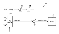
- FIG. 2 is a block diagram schematically showing an overcurrent suppression controller according to the embodiment.
- the overcurrent suppression control unit 32 includes a dq inverse transform unit 40, an overcurrent detector 42, a proportional calculator 44, a subtractor 46, and a control signal generator 48. .
- are input to the dq inverse transform unit 40 .
- is input to the dq inverse transform section 40 as a voltage signal of the d-axis component.
- “0” is input to the dq inverse transform unit 40 as the voltage signal of the q-axis component.
- the dq inverse transform unit 40 performs dq inverse transform (inverse park transform) on the input phase voltage phase command value ⁇ , phase voltage amplitude command value
- the dq inverse transform unit 40 based on the phase voltage phase command value ⁇ and the phase voltage amplitude command value
- Measured values of the line currents Ia (INV), Ib (INV), and Ic (INV) of each phase of the AC power of the power converter 20 measured by the first measuring device 16 are input to the overcurrent detector 42 . be.
- the overcurrent detector 42 detects the magnitude of the overcurrent of the line currents Ia (INV), Ib (INV), and Ic (INV) of the power converter 20 .
- the overcurrent detector 42 for example, sets a dead band for the measured values of the line currents Ia (INV), Ib (INV), and Ic (INV) of the power converter 20, thereby detecting components exceeding the dead band. Detected as the magnitude of the current.
- the overcurrent detector 42 sets upper and lower limits for the line currents Ia (INV), Ib (INV), and Ic (INV) of the power converter 20 .
- the upper limit is, in other words, the positive overcurrent threshold.
- the lower limit value is, in other words, the negative overcurrent threshold.
- the overcurrent detector 42 sets a dead zone between the upper limit value and the lower limit value.
- the overcurrent detector 42 detects the line currents Ia (INV), Ib (INV), Ic (INV ), the value exceeding the upper limit value is detected as the magnitude of the overcurrent.
- the overcurrent detector 42 detects the line currents Ia (INV), Ib (INV), Ic (INV ), the value exceeding the lower limit value is detected as the magnitude of the overcurrent.
- the overcurrent detector 42 outputs "0" when the measured values of the line currents Ia (INV), Ib (INV), and Ic (INV) are within the range between the upper limit and the lower limit. Detected as the magnitude of overcurrent.
- the overcurrent detector 42 inputs the detected overcurrent magnitudes of the line currents Ia (INV), Ib (INV), and Ic (INV) to the proportional calculator 44 .
- the proportional calculator 44 multiplies the magnitude of the overcurrent input from the overcurrent detector 42 by a proportionality constant Kp to obtain a correction value for the instantaneous voltage of each phase of the AC power of the main circuit unit 12. Calculate. More specifically, the correction values are for reducing the magnitudes of the line currents Ia (INV), Ib (INV), and Ic (INV) of the power converter 20 by the magnitudes of the detected overcurrents. It is the correction value of the instantaneous value voltage of each phase of the AC power of the main circuit unit 12 .
- the proportional calculator 44 inputs the calculated correction value to the subtractor 46 .
- the subtractor 46 subtracts the correction value input from the proportional calculator 44 from the command values Va, Vb, and Vc of the instantaneous voltage values of the respective phases of the AC power of the main circuit unit 12 input from the dq inverse transform unit 40. . That is, the subtractor 46 suppresses the instantaneous voltage command values Va, Vb, and Vc in accordance with the detected overcurrent component (component exceeding the current dead band). As a result, the subtractor 46 prevents an overcurrent from occurring in the main circuit section 12 due to a potential difference instantaneously generated due to a sudden change in the system voltage of the electric power system 2 or the like.
- the subtractor 46 sets the subtraction result to the instantaneous voltage output command values Va (ref), Vb (ref), and Vc (ref) of each phase of the AC power of the power conversion unit 20, and calculates the instantaneous voltage output of each phase.
- the command values Va(ref), Vb(ref), and Vc(ref) are input to the control signal generator 48 .
- the control signal generation unit 48 outputs from the power conversion unit 20 voltages corresponding to the instantaneous voltage output command values Va(ref), Vb(ref), and Vc(ref) of each phase input from the subtractor 46. and inputs the generated control signal to the power converter 20 . Thereby, the control signal generation unit 48 causes the power conversion unit 20 to output voltages corresponding to the instantaneous voltage output command values Va(ref), Vb(ref), and Vc(ref) of each phase.
- the control signal generation unit 48 performs sine wave pulse width modulation control based on, for example, the instantaneous voltage output command values Va (ref), Vb (ref), and Vc (ref) of each phase, so that the power conversion unit A control signal is generated for controlling the switching of each of the 20 switching elements.
- the configuration of the control signal generation unit 48 is not limited to this, and the voltage corresponding to the instantaneous voltage output command values Va (ref), Vb (ref), and Vc (ref) of each phase is generated from the power conversion unit 20. Any configuration capable of generating a control signal for output may be used.
- control signal generation unit 48 is provided on the main circuit unit 12 side, and the instantaneous value voltage output command values Va (ref), Vb ( ref) and Vc(ref) may be input, and a control signal may be generated on the main circuit section 12 side.
- the overcurrent suppression controller 32 does not necessarily have to have the control signal generator 48 .
- the overcurrent suppression control unit 32 provides the phase voltage phase command value ⁇ , the phase voltage amplitude command value
- the first measuring device 16 does not necessarily have to measure the phase voltages Va (INV), Vb (INV), and Vc (INV) of each phase of the AC power output from the power converter 20 .
- the first measuring device 16 may be configured to measure only the line currents Ia (INV), Ib (INV), and Ic (INV) of each phase of the AC power output from the power converter 20 .
- the second measuring device 18 does not necessarily measure the phase voltages Va (PCS), Vb (PCS), and Vc (PCS) of each phase of the AC power output from the main circuit section 12, and the line current of each phase. It is not necessary to input the measurement results of Ia (PCS), Ib (PCS), and Ic (PCS) to the control device 14 .
- the second measuring device 18 may be configured to input only the measurement results of the active power P (PCS) at the output end of the main circuit section 12 and the reactive power Q (PCS) at the output end of the main circuit section 12 to the control device 14. good.
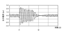
- FIG. 3 is a graph that schematically represents an example of the operation of the power converter according to the embodiment.
- FIG. 4 is a graph schematically showing an example of the operation of a reference power converter.
- FIG. 4 schematically shows an example of the operation of a reference power conversion device in which the control device 14 does not have the overcurrent suppression control section 32 . 3 and 4, the horizontal axis represents time (seconds), and the vertical axis represents output current (pu: per unit) based on the rated output of the main circuit section 12.
- FIG. 3 is a graph that schematically represents an example of the operation of the power converter according to the embodiment.
- FIG. 4 is a graph schematically showing an example of the operation of a reference power converter.
- FIG. 4 schematically shows an example of the operation of a reference power conversion device in which the control device 14 does not have the overcurrent suppression control section 32 . 3 and 4, the horizontal axis represents time (seconds), and the vertical axis represents output current (pu: per unit) based on the rated output
- FIG. 3 shows an example of the operation of the power conversion device 10 when a three-line ground fault with a fault point residual voltage of approximately 50% occurs between times t1 and t2.
- FIG. 4 shows an example of the operation of a reference power converter in a similar case.
- the upper limit value of the dead band in the overcurrent detector 42 of the overcurrent suppression control unit 32 is +1.2 (pu), and the lower limit value of the dead band is -1.2 (pu ).
- the output current of the main circuit unit 12 can be suppressed to about ⁇ 1.2 (pu). ing.
- generation of overcurrent can be suppressed even when an accident occurs, compared to the reference power conversion device that does not have the overcurrent suppression control unit 32.
- the control device 14 has the overcurrent suppression control section 32 .
- the overcurrent suppression control section 32 it is possible to suppress the occurrence of overcurrent even when the voltage control operation is performed. For example, when an instantaneous potential difference occurs due to a sudden change in the system voltage, etc., an overcurrent occurs in the main circuit unit 12, and parts inside the main circuit unit 12 such as the switching elements of the power conversion unit 20 malfunction. You can prevent it from happening.
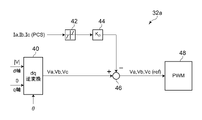
- FIG. 5 is a block diagram schematically showing a modification of the overcurrent suppression control section according to the embodiment. It should be noted that the same reference numerals are given to the parts that are substantially the same as those of the above-described embodiment in terms of function and configuration, and detailed description thereof will be omitted.
- the input of the overcurrent detector 42 is the line current Ia (PCS ), Ib(PCS), and Ic(PCS).
- the overcurrent suppression control unit 32a detects the magnitude of the overcurrent of the line currents Ia (PCS), Ib (PCS), and Ic (PCS) of the main circuit unit 12, and calculates an instantaneous value according to the detected overcurrent component. By suppressing the voltage command values Va, Vb, and Vc, overcurrent at the output terminal of the main circuit section 12 is suppressed.
- the overcurrent suppression control unit 32a controls the phase voltage phase command value ⁇ , the phase voltage amplitude command value
- the power converter 10 does not necessarily have to include the first measuring device 16 .
- the power converter 10 may be configured to include only the second measuring device 18 .
- FIG. 6 is a block diagram schematically showing a modification of the overcurrent suppression control section according to the embodiment.
- the overcurrent suppression control unit 32b includes a dq inverse transform unit 50, a first subtractor 51, a first proportional calculator 52, a limiter 53, a second subtractor 54, and a It has a 2-proportional calculator 55 , an adder 56 and a control signal generator 57 .
- the dq inverse transform unit 50 is the same as the dq inverse transform unit 40 described with reference to FIG. 2, so detailed description will be omitted.
- the dq inverse transform unit 50 inputs the calculated instantaneous voltage command values Va, Vb, and Vc to the first subtractor 51 .
- the command values Va, Vb, and Vc of the instantaneous value voltage of each phase are input to the first subtractor 51 from the dq inverse transforming unit 50, and the AC power of the main circuit unit 12 measured by the second measuring device 18 Measured values of phase voltages Va (PCS), Vb (PCS), and Vc (PCS) of each phase are inputted.
- the first subtractor 51 subtracts the measured values of the phase voltages Va (PCS), Vb (PCS), and Vc (PCS) of the respective phases from the command values Va, Vb, and Vc of the instantaneous voltage values of the respective phases. Differences between the command values Va, Vb, and Vc of the instantaneous value voltages of the phases and the measured values of the phase voltages Va (PCS), Vb (PCS), and Vc (PCS) of the respective phases are calculated.
- the first proportional calculator 52 multiplies the difference calculated by the first subtractor 51 by the first proportionality constant Kp1 to obtain the phase voltages Va (PCS), Vb (PCS), and Vc (PCS) of each phase.
- the first proportional calculator 52 inputs the calculated command value to the limiter 53 .
- the limiter 53 controls the phase line currents Ia (PCS), Ib ( PCS) and Ic (PCS) command values are limited to the upper limit values, and the input command values of the line currents Ia (PCS), Ib (PCS), and Ic (PCS) of each phase are equal to or less than the lower limit values First, the command values of the line currents Ia (PCS), Ib (PCS), and Ic (PCS) of each phase are limited to lower limits.
- the limiter 53 When each input command value is greater than the lower limit value and less than the upper limit value, the limiter 53 inputs each input command value as it is to the second subtractor 54 .
- the limiter 53 limits each command value to the lower limit value when each input command value is equal to or less than the lower limit value, and inputs each command value after the limit to the second subtractor 54 .
- the limiter 53 limits each command value to the upper limit value, and inputs each command value after the limit to the second subtractor 54 .
- the limiter 53 prevents overcurrent from occurring in the main circuit section 12 due to a potential difference instantaneously generated due to a sudden change in the system voltage of the electric power system 2 or the like.
- the command values of the line currents Ia (PCS), Ib (PCS), and Ic (PCS) of each phase are inputted from the limiter 53 to the second subtractor 54, and the main circuit Measured values of the line currents Ia (PCS), Ib (PCS), and Ic (PCS) of each phase of the AC power of the unit 12 are input.
- a second subtractor 54 calculates line currents Ia (PCS), Ib (PCS), and Ic (PCS) of the phases from command values of the line currents Ia (PCS), Ib (PCS), and Ic (PCS) of the phases. By subtracting the measured values, the command values of the line currents Ia (PCS), Ib (PCS), and Ic (PCS) of each phase and the line currents of Ia (PCS), Ib (PCS), and Ic (PCS) of each phase are obtained. Calculate the difference from the measured value.
- the second proportional calculator 55 multiplies the difference calculated by the second subtractor 54 by the second proportionality constant Kp2 to obtain line currents Ia (PCS), Ib (PCS), and Ic (PCS) of each phase.
- a correction value for outputting a current corresponding to the command value from the power conversion unit 20 is calculated. More specifically, the correction values are correction values for the phase voltages Va (PCS), Vb (PCS), and Vc (PCS) of the AC power output from the main circuit section 12 .
- the second proportional calculator 55 inputs the calculated correction value to the adder 56 .
- the adder 56 receives the correction value from the second proportional calculator 55 and the phase voltages Va (PCS), Vb ( PCS) and Vc (PCS) are input.
- the adder 56 adds the correction value to the measured values of the phase voltages Va (PCS), Vb (PCS), and Vc (PCS) of each phase. Thereby, the adder 56 calculates the instantaneous voltage output command values Va(ref), Vb(ref), and Vc(ref) for each phase of the AC power output from the power converter 20 .
- the adder 56 inputs the calculated instantaneous voltage output command values Va(ref), Vb(ref), and Vc(ref) for each phase to the control signal generator 57 .
- the control signal generator 57 is the same as the control signal generator 48 described with reference to FIG. 2, so detailed description thereof will be omitted.
- phase voltage phase command value ⁇ phase voltage amplitude command value
- the instantaneous voltage output command values Va (ref), Vb (ref), and Vc are calculated so as to suppress overcurrent at the output end of the main circuit section 12. (ref) is calculated.
- the limiter 53 sets the command values of the line currents Ia (PCS), Ib (PCS), and Ic (PCS) of the phases of the AC power output from the main circuit unit 12 to lower and upper limits.
- the instantaneous voltage output command values Va(ref), Vb(ref), and Vc(ref) are calculated so as to suppress overcurrent at the output end of the main circuit unit 12 by limiting between be able to.
- the overcurrent suppression control unit 32b controls the phase voltage phase command value ⁇ , the phase voltage amplitude command value
- the instantaneous voltage output command values Va(ref), Vb(ref), and Vc(ref) may be calculated so as to suppress overcurrent at the output terminal of the unit 12 .
- the power converter 10 does not necessarily have to include the first measuring device 16 .
- the power converter 10 may be configured to include only the second measuring device 18 .
- FIG. 7 is a block diagram schematically showing a modification of the overcurrent suppression control section according to the embodiment.
- the overcurrent suppression control unit 32c includes a voltage estimation unit 60, a dq inverse transform unit 61, a first subtractor 62, a first proportional calculator 63, and a first adder 64. , a limiter 65 , a second subtractor 66 , a second proportional calculator 67 , a second adder 68 , and a control signal generator 69 .
- the voltage estimation unit 60 estimates each phase of the AC power of the main circuit unit 12 based on the measured values of the line currents Ia (INV), Ib (INV), and Ic (INV) of each phase of the AC power of the power conversion unit 20. phase voltages Va (PCS), Vb (PCS), and Vc (PCS) are estimated.
- the voltage estimation unit 60 stores the phase voltage phase command value ⁇ calculated by the command value calculation unit 30 and the line current Ia ( INV), Ib(INV), and Ic(INV) are input.
- the voltage estimator 60 determines the AC voltage of the main circuit unit 12. Estimated values Va (virtual), Vb (virtual), Vc (virtual) of phase voltages Va (PCS), Vb (PCS), Vc (PCS) of each phase of electric power are calculated.
- the voltage estimator 60 has, for example, a dq transform unit 80, a coefficient calculator 81, a dq inverse transform unit 82, and a proportional control calculator 83.
- the dq conversion unit 80 receives the phase voltage phase command value ⁇ and the measured values of the line currents Ia (INV), Ib (INV), and Ic (INV) of each phase of the AC power of the power conversion unit 20. be.
- the dq conversion unit 80 performs dq conversion (park conversion) on the input phase voltage phase command value ⁇ and the measured values of the line currents Ia (INV), Ib (INV), and Ic (INV) of each phase. , based on the phase voltage phase command value ⁇ and the measured values of the line currents Ia (INV), Ib (INV), and Ic (INV) of each phase, the line current Ia (INV) of each phase , Ib(INV), and Ic(INV), and a current signal Iq representing the q-axis components of the line currents Ia(INV), Ib(INV), and Ic(INV) of each phase. , is calculated.
- the dq transform unit 80 inputs the calculated current signal Id to the dq inverse transform unit 82 and inputs the calculated current signal Iq to the coefficient calculator 81 .
- the coefficient calculator 81 multiplies the input current signal Iq by a coefficient "-1", and inputs the current signal -Iq after the calculation to the dq inverse transform unit .
- the DQ voltage is proportional to the DQ current phase-shifted by 90 degrees.
- a voltage signal Vq representing the q-axis components of the phase voltages Va (PCS), Vb (PCS), and Vc (PCS) of each phase of the AC power of the main circuit unit 12 corresponds to the line of each phase of the AC power of the power conversion unit 20. It can be estimated by the current signal Id representing the d-axis components of the currents Ia (INV), Ib (INV), and Ic (INV).
- the voltage signal Vd representing the d-axis component of the phase voltages Va (PCS), Vb (PCS), and Vc (PCS) of each phase of the AC power of the main circuit unit 12 corresponds to each phase of the AC power of the power converter 20.
- the current signal -Iq obtained by multiplying the current signal Iq representing the q-axis component of the line currents Ia (INV), Ib (INV), and Ic (INV) of , by "-1".
- the dq transform unit 80 inputs the calculated current signal Id to the dq inverse transform unit 82 as the voltage signal Vq.
- the coefficient calculator 81 inputs the calculated current signal -Iq to the dq inverse transform unit 82 as the voltage signal Vd.
- the voltage signal Vq (current signal Id) and the voltage signal Vd (current signal -Iq) are input to the dq inverse transforming unit 82, and the phase voltage phase command value ⁇ is also input.
- the dq inverse transform unit 82 performs dq inverse transform (inverse park transform) on the input phase voltage phase command value ⁇ and the voltage signals Vq and Vd, thereby converting three phases based on the voltage signals Vq and Vd. Calculate the instantaneous voltage.
- the dq inverse transformer 82 inputs the calculated three-phase instantaneous voltages to the proportional control calculator 83 .
- the proportional control calculator 83 performs a proportional calculation on the input instantaneous three-phase voltages, thereby controlling each phase of the AC power of the main circuit unit 12 based on the input instantaneous three-phase voltages. Estimated values Va(virtual), Vb(virtual), Vc(virtual) of phase voltages Va(PCS), Vb(PCS), Vc(PCS) are calculated.
- the configuration of the voltage estimation unit 60 is not limited to the above.
- the configuration of the voltage estimator 60 is such that the phase voltage Va (PCS ), Vb(PCS), and Vc(PCS) estimated values Va(virtual), Vb(virtual), and Vc(virtual).
- the dq inverse transform unit 61 is the same as the dq inverse transform unit 40 described with reference to FIG. 2, so detailed description is omitted.
- the dq inverse transform unit 61 inputs the calculated instantaneous voltage command values Va, Vb, and Vc to the first subtractor 62 .
- the command values Va, Vb, and Vc of the instantaneous value voltage of each phase are input to the first subtractor 62 from the dq inverse transforming section 61, and the AC power of the main circuit section 12 calculated by the voltage estimating section 60 is input to the first subtractor 62.
- Estimated values Va(virtual), Vb(virtual) and Vc(virtual) of phase voltages Va(PCS), Vb(PCS) and Vc(PCS) of respective phases are inputted.
- a first subtractor 62 calculates estimated values Va (virtual), Vb By subtracting (virtual) and Vc (virtual), the command values Va, Vb, and Vc of the instantaneous value voltage of each phase and the estimated values of the phase voltages Va (PCS), Vb (PCS), and Vc (PCS) of each phase Differences from Va (virtual), Vb (virtual), and Vc (virtual) are calculated.
- the first proportional calculator 63 multiplies the difference calculated by the first subtractor 62 by the first proportionality constant Kp1 to obtain the phase voltages Va (PCS), Vb (PCS), and Vc (PCS) of each phase. Correction values are calculated to approximate the command values Va, Vb, and Vc of the instantaneous value voltages of the respective phases. More specifically, the correction values are correction values for the phase line currents Ia (INV), Ib (INV), and Ic (INV) of the AC power of the power converter 20 . The first proportional calculator 63 inputs the calculated correction value to the first adder 64 .
- the correction value is input from the first proportional calculator 63 to the first adder 64, and the line current Ia (INV) of each phase of the AC power of the power conversion unit 20 measured by the first measuring device 16, Measured values of Ib(INV) and Ic(INV) are input.
- the first adder 64 adds a correction value to the measured values of the line currents Ia (INV), Ib (INV), and Ic (INV) of each phase.
- the first adder 64 converts the phase voltages Va (PCS), Vb (PCS), and Vc (PCS) of the phases of the AC power output from the main circuit unit 12 into the command values of the instantaneous voltages of the phases.
- the command values of the line currents Ia (INV), Ib (INV), and Ic (INV) of each phase of the power converter 20 required to approach Va, Vb, and Vc are calculated.
- the first adder 64 inputs the calculated command values of the line currents Ia (INV), Ib (INV), and Ic (INV) of each phase to the limiter 65 .
- the limiter 65 controls the phase line currents Ia (INV), Ib ( (INV) and Ic (INV) are limited to the upper limit, and the input command values for the line currents Ia (INV), Ib (INV), and Ic (INV) of each phase are below the lower limit. First, the command values of the line currents Ia (INV), Ib (INV), and Ic (INV) of each phase are limited to lower limits.
- the limiter 65 When each input command value is greater than the lower limit value and less than the upper limit value, the limiter 65 inputs each input command value as it is to the second subtractor 66 .
- the limiter 65 limits each command value to the lower limit value when each input command value is equal to or less than the lower limit value, and inputs each command value after the limit to the second subtractor 66 .
- the limiter 65 limits each command value to the upper limit value and inputs each command value after the limit to the second subtractor 66 .
- the limiter 65 prevents an overcurrent from occurring in the main circuit section 12 due to a potential difference instantaneously generated due to a sudden change in the system voltage of the electric power system 2 or the like.
- the command values of the line currents Ia (INV), Ib (INV), and Ic (INV) of each phase are input from the limiter 65 to the second subtractor 66, and the power conversion measured by the first measuring device 16 is input. Measured values of the line currents Ia (INV), Ib (INV), and Ic (INV) of each phase of the unit 20 are input.
- a second subtractor 66 calculates line currents Ia (INV), Ib (INV), and Ic (INV) of each phase from command values of line currents Ia (INV), Ib (INV), and Ic (INV) of each phase. By subtracting the measured values, the command values of the line currents Ia (INV), Ib (INV), and Ic (INV) of each phase and the line currents Ia (INV), Ib (INV), and Ic (INV) of each phase are obtained. Calculate the difference from the measured value.
- the second proportional calculator 67 multiplies the difference calculated by the second subtractor 66 by the second proportionality constant Kp2 to obtain line currents Ia (INV), Ib (INV), and Ic (INV) of each phase.
- a correction value for outputting a current corresponding to the command value from the power conversion unit 20 is calculated. More specifically, the correction values are correction values for the phase voltages Va (PCS), Vb (PCS), and Vc (PCS) of the AC power output from the main circuit section 12 .
- the second proportional calculator 67 inputs the calculated correction value to the second adder 68 .
- the correction value is input from the second proportional calculator 67 to the second adder 68, and the phase voltages Va (PCS) and Vb of the AC power of the main circuit section 12 calculated by the voltage estimating section 60 are calculated.
- Estimated values Va (virtual), Vb (virtual), and Vc (virtual) of (PCS) and Vc (PCS) are input.
- the second adder 68 adds a correction value to the estimated values Va(virtual), Vb(virtual) and Vc(virtual) of the phase voltages Va(PCS), Vb(PCS) and Vc(PCS) of each phase. Thereby, the second adder 68 calculates the instantaneous voltage output command values Va(ref), Vb(ref), and Vc(ref) for each phase of the AC power output from the power converter 20 .
- the second adder 68 inputs the calculated instantaneous voltage output command values Va(ref), Vb(ref), and Vc(ref) for each phase to the control signal generator 69 .
- the control signal generator 69 is the same as the control signal generator 48 described with reference to FIG. 2, so detailed description thereof will be omitted.
- the overcurrent suppression control unit 32c controls the phase voltage phase command value ⁇ , the phase voltage amplitude command value
- Estimated values Va (virtual), Vb (virtual), and Vc (virtual) of Va (PCS), Vb (PCS), and Vc (PCS) are used to suppress overcurrent at the output terminal of the main circuit unit 12. Then, the instantaneous voltage output command values Va(ref), Vb(ref) and Vc(ref) are calculated.
- the limiter 65 sets the command values of the line currents Ia (INV), Ib (INV), and Ic (INV) of each phase of the AC power output from the power conversion unit 20 to the lower limit value and the upper limit value.
- the instantaneous voltage output command values Va(ref), Vb(ref), and Vc(ref) are calculated so as to suppress overcurrent at the output end of the main circuit unit 12 by limiting between be able to.
- the overcurrent suppression control unit 32c controls the phase voltage phase command value ⁇ , the phase voltage amplitude command value
- the instantaneous voltage output command values Va(ref), Vb(ref), and Vc(ref) may be calculated so as to suppress overcurrent at .
- the first measuring device 16 does not necessarily have to measure the phase voltages Va (INV), Vb (INV), and Vc (INV) of each phase of the AC power output from the power converter 20 .
- the first measuring device 16 may be configured to measure only the line currents Ia (INV), Ib (INV), and Ic (INV) of each phase of the AC power output from the power converter 20 .
- the second measuring device 18 does not necessarily measure the phase voltages Va (PCS), Vb (PCS), and Vc (PCS) of each phase of the AC power output from the main circuit section 12, and the line current of each phase. It is not necessary to input the measurement results of Ia (PCS), Ib (PCS), and Ic (PCS) to the control device 14 .
- the second measuring device 18 may be configured to input only the measurement results of the active power P (PCS) at the output end of the main circuit section 12 and the reactive power Q (PCS) at the output end of the main circuit section 12 to the control device 14. good.
- the configuration of the overcurrent suppression control unit is not limited to the above, but includes phase voltage phase command value ⁇ , phase voltage amplitude command value
Landscapes
- Engineering & Computer Science (AREA)
- Power Engineering (AREA)
- Inverter Devices (AREA)
Abstract
Description
なお、図面は模式的または概念的なものであり、各部分の厚みと幅との関係、部分間の大きさの比率などは、必ずしも現実のものと同一とは限らない。また、同じ部分を表す場合であっても、図面により互いの寸法や比率が異なって表される場合もある。
なお、本願明細書と各図において、既出の図に関して前述したものと同様の要素には同一の符号を付して詳細な説明は適宜省略する。
図1に表したように、電力変換装置10は、主回路部12と、制御装置14と、第1計測装置16と、第2計測装置18と、を備える。主回路部12は、電力の変換を行う。制御装置14は、主回路部12による電力の変換を制御する。
図2に表したように、過電流抑制制御部32は、dq逆変換部40と、過電流検出器42と、比例演算器44と、減算器46と、制御信号生成部48と、を有する。
図4は、参考の電力変換装置の動作の一例を模式的に表すグラフである。
図4は、制御装置14が過電流抑制制御部32を有していない参考の電力変換装置の動作の一例を模式的に表す。
図3及び図4において、横軸は、時間(秒)であり、縦軸は、主回路部12の定格出力を基準とした出力電流(pu:per unit)である。
なお、上記実施形態と機能・構成上実質的に同じものについては、同符号を付し、詳細な説明は省略する。
図5に表したように、過電流抑制制御部32aでは、過電流検出器42の入力が、第2計測装置18によって測定された主回路部12の交流電力の各相の線電流Ia(PCS)、Ib(PCS)、Ic(PCS)の測定値に置き換えられている。
図6に表したように、過電流抑制制御部32bは、dq逆変換部50と、第1減算器51と、第1比例演算器52と、リミッタ53と、第2減算器54と、第2比例演算器55と、加算器56と、制御信号生成部57と、を有する。
図7に表したように、過電流抑制制御部32cは、電圧推定部60と、dq逆変換部61と、第1減算器62と、第1比例演算器63と、第1加算器64と、リミッタ65と、第2減算器66と、第2比例演算器67と、第2加算器68と、制御信号生成部69と、を有する。
Claims (7)
- 入力された電力を交流電力に変換する電力変換部と、前記電力変換部から出力された前記交流電力を正弦波に近付けるフィルタ回路と、を有する主回路部と、
前記電力変換部の動作を制御することにより、前記主回路部による電力の変換を制御する制御装置と、
を備え、
前記制御装置は、
有効電力指令値及び無効電力指令値が入力されるとともに、前記主回路部の出力端の前記有効電力及び前記無効電力の各測定値が入力され、前記有効電力指令値と前記有効電力の測定値とを基に、前記主回路部から出力する前記交流電力の相電圧位相指令値を演算し、前記無効電力指令値と前記無効電力の測定値とを基に、前記主回路部から出力する前記交流電力の相電圧振幅指令値を演算する指令値演算部と、
前記相電圧位相指令値、前記相電圧振幅指令値、前記電力変換部の前記交流電力の相電圧及び線電流の各測定値、及び前記主回路部の前記交流電力の相電圧及び線電流の各測定値の各入力情報のいずれかを用いて、前記主回路部の出力端での過電流を抑制するように、前記電力変換部から出力する前記交流電力の各相の瞬時値電圧出力指令値を演算する過電流抑制制御部と、
を有し、演算した前記瞬時値電圧出力指令値に応じた電圧が前記電力変換部から出力されるように、前記電力変換部の動作を制御する電力変換装置。 - 前記過電流抑制制御部は、
前記相電圧位相指令値及び前記相電圧振幅指令値を基に、dq逆変換を行うことにより、前記主回路部から出力する前記交流電力の各相の瞬時値電圧の指令値を演算するdq逆変換部と、
前記電力変換部の前記交流電力の線電流の過電流の大きさを検出する過電流検出器と、
前記過電流検出器から入力された過電流の大きさに対して比例定数を乗算することにより、前記主回路部の前記交流電力の各相の瞬時値電圧の補正値を演算する比例演算器と、
前記比例演算器から入力された前記補正値を前記dq逆変換部から入力された前記主回路部の前記交流電力の各相の瞬時値電圧の指令値から減算することにより、減算結果を前記電力変換部の前記交流電力の前記各相の瞬時値電圧出力指令値として演算する減算器と、
を有する請求項1記載の電力変換装置。 - 前記過電流抑制制御部は、
前記相電圧位相指令値及び前記相電圧振幅指令値を基に、dq逆変換を行うことにより、前記主回路部から出力する前記交流電力の各相の瞬時値電圧の指令値を演算するdq逆変換部と、
前記主回路部の前記交流電力の線電流の過電流の大きさを検出する過電流検出器と、
前記過電流検出器から入力された過電流の大きさに対して比例定数を乗算することにより、前記主回路部の前記交流電力の各相の瞬時値電圧の補正値を演算する比例演算器と、
前記比例演算器から入力された前記補正値を前記dq逆変換部から入力された前記主回路部の前記交流電力の各相の瞬時値電圧の指令値から減算することにより、減算結果を前記電力変換部の前記交流電力の前記各相の瞬時値電圧出力指令値として演算する減算器と、
を有する請求項1記載の電力変換装置。 - 前記過電流抑制制御部は、
前記相電圧位相指令値及び前記相電圧振幅指令値を基に、dq逆変換を行うことにより、前記主回路部から出力する前記交流電力の各相の瞬時値電圧の指令値を演算するdq逆変換部と、
演算された前記各相の瞬時値電圧の指令値から前記主回路部の交流電力の各相の相電圧の測定値を差し引くことにより、前記各相の瞬時値電圧の指令値と前記各相の相電圧の測定値との差分を演算する第1減算器と、
前記第1減算器によって演算された前記差分に第1比例定数を乗算することにより、前記主回路部の交流電力の前記各相の相電圧を、演算された前記各相の瞬時値電圧の指令値に近付けるための、前記主回路部から出力される前記交流電力の各相の線電流の指令値を演算する第1比例演算器と、
前記各相の線電流の指令値が上限値以上である場合に、前記各相の線電流の指令値を前記上限値に制限するとともに、前記各相の線電流の指令値が下限値以下である場合に、前記各相の線電流の指令値を前記下限値に制限するリミッタと、
前記リミッタから入力された前記各相の線電流の指令値から前記主回路部の前記交流電力の各相の線電流Iaの測定値を差し引くことにより、前記各相の線電流の指令値と前記各相の線電流の測定値との差分を演算する第2減算器と、
前記第2減算器によって演算された前記差分に第2比例定数を乗算することにより、前記各相の線電流Iaの指令値に応じた電流を前記電力変換部から出力するための補正値を演算する第2比例演算器と、
前記主回路部の前記交流電力の前記各相の相電圧の測定値に前記補正値を加算することにより、前記電力変換部から出力する前記交流電力の前記各相の瞬時値電圧出力指令値を演算する加算器と、
を有する請求項1記載の電力変換装置。 - 前記過電流抑制制御部は、
前記電力変換部の前記交流電力の各相の線電流の測定値を基に、前記主回路部の前記交流電力の各相の相電圧の推定値を演算する電圧推定部と、
前記相電圧位相指令値及び前記相電圧振幅指令値を基に、dq逆変換を行うことにより、前記主回路部から出力する前記交流電力の各相の瞬時値電圧の指令値を演算するdq逆変換部と、
前記各相の瞬時値電圧の指令値から前記各相の相電圧の推定値を差し引くことにより、前記各相の瞬時値電圧の指令値と前記各相の相電圧の推定値との差分を演算する第1減算器と、
前記第1減算器によって演算された前記差分に第1比例定数を乗算することにより、前記主回路部の前記交流電力の各相の相電圧を前記各相の瞬時値電圧の指令値に近付けるための補正値を演算する第1比例演算器と、
前記電力変換部の前記交流電力の各相の線電流の測定値に前記第1比例演算器で演算された前記補正値を加算することにより、前記主回路部から出力される前記交流電力の各相の相電圧を前記各相の瞬時値電圧の指令値に近付けるために必要な前記電力変換部の前記交流電力の各相の線電流の指令値を演算する第1加算器と、
前記各相の線電流の指令値が上限値以上である場合に、前記各相の線電流の指令値を前記上限値に制限するとともに、前記各相の線電流の指令値が下限値以下である場合に、前記各相の線電流の指令値を前記下限値に制限するリミッタと、
前記リミッタから入力された前記各相の線電流の指令値から前記電力変換部の前記交流電力の各相の線電流の測定値を差し引くことにより、前記各相の線電流の指令値と前記各相の線電流の測定値との差分を演算する第2減算器と、
前記第2減算器によって演算された前記差分に第2比例定数を乗算することにより、前記各相の線電流の指令値に応じた電流を前記電力変換部から出力するための補正値を演算する第2比例演算器と、
前記各相の相電圧の推定値に前記第2比例演算器で演算された前記補正値を加算することにより、前記電力変換部から出力する前記交流電力の前記各相の瞬時値電圧出力指令値を演算する第2加算器と、
を有する請求項1記載の電力変換装置。 - 前記電圧推定部は、
前記相電圧位相指令値と、前記電力変換部の前記交流電力の各相の線電流の測定値と、に対してdq変換を行うことにより、前記相電圧位相指令値と、前記各相の線電流の測定値と、を基に、前記各相の線電流のd軸成分を表す電流信号と、前記各相の線電流のq軸成分を表す電流信号と、を演算する変換部と、
前記q軸成分を表す電流信号に-1を乗算する演算を行う係数演算器と、
前記相電圧位相指令値、前記d軸成分を表す電流信号、及び前記係数演算器で演算された後の前記q軸成分を表す電流信号に対してdq逆変換を行うことにより、前記d軸成分を表す電流信号及び前記q軸成分を表す電流信号を基に、三相の瞬時値電圧を演算する逆変換部と、
前記三相の瞬時値電圧に対して比例演算を行うことにより、前記三相の瞬時値電圧を基に、前記主回路部の前記交流電力の前記各相の相電圧の推定値を演算する比例制御演算器と、
を有する請求項5記載の電力変換装置。 - 入力された電力を交流電力に変換する電力変換部と、前記電力変換部から出力された前記交流電力を正弦波に近付けるフィルタ回路と、を有する主回路部を備えた電力変換装置に用いられ、前記電力変換部の動作を制御することにより、前記主回路部による電力の変換を制御する制御装置であって、
有効電力指令値及び無効電力指令値が入力されるとともに、前記主回路部の出力端の有効電力及び無効電力の各測定値が入力され、前記有効電力指令値と前記有効電力の測定値とを基に、前記主回路部から出力する前記交流電力の相電圧位相指令値を演算し、前記無効電力指令値と前記無効電力の測定値とを基に、前記主回路部から出力する前記交流電力の相電圧振幅指令値を演算する指令値演算部と、
前記相電圧位相指令値、前記相電圧振幅指令値、前記電力変換部の前記交流電力の相電圧及び線電流の各測定値、及び前記主回路部の前記交流電力の相電圧及び線電流の各測定値の各入力情報のいずれかを用いて、前記主回路部の出力端での過電流を抑制するように、前記電力変換部から出力する前記交流電力の各相の瞬時値電圧出力指令値を演算する過電流抑制制御部と、
を備え、
演算した前記瞬時値電圧出力指令値に応じた電圧が前記電力変換部から出力されるように、前記電力変換部の動作を制御する制御装置。
Priority Applications (5)
| Application Number | Priority Date | Filing Date | Title |
|---|---|---|---|
| JP2022564840A JP7289410B2 (ja) | 2021-03-25 | 2021-03-25 | 電力変換装置及び制御装置 |
| US17/922,601 US12166409B2 (en) | 2021-03-25 | 2021-03-25 | Power conversion device and control device |
| EP21933076.8A EP4318918A4 (en) | 2021-03-25 | 2021-03-25 | Power conversion device and control device |
| PCT/JP2021/012723 WO2022201471A1 (ja) | 2021-03-25 | 2021-03-25 | 電力変換装置及び制御装置 |
| AU2021436071A AU2021436071B2 (en) | 2021-03-25 | 2021-03-25 | Power conversion device and control device |
Applications Claiming Priority (1)
| Application Number | Priority Date | Filing Date | Title |
|---|---|---|---|
| PCT/JP2021/012723 WO2022201471A1 (ja) | 2021-03-25 | 2021-03-25 | 電力変換装置及び制御装置 |
Publications (1)
| Publication Number | Publication Date |
|---|---|
| WO2022201471A1 true WO2022201471A1 (ja) | 2022-09-29 |
Family
ID=83396606
Family Applications (1)
| Application Number | Title | Priority Date | Filing Date |
|---|---|---|---|
| PCT/JP2021/012723 Ceased WO2022201471A1 (ja) | 2021-03-25 | 2021-03-25 | 電力変換装置及び制御装置 |
Country Status (5)
| Country | Link |
|---|---|
| US (1) | US12166409B2 (ja) |
| EP (1) | EP4318918A4 (ja) |
| JP (1) | JP7289410B2 (ja) |
| AU (1) | AU2021436071B2 (ja) |
| WO (1) | WO2022201471A1 (ja) |
Cited By (2)
| Publication number | Priority date | Publication date | Assignee | Title |
|---|---|---|---|---|
| WO2025253634A1 (ja) * | 2024-06-07 | 2025-12-11 | 株式会社Tмeic | 電力変換装置及び制御装置 |
| WO2026062909A1 (ja) * | 2024-09-20 | 2026-03-26 | 株式会社Tmeic | 電力変換装置及び制御装置 |
Families Citing this family (1)
| Publication number | Priority date | Publication date | Assignee | Title |
|---|---|---|---|---|
| WO2022269811A1 (ja) * | 2021-06-23 | 2022-12-29 | 三菱電機株式会社 | 制御装置、および電力変換装置 |
Citations (3)
| Publication number | Priority date | Publication date | Assignee | Title |
|---|---|---|---|---|
| JPH1111184A (ja) * | 1997-06-20 | 1999-01-19 | East Japan Railway Co | き電線補償用自励式インバータの制御方法 |
| JP2003009537A (ja) * | 2001-06-27 | 2003-01-10 | Hitachi Ltd | 電力変換装置 |
| WO2019130375A1 (ja) * | 2017-12-25 | 2019-07-04 | 三菱電機株式会社 | 電力変換装置 |
Family Cites Families (4)
| Publication number | Priority date | Publication date | Assignee | Title |
|---|---|---|---|---|
| CN109378799B (zh) * | 2018-11-30 | 2020-04-07 | 南方电网科学研究院有限责任公司 | 三相四线制的逆变器的过流保护方法、装置及设备 |
| JP7238608B2 (ja) | 2019-06-03 | 2023-03-14 | 東京電力ホールディングス株式会社 | インバータ制御装置、インバータ制御プログラム及びインバータ制御方法 |
| WO2021124577A1 (ja) * | 2019-12-20 | 2021-06-24 | 東芝三菱電機産業システム株式会社 | 電力変換装置 |
| EP4318917A4 (en) * | 2021-03-25 | 2024-12-11 | Toshiba Mitsubishi-Electric Industrial Systems Corporation | POWER CONVERSION DEVICE AND CONTROL DEVICE |
-
2021
- 2021-03-25 AU AU2021436071A patent/AU2021436071B2/en active Active
- 2021-03-25 EP EP21933076.8A patent/EP4318918A4/en active Pending
- 2021-03-25 US US17/922,601 patent/US12166409B2/en active Active
- 2021-03-25 WO PCT/JP2021/012723 patent/WO2022201471A1/ja not_active Ceased
- 2021-03-25 JP JP2022564840A patent/JP7289410B2/ja active Active
Patent Citations (3)
| Publication number | Priority date | Publication date | Assignee | Title |
|---|---|---|---|---|
| JPH1111184A (ja) * | 1997-06-20 | 1999-01-19 | East Japan Railway Co | き電線補償用自励式インバータの制御方法 |
| JP2003009537A (ja) * | 2001-06-27 | 2003-01-10 | Hitachi Ltd | 電力変換装置 |
| WO2019130375A1 (ja) * | 2017-12-25 | 2019-07-04 | 三菱電機株式会社 | 電力変換装置 |
Cited By (2)
| Publication number | Priority date | Publication date | Assignee | Title |
|---|---|---|---|---|
| WO2025253634A1 (ja) * | 2024-06-07 | 2025-12-11 | 株式会社Tмeic | 電力変換装置及び制御装置 |
| WO2026062909A1 (ja) * | 2024-09-20 | 2026-03-26 | 株式会社Tmeic | 電力変換装置及び制御装置 |
Also Published As
| Publication number | Publication date |
|---|---|
| JP7289410B2 (ja) | 2023-06-09 |
| US20230170782A1 (en) | 2023-06-01 |
| US12166409B2 (en) | 2024-12-10 |
| AU2021436071A1 (en) | 2022-12-01 |
| EP4318918A1 (en) | 2024-02-07 |
| EP4318918A4 (en) | 2024-12-25 |
| AU2021436071B2 (en) | 2023-08-31 |
| JPWO2022201471A1 (ja) | 2022-09-29 |
Similar Documents
| Publication | Publication Date | Title |
|---|---|---|
| CN102055366B (zh) | 操作逆变器的方法和逆变器控制装置 | |
| JP7289410B2 (ja) | 電力変換装置及び制御装置 | |
| CN101248576B (zh) | 功率变换装置 | |
| EP2763301B1 (en) | Power converter control method | |
| JP2012016161A (ja) | 3レベルインバータ、パワーコンディショナ及び発電システム | |
| CN102299659A (zh) | 用于多相电力转换器的控制的系统以及方法 | |
| JP2008141887A (ja) | 瞬時電圧低下補償回路、電力変換装置、瞬時電圧低下補償方法及び瞬時電圧低下補償プログラム | |
| KR20170107277A (ko) | 3상 시스템의 전류 불평형 보상 기능을 갖는 에너지 저장장치 | |
| WO2009123268A1 (ja) | 系統安定化装置 | |
| JP2013110884A (ja) | 無効電力補償装置およびその制御方法 | |
| JP4935617B2 (ja) | アクティブフィルタ機能装置 | |
| KR20140031763A (ko) | 회생형 인버터 장치 및 단위 전력 셀을 이용한 인버터 장치 | |
| JP7289409B2 (ja) | 電力変換装置及び制御装置 | |
| CN113039696A (zh) | 电力变换装置 | |
| US11063530B2 (en) | Method for removing direct current component at output terminal of MMC converter | |
| US11942876B2 (en) | Power conversion device | |
| JP2009195059A (ja) | 電力変換方法および電力変換装置 | |
| JP2019140743A (ja) | 電力変換装置 | |
| JP2013233005A (ja) | 電力変換装置の制御方法 | |
| KR20130021134A (ko) | 인버터의 전류 제어 장치 | |
| AU2024447968A1 (en) | Power Conversion Device and Control Device | |
| JP2026014458A (ja) | 電力変換装置 | |
| JP7761156B2 (ja) | 制御装置、電力変換装置、電力変換装置の制御方法およびプログラム | |
| AU2024462087A1 (en) | Power conversion device and control device | |
| JP6342354B2 (ja) | 単独運転検出装置、単独運転検出装置の制御方法および系統連系インバータ |
Legal Events
| Date | Code | Title | Description |
|---|---|---|---|
| ENP | Entry into the national phase |
Ref document number: 2022564840 Country of ref document: JP Kind code of ref document: A |
|
| 121 | Ep: the epo has been informed by wipo that ep was designated in this application |
Ref document number: 21933076 Country of ref document: EP Kind code of ref document: A1 |
|
| ENP | Entry into the national phase |
Ref document number: 2021436071 Country of ref document: AU Date of ref document: 20210325 Kind code of ref document: A |
|
| WWE | Wipo information: entry into national phase |
Ref document number: 2021933076 Country of ref document: EP |
|
| NENP | Non-entry into the national phase |
Ref country code: DE |
|
| ENP | Entry into the national phase |
Ref document number: 2021933076 Country of ref document: EP Effective date: 20231025 |