WO2022201740A1 - 電動式作業機械 - Google Patents
電動式作業機械 Download PDFInfo
- Publication number
- WO2022201740A1 WO2022201740A1 PCT/JP2022/000331 JP2022000331W WO2022201740A1 WO 2022201740 A1 WO2022201740 A1 WO 2022201740A1 JP 2022000331 W JP2022000331 W JP 2022000331W WO 2022201740 A1 WO2022201740 A1 WO 2022201740A1
- Authority
- WO
- WIPO (PCT)
- Prior art keywords
- power supply
- cable
- vehicle body
- support member
- hydraulic excavator
- Prior art date
- Legal status (The legal status is an assumption and is not a legal conclusion. Google has not performed a legal analysis and makes no representation as to the accuracy of the status listed.)
- Ceased
Links
Images

Classifications
-
- E—FIXED CONSTRUCTIONS
- E02—HYDRAULIC ENGINEERING; FOUNDATIONS; SOIL SHIFTING
- E02F—DREDGING; SOIL-SHIFTING
- E02F3/00—Dredgers; Soil-shifting machines
- E02F3/04—Dredgers; Soil-shifting machines mechanically-driven
- E02F3/28—Dredgers; Soil-shifting machines mechanically-driven with digging tools mounted on a dipper- or bucket-arm, i.e. there is either one arm or a pair of arms, e.g. dippers, buckets
- E02F3/30—Dredgers; Soil-shifting machines mechanically-driven with digging tools mounted on a dipper- or bucket-arm, i.e. there is either one arm or a pair of arms, e.g. dippers, buckets with a dipper-arm pivoted on a cantilever beam, i.e. boom
- E02F3/32—Dredgers; Soil-shifting machines mechanically-driven with digging tools mounted on a dipper- or bucket-arm, i.e. there is either one arm or a pair of arms, e.g. dippers, buckets with a dipper-arm pivoted on a cantilever beam, i.e. boom working downwardly and towards the machine, e.g. with backhoes
- E02F3/325—Backhoes of the miniature type
-
- E—FIXED CONSTRUCTIONS
- E02—HYDRAULIC ENGINEERING; FOUNDATIONS; SOIL SHIFTING
- E02F—DREDGING; SOIL-SHIFTING
- E02F9/00—Component parts of dredgers or soil-shifting machines, not restricted to one of the kinds covered by groups E02F3/00 - E02F7/00
- E02F9/24—Safety devices, e.g. for preventing overload
-
- E—FIXED CONSTRUCTIONS
- E02—HYDRAULIC ENGINEERING; FOUNDATIONS; SOIL SHIFTING
- E02F—DREDGING; SOIL-SHIFTING
- E02F9/00—Component parts of dredgers or soil-shifting machines, not restricted to one of the kinds covered by groups E02F3/00 - E02F7/00
- E02F9/08—Superstructures; Supports for superstructures
- E02F9/0858—Arrangement of component parts installed on superstructures not otherwise provided for, e.g. electric components, fenders, air-conditioning units
-
- E—FIXED CONSTRUCTIONS
- E02—HYDRAULIC ENGINEERING; FOUNDATIONS; SOIL SHIFTING
- E02F—DREDGING; SOIL-SHIFTING
- E02F9/00—Component parts of dredgers or soil-shifting machines, not restricted to one of the kinds covered by groups E02F3/00 - E02F7/00
- E02F9/20—Drives; Control devices
- E02F9/2025—Particular purposes of control systems not otherwise provided for
- E02F9/2033—Limiting the movement of frames or implements, e.g. to avoid collision between implements and the cabin
-
- E—FIXED CONSTRUCTIONS
- E02—HYDRAULIC ENGINEERING; FOUNDATIONS; SOIL SHIFTING
- E02F—DREDGING; SOIL-SHIFTING
- E02F9/00—Component parts of dredgers or soil-shifting machines, not restricted to one of the kinds covered by groups E02F3/00 - E02F7/00
- E02F9/20—Drives; Control devices
- E02F9/2058—Electric or electro-mechanical or mechanical control devices of vehicle sub-units
- E02F9/2062—Control of propulsion units
- E02F9/207—Control of propulsion units of the type electric propulsion units, e.g. electric motors or generators
-
- E—FIXED CONSTRUCTIONS
- E02—HYDRAULIC ENGINEERING; FOUNDATIONS; SOIL SHIFTING
- E02F—DREDGING; SOIL-SHIFTING
- E02F9/00—Component parts of dredgers or soil-shifting machines, not restricted to one of the kinds covered by groups E02F3/00 - E02F7/00
- E02F9/20—Drives; Control devices
- E02F9/2058—Electric or electro-mechanical or mechanical control devices of vehicle sub-units
- E02F9/2095—Control of electric, electro-mechanical or mechanical equipment not otherwise provided for, e.g. ventilators, electro-driven fans
-
- E—FIXED CONSTRUCTIONS
- E02—HYDRAULIC ENGINEERING; FOUNDATIONS; SOIL SHIFTING
- E02F—DREDGING; SOIL-SHIFTING
- E02F9/00—Component parts of dredgers or soil-shifting machines, not restricted to one of the kinds covered by groups E02F3/00 - E02F7/00
- E02F9/20—Drives; Control devices
- E02F9/22—Hydraulic or pneumatic drives
-
- E—FIXED CONSTRUCTIONS
- E02—HYDRAULIC ENGINEERING; FOUNDATIONS; SOIL SHIFTING
- E02F—DREDGING; SOIL-SHIFTING
- E02F9/00—Component parts of dredgers or soil-shifting machines, not restricted to one of the kinds covered by groups E02F3/00 - E02F7/00
- E02F9/26—Indicating devices
- E02F9/267—Diagnosing or detecting failure of vehicles
-
- B—PERFORMING OPERATIONS; TRANSPORTING
- B60—VEHICLES IN GENERAL
- B60Y—INDEXING SCHEME RELATING TO ASPECTS CROSS-CUTTING VEHICLE TECHNOLOGY
- B60Y2200/00—Type of vehicle
- B60Y2200/40—Special vehicles
- B60Y2200/41—Construction vehicles, e.g. graders, excavators
- B60Y2200/412—Excavators
-
- E—FIXED CONSTRUCTIONS
- E02—HYDRAULIC ENGINEERING; FOUNDATIONS; SOIL SHIFTING
- E02F—DREDGING; SOIL-SHIFTING
- E02F3/00—Dredgers; Soil-shifting machines
- E02F3/04—Dredgers; Soil-shifting machines mechanically-driven
- E02F3/28—Dredgers; Soil-shifting machines mechanically-driven with digging tools mounted on a dipper- or bucket-arm, i.e. there is either one arm or a pair of arms, e.g. dippers, buckets
- E02F3/36—Component parts
- E02F3/42—Drives for dippers, buckets, dipper-arms or bucket-arms
- E02F3/43—Control of dipper or bucket position; Control of sequence of drive operations
- E02F3/435—Control of dipper or bucket position; Control of sequence of drive operations for dipper-arms, backhoes or the like
-
- E—FIXED CONSTRUCTIONS
- E02—HYDRAULIC ENGINEERING; FOUNDATIONS; SOIL SHIFTING
- E02F—DREDGING; SOIL-SHIFTING
- E02F9/00—Component parts of dredgers or soil-shifting machines, not restricted to one of the kinds covered by groups E02F3/00 - E02F7/00
- E02F9/26—Indicating devices
- E02F9/267—Diagnosing or detecting failure of vehicles
- E02F9/268—Diagnosing or detecting failure of vehicles with failure correction follow-up actions
-
- Y—GENERAL TAGGING OF NEW TECHNOLOGICAL DEVELOPMENTS; GENERAL TAGGING OF CROSS-SECTIONAL TECHNOLOGIES SPANNING OVER SEVERAL SECTIONS OF THE IPC; TECHNICAL SUBJECTS COVERED BY FORMER USPC CROSS-REFERENCE ART COLLECTIONS [XRACs] AND DIGESTS
- Y02—TECHNOLOGIES OR APPLICATIONS FOR MITIGATION OR ADAPTATION AGAINST CLIMATE CHANGE
- Y02T—CLIMATE CHANGE MITIGATION TECHNOLOGIES RELATED TO TRANSPORTATION
- Y02T10/00—Road transport of goods or passengers
- Y02T10/60—Other road transportation technologies with climate change mitigation effect
- Y02T10/70—Energy storage systems for electromobility, e.g. batteries
-
- Y—GENERAL TAGGING OF NEW TECHNOLOGICAL DEVELOPMENTS; GENERAL TAGGING OF CROSS-SECTIONAL TECHNOLOGIES SPANNING OVER SEVERAL SECTIONS OF THE IPC; TECHNICAL SUBJECTS COVERED BY FORMER USPC CROSS-REFERENCE ART COLLECTIONS [XRACs] AND DIGESTS
- Y02—TECHNOLOGIES OR APPLICATIONS FOR MITIGATION OR ADAPTATION AGAINST CLIMATE CHANGE
- Y02T—CLIMATE CHANGE MITIGATION TECHNOLOGIES RELATED TO TRANSPORTATION
- Y02T10/00—Road transport of goods or passengers
- Y02T10/60—Other road transportation technologies with climate change mitigation effect
- Y02T10/7072—Electromobility specific charging systems or methods for batteries, ultracapacitors, supercapacitors or double-layer capacitors
-
- Y—GENERAL TAGGING OF NEW TECHNOLOGICAL DEVELOPMENTS; GENERAL TAGGING OF CROSS-SECTIONAL TECHNOLOGIES SPANNING OVER SEVERAL SECTIONS OF THE IPC; TECHNICAL SUBJECTS COVERED BY FORMER USPC CROSS-REFERENCE ART COLLECTIONS [XRACs] AND DIGESTS
- Y02—TECHNOLOGIES OR APPLICATIONS FOR MITIGATION OR ADAPTATION AGAINST CLIMATE CHANGE
- Y02T—CLIMATE CHANGE MITIGATION TECHNOLOGIES RELATED TO TRANSPORTATION
- Y02T90/00—Enabling technologies or technologies with a potential or indirect contribution to GHG emissions mitigation
- Y02T90/10—Technologies relating to charging of electric vehicles
- Y02T90/14—Plug-in electric vehicles
Definitions
- the present invention relates to electric working machines such as electric hydraulic excavators used at various work sites such as civil engineering, demolition, and underground construction.
- Hydraulic excavators operate actuators (for example, hydraulic cylinders and hydraulic motors) with pressurized oil supplied from a hydraulic pump connected to a diesel engine to perform work such as excavation.
- diesel engines that use light oil as fuel contain more particulate matter (PM) and nitrogen oxides (NOx) in the exhaust gas than gasoline engines that use gasoline as fuel. For this reason, legal regulations for diesel engines are rapidly progressing worldwide so as to gradually reduce particulate matter and nitrogen oxides contained in exhaust gas. Against this background, there is a possibility that many work machines that do not emit exhaust gas, that is, electric work machines that use electric power as a power source will be introduced at work sites in the future.
- PM particulate matter
- NOx nitrogen oxides
- an electric hydraulic excavator that supplies power to the vehicle body via a power supply cable from an external power supply such as a distribution board installed at the work site.
- An electric hydraulic excavator drives an electric motor with electric power supplied through a power supply cable, and operates a hydraulic pump connected to the electric motor.
- a power supply cable is laid on the ground from an external power source to an electric hydraulic excavator.
- the power supply cable will be stepped on as the electric hydraulic excavator travels, or that the power supply cable will be caught as the upper swing structure swings.
- Patent Literature 1 describes a self-propelled working machine that supplies electric power to a vehicle body through a power supply cable hanging from the ceiling.
- the self-propelled work machine of Patent Document 1 prohibits traveling or turning in the operating direction when the tension of the power supply cable detected by the load limiter exceeds the threshold, and the operating direction at that time is prohibited. Allows running or turning motion in the opposite direction.
- the self-propelled work machine of Patent Document 1 has a load limiter between a trolley that moves along rails on the ceiling of a work site and a power supply cable.
- the installation position of the power supply cable, the arrangement situation, the routing method, the length of the power supply cable from the load limiter to the self-propelled working machine, etc. often differ depending on the operating site.
- An object of the present invention is to provide an electric working machine that can reduce the time required to adjust the overload detection device for the power supply cable according to the operating site.
- An electric working machine of the present invention has a drivable vehicle body and a working device attached to the vehicle body, and the vehicle body has a power feeding port to which a power feeding cable for supplying power to a power source is connected
- a cable support member provided on the vehicle body for supporting the power supply cable connected to the power supply port, and a load for detecting a state quantity corresponding to a load applied from the power supply cable to the cable support member.
- a detection sensor and a controller that notifies when a detection value of the load detection sensor exceeds a predetermined threshold value are provided.
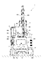
- FIG. 2 is a right side view showing the electric hydraulic excavator according to the embodiment in a state in which a power supply cable is connected to the power supply port of the upper revolving structure;
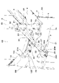
- FIG. 2 is a rear view of the electric hydraulic excavator viewed from the left side of FIG. 1; It is a perspective view which expands and shows a cab, a counterweight, a cable support apparatus, a receiving box, a power supply cable, etc.
- FIG. It is a left side view which expands and shows a cab, a counterweight, a cable support apparatus, a receiving box, a power supply cable, etc.
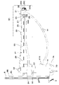
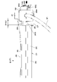
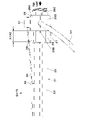
- FIG. It is an enlarged view of the (V) part in FIG. 6 is an enlarged view of the same position as in FIG.
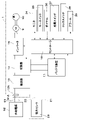
- FIG. 1 is a circuit configuration diagram showing an electric drive system for driving a hydraulic pump of an electric hydraulic excavator;
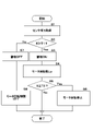
- FIG. 8 is a flowchart showing processing by the controller in FIG. 7;
- the left-right direction of the electric hydraulic excavator 1 is a direction orthogonal to the front-rear direction.
- the left-right direction of the paper corresponds to the front-rear direction (X direction) of the electric hydraulic excavator 1
- the front-back direction of the paper corresponds to the left-right direction (Y direction) of the electric hydraulic excavator 1.
- the vertical direction corresponds to the vertical direction (Z direction) of the electric hydraulic excavator 1 .
- An electric hydraulic excavator 1 (hereinafter referred to as hydraulic excavator 1) as an electric working machine is used, for example, at work sites such as civil engineering, demolition, and underground construction.
- the hydraulic excavator 1 of the embodiment is, for example, a small hydraulic excavator (for example, a machine weight of about 1 to 6 tons) suitable for work in a narrow work site such as underground construction (electric mini excavator, electric small hydraulic excavator ). Further, the hydraulic excavator 1 of the embodiment is configured as a cab-type hydraulic excavator 1 .
- a hydraulic excavator 1 includes a self-propelled crawler-type lower traveling body 2, an upper revolving body 3 rotatably mounted on the lower traveling body 2, and a work device 4 provided on the upper revolving body 3. ing.
- the lower traveling body 2 and the upper revolving body 3 constitute the vehicle body of the hydraulic excavator 1 .
- the vehicle body is drivable and rotatable.
- a swing-type working device 4 is attached to the front side of the upper revolving body 3 so as to be able to swing.
- the hydraulic excavator 1 uses the work device 4 to perform earth and sand excavation work and the like.
- the lower traveling body 2 includes, for example, a crawler belt 2A formed by attaching a plurality of shoes to an endless track link, and left and right traveling for causing the hydraulic excavator 1 to travel (self-propelled) by circulating the crawler belt 2A. and a hydraulic motor (not shown).
- a swing device including a swing bearing and a swing hydraulic motor is provided between the lower traveling structure 2 and the upper swing structure 3 .
- the work device 4 also called a front device, has a swing post 4A provided on the front side of the revolving frame 5 so as to be able to swing in the left-right direction.
- a boom 4B is rotatably attached to the swing post 4A.
- An arm 4C is rotatably attached to the tip of the boom 4B.
- a bucket 4D as a working tool is rotatably attached to the tip of the arm 4C.
- the work device 4 also includes a swing cylinder 4E that swings the swing post 4A, a boom cylinder 4F that rotates the boom 4B, an arm cylinder 4G that rotates the arm 4C, and a work tool cylinder that rotates the bucket 4D. and a bucket cylinder 4H as.
- the upper revolving body 3 revolves on the lower traveling body 2 by being driven by the revolving hydraulic motor of the revolving device.
- the upper revolving body 3 has a revolving frame 5 that serves as a support structure (base frame).
- a cab 6 , a counterweight 7 , an exterior cover 8 , an electric motor 9 , a hydraulic pump 10 , a battery device 11 , a control valve device (not shown) and the like are mounted on the revolving frame 5 .
- the work device 4 is attached to the front side of the revolving frame 5 .
- a counterweight 7 is attached to the rear side of the revolving frame 5 .
- the cab 6 is arranged on the left side of the revolving frame 5.
- the cab 6 is formed in a box shape surrounded by a front surface 6A, a rear surface 6B, a left side 6C, a right side 6D and an upper surface 6E.
- the inside of the cab 6 serves as an operator's cab.
- a travel lever/pedal for operating the hydraulic excavator 1, and a working lever. By operating the traveling lever/pedal and the working lever, the operator can travel by the lower traveling body 2, swing the upper revolving body 3, excavate by the working device 4, and the like.
- the counterweight 7 is located on the rear side of the cab 6 and provided at the rear end of the revolving frame 5 in order to balance the weight with the working device 4 .
- the counterweight 7 is formed as an arc-shaped heavy article extending in the left-right direction and protruding rearward at the center in the left-right direction.
- the rear surface 7A of the counterweight 7 is formed as an arcuate surface that fits within a virtual circle having a constant turning radius when the upper turning body 3 turns.
- the counterweight 7 rises upward from the rear end of the revolving frame 5 and covers the battery device 11 and the like from behind.
- An upper end of the counterweight 7 is formed with an overhanging portion 7B projecting forward.
- the rear side of the cab 6 is supported by the projecting portion 7B.
- a power receiving box 12 is provided on the left end side of the projecting portion 7B.
- a cable support device 21 is provided on the right end side of the projecting portion 7B.
- a power supply cable 91 gripped by the cable support device 21 is connected to the power receiving box 12 .
- the exterior cover 8 is located on the front side of the counterweight 7 and provided on the revolving frame 5 . As shown in FIG. 1 , the exterior cover 8 covers the electric motor 9 , the hydraulic pump 10 , the battery device 11 and the like together with the counterweight 7 .
- the exterior cover 8 includes a right exterior cover 8A that covers the electric motor 9, the hydraulic pump 10, the battery device 11 and the like from the right and upper sides, and a left exterior cover 8B that covers the battery device 11 and the like from the left.
- the power receiving box 12 is provided on the left end side of the protruding portion 7B of the counterweight 7.
- the power receiving box 12 has a power supply port 12A (for example, an inlet serving as a female connector) to which the power supply cable 91 is connected.
- a power supply connector 91A (for example, an inlet plug serving as a male connector) of a power supply cable 91 extending from an external power source 92 (FIG. 7) is connected to the power supply port 12A.
- the upper rotating body 3 has the power supply port 12A to which the power supply cable 91 is connected.
- the power supply cable 91 supplies electric power to the electric motor 9 as a power source.
- the power receiving box 12 is provided with a signal connector 12B located below the power feeding port 12A.
- a signal cable 33 for connecting a tension sensor 29 and a controller 16, which will be described later, is connected to the signal connector 12B.
- a rectifier 13, a switch 14, an inverter 15, and a controller 16 shown in FIG. 7, which will be described later, are provided inside the exterior cover 8, in addition to the electric motor 9, the hydraulic pump 10, and the battery device 11, a rectifier 13, a switch 14, an inverter 15, and a controller 16 shown in FIG. 7, which will be described later, are provided.
- the rectifier 13 converts AC current supplied from the external power supply 92 into DC power.
- Switch 14 switches the power supply state among rectifier 13 , battery device 11 and inverter 15 .
- the inverter 15 converts the DC power supplied from the switch 14 into AC power, and supplies the AC power to the electric motor 9 .
- the feed port 12A, the rectifier 13, the switch 14, the battery device 11, the inverter 15, and the electric motor 9 are electrically connected to each other by in-vehicle cables.
- the electric motor 9 is the power source of the hydraulic excavator 1.
- the electric motor 9 is mechanically connected to the hydraulic pump 10, that is, to be able to transmit power (rotation).
- the hydraulic pump 10 supplies pressure oil to various hydraulic actuators (hydraulic cylinders, hydraulic motors) such as the boom cylinder 4F through control valve devices.
- the control valve device is a control valve group consisting of a plurality of directional control valves.
- the control valve device distributes the pressure oil discharged from the hydraulic pump 10 to a plurality of hydraulic actuators (hydraulic cylinders, hydraulic motors) such as the boom cylinder 4F according to the operation of the travel lever/pedal and the working lever.
- the hydraulic excavator 1 can travel, turn, excavate, and the like.
- the power supply connector 91A of the power supply cable 91 is removed from the power supply port 12A of the power receiving box 12, and the power supply cable 91 is removed from the cable support device 21.
- the electric motor 9 is driven by electric power from the battery device 11 .
- the hydraulic excavator 1 can also be operated with the power supply connector 91A of the power supply cable 91 connected to the power supply port 12A of the power receiving box 12 and the power supply cable 91 attached to the cable support device 21 .
- the electric motor 9 is driven by the electric power from the external power supply 92 and the electric power from the battery device 11 for the shortage.
- a cable support device 21 supports the intermediate portion of the power supply cable 91 connected to the power supply port 12A. That is, the power supply cable 91 supported by the cable support device 21 is connected to the power supply port 12A of the power receiving box 12 .
- a cable support device 21 also called a cable stand, comprises a shaft member 22 and an arm member 23 .
- the shaft member 22 is attached to the upper revolving body 3 (upper surface of the counterweight 7) with its axis extending in the vertical direction.
- the arm member 23 is attached to the shaft member 22 so as to be rotatable around the vertical axis of the shaft member 22 .
- the arm member 23 includes a covered cylindrical portion 24 rotatably fitted to the shaft member 22 and a rod portion 25 extending horizontally from the covered cylindrical portion 24 .
- a cable clamp 26 for gripping the power supply cable 91 is provided on the tip side of the arm member 23 , that is, the tip side of the rod portion 25 .
- the arm member 23 can be fixed to the shaft member 22 at a plurality of positions in the rotation direction by a lock mechanism (not shown).
- the arm member 23 is fixed in the cable gripping position shown in FIGS. 1-6.
- the arm member 23 is fixed at a cab side retracted position arranged along the right side surface 6 ⁇ /b>D of the cab 6 .
- the arm member 23 is fixed at a cab rear retracted position arranged along the rear surface 6B of the cab 6 .
- the arm member 23 is selectively fixed to one of three positions: a cable gripping position, a cab side retracted position, and a cab rear retracted position.
- the arm member 23 When working with the hydraulic excavator 1 with the power supply cable 91 connected to the power supply port 12A, the arm member 23 is fixed at the cable gripping position shown in FIGS. That is, the arm member 23 is fixed at a position where the tip side of the arm member 23 (rod portion 25) protrudes from the upper revolving body 3 (rear surface 7A of the counterweight 7). As a result, it is possible to suppress entanglement of the power supply cable 91 when the hydraulic excavator 1 turns, and to suppress trampling of the power supply cable 91 when the hydraulic excavator 1 travels.
- the cable clamp 26 and the like are shown enlarged in FIGS.
- the cable clamp 26 has a pair of clamp members 26A, 26B that can be opened and closed by a hinge mechanism 26D, and a lock 26C that fixes the clamp members 26A, 26B in a closed state.
- the pair of clamp members 26A and 26B are opened and closed using the hinge mechanism 26D as a fulcrum between a closed position where the power supply cable 91 is clamped from the outer peripheral side and an open position where the power supply cable 91 is released.
- the lock 26C holds the power supply cable 91 in the middle and fixes it to the closed position.
- the power supply cable 91 is gripped by the cable clamp 26 at the tip of the arm member 23 (rod portion 25 ) extending horizontally from the shaft member 22 of the cable support device 21 .
- the power supply connector 91A that is the end of the power supply cable 91 is connected to the power supply port 12A of the power reception box 12 .
- Electric power from the external power source 92 is supplied to the hydraulic excavator 1 via the power supply cable 91 , the power supply connector 91 ⁇ /b>A, and the power supply port 12 ⁇ /b>A of the power receiving box 12 .
- the cable clamp 26 is supported by a bracket 27 provided on the tip side of the arm member 23 (rod portion 25).
- the cable clamp 26 can be displaced in a predetermined direction (for example, left and right directions in FIGS. 4 to 6) with respect to the bracket 27 via a spring member 28 as an elastic member and a guide member (not shown). installed.
- the arm member 23 (rod portion 25) of the cable support device 21 is provided with a tension sensor 29 as a load detection sensor.
- a tension sensor 29 detects tension S applied to the wire 30 .
- the wire 30 is stretched between a clamp side wire support portion 31 fixed to the cable clamp 26 and a vehicle body side wire support portion 32 fixed to the arm member 23 (more specifically, the covered cylindrical portion 24). ing. Thereby, the wire 30 is fixed to both the cable clamp 26 on the power supply cable 91 side and the arm member 23 (covered cylindrical portion 24) on the vehicle body side.
- the tension of the wire 30 changes according to the displacement of the cable clamp 26 with respect to the arm member 23 (rod portion 25). That is, the tension of the wire 30 increases as the cable clamp 26 moves away from the arm member 23 (rod portion 25) (to the right in the horizontal direction in FIGS. 4 to 6). In other words, the tension in the wire 30 increases as the cable clamp 26 is displaced away from the vehicle body.
- the tension sensor 29 detects the tension of the wire 30 which changes (tension, relaxation) according to the displacement of the cable clamp 26 . This allows the tension sensor 29 to detect the load applied to the cable clamp 26 and the load applied to the power supply cable 91 .
- the tension sensor 29 detects the amount of displacement of the cable clamp 26 corresponding to the load applied to the power supply cable 91 as the tension applied to the wire 30 .
- the tension sensor 29 is connected to the controller 16 via a signal cable 33 .
- the tension sensor 29 outputs a signal (tension signal) corresponding to the detected tension to the controller 16 .
- the signal cable 33 extending from the tension sensor 29 toward the controller 16 connects the signal connector 12B of the power receiving box 12 from the vehicle body side wire support portion 32 fixed to the arm member 23 (covered cylindrical portion 24). It is disposed (introduced) in the upper revolving body 3 via the .
- the wire 30 , the tension sensor 29 and the controller 16 constitute a cable load detection device (overload detection device) for detecting the load of the power supply cable 91 .
- a spring member 28 and a guide member are provided between the cable clamp 26 and a bracket 27 fixed to the arm member 23 (rod portion 25).
- the guide member guides the cable clamp 26 with respect to the bracket 27 (rod portion 25). That is, the guide member regulates the displacement of the cable clamp 26 relative to the bracket 27 so that it is linearly displaced in one direction (the direction in which the rod portion 25 extends) (horizontal direction in FIGS. 4 to 6).
- the guide member can be composed of, for example, a convex rail (straight member) provided on the bracket 27 and a concave portion provided on the cable clamp 26 and engaged with the rail of the bracket 27 .
- the spring member 28 expands and contracts according to the displacement of the cable clamp 26.
- the cable clamp 26 is displaced in the horizontal direction in FIGS. 4 to 6 according to the load applied to the power supply cable 91, and the spring member 28 expands and contracts.
- the cable clamp 26 is displaced to the right (the side away from the vehicle body) as shown in FIG.
- the cable clamp 26 is displaced to the left (the side closer to the vehicle body) as shown in FIG.
- the electric drive system of the hydraulic excavator 1 is supplied with electric power through a power supply cable 91 from an external power supply 92 such as a commercial power supply located at a position away from the hydraulic excavator 1 .
- the electric drive system of the hydraulic excavator 1 has a function of supplying power from the external power source 92 to the battery device 11 (charging function) and a function of supplying power from the external power source 92 and/or the battery device 11 to the electric motor 9 (driving function).
- Power supply (charging) to the battery device 11 and power supply to the inverter 15 are performed by connecting relays provided in the internal circuit of the switch 14 based on instructions from the controller 16 .
- the external power supply 92 is, for example, three-phase AC power. Rectifier 13 converts the three-phase AC power into DC power.
- the power of the external power supply 92 can be supplied to the hydraulic excavator 1 via the power supply cable 91 and the power supply port 12A.
- the power of the external power supply 92 can be supplied (charged) to the battery device 11 via the power supply cable 91, the power supply port 12A, the rectifier 13, and the switch .
- Electric power from the external power supply 92 can be supplied to the electric motor 9 via the power supply cable 91 , power supply port 12A, rectifier 13 , switch 14 and inverter 15 . Also, the electric power of the battery device 11 can be supplied to the electric motor 9 via the switch 14 and the inverter 15 .
- the input side of the controller 16 is connected to the tension sensor 29, the monitor device 34, the key switch 35, the rotation speed dial 36, the charge switch 37, the lock switch 38, and the battery device 11.
- the output side of controller 16 is connected to monitor device 34 , alarm 39 , battery device 11 , switch 14 and inverter 15 .
- the controller 16 is a vehicle body controller that controls the operation of the hydraulic excavator 1 .
- the controller 16 operates the switch 14 and the inverter 15 based on signals (input signals) from the key switch 35, the rotation speed dial 36, the lock switch 38, the charge switch 37, the monitor device 34, the tension sensor 29 and the battery device 11. Control. Thereby, the controller 16 controls driving of the electric motor 9 that is the driving source of the hydraulic excavator 1 .
- the controller 16 also controls the monitor device 34 (information display control) and alarms (alarm output control). Further, the controller 16 performs necessary control (notification) according to the detected value (tension) detected by the tension sensor 29 .
- the controller 16 includes a microcomputer.
- the controller 16 has memory such as flash memory, ROM, RAM, EEPROM, and an arithmetic circuit (CPU).
- the memory stores a control program for performing necessary notification according to the detected value (tension) of the tension sensor 29, that is, a processing program for executing the processing flow shown in FIG. 8, which will be described later.
- the battery device 11 is provided with a battery monitoring device.
- the controller 16 is connected with a battery monitor.
- the battery monitoring device monitors the state (battery state) of the battery device 11, such as SOC (state of charge), temperature, abnormality, and the like.
- SOC state of charge
- the battery monitor outputs a signal to controller 16 corresponding to the battery status.
- the monitor device 34 is an in-vehicle monitor (monitor).
- the monitor device 34 is provided inside the cab 6 of the hydraulic excavator 1, for example.
- the monitor device 34 displays information to be communicated to the operator who operates the hydraulic excavator 1 .
- the monitor device 34 displays the operating state of the hydraulic excavator 1, the SOC corresponding to the remaining battery capacity of the battery device 11, malfunction information of various devices, warning information, current time, and the like.
- the monitor device 34 is an information notification device that uses a screen to notify the operator of information.
- the key switch 35 is provided inside the cab 6 of the hydraulic excavator 1, for example.
- the key switch 35 is a start/stop switch for starting (power ON) and stopping (power OFF) the hydraulic excavator 1 .
- a signal (ON signal, OFF signal) of the key switch 35 is output to the controller 16 .
- the operator can start and stop the hydraulic excavator 1 by inserting a key into the key switch 35 and rotating the key.
- the charging switch 37 is provided in the cab 6 of the hydraulic excavator 1 or in the power receiving box 12, for example.
- the charging switch 37 is a switch that selects whether or not to supply power from the external power supply 92 to the battery device 11 when the power supply cable 91 is connected to the power supply port 12A. That is, the charging switch 37 is a switch for selecting whether or not to charge the battery device 11 .
- a signal (charging ON signal, charging OFF signal) from the charging switch 37 is input to the controller 16 . The operator can charge the battery device 11 by turning on the charging switch 37 while the power supply cable 91 is connected to the power supply port 12A.
- the lock switch 38 is a detection switch that detects the position of a gate lock lever (not shown). That is, the lock switch 38 is set at the lock position (up position) where the gate lock lever is prohibited from driving the hydraulic actuator of the hydraulic excavator 1 or at the unlock position (down position) where the hydraulic actuator is permitted to be driven. detect if there is A signal (lock signal, unlock signal) from the lock switch 38 is output to the controller 16 .
- the gate lock lever is operated by the operator to a boarding/alighting restricted position (unlocked position) that closes (closes) the boarding/alighting opening of the cab 6 or to a boarding/alighting permitting position (locking position) that opens (opens) the boarding/alighting gate.
- the hydraulic excavator 1 can drive the hydraulic actuator when the gate lock lever is operated to the unlocked position.
- the alarm 39 outputs a warning sound and a warning voice to the operator based on the judgment of the controller 16.
- the alarm 39 is an information notification device that notifies the operator of information by sound.
- the rotation speed dial 36 is a dial that variably sets the rotation speed of the electric motor 9 .
- the rotation speed dial 36 is operated by an operator.
- the rotation speed dial 36 outputs a motor rotation speed command (signal) to the controller 16 according to the operator's operation.
- the controller 16 controls the inverter 15 according to the command of the rotation speed dial. That is, the inverter 15 controls the frequency of the voltage supplied to the electric motor 9 according to the motor rotation speed command from the controller 16 , thereby controlling the rotation speed of the electric motor 9 .
- a hydraulic pump 10 is connected to the electric motor 9 .
- the hydraulic excavator 1 is driven by supplying hydraulic fluid discharged from a hydraulic pump 10 to various hydraulic actuators via a control valve device.
- the amount of hydraulic fluid discharged from hydraulic pump 10 corresponds to the rotational speed of hydraulic pump 10 . Therefore, the higher the rotation speed of the electric motor 9, the higher the speed of the hydraulic actuator, and the lower the rotation speed, the lower the speed of the hydraulic actuator. Further, by stopping the rotation of the electric motor 9, the hydraulic excavator 1 can be stopped.
- the self-propelled work machine described in the aforementioned Patent Document 1 has a load limiter between the trolley that moves along the rail on the ceiling of the work site and the power supply cable. Therefore, in the case of the technique of Patent Document 1, it is necessary to correct (adjust) the tension detection value of the load limiter or the threshold used for control depending on the operating site at that time.
- the hydraulic excavator 1 of the embodiment includes a cable load detection device (overload detection device) for detecting the load of the power supply cable 91 .
- load detection of the power supply cable 91 is performed by the cable support device 21 serving as a support portion on the vehicle body side. Thereby, in the embodiment, it is possible to reduce the time required for adjusting the overload detection device of the power supply cable 91 according to the operating site.
- the hydraulic excavator 1 receives power from the external power supply 92 via the power supply cable 91 .
- the hydraulic excavator 1 is charged and driven by electric power supplied from the outside of the hydraulic excavator 1 .
- the hydraulic excavator 1 includes a power supply port 12A (cable connection portion) to which a power supply cable 91 is connected, a cable support device 21 for supporting the power supply cable 91 guided to the power supply port 12A, and a load applied to the power supply cable 91.
- a tension sensor 29 as a load detection sensor and a controller 16 as a control device to which the detection value of the tension sensor 29 is input are provided.
- the detected value of tension sensor 29 corresponds to the load of power supply cable 91 .
- the controller 16 limits or controls driving of the hydraulic excavator 1 based on the detected value (load) of the tension sensor 29 .
- the cable support device 21 is supported by the vehicle body so as to be extendable from the installation position on the vehicle body. That is, the cable support device 21 rotates the arm member 23 from the cab side retracted position or the cab rear retracted position to the cable gripping position shown in FIGS. can be extended from A tension sensor 29 detects a load applied to the cable support device 21 . That is, the power supply cable 91 is supported by the cable clamp 26 provided on the tip side of the arm member 23 . The load on the cable clamp 26 directly corresponds to the load on the feeder cable 91 . The tension sensor 29 detects the tension (change amount) of the wire 30 (variable member) corresponding to the load of the cable clamp 26 .
- the displacement X1 of the cable clamp 26 is the first allowable value
- the detection value S of the tension sensor 29 when the displacement X of the cable clamp 26 is the first allowable value X1 is T1.
- the displacement amount X2 of the cable clamp 26 is defined as a second allowable value
- the detected value S of the tension sensor 29 when the displacement X of the cable clamp 26 is the second allowable value X2 is defined as T2.
- the tension T1 corresponding to the first allowable value X1 is a threshold value (first threshold value T1) for determining whether or not to issue an alarm and limit the number of revolutions of the electric motor 9 .
- the tension T2 corresponding to the second allowable value X2 is a threshold (second threshold T2) for issuing an alarm and stopping the rotation of the electric motor 9 .
- the controller 16 issues an alarm from the alarm 39 and the monitor device 34, and limits the rotation speed of the electric motor 9. Furthermore, when the displacement amount X of the cable clamp 26 is X2 or more (X2 ⁇ X), that is, when the detection value S of the tension sensor 29 is the second threshold value T2 or more (T2 ⁇ S), the load applied to the power supply cable 91 is becomes even larger. In this case, the controller 16 stops the rotation of the electric motor 9 while issuing an alarm from the alarm 39 and the monitor device 34 .
- the first threshold value T1 and the second threshold value T2 are determined in advance through experiments, calculations, simulations, etc., so that damage to the power supply cable 91 and the power supply port 12A can be suppressed.
- the first threshold T1 is, for example, 70 to 80% of the maximum allowable tension corresponding to the maximum allowable load of the power supply cable 91 or the power supply port 12A
- the second threshold T2 is, for example, the maximum load of the power supply cable 91 or the power supply port 12A. It can be 90-95% of the maximum allowable tension corresponding to the allowable load.
- load detection of the power supply cable 91 is performed in a specific section on the vehicle. That is, the load of the power supply cable 91 is detected by detecting the change (change in tension) of the wire 30 between the clamp-side wire support portion 31 and the vehicle-body-side wire support portion 32 . Therefore, in the embodiment, it is possible to eliminate the need to correct the threshold value and detection value due to differences in cable length, installation location, etc., depending on the operating site. Note that the control of notification according to the detection value of the tension sensor 29 by the controller 16, that is, the control processing shown in FIG. 8 will be described later in detail.
- the hydraulic excavator 1 has the configuration as described above, and the operation thereof will be described next.
- the power supply cable 91 extending from the external power supply 92 is connected to the power supply port 12A of the hydraulic excavator 1 .
- Electric power from the external power supply 92 is thereby supplied to the electric motor 9 via the rectifier 13 , the switch 14 and the inverter 15 .
- the power from the external power source 92 can be used to charge the battery device 11 .
- the electric motor 9 drives the hydraulic pump 10 with power from an external power source 92 and/or the battery device 11 .
- the hydraulic excavator 1 when the hydraulic excavator 1 is driven by electric power from the external power source 92, the hydraulic excavator 1 is operated with the cable support device 21 supporting the intermediate portion of the power supply cable 91 as shown in FIGS. do. That is, in this state, the operator operates the traveling lever/pedal to cause the hydraulic excavator 1 to travel. In addition, the operator operates the working lever to rotate the upper rotating body 3 and excavate earth and sand with the working device 4 . At this time, a large force may be applied to the power supply cable 91 depending on the relationship between the direction in which the hydraulic excavator 1 operates, the length of the power supply cable 91 , and the position of the external power supply 92 . When the detected value S of the tension sensor 29 exceeds a predetermined threshold value T1 or threshold value T2, the controller 16 of the hydraulic excavator 1 performs notification according to the threshold value T1 or threshold value T2.
- control processing performed by the controller 16 that is, the control processing for notifying according to the detection value S of the tension sensor 29 will be described with reference to FIG. 8 is repeatedly executed at a predetermined control cycle (eg, 10 ms) while the controller 16 is energized, for example.
- a predetermined control cycle eg, 10 ms
- the controller 16 when the controller 16 is activated by turning on the key switch, the control process of FIG. 8 is started.
- the controller 16 reads the detected value S of the tension sensor 29 in S1.
- the detected value S read in S1 is compared with the first threshold value T1. That is, it is determined whether or not the detected value S is equal to or greater than the first threshold value T1 (T1 ⁇ S). If "YES" in S2, that is, if it is determined that the detected value S is greater than or equal to the first threshold value T1 (T1 ⁇ S), the process proceeds to S3.
- the alarm is turned ON.
- the operator is notified by displaying a warning on the display screen of the monitor device 34 and/or by emitting a warning sound or warning voice from the alarm 39.
- the rotation speed of the electric motor 9 is limited to a low speed. That is, the controller 16 reduces the rotational speed command to the inverter 15 to reduce the drive speed of the hydraulic excavator 1 .
- the number of revolutions (rotational speed) of the electric motor 9 is limited to a value such that the load on the power supply cable 91 or the power supply port 12A does not suddenly increase even if the hydraulic excavator 1 continues to be driven.
- the rotation speed is limited to 20 to 50% of the rotation speed set by the rotation speed dial 36 .
- the detection value S read in S1 and the second threshold value T2 are compared. That is, it is determined whether or not the detected value S is equal to or greater than the second threshold value T2 (T2 ⁇ S). If "NO" in S5, that is, if it is determined that the detected value S is smaller than the second threshold value T2 (T2>S), the process proceeds to the end. That is, it proceeds to the start through the end, and repeats the processing from S1 onwards.
- the process proceeds to S7.
- the alarm is turned off. That is, in S7, if a warning is displayed on the display screen of the monitor device 34, the display is stopped, and if the alarm 39 is outputting a warning sound or warning voice, the output is stopped.
- S8 following S7 the limitation of the output of the electric motor 9 is turned off. That is, in S8, if the rotation speed of the electric motor 9 is restricted, the restriction is lifted and the rotation speed set by the rotation speed dial 36 is restored. When the restriction on the electric motor 9 is released in S8, the process proceeds to the start via the end, and repeats the processes after S1.
- the hydraulic excavator 1 of the embodiment includes the cable clamp 26 as a cable support member, the tension sensor 29 as a load detection sensor, and the controller 16 as a control device.
- the cable clamp 26 is provided on the upper revolving body 3 that constitutes the vehicle body. Cable clamp 26 supports power supply cable 91 connected to power supply port 12A.
- the tension sensor 29 detects a state quantity (tension) corresponding to the load applied from the power supply cable 91 to the cable clamp 26 .
- the controller 16 notifies when the detected value of the tension sensor 29 (that is, the state quantity detected by the tension sensor 29) exceeds a predetermined threshold value (threshold value T1, threshold value T2).
- the cable clamp 26 that supports the power supply cable 91 connected to the power supply port 12A of the upper revolving body 3 is provided on the upper revolving body 3 that constitutes the vehicle body. Therefore, the detected value of the tension sensor 29 , that is, the state quantity (tension) corresponding to the load applied from the power supply cable 91 to the cable clamp 26 can be made to almost directly correspond to the load applied to the power supply cable 91 . This correspondence relationship does not change substantially even if the operating site changes.
- the thresholds (threshold T1, threshold T2) used for notification that is, the thresholds (threshold T1, threshold T2) used for processing notification for suppressing damage to the power supply cable 91 and the power supply port 12A can be the same. As a result, it is possible to reduce the time required for adjusting the overload detection device (cable load detection device) of the power supply cable 91 according to the operating site.
- the cable clamp 26 is supported by the upper revolving body 3 via the arm member 23 as a vehicle body side support member attached to the upper revolving body 3 .
- the tension sensor 29 detects the amount of change (amount of change in tension) according to the displacement of the cable clamp 26 with respect to the arm member 23 as a state quantity. That is, the tension sensor 29 detects the amount of change (the amount of change in tension) according to the displacement of the cable clamp 26 with respect to the arm member 23 attached to the upper swing body 3 . Therefore, it is possible to set a threshold value for determining whether or not to issue a notification based on the correspondence relationship between "the amount of change according to the displacement of the cable clamp 26" and "the load applied to the power supply cable 91". .
- the end (tip) of the arm member 23 protrudes from the upper revolving body 3, and the cable clamp 26 is supported by the end (tip) of the arm member 23 so as to be displaceable. That is, the cable clamp 26 is displaceably supported at the end (tip) of the arm member 23 which is a portion (protruding portion) projecting from the upper revolving body 3 . Therefore, for example, the distance between the portion of the power supply cable 91 that is supported (held) by the cable clamp 26 and the power supply port 12A can be increased, and the degree of freedom in routing the power supply cable 91 can be improved.
- the power supply cable 91 since the power supply cable 91 is supported by the portion protruding from the upper revolving body 3, the power supply cable 91 may be stepped on by the lower traveling body 2, and the power supply cable 91 may be caught as the upper revolving body 3 turns. can be further reduced.
- a guide member (not shown) is provided between the cable clamp 26 and the arm member 23 (bracket 27) to regulate the direction in which the cable clamp 26 is displaced with respect to the arm member 23 (bracket 27). ) is provided.
- a spring member 28 is provided between the cable clamp 26 and the arm member 23 (bracket 27) as an elastic member that elastically deforms as the cable clamp 26 is displaced. Therefore, the direction of displacement of the cable clamp 26 can be regulated, and large displacement of the cable clamp 26 can be suppressed even when the load applied to the power supply cable 91 is small.
- a variable member that changes according to the displacement of the cable clamp 26 with respect to the arm member 23 is provided.
- the tension sensor 29 as a load detection sensor detects the amount of change (tension) of the wire 30 as a changing member. Therefore, it is possible to set a threshold value for determining whether or not to notify based on the correspondence relationship between the "variation amount (tension) of the wire 30" and the "load applied to the power supply cable 91".
- the wire 30 as a variable member is fixed to both the vehicle body side (the vehicle body side wire support portion 32) and the cable clamp 26 side (the vehicle body side wire support portion 32).
- the tension sensor 29 detects the load applied to the wire 30 as a state quantity. That is, the tension sensor 29 detects the load (tension) applied to the wire 30 fixed to both the vehicle body side (the vehicle body side wire support portion 32) and the cable clamp 26 side (the vehicle body side wire support portion 32). Therefore, it is possible to set a threshold value for determining whether or not to notify based on the correspondence relationship between the "load (tension) applied to the wire 30" and the "load applied to the power supply cable 91".
- the wire 30 is employed as a variable member that changes according to the displacement of the cable clamp 26 with respect to the arm member 23.
- the wire 30 is stretched between the vehicle body side (the vehicle body side wire support portion 32) and the cable clamp 26 side (the clamp side wire support portion 31).
- the wire 30 changes its tension according to the displacement of the cable clamp 26 .
- a tension sensor 29 detects the tension of the wire 30 . Therefore, it is possible to set a threshold value for determining whether or not to notify based on the correspondence relationship between the "tension of the wire 30" and the "load applied to the power supply cable 91".
- the controller 16 notifies by emitting a warning sound from the alarm 39 and/or by displaying a warning on the screen of the monitor device 34 as a monitor.
- the controller 16 notifies by limiting the operation of the hydraulic excavator 1 (limiting the rotation of the electric motor 9). Therefore, the operator can perform a necessary operation (operation for restricting the movement) based on the notification from the controller 16 .
- the operation of the hydraulic excavator 1 is automatically restricted (the output of the electric motor 9 and, by extension, the hydraulic pump 10 is restricted). By these, damage to the power supply cable 91 can be suppressed.
- the controller 16 may notify by turning on a warning light provided in the cab 6, for example. That is, the controller 16 uses warning sound, warning light, warning display on the monitor, or operation restriction as a notification method.
- the controller 16 determines the magnitude of the load on the power supply cable 91 using the detection value S of the tension sensor 29 corresponding to the amount of displacement of the cable clamp 26 . Therefore, it is not necessary to correct the thresholds T1 and T2 for determining the magnitude of the load on the power supply cable 91 . That is, the time required for adjusting the thresholds T1 and T2 can be reduced according to the operating site, and the control (operation control) for protecting the power supply cable 91 can be easily performed.
- the wire 30 is used as a variable member that changes according to the displacement of the cable clamp 26 with respect to the arm member 23, and the amount of change (load) according to the displacement of the cable clamp 26 with respect to the arm member 23 is detected.
- the case where the tension sensor 29 is used as the load detection sensor has been described as an example.
- the present invention is not limited to this.
- the change member is a spring member provided between the arm member (vehicle body side support member) and the cable clamp (cable support member), and the load detection sensor is the load sensor, that is, the spring member. It may be a load sensor that detects the load applied to.
- a displacement sensor that detects the length of the spring member may be used as the load detection sensor.
- a displacement sensor for detecting the displacement of the cable clamp (cable support member) with respect to the arm member (vehicle body side support member) is provided as a load detection sensor.
- a load sensor which serves as a load detection sensor, is provided between the arm member (vehicle support member) and the cable clamp (cable support member). ) may be detected.
- the state quantity detected by the load detection sensor may be any state quantity corresponding to the load applied to the cable clamp (cable support member) via the power supply cable. good too.
- two threshold values T1 and T2 are set, and when the threshold value T1 is exceeded, a warning notification and a restriction notification of the operation of the hydraulic excavator 1 are performed, and the threshold value T2, which is a value larger than the threshold value T1, is issued.
- a case has been described as an example in which notification by a warning and notification by stopping the operation of the hydraulic excavator 1 are performed when the value exceeds.
- the threshold value T1 is exceeded, a warning is issued, and when the threshold value T2, which is a larger value than the threshold value T1, is exceeded, the operation of the hydraulic excavator 1 is restricted, and the threshold value is exceeded.
- T3 which is a value larger than T2
- T3 a threshold value
- T2 a threshold value larger than T2
- one threshold may be set, and when the threshold is exceeded, the operation of the hydraulic excavator 1 may be stopped to notify.
- the "threshold” and the “notification” when the threshold is exceeded can be set (selected) so as to suppress damage to the power supply cable and the power supply port.
- the hydraulic excavator 1 equipped with the swing-type work device 4 has been described as an example.
- hydraulic excavators equipped with a monoboom type work device hydraulic excavators equipped with an offset type work device, etc. can be applied.
- the working tool of the working device 4 is the bucket 4D
- a working device equipped with other working tools such as a crusher may be used.
- the hydraulic excavator 1 in which the battery device 11 is mounted on the upper revolving body 3 has been described as an example. That is, in the embodiment, the electric hydraulic excavator 1 in which the electric motor 9 is driven by the electric power from the external power source 92 and is also driven by the electric power charged in the battery device 11 is taken as an example. explained. However, without being limited to this, for example, an electric working machine in which a battery device is not mounted and an electric motor is driven only by electric power from an external power supply may be used.
- the cab specification hydraulic excavator 1 having the cab 6 has been described as an example. However, not limited to this, for example, a canopy specification hydraulic excavator may be used.
- the small-sized hydraulic excavator 1 was taken as an example, but it may be applied to medium-sized or larger hydraulic excavators, for example.
- a vehicle body having no revolving body for example, a front vehicle body having front wheels and a rear vehicle body having rear wheels
- can be connected via a connecting shaft to be articulated can be used.
- the hydraulic excavator 1 was taken as an example of the working machine, but it is not limited to this, and can be widely applied to various working machines such as wheel loaders, forklifts, tractors, and combine harvesters.
- Electric hydraulic excavator (electric work machine) 2 Undercarriage (body) 3 Upper revolving body (body) 4 work device 9 electric motor (power source) 12A feed port 16 controller 23 arm member (vehicle body side support member) 26 Cable clamp (cable support member) 28 spring member (elastic member) 29 tension sensor (load detection sensor) 30 wire (variable member) 34 monitor device (monitor) 39 Alarm 91 Power supply cable
Landscapes
- Engineering & Computer Science (AREA)
- Mining & Mineral Resources (AREA)
- Civil Engineering (AREA)
- General Engineering & Computer Science (AREA)
- Structural Engineering (AREA)
- Mechanical Engineering (AREA)
- Operation Control Of Excavators (AREA)
- Component Parts Of Construction Machinery (AREA)
Abstract
Description
2 下部走行体(車体)
3 上部旋回体(車体)
4 作業装置
9 電動モータ(動力源)
12A 給電口
16 コントローラ
23 アーム部材(車体側支持部材)
26 ケーブルクランプ(ケーブル支持部材)
28 ばね部材(弾性部材)
29 張力センサ(負荷検出センサ)
30 ワイヤ(変化部材)
34 モニタ装置(モニタ)
39 アラーム
91 給電ケーブル
Claims (7)
- 走行可能な車体と、前記車体に取付けられた作業装置とを有し、
前記車体は、動力源に電力を供給する給電ケーブルが接続される給電口を備えた電動式作業機械において、
前記車体に設けられ、前記給電口に接続された前記給電ケーブルを支持するケーブル支持部材と、
前記給電ケーブルから前記ケーブル支持部材に加わる負荷に対応する状態量を検出する負荷検出センサと、
前記負荷検出センサの検出値が所定の閾値を超えたときに報知を行うコントローラと、を備えたことを特徴とする電動式作業機械。 - 前記ケーブル支持部材は、前記車体に取付けられた車体側支持部材を介して前記車体に支持されており、
前記負荷検出センサは、前記状態量として前記車体側支持部材に対する前記ケーブル支持部材の変位に応じた変化量を検出することを特徴とする請求項1に記載の電動式作業機械。 - 前記車体側支持部材の端部は、前記車体から張り出しており、
前記ケーブル支持部材は、前記車体側支持部材の前記端部に変位可能に支持されていることを特徴とする請求項2に記載の電動式作業機械。 - 前記ケーブル支持部材と前記車体側支持部材との間には、前記車体側支持部材に対して前記ケーブル支持部材が変位する方向を規制する案内部材と、前記ケーブル支持部材の変位に伴って弾性変形する弾性部材が設けられていることを特徴とする請求項2に記載の電動式作業機械。
- 前記車体側支持部材に対する前記ケーブル支持部材の変位に応じて変化する変化部材を備え、
前記変化部材は、前記車体側と前記ケーブル支持部材側との両方に固定されており、
前記負荷検出センサは、前記状態量として前記変化部材に加わる負荷を検出することを特徴とする請求項2に記載の電動式作業機械。 - 前記車体側支持部材に対する前記ケーブル支持部材の変位に応じて変化する変化部材を備え、
前記変化部材は、前記車体側と前記ケーブル支持部材側との間にかけわたされたワイヤであり、
前記負荷検出センサは、前記状態量として前記ワイヤの張力を検出することを特徴とする請求項2に記載の電動式作業機械。 - 前記コントローラは、前記報知の方法として、警告音、警告灯、モニタ上での警告表示、または、動作の制限を行うことを特徴とする請求項1に記載の電動式作業機械。
Priority Applications (5)
| Application Number | Priority Date | Filing Date | Title |
|---|---|---|---|
| CN202280021170.0A CN116981815B (zh) | 2021-03-22 | 2022-01-07 | 电动式作业机械 |
| JP2023508649A JP7421007B2 (ja) | 2021-03-22 | 2022-01-07 | 電動式作業機械 |
| EP22774545.2A EP4317610A4 (en) | 2021-03-22 | 2022-01-07 | ELECTRIC WORK MACHINE |
| KR1020237031985A KR102989612B1 (ko) | 2021-03-22 | 2022-01-07 | 전동식 작업 기계 |
| US18/282,452 US20240159019A1 (en) | 2021-03-22 | 2022-01-07 | Electric Construction Machine |
Applications Claiming Priority (2)
| Application Number | Priority Date | Filing Date | Title |
|---|---|---|---|
| JP2021-047603 | 2021-03-22 | ||
| JP2021047603 | 2021-03-22 |
Publications (1)
| Publication Number | Publication Date |
|---|---|
| WO2022201740A1 true WO2022201740A1 (ja) | 2022-09-29 |
Family
ID=83396786
Family Applications (1)
| Application Number | Title | Priority Date | Filing Date |
|---|---|---|---|
| PCT/JP2022/000331 Ceased WO2022201740A1 (ja) | 2021-03-22 | 2022-01-07 | 電動式作業機械 |
Country Status (6)
| Country | Link |
|---|---|
| US (1) | US20240159019A1 (ja) |
| EP (1) | EP4317610A4 (ja) |
| JP (1) | JP7421007B2 (ja) |
| KR (1) | KR102989612B1 (ja) |
| CN (1) | CN116981815B (ja) |
| WO (1) | WO2022201740A1 (ja) |
Cited By (2)
| Publication number | Priority date | Publication date | Assignee | Title |
|---|---|---|---|---|
| JP2024089064A (ja) * | 2022-12-21 | 2024-07-03 | 住友建機株式会社 | ショベル |
| JP2024127662A (ja) * | 2023-03-09 | 2024-09-20 | 株式会社日立建機ティエラ | 電動式建設機械 |
Citations (4)
| Publication number | Priority date | Publication date | Assignee | Title |
|---|---|---|---|---|
| JP2008190231A (ja) * | 2007-02-06 | 2008-08-21 | Shin Caterpillar Mitsubishi Ltd | 電動作業機の給電装置 |
| JP2012219461A (ja) | 2011-04-05 | 2012-11-12 | Kobelco Contstruction Machinery Ltd | 自走式作業機械の制御装置 |
| JP2018017011A (ja) * | 2016-07-27 | 2018-02-01 | 日立建機株式会社 | 電気駆動式作業機械の移動用システム |
| JP2018145698A (ja) * | 2017-03-07 | 2018-09-20 | 住友重機械工業株式会社 | 作業機械 |
Family Cites Families (9)
| Publication number | Priority date | Publication date | Assignee | Title |
|---|---|---|---|---|
| JP5135273B2 (ja) | 2009-03-24 | 2013-02-06 | 日立建機株式会社 | 電動式作業機械のケーブルリール装置 |
| CN103534418B (zh) * | 2011-05-16 | 2016-06-08 | 日立建机株式会社 | 工程机械 |
| JP2013234474A (ja) * | 2012-05-08 | 2013-11-21 | Hitachi Constr Mach Co Ltd | 電動式建設機械 |
| KR101471867B1 (ko) | 2014-07-11 | 2014-12-11 | 이병일 | 굴삭기를 이용한 집재장치 |
| JP2017014687A (ja) * | 2015-06-26 | 2017-01-19 | 日立建機株式会社 | 電動作業補助システム |
| CN105926707B (zh) * | 2016-06-28 | 2018-01-30 | 杭州蓝力电动科技有限公司 | 外供电型电动工程机械 |
| CN106364334B (zh) * | 2016-09-30 | 2019-03-26 | 杭州蓝力电动科技有限公司 | 非道路机械的跟踪移动供电系统 |
| CN106480913A (zh) * | 2016-11-16 | 2017-03-08 | 杭州蓝力电动科技有限公司 | 一种电动工程机械的受电装置 |
| JP2020164263A (ja) * | 2019-03-28 | 2020-10-08 | 株式会社タダノ | クレーン |
-
2022
- 2022-01-07 JP JP2023508649A patent/JP7421007B2/ja active Active
- 2022-01-07 CN CN202280021170.0A patent/CN116981815B/zh active Active
- 2022-01-07 US US18/282,452 patent/US20240159019A1/en active Pending
- 2022-01-07 WO PCT/JP2022/000331 patent/WO2022201740A1/ja not_active Ceased
- 2022-01-07 EP EP22774545.2A patent/EP4317610A4/en active Pending
- 2022-01-07 KR KR1020237031985A patent/KR102989612B1/ko active Active
Patent Citations (4)
| Publication number | Priority date | Publication date | Assignee | Title |
|---|---|---|---|---|
| JP2008190231A (ja) * | 2007-02-06 | 2008-08-21 | Shin Caterpillar Mitsubishi Ltd | 電動作業機の給電装置 |
| JP2012219461A (ja) | 2011-04-05 | 2012-11-12 | Kobelco Contstruction Machinery Ltd | 自走式作業機械の制御装置 |
| JP2018017011A (ja) * | 2016-07-27 | 2018-02-01 | 日立建機株式会社 | 電気駆動式作業機械の移動用システム |
| JP2018145698A (ja) * | 2017-03-07 | 2018-09-20 | 住友重機械工業株式会社 | 作業機械 |
Non-Patent Citations (1)
| Title |
|---|
| See also references of EP4317610A4 |
Cited By (3)
| Publication number | Priority date | Publication date | Assignee | Title |
|---|---|---|---|---|
| JP2024089064A (ja) * | 2022-12-21 | 2024-07-03 | 住友建機株式会社 | ショベル |
| JP2024127662A (ja) * | 2023-03-09 | 2024-09-20 | 株式会社日立建機ティエラ | 電動式建設機械 |
| JP7900315B2 (ja) | 2023-03-09 | 2026-08-04 | 株式会社日立建機ティエラ | 電動式建設機械 |
Also Published As
| Publication number | Publication date |
|---|---|
| KR20230147166A (ko) | 2023-10-20 |
| JP7421007B2 (ja) | 2024-01-23 |
| US20240159019A1 (en) | 2024-05-16 |
| CN116981815B (zh) | 2026-07-07 |
| JPWO2022201740A1 (ja) | 2022-09-29 |
| EP4317610A4 (en) | 2025-05-07 |
| KR102989612B1 (ko) | 2026-07-10 |
| EP4317610A1 (en) | 2024-02-07 |
| CN116981815A (zh) | 2023-10-31 |
Similar Documents
| Publication | Publication Date | Title |
|---|---|---|
| JP5004834B2 (ja) | 作業機械 | |
| KR102372681B1 (ko) | 전동식 건설 기계 | |
| JP5814577B2 (ja) | 電動式作業車両及びそのバッテリ保持構造 | |
| KR101652661B1 (ko) | 건설 기계 | |
| KR102412577B1 (ko) | 작업기계 | |
| US9016418B2 (en) | Construction machine | |
| EP4502302A1 (en) | Work machine | |
| CN103635635B (zh) | 液压挖掘机 | |
| KR20150016933A (ko) | 쇼벨의 제어방법 및 제어장치 | |
| JP7421007B2 (ja) | 電動式作業機械 | |
| CN114174598A (zh) | 建筑机械 | |
| JP6214327B2 (ja) | ハイブリッド式建設機械 | |
| JP2020125625A (ja) | 電気駆動式作業機械 | |
| JP7035378B2 (ja) | 遠隔操作装置 | |
| CN119585487A (zh) | 电动式工程机械 | |
| JP2018017011A (ja) | 電気駆動式作業機械の移動用システム | |
| JP2008069516A (ja) | 電動式建設機械 | |
| US20250250767A1 (en) | Immobilization of electrohydraulic power machine | |
| JP7837419B2 (ja) | 電動式建設機械の給電システム | |
| WO2025143061A1 (ja) | 作業機械 | |
| US20250058653A1 (en) | Electrically driven work machine | |
| JP2025142995A (ja) | 作業機械 | |
| CN120231351A (zh) | 挖土机及挖土机用连接器 | |
| KR20120131293A (ko) | 하이브리드 굴삭기 선회 각도 제어 시스템 | |
| JP2024104811A (ja) | 電動式建設機械 |
Legal Events
| Date | Code | Title | Description |
|---|---|---|---|
| 121 | Ep: the epo has been informed by wipo that ep was designated in this application |
Ref document number: 22774545 Country of ref document: EP Kind code of ref document: A1 |
|
| DPE1 | Request for preliminary examination filed after expiration of 19th month from priority date (pct application filed from 20040101) | ||
| WWE | Wipo information: entry into national phase |
Ref document number: 2023508649 Country of ref document: JP |
|
| WWE | Wipo information: entry into national phase |
Ref document number: 202280021170.0 Country of ref document: CN |
|
| WWE | Wipo information: entry into national phase |
Ref document number: 18282452 Country of ref document: US |
|
| ENP | Entry into the national phase |
Ref document number: 20237031985 Country of ref document: KR Kind code of ref document: A |
|
| WWE | Wipo information: entry into national phase |
Ref document number: 1020237031985 Country of ref document: KR |
|
| WWE | Wipo information: entry into national phase |
Ref document number: 2022774545 Country of ref document: EP |
|
| NENP | Non-entry into the national phase |
Ref country code: DE |
|
| ENP | Entry into the national phase |
Ref document number: 2022774545 Country of ref document: EP Effective date: 20231023 |