WO2022201826A1 - 情報処理システム、情報処理方法、及び、情報処理装置 - Google Patents
情報処理システム、情報処理方法、及び、情報処理装置 Download PDFInfo
- Publication number
- WO2022201826A1 WO2022201826A1 PCT/JP2022/002504 JP2022002504W WO2022201826A1 WO 2022201826 A1 WO2022201826 A1 WO 2022201826A1 JP 2022002504 W JP2022002504 W JP 2022002504W WO 2022201826 A1 WO2022201826 A1 WO 2022201826A1
- Authority
- WO
- WIPO (PCT)
- Prior art keywords
- recognition
- metadata
- information processing
- unit
- camera
- Prior art date
- Legal status (The legal status is an assumption and is not a legal conclusion. Google has not performed a legal analysis and makes no representation as to the accuracy of the status listed.)
- Ceased
Links
Images










Classifications
-
- H—ELECTRICITY
- H04—ELECTRIC COMMUNICATION TECHNIQUE
- H04N—PICTORIAL COMMUNICATION, e.g. TELEVISION
- H04N23/00—Cameras or camera modules comprising electronic image sensors; Control thereof
- H04N23/60—Control of cameras or camera modules
-
- G—PHYSICS
- G03—PHOTOGRAPHY; CINEMATOGRAPHY; ANALOGOUS TECHNIQUES USING WAVES OTHER THAN OPTICAL WAVES; ELECTROGRAPHY; HOLOGRAPHY
- G03B—APPARATUS OR ARRANGEMENTS FOR TAKING PHOTOGRAPHS OR FOR PROJECTING OR VIEWING THEM; APPARATUS OR ARRANGEMENTS EMPLOYING ANALOGOUS TECHNIQUES USING WAVES OTHER THAN OPTICAL WAVES; ACCESSORIES THEREFOR
- G03B13/00—Viewfinders; Focusing aids for cameras; Means for focusing for cameras; Autofocus systems for cameras
- G03B13/32—Means for focusing
- G03B13/34—Power focusing
- G03B13/36—Autofocus systems
-
- G—PHYSICS
- G03—PHOTOGRAPHY; CINEMATOGRAPHY; ANALOGOUS TECHNIQUES USING WAVES OTHER THAN OPTICAL WAVES; ELECTROGRAPHY; HOLOGRAPHY
- G03B—APPARATUS OR ARRANGEMENTS FOR TAKING PHOTOGRAPHS OR FOR PROJECTING OR VIEWING THEM; APPARATUS OR ARRANGEMENTS EMPLOYING ANALOGOUS TECHNIQUES USING WAVES OTHER THAN OPTICAL WAVES; ACCESSORIES THEREFOR
- G03B17/00—Details of cameras or camera bodies; Accessories therefor
- G03B17/18—Signals indicating condition of a camera member or suitability of light
-
- G—PHYSICS
- G06—COMPUTING OR CALCULATING; COUNTING
- G06T—IMAGE DATA PROCESSING OR GENERATION, IN GENERAL
- G06T7/00—Image analysis
- G06T7/70—Determining position or orientation of objects or cameras
-
- G—PHYSICS
- G06—COMPUTING OR CALCULATING; COUNTING
- G06V—IMAGE OR VIDEO RECOGNITION OR UNDERSTANDING
- G06V40/00—Recognition of biometric, human-related or animal-related patterns in image or video data
- G06V40/20—Movements or behaviour, e.g. gesture recognition
- G06V40/23—Recognition of whole body movements, e.g. for sport training
-
- H—ELECTRICITY
- H04—ELECTRIC COMMUNICATION TECHNIQUE
- H04N—PICTORIAL COMMUNICATION, e.g. TELEVISION
- H04N23/00—Cameras or camera modules comprising electronic image sensors; Control thereof
- H04N23/60—Control of cameras or camera modules
- H04N23/61—Control of cameras or camera modules based on recognised objects
- H04N23/611—Control of cameras or camera modules based on recognised objects where the recognised objects include parts of the human body
-
- H—ELECTRICITY
- H04—ELECTRIC COMMUNICATION TECHNIQUE
- H04N—PICTORIAL COMMUNICATION, e.g. TELEVISION
- H04N23/00—Cameras or camera modules comprising electronic image sensors; Control thereof
- H04N23/60—Control of cameras or camera modules
- H04N23/63—Control of cameras or camera modules by using electronic viewfinders
- H04N23/633—Control of cameras or camera modules by using electronic viewfinders for displaying additional information relating to control or operation of the camera
- H04N23/635—Region indicators; Field of view indicators
-
- H—ELECTRICITY
- H04—ELECTRIC COMMUNICATION TECHNIQUE
- H04N—PICTORIAL COMMUNICATION, e.g. TELEVISION
- H04N23/00—Cameras or camera modules comprising electronic image sensors; Control thereof
- H04N23/60—Control of cameras or camera modules
- H04N23/64—Computer-aided capture of images, e.g. transfer from script file into camera, check of taken image quality, advice or proposal for image composition or decision on when to take image
-
- G—PHYSICS
- G06—COMPUTING OR CALCULATING; COUNTING
- G06T—IMAGE DATA PROCESSING OR GENERATION, IN GENERAL
- G06T2207/00—Indexing scheme for image analysis or image enhancement
- G06T2207/10—Image acquisition modality
- G06T2207/10016—Video; Image sequence
-
- G—PHYSICS
- G06—COMPUTING OR CALCULATING; COUNTING
- G06T—IMAGE DATA PROCESSING OR GENERATION, IN GENERAL
- G06T2207/00—Indexing scheme for image analysis or image enhancement
- G06T2207/30—Subject of image; Context of image processing
- G06T2207/30196—Human being; Person
- G06T2207/30201—Face
-
- G—PHYSICS
- G06—COMPUTING OR CALCULATING; COUNTING
- G06V—IMAGE OR VIDEO RECOGNITION OR UNDERSTANDING
- G06V20/00—Scenes; Scene-specific elements
- G06V20/70—Labelling scene content, e.g. deriving syntactic or semantic representations
-
- H—ELECTRICITY
- H04—ELECTRIC COMMUNICATION TECHNIQUE
- H04N—PICTORIAL COMMUNICATION, e.g. TELEVISION
- H04N5/00—Details of television systems
- H04N5/76—Television signal recording
- H04N5/765—Interface circuits between an apparatus for recording and another apparatus
- H04N5/77—Interface circuits between an apparatus for recording and another apparatus between a recording apparatus and a television camera
Definitions
- the present technology relates to an information processing system, an information processing method, and an information processing apparatus.
- the present invention relates to an information processing method and an information processing apparatus.
- the present technology has been made in view of such circumstances, and enables effective use of the result of recognition processing on a captured image by an information processing device that controls an imaging device.
- An information processing system includes an imaging device that captures a captured image and an information processing device that controls the imaging device, and the information processing device recognizes the captured image.
- a recognition unit that performs processing
- a recognition metadata generation unit that generates recognition metadata including data based on the result of the recognition processing
- an output unit that outputs the recognition metadata to the imaging device.
- recognition processing is performed on the captured image, recognition metadata including data based on the result of the recognition processing is generated, and the recognition metadata is output to the imaging device.
- an information processing device that controls an imaging device that captures a captured image performs recognition processing on the captured image, and generates data based on the result of the recognition processing. and outputting the recognition metadata to the imaging device.
- recognition processing is performed on a captured image, recognition metadata including data based on the result of the recognition processing is generated, and the recognition metadata is output to the imaging device.
- An information processing system includes an imaging device that captures a captured image and an information processing device that controls the imaging device, and the information processing device recognizes the captured image.
- a recognition unit that performs processing
- a recognition metadata generation unit that generates recognition metadata including data based on the result of the recognition processing
- an output unit that outputs the recognition metadata to a subsequent device.
- recognition processing is performed on a captured image, recognition metadata including data based on the result of the recognition processing is generated, and the recognition metadata is output to a subsequent device.
- an information processing device that controls an imaging device that captures a captured image performs recognition processing on the captured image, and generates data based on the result of the recognition processing. generating recognition metadata including the recognition metadata, and outputting the recognition metadata to a subsequent device;
- recognition processing is performed on a captured image, recognition metadata including data based on the result of the recognition processing is generated, and the recognition metadata is output to a subsequent device.
- An information processing apparatus includes a recognition unit that performs recognition processing on a captured image captured by an imaging device; A data generator and an output unit for outputting the recognition metadata.
- recognition processing is performed on a captured image captured by an imaging device, recognition metadata including data based on the result of the recognition processing is generated, and the recognition metadata is output. be done.
- FIG. 1 is a block diagram showing an embodiment of an information processing system to which the present technology is applied;
- FIG. 3 is a block diagram showing an example functional configuration of a CPU of the camera;
- FIG. 3 is a block diagram showing an example functional configuration of a CPU of the CCU;
- FIG. 3 is a block diagram showing an example functional configuration of an information processing unit of the CCU;
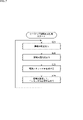
- 4 is a flowchart for explaining focus index display processing;
- FIG. 10 is a diagram showing an example of a focus index display; 9 is a flowchart for explaining peaking highlighting processing;
- FIG. 4 is a diagram showing an example of a video frame;
- FIG. 4 is a diagram showing an example of area recognition;
- FIG. 10 is a diagram for explaining mask processing;
- FIG. 4 is a diagram showing a display example of a luminance waveform of a video frame before mask processing and a vector scope;
- FIG. 10 is a diagram showing a display example of a luminance waveform and a vector scope of a video frame after mask processing of the first method;
- FIG. 10 is a diagram showing a display example of a luminance waveform of a video frame and a vector scope after mask processing of the second method;
- FIG. 11 is a diagram showing a display example of a luminance waveform of a video frame and a vector scope after mask processing of the third method; 5 is a flowchart for explaining reference direction correction processing; It is a figure which shows the example of a feature point map.
- FIG. 4 is a diagram for explaining a method of detecting an imaging direction based on feature points;
- FIG. 4 is a diagram for explaining a method of detecting an imaging direction based on feature points; 4 is a flowchart for explaining subject recognition/embedding processing;
- FIG. 10 is a diagram showing an example of an image superimposed with information indicating the result of object recognition; It is a figure which shows the structural example of a computer.
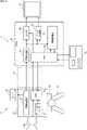
- FIG. 1 is a block diagram showing an embodiment of an information processing system 1 to which the present technology is applied.
- the information processing system 1 includes a camera 11, a tripod 12, a platform 13, a camera cable 14, a CCU (Camera Control Unit) 15 that controls the camera 11, an operation panel 16, and a monitor 17.
- a camera 11 is installed on a camera platform 13 attached to a tripod 12 so as to be rotatable in pan, tilt and roll directions.
- Camera 11 and CCU 15 are connected by camera cable 14 .
- the camera 11 includes a main body 21, a lens 22, and a viewfinder 23.
- a lens 22 and a viewfinder 23 are attached to the body portion 21 .
- the body portion 21 includes a signal processing portion 31 , a motion sensor 32 and a CPU 33 .
- the lens 22 supplies lens information regarding the lens 22 to the CPU 33 .
- the lens information includes, for example, the focal length of the lens 22, the focal length, and lens control values such as the iris value, specifications, and the like.
- the signal processing unit 31 and the signal processing unit 51 of the CCU 15 share video signal processing.
- the signal processing unit 31 performs predetermined signal processing on a video signal obtained by an image sensor (not shown) capturing an image of a subject through the lens 22, and an image captured by the image sensor is obtained. Generate a video frame.
- the signal processing unit 31 supplies the video frames to the viewfinder 23 and outputs them to the signal processing unit 51 of the CCU 15 via the camera cable 14 .
- the motion sensor 32 includes, for example, an angular velocity sensor and an acceleration sensor, and detects the angular velocity and acceleration of the camera 11.
- the motion sensor 32 supplies the CPU 33 with data indicating the detection results of the angular velocity and acceleration of the camera 11 .
- the CPU 33 controls the processing of each part of the camera 11. For example, the CPU 33 changes the control values of the camera 11 or causes the viewfinder 23 to display information about the control values based on the control signal input from the CCU 15 .
- the CPU 33 detects the orientation (pan angle, tilt angle, roll angle) of the camera 11, that is, the imaging direction of the camera 11, based on the detection result of the angular velocity of the camera 11. For example, the CPU 33 detects the imaging direction (orientation) of the camera 11 by setting a reference direction in advance and cumulatively calculating (integrating) the amount of change in the orientation of the camera 11 with reference to the reference direction. Note that the CPU 33 may use the detection result of the acceleration of the camera 11 to detect the imaging direction of the camera 11 .
- the reference direction of the camera 11 is the direction in which the pan angle, tilt angle, and roll angle of the camera 11 are 0 degrees.
- the CPU 33 corrects the internally held reference direction based on the correction data included in the recognition metadata input from the CCU 15 .
- the CPU 33 acquires control information for the main unit 21 such as shutter speed and color balance.
- the CPU 33 generates camera metadata including imaging direction information, control information, and lens information of the camera 11 .
- the CPU 33 outputs camera metadata to the CPU 52 of the CCU 15 via the camera cable 14 .
- the CPU 33 controls the display of the through image (live view) displayed on the viewfinder 23 . Further, the CPU 33 controls display of information superimposed on the through image based on recognition metadata and control signals input from the CCU 15 .
- the viewfinder 23 displays a through image based on the video frame supplied from the signal processing unit 31, and displays various information superimposed on the through image.
- the CCU 15 includes a signal processing section 51 , a CPU 52 , an information processing section 53 , an output section 54 and a mask processing section 55 .
- the signal processing unit 51 performs predetermined video signal processing on the video frames generated by the signal processing unit 31 of the camera 11 .
- the signal processing section 51 supplies the video frame after the video signal processing to the information processing section 53 , the output section 54 and the mask processing section 55 .
- the CPU 52 controls the processing of each part of the CCU 15.
- the CPU 52 also communicates with the operation panel 16 and acquires control signals input from the operation panel 16 .
- the CPU 52 outputs the acquired control signal to the camera 11 via the camera cable 14 or supplies it to the mask processing section 55 as necessary.
- the CPU 52 supplies camera metadata input from the camera 11 to the information processing section 53 and the mask processing section 55 .
- the CPU 52 outputs recognition metadata supplied from the information processing section 53 to the camera 11 via the camera cable 14 , outputs it to the operation panel 16 , and supplies it to the mask processing section 55 .
- the CPU 52 generates incidental metadata based on the camera metadata and recognition metadata, and supplies it to the output unit 54 .
- the information processing section 53 performs various recognition processes using computer vision, AI (Artificial Intelligence), machine learning, etc. on video frames.
- the information processing section 53 performs subject recognition, area recognition, and the like within the video frame. More specifically, for example, the information processing unit 53 performs extraction of feature points, matching, detection of the imaging direction of the camera 11 based on tracking (orientation detection), skeleton detection by machine learning, face detection, face identification, Eye detection, object detection, action recognition, semantic segmentation, etc. Further, the information processing section 53 detects the shift in the imaging direction detected by the camera 11 based on the video frame.
- the information processing section 53 generates recognition metadata including data based on the result of recognition processing.
- the information processing section 53 supplies recognition metadata to the CPU 52 .
- the output unit 54 arranges (adds) video frames and incidental metadata to an output signal in a predetermined format (for example, an SDI (Serial Digital Interface) signal), and outputs it to the subsequent monitor 17 .
- a predetermined format for example, an SDI (Serial Digital Interface) signal
- the mask processing unit 55 performs mask processing on video frames based on the control signal and recognition metadata supplied from the CPU 52 .
- the masking process is a process of masking an area (hereinafter referred to as a mask area) other than an area of a subject of a predetermined type in a video frame.
- the output unit 54 arranges (adds) the masked video frame to an output signal (for example, an SDI signal) in a predetermined format, and outputs it to the monitor 17 in the subsequent stage.
- the operation panel 16 is composed of, for example, an MSU (Master Setup Unit), an RCP (Remote Control Panel), and the like.
- the operation panel 16 is used by a user such as a VE (Video Engineer), generates control signals based on user operations, and outputs the control signals to the CPU 52 .
- VE Video Engineer
- the monitor 17 is used, for example, by a user such as a VE to check the video captured by the camera 11 .
- the monitor 17 displays images based on the output signal from the output section 54 .
- the monitor 17 displays the masked image based on the output signal from the mask processing section 55 .
- the monitor 17 displays the luminance waveform, vector scope, etc. of the masked video frame.
- description of the camera cable 14 will be omitted as appropriate in the process of transmitting signals and data between the camera 11 and the CCU 15.
- the description of the camera cable 14 may be omitted and simply stated that the camera 11 outputs video frames to the CCU 15 .
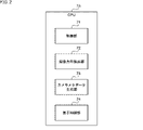
- FIG. 2 shows a configuration example of functions realized by the CPU 33 of the camera 11. As shown in FIG., when the CPU 33 executes a predetermined control program, functions including the control unit 71, the imaging direction detection unit 72, the camera metadata generation unit 73, and the display control unit 74 are realized.
- the control unit 71 controls processing of each unit of the camera 11 .
- the imaging direction detection unit 72 detects the imaging direction of the camera 11 based on the detection result of the angular velocity of the camera 11 . Note that the imaging direction detection unit 72 may use the acceleration detection result of the camera 11 to detect the imaging direction of the camera 11 . Also, the imaging direction detection unit 72 corrects the reference direction of the camera 11 based on the recognition metadata input from the CCU 15 .
- the camera metadata generation unit 73 generates camera metadata including imaging direction information, control information, and lens information of the camera 11 .
- the camera metadata generator 73 outputs camera metadata to the CPU 52 of the CCU 15 .
- the display control unit 74 controls display of the through image by the viewfinder 23 . Further, the display control unit 74 controls display of information superimposed on the through image by the viewfinder 23 based on the recognition metadata input from the CCU 15 .
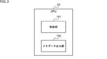
- FIG. 3 shows a configuration example of functions realized by the CPU 52 of the CCU 15. As shown in FIG., the functions including the control unit 101 and the metadata output unit 102 are realized by the CPU 52 executing a predetermined control program.
- the control unit 101 controls the processing of each unit of the CCU 15.
- the metadata output unit 102 supplies camera metadata input from the camera 11 to the information processing unit 53 and the mask processing unit 55 .
- the metadata output unit 102 outputs recognition metadata supplied from the information processing unit 53 to the camera 11 , the operation panel 16 , and the mask processing unit 55 .
- the metadata output unit 102 generates incidental metadata based on the camera metadata and the recognition metadata supplied from the information processing unit 53 and supplies it to the output unit 54 .
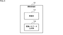
- FIG. 4 shows a configuration example of the information processing unit 53 of the CCU 15. As shown in FIG.
- the information processing section 53 includes a recognition section 131 and a recognition metadata generation section 132 .
- the recognition unit 131 performs various recognition processes on video frames.
- the recognition metadata generation unit 132 generates recognition metadata including data based on recognition processing by the recognition unit 131 .
- the recognition metadata generator 132 supplies recognition metadata to the CPU 52 .
- This process is started, for example, when the user uses the operation panel 16 to input an instruction to start displaying the focus index values, and ends when an instruction to stop displaying the focus index values is input.
- step S1 the information processing system 1 performs imaging processing.
- an image sensor (not shown) captures an image of a subject and supplies the obtained video signal to the signal processing unit 31 .
- the signal processing unit 31 performs predetermined video signal processing on the video signal supplied from the image sensor to generate a video frame.
- the signal processing unit 31 supplies the video frames to the viewfinder 23 and outputs them to the signal processing unit 51 of the CCU 15 .
- the viewfinder 23 displays a through image based on the video frame under the control of the display control section 74 .
- the lens 22 supplies lens information regarding the lens 22 to the CPU 33 .
- the motion sensor 32 detects the angular velocity and acceleration of the camera 11 and supplies data indicating the detection result to the CPU 33 .
- the imaging direction detection unit 72 detects the imaging direction of the camera 11 based on the detection results of the angular velocity and acceleration of the camera 11 . For example, the imaging direction detection unit 72 cumulatively calculates (integrates) the amount of change in the direction (angle) of the camera 11 based on the angular velocity detected by the motion sensor 32 with reference to a preset reference direction. , the imaging direction (orientation) of the camera 11 is detected.
- the camera metadata generation unit 73 generates camera metadata including imaging direction information, lens information, and control information of the camera 11 .
- the camera metadata generation unit 73 outputs camera metadata corresponding to the video frame to the CPU 52 of the CCU 15 in synchronization with the output of the video frame by the signal processing unit 31 .
- the video frame is associated with camera metadata including imaging direction information, control information, and lens information of the camera 11 near the imaging time of the video frame.
- a signal processing unit 51 of the CCU 15 performs predetermined video signal processing on video frames acquired from the camera 11, and outputs the video frames subjected to the video signal processing to an information processing unit 53, an output unit 54, and a mask processing unit. 55.
- the metadata output unit 102 of the CCU 15 supplies camera metadata acquired from the camera 11 to the information processing unit 53 and mask processing unit 55 .
- the recognition unit 131 of the CCU 15 performs subject recognition.
- the recognition unit 131 uses skeleton detection, face detection, pupil detection, object detection, and the like to recognize the type of subject for which the focus index value in the video frame is to be displayed. Note that when there are a plurality of subjects of the type for which the focus index value is to be displayed in the video frame, the recognition unit 131 recognizes each subject individually.
- step S3 the recognition unit 131 of the CCU 15 calculates a focus index value. Specifically, the recognition unit 131 calculates a focus index value in an area including each recognized subject.
- the method of calculating the focus index value is not particularly limited.
- frequency analysis using Fourier transform, cepstrum analysis, DfD (Depth from Defocus) technology, etc. are used as a method of calculating the focus index value.
- step S4 the CCU 15 generates recognition metadata.
- the recognition metadata generation unit 132 generates recognition metadata including the position and focus index value of each subject recognized by the recognition unit 131 and supplies the recognition metadata to the CPU 52 .
- a metadata output unit 102 outputs recognition metadata to the CPU 33 of the camera 11 .
- step S ⁇ b>5 the viewfinder 23 of the camera 11 displays the focus index under the control of the display control section 74 .
- FIG. 6 schematically shows an example of the focus index display.
- FIG. 6A shows an example of a through image displayed on the viewfinder 23 before displaying the focus index.
- B of FIG. 6 shows an example of a through image displayed on the viewfinder 23 after the focus index is displayed.
- people 201a to 201c are shown in the through image.
- Person 201 a is closest to camera 11 and person 201 c is farthest from camera 11 .
- the camera 11 is focused on the person 201a.
- the right eyes of the persons 201a to 201c are set as the display target of the focus index value. Then, as shown in FIG. 6B, an indicator 202a, which is a circular image indicating the position of the right eye of the person 201a, is displayed around the right eye of the person 201a. An indicator 202b, which is a circular image indicating the position of person 201b's right eye, is displayed around person 201b's right eye. An indicator 202c, which is a circular image indicating the position of person 201c's right eye, is displayed around person 201c's right eye.
- bars 203a to 203c indicating the focus index values for the right eyes of the persons 201a to 201c are displayed below the through images.
- a bar 203a indicates the focus index value for the right eye of the person 201a.
- a bar 203b indicates the focus index value for the right eye of the person 201b.
- a bar 203c indicates the focus index value for the right eye of the person 201c.
- the length of the bars 203a to 203c indicates the value of the focus index value.
- the bars 203a to 203c are set in different display modes (for example, different colors).
- the indicator 202a and the bar 203a are set to have the same display mode (for example, the same color).
- the indicator 202b and the bar 203b are set to have the same display mode (for example, the same color).
- the indicator 202c and the bar 203c are set to have the same display mode (for example, the same color). This allows a user (for example, a photographer) to easily grasp the correspondence between each subject and the focus index value.
- the focus index value cannot be used if the subject to be focused moves out of the area. Gone.
- a desired type of subject is automatically tracked, and the focus index value of the subject is displayed. Also, when there are a plurality of subjects whose focus index values are to be displayed, the focus index values are displayed individually. Further, the subject and the focus index value are associated with each subject in a different display mode.
- step S1 After that, the process returns to step S1, and the processes after step S1 are executed.
- This process is started, for example, when the user uses the operation panel 16 to input an instruction to start the peaking highlighting display, and ends when the user inputs an instruction to stop the peaking highlighting display.
- peaking highlighting is a function for highlighting high-frequency components in a video frame, and is also called detail highlighting. Peaking highlighting is used, for example, to assist manual focus operations.
- step S21 imaging processing is performed in the same manner as the processing in step S1 of FIG.
- step S22 the recognition unit 131 of the CCU 15 performs subject recognition.
- the recognition unit 131 recognizes the region and type of each subject in the video frame using object detection, semantic segmentation, or the like.
- step S23 the CCU 15 generates recognition metadata.
- the recognition metadata generation unit 132 generates recognition metadata including the position and type of each subject recognized by the recognition unit 131 and supplies the recognition metadata to the CPU 52 .
- a metadata output unit 102 outputs recognition metadata to the CPU 33 of the camera 11 .
- step S24 the viewfinder 23 of the camera 11, under the control of the display control unit 74, limits the area based on the recognition metadata and performs peaking highlighting display.
- FIG. 8 schematically shows an example of peaking highlighting for a golf tee shot scene.
- FIG. 8A shows an example of a through image displayed on the viewfinder 23 before peaking highlight display.
- FIG. 8B shows an example of a through image displayed on the viewfinder 23 after peaking highlighting, and the highlighted area is hatched.
- the high-frequency components of the background are also highlighted, which may reduce visibility.
- the subject to be displayed with peaking emphasis can be limited to a shaded area containing a person.
- high-frequency components such as edges in shaded areas are highlighted using auxiliary lines or the like.
- step S21 After that, the process returns to step S21, and the processes after step S21 are executed.
- This process is started, for example, when the user uses the operation panel 16 to input an instruction to start the image masking process, and ends when the user inputs an instruction to stop the image masking process.
- step S41 imaging processing is performed in the same manner as the processing in step S1 of FIG.
- step S42 the recognition unit 131 of the CCU 15 performs area recognition.
- the recognizing unit 131 divides the video frame into a plurality of regions for each subject type by performing semantic segmentation on the video frame.
- step S43 the CCU 15 generates recognition metadata.
- the recognition metadata generation unit 132 generates recognition metadata including the area within the video frame recognized by the recognition unit 131 and its type, and supplies the recognition metadata to the CPU 52 .
- the metadata output unit 102 supplies recognition metadata to the mask processing unit 55 .
- step S44 the mask processing unit 55 performs mask processing.
- the user uses the operation panel 16 to select the type of subject to be left as it is without masking.
- the control unit 101 supplies data indicating the type of subject selected by the user to the mask processing unit 55 .
- the mask processing unit 55 performs mask processing on subject regions (mask regions) other than the type selected by the user in the video frame.
- the area of the subject of the type selected by the user will be referred to as a recognition target area.
- FIG. 10 a specific example of mask processing will be described with reference to FIGS. 10 to 12.
- FIG. 10 a specific example of mask processing will be described with reference to FIGS. 10 to 12.
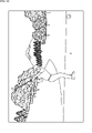
- FIG. 10 schematically shows an example of a video frame that captures a golf tee shot.
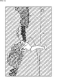
- FIG. 11 shows an example of the results of area recognition performed on the video frame of FIG.
- the video frame is divided into regions 251 through 255, each region shown with a different pattern.
- a region 251 is a region in which a person appears (hereinafter referred to as a person region).
- a region 252 is a region where the ground is shown.
- a region 253 is a region in which trees are shown.
- a region 254 is a region in which the sky is shown.
- a region 255 is the region where the tee marker is shown.
- FIG. 12 schematically shows an example in which recognition target areas and mask areas are set for the video frame of FIG.
- hatched areas areas corresponding to areas 252 to 255 in FIG. 11
- an area not drawn with oblique lines an area corresponding to the area 251 in FIG. 11 is set as the recognition target area.
- pixel signals in the mask area are replaced with black signals. That is, the mask area is blacked out.
- pixel signals in the recognition target area are not particularly changed.
- the chroma component of the pixel signal in the mask area is reduced.
- the U and V components of the chroma components of the pixel signal in the mask area are set to zero.
- the luminance component of the pixel signal in the mask area is not changed.
- the pixel signals of the recognition target area are not particularly changed.
- chroma components of pixel signals in the masked area are reduced in the same manner as in the masking process of the second method.
- the U and V components of the chroma components of the pixel signal in the mask area are set to zero.
- the luminance component of the mask area is reduced.
- the luminance component of the mask area is converted by the following equation (1), and the contrast of the luminance component of the mask area is compressed.
- pixel signals in the recognition target area are not particularly changed.
- Yin indicates the luminance component before mask processing. Yout indicates the luminance component after mask processing.
- gain indicates a predetermined gain and is set to a value less than 1.0.
- offset indicates an offset value.
- the mask processing unit 55 arranges (adds) the masked video frame to an output signal in a predetermined format, and outputs the output signal to the monitor 17 .
- step S45 the monitor 17 displays the masked video and waveform. Specifically, the monitor 17 displays an image based on the masked image frame based on the output signal acquired from the mask processing unit 55 . The monitor 17 also displays the luminance waveform of the video frame masked for adjusting the brightness. Further, the monitor 17 displays a vectorscope of the video frame masked for color tone adjustment.
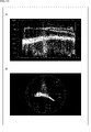
- 13 to 16 show display examples of the luminance waveform and vector scope of the video frame in FIG.
- FIG. 13A shows a display example of the luminance waveform of the video frame before masking
- FIG. 13B shows a vectorscope display example of the video frame before masking.
- the horizontal axis of the luminance waveform indicates the horizontal position of the video frame, and the vertical axis indicates the amplitude of the luminance.
- the circumferential direction of the vectorscope indicates hue, and the radial direction indicates saturation. This also applies to FIGS. 14 to 16.
- FIG. 14 to 16 illustrates the horizontal axis of the luminance waveform.
- the luminance waveform before mask processing the luminance waveform of the entire video frame is displayed.
- the vectorscope before mask processing waveforms of hue and saturation of the entire video frame are displayed.
- luminance and chroma components in areas other than the recognition target area become noise.
- the brightness waveform and vectorscope waveform for the area of the subject greatly differ depending on whether the same subject is frontlit or backlit. Therefore, it is particularly difficult for an inexperienced user to adjust the brightness and color tone of the recognition target area while looking at the luminance waveform and vector scope before mask processing.
- FIG. 14A shows a display example of the luminance waveform of the video frame after the mask processing of the first method
- FIG. 14B shows a display example of the vector scope of the video frame after the mask processing of the first method. showing.
- the luminance waveform after the mask processing of the first method the luminance waveform of only the person region, which is the recognition target region, is displayed. Therefore, for example, it becomes easy to adjust the brightness only for a person.
- the hue and saturation waveforms of only the person area, which is the recognition target area are displayed. Therefore, for example, it becomes easy to adjust the color tone only for a person.
- the visibility of the video frame is reduced because the masked area is blacked out. In other words, the user cannot confirm the image other than the recognition target area.
- FIG. 15A shows a display example of the luminance waveform of the video frame after the mask processing of the second method
- FIG. 15B shows a display example of the vector scope of the video frame after the mask processing of the second method. showing.
- the luminance waveform after masking in the second method is similar to the luminance waveform before masking in A of FIG. Therefore, for example, it becomes difficult to adjust the brightness only for a person.
- the waveform of the vector scope after the mask processing of the second method is similar to the waveform of the vector scope after the mask processing of the first method in B of FIG. Therefore, for example, it becomes easy to adjust the color tone only for a person.
- the video frame after the mask processing of the second method retains the luminance component of the masked area as it is, so the visibility is improved compared to the video frame after the mask processing of the first method.
- FIG. 16A shows a display example of the luminance waveform of the video frame after the mask processing of the third method
- FIG. 16B shows a display example of the vector scope of the video frame after the mask processing of the third method. showing.
- the waveform of the person area which is the recognition target area, appears to stand out due to the compression of the contrast of the mask area. Therefore, for example, it becomes easy to adjust the brightness only for a person.
- the waveform of the vector scope after the mask processing of the third method is similar to the waveform of the vector scope after the mask processing of the first method in B of FIG. Therefore, for example, it becomes easy to adjust the color tone only for a person.
- the brightness component of the masked area remains even though the contrast is compressed. improve sexuality.
- the masking process of the third method it is possible to easily adjust the brightness and color tone of the recognition target area while ensuring the visibility of the masked area of the video frame.
- the luminance of video frames may be displayed by other methods such as parade display and histogram.
- the brightness of the recognition target area can be easily adjusted by using the mask processing of the first or third method.
- step S41 After that, the process returns to step S41, and the processes after step S41 are executed.
- the monitor 17 does not require special processing, an existing monitor can be used as the monitor 17 .
- the metadata output unit 102 may also output the recognition metadata to the camera 11 as well. Then, in the camera 11, the result of region recognition may be used for selection of a detection region for auto iris and white balance adjustment functions.
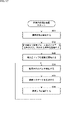
- this process is started when the camera 11 starts imaging, and ends when the camera 11 finishes imaging.
- step S61 the information processing system 1 starts imaging processing. That is, the imaging process similar to that of step S1 in FIG. 5 described above is started.
- step S62 the CCU 15 embeds the video frame and metadata in the output signal and starts the process of outputting.
- the metadata output unit 102 organizes the camera metadata acquired from the camera 11 to generate incidental metadata, and starts the process of supplying it to the output unit 54 .
- the output unit 54 arranges (adds) the video frame and accompanying metadata to an output signal of a predetermined format, and starts the process of outputting it to the monitor 17 .
- step S63 the recognition unit 131 of the CCU 15 starts updating the feature point map. Specifically, the recognition unit 131 detects the feature points of the video frame, and based on the detection result, starts the process of updating the feature point map indicating the distribution of the feature points around the camera 11 .
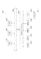
- FIG. 18 shows an example of a feature point map.
- the cross marks in the drawing indicate the positions of feature points.
- the recognition unit 131 generates a feature point map indicating the positions and feature quantity vectors of the feature points of the scene around the camera 11 by connecting the detection results of the feature points of the video frames captured around the camera 11. and update.
- the position of a feature point is represented by, for example, a direction based on the reference direction of the camera 11 and a distance in the depth direction.
- step S64 the recognition unit 131 of the CCU 15 detects deviation in the imaging direction. Specifically, the recognition unit 131 detects the imaging direction of the camera 11 by matching the feature points detected from the video frame and the feature point map.
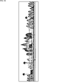
- FIG. 19 shows an example of a video frame when the camera 11 faces the reference direction.
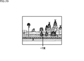
- FIG. 20 shows an example of a video frame when the camera 11 is oriented at ⁇ 7 degrees (7 degrees counterclockwise) from the reference direction in the panning direction.
- the recognition unit 131 detects the imaging direction of the camera 11 by matching the feature points of the feature point map of FIG. 18 and the feature points of the video frame of FIG. 19 or 20 .
- the recognition unit 131 detects the difference between the imaging direction detected based on the video frame and the imaging direction detected by the camera 11 using the motion sensor 32 as a deviation in the imaging direction. That is, the detected deviation corresponds to an accumulated error caused by cumulative calculation of angular velocities detected by the motion sensor 32 by the imaging direction detection unit 72 of the camera 11 .
- step S65 the CCU 15 generates recognition metadata.
- the recognition metadata generation unit 132 generates recognition metadata including data based on the detected shift in the imaging direction.
- the recognition metadata generation unit 132 calculates a correction value for the reference direction based on the detected shift in the imaging direction, and generates recognition metadata including the correction value for the reference direction.
- the recognition metadata generation unit 132 supplies the generated recognition metadata to the CPU 52 .
- the metadata output unit 102 outputs recognition metadata to the camera 11 .
- step S66 the imaging direction detection unit 72 of the camera 11 corrects the reference direction based on the reference direction correction value included in the recognition metadata.
- the imaging direction detection unit 72 continuously corrects the reference direction in a plurality of times using, for example, ⁇ -blending (IIR (Infinite Impulse Response) processing). As a result, the reference direction changes gradually and smoothly.
- IIR Infinite Impulse Response
- step S64 After that, the process returns to step S64, and the processes after step S64 are executed.
- the camera 11 corrects the reference direction based on the result of the video frame recognition processing by the CCU 15 .
- the delay in correcting the deviation of the image pickup direction of the camera 11 is shortened compared to the case where the CCU 15 directly corrects the image pickup direction using recognition processing that requires processing time.
- This process is started, for example, when the user uses the operation panel 16 to input an instruction to start the subject recognition/embedding process, and ends when the user inputs an instruction to stop the subject recognition/embedding process.
- step S81 imaging processing is performed in the same manner as the processing in step S1 of FIG.
- step S82 the recognition unit 131 of the CCU 15 performs subject recognition.
- the recognition unit 131 recognizes the position, type, and action of each object in the video frame by performing object recognition and action recognition on the video frame.
- step S83 the CCU 15 generates recognition metadata.
- the recognition metadata generation unit 132 generates recognition metadata including the position, type, and action of each object recognized by the recognition unit 131 and supplies the recognition metadata to the CPU 52 .
- the metadata output unit 102 generates incidental metadata based on the camera metadata acquired from the camera 11 and the recognition metadata acquired from the recognition metadata generation unit 132 .
- the incidental metadata includes, for example, imaging direction information, lens information, and control information of the camera 11, as well as the position, type, and action recognition result of each object in the video frame.
- the metadata output unit 102 supplies additional metadata to the output unit 54 .
- step S84 the output unit 54 embeds the video frame and metadata in the output signal and outputs the signal. Specifically, the output unit 54 arranges (adds) the video frame and accompanying metadata to an output signal in a predetermined format, and outputs the signal to the monitor 17 .
- the monitor 17 displays the image in FIG. 22, for example, based on the output signal.
- the image in FIG. 22 is the image in FIG. 10 superimposed with information indicating the position, type, and action recognition result of the object included in the additional metadata.
- the positions of the person, golf club, ball, and mountain in the video are displayed. Also, as the action of the person, it is indicated that the player is making a tee shot.
- step S81 After that, the process returns to step S81, and the processes after step S81 are executed.
- metadata including the result of object recognition for video frames can be embedded in the output signal in real time without human intervention.
- FIG. 22 it is possible to quickly present the result of object recognition.
- the CCU 15 performs recognition processing on video frames while the camera 11 is imaging, and the camera 11 and the monitor 17 outside the CCU 15 can use the results of the recognition processing in real time.
- the viewfinder 23 of the camera 11 can superimpose information based on the result of the recognition process on the through-the-lens image and display it in real time.
- the monitor 17 can superimpose the information based on the result of the recognition processing on the image based on the image frame and display it in real time, or display the masked image in real time. This improves operability for users such as photographers and VEs.
- the camera 11 can correct the detection result of the imaging direction in real time based on the correction value of the reference direction obtained by the recognition process. This improves the detection accuracy of the imaging direction.
- ⁇ Modified Example of Sharing of Processing> it is possible to change the sharing of processing between the camera 11 and the CCU 15 .
- the camera 11 may execute part or all of the processing of the information processing section 53 of the CCU 15 .
- the camera 11 executes all the processing of the information processing unit 53, the processing load on the camera 11 increases, the housing of the camera 11 becomes large, and the power consumption and heat generation of the camera 11 increase. increase. An increase in the size of the housing of the camera 11 and an increase in heat generation are undesirable because they hinder the routing of cables of the camera 11 . Further, for example, when the information processing system 1 performs signal processing by the Baseband Processing Unit by 4K/8K shooting, high frame rate shooting, etc., the camera 11 develops the entire video frame like the information processing unit 53. , it is difficult to perform the recognition process.
- a device such as a PC (Personal Computer) or a server in the latter stage of the CCU 15 to execute the processing of the information processing section 53 .
- the CCU 15 outputs the video frames and camera metadata to the subsequent device, and the latter device needs to perform the above-described recognition processing and the like to generate recognition metadata and output it to the CCU 15 .
- processing delays and securing of transmission bands between the CCU 15 and subsequent devices become issues.
- the information processing unit 53 is transferred to the CCU 15 as described above. It is best to have
- the output unit 54 may output the additional metadata in association with the output signal without embedding it in the output signal.
- the recognition metadata generation unit 132 of the CCU 15 may generate recognition metadata containing detection values of deviation in the imaging direction instead of correction values in the reference direction as data used for correction in the reference direction. Then, the imaging direction detection unit 72 of the camera 11 may correct the reference direction based on the detection value of deviation in the imaging direction.
- the series of processes described above can be executed by hardware or by software.
- a program that constitutes the software is installed in the computer.
- the computer includes, for example, a computer built into dedicated hardware and a general-purpose personal computer capable of executing various functions by installing various programs.
- FIG. 23 is a block diagram showing an example of the hardware configuration of a computer that executes the series of processes described above by a program.
- CPU Central Processing Unit
- ROM Read Only Memory
- RAM Random Access Memory
- An input/output interface 1005 is further connected to the bus 1004 .
- An input unit 1006 , an output unit 1007 , a recording unit 1008 , a communication unit 1009 and a drive 1010 are connected to the input/output interface 1005 .
- the input unit 1006 consists of input switches, buttons, a microphone, an imaging device, and the like.
- the output unit 1007 includes a display, a speaker, and the like.
- a recording unit 1008 includes a hard disk, a nonvolatile memory, and the like.
- a communication unit 1009 includes a network interface and the like.
- a drive 1010 drives a removable medium 1011 such as a magnetic disk, optical disk, magneto-optical disk, or semiconductor memory.
- the CPU 1001 loads, for example, a program recorded in the recording unit 1008 into the RAM 1003 via the input/output interface 1005 and the bus 1004, and executes the program. A series of processes are performed.
- the program executed by the computer 1000 can be provided by being recorded on removable media 1011 such as package media, for example. Also, the program can be provided via a wired or wireless transmission medium such as a local area network, the Internet, or digital satellite broadcasting.
- the program can be installed in the recording unit 1008 via the input/output interface 1005 by loading the removable medium 1011 into the drive 1010 . Also, the program can be received by the communication unit 1009 and installed in the recording unit 1008 via a wired or wireless transmission medium. In addition, programs can be installed in the ROM 1002 and the recording unit 1008 in advance.
- the program executed by the computer may be a program that is processed in chronological order according to the order described in this specification, or may be executed in parallel or at a necessary timing such as when a call is made. It may be a program in which processing is performed.
- a system means a set of multiple components (devices, modules (parts), etc.), and it does not matter whether all the components are in the same housing. Therefore, a plurality of devices housed in separate housings and connected via a network, and a single device housing a plurality of modules in one housing, are both systems. .
- this technology can take the configuration of cloud computing in which one function is shared by multiple devices via a network and processed jointly.
- each step described in the flowchart above can be executed by a single device, or can be shared by a plurality of devices.
- one step includes multiple processes
- the multiple processes included in the one step can be executed by one device or shared by multiple devices.
- the imaging device is a display unit that displays a through image;
- the recognition unit calculates a focus index value for a subject of a predetermined type recognized by the subject recognition
- the recognition metadata further includes the focus index value
- the display control unit superimposes an image indicating the position of the subject and the focus index value for the subject on the through-the-lens image.
- Information processing system (5) The information processing system according to (4), wherein the display control unit superimposes an image indicating the position of the subject and the focus index value on the through-the-lens image in different display modes for each subject.
- (6) The information processing according to any one of (3) to (5), wherein the display control unit performs peaking highlighting display of the live view limited to a region of a subject of a predetermined type based on the recognition metadata. system.
- the imaging device is an imaging direction detection unit that detects an imaging direction of the imaging device based on a predetermined reference direction; a camera metadata generation unit that generates camera metadata including the detected imaging direction and outputs the camera metadata to the information processing device;
- the recognizing unit detects deviation of the imaging direction included in the camera metadata based on the captured image,
- the information processing system according to any one of (1) to (6), wherein the recognition metadata includes data based on the detected deviation of the imaging direction.
- the recognition metadata generation unit generates the recognition metadata including data used for correcting the reference direction based on the detected shift in the imaging direction, The information processing system according to (7), wherein the imaging direction detection unit corrects the reference direction based on the recognition metadata.
- An information processing device that controls an imaging device that captures a captured image, Performing recognition processing on the captured image, generating recognition metadata including data based on results of the recognition process; An information processing method for outputting the recognition metadata to the imaging device.
- an imaging device that captures a captured image; and an information processing device that controls the imaging device The information processing device is a recognition unit that performs recognition processing on the captured image; a recognition metadata generation unit that generates recognition metadata including data based on the result of the recognition processing; and an output unit that outputs the recognition metadata to a subsequent device.
- the recognition unit performs at least one of subject recognition and area recognition in the captured image,
- the information processing system according to (10) wherein the recognition metadata includes at least one of a result of subject recognition and a result of area recognition.
- the ( 11) The information processing system described in 11).
- the mask processing unit reduces a chroma component of the mask region and compresses a contrast of a luminance component of the mask region.
- the output unit adds at least part of the recognition metadata to an output signal including the captured image, and outputs the output signal to the subsequent device. information processing system.
- the imaging device is a camera metadata generation unit that generates camera metadata including a detection result of the imaging direction of the imaging device and outputs it to the information processing device;
- the camera metadata further includes at least one of control information of the imaging device and lens information regarding a lens of the imaging device.
- An information processing device that controls an imaging device that captures a captured image, Performing recognition processing on the captured image, generating recognition metadata including data based on results of the recognition process; An information processing method for outputting the recognition metadata to a subsequent device.
- a recognition unit that performs recognition processing on a captured image captured by an imaging device; a recognition metadata generation unit that generates recognition metadata including data based on the result of the recognition processing; and an output unit that outputs the recognition metadata.
- the output unit outputs the recognition metadata to the imaging device.
- the output unit outputs the recognition metadata to a subsequent device.
Landscapes
- Engineering & Computer Science (AREA)
- Multimedia (AREA)
- Signal Processing (AREA)
- General Physics & Mathematics (AREA)
- Physics & Mathematics (AREA)
- Theoretical Computer Science (AREA)
- Computer Vision & Pattern Recognition (AREA)
- Health & Medical Sciences (AREA)
- General Health & Medical Sciences (AREA)
- Psychiatry (AREA)
- Social Psychology (AREA)
- Human Computer Interaction (AREA)
- Studio Devices (AREA)
Abstract
Description
1.実施の形態
2.変形例
3.その他
図1乃至図22を参照して、本技術の実施の形態について説明する。
図1は、本技術を適用した情報処理システム1の一実施の形態を示すブロック図である。
図2は、カメラ11のCPU33により実現される機能の構成例を示している。例えば、CPU33が所定の制御プログラムを実行することにより、制御部71、撮像方向検出部72、カメラメタデータ生成部73、及び、表示制御部74を含む機能が実現される。
図3は、CCU15のCPU52により実現される機能の構成例を示している。例えば、CPU52が所定の制御プログラムを実行することにより、制御部101及びメタデータ出力部102を含む機能が実現される。
図4は、CCU15の情報処理部53の構成例を示している。情報処理部53は、認識部131及び認識メタデータ生成部132を備える。
次に、情報処理システム1の処理について説明する。
まず、図5のフローチャートを参照して、情報処理システム1により実行される合焦指標表示処理について説明する。
次に、図7のフローチャートを参照して、情報処理システム1により実行されるピーキング強調表示処理について説明する。
次に、図9のフローチャートを参照して、情報処理システム1により実行される映像マスク処理について説明する。
次に、図17のフローチャートを参照して、情報処理システム1により実行される基準方向補正処理について説明する。
次に、図21のフローチャートを参照して、情報処理システム1により実行される被写体認識・メタデータ埋め込み処理について説明する。
以上のようにして、CCU15が、カメラ11の撮像中に映像フレームに対する認識処理を行い、CCU15の外部のカメラ11及びモニタ17が、認識処理の結果をリアルタイムに利用することが可能になる。
以下、上述した本技術の実施の形態の変形例について説明する。
例えば、カメラ11とCCU15の処理の分担を変更することが可能である。例えば、カメラ11が、CCU15の情報処理部53の処理の一部又は全部を実行するようにしてもよい。
例えば、出力部54が、付帯メタデータを出力信号に埋め込まずに、出力信号と対応付けて出力するようにしてもよい。
<コンピュータの構成例>
上述した一連の処理は、ハードウエアにより実行することもできるし、ソフトウエアにより実行することもできる。一連の処理をソフトウエアにより実行する場合には、そのソフトウエアを構成するプログラムが、コンピュータにインストールされる。ここで、コンピュータには、専用のハードウエアに組み込まれているコンピュータや、各種のプログラムをインストールすることで、各種の機能を実行することが可能な、例えば汎用のパーソナルコンピュータなどが含まれる。
本技術は、以下のような構成をとることもできる。
撮像画像の撮像を行う撮像装置と、
前記撮像装置の制御を行う情報処理装置と
を備え、
前記情報処理装置は、
前記撮像画像に対して認識処理を行う認識部と、
前記認識処理の結果に基づくデータを含む認識メタデータを生成する認識メタデータ生成部と、
前記認識メタデータを前記撮像装置に出力する出力部と
を備える情報処理システム。
(2)
前記認識部は、前記撮像画像内の被写体認識及び領域認識のうち少なくとも1つを行い、
前記認識メタデータは、前記被写体認識の結果及び前記領域認識の結果のうち少なくとも1つを含む
前記(1)に記載の情報処理システム。
(3)
前記撮像装置は、
スルー画を表示する表示部と、
前記認識メタデータに基づいて、前記スルー画の表示を制御する表示制御部と
を備える前記(2)に記載の情報処理システム。
(4)
前記認識部は、前記被写体認識により認識した所定の種別の被写体に対する合焦指標値を算出し、
前記認識メタデータは、前記合焦指標値をさらに含み
前記表示制御部は、前記被写体の位置を示す画像及び前記被写体に対する前記合焦指標値を前記スルー画に重畳させる
前記(3)に記載の情報処理システム。
(5)
前記表示制御部は、前記被写体の位置を示す画像及び前記合焦指標値を前記被写体毎に異なる表示態様で前記スルー画に重畳させる
前記(4)に記載の情報処理システム。
(6)
前記表示制御部は、前記認識メタデータに基づいて、所定の種別の被写体の領域に限定して前記スルー画のピーキング強調表示を行う
前記(3)乃至(5)のいずれかに記載の情報処理システム。
(7)
前記撮像装置は、
所定の基準方向を基準とする前記撮像装置の撮像方向を検出する撮像方向検出部と、
検出された前記撮像方向を含むカメラメタデータを生成し、前記情報処理装置に出力するカメラメタデータ生成部と
を備え、
前記認識部は、前記撮像画像に基づいて、前記カメラメタデータに含まれる前記撮像方向のズレを検出し、
前記認識メタデータは、検出された前記撮像方向のズレに基づくデータを含む
前記(1)乃至(6)のいずれかに記載の情報処理システム。
(8)
前記認識メタデータ生成部は、検出された前記撮像方向のズレに基づいて、前記基準方向の補正に用いるデータを含む前記認識メタデータを生成し、
前記撮像方向検出部は、前記認識メタデータに基づいて、前記基準方向を補正する
前記(7)に記載の情報処理システム。
(9)
撮像画像の撮像を行う撮像装置の制御を行う情報処理装置が、
前記撮像画像に対して認識処理を行い、
前記認識処理の結果に基づくデータを含む認識メタデータを生成し、
前記認識メタデータを前記撮像装置に出力する
情報処理方法。
(10)
撮像画像の撮像を行う撮像装置と、
前記撮像装置の制御を行う情報処理装置と
を備え、
前記情報処理装置は、
前記撮像画像に対して認識処理を行う認識部と、
前記認識処理の結果に基づくデータを含む認識メタデータを生成する認識メタデータ生成部と、
前記認識メタデータを後段の装置に出力する出力部と
を備える情報処理システム。
(11)
前記認識部は、前記撮像画像内の被写体認識及び領域認識のうち少なくとも1つを行い、
前記認識メタデータは、前記被写体認識の結果及び前記領域認識の結果のうち少なくとも1つを含む
前記(10)に記載の情報処理システム。
(12)
前記撮像画像の所定の種別の被写体の領域以外の領域であるマスク領域に対してマスク処理を行い、前記マスク処理後の前記撮像画像を前記後段の装置に出力するマスク処理部を
さらに備える前記(11)に記載の情報処理システム。
(13)
前記マスク処理部は、前記マスク領域のクロマ成分を低減し、前記マスク領域の輝度成分のコントラストを圧縮する
前記(12)に記載の情報処理システム。
(14)
前記出力部は、前記撮像画像を含む出力信号に前記認識メタデータの少なくとも一部を付加して、前記出力信号を前記後段の装置に出力する
前記(10)乃至(13)のいずれかに記載の情報処理システム。
(15)
前記撮像装置は、
前記撮像装置の撮像方向の検出結果を含むカメラメタデータを生成し、前記情報処理装置に出力するカメラメタデータ生成部を
備え、
前記出力部は、前記カメラメタデータの少なくとも一部をさらに前記出力信号に付加する
前記(14)に記載の情報処理システム。
(16)
前記カメラメタデータは、前記撮像装置の制御情報及び前記撮像装置のレンズに関するレンズ情報のうち少なくとも1つをさらに含む
前記(15)に記載の情報処理システム。
(17)
撮像画像の撮像を行う撮像装置の制御を行う情報処理装置が、
前記撮像画像に対して認識処理を行い、
前記認識処理の結果に基づくデータを含む認識メタデータを生成し、
前記認識メタデータを後段の装置に出力する
情報処理方法。
(18)
撮像装置により撮像された撮像画像に対して認識処理を行う認識部と、
前記認識処理の結果に基づくデータを含む認識メタデータを生成する認識メタデータ生成部と、
前記認識メタデータを出力する出力部と
を備える情報処理装置。
(19)
前記出力部は、前記撮像装置に前記認識メタデータを出力する
前記(18)に記載の情報処理装置。
(20)
前記出力部は、後段の装置に前記認識メタデータを出力する
前記(18)又は(19)に記載の情報処理装置。
Claims (20)
- 撮像画像の撮像を行う撮像装置と、
前記撮像装置の制御を行う情報処理装置と
を備え、
前記情報処理装置は、
前記撮像画像に対して認識処理を行う認識部と、
前記認識処理の結果に基づくデータを含む認識メタデータを生成する認識メタデータ生成部と、
前記認識メタデータを前記撮像装置に出力する出力部と
を備える情報処理システム。 - 前記認識部は、前記撮像画像内の被写体認識及び領域認識のうち少なくとも1つを行い、
前記認識メタデータは、前記被写体認識の結果及び前記領域認識の結果のうち少なくとも1つを含む
請求項1に記載の情報処理システム。 - 前記撮像装置は、
スルー画を表示する表示部と、
前記認識メタデータに基づいて、前記スルー画の表示を制御する表示制御部と
を備える請求項2に記載の情報処理システム。 - 前記認識部は、前記被写体認識により認識した所定の種別の被写体に対する合焦指標値を算出し、
前記認識メタデータは、前記合焦指標値をさらに含み
前記表示制御部は、前記被写体の位置を示す画像及び前記被写体に対する前記合焦指標値を前記スルー画に重畳させる
請求項3に記載の情報処理システム。 - 前記表示制御部は、前記被写体の位置を示す画像及び前記合焦指標値を前記被写体毎に異なる表示態様で前記スルー画に重畳させる
請求項4に記載の情報処理システム。 - 前記表示制御部は、前記認識メタデータに基づいて、所定の種別の被写体の領域に限定して前記スルー画のピーキング強調表示を行う
請求項3に記載の情報処理システム。 - 前記撮像装置は、
所定の基準方向を基準とする前記撮像装置の撮像方向を検出する撮像方向検出部と、
検出された前記撮像方向を含むカメラメタデータを生成し、前記情報処理装置に出力するカメラメタデータ生成部と
を備え、
前記認識部は、前記撮像画像に基づいて、前記カメラメタデータに含まれる前記撮像方向のズレを検出し、
前記認識メタデータは、検出された前記撮像方向のズレに基づくデータを含む
請求項1に記載の情報処理システム。 - 前記認識メタデータ生成部は、検出された前記撮像方向のズレに基づいて、前記基準方向の補正に用いるデータを含む前記認識メタデータを生成し、
前記撮像方向検出部は、前記認識メタデータに基づいて、前記基準方向を補正する
請求項7に記載の情報処理システム。 - 撮像画像の撮像を行う撮像装置の制御を行う情報処理装置が、
前記撮像画像に対して認識処理を行い、
前記認識処理の結果に基づくデータを含む認識メタデータを生成し、
前記認識メタデータを前記撮像装置に出力する
情報処理方法。 - 撮像画像の撮像を行う撮像装置と、
前記撮像装置の制御を行う情報処理装置と
を備え、
前記情報処理装置は、
前記撮像画像に対して認識処理を行う認識部と、
前記認識処理の結果に基づくデータを含む認識メタデータを生成する認識メタデータ生成部と、
前記認識メタデータを後段の装置に出力する出力部と
を備える情報処理システム。 - 前記認識部は、前記撮像画像内の被写体認識及び領域認識のうち少なくとも1つを行い、
前記認識メタデータは、前記被写体認識の結果及び前記領域認識の結果のうち少なくとも1つを含む
請求項10に記載の情報処理システム。 - 前記撮像画像の所定の種別の被写体の領域以外の領域であるマスク領域に対してマスク処理を行い、前記マスク処理後の前記撮像画像を前記後段の装置に出力するマスク処理部を
さらに備える請求項11に記載の情報処理システム。 - 前記マスク処理部は、前記マスク領域のクロマ成分を低減し、前記マスク領域の輝度成分のコントラストを圧縮する
請求項12に記載の情報処理システム。 - 前記出力部は、前記撮像画像を含む出力信号に前記認識メタデータの少なくとも一部を付加して、前記出力信号を前記後段の装置に出力する
請求項10に記載の情報処理システム。 - 前記撮像装置は、
前記撮像装置の撮像方向の検出結果を含むカメラメタデータを生成し、前記情報処理装置に出力するカメラメタデータ生成部を
備え、
前記出力部は、前記カメラメタデータの少なくとも一部をさらに前記出力信号に付加する
請求項14に記載の情報処理システム。 - 前記カメラメタデータは、前記撮像装置の制御情報及び前記撮像装置のレンズに関するレンズ情報のうち少なくとも1つをさらに含む
請求項15に記載の情報処理システム。 - 撮像画像の撮像を行う撮像装置の制御を行う情報処理装置が、
前記撮像画像に対して認識処理を行い、
前記認識処理の結果に基づくデータを含む認識メタデータを生成し、
前記認識メタデータを後段の装置に出力する
情報処理方法。 - 撮像装置により撮像された撮像画像に対して認識処理を行う認識部と、
前記認識処理の結果に基づくデータを含む認識メタデータを生成する認識メタデータ生成部と、
前記認識メタデータを出力する出力部と
を備える情報処理装置。 - 前記出力部は、前記撮像装置に前記認識メタデータを出力する
請求項18に記載の情報処理装置。 - 前記出力部は、後段の装置に前記認識メタデータを出力する
請求項18に記載の情報処理装置。
Priority Applications (4)
| Application Number | Priority Date | Filing Date | Title |
|---|---|---|---|
| CN202280022488.0A CN117015974A (zh) | 2021-03-26 | 2022-01-25 | 信息处理系统、信息处理方法和信息处理设备 |
| US18/281,735 US20240171853A1 (en) | 2021-03-26 | 2022-01-25 | Information processing system, information processing method, and information processing device |
| EP22774628.6A EP4319131A4 (en) | 2021-03-26 | 2022-01-25 | INFORMATION PROCESSING SYSTEM, INFORMATION PROCESSING METHOD AND INFORMATION PROCESSING DEVICE |
| JP2023508707A JP7835217B2 (ja) | 2021-03-26 | 2022-01-25 | 情報処理システム、情報処理方法、及び、情報処理装置 |
Applications Claiming Priority (2)
| Application Number | Priority Date | Filing Date | Title |
|---|---|---|---|
| JP2021-053269 | 2021-03-26 | ||
| JP2021053269 | 2021-03-26 |
Publications (1)
| Publication Number | Publication Date |
|---|---|
| WO2022201826A1 true WO2022201826A1 (ja) | 2022-09-29 |
Family
ID=83395372
Family Applications (1)
| Application Number | Title | Priority Date | Filing Date |
|---|---|---|---|
| PCT/JP2022/002504 Ceased WO2022201826A1 (ja) | 2021-03-26 | 2022-01-25 | 情報処理システム、情報処理方法、及び、情報処理装置 |
Country Status (5)
| Country | Link |
|---|---|
| US (1) | US20240171853A1 (ja) |
| EP (1) | EP4319131A4 (ja) |
| JP (1) | JP7835217B2 (ja) |
| CN (1) | CN117015974A (ja) |
| WO (1) | WO2022201826A1 (ja) |
Families Citing this family (3)
| Publication number | Priority date | Publication date | Assignee | Title |
|---|---|---|---|---|
| JP2024050074A (ja) * | 2022-09-29 | 2024-04-10 | キヤノン株式会社 | 表示制御装置及びその制御方法 |
| JP2024057639A (ja) * | 2022-10-13 | 2024-04-25 | キヤノン株式会社 | 制御装置、表示装置、撮像システム、制御方法、およびプログラム |
| US12423040B2 (en) * | 2022-12-08 | 2025-09-23 | Canon Kabushiki Kaisha | Control apparatus, image pickup system, control method, and storage medium |
Citations (4)
| Publication number | Priority date | Publication date | Assignee | Title |
|---|---|---|---|---|
| JP2000113097A (ja) * | 1998-08-04 | 2000-04-21 | Ricoh Co Ltd | 画像認識装置,画像認識方法及び記憶媒体 |
| JP2015049294A (ja) * | 2013-08-30 | 2015-03-16 | リコーイメージング株式会社 | 撮像装置 |
| JP2015156054A (ja) * | 2014-02-19 | 2015-08-27 | キヤノン株式会社 | 画像処理装置およびその制御方法 |
| JP2015233261A (ja) * | 2014-06-11 | 2015-12-24 | キヤノン株式会社 | 撮像装置及び照合システム |
Family Cites Families (10)
| Publication number | Priority date | Publication date | Assignee | Title |
|---|---|---|---|---|
| US9690168B2 (en) * | 2006-11-20 | 2017-06-27 | Red.Com, Inc. | Focus assist system and method |
| US20130201344A1 (en) * | 2011-08-18 | 2013-08-08 | Qualcomm Incorporated | Smart camera for taking pictures automatically |
| WO2013118535A1 (ja) * | 2012-02-06 | 2013-08-15 | ソニー株式会社 | 撮像制御装置、画像処理装置、撮像制御方法及び画像処理方法 |
| US9542736B2 (en) * | 2013-06-04 | 2017-01-10 | Paypal, Inc. | Evaluating image sharpness |
| JP6720966B2 (ja) * | 2015-04-28 | 2020-07-08 | ソニー株式会社 | 情報処理装置、情報処理方法、およびプログラム |
| US10073531B2 (en) * | 2015-10-07 | 2018-09-11 | Google Llc | Electronic device pose identification based on imagery and non-image sensor data |
| US10580140B2 (en) * | 2016-05-23 | 2020-03-03 | Intel Corporation | Method and system of real-time image segmentation for image processing |
| JP6752681B2 (ja) | 2016-10-19 | 2020-09-09 | キヤノン株式会社 | 表示制御装置、表示制御装置の制御方法及びプログラム並びに記憶媒体 |
| JP7095679B2 (ja) * | 2017-03-07 | 2022-07-05 | ソニーグループ株式会社 | 情報処理装置、支援システム及び情報処理方法 |
| JP7121568B2 (ja) | 2018-07-13 | 2022-08-18 | キヤノン株式会社 | 焦点調節装置、撮像装置、焦点調節方法、及びプログラム |
-
2022
- 2022-01-25 WO PCT/JP2022/002504 patent/WO2022201826A1/ja not_active Ceased
- 2022-01-25 CN CN202280022488.0A patent/CN117015974A/zh active Pending
- 2022-01-25 EP EP22774628.6A patent/EP4319131A4/en active Pending
- 2022-01-25 US US18/281,735 patent/US20240171853A1/en active Pending
- 2022-01-25 JP JP2023508707A patent/JP7835217B2/ja active Active
Patent Citations (4)
| Publication number | Priority date | Publication date | Assignee | Title |
|---|---|---|---|---|
| JP2000113097A (ja) * | 1998-08-04 | 2000-04-21 | Ricoh Co Ltd | 画像認識装置,画像認識方法及び記憶媒体 |
| JP2015049294A (ja) * | 2013-08-30 | 2015-03-16 | リコーイメージング株式会社 | 撮像装置 |
| JP2015156054A (ja) * | 2014-02-19 | 2015-08-27 | キヤノン株式会社 | 画像処理装置およびその制御方法 |
| JP2015233261A (ja) * | 2014-06-11 | 2015-12-24 | キヤノン株式会社 | 撮像装置及び照合システム |
Non-Patent Citations (1)
| Title |
|---|
| See also references of EP4319131A4 * |
Also Published As
| Publication number | Publication date |
|---|---|
| EP4319131A1 (en) | 2024-02-07 |
| JPWO2022201826A1 (ja) | 2022-09-29 |
| US20240171853A1 (en) | 2024-05-23 |
| CN117015974A (zh) | 2023-11-07 |
| EP4319131A4 (en) | 2024-09-04 |
| JP7835217B2 (ja) | 2026-03-25 |
Similar Documents
| Publication | Publication Date | Title |
|---|---|---|
| KR100886298B1 (ko) | 영상 프로세서 및 영상 처리 프로그램을 기록한 컴퓨터로 읽을 수 있는 기록매체 | |
| US8711230B2 (en) | Image capture apparatus and program | |
| JP7835217B2 (ja) | 情報処理システム、情報処理方法、及び、情報処理装置 | |
| US7860387B2 (en) | Imaging apparatus and control method therefor | |
| CN108028889B (zh) | 图像处理设备、图像处理方法、程序和摄像系统 | |
| EP3836540B1 (en) | Image processing apparatus and image capturing apparatus | |
| US20110311150A1 (en) | Image processing apparatus | |
| US11190703B2 (en) | Image-capturing apparatus, program, and electronic device that controls image sensor based on moving velocity | |
| JP3732665B2 (ja) | 自動焦点制御装置及びその合焦動作決定方法 | |
| CN109714524B (zh) | 摄像装置、系统、摄像装置的控制方法和存储介质 | |
| KR20100060140A (ko) | 영상 처리 장치에서의 광역 역광 보정 영상 획득 장치 및 방법 | |
| JP4869795B2 (ja) | 撮像制御装置、撮像システム、および撮像制御方法 | |
| WO2023189079A1 (ja) | 画像処理装置、および画像処理方法、並びにプログラム | |
| JP2018157479A (ja) | 撮像装置、撮像装置の制御方法、及び、プログラム | |
| US9094601B2 (en) | Image capture device and audio hinting method thereof in focusing | |
| JP2009171428A (ja) | デジタルカメラ装置および電子ズームの制御方法およびプログラム | |
| KR20130059091A (ko) | 디지털 촬영 장치 및 이의 제어 방법 | |
| JP6351335B2 (ja) | 撮像装置、その制御方法、および制御プログラム | |
| US20210258472A1 (en) | Electronic device | |
| JP2010154306A (ja) | 撮像制御装置、撮像制御プログラム及び撮像制御方法 | |
| US20220400215A1 (en) | Image pickup apparatus, image pickup method, and storage medium | |
| US20220408022A1 (en) | Image processing apparatus, image processing method, and storage medium | |
| US11665438B2 (en) | Electronic device capable of acquiring line-of-sight information | |
| JP2005348115A (ja) | 明度補正画像生成装置および明度補正画像生成方式 | |
| KR20110060499A (ko) | 디지털 영상 처리 장치 및 그 제어방법 |
Legal Events
| Date | Code | Title | Description |
|---|---|---|---|
| 121 | Ep: the epo has been informed by wipo that ep was designated in this application |
Ref document number: 22774628 Country of ref document: EP Kind code of ref document: A1 |
|
| WWE | Wipo information: entry into national phase |
Ref document number: 2023508707 Country of ref document: JP |
|
| WWE | Wipo information: entry into national phase |
Ref document number: 18281735 Country of ref document: US |
|
| WWE | Wipo information: entry into national phase |
Ref document number: 202280022488.0 Country of ref document: CN |
|
| WWE | Wipo information: entry into national phase |
Ref document number: 2022774628 Country of ref document: EP |
|
| NENP | Non-entry into the national phase |
Ref country code: DE |
|
| ENP | Entry into the national phase |
Ref document number: 2022774628 Country of ref document: EP Effective date: 20231026 |