WO2022202085A1 - バッテリー駆動モータ及びモータ駆動システム - Google Patents
バッテリー駆動モータ及びモータ駆動システム Download PDFInfo
- Publication number
- WO2022202085A1 WO2022202085A1 PCT/JP2022/007743 JP2022007743W WO2022202085A1 WO 2022202085 A1 WO2022202085 A1 WO 2022202085A1 JP 2022007743 W JP2022007743 W JP 2022007743W WO 2022202085 A1 WO2022202085 A1 WO 2022202085A1
- Authority
- WO
- WIPO (PCT)
- Prior art keywords
- battery
- motor
- driven
- loss
- flux density
- Prior art date
- Legal status (The legal status is an assumption and is not a legal conclusion. Google has not performed a legal analysis and makes no representation as to the accuracy of the status listed.)
- Ceased
Links
Images


Classifications
-
- H—ELECTRICITY
- H02—GENERATION; CONVERSION OR DISTRIBUTION OF ELECTRIC POWER
- H02K—DYNAMO-ELECTRIC MACHINES
- H02K21/00—Synchronous motors having permanent magnets; Synchronous generators having permanent magnets
- H02K21/12—Synchronous motors having permanent magnets; Synchronous generators having permanent magnets with stationary armatures and rotating magnets
- H02K21/14—Synchronous motors having permanent magnets; Synchronous generators having permanent magnets with stationary armatures and rotating magnets with magnets rotating within the armatures
-
- H—ELECTRICITY
- H02—GENERATION; CONVERSION OR DISTRIBUTION OF ELECTRIC POWER
- H02K—DYNAMO-ELECTRIC MACHINES
- H02K29/00—Motors or generators having non-mechanical commutating devices, e.g. discharge tubes or semiconductor devices
- H02K29/03—Motors or generators having non-mechanical commutating devices, e.g. discharge tubes or semiconductor devices with a magnetic circuit specially adapted for avoiding torque ripples or self-starting problems
-
- H—ELECTRICITY
- H01—ELECTRIC ELEMENTS
- H01F—MAGNETS; INDUCTANCES; TRANSFORMERS; SELECTION OF MATERIALS FOR THEIR MAGNETIC PROPERTIES
- H01F1/00—Magnets or magnetic bodies characterised by the magnetic materials therefor; Selection of materials for their magnetic properties
- H01F1/01—Magnets or magnetic bodies characterised by the magnetic materials therefor; Selection of materials for their magnetic properties of inorganic materials
- H01F1/03—Magnets or magnetic bodies characterised by the magnetic materials therefor; Selection of materials for their magnetic properties of inorganic materials characterised by their coercivity
- H01F1/12—Magnets or magnetic bodies characterised by the magnetic materials therefor; Selection of materials for their magnetic properties of inorganic materials characterised by their coercivity of soft-magnetic materials
- H01F1/14—Magnets or magnetic bodies characterised by the magnetic materials therefor; Selection of materials for their magnetic properties of inorganic materials characterised by their coercivity of soft-magnetic materials metals or alloys
- H01F1/147—Alloys characterised by their composition
-
- H—ELECTRICITY
- H01—ELECTRIC ELEMENTS
- H01F—MAGNETS; INDUCTANCES; TRANSFORMERS; SELECTION OF MATERIALS FOR THEIR MAGNETIC PROPERTIES
- H01F41/00—Apparatus or processes specially adapted for manufacturing or assembling magnets, inductances or transformers; Apparatus or processes specially adapted for manufacturing materials characterised by their magnetic properties
- H01F41/02—Apparatus or processes specially adapted for manufacturing or assembling magnets, inductances or transformers; Apparatus or processes specially adapted for manufacturing materials characterised by their magnetic properties for manufacturing cores, coils, or magnets
- H01F41/0206—Manufacturing of magnetic cores by mechanical means
- H01F41/0233—Manufacturing of magnetic circuits made from sheets
-
- H—ELECTRICITY
- H02—GENERATION; CONVERSION OR DISTRIBUTION OF ELECTRIC POWER
- H02K—DYNAMO-ELECTRIC MACHINES
- H02K1/00—Details of the magnetic circuit
- H02K1/02—Details of the magnetic circuit characterised by the magnetic material
-
- H—ELECTRICITY
- H02—GENERATION; CONVERSION OR DISTRIBUTION OF ELECTRIC POWER
- H02K—DYNAMO-ELECTRIC MACHINES
- H02K1/00—Details of the magnetic circuit
- H02K1/06—Details of the magnetic circuit characterised by the shape, form or construction
- H02K1/12—Stationary parts of the magnetic circuit
- H02K1/18—Means for mounting or fastening magnetic stationary parts on to, or to, the stator structures
-
- H—ELECTRICITY
- H02—GENERATION; CONVERSION OR DISTRIBUTION OF ELECTRIC POWER
- H02P—CONTROL OR REGULATION OF ELECTRIC MOTORS, ELECTRIC GENERATORS OR DYNAMO-ELECTRIC CONVERTERS; CONTROLLING TRANSFORMERS, REACTORS OR CHOKE COILS
- H02P21/00—Arrangements or methods for the control of electric machines by vector control, e.g. by control of field orientation
- H02P21/0085—Arrangements or methods for the control of electric machines by vector control, e.g. by control of field orientation specially adapted for high speeds, e.g. above nominal speed
-
- H—ELECTRICITY
- H02—GENERATION; CONVERSION OR DISTRIBUTION OF ELECTRIC POWER
- H02P—CONTROL OR REGULATION OF ELECTRIC MOTORS, ELECTRIC GENERATORS OR DYNAMO-ELECTRIC CONVERTERS; CONTROLLING TRANSFORMERS, REACTORS OR CHOKE COILS
- H02P23/00—Arrangements or methods for the control of AC motors characterised by a control method other than vector control
- H02P23/0086—Arrangements or methods for the control of AC motors characterised by a control method other than vector control specially adapted for high speeds, e.g. above nominal speed
-
- H—ELECTRICITY
- H02—GENERATION; CONVERSION OR DISTRIBUTION OF ELECTRIC POWER
- H02P—CONTROL OR REGULATION OF ELECTRIC MOTORS, ELECTRIC GENERATORS OR DYNAMO-ELECTRIC CONVERTERS; CONTROLLING TRANSFORMERS, REACTORS OR CHOKE COILS
- H02P27/00—Arrangements or methods for the control of AC motors characterised by the kind of supply voltage
- H02P27/04—Arrangements or methods for the control of AC motors characterised by the kind of supply voltage using variable-frequency supply voltage, e.g. inverter or converter supply voltage
- H02P27/06—Arrangements or methods for the control of AC motors characterised by the kind of supply voltage using variable-frequency supply voltage, e.g. inverter or converter supply voltage using DC to AC converters or inverters
-
- H—ELECTRICITY
- H02—GENERATION; CONVERSION OR DISTRIBUTION OF ELECTRIC POWER
- H02K—DYNAMO-ELECTRIC MACHINES
- H02K2213/00—Specific aspects, not otherwise provided for and not covered by codes H02K2201/00 - H02K2211/00
- H02K2213/03—Machines characterised by numerical values, ranges, mathematical expressions or similar information
Definitions
- the present disclosure relates to battery-powered motors and motor drive systems.
- the present disclosure provides high speed battery powered motors and motor drive systems particularly suitable for use in battery powered cordless appliances, electric vehicles (EVs), cutting equipment and drones. Regarding.
- the motor which is driven by the power supply from the battery, is required to be highly efficient and to be able to operate for a long time.
- the weight and size increase.
- the maximum number of revolutions can be increased. necessary. For example, as a method to secure high voltage for high-speed rotation, it is conceivable to install a booster circuit. Sometimes I end up doing it.
- permendur has a relatively high cost, and the supply of Co may become unstable. Therefore, there is a demand for a technology that can optimize the efficiency, dimensions, and weight of the equipment as a whole by using highly available non-oriented electrical steel sheets.
- An object of the present disclosure which was made to solve the above problems, is to provide a battery-powered motor and a motor drive system that achieve high power density without impairing the efficiency of the entire system.
- the inventors of the present disclosure have extensively studied iron core materials having electromagnetic characteristics suitable for high-speed motors.
- the magnetic flux density ( B50 ) at a magnetic field strength of 5000 A/m as a motor iron core material is premised on a motor drive system in which the battery supply current is 3.0 C or more for the maximum motor output requirement.
- the loss in the entire system can be effectively reduced. It was found that it is possible to achieve both output density and efficiency by reducing the power consumption.
- a battery-powered motor includes: A battery-driven motor that drives a load by being supplied with power from a battery via an inverter, The current supplied from the battery is 3.0 C or more when driven at maximum output, Equipped with a stator core using an electromagnetic steel sheet as an iron core material having a magnetic flux density of 1.65 T or more at a magnetic field strength of 5000 A / m and an iron loss of 40.0 W / kg or less at 1 kHz - 1.0 T sine wave excitation. .
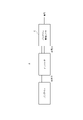
- a motor drive system includes: a battery; an inverter; a battery-driven motor that is supplied with power from the battery via the inverter to drive a load;
- the battery-powered motor is The current supplied from the battery is 3.0 C or more when driven at maximum output, Equipped with a stator core using an electromagnetic steel sheet as an iron core material having a magnetic flux density of 1.65 T or more at a magnetic field strength of 5000 A / m and an iron loss of 40.0 W / kg or less at 1 kHz - 1.0 T sine wave excitation. .
- FIG. 1 is a diagram schematically showing the configuration of a battery-driven motor according to one embodiment of the present disclosure.
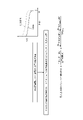
- FIG. 2 is a diagram for explaining the evaluation flow of battery loss and the definition of battery loss Wb.
- FIG. 3 is a diagram showing an example of measurement evaluation results of battery loss in a battery-driven motor.
- FIG. 4 is a diagram showing a configuration example of a battery-driven motor manufactured as an IPM (interior permanent magnet) motor.
- FIG. 5 is a diagram showing a configuration example of a battery-driven motor manufactured as an SPM (surface permanent magnet) motor.
- FIG. 6 is a diagram showing the shape of the manufactured iron core.
- FIG. 1 is a diagram schematically showing the configuration of a battery-driven motor 10 according to one embodiment of the present disclosure.
- the battery-driven motor 10 is powered by a battery via an inverter that converts DC power to AC power to drive a load.
- a battery-driven motor 10, a battery, and an inverter constitute a motor drive system 1, as shown in FIG.
- the motor drive system 1 can be used, for example, in battery-powered equipment such as electric vehicles, vacuum cleaners and drones.
- the battery-driven motor 10 has a load such as a rotating shaft provided in the battery-driven device.
- the magnetic steel sheet that is the core material of the battery-driven motor 10 and the reasons for their limitations will be explained.
- the type of battery-powered motor 10 is not limited.
- the magnetic steel sheet is not limited in composition and manufacturing method as long as the specified magnetic properties are obtained. Further, in the following explanation, the simple indication of "%" for the amount of added component means “% by mass”.
- a steel sheet that satisfies the requirements described below may be selected.
- the supply current from the battery at maximum output is 3.0C or more.
- a power source that can supply power with a large capacity, that is, a high voltage and a large current.
- a booster circuit results in an increase in size and weight. Therefore, in the present embodiment, lithium-ion battery cells are connected in series, in parallel, or in a combination of series and parallel, depending on the voltage required to drive the motor, and current is supplied at a relatively high discharge rate of 3.0 C or higher.
- a configuration that reduces the loss in the entire system.
- a battery loss Wb which will be described later, increases in proportion to the square of this discharge rate (C rate) (see FIG. 3).
- C rate indicates the speed of discharge, and is defined as 1C as the magnitude of the current that completely discharges the nominal capacity of the battery in one hour. For example, 2.0C is the amount of current that will fully discharge the battery's nominal capacity in 0.5 hours.
- the maximum C rate is lower than 3.0C, it is difficult to obtain the effect.
- the number of lithium-ion batteries connected in series may be adjusted according to the required voltage. Also, depending on the required dimensions and continuous drive time of the motor drive system 1, additional lithium ion batteries may be connected in parallel. Lithium-ion batteries are preferred for achieving high energy density and high power density. However, the type of battery is not limited.
- FIG. 2 shows the evaluation flow of the battery loss Wb.
- a CC (constant current) discharge characteristic is evaluated in a charge/discharge device. Specifically, according to the method specified in "JIS C 8711", a constant current discharge at a discharge rate of 0.2C (a current value that reaches the final discharge voltage in 5 hours) and a discharge rate when the motor is driven at the maximum output. A test is conducted. By integrating the curve of the obtained discharge capacity W (Ah) and terminal voltage V (V), the electrical work (Wh) given to the external system by the battery can be calculated.
- the battery loss Wb (W) is calculated from the difference between the voltage drop curves at the C rate of 0.2C and the C rate at the maximum output. Specifically, battery loss Wb (W) at maximum output per unit time is obtained by dividing the difference (energy (Wh) shown in FIG. 2) by the discharge time (h).
- the C rate at the maximum output (maximum C rate) is, for example, 3.0C
- V(C max ) in the equation shown in FIG. 2 is V(3.0C).
- 1/C max of the discharge time is 1/(3.0).
- Fig. 3 shows an example of measurement results of battery loss Wb for a lithium-ion battery with a rated voltage of 21.6V and a rated capacity of 2.8Ah.
- a charge/discharge device PFX2512 manufactured by Kikusui Denshi Kogyo Co., Ltd. was used for the measurement. Any evaluation apparatus may be used as long as a similar constant current discharge test can be performed according to the voltage/current capacity of the evaluation object. Also, since it is difficult to evaluate a large battery pack in which a large number of cells are connected, such as an electric vehicle, a charge/discharge test may be performed by extracting a part or a single cell. As shown in FIG. 3, as the discharge rate increases, the battery loss Wb increases.
- the battery loss Wb is Wm ⁇ Wb with respect to the motor loss Wm (iron loss and copper loss). More preferably, Wm ⁇ 2.0 ⁇ Wb. Therefore, it is preferable to select the core material so as to satisfy such a relationship.
- the magnetic flux density (B 50 ) of the selected iron core material should be 1.65 T or more.
- the magnetic flux density (B 50 ) is the magnetic flux density at a magnetic field strength of 5000 A/m. There is no particular upper limit of the range.
- the magnetic flux density (B 600 ) is preferably 1.95 T or more because it effectively contributes to high torque (that is, low current) in a state where the iron core material is close to magnetic saturation, especially when the motor is driven at maximum output. . More preferably, it is 2.00 T or more.
- the magnetic flux density (B 600 ) is the magnetic flux density at a magnetic field strength of 60000 A/m.
- iron loss (W 10/1000 ) is an effective indicator of iron loss reduction during motor driving. Therefore, the iron loss (W 10/1000 ) of the selected iron core material should be 40.0 W/kg or less. More preferably, it is 30.0 W/kg or less.
- the iron loss (W 10/1000 ) is the iron loss in sinusoidal excitation of 1 kHz-1.0T.
- the electrical steel sheet there are no other restrictions on the electrical steel sheet as long as the above magnetic properties are achieved.
- the composition of the magnetic steel sheet and the difference in manufacturing method do not affect the effect.
- the insulating coating there is no particular limitation as long as at least one surface is provided with a known insulating coating.
- the application of a Co-Fe alloy (magnetic flux density B50 of 2.3 T or more) such as permendur which is known as a soft magnetic material with a high magnetic flux density, is assumed to be applied because the material cost is high and availability is poor.
- the thickness of the magnetic steel sheet there are no restrictions on the thickness of the magnetic steel sheet, but it can be selected as appropriate to satisfy the above iron loss.
- a core material containing Si can be selected.
- the material grades of electrical steel sheets there is often a trade-off between magnetic flux density and iron loss. Since it is possible to reduce the iron loss at high frequencies, it is relatively easy to achieve both high magnetic flux density and low iron loss.
- the processing and lamination methods of the electromagnetic steel sheets but a high lamination factor is preferable in order to effectively obtain an increase in motor torque (reduction in current) due to the high magnetic flux density characteristics of the material.
- an electromagnetic steel sheet is cut into a desired motor core shape by laser processing, vacuum impregnated into an epoxy adhesive while applying pressure in the stacking direction, and work-hardened to obtain a space factor of 90% or more, which is preferable.
- maximum motor speed As described above, increasing the rotation speed is an effective means for increasing the output density of the motor, so it is preferable to set the maximum rotation speed to 10000 rpm or more.
- the rotation speed may be further increased according to the degree of demand for miniaturization and high speed, or according to the voltage value that can be supplied, and the maximum rotation speed is more preferably 20000 rpm or more.
- the maximum rotation speed is more preferably 50000 rpm or more.
- the iron core material is preferably selected so that the output (kW) with respect to the iron core weight (kg) of the motor exceeds 5 kW/kg. More preferably, it is 7 kW/kg. More preferably, it is 10 kW/kg.
- the motor type of the battery-driven motor 10 is not limited, and effects can be obtained with any type.
- an SPM (surface permanent magnet) motor using a magnet or an IPM motor is preferable in terms of increasing the output density of the motor and achieving high efficiency.
- Example 1 An IPM motor having the shape shown in FIG. 4 was manufactured using the magnetic steel sheets shown in Table 1 as core materials.
- the fabricated IPM motor comprises rotor core 11 , stator core 12 , shaft 13 and magnet 14 .
- the iron core was processed by punching with a die and lamination by caulking.
- a magnet 14 was inserted into the obtained rotor core 11 and a winding was applied to the stator core 12 .
- 200 lithium-ion battery cells (3.6V) were provided to power the IPM motor.
- a battery with a total voltage of 360 V was obtained by connecting 2 in parallel of 100 cells connected in series.
- the battery and motor are controlled by a motor drive system 1 that includes an inverter, and the current supplied from the battery at maximum motor output is 4.0C.
- a motor drive system 1 that includes an inverter
- the current supplied from the battery at maximum motor output is 4.0C.
- the battery loss Wb at 4.0C was 10W. That is, the battery loss Wb for the entire battery (200 cells) was 2 kW.
- Table 2 shows the results of evaluating the output and motor loss Wm when operating the manufactured IPM motor at the maximum output (18000 rpm).
- the motor of the example using the core material A having the magnetic properties within the predetermined range has a large maximum output, and the motor has a high maximum output density (kW/kg) with respect to the weight of the motor core.
- the predetermined range means that the magnetic flux density (B 50 ) is 1.65 T or more at a magnetic field strength of 5000 A/m and the iron loss (W 10/1000 ) is 40 at sinusoidal excitation of 1 kHz-1.0 T. .0 W/kg or less.
- Table 3 shows the results of measuring the time from the battery fully charged state to the motor stopping and the battery temperature immediately after stopping when the same motor was driven at a motor output of 12 kW (10000 rpm).
- the example using the core material A has a continuous operation time longer by 10% or more than the comparative example using the core material B and the core material C, and is extremely excellent as a motor for battery-powered equipment. .
- a reduction of 10° C. or more is achieved with respect to the battery temperature after the motor is stopped in the example. This is due to the reduction of battery loss, and it is expected that it will not only reduce the risk of failure due to thermal runaway of the battery, but also have a positive effect on cycle characteristics due to repeated use.
- an SPM motor having the shape shown in FIG. 5 was manufactured using the magnetic steel sheets shown in Table 4 as iron core materials.
- Core materials A to C are the same as above.
- core material D a new electromagnetic steel sheet different from core materials A to C was used.
- the iron core was processed by punching with a die and lamination by caulking.
- the resulting rotor core consisted of a shaft and magnets, and the stator core was wound. These were assembled to produce an SPM motor. A lithium-ion battery cell (3.6 V) was also provided to power the SPM motor. Seven of these cells were connected in series (7 series) or 2 of the 7 series were connected in parallel (7 series ⁇ 2 parallel) to obtain a battery with a total voltage of 25.2V.
- the battery and motor are controlled by a motor drive system 1 that includes an inverter, and the current supplied from the battery at the maximum output of the motor is 6.0C when 7 series are connected in series, and 3.0C when 7 series are connected in parallel with 2.
- the battery loss Wb at 6.0C was 20W. That is, the battery loss Wb for the entire battery (7 cells) was 140W.
- the battery loss at 3.0C was 5W. That is, the battery loss Wb for the entire battery (14 cells) was 70W.
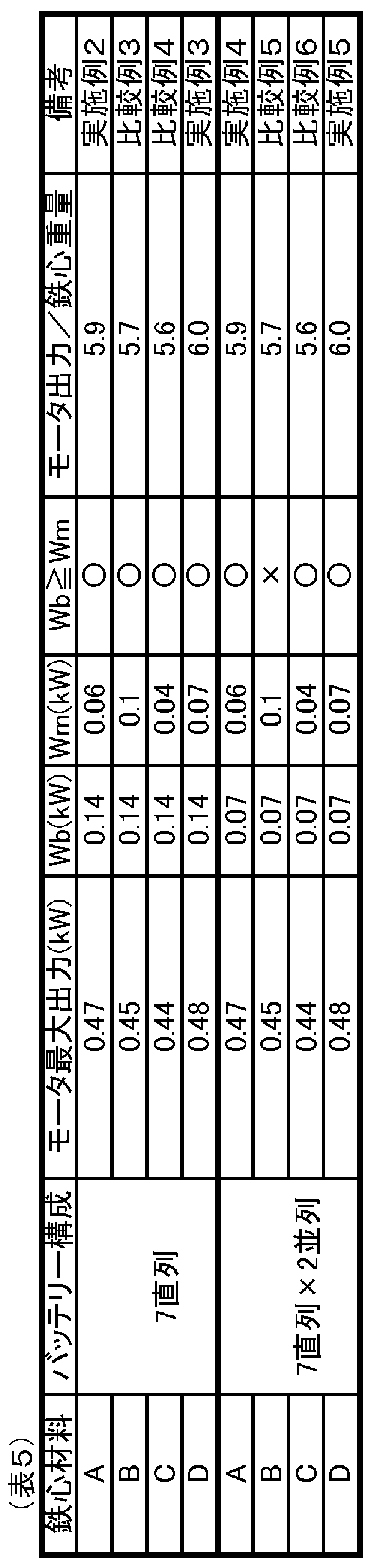
- Table 5 shows the results of evaluating the output and motor loss Wm when operating the manufactured SPM motor at the maximum output (100,000 rpm).
- the motor of the embodiment using the core materials A and D having magnetic properties within the predetermined range has a large maximum output, and the motor has a high maximum output density with respect to the weight of the motor core.
- the predetermined range means that the magnetic flux density (B 50 ) is 1.65 T or more at a magnetic field strength of 5000 A/m and the iron loss (W 10/1000 ) is 40 at sinusoidal excitation of 1 kHz-1.0 T. .0 W/kg or less.
- Table 6 shows the results of measuring the time from the battery fully charged state until the motor stops and the battery temperature immediately after stopping when the same motor is driven at a motor output of 0.4 kW (90,000 rpm).
- the examples using core materials A and D have a longer continuous operation time than the comparative examples using core materials B and C, and are extremely excellent as motors for battery-powered equipment.
- a reduction in the battery temperature after the motor stops in the example is achieved. This is due to the reduction of battery loss, and it is expected that it will not only reduce the risk of failure due to thermal runaway of the battery, but also have a positive effect on cycle characteristics due to repeated use.
- the battery configuration is seven series and the C rate is higher (Examples 2 and 3), compared with the comparative examples (Comparative examples 3 and 4)
- the continuous operation time was extended by nearly 10%, and the battery temperature after the motor was stopped was also lowered by nearly 10°C.
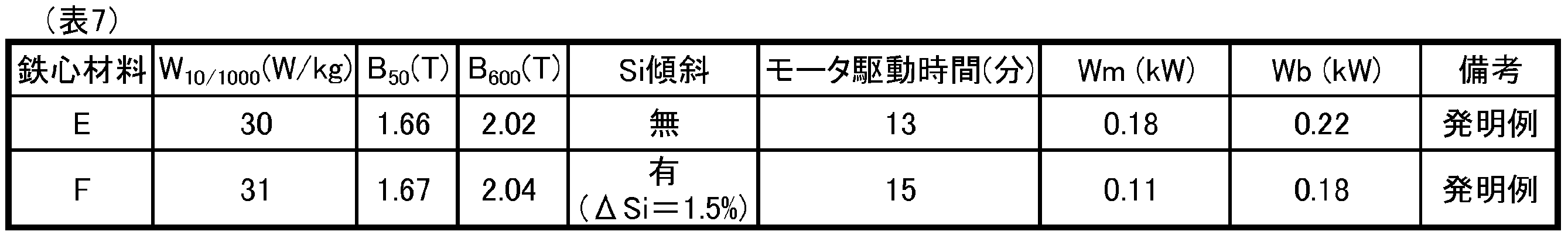
- a core having the shape shown in FIG. 6 was manufactured.
- the motor type is a 14-pole outer rotor SPM.
- the iron core weight is 35 g.
- the iron core was laminated to a height of 10.5 mm by adhesive lamination to form a motor core. Insulating coating and winding were applied to the obtained motor core, and the motor was assembled.
- Four lithium ion battery cells (3.7 V) were connected in series to supply power to the motor, and a battery with a total voltage of 14.8 V was obtained.
- Table 7 also shows the results of evaluating the time until the motor drive can no longer be maintained by continuously driving the motor at 10000 rpm-0.31 Nm (325 W) for such a motor drive system.
- Both core materials E and F are invention examples, and are materials having substantially the same magnetic properties. However, the core materials E and F are different in the presence or absence of the inclination of the Si component in the plate thickness direction. Although the magnetic properties are almost the same, the motor driving time of the iron core material F is improved by about 15%, and it can be seen that an excellent motor system can be constructed when the Si inclination is present in the plate thickness direction. This result is considered to be due to the effect of suppressing deterioration when the core material is processed into the core by having the Si inclination.
- the material having the Si gradient suppresses the adverse effect on the magnetic properties of the stress applied to the motor core by the insulating coating and windings. From the above, in the battery-driven motor of the present disclosure, having a Si gradient not only makes it easier to satisfy the magnetic properties required as a material, but also effectively improves the performance of the entire system when assembled as a motor. do.
- the battery-driven motor 10 and the motor drive system 1 according to the present embodiment can effectively reduce the loss in the entire system and achieve both output density and efficiency due to the above configuration. That is, the battery-driven motor 10 and the motor-driven system 1 according to this embodiment can achieve high power density without impairing the efficiency of the entire system. Also, by applying the battery-driven motor 10 and the motor drive system 1 according to the present embodiment, it is possible to realize compact and highly efficient battery-driven devices such as electric vehicles, vacuum cleaners, and drones.
Landscapes
- Engineering & Computer Science (AREA)
- Power Engineering (AREA)
- Physics & Mathematics (AREA)
- Electromagnetism (AREA)
- Chemical & Material Sciences (AREA)
- Dispersion Chemistry (AREA)
- Manufacturing & Machinery (AREA)
- Iron Core Of Rotating Electric Machines (AREA)
Abstract
Description
インバータを介してバッテリーから電力を供給されて負荷を駆動するバッテリー駆動モータであって、
最大出力での駆動時に、前記バッテリーからの供給電流が3.0C以上であり、
鉄心材料として、磁界の強さが5000A/mにおける磁束密度が1.65T以上かつ1kHz-1.0Tの正弦波励磁における鉄損が40.0W/kg以下である電磁鋼板を用いたステータコアを備える。
バッテリーと、
インバータと、
前記インバータを介して前記バッテリーから電力を供給されて負荷を駆動するバッテリー駆動モータと、を備え、
前記バッテリー駆動モータは、
最大出力での駆動時に、前記バッテリーからの供給電流が3.0C以上であり、
鉄心材料として、磁界の強さが5000A/mにおける磁束密度が1.65T以上かつ1kHz-1.0Tの正弦波励磁における鉄損が40.0W/kg以下である電磁鋼板を用いたステータコアを備える。
モータの高出力密度化には大容量、つまり高電圧かつ大電流での電力供給に対応した電源の適用が有利である。しかしながら、バッテリーからの電力供給で駆動する系では電圧制約が存在し、昇圧回路を具備することは寸法及び重量の増大を招く。そこで、本実施形態では、モータ駆動に必要な電圧に応じて、リチウムイオン電池のセルを直列若しくは並列又は直列と並列を組み合わせて連ねて、3.0C以上という比較的大きな放電レートでの電流供給によってモータの高出力密度化に適した系において、系全体での損失を低減させる構成を提案する。後述するバッテリー損失Wbはこの放電レート(Cレート)の二乗に比例して大きくなる(図3参照)。しかし、本実施形態の構成を適用することで従来技術に比べて電流を低減しバッテリーにおける損失を効果的に低減することが可能となる。ここで、Cレートは、放電のスピードを示し、バッテリーの公称容量を1時間で完全放電させる電流の大きさが1Cと定義される。例えば2.0Cは、バッテリーの公称容量を0.5時間で完全放電させる電流の大きさである。バッテリーの最大放電条件のCレート値が高いほどバッテリーにおける損失としては大きくなるが、この値が高いほどモータは高出力密度なものが得られ、本発明の技術を適用することによる系全体での損失改善の効果が得られやすい。よって、好ましくは5.0C以上であり、さらに好ましくは8.0C以上である。一方で、最大Cレートが3.0Cよりも低い場合には効果が得られにくい。
図2はバッテリー損失Wbの評価フローを示す。まず、充放電装置にてCC(定電流)放電特性が評価される。詳細に述べると、「JIS C 8711」に示されている方法にて、0.2C(5時間で放電終止電圧に至る電流値)及びモータ最大出力で駆動する時の放電レートでの定電流放電試験が行われる。得られた放電容量W(Ah)と端子間電圧V(V)のカーブを積分することで、バッテリーが外部の系に与えた電気的仕事量(Wh)が算出できる。そして、0.2C及び最大出力時のCレートにおける電圧降下曲線の差分からバッテリー損失Wb(W)が計算される。具体的に述べると、差分(図2に示されるエネルギー(Wh))を放電時間(h)で除することで、単位時間当たりの最大出力時のバッテリー損失Wb(W)が得られる。ここで、最大出力時のCレート(最大Cレート)が例えば3.0Cの場合には、図2に記載の式におけるV(Cmax)はV(3.0C)である。また、放電時間の1/Cmaxは、1/(3.0)である。
磁束密度(B50)が高い材料ほどモータの高トルク化が得られるので、同一のトルクで比較するとモータ電流を低減できる。そのため、選択される鉄心材料の磁束密度(B50)は1.65T以上とする。ここで、磁束密度(B50)は、磁界の強さが5000A/mにおける磁束密度である。範囲の上限は特になくてよい。また、磁束密度(B600)は、特にモータ最大出力時の駆動で鉄心材料が磁気飽和に近い状態での高トルク化(すなわち低電流化)に有効に寄与するので、1.95T以上が好ましい。さらに好ましくは2.00T以上である。ここで、磁束密度(B600)は、磁界の強さが60000A/mにおける磁束密度である。また、鉄損(W10/1000)は、モータ駆動時の鉄損低減を示す有効な指標である。そのため、選択される鉄心材料の鉄損(W10/1000)は40.0W/kg以下とする。さらに好ましくは30.0W/kg以下である。ここで、鉄損(W10/1000)は、1kHz-1.0Tの正弦波励磁における鉄損である。
上記のように高速回転化はモータの出力密度を高めるのに有効な手段であるため最大回転数を10000rpm以上とすることが好ましい。小型高速化の要求度合いに応じて、あるいは供給可能な電圧値に応じて、さらに高速回転化してよく、最大回転数は、より好ましくは20000rpm以上である。最大回転数は、さらに好ましくは50000rpm以上である。
表1に示す電磁鋼板を鉄心材料として、図4に示す形状のIPMモータが製作された。作製されたIPMモータは、ロータコア11と、ステータコア12と、シャフト13と、磁石14と、を備える。鉄心の加工は金型による打抜き及びカシメによる積層とした。得られたロータコア11には磁石14が挿入されて、ステータコア12には巻線が施された。これらが組み立てられてIPMモータが製作された。また、IPMモータへの電力供給のために、200個のリチウムイオン電池のセル(3.6V)が用意された。このセルを直列に100個接続したものを、2並列で接続して、総電圧が360Vのバッテリーが得られた。


続いて、表4に示す電磁鋼板を鉄心材料として、図5に示す形状のSPMモータが製作された。鉄心材料A~Cは上記と同じである。鉄心材料Dとして、鉄心材料A~Cと異なる新たな電磁鋼板が用いられた。鉄心の加工は金型による打抜き及びカシメによる積層とした。


10 バッテリー駆動モータ
11 ロータコア
12 ステータコア
13 シャフト
14 磁石
Claims (7)
- インバータを介してバッテリーから電力を供給されて負荷を駆動するバッテリー駆動モータであって、
最大出力での駆動時に、前記バッテリーからの供給電流が3.0C以上であり、
鉄心材料として、磁界の強さが5000A/mにおける磁束密度が1.65T以上かつ1kHz-1.0Tの正弦波励磁における鉄損が40.0W/kg以下である電磁鋼板を用いたステータコアを備える、バッテリー駆動モータ。 - 前記バッテリーは、最大出力での駆動時において、前記バッテリー駆動モータのモータ損失Wmに対して、バッテリー損失WbがWm≦Wbとなる、請求項1に記載のバッテリー駆動モータ。
- 前記バッテリーはリチウムイオン電池である、請求項1又は2に記載のバッテリー駆動モータ。
- 最大回転数が10000rpm以上であって、鉄心重量(kg)に対する出力(kW)が5kW/kgを超える、請求項1から3のいずれか一項に記載のバッテリー駆動モータ。
- 前記電磁鋼板は、磁界の強さが60000A/mにおける磁束密度が1.95T以上かつ1kHz-1.0Tの正弦波励磁における鉄損が30.0W/kg以下である、請求項1から4のいずれか一項に記載のバッテリー駆動モータ。
- 前記鉄心材料は板厚方向にSi濃度の分布を有する、請求項1から5のいずれか一項に記載のバッテリー駆動モータ。
- バッテリーと、
インバータと、
前記インバータを介して前記バッテリーから電力を供給されて負荷を駆動するバッテリー駆動モータと、を備え、
前記バッテリー駆動モータは、
最大出力での駆動時に、前記バッテリーからの供給電流が3.0C以上であり、
鉄心材料として、磁界の強さが5000A/mにおける磁束密度が1.65T以上かつ1kHz-1.0Tの正弦波励磁における鉄損が40.0W/kg以下である電磁鋼板を用いたステータコアを備える、モータ駆動システム。
Priority Applications (5)
| Application Number | Priority Date | Filing Date | Title |
|---|---|---|---|
| US18/548,968 US12531462B2 (en) | 2021-03-24 | 2022-02-24 | Battery-driven motor and motor-driven system |
| EP22774883.7A EP4307556A4 (en) | 2021-03-24 | 2022-02-24 | BATTERY POWERED MOTOR AND MOTOR POWERED SYSTEM |
| JP2022534316A JP7599491B2 (ja) | 2021-03-24 | 2022-02-24 | バッテリー駆動モータ及びモータ駆動システム |
| KR1020237029704A KR102939980B1 (ko) | 2021-03-24 | 2022-02-24 | 배터리 구동 모터 및 모터 구동 시스템 |
| CN202280018272.7A CN116964899A (zh) | 2021-03-24 | 2022-02-24 | 蓄电池驱动马达以及马达驱动系统 |
Applications Claiming Priority (2)
| Application Number | Priority Date | Filing Date | Title |
|---|---|---|---|
| JP2021050812 | 2021-03-24 | ||
| JP2021-050812 | 2021-03-24 |
Publications (1)
| Publication Number | Publication Date |
|---|---|
| WO2022202085A1 true WO2022202085A1 (ja) | 2022-09-29 |
Family
ID=83397079
Family Applications (1)
| Application Number | Title | Priority Date | Filing Date |
|---|---|---|---|
| PCT/JP2022/007743 Ceased WO2022202085A1 (ja) | 2021-03-24 | 2022-02-24 | バッテリー駆動モータ及びモータ駆動システム |
Country Status (6)
| Country | Link |
|---|---|
| US (1) | US12531462B2 (ja) |
| EP (1) | EP4307556A4 (ja) |
| JP (1) | JP7599491B2 (ja) |
| KR (1) | KR102939980B1 (ja) |
| CN (1) | CN116964899A (ja) |
| WO (1) | WO2022202085A1 (ja) |
Citations (10)
| Publication number | Priority date | Publication date | Assignee | Title |
|---|---|---|---|---|
| JPH0849044A (ja) * | 1994-08-05 | 1996-02-20 | Kawasaki Steel Corp | 電気自動車用無方向性電磁鋼板およびその製造方法 |
| JP2002272022A (ja) * | 2001-03-08 | 2002-09-20 | Mitsubishi Electric Corp | 電動機 |
| JP2006024869A (ja) * | 2004-07-09 | 2006-01-26 | Toyota Central Res & Dev Lab Inc | 圧粉磁心およびその製造方法 |
| JP2007221869A (ja) * | 2006-02-15 | 2007-08-30 | Hitachi Metals Ltd | 積層体 |
| JP2011091936A (ja) * | 2009-10-22 | 2011-05-06 | Jfe Steel Corp | モータコア |
| US20130022833A1 (en) * | 2011-07-22 | 2013-01-24 | GM Global Technology Operations LLC | Electromagnetic machine and system including silicon steel sheets |
| US20160099635A1 (en) * | 2014-10-03 | 2016-04-07 | Ford Global Technologies, Llc | Motor Core Having Separately Processed Rotor and Stator Laminations |
| JP2018174650A (ja) | 2017-03-31 | 2018-11-08 | Jfeスチール株式会社 | 鉄心およびこれを備えるモータ |
| WO2019117095A1 (ja) * | 2017-12-12 | 2019-06-20 | Jfeスチール株式会社 | 複層型電磁鋼板 |
| WO2019182022A1 (ja) * | 2018-03-23 | 2019-09-26 | 日本製鉄株式会社 | 無方向性電磁鋼板 |
Family Cites Families (6)
| Publication number | Priority date | Publication date | Assignee | Title |
|---|---|---|---|---|
| US5993568A (en) * | 1998-03-25 | 1999-11-30 | Nkk Corporation | Soft magnetic alloy sheet having low residual magnetic flux density |
| JP4289665B2 (ja) * | 2003-07-30 | 2009-07-01 | 株式会社豊田中央研究所 | リアクトル、リアクトル用コアおよびその製造方法 |
| WO2017170749A1 (ja) | 2016-03-31 | 2017-10-05 | Jfeスチール株式会社 | 電磁鋼板およびその製造方法 |
| CA3084975C (en) * | 2017-12-12 | 2022-07-05 | Jfe Steel Corporation | Multilayer electrical steel sheet |
| JP7078009B2 (ja) | 2019-04-25 | 2022-05-31 | Jfeスチール株式会社 | 電磁鋼板およびその製造方法 |
| EP4006184A4 (en) | 2019-07-31 | 2022-08-31 | JFE Steel Corporation | NON-ORIENTED ELECTROMAGNETIC STEEL SHEET AND METHOD OF PRODUCTION THEREOF |
-
2022
- 2022-02-24 JP JP2022534316A patent/JP7599491B2/ja active Active
- 2022-02-24 US US18/548,968 patent/US12531462B2/en active Active
- 2022-02-24 EP EP22774883.7A patent/EP4307556A4/en active Pending
- 2022-02-24 KR KR1020237029704A patent/KR102939980B1/ko active Active
- 2022-02-24 WO PCT/JP2022/007743 patent/WO2022202085A1/ja not_active Ceased
- 2022-02-24 CN CN202280018272.7A patent/CN116964899A/zh active Pending
Patent Citations (10)
| Publication number | Priority date | Publication date | Assignee | Title |
|---|---|---|---|---|
| JPH0849044A (ja) * | 1994-08-05 | 1996-02-20 | Kawasaki Steel Corp | 電気自動車用無方向性電磁鋼板およびその製造方法 |
| JP2002272022A (ja) * | 2001-03-08 | 2002-09-20 | Mitsubishi Electric Corp | 電動機 |
| JP2006024869A (ja) * | 2004-07-09 | 2006-01-26 | Toyota Central Res & Dev Lab Inc | 圧粉磁心およびその製造方法 |
| JP2007221869A (ja) * | 2006-02-15 | 2007-08-30 | Hitachi Metals Ltd | 積層体 |
| JP2011091936A (ja) * | 2009-10-22 | 2011-05-06 | Jfe Steel Corp | モータコア |
| US20130022833A1 (en) * | 2011-07-22 | 2013-01-24 | GM Global Technology Operations LLC | Electromagnetic machine and system including silicon steel sheets |
| US20160099635A1 (en) * | 2014-10-03 | 2016-04-07 | Ford Global Technologies, Llc | Motor Core Having Separately Processed Rotor and Stator Laminations |
| JP2018174650A (ja) | 2017-03-31 | 2018-11-08 | Jfeスチール株式会社 | 鉄心およびこれを備えるモータ |
| WO2019117095A1 (ja) * | 2017-12-12 | 2019-06-20 | Jfeスチール株式会社 | 複層型電磁鋼板 |
| WO2019182022A1 (ja) * | 2018-03-23 | 2019-09-26 | 日本製鉄株式会社 | 無方向性電磁鋼板 |
Non-Patent Citations (1)
| Title |
|---|
| See also references of EP4307556A4 |
Also Published As
| Publication number | Publication date |
|---|---|
| KR102939980B1 (ko) | 2026-03-16 |
| US12531462B2 (en) | 2026-01-20 |
| CN116964899A (zh) | 2023-10-27 |
| KR20230135148A (ko) | 2023-09-22 |
| EP4307556A1 (en) | 2024-01-17 |
| JPWO2022202085A1 (ja) | 2022-09-29 |
| US20240154507A1 (en) | 2024-05-09 |
| JP7599491B2 (ja) | 2024-12-13 |
| EP4307556A4 (en) | 2024-09-04 |
Similar Documents
| Publication | Publication Date | Title |
|---|---|---|
| Nagorny et al. | Design aspects of a high speed permanent magnet synchronous motor/generator for flywheel applications | |
| Amara et al. | Design and comparison of different flux‐switch synchronous machines for an aircraft oil breather application | |
| Arihara et al. | Basic properties of an axial-type switched reluctance motor | |
| US20080246362A1 (en) | Radial airgap, transverse flux machine | |
| JP2011078270A (ja) | 永久磁石式回転機用回転子 | |
| JP2009219331A (ja) | 永久磁石式ジェネレータとそれを用いたハイブリッド車両 | |
| Obata et al. | Characteristic of PMASynRM with ferrite magnets for EV/HEV applications | |
| Ibrahim et al. | Aligning the reluctance and magnet torque in permanent magnet synchronous motors for improved performance | |
| CN220692892U (zh) | 电机、压缩机以及制冷设备 | |
| CN108390534A (zh) | 一种电动汽车用轮辐式交错转子永磁同步电机及其方法 | |
| Kachapornkul et al. | A design of 15 kW switched reluctance motor for electric vehicle applications | |
| Sato et al. | Improved ferrite magnet vernier machine for an in-wheel machine | |
| Sanada et al. | Development of high-power PMASynRM using ferrite magnets for reducing rare-earth material use | |
| Obata et al. | High-performance PMASynRM with ferrite magnet for EV/HEV applications | |
| JP7599491B2 (ja) | バッテリー駆動モータ及びモータ駆動システム | |
| CN112398301B (zh) | 一种电动汽车用混合磁路永磁同步电机及其驱动方法 | |
| Ruuskanen et al. | Design and drive-cycle based analysis of direct-driven permanent magnet synchronous machine for a small urban use electric vehicle | |
| Minami et al. | Influence of ratio of external diameter to stack length on torque and efficiency in outer rotor SPMSMs | |
| Kobayashi et al. | Basic study of PMASynRM with bonded magnets for traction applications | |
| CN101262151B (zh) | 低速大转矩永磁无刷电机的分数槽绕组 | |
| Nishiura et al. | Characteristics comparison of PMASynRM with bonded rare-earth magnets and IPMSM with sintered rare-earth magnets | |
| CN109639035A (zh) | 基于双层转子结构的电机及双层储能飞轮 | |
| Ou et al. | Application of amorphous cores to DC-excited flux-modulated motors used for electric vehicles | |
| Jiang et al. | Design of a permanent magnet synchronous machine for a flywheel energy storage system within a hybrid electric vehicle | |
| Kumagai et al. | Experimental Evaluation of Characteristic of Switched Reluctance Motor Made by Blanking Amorphous Alloy Foil |
Legal Events
| Date | Code | Title | Description |
|---|---|---|---|
| ENP | Entry into the national phase |
Ref document number: 2022534316 Country of ref document: JP Kind code of ref document: A |
|
| 121 | Ep: the epo has been informed by wipo that ep was designated in this application |
Ref document number: 22774883 Country of ref document: EP Kind code of ref document: A1 |
|
| WWE | Wipo information: entry into national phase |
Ref document number: 202317058188 Country of ref document: IN |
|
| ENP | Entry into the national phase |
Ref document number: 20237029704 Country of ref document: KR Kind code of ref document: A |
|
| WWE | Wipo information: entry into national phase |
Ref document number: 202280018272.7 Country of ref document: CN |
|
| WWE | Wipo information: entry into national phase |
Ref document number: 18548968 Country of ref document: US |
|
| WWE | Wipo information: entry into national phase |
Ref document number: 12023552616 Country of ref document: PH |
|
| WWE | Wipo information: entry into national phase |
Ref document number: 2022774883 Country of ref document: EP |
|
| ENP | Entry into the national phase |
Ref document number: 2022774883 Country of ref document: EP Effective date: 20231009 |
|
| NENP | Non-entry into the national phase |
Ref country code: DE |
|
| WWE | Wipo information: entry into national phase |
Ref document number: 11202306551S Country of ref document: SG |
|
| WWG | Wipo information: grant in national office |
Ref document number: 18548968 Country of ref document: US |