WO2022202146A1 - 複合基板 - Google Patents
複合基板 Download PDFInfo
- Publication number
- WO2022202146A1 WO2022202146A1 PCT/JP2022/008566 JP2022008566W WO2022202146A1 WO 2022202146 A1 WO2022202146 A1 WO 2022202146A1 JP 2022008566 W JP2022008566 W JP 2022008566W WO 2022202146 A1 WO2022202146 A1 WO 2022202146A1
- Authority
- WO
- WIPO (PCT)
- Prior art keywords
- ceramic plate
- mass
- brazing material
- parts
- composite substrate
- Prior art date
- Legal status (The legal status is an assumption and is not a legal conclusion. Google has not performed a legal analysis and makes no representation as to the accuracy of the status listed.)
- Ceased
Links
Images



Classifications
-
- C—CHEMISTRY; METALLURGY
- C04—CEMENTS; CONCRETE; ARTIFICIAL STONE; CERAMICS; REFRACTORIES
- C04B—LIME, MAGNESIA; SLAG; CEMENTS; COMPOSITIONS THEREOF, e.g. MORTARS, CONCRETE OR LIKE BUILDING MATERIALS; ARTIFICIAL STONE; CERAMICS; REFRACTORIES; TREATMENT OF NATURAL STONE
- C04B37/00—Joining burned ceramic articles with other burned ceramic articles or other articles by heating
- C04B37/02—Joining burned ceramic articles with other burned ceramic articles or other articles by heating with metallic articles
- C04B37/023—Joining burned ceramic articles with other burned ceramic articles or other articles by heating with metallic articles characterised by the interlayer used
- C04B37/026—Joining burned ceramic articles with other burned ceramic articles or other articles by heating with metallic articles characterised by the interlayer used consisting of metals or metal salts
-
- C—CHEMISTRY; METALLURGY
- C04—CEMENTS; CONCRETE; ARTIFICIAL STONE; CERAMICS; REFRACTORIES
- C04B—LIME, MAGNESIA; SLAG; CEMENTS; COMPOSITIONS THEREOF, e.g. MORTARS, CONCRETE OR LIKE BUILDING MATERIALS; ARTIFICIAL STONE; CERAMICS; REFRACTORIES; TREATMENT OF NATURAL STONE
- C04B2237/00—Aspects relating to ceramic laminates or to joining of ceramic articles with other articles by heating
- C04B2237/02—Aspects relating to interlayers, e.g. used to join ceramic articles with other articles by heating
- C04B2237/12—Metallic interlayers
-
- C—CHEMISTRY; METALLURGY
- C04—CEMENTS; CONCRETE; ARTIFICIAL STONE; CERAMICS; REFRACTORIES
- C04B—LIME, MAGNESIA; SLAG; CEMENTS; COMPOSITIONS THEREOF, e.g. MORTARS, CONCRETE OR LIKE BUILDING MATERIALS; ARTIFICIAL STONE; CERAMICS; REFRACTORIES; TREATMENT OF NATURAL STONE
- C04B2237/00—Aspects relating to ceramic laminates or to joining of ceramic articles with other articles by heating
- C04B2237/02—Aspects relating to interlayers, e.g. used to join ceramic articles with other articles by heating
- C04B2237/12—Metallic interlayers
- C04B2237/125—Metallic interlayers based on noble metals, e.g. silver
-
- C—CHEMISTRY; METALLURGY
- C04—CEMENTS; CONCRETE; ARTIFICIAL STONE; CERAMICS; REFRACTORIES
- C04B—LIME, MAGNESIA; SLAG; CEMENTS; COMPOSITIONS THEREOF, e.g. MORTARS, CONCRETE OR LIKE BUILDING MATERIALS; ARTIFICIAL STONE; CERAMICS; REFRACTORIES; TREATMENT OF NATURAL STONE
- C04B2237/00—Aspects relating to ceramic laminates or to joining of ceramic articles with other articles by heating
- C04B2237/30—Composition of layers of ceramic laminates or of ceramic or metallic articles to be joined by heating, e.g. Si substrates
- C04B2237/32—Ceramic
-
- C—CHEMISTRY; METALLURGY
- C04—CEMENTS; CONCRETE; ARTIFICIAL STONE; CERAMICS; REFRACTORIES
- C04B—LIME, MAGNESIA; SLAG; CEMENTS; COMPOSITIONS THEREOF, e.g. MORTARS, CONCRETE OR LIKE BUILDING MATERIALS; ARTIFICIAL STONE; CERAMICS; REFRACTORIES; TREATMENT OF NATURAL STONE
- C04B2237/00—Aspects relating to ceramic laminates or to joining of ceramic articles with other articles by heating
- C04B2237/30—Composition of layers of ceramic laminates or of ceramic or metallic articles to be joined by heating, e.g. Si substrates
- C04B2237/32—Ceramic
- C04B2237/36—Non-oxidic
- C04B2237/368—Silicon nitride
-
- C—CHEMISTRY; METALLURGY
- C04—CEMENTS; CONCRETE; ARTIFICIAL STONE; CERAMICS; REFRACTORIES
- C04B—LIME, MAGNESIA; SLAG; CEMENTS; COMPOSITIONS THEREOF, e.g. MORTARS, CONCRETE OR LIKE BUILDING MATERIALS; ARTIFICIAL STONE; CERAMICS; REFRACTORIES; TREATMENT OF NATURAL STONE
- C04B2237/00—Aspects relating to ceramic laminates or to joining of ceramic articles with other articles by heating
- C04B2237/30—Composition of layers of ceramic laminates or of ceramic or metallic articles to be joined by heating, e.g. Si substrates
- C04B2237/40—Metallic
-
- C—CHEMISTRY; METALLURGY
- C04—CEMENTS; CONCRETE; ARTIFICIAL STONE; CERAMICS; REFRACTORIES
- C04B—LIME, MAGNESIA; SLAG; CEMENTS; COMPOSITIONS THEREOF, e.g. MORTARS, CONCRETE OR LIKE BUILDING MATERIALS; ARTIFICIAL STONE; CERAMICS; REFRACTORIES; TREATMENT OF NATURAL STONE
- C04B2237/00—Aspects relating to ceramic laminates or to joining of ceramic articles with other articles by heating
- C04B2237/30—Composition of layers of ceramic laminates or of ceramic or metallic articles to be joined by heating, e.g. Si substrates
- C04B2237/40—Metallic
- C04B2237/407—Copper
-
- C—CHEMISTRY; METALLURGY
- C04—CEMENTS; CONCRETE; ARTIFICIAL STONE; CERAMICS; REFRACTORIES
- C04B—LIME, MAGNESIA; SLAG; CEMENTS; COMPOSITIONS THEREOF, e.g. MORTARS, CONCRETE OR LIKE BUILDING MATERIALS; ARTIFICIAL STONE; CERAMICS; REFRACTORIES; TREATMENT OF NATURAL STONE
- C04B2237/00—Aspects relating to ceramic laminates or to joining of ceramic articles with other articles by heating
- C04B2237/50—Processing aspects relating to ceramic laminates or to the joining of ceramic articles with other articles by heating
- C04B2237/60—Forming at the joining interface or in the joining layer specific reaction phases or zones, e.g. diffusion of reactive species from the interlayer to the substrate or from a substrate to the joining interface, carbide forming at the joining interface
-
- C—CHEMISTRY; METALLURGY
- C04—CEMENTS; CONCRETE; ARTIFICIAL STONE; CERAMICS; REFRACTORIES
- C04B—LIME, MAGNESIA; SLAG; CEMENTS; COMPOSITIONS THEREOF, e.g. MORTARS, CONCRETE OR LIKE BUILDING MATERIALS; ARTIFICIAL STONE; CERAMICS; REFRACTORIES; TREATMENT OF NATURAL STONE
- C04B2237/00—Aspects relating to ceramic laminates or to joining of ceramic articles with other articles by heating
- C04B2237/50—Processing aspects relating to ceramic laminates or to the joining of ceramic articles with other articles by heating
- C04B2237/74—Forming laminates or joined articles comprising at least two different interlayers separated by a substrate
-
- C—CHEMISTRY; METALLURGY
- C04—CEMENTS; CONCRETE; ARTIFICIAL STONE; CERAMICS; REFRACTORIES
- C04B—LIME, MAGNESIA; SLAG; CEMENTS; COMPOSITIONS THEREOF, e.g. MORTARS, CONCRETE OR LIKE BUILDING MATERIALS; ARTIFICIAL STONE; CERAMICS; REFRACTORIES; TREATMENT OF NATURAL STONE
- C04B2237/00—Aspects relating to ceramic laminates or to joining of ceramic articles with other articles by heating
- C04B2237/50—Processing aspects relating to ceramic laminates or to the joining of ceramic articles with other articles by heating
- C04B2237/86—Joining of two substrates at their largest surfaces, one surface being complete joined and covered, the other surface not, e.g. a small plate joined at it's largest surface on top of a larger plate
-
- H—ELECTRICITY
- H05—ELECTRIC TECHNIQUES NOT OTHERWISE PROVIDED FOR
- H05K—PRINTED CIRCUITS; CASINGS OR CONSTRUCTIONAL DETAILS OF ELECTRIC APPARATUS; MANUFACTURE OF ASSEMBLAGES OF ELECTRICAL COMPONENTS
- H05K1/00—Printed circuits
- H05K1/02—Details
- H05K1/03—Use of materials for the substrate
- H05K1/0306—Inorganic insulating substrates, e.g. ceramic, glass
Definitions
- the present disclosure relates to composite substrates.
- a circuit board that has a ceramic plate with good heat conduction. Thermal stress is generated in such a circuit board due to heating and cooling processes when joining a ceramic plate and a metal plate via a brazing material and heat cycles during use. This thermal stress may cause cracks in the ceramic substrate or detachment of the metal plate.
- Patent Document 1 describes a ceramic circuit board in which heat cycle characteristics are improved by bringing the coefficient of thermal expansion of the brazing material close to that of the ceramic substrate.
- Circuit boards are required to have sufficiently high reliability depending on the intended use.
- ceramic plates and metal plates are bonded with sufficient bonding strength, while maintaining their properties even after undergoing heat cycles under harsh operating conditions. It is desirable to be able to relax thermal stresses as much as possible. In order to exhibit sufficient bonding strength, it is conceivable to strengthen the bonding with the ceramic plate by bonding at a high temperature. The hardness of the vicinity becomes high, and it tends to become difficult to relax the thermal stress generated during the heat cycle. It is useful if there is a composite substrate that can achieve both bonding strength and heat cycle characteristics.
- An object of the present disclosure is to provide a composite substrate with excellent bonding strength and heat cycle characteristics between a ceramic plate and a metal substrate.
- One aspect of the present disclosure is a ceramic plate, a brazing layer containing silver and tin provided on the ceramic plate, and a region formed by diffusing silver and tin through the brazing layer. and a metal base material bonded to the ceramic plate, wherein X is the thickness of the silver-dispersed region, and the thickness of the tin-dispersed region is in the cross section perpendicular to the bonding surface between the ceramic plate and the metal base material.
- a composite substrate wherein the ratio of Y to X is 0.10 to 1.00, where Y is Y.
- the composite substrate With respect to the diffusion of silver and tin from the brazing material layer to the metal substrate, the composite substrate has a ratio of the thickness of the tin-dispersed region to the thickness of the silver-dispersed region within a predetermined range. It can be excellent in bonding strength and heat cycle characteristics.
- the inventors of the present invention presume the reason why such an effect is exhibited as follows. That is, the fact that the value of Y with respect to X is within the above range means that the diffusion distance of tin into the metal substrate is suppressed, that is, the excessive diffusion of the brazing material component during the production of the composite substrate is controlled. This means that the area in the vicinity of the brazing filler metal layer where the hardness is estimated to be high can be narrowed, and the thermal stress caused by the heat cycle can be sufficiently relaxed, resulting in excellent bonding strength and heat cycle characteristics. obtain.
- the ratio of Y to X may be 0.20 to 0.90.
- the bonding strength between the ceramic plate and the metal substrate can be further improved, and both bonding strength and heat cycle characteristics can be achieved at a higher level. can.
- the brazing material layer further contains titanium, and the ratio of X to Z (X /Z value) may be greater than 1.00.
- titanium is a metal that greatly affects the improvement of the bonding strength between the ceramic plate and the metal substrate.
- X/Z is within the above range
- titanium is omnipresent in the vicinity of the bonding interface between the ceramic plate and the metal substrate to increase the bonding strength, and silver is appropriately diffused into the metal substrate.
- the ceramic plate may contain silicon nitride.
- the thickness of the brazing material layer may be 20 ⁇ m or less.
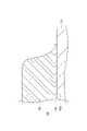
- FIG. 1 is a schematic diagram showing an example of a composite substrate.
- FIG. 2 is an enlarged cross-sectional view of the vicinity of the bonding surface of the composite substrate.
- FIG. 3 is an electron micrograph showing an example of a cross section of the composite substrate.
- FIG. 4 is an elemental distribution diagram showing the result of silver mapping analysis of the cross section of the composite substrate shown in FIG. 3 by an electron probe microanalyzer.
- FIG. 5 is an elemental distribution diagram showing the result of tin mapping analysis of the cross section of the composite substrate shown in FIG. 3 by an electron probe microanalyzer.
- FIG. 6 is an elemental distribution diagram showing the results of mapping analysis of titanium on the cross section of the composite substrate shown in FIG. 3 with an electron probe microanalyzer.
- each component in the composition means the total amount of the multiple substances present in the composition unless otherwise specified when there are multiple substances corresponding to each component in the composition. .
- An embodiment of the composite substrate includes a ceramic plate, a brazing layer containing silver and tin provided on the ceramic plate, and the brazing layer including a region formed by diffusing silver and tin. and a metal substrate bonded to the ceramic plate via the metal substrate.
- a ceramic plate and a metal base material are bonded via a brazing material layer, and active metal (titanium, etc.), which is a component of the brazing material layer, diffuses into the metal base material during bonding.
- active metal titanium, etc.
- a composite substrate may have one or more metal substrates.
- FIG. 1 is a schematic cross-sectional view showing an example of a composite substrate, showing a cross section of the composite substrate perpendicular to a bonding surface described later.
- a composite substrate 100 includes a ceramic plate 10 , a circuit board 40 and a heat sink 50 .
- the circuit board 40 is bonded to the surface 10A of the ceramics plate 10 at the bonding surface 40a, and has a structure in which the metal substrate 30 is bonded to the ceramics plate 10 via the brazing material layer 20.
- the heat sink 50 is joined to the back surface 10B of the ceramic plate 10 at the joining surface 50a, and has a structure in which the metal base 32 is joined to the ceramic plate 10 via the brazing material layer 22.
- two circuit boards 40 are bonded to the front surface 10A of the ceramic plate 10, and a radiator plate 50 is bonded to the back surface 10B of the ceramic plate 10. can be changed as appropriate.
- the circuit board 40 may have the function of transmitting electrical signals, while the heat sink 50 may have the function of transmitting heat. Note that the heat sink 50 may further have a function of transmitting electrical signals.
- the circuit board 40 and the heat sink 50 may be made of the same material or may be made of different materials. From the viewpoint of improving conductivity and heat dissipation, the metal substrates 30 and 32 may contain copper as a main component, for example. In this case, the circuit board 40 and the heat sink 50 may be composed of a brazing material layer and a copper plate.
- the above Y relative to the above X ratio is 0.10 to 1.00.
- the upper limit of the ratio may be, for example, 0.95 or less, 0.90 or less, or 0.85 or less.
- the fact that the upper limit of the above ratio is within the above range means that the excessive diffusion of the brazing material component is suppressed during the production of the composite substrate, and the heat cycle characteristics of the composite substrate 100 can be further improved.
- the lower limit of the above ratio may be, for example, 0.15 or more, 0.20 or more, or 0.25 or more.
- the bonding strength between the ceramic plate 10 and the metal substrates 30 and 32 can be further improved.
- the ratio may be adjusted within the ranges mentioned above, and may be, for example, 0.15-0.95, 0.20-0.90, or 0.25-0.85.
- the ratio of X to Z may be, for example, greater than 1.00, greater than 1.00 and 9.00 or less, or 5.00 to 9.00.
- X/Z value may be, for example, greater than 1.00, greater than 1.00 and 9.00 or less, or 5.00 to 9.00.
- the thickness of the silver-dispersed region may be, for example, 10-100 ⁇ m, 20-90 ⁇ m, or 30-80 ⁇ m.
- the thickness of the tin dispersed region may be, for example, 10-100 ⁇ m, 15-90 ⁇ m, or 20-80 ⁇ m.
- the thickness of the titanium dispersed regions may be, for example, 1-50 ⁇ m, 3-40 ⁇ m, or 5-30 ⁇ m.
- the dispersed region means a region in which a predetermined element is diffused, and includes parts of the brazing material layers 20, 22 and the metal substrates 30, 32.
- the boundary between the dispersed region and other regions is determined by elemental mapping analysis using an electron probe microanalyzer.
- the silver-dispersed region in the composite substrate 100 means the largest region in which a predetermined amount or more of silver is dispersed in the elemental distribution map obtained by the elemental mapping analysis. It is a region that sometimes includes a partial region of the metal substrate diffused from the brazing material.
- mapping data to be displayed is created, and the dispersion area and its thickness are determined. From the mapping data, it can be confirmed that each element diffuses perpendicularly from the joint surface 40 a toward the brazing material layer 20 and the metal substrate 30 . Then, in the mapping data, the diffusion distance is defined as the distance from the bonding surface 40a to the farthest position in the portion where the silver component diffuses.
- FIG. 2 shows an enlarged view of the joint surface 40a on the front surface 10A of the ceramic plate 10, the joint surface 50a on the back surface 10B of the ceramic plate 10 is similarly measured. The dispersed region is the joint surface (in the case of the composite substrate 100 in FIG.
- an electron beam microanalyzer for example, "JXA-8230" (trade name) manufactured by JEOL Ltd. can be used.
- the acceleration voltage: 15 kV, the irradiation current of 5 ⁇ 10 -8 A, and the measurement time: 30 msec/pixel are adopted, so that silver is dispersed in a predetermined amount or more. Identify the range.
- the ceramic plate 10 may be made of either silicon nitride or aluminum nitride, preferably containing silicon nitride.
- the ceramic plate may be, for example, an aluminum nitride sintered body or a silicon nitride sintered body.
- the brazing material layers 20 and 22 are layers obtained by heat-treating a brazing material.
- the brazing material contains silver and tin.
- the braze layers 20, 22 may contain active metals in addition to silver and tin.
- the active metal may be, for example, at least one selected from the group consisting of titanium (Ti), zirconium (Zr), hafnium (Hf), vanadium (V), niobium (Nb), and tantalum (Ta).
- the active metal content in the brazing filler metal may be adjusted based on the silver content being 100 parts by mass.
- the brazing material may contain metals such as copper (Cu) and indium (In) for the purpose of lowering the melting point.
- the brazing material layers 20 and 22 may contain, for example, carbon in addition to the active metal.
- the content of copper in the brazing material layers 20 and 22 is, for example, 17 parts by mass or less, 15 parts by mass or less, 14 parts by mass or less, 13 parts by mass or less, or 12 parts by mass with respect to 100 parts by mass of silver. It can be less than part.
- the content of copper in the brazing material layers 20 and 22 is, for example, 2 parts by mass or more, 4 parts by mass or more, 6 parts by mass or more, 8 parts by mass or more, or 10 parts by mass with respect to the silver content of 100 parts by mass. or more.
- the content of copper in the brazing material layers 20 and 22 may be adjusted within the range described above, and may be, for example, 2 to 17 parts by mass with respect to 100 parts by mass of silver.
- the brazing material layers 20, 22 contain tin. By containing tin, it is possible to reduce the influence of the heat treatment on the constituent members in the vicinity of the joint surface, so that the reliability of the obtained composite substrate can be further improved.
- the content of tin in the brazing material layers 20 and 22 is, for example, 6.0 parts by mass or less, 5.5 parts by mass or less, 5.0 parts by mass or less, or 3.0 parts by mass or less per 100 parts by mass of silver. It may be 0 parts by mass or less, or 1.0 parts by mass or less.
- the content of tin in the brazing material layers 20 and 22 is, for example, 0.5 parts by mass or more, 0.8 parts by mass or more, or 0.9 parts by mass or more with respect to 100 parts by mass of silver. you can
- the content of tin in the brazing material layers 20 and 22 may be adjusted within the above range, and may be, for example, 0.5 to 6.0 parts by mass with respect to 100 parts by mass of silver content.
- the upper limit of the content of titanium in the brazing material layer 20 is, for example, 7.0 parts by mass or less, 6.0 parts by mass or less, or 5.0 parts by mass or less, or It may be 4.0 parts by mass or less.
- the lower limit of the content of titanium in the brazing material layers 20 and 22 is, for example, 0.6 parts by mass or more, 0.8 parts by mass or more, or 1.0 parts by mass with respect to 100 parts by mass of silver content. or more.
- the content of titanium in the brazing material layers 20 and 22 may be adjusted within the above range, and may be, for example, 1.0 to 5.0 parts by mass with respect to 100 parts by mass of silver.
- the brazing material layers 20 and 22 may contain components other than metals, such as silver and active metals, as long as they do not impair the effects of the present invention. Impurities are also included in other components.
- the content of other components is, for example, 15.0% by mass or less, 12.0% by mass or less, 10.0% by mass or less, 5.0% by mass or less, or 3.0% by mass, based on the total amount of the brazing material layer. % by mass or less, 1.0% by mass or less, or 0.5% by mass or less.
- the upper limit of the thickness of the brazing material layers 20 and 22 may be, for example, 20 ⁇ m or less, 18 ⁇ m or less, or 15 ⁇ m or less. When the upper limit of the thickness is within the above range, the heat cycle characteristics can be made more sufficient, and even after use in a high heat dissipation environment, the brazing material layers 20 and 22 are not damaged by thermal stress. It is possible to more sufficiently suppress the occurrence of peeling and the like.
- the lower limit of the thickness of the brazing material layers 20 and 22 may be, for example, 3 ⁇ m or more, 5 ⁇ m or more, or 8 ⁇ m or more.
- the thickness of the brazing material layer may be adjusted within the above range, and may be, for example, 3-20 ⁇ m.
- the thickness of the brazing filler metal layer in this specification means a value measured in an electron microscope image of a cross section perpendicular to the joint surface between the ceramic plate and the metal substrate in the composite substrate.
- the thickness of the brazing filler metal layer is the joint surface (in the case of the composite substrate 100 in FIG.
- the ceramic plate 10 Two joint surfaces 40a on the front surface 10A of the ceramic plate 10 and a joint surface 50a on the back surface 10B of the ceramic plate 10), the maximum value of the thickness of the brazing material layer is measured, and the arithmetic average value is adopted. .
- the composite substrate 100 has excellent bonding strength between the ceramic plate 10 and the metal substrates 30 and 32.
- the bonding strength between the ceramic plate 10 and the metal substrates 30, 32 can be, for example, 80 N/cm or more, 100 N/cm or more, 120 N/cm or more, or 140 N/cm or more.
- Bonding strength means the value obtained by dividing the maximum peeling load (unit: N) when part of the metal substrate is peeled off at 90° (vertical direction) by the width of the metal substrate (unit: cm). . Specifically, the measurement is carried out by the method described in Examples below.
- the composite substrate 100 can exhibit excellent heat cycle characteristics.
- the heat cycle characteristics are measured according to the method described in JIS C 60068-2-14:2011 "Environmental test method-Electrical/electronics-Part 2-14: Temperature change test method (test symbol: N)". It can be evaluated by performing a change test.
- the composite substrate 100 described above can be manufactured, for example, by the following method.
- One embodiment of the method for manufacturing a composite substrate includes a step of forming a slurry containing an inorganic compound powder, a sintering aid, a binder resin, and a solvent to obtain a green sheet (green sheet preparation step), and heating the green sheet.
- a step of obtaining a ceramic plate by treatment (ceramic plate preparation step); a step of laminating a metal substrate onto the ceramic plate via a brazing filler metal containing silver and tin to obtain a laminate (lamination step); and a step of heat-treating the body to obtain a composite substrate (heat-treating step).
- a slurry containing the components that will be the raw materials for the ceramic plate is prepared and formed into a sheet to prepare the green sheet.
- the slurry molding method may be, for example, a doctor blade method, an extrusion molding method, or the like.
- Examples of inorganic compounds include silicon nitride (Si 3 N 4 ), aluminum nitride (AlN), silicon carbide, and aluminum oxide.
- Examples of sintering aids include metal oxides, fluorides, chlorides, nitrates, and sulfates of rare earth elements, and metal oxides, fluorides, chlorides, nitrates, and sulfates of alkaline earth metals. be done. These may be used alone or in combination of two or more.
- the sintering aid may include oxides of alkaline earth metals, such as magnesium oxide.
- binder resins examples include methyl cellulose, ethyl cellulose, polyvinyl alcohol, polyvinyl butyral, and (meth)acrylic resins.
- binder resins include methyl cellulose, ethyl cellulose, polyvinyl alcohol, polyvinyl butyral, and (meth)acrylic resins.
- solvents include organic solvents such as ethanol and toluene. The viscosity of the slurry can be easily adjusted by using the binder resin and solvent.
- the slurry may contain other components in addition to the inorganic compound powder, sintering aid, binder resin, and solvent.
- Other components include, for example, plasticizers and dispersants.
- plasticizers include purified glycerin, glycerin trioleate, diethylene glycol, phthalic acid plasticizers such as di-n-butyl phthalate, and dibasic acid plasticizers such as di-2-ethylhexyl sebacate.
- Dispersants include, for example, poly(meth)acrylates and (meth)acrylic acid-maleate copolymers.
- the ceramic plate preparation process is a process of heat-treating the green sheet obtained by molding to obtain a ceramic plate.
- the heat treatment of the green sheet is performed by a plurality of heat treatments, and includes, for example, a degreasing step in which heat treatment is performed at a heating temperature of 800 ° C. or less, and a sintering step in which heat treatment is performed at a higher temperature than the heating temperature in the degreasing step.
- You may In the degreasing process the green sheet is degreased mainly by burning the binder resin or the like. Then, in the sintering step, the raw material containing the inorganic compound and the sintering aid is sintered to obtain a ceramic plate.
- the heating temperature in the degreasing step may be, for example, 750-800°C, 760-790°C, or 780-790°C. By setting the upper limit of the heating temperature within the above range, the organic matter such as the binder resin is sufficiently removed before the inorganic compound is sintered, and the system is made more homogeneous. can be tied.
- the heating time in the degreasing step may be, for example, 0.5 to 20 hours.
- the heating temperature in the sintering process is higher than the heating temperature in the degreasing process.
- the heating temperature in the sintering step may be, for example, 1600-1950°C, 1700-1950°C, or 1800-1900°C.
- the heating time in the sintering step may be, for example, 5 to 15 hours.
- the sintering step may be performed under a non-oxidizing gas atmosphere such as nitrogen, argon, ammonia and hydrogen.
- the method for manufacturing a composite substrate according to the present embodiment has been described as a method including the step of preparing a ceramic plate, but instead of the green sheet preparation step and the ceramic plate preparation step, a ceramic plate prepared in advance (for example, a commercially available ceramic plate) may be used.
- a ceramic plate and a metal substrate are laminated using a brazing material containing silver and tin to obtain a laminate.
- a brazing material is applied to the surface of a ceramic plate to form a coating film, and a metal substrate is attached to the coating film.
- the metal base material is attached to both the front and back surfaces of the ceramic plate by the same operation.
- the shape of the metal substrate may be, for example, a flat plate shape.
- a circuit may be formed in advance on the metal substrate.
- a coating film containing brazing material can be provided by applying it to the surface of the ceramic plate by, for example, a roll coater method, screen printing method, transfer method, or the like.
- the brazing material is selected from the group consisting of, for example, titanium (Ti), zirconium (Zr), hafnium (Hf), vanadium (V), niobium (Nb), and tantalum (Ta), in addition to silver and tin. It may further contain at least one active metal.
- the active metal preferably comprises titanium.
- the active metal content in the brazing filler metal may be adjusted with the total amount of silver and copper being 100 parts by mass.
- the content of copper in the brazing filler metal is, for example, 16 parts by mass or less, 15 parts by mass or less, 14 parts by mass or less, 13 parts by mass or less, or 12 parts by mass or less per 100 parts by mass of silver. you can The content of copper in the brazing material is, for example, 2 parts by mass or more, 4 parts by mass or more, 6 parts by mass or more, 8 parts by mass or more, or 10 parts by mass or more per 100 parts by mass of silver. you can The content of copper in the brazing material may be adjusted within the above range, and may be, for example, 2 to 16 parts by mass with respect to 100 parts by mass of silver content.
- the brazing material contains tin.
- the content of tin in the brazing material is, for example, 6.0 parts by mass or less, 5.5 parts by mass or less, 5.0 parts by mass or less, or 3.0 parts by mass or less per 100 parts by mass of silver content. , or 1.0 parts by mass or less.
- the content of tin in the brazing material may be, for example, 0.5 parts by mass or more, 0.8 parts by mass or more, or 1 part by mass or more with respect to 100 parts by mass of silver.
- the content of tin in the brazing material may be adjusted within the above range, and may be, for example, 0.5 to 6.0 parts by mass with respect to 100 parts by mass of silver content.
- the upper limit of the content of titanium in the brazing material is, for example, 7.0 parts by mass or less, 6.0 parts by mass or less, 5.0 parts by mass or less, or 4.0 parts by mass or less per 100 parts by mass of silver content. It may be 0 parts by mass or less.
- the lower limit of the content of titanium in the brazing material may be, for example, 0.5 parts by mass or more, or 1.0 parts by mass or more with respect to 100 parts by mass of silver content.
- the content of titanium in the brazing material may be adjusted within the above range, and may be, for example, 1.0 to 5.0 parts by mass with respect to 100 parts by mass of silver content.
- the viscosity of the brazing filler metal at 25°C may be, for example, 5 to 40 Pa seconds.
- the viscosity of the brazing filler metal is within the above range, it is possible to form a more uniform coating film on the ceramic plate, and the melt viscosity during heat treatment for joining becomes appropriate, so that the ceramic plate and the metal substrate are bonded together. Since the brazing material can be spread sufficiently between the substrates, the bonding strength can be further improved, and the reliability of the composite substrate can be enhanced.
- the brazing material may contain, for example, an organic solvent and a binder in addition to metals such as silver and active metals.
- the content of the organic solvent in the brazing material may be, for example, 5-25% by mass.
- the binder content in the brazing material may be, for example, 2 to 15% by mass.
- the laminate is heated in a heating furnace to sufficiently bond the ceramic plate and the metal substrate to obtain a composite substrate.
- the heat treatment is performed by dividing the temperature pattern into a plurality of times.
- the heat treatment step includes, for example, a first heat treatment step of heat-treating the laminate at a temperature of less than 600 ° C., and a second heat treatment of heat-treating the laminate at a temperature higher than the heating temperature in the first heat treatment step. You may have a step.
- the upper limit of the heating temperature in the first heat treatment step may be, for example, less than 600°C, 590°C or less, 585°C or less, 500°C or less, 450°C or less, or 410°C or less.
- bondability can be further improved.
- the lower limit of the heating temperature in the first heat treatment step may be, for example, 350° C. or higher, 360° C. or higher, or 380° C. or higher.
- the heating temperature in the first heat treatment step may be adjusted within the above range, and may be, for example, 350°C or higher and lower than 600°C, or 400 to 410°C.
- the upper limit of the heating temperature in the second heat treatment step may be, for example, less than 850°C, 845°C or less, or 840°C or less. By setting the upper limit of the heating temperature within the above range, it is possible to suppress the diffusion of the components in the brazing filler metal into the metal substrate.
- the lower limit of the heating temperature in the first heat treatment step may be, for example, 770° C. or higher, 780° C. or higher, 790° C. or higher, or 800° C. or higher. By setting the lower limit of the heating temperature within the above range, it is possible to suppress defective bonding due to unmelted brazing material.
- the heating temperature in the second heat treatment step may be adjusted within the above range, and may be, for example, 770°C or higher and lower than 850°C, or 800 to 840°C.
- the heating time in the second heat treatment step is relatively short. By shortening the heating time, it is possible to suppress excessive diffusion of the components of the brazing filler metal among the ceramic plate, the brazing filler metal, and the metal substrate which are in a heated state. It can be made to contribute sufficiently to bonding.
- the heating time in the second heat treatment step may be, for example, 90 minutes or less, 80 minutes or less, or 70 minutes or less.
- the heating time in the second heat treatment step may be, for example, 5 minutes or longer, 10 minutes or longer, or 15 minutes or longer.
- the heating time in the second heat treatment step may be adjusted within the above range, and may be, for example, 5 to 90 minutes.
- the heating time in this specification means the time for maintaining the temperature after the temperature in the heating furnace reaches a predetermined temperature.
- the atmosphere in the furnace may be an inert gas such as nitrogen.
- the pressure inside the furnace may be, for example, a reduced pressure lower than the atmospheric pressure, or may be a vacuum.
- the first heat treatment step and the second heat treatment step may be performed while pressing the laminate in the stacking direction.
- the heating furnace may be of a continuous type that continuously manufactures a plurality of bonded bodies, or may be of a batch type that manufactures one or a plurality of bonded bodies.
- a circuit may be formed by removing part of the metal base material in the composite substrate. This step may be performed, for example, by etching or the like. Specifically, first, a photosensitive resist is printed on the surface of the composite substrate. Then, using an exposure device, a resist pattern having a predetermined shape is formed. The resist may be negative or positive. Uncured resist is removed, for example, by washing.
- the part of the metal substrate that is not covered with the resist pattern is removed by etching.
- the above operation can expose part of the front surface and/or the back surface of the ceramic plate. After that, by removing the resist pattern, a composite substrate having a circuit can be obtained.
- Table 1 shows the compositions of the brazing filler metals a to e used in the following examples and comparative examples.
- the numbers in Table 1 indicate parts by mass of each component.
- Example 1 [Production of composite substrate] A ceramic plate made of silicon nitride with a thickness of 0.32 mm, a first copper plate with a thickness of 0.3 mm, and a second copper plate with a thickness of 0.25 mm were prepared. Brazing material a was applied to predetermined locations on both sides of the ceramic plate.
- the first copper plate, the ceramic plate, and the second copper plate are laminated in this order via the brazing material a, and heat-treated in a heating furnace at 400°C for 120 minutes in a vacuum (first heat treatment step), and then the temperature was raised to 780° C., and heat treatment was performed at that temperature for 60 minutes (second heat treatment step).
- first heat treatment step the temperature was raised to 780° C.
- second heat treatment step the temperature was raised to 780° C.
- the first and second copper plates were joined to the ceramic plate.
- etching is performed using an aqueous solution of copper chloride and then a mixture of hydrogen peroxide and ammonium acid fluoride to cover the resist pattern. Removed the missing part. After that, the resist pattern was removed with an alkali stripper.
- Example 2 A composite substrate was produced in the same manner as in Example 1, except that the brazing material b was used as the brazing material and the heating temperature in the second heat treatment step was changed to 840°C.
- Example 3 A composite substrate was produced in the same manner as in Example 1, except that brazing material c was used as the brazing material and the heating time in the second heat treatment step was changed to 5 minutes.
- Example 4 A composite substrate was produced in the same manner as in Example 1, except that brazing material c was used as the brazing material, and the heating temperature in the second heat treatment step was changed to 840° C. and the heating time was changed to 90 minutes.
- Example 5 A composite substrate was produced in the same manner as in Example 1, except that the heating temperature in the second heat treatment step was changed to 800°C.
- Example 6 A composite substrate was produced in the same manner as in Example 1, except that the brazing material b was used as the brazing material and the heating temperature in the second heat treatment step was changed to 800°C.
- Example 1 A composite substrate was produced in the same manner as in Example 1 except that the brazing material d was used as the brazing material and the heating temperature in the second heat treatment step was changed to 840°C.
- Example 2 A composite substrate was produced in the same manner as in Example 1 except that the brazing material e was used as the brazing material and the heating temperature in the second heat treatment step was changed to 860°C.
- Example 3 A composite substrate was produced in the same manner as in Example 1, except that the heating temperature in the second heat treatment step was changed to 750°C.
- Example 4 A composite substrate was produced in the same manner as in Example 1, except that the heating temperature in the second heat treatment step was changed to 800° C. and the heating time was changed to 180 minutes.
- peeling Strength> For the composite substrates obtained in Examples and Comparative Examples, the peel strength was measured to evaluate the bonding strength. Specifically, the edge of a 5 mm wide pattern, which is part of the copper circuit pattern bonded to the composite substrate, was peeled off with pliers. The composite substrate was fixed to the table of a tensile tester, and the edge of the pattern was attached to the chuck of the pull tester. At this time, the surface of the ceramic plate was set so that the angle between the peeled copper circuit pattern and the surface of the ceramic plate was 90° (vertical direction).
- the peel strength is 100 N/cm or more.
- the copper plate and the brazing filler metal layer were peeled off using copper chloride solution and ammonium fluoride/hydrogen peroxide etching, and cracks on the surface of the ceramic plate were binarized (threshold value 140) using image analysis software GIMP2.
- the crack ratio was determined by calculating the crack area/circuit pattern area. The results are shown in Tables 2 and 3.
- C The crack rate is 5% or more.
Landscapes
- Chemical & Material Sciences (AREA)
- Engineering & Computer Science (AREA)
- Ceramic Engineering (AREA)
- Materials Engineering (AREA)
- Structural Engineering (AREA)
- Organic Chemistry (AREA)
- Ceramic Products (AREA)
- Manufacturing Of Printed Wiring (AREA)
Abstract
Description

[複合基板の作製]
厚さ0.32mmの窒化ケイ素製のセラミックス板、厚さ0.3mmの第一銅板、及び厚さ0.25mmの第二銅板を準備した。セラミックス板の両面の所定箇所にろう材aを塗布した。
ろう材としてろう材bを用い、第二の加熱処理工程における加熱温度を840℃に変更したこと以外は、実施例1と同様にして、複合基板を作製した。
ろう材としてろう材cを用い、第二の加熱処理工程における加熱時間を5分間に変更したこと以外は、実施例1と同様にして、複合基板を作製した。
ろう材としてろう材cを用い、第二の加熱処理工程における加熱温度を840℃に、加熱時間を90分間に変更したこと以外は、実施例1と同様にして、複合基板を作製した。
第二の加熱処理工程における加熱温度を800℃に変更したこと以外は、実施例1と同様にして、複合基板を作製した。
ろう材としてろう材bを用い、第二の加熱処理工程における加熱温度を800℃に変更したこと以外は、実施例1と同様にして、複合基板を作製した。
ろう材としてろう材dを用い、第二の加熱処理工程における加熱温度を840℃に変更したこと以外は、実施例1と同様にして、複合基板を作製した。
ろう材としてろう材eを用い、第二の加熱処理工程における加熱温度を860℃に変更したこと以外は、実施例1と同様にして、複合基板を作製した。
第二の加熱処理工程における加熱温度を750℃に変更したこと以外は、実施例1と同様にして、複合基板を作製した。
第二の加熱処理工程における加熱温度を800℃に、加熱時間を180分間に変更したこと以外は、実施例1と同様にして、複合基板を作製した。
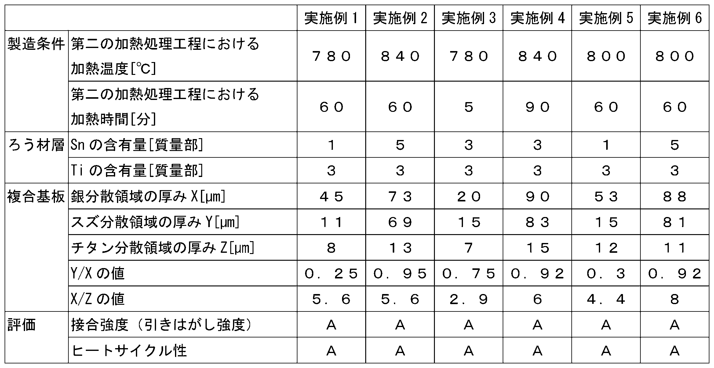
実施例1~6及び比較例1~4で作製した複合基板のそれぞれについて、電子線マイクロアナライザーによるマッピング分析によって特定される銀分散領域の厚み、スズ分散領域の厚み及びチタン分散領域の厚みを決定した。具体的には、任意で選択した接合面付近の銅板断面について接合面に水平方向に400μmの範囲をEPMAで観察した。400μmの範囲において各成分が拡散した部分のうち、最も離れた位置までの距離をろう材中成分の銅板への拡散距離とし、その平均値を採用した。結果を表2及び表3に示す。参考に実施例1で作製した複合基板についての評価結果を図3、図4、図5、及び図6に示す。
実施例及び比較例で得られた複合基板について、引きはがし強度を測定し、接合強度を評価した。具体的には、複合基板に接合された銅回路パターンの一部である幅5mmのパターンの端をペンチで引き剥がした。この複合基板を引張試験機の台に固定し、上記パターンの端をプル試験機のチャックに取り付けた。この時、セラミックス板の表面と引き剥がされた上記銅回路パターンの角度が90°(鉛直方向)になるように設置した。その後、引張試験機を作動させ、チャックを介して引き剥がされた上記パターンを上方に引っ張って移動させ、その時の最大引き剥がし荷重を測定した。その最大引き剥がし荷重を幅(0.5cm)で除して引きはがし強度を算出した。試験後、はく離面を目視で観察し、以下の基準で接合強度を評価した。結果を表2及び表3に示す。
A:引きはがし強度が100N/cm以上である。
B:引きはがし強度が80N/cm以上100N/cm未満である。
C:引きはがし強度が40N/cm以上80N/cm未満である。
D:引きはがし強度が40N/cm未満である。
実施例及び比較例で得られた複合基板について、JIS C 60068-2-14:2011「環境試験方法-電気・電子-第2―14部:温度変化試験方法(試験記号:N)」に記載の方法に準拠して、ヒートサイクル特性を評価した。具体的には、-40℃で15分間維持し、その後150℃で15分間維持することを1サイクルとして、2000回のヒートサイクル試験を行った。試験後、塩化銅液、及びフッ化アンモニウム/過酸化水素エッチングを用いて、銅板及びろう材層をはく離し、セラミックス板表面のクラックを画像解析ソフトGIMP2にて二値化(閾値140)し、上記クラックの面積を算出した後、クラック面積/回路パターンの面積の値を算出してクラック率を決定した。結果を表2及び表3に示す。
A:クラック率が1%未満である。
B:クラック率が1%以上5%未満である。
C:クラック率が5%以上である。

Claims (5)
- セラミックス板と、
銀及びスズを含有する、前記セラミックス板上に設けられたろう材層と、
銀及びスズが拡散して形成された領域を含む、前記ろう材層を介して前記セラミックス板と接合された金属基材と、を有し、
前記セラミックス板と前記金属基材との接合面に直交する断面における、銀分散領域の厚みをXとし、スズ分散領域の厚みをYとしたときに、前記Xに対する前記Yの比が0.10~1.00である、複合基板。 - 前記Xに対する前記Yの比が0.20~0.90である、請求項1に記載の複合基板。
- 前記ろう材層がチタンを更に含有し、前記セラミックス板と前記金属基材との接合面に直交する断面におけるチタン分散領域の厚みをZとしたときに、前記Zに対する前記Xの比が1.00超である、請求項1又は2に記載の複合基板。
- 前記セラミックス板が窒化ケイ素を含有する、請求項1~3のいずれか一項に記載の複合基板。
- 前記ろう材層の厚みが20μm以下である、請求項1~4のいずれか一項に記載の複合基板。
Priority Applications (3)
| Application Number | Priority Date | Filing Date | Title |
|---|---|---|---|
| CN202280021577.3A CN116997538A (zh) | 2021-03-24 | 2022-03-01 | 复合基板 |
| EP22774943.9A EP4310066A4 (en) | 2021-03-24 | 2022-03-01 | COMPOSITE SUBSTRATE |
| JP2022532877A JP7281603B2 (ja) | 2021-03-24 | 2022-03-01 | 複合基板 |
Applications Claiming Priority (2)
| Application Number | Priority Date | Filing Date | Title |
|---|---|---|---|
| JP2021-049938 | 2021-03-24 | ||
| JP2021049938 | 2021-03-24 |
Publications (1)
| Publication Number | Publication Date |
|---|---|
| WO2022202146A1 true WO2022202146A1 (ja) | 2022-09-29 |
Family
ID=83395561
Family Applications (1)
| Application Number | Title | Priority Date | Filing Date |
|---|---|---|---|
| PCT/JP2022/008566 Ceased WO2022202146A1 (ja) | 2021-03-24 | 2022-03-01 | 複合基板 |
Country Status (4)
| Country | Link |
|---|---|
| EP (1) | EP4310066A4 (ja) |
| JP (1) | JP7281603B2 (ja) |
| CN (1) | CN116997538A (ja) |
| WO (1) | WO2022202146A1 (ja) |
Cited By (1)
| Publication number | Priority date | Publication date | Assignee | Title |
|---|---|---|---|---|
| JP2025084029A (ja) * | 2023-11-21 | 2025-06-02 | 同欣電子工業股▲ふん▼有限公司 | 活性金属ろう付け基板及びその製造方法 |
Families Citing this family (1)
| Publication number | Priority date | Publication date | Assignee | Title |
|---|---|---|---|---|
| CN117655330A (zh) * | 2023-11-15 | 2024-03-08 | 江苏灿勤科技股份有限公司 | 一种铜基碳化硅复合陶瓷的制作方法 |
Citations (7)
| Publication number | Priority date | Publication date | Assignee | Title |
|---|---|---|---|---|
| JPH0524943A (ja) * | 1991-07-22 | 1993-02-02 | Ngk Insulators Ltd | 活性金属ろう材および活性金属ろう材を用いた金属部材とセラミツクス部材との接合方法 |
| JPH11130555A (ja) * | 1997-10-28 | 1999-05-18 | Kyocera Corp | セラミックス−銅接合用ろう材 |
| JP2003188310A (ja) * | 2001-12-18 | 2003-07-04 | Denki Kagaku Kogyo Kk | 電極端子付き回路基板の製造方法 |
| JP2014118310A (ja) | 2012-12-14 | 2014-06-30 | Denki Kagaku Kogyo Kk | セラミックス回路基板 |
| JP2016169111A (ja) * | 2015-03-11 | 2016-09-23 | デンカ株式会社 | セラミックス回路基板 |
| WO2018180965A1 (ja) * | 2017-03-30 | 2018-10-04 | 株式会社 東芝 | セラミックス銅回路基板およびそれを用いた半導体装置 |
| WO2022024990A1 (ja) * | 2020-07-27 | 2022-02-03 | 株式会社 東芝 | 接合体、回路基板、半導体装置、及び接合体の製造方法 |
Family Cites Families (3)
| Publication number | Priority date | Publication date | Assignee | Title |
|---|---|---|---|---|
| CN105452194B (zh) * | 2013-08-08 | 2017-05-03 | 株式会社东芝 | 电路基板以及半导体装置 |
| JP7144405B2 (ja) * | 2017-04-25 | 2022-09-29 | デンカ株式会社 | セラミックス回路基板及びその製造方法とそれを用いたモジュール |
| US11570890B2 (en) * | 2017-05-30 | 2023-01-31 | Denka Company Limited | Ceramic circuit board and module using same |
-
2022
- 2022-03-01 WO PCT/JP2022/008566 patent/WO2022202146A1/ja not_active Ceased
- 2022-03-01 EP EP22774943.9A patent/EP4310066A4/en not_active Withdrawn
- 2022-03-01 CN CN202280021577.3A patent/CN116997538A/zh active Pending
- 2022-03-01 JP JP2022532877A patent/JP7281603B2/ja active Active
Patent Citations (7)
| Publication number | Priority date | Publication date | Assignee | Title |
|---|---|---|---|---|
| JPH0524943A (ja) * | 1991-07-22 | 1993-02-02 | Ngk Insulators Ltd | 活性金属ろう材および活性金属ろう材を用いた金属部材とセラミツクス部材との接合方法 |
| JPH11130555A (ja) * | 1997-10-28 | 1999-05-18 | Kyocera Corp | セラミックス−銅接合用ろう材 |
| JP2003188310A (ja) * | 2001-12-18 | 2003-07-04 | Denki Kagaku Kogyo Kk | 電極端子付き回路基板の製造方法 |
| JP2014118310A (ja) | 2012-12-14 | 2014-06-30 | Denki Kagaku Kogyo Kk | セラミックス回路基板 |
| JP2016169111A (ja) * | 2015-03-11 | 2016-09-23 | デンカ株式会社 | セラミックス回路基板 |
| WO2018180965A1 (ja) * | 2017-03-30 | 2018-10-04 | 株式会社 東芝 | セラミックス銅回路基板およびそれを用いた半導体装置 |
| WO2022024990A1 (ja) * | 2020-07-27 | 2022-02-03 | 株式会社 東芝 | 接合体、回路基板、半導体装置、及び接合体の製造方法 |
Non-Patent Citations (1)
| Title |
|---|
| See also references of EP4310066A4 |
Cited By (2)
| Publication number | Priority date | Publication date | Assignee | Title |
|---|---|---|---|---|
| JP2025084029A (ja) * | 2023-11-21 | 2025-06-02 | 同欣電子工業股▲ふん▼有限公司 | 活性金属ろう付け基板及びその製造方法 |
| JP7705503B2 (ja) | 2023-11-21 | 2025-07-09 | 同欣電子工業股▲ふん▼有限公司 | 活性金属ろう付け基板及びその製造方法 |
Also Published As
| Publication number | Publication date |
|---|---|
| JP7281603B2 (ja) | 2023-05-25 |
| EP4310066A1 (en) | 2024-01-24 |
| EP4310066A4 (en) | 2024-10-02 |
| CN116997538A (zh) | 2023-11-03 |
| JPWO2022202146A1 (ja) | 2022-09-29 |
Similar Documents
| Publication | Publication Date | Title |
|---|---|---|
| US11570890B2 (en) | Ceramic circuit board and module using same | |
| EP4079712B1 (en) | Circuit board, joined body, and methods for producing same | |
| JP7212700B2 (ja) | セラミックス-銅複合体、セラミックス回路基板、パワーモジュール及びセラミックス-銅複合体の製造方法 | |
| JP6742073B2 (ja) | セラミックス回路基板 | |
| JP7281603B2 (ja) | 複合基板 | |
| JP2025027018A (ja) | セラミックススクライブ基板、セラミックス基板、セラミックススクライブ基板の製造方法、セラミックス基板の製造方法、セラミックス回路基板の製造方法、及び、半導体素子の製造方法 | |
| JP2013211545A (ja) | セラミックス回路基板及びその製造方法、半導体モジュール | |
| JP7330382B2 (ja) | 複合基板 | |
| JP3933287B2 (ja) | ヒートシンク付き回路基板 | |
| JP4819516B2 (ja) | 導電性ペースト及びその導電性ペーストを用いたセラミック多層回路基板 | |
| EP4456676A1 (en) | Ceramic scribe circuit substrate, ceramic circuit substrate, method for manufacturing ceramic scribe circuit substrate, method for manufacturing ceramic circuit substrate, and method for manufacturing semiconductor device | |
| JP3454331B2 (ja) | 回路基板及びその製造方法 | |
| JP7441234B2 (ja) | 回路基板及びこれを備えるモジュール | |
| JP2002314220A (ja) | 回路基板の製造方法 | |
| JP3560357B2 (ja) | 窒化アルミニウム焼結体の製造方法 | |
| JP7708622B2 (ja) | セラミック複合基板 | |
| JP2025141619A (ja) | 金属-セラミックス接合基板の製造方法 | |
| JP2018030738A (ja) | セラミックス基板とアルミニウム含浸炭化珪素多孔質体との接合体の製造方法 | |
| CN1665377A (zh) | 陶瓷多层基板的制造方法 | |
| WO2023100917A1 (ja) | 接合用金属ペースト、および、接合体の製造方法、絶縁回路基板の製造方法 | |
| WO2023188670A1 (ja) | 回路基板及びその製造方法 | |
| JPH11354698A (ja) | ヒートシンク付き回路基板 | |
| JP2004200338A (ja) | セラミック多層積層体の製造方法 | |
| JPH1197807A (ja) | 回路基板 |
Legal Events
| Date | Code | Title | Description |
|---|---|---|---|
| ENP | Entry into the national phase |
Ref document number: 2022532877 Country of ref document: JP Kind code of ref document: A |
|
| 121 | Ep: the epo has been informed by wipo that ep was designated in this application |
Ref document number: 22774943 Country of ref document: EP Kind code of ref document: A1 |
|
| WWE | Wipo information: entry into national phase |
Ref document number: 202280021577.3 Country of ref document: CN |
|
| WWE | Wipo information: entry into national phase |
Ref document number: 2022774943 Country of ref document: EP |
|
| NENP | Non-entry into the national phase |
Ref country code: DE |
|
| ENP | Entry into the national phase |
Ref document number: 2022774943 Country of ref document: EP Effective date: 20231018 |
|
| WWW | Wipo information: withdrawn in national office |
Ref document number: 2022774943 Country of ref document: EP |