WO2022202573A1 - 装置及び方法 - Google Patents
装置及び方法 Download PDFInfo
- Publication number
- WO2022202573A1 WO2022202573A1 PCT/JP2022/012078 JP2022012078W WO2022202573A1 WO 2022202573 A1 WO2022202573 A1 WO 2022202573A1 JP 2022012078 W JP2022012078 W JP 2022012078W WO 2022202573 A1 WO2022202573 A1 WO 2022202573A1
- Authority
- WO
- WIPO (PCT)
- Prior art keywords
- information
- network
- rrc
- user equipment
- base station
- Prior art date
- Legal status (The legal status is an assumption and is not a legal conclusion. Google has not performed a legal analysis and makes no representation as to the accuracy of the status listed.)
- Ceased
Links
Images



Classifications
-
- H—ELECTRICITY
- H04—ELECTRIC COMMUNICATION TECHNIQUE
- H04W—WIRELESS COMMUNICATION NETWORKS
- H04W76/00—Connection management
- H04W76/20—Manipulation of established connections
- H04W76/27—Transitions between radio resource control [RRC] states
-
- H—ELECTRICITY
- H04—ELECTRIC COMMUNICATION TECHNIQUE
- H04W—WIRELESS COMMUNICATION NETWORKS
- H04W48/00—Access restriction; Network selection; Access point selection
- H04W48/18—Selecting a network or a communication service
-
- H—ELECTRICITY
- H04—ELECTRIC COMMUNICATION TECHNIQUE
- H04W—WIRELESS COMMUNICATION NETWORKS
- H04W68/00—User notification, e.g. alerting and paging, for incoming communication, change of service or the like
- H04W68/12—Inter-network notification
-
- H—ELECTRICITY
- H04—ELECTRIC COMMUNICATION TECHNIQUE
- H04W—WIRELESS COMMUNICATION NETWORKS
- H04W36/00—Hand-off or reselection arrangements
- H04W36/14—Reselecting a network or an air interface
- H04W36/142—Reselecting a network or an air interface over the same radio air interface technology
Definitions
- the present disclosure relates to devices and methods.
- Non-Patent Document 1 even if user equipment (UE) is in an RRC (Radio Resource Control) connection state in network A, by setting a gap in communication in network A, the UE Techniques for monitoring paging in B are being considered. This technique is called short-time switching.
- RRC Radio Resource Control
- Non-Patent Document 1 a technique is being studied in which the UE notifies network A that it will temporarily withdraw from network A when there is an incoming call with high priority in network B. This may suppress RRC state mismatch between network A and the UE. This technique is called long-time switching.
- Non-Patent Document 2 describes pre-configuring, via RRC signaling, the RRC state to which the UE should transition when leaving for a leave notification without a network response. Also, in Non-Patent Document 3, during a suspension (i.e., leaving), the UE ASSISTANCE INFORMATION message is used to indicate the cause of the suspension (i.e., leaving) and the preferred RRC state (e.g., RRC idle or RRC Sending information such as inactive to the network is described.
- the preferred RRC state e.g., RRC idle or RRC Sending information such as inactive to the network is described.
- Non-Patent Document 2 describes configuring in advance the RRC state to which the UE should transition when leaving, but does not show a specific method for reliably realizing it without unnecessary signaling. The inventor has found the problem. Furthermore, according to Non-Patent Document 3, when switching networks, the UE transmits information on the preferred RRC state to the network, confirms reception of the information in the network, and then performs the switching. Therefore, the inventor found a problem that network switching may take a long time.
- An object of the present disclosure is to provide a user equipment, a base station and a method that enable the user equipment to reliably switch mobile networks quickly without unnecessary signaling.
- a device receives second information configuring the device to transmit a UE Assistance Information message including first information indicating an RRC state of RRC idle or RRC inactive and the communication processing unit, based on the second information, before switching from the first network to the second network by the device that is in an RRC connection state in the first network. Sending a UE Assistance Information message containing the first information to the first network.
- a device in a first network configures a user equipment to send a UE Assistance Information message including first information indicating an RRC state of RRC idle or RRC inactive. to the user equipment, wherein the communication processing unit is configured to, before switching from the first network to the second network by the user equipment that is in an RRC connected state in the first network, receiving from the user equipment a UE Assistance Information message transmitted based on the second information, the UE Assistance Information message including the first information;
- a method performed by a device includes: second information configuring the device to send a UE Assistance Information message including first information indicating an RRC state of RRC idle or RRC inactive. receiving and transmitting said first information based on said second information prior to switching from said first network to a second network by said device in an RRC connected state in a first network; and sending a UE Assistance Information message to the first network.
- a method performed by a device in a first network configures a user equipment to transmit a UE Assistance Information message including first information indicating an RRC state of RRC idle or RRC inactive. transmitting second information to the user equipment; and transmitting the second information prior to switching from the first network to a second network by the user equipment being in RRC connection state in the first network. receiving, from the user equipment, a UE Assistance Information message sent based on said first information, said UE Assistance Information message comprising said first information.
- the present disclosure it is possible to reliably realize rapid switching of mobile networks by user equipment without unnecessary signaling. It should be noted that the present disclosure may provide other effects instead of or in addition to the above effects.
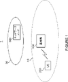
- FIG. 1 is an explanatory diagram showing an example of a schematic configuration of a system according to an embodiment of the present disclosure
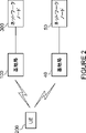
- FIG. FIG. 4 is an explanatory diagram for explaining an example of a case in which a user device according to an embodiment of the present disclosure is equipped with two SIM cards
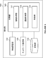
- 2 is a block diagram showing an example of a schematic functional configuration of a base station according to an embodiment of the present disclosure
- FIG. 2 is a block diagram showing an example of a schematic hardware configuration of a base station according to an embodiment of the present disclosure
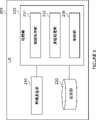
- FIG. 2 is a block diagram showing an example of a schematic functional configuration of a user device according to an embodiment of the present disclosure
- FIG. 2 is a block diagram showing an example of a schematic hardware configuration of a user device according to an embodiment of the present disclosure
- FIG. FIG. 4 is a sequence diagram for explaining an example of a schematic flow of processing according to an embodiment of the present disclosure
- FIG. 11 is a sequence diagram for explaining an example of a schematic flow of processing according to the first modification of
- system 1 includes base station 100 , user equipment (UE) 200 and core network 30 .
- Core network 30 includes network nodes 300 .
- system 1 is a system that complies with the Technical Specifications (TS) of 3GPP (Third Generation Partnership Project). More specifically, for example, the system 1 is a system conforming to 5G or NR (New Radio) TS. Naturally, the system 1 is not limited to this example.
- TS Technical Specifications
- 3GPP Third Generation Partnership Project
- NR New Radio
- Base station 100 The base station 100 is a node of a radio access network (RAN) and communicates with UEs (eg, UE 200) located within the coverage area 10 of the base station 100.
- RAN radio access network
- the base station 100 communicates with the UE (for example, the UE 200) using the RAN protocol stack.
- the protocol stack includes RRC (Radio Resource Control), SDAP (Service Data Adaptation Protocol), PDCP (Packet Data Convergence Protocol), RLC (Radio Link Control), MAC (Medium Access Control), and Physical: PHY) layer protocol.
- the protocol stack may not include all of these protocols, but some of these protocols.
- the base station 100 is a gNB.
- a gNB is a node that provides NR user plane and control plane protocol terminations towards the UE and is connected to the 5GC (5G Core Network) via the NG interface.
- base station 100 may be an en-gNB.
- An en-gNB is a node that provides NR user plane and control plane protocol termination for UEs and acts as a secondary node in EN-DC (E-UTRA-NR Dual Connectivity).
- the base station 100 may include multiple nodes.
- the plurality of nodes may include a first node that hosts a higher layer included in the protocol stack and a second node that hosts a lower layer included in the protocol stack. good.
- the upper layers may include RRC, SDAP and PDCP, and the lower layers may include RLC, MAC and PHY layers.
- the first node may be a CU (central unit), and the second node may be a DU (Distributed Unit).
- the plurality of nodes may include a third node that performs lower-level processing of the PHY layer, and the second node may perform higher-level processing of the PHY layer.
- the third node may be an RU (Radio Unit).
- the base station 100 may be one of the plurality of nodes, or may be connected to another unit among the plurality of nodes.
- the base station 100 may be an IAB (Integrated Access and Backhaul) donor or an IAB node.
- IAB Integrated Access and Backhaul
- UE200 UE 200 communicates with a base station.
- UE 200 communicates with base station 100 when located within coverage area 10 of base station 100 .
- UE 200 communicates with a base station (eg, base station 100) using the above protocol stack.
- a base station eg, base station 100
- the UE 200 can be equipped with two or more SIM cards. That is, the UE 200 is a multi-SIM UE or multi-SIM device.
- the UE 200 can communicate in two or more mobile networks respectively corresponding to the two or more SIM cards.
- a mobile network may simply be called a network.
- the UE 200 is a mobile network corresponding to one of the two or more SIM cards, and includes the base station 100 and the network node 300 (hereinafter referred to as "first mobile network”). ). Furthermore, the UE 200 can communicate in a mobile network (hereinafter referred to as "second mobile network”) corresponding to the other one of the two or more SIM cards.
- first mobile network the base station 100 and the network node 300
- second mobile network a mobile network corresponding to the other one of the two or more SIM cards.
- UE 200 can communicate in a first mobile network including base station 100 and network node 300 and a second mobile network including base station 40 and network node 50.
- the UE 200 may be in RRC connected state in said first mobile network and in RRC idle state or RRC inactive state in said second mobile network.
- UE 200 may receive paging messages sent by base station 40 in the second mobile network while communicating with base station 100 in the first mobile network.
- Network node 300 is a network function of core network 30 .
- the network node 300 is an AMF (Access and Mobility Management Function).
- the base station 100 includes a wireless communication unit 110, a network communication unit 120, a storage unit 130 and a processing unit 140.
- FIG. 1 An example of the functional configuration of the base station 100 according to the embodiment of the present disclosure will be described with reference to FIG. Referring to FIG. 3, the base station 100 includes a wireless communication unit 110, a network communication unit 120, a storage unit 130 and a processing unit 140.
- FIG. 1 An example of the functional configuration of the base station 100 according to the embodiment of the present disclosure will be described with reference to FIG.
- the base station 100 includes a wireless communication unit 110, a network communication unit 120, a storage unit 130 and a processing unit 140.
- the wireless communication unit 110 wirelessly transmits and receives signals.
- the radio communication unit 110 receives signals from UEs and transmits signals to the UEs.
- the network communication unit 120 receives signals from the network and transmits signals to the network.
- the storage unit 130 stores various information.
- the processing unit 140 provides various functions of the base station 100.
- the processing unit 140 includes an information acquisition unit 141 , a communication processing unit 143 and a control unit 145 .
- the processing unit 140 may further include components other than these components. That is, the processing unit 140 can perform operations other than those of these components. Specific operations of the information acquisition unit 141, the communication processing unit 143, and the control unit 145 will be described in detail later.
- the processing unit 140 communicates with the UE (eg, UE 200) via the wireless communication unit 110.
- the processing unit 140 communicates with other nodes (for example, the network node 300 in the core network 30 or other base stations) via the network communication unit 120 .
- base station 100 comprises antenna 181 , RF circuitry 183 , network interface 185 , processor 187 , memory 189 and storage 191 .
- Antenna 181 converts a signal into radio waves and radiates the radio waves into space. Also, the antenna 181 receives radio waves in space and converts the radio waves into signals.
- Antenna 181 may include a transmit antenna and a receive antenna, or may be a single antenna for transmission and reception.
- Antenna 181 may be a directional antenna and may include multiple antenna elements.
- the RF circuit 183 performs analog processing of signals transmitted and received via the antenna 181 .
- RF circuitry 183 may include high frequency filters, amplifiers, modulators, low pass filters, and the like.
- the network interface 185 is, for example, a network adapter, which transmits signals to and receives signals from the network.
- the processor 187 performs digital processing of signals transmitted and received via the antenna 181 and the RF circuit 183.
- the digital processing includes processing of the protocol stack of the RAN.
- Processor 187 also processes signals sent and received via network interface 185 .
- Processor 187 may include multiple processors or may be a single processor.
- the multiple processors may include a baseband processor that performs the digital processing and one or more processors that perform other processing.
- the memory 189 stores programs executed by the processor 187, parameters related to the programs, and various other information.
- the memory 189 may include at least one of ROM (Read Only Memory), EPROM (Erasable Programmable Read Only Memory), EEPROM (Electrically Erasable Programmable Read Only Memory), RAM (Random Access Memory), and flash memory. All or part of memory 189 may be included within processor 187 .
- the storage 191 stores various information.
- the storage 191 may include at least one of SSD (Solid State Drive) and HDD (Hard Disc Drive).
- the wireless communication unit 110 may be implemented by an antenna 181 and an RF circuit 183.
- Network communication unit 120 may be implemented by network interface 185 .
- Storage unit 130 may be implemented by storage 191 .
- Processing unit 140 may be implemented by processor 187 and memory 189
- Part or all of the processing unit 140 may be virtualized. In other words, part or all of the processing unit 140 may be implemented as a virtual machine. In this case, part or all of the processing unit 140 may operate as a virtual machine on a physical machine (that is, hardware) including a processor, memory, etc. and a hypervisor.
- the base station 100 may include a memory (ie, memory 189) for storing programs and one or more processors (ie, processor 187) capable of executing the programs.
- the one or more processors may execute the program to perform the operation of the processing unit 140 .
- the program may be a program for causing the processor to execute the operation of the processing unit 140 .
- FIG. 5 An example configuration of the UE 200 according to the embodiment of the present disclosure will be described with reference to FIGS. 5 and 6.
- FIG. 5 An example configuration of the UE 200 according to the embodiment of the present disclosure will be described with reference to FIGS. 5 and 6.
- FIG. 5 An example configuration of the UE 200 according to the embodiment of the present disclosure will be described with reference to FIGS. 5 and 6.
- FIG. 5 An example configuration of the UE 200 according to the embodiment of the present disclosure will be described with reference to FIGS. 5 and 6.
- the UE 200 includes a wireless communication section 210, a storage section 220 and a processing section 230.
- FIG. 5 An example of the functional configuration of the UE 200 according to the embodiment of the present disclosure will be described with reference to FIG. Referring to FIG. 5, the UE 200 includes a wireless communication section 210, a storage section 220 and a processing section 230.
- FIG. 5 An example of the functional configuration of the UE 200 according to the embodiment of the present disclosure will be described with reference to FIG. Referring to FIG. 5, the UE 200 includes a wireless communication section 210, a storage section 220 and a processing section 230.
- the wireless communication unit 210 wirelessly transmits and receives signals.
- the wireless communication unit 210 receives signals from base stations and transmits signals to the base stations.
- the radio communication unit 210 receives signals from other UEs and transmits signals to other UEs.
- the storage unit 220 stores various information.
- the processing unit 230 provides various functions of the UE 200.
- the processing unit 230 includes an information acquisition unit 231 , a communication processing unit 233 and a control unit 235 .
- the processing unit 230 may further include other components other than these components. That is, the processing unit 230 can perform operations other than those of these components. Specific operations of the information acquisition unit 231, communication processing unit 233, and control unit 235 will be described in detail later.
- the processing unit 230 communicates with a base station (for example, the base station 100 or the base station 40) or another UE via the wireless communication unit 210.
- a base station for example, the base station 100 or the base station 40
- another UE via the wireless communication unit 210.
- UE 200 comprises antenna 281 , RF circuitry 283 , processor 285 , memory 287 and storage 289 .
- the antenna 281 converts the signal into radio waves and radiates the radio waves into space. Also, the antenna 281 receives radio waves in space and converts the radio waves into signals.
- Antenna 281 may include a transmit antenna and a receive antenna, or may be a single antenna for transmission and reception. Antenna 281 may be a directional antenna and may include multiple antenna elements.
- the RF circuit 283 performs analog processing of signals transmitted and received via the antenna 281 .
- RF circuitry 283 may include high frequency filters, amplifiers, modulators, low pass filters, and the like.
- the processor 285 performs digital processing of signals transmitted and received via the antenna 281 and the RF circuit 283.
- the digital processing includes processing of the protocol stack of the RAN.
- Processor 285 may include multiple processors or may be a single processor.
- the multiple processors may include a baseband processor that performs the digital processing and one or more processors that perform other processing.
- the memory 287 stores programs executed by the processor 285, parameters related to the programs, and various other information.
- Memory 287 may include at least one of ROM, EPROM, EEPROM, RAM, and flash memory. All or part of memory 287 may be included within processor 285 .
- the storage 289 stores various information.
- Storage 289 may include at least one of SSD and HDD.
- the wireless communication unit 210 may be implemented by an antenna 281 and an RF circuit 283.
- Storage unit 220 may be implemented by storage 289 .
- Processing unit 230 may be implemented by processor 285 and memory 287 .
- the processing unit 230 may be implemented by an SoC (System on Chip) including a processor 285 and a memory 287.
- SoC System on Chip
- the SoC may include RF circuitry 283 and the wireless communication unit 210 may also be implemented by the SoC.
- the UE 200 may include a memory that stores a program (ie, memory 287) and one or more processors that can execute the program (ie, processor 285).
- One or more processors may execute the programs described above to perform the operations of the processing unit 230 .
- the program may be a program for causing the processor to execute the operation of the processing unit 230 .
- UE 200 (information acquisition unit 231) acquires state transition information indicating the RRC state to which UE 200 transitions when switching from the first mobile network to the second mobile network.
- UE 200 (communication processing unit 233) transmits a UE Assistance Information message including the state transition information to base station 100 of the first mobile network in response to registration of UE 200 in the second mobile network.
- the base station 100 receives from the UE 200 the UE Assistance Information message including the state transition information.
- the base station 100 (information acquisition unit 141) acquires the state transition information.
- the RRC state indicated by the state transition information is set as the RRC state of UE 200 after the switching in each of base station 100 and UE 200 .
- the RRC state is RRC idle state or RRC inactive state.
- the RRC state is the RRC state to which the UE 200 transitions when switching. Since UE 200 voluntarily releases the RRC connection at the time of switching, the above RRC state can also be said to be an RRC state in which UE 200 transitions according to UE 200's voluntary release of the RRC connection.
- the base station 100 acquires configuration information for configuring the UE 200 to transmit the state transition information.
- the base station 100 (communication processing unit 143) transmits an RRC Reconfiguration message including the configuration information to the UE200.
- the base station 100 transmits the configuration information to the UE 200 because the UE 200 has multi-SIM capability.
- the UE 200 receives the RRC Reconfiguration message including the configuration information from the base station 100.
- the UE 200 (information acquisition unit 231) acquires the configuration information.
- the UE 200 (communication processing unit 233) transmits the state transition information to the base station 100 on condition that the configuration information is received.
- UE 200 (communication processing unit 233) transmits the UE Assistance Information message including the state transition information to base station 100 in response to registration of UE 200 in the second mobile network. More specifically, UE 200 (communication processing unit 233) transmits the UE Assistance Information message to base station 100 upon completion of the registration.
- the UE 200 (communication processing unit 233) performs the registration when attaching to the second mobile network or performing location registration in the second mobile network.
- UE 200 (communication processing unit 233) transmits a REGISTRATION REQUEST message to network node 50 via base station 40 as a procedure for registration in the second mobile network, and transmits a REGISTRATION ACCEPT message to base station 40. from network node 50 via .
- the REGISTRATION REQUEST message and the REGISTRATION ACCEPT message are NAS (Non-Access Stratum) messages.
- the state transition information is transmitted and received. This makes it possible, for example, to reliably realize prompt switching to the second mobile network by the UE 200 without unnecessary signaling. More specifically, since the state transition information becomes necessary in the base station 100 after the registration in the second mobile network, the state transition information is transmitted only when necessary. That is, the state transition information is not sent unnecessarily, thus avoiding wasteful signaling. Further, since the state transition information is transmitted to the base station 100 in response to the registration in the second mobile network, the base station 100, before paging to the UE 200 in the second mobile network, The above state transition information can be acquired. Therefore, the UE 200 can reliably perform prompt switching to the second mobile network. Also, by using the UE ASSISTANCE INFORMATION message, the UE 200 can voluntarily transmit the state transition information to the base station 100 in response to the registration in the second mobile network.
- the UE 200 (communication processing unit 233) transmits a message for notification of switching to the first mobile network.
- the message is an RRC message for notifying the handover.
- UE 200 (communication processing unit 233 ) transmits the message to base station 100 .
- the base station 100 (communication processing unit 143) receives the message from the UE200.
- UE200 (control unit 235), in response to receiving an acknowledgment (Acknowledge: ACK) corresponding to the message for notification of the switching, UE200 the RRC state (for example, RRC idle or RRC inactive).
- the ACK may be an ACK of the RLC layer, which is a layer 2 protocol, or an ACK of HARQ (hybrid automatic repeat request) of the MAC layer, which is a layer 2 protocol. This allows, for example, minimal acknowledgment of the message and rapid switching.
- the base station 100 transitions the UE 200 to the RRC state in the base station 100 in response to the reception of the message. That is, the RRC state of UE 200 maintained in base station 100 becomes the RRC state indicated by the state transition information.
- Such switching enables the UE 200 to perform communication in the second mobile network even if it is in the RRC connection state in the first mobile network. Also, the state transition information can suppress RRC state inconsistency between the first network (especially the base station 100) and the UE 200.
- An RRC Reconfiguration procedure is performed between the UE 200 and the base station 100 (S401). For example, base station 100 transmits to UE 200 an RRC Reconfiguration message including configuration information for configuring UE 200 to transmit state transition information.
- the UE 200 performs procedures for registration in the second mobile network (S403).
- the UE 200 transmits to the base station 100 a UE Assistance Information message including state transition information indicating the RRC state to which the UE 200 transitions when switching from the first mobile network to the second mobile network. (S405).
- the base station 100 receives the UE Assistance Information message and acquires the state transition information.
- UE 200 and base station 100 set the above RRC state as the RRC state of UE 200 after network switching (S407).
- the RRC state is RRC inactive.
- the UE 200 receives the paging message from the base station 40 (S409).
- the paging message includes identification information of UE 200 and corresponding priority information. For example, the information indicates high priority.
- the UE 200 determines switching from the first mobile network to the second mobile network (S411). For example, the UE 200 determines to perform the switching.
- the UE 200 transmits a message for notification of switching to the base station 100 (S413).
- the message is an RRC message for long term switching.
- the UE 200 receives an ACK (eg, RLC ACK or HARQ ACK) corresponding to the above message (S415), and transitions to the above RRC state (eg, RRC inactive) (S417).
- ACK eg, RLC ACK or HARQ ACK
- RRC state eg, RRC inactive
- the UE 200 transmits a paging response to the base station 40 (S419). After that, the UE 200 starts communication in the second mobile network (S421).
- base station 100 Upon receiving the message from UE 200 (S413), base station 100 notifies network node 300 of the switching (S423), and network node 300 stops data transmission and reception with UE 200 (S425).
- the base station 100 transmits a response to the message to the UE 200 (S427), and causes the UE 200 to transition to RRC inactive in the base station 100 (S429).
- steps S417-S421 and the processing of steps S423-S429 may be performed in parallel.
- the UE 200 performs Sending a message to the first mobile network.
- the message is an RRC message for notifying the switching.
- the above messages according to embodiments of the present disclosure are not limited to this example.
- the message may be a NAS message for notification of switching.
- UE 200 (communication processing unit 233) may transmit the message to network node 300 in core network 30 of the first mobile network.
- the UE 200 transmits a message for notification of switching to the network node 300 via the base station 100 (S513).
- the message is a NAS message for long term switching.
- network node 300 Upon receiving the message from UE 200 (S513), network node 300 stops data transmission/reception with UE 200 (S523), and transmits a response to the message to UE 200 (S525). Furthermore, the network node 300 notifies the switching to the base station 100 (S527).
- the base station 100 transmits an RRC Release message to the UE 200 (S529), and makes the UE 200 transition to RRC inactive in the base station 100 (S531).
- steps S417-S421 and the processing of steps S523-S531 may be performed in parallel.
- UE 200 (communication processing unit 233) includes the state transition information in response to the registration of UE 200 in the second mobile network. Send a UE Assistance Information message to the base station 100 .
- transmission of the state transition information according to the embodiment of the present disclosure is not limited to this example only.
- the base station 100 (communication processing unit 143) sends the trigger information indicating at least one of the plurality of triggers for transmission of the UE Assistance Information message to the UE 200. You may send.
- the base station 100 (communication processing unit 143) may transmit an RRC Reconfiguration message including the trigger information to the UE200.
- the UE 200 may receive the trigger information from the base station 100.
- the UE 200 may receive an RRC Reconfiguration message including the trigger information from the base station 100.
- the UE 200 (communication processing unit 233) may transmit the UE Assistance Information message to the base station 100 in response to at least one trigger indicated by the trigger information.
- the plurality of triggers may include the registration of UE 200 in the second mobile network.
- the UE 200 can transmit the state transition information to the base station 100 even with a trigger other than registration in the second mobile network.
- the UE 100 may transition to RRC idle during the switching. This enables, for example, rapid switching to the second network even if the state transition information is not transmitted.
- the system 1 is a 5G or NR TS-compliant system.
- the system 1 according to the embodiment of the present disclosure is not limited to this example.
- system 1 may be a system compliant with other 3GPP TSs.
- the system 1 may be a system conforming to LTE (Long Term Evolution), LTE-A (LTE Advanced) or 4G TS, and the base station 100 may be an eNB (evolved Node B). good.
- base station 100 may be an ng-eNB.
- system 1 may be a 3G TS-compliant system and base station 100 may be a NodeB.
- the system 1 may be a next generation (eg, 6G) TS compliant system.
- system 1 may be a system conforming to the TS of another standardization body for mobile communications.
- steps in the processes described in this specification do not necessarily have to be executed in chronological order according to the order described in the flowcharts or sequence diagrams.
- steps in a process may be performed in an order different from that depicted in a flowchart or sequence diagram, or in parallel.
- some of the steps in the process may be deleted and additional steps may be added to the process.
- a method may be provided that includes the operation of one or more components of the apparatus described herein, and a program may be provided for causing a computer to perform the operation of the components. Further, a computer-readable non-transitional tangible recording medium recording the program may be provided.
- a method may be provided that includes the operation of one or more components of the apparatus described herein, and a program may be provided for causing a computer to perform the operation of the components.
- a computer-readable non-transitional tangible recording medium recording the program may be provided.
- such methods, programs, and computer-readable non-transitory tangible computer-readable storage mediums are also included in the present disclosure.
- user equipment refers to a mobile station, mobile terminal, mobile device, mobile unit, subscriber station, subscriber terminal, subscriber equipment, subscriber unit, wireless It may also be called a station, a wireless terminal, a wireless device, a wireless unit, a remote station, a remote terminal, a remote device, a remote unit, or the like.
- transmit may mean performing at least one layer of processing within the protocol stack used for transmission, or physically transmitting a signal wirelessly or by wire. It may mean sending to Alternatively, “transmitting” may mean a combination of performing the at least one layer of processing and physically transmitting the signal wirelessly or by wire.
- recipient may mean processing at least one layer in the protocol stack used for reception, or physically receiving a signal wirelessly or by wire. may mean that Alternatively, “receiving” may mean a combination of performing the at least one layer of processing and physically receiving the signal wirelessly or by wire.
- the at least one layer may also be translated as at least one protocol.
- “obtain/acquire” may mean obtaining information among stored information, obtaining information among information received from other nodes. or to obtain the information by generating the information.
- the terms “include” and “comprise” do not mean to include only the recited items, but may include only the recited items, or may include only the recited items. It means that further items may be included in addition to the
- RRC Radio Resource Control
- (Feature 2) The user equipment of feature 1, wherein the RRC state is RRC idle state or RRC inactive state.
- the message is an RRC message for notifying the switching, wherein the communication processing unit transmits the message to the base station; A user equipment according to feature 4.
- the message is a NAS (Non-Access Stratum) message for notifying the switching, said communication processing unit sending said message to a network node (300) in a core network (30) of said first mobile network; A user equipment according to feature 4.
- NAS Non-Access Stratum
- the communication processing unit receives, from the base station, trigger information indicating at least one of a plurality of triggers for transmission of the UE Assistance Information message;
- the communication processing unit transmits the UE Assistance Information message to the base station in response to at least one trigger indicated by the trigger information, the plurality of triggers includes the registration of the user equipment in the second mobile network; User equipment according to any one of the features 1-7.
- the user device can be equipped with two or more SIM (Subscriber Identity Module) cards, the first mobile network corresponds to one of the two or more SIM cards; the second mobile network corresponds to the other one of the two or more SIM cards; User equipment according to any one of the features 1-8.
- SIM Subscriber Identity Module
- a base station (100) of a first mobile network A UE Assistance Information message including state transition information indicating an RRC (Radio Resource Control) state to which the user equipment (200) transitions when switching from the first mobile network to the second mobile network, a communication processing unit (143) for receiving from said user equipment said UE Assistance Information message sent by said user equipment in response to registration of said user equipment in a mobile network; an information acquisition unit (141) for acquiring the state transition information; base station.
- RRC Radio Resource Control
- the communication processing unit receives a message for notifying the switching from the user device, further comprising a control unit (145) for transitioning the user equipment to the RRC state in the base station in response to receiving the message for notifying the switching; 12.
- a base station according to feature 10 or 11.
- the communication processing unit transmits trigger information indicating at least one of a plurality of triggers for transmission of the UE Assistance Information message to the user equipment; the plurality of triggers includes the registration of the user equipment in the second mobile network; A base station according to any one of features 10-12.
- RRC Radio Resource Control
- a method performed by a base station (100) of a first mobile network comprising: A UE Assistance Information message including state transition information indicating an RRC (Radio Resource Control) state to which the user equipment (200) transitions when switching from the first mobile network to the second mobile network, receiving from said user equipment said UE Assistance Information message sent by said user equipment upon registration of said user equipment in a mobile network; obtaining the state transition information; method including.
- RRC Radio Resource Control
- a UE Assistance Information message including state transition information indicating an RRC (Radio Resource Control) state to which the user equipment (200) transitions when switching from a first mobile network to a second mobile network, wherein the second mobile receiving from the user equipment the UE Assistance Information message sent by the user equipment in response to registration of the user equipment in the network; obtaining the state transition information;
- RRC Radio Resource Control
- Feature 18 obtaining state transition information indicating an RRC (Radio Resource Control) state to which the user equipment (200) transitions when switching from a first mobile network to a second mobile network; sending a UE Assistance Information message comprising said state transition information to a base station (100) of said first mobile network upon registration of said user equipment in said second mobile network;
- RRC Radio Resource Control
- a UE Assistance Information message including state transition information indicating an RRC (Radio Resource Control) state to which the user equipment (200) transitions when switching from a first mobile network to a second mobile network, wherein the second mobile receiving from the user equipment the UE Assistance Information message sent by the user equipment in response to registration of the user equipment in the network; obtaining the state transition information;
- RRC Radio Resource Control
Landscapes
- Engineering & Computer Science (AREA)
- Computer Networks & Wireless Communication (AREA)
- Signal Processing (AREA)
- Computer Security & Cryptography (AREA)
- Mobile Radio Communication Systems (AREA)
Abstract
Description
1.システムの構成
2.基地局の構成
3.ユーザ機器の構成
4.動作例
5.変形例
図1及び図2を参照して、本開示の実施形態に係るシステム1の構成の例を説明する。図1を参照すると、システム1は、基地局100、ユーザ機器(UE)200及びコアネットワーク30を含む。コアネットワーク30は、ネットワークノード300を含む。
基地局100は、無線アクセスネットワーク(Radio Access Network:RAN)のノードであり、基地局100のカバレッジエリア10内に位置するUE(例えば、UE200)と通信する。
UE200は、基地局と通信する。例えば、UE200は、基地局100のカバレッジエリア10内に位置する場合に、基地局100と通信する。
ネットワークノード300は、コアネットワーク30のネットワーク機能である。例えば、ネットワークノード300は、AMF(Access and Mobility Management Function)である。
図3及び図4を参照して、本開示の実施形態に係る基地局100の構成の例を説明する。
まず、図3を参照して、本開示の実施形態に係る基地局100の機能構成の例を説明する。図3を参照すると、基地局100は、無線通信部110、ネットワーク通信部120、記憶部130及び処理部140を備える。
次に、図4を参照して、本開示の実施形態に係る基地局100のハードウェア構成の例を説明する。図4を参照すると、基地局100は、アンテナ181、RF回路183、ネットワークインターフェース185、プロセッサ187、メモリ189及びストレージ191を備える。
図5及び図6を参照して、本開示の実施形態に係るUE200の構成の例を説明する。
まず、図5を参照して、本開示の実施形態に係るUE200の機能構成の例を説明する。図5を参照すると、UE200は、無線通信部210、記憶部220及び処理部230を備える。
次に、図6を参照して、本開示の実施形態に係るUE200のハードウェア構成の例を説明する。図6を参照すると、UE200は、アンテナ281、RF回路283、プロセッサ285、メモリ287及びストレージ289を備える。
図7を参照して、本開示の実施形態に係る基地局100及びUE200の動作の例を説明する。
UE200(情報取得部231)は、第1のモバイルネットワークから第2のモバイルネットワークへの切替時にUE200が遷移するRRC状態を示す状態遷移情報を取得する。UE200(通信処理部233)は、上記第2のモバイルネットワークにおけるUE200の登録に応じて、上記状態遷移情報を含むUE Assistance Informationメッセージを上記第1のモバイルネットワークの基地局100へ送信する。
上記RRC状態は、RRCアイドル状態又はRRC非アクティブ状態である。
例えば、基地局100(情報取得部141)は、上記状態遷移情報を送信するようにUE200を構成する構成情報を取得する。基地局100(通信処理部143)は、上記構成情報を含むRRC ReconfigurationメッセージをUE200へ送信する。例えば、基地局100は、UE200がマルチSIMのケイパビリティを有するので、上記構成情報をUE200へ送信する。
上述したように、UE200(通信処理部233)は、上記第2のモバイルネットワークにおけるUE200の登録に応じて、上記状態遷移情報を含む上記UE Assistance Informationメッセージを基地局100へ送信する。より具体的には、UE200(通信処理部233)は、上記登録の完了に応じて、上記UE Assistance Informationメッセージを基地局100へ送信する。
例えば、UE200(通信処理部233)は、上記切替の通知のためのメッセージを上記第1のモバイルネットワークへ送信する。
例えば、上記メッセージは、上記切替の通知のためのRRCメッセージである。この場合に、UE200(通信処理部233)は、上記メッセージを基地局100へ送信する。基地局100(通信処理部143)は、上記メッセージをUE200から受信する。
例えば、UE200(制御部235)は、上記切替の通知のための上記メッセージに対応する確認応答(Acknowledge:ACK)の受信に応じて、UE200を上記RRC状態(例えば、RRCアイドル又はRRC非アクティブ)に遷移させる。例えば、当該ACKは、レイヤ2のプロトコルであるRLCレイヤのACKであってもよく、レイヤ2のプロトコルであるMACレイヤのHARQ(hybrid automatic repeat request)のACKであってもよい。これにより、例えば、上記メッセージの受信が最低限確認され、且つ、迅速な切替が行われる。
図7を参照して、本開示の実施形態に係る処理の例を説明する。
図8を参照して、本開示の実施形態に係る第1~第4の変形例を説明する。なお、これらの変形例の2つ以上が組み合わせられてもよい。
本開示の実施形態の上述した例では、UE200(通信処理部233)は、上記第1のモバイルネットワークから上記第2のモバイルネットワークへの上記切替の通知のためのメッセージを上記第1のモバイルネットワークへ送信する。上記メッセージは、上記切替の通知のためのRRCメッセージである。しかし、本開示の実施形態に係る上記メッセージは、この例に限定されない。
図8を参照して、本開示の実施形態の第1の変形例に係る処理の例を説明する。なお、ここでは、図8の例と図7の例との相違点のみを説明し、重複する説明を省略する。
本開示の実施形態の上述した例では、UE200(通信処理部233)は、上記第2のモバイルネットワークにおけるUE200の上記登録に応じて、上記状態遷移情報を含む上記UE Assistance Informationメッセージを基地局100へ送信する。しかし、本開示の実施形態に係る上記状態遷移情報の送信は、この例のみに限定されない。
本開示の実施形態の上述した例では、上記第1のモバイルネットワークから上記第2のモバイルネットワークへの切替の際に、UE200は、上記状態遷移情報により示されるRRC状態に遷移する。しかし、本開示の実施形態に係る遷移は、この例のみに限定されない。
本開示の実施形態の上述した例では、システム1は、5G又はNRのTSに準拠したシステムである。しかし、本開示の実施形態に係るシステム1は、この例に限定されない。
ユーザ機器(200)であって、
第1のモバイルネットワークから第2のモバイルネットワークへの切替時に前記ユーザ機器が遷移するRRC(Radio Resource Control)状態を示す状態遷移情報を取得する情報取得部(231)と、
前記第2のモバイルネットワークにおける前記ユーザ機器の登録に応じて、前記状態遷移情報を含むUE Assistance Informationメッセージを前記第1のモバイルネットワークの基地局(100)へ送信する通信処理部(233)と、
を備えるユーザ機器。
前記RRC状態は、RRCアイドル状態又はRRC非アクティブ状態である、特徴1に記載のユーザ機器。
前記通信処理部は、前記状態遷移情報を送信するように前記ユーザ機器を構成する構成情報を含むRRC Reconfigurationメッセージを前記基地局から受信する、特徴1又は2に記載のユーザ機器。
前記通信処理部は、前記切替の通知のためのメッセージを前記第1のモバイルネットワークへ送信する、特徴1~3のいずれか1項に記載のユーザ機器。
前記メッセージは、前記切替の通知のためのRRCメッセージであり、
前記通信処理部は、前記メッセージを前記基地局へ送信する、
特徴4に記載のユーザ機器。
前記メッセージは、前記切替の通知のためのNAS(Non-Access Stratum)メッセージであり、
前記通信処理部は、前記第1のモバイルネットワークのコアネットワーク(30)内のネットワークノード(300)へ前記メッセージを送信する、
特徴4に記載のユーザ機器。
前記切替の通知のための前記メッセージに対応する確認応答(Acknowledge)の受信に応じて、前記ユーザ機器を前記RRC状態に遷移させる制御部(235)、をさらに備える、特徴4~6のいずれか1項に記載のユーザ機器。
前記通信処理部は、前記UE Assistance Informationメッセージの送信のための複数の契機のうちの少なくとも1つを示す契機情報を前記基地局から受信し、
前記通信処理部は、前記契機情報により示される少なくとも1つの契機に応じて、前記UE Assistance Informationメッセージを前記基地局へ送信し、
前記複数の契機は、前記第2のモバイルネットワークにおける前記ユーザ機器の前記登録を含む、
特徴1~7のいずれか1項に記載のユーザ機器。
前記ユーザ機器は、2つ以上のSIM(Subscriber Identity Module)カードを搭載可能であり、
前記第1のモバイルネットワークは、前記2つ以上のSIMカードのうちの1つに対応し、
前記第2のモバイルネットワークは、前記2つ以上のSIMカードのうちの他の1つに対応する、
特徴1~8のいずれか1項に記載のユーザ機器。
第1のモバイルネットワークの基地局(100)であって、
前記第1のモバイルネットワークから第2のモバイルネットワークへの切替時にユーザ機器(200)が遷移するRRC(Radio Resource Control)状態を示す状態遷移情報を含むUE Assistance Informationメッセージであって、前記第2のモバイルネットワークにおける前記ユーザ機器の登録に応じて前記ユーザ機器により送信される当該UE Assistance Informationメッセージを、前記ユーザ機器から受信する通信処理部(143)と、
前記状態遷移情報を取得する情報取得部(141)と、
を備える基地局。
前記通信処理部は、前記状態遷移情報を送信するように前記ユーザ機器を構成する構成情報を含むRRC Reconfigurationメッセージを前記ユーザ機器へ送信する、特徴10に記載の基地局。
前記通信処理部は、前記切替の通知のためのメッセージを前記ユーザ機器から受信し、
前記切替の通知のための前記メッセージの受信に応じて、前記基地局において前記ユーザ機器を前記RRC状態に遷移させる制御部(145)、をさらに備える、
特徴10又は11に記載の基地局。
前記通信処理部は、前記UE Assistance Informationメッセージの送信のための複数の契機のうちの少なくとも1つを示す契機情報を前記ユーザ機器へ送信し、
前記複数の契機は、前記第2のモバイルネットワークにおける前記ユーザ機器の前記登録を含む、
特徴10~12のいずれか1項に記載の基地局。
ユーザ機器(200)により行われる方法であって、
第1のモバイルネットワークから第2のモバイルネットワークへの切替時に前記ユーザ機器が遷移するRRC(Radio Resource Control)状態を示す状態遷移情報を取得することと、
前記第2のモバイルネットワークにおける前記ユーザ機器の登録に応じて、前記状態遷移情報を含むUE Assistance Informationメッセージを前記第1のモバイルネットワークの基地局(100)へ送信することと、
を含む方法。
第1のモバイルネットワークの基地局(100)により行われる方法であって、
前記第1のモバイルネットワークから第2のモバイルネットワークへの切替時にユーザ機器(200)が遷移するRRC(Radio Resource Control)状態を示す状態遷移情報を含むUE Assistance Informationメッセージであって、前記第2のモバイルネットワークにおける前記ユーザ機器の登録に応じて前記ユーザ機器により送信される当該UE Assistance Informationメッセージを、前記ユーザ機器から受信することと、
前記状態遷移情報を取得することと、
を含む方法。
第1のモバイルネットワークから第2のモバイルネットワークへの切替時にユーザ機器(200)が遷移するRRC(Radio Resource Control)状態を示す状態遷移情報を取得することと、
前記第2のモバイルネットワークにおける前記ユーザ機器の登録に応じて、前記状態遷移情報を含むUE Assistance Informationメッセージを前記第1のモバイルネットワークの基地局(100)へ送信することと、
をコンピュータに実行させるプログラム。
第1のモバイルネットワークから第2のモバイルネットワークへの切替時にユーザ機器(200)が遷移するRRC(Radio Resource Control)状態を示す状態遷移情報を含むUE Assistance Informationメッセージであって、前記第2のモバイルネットワークにおける前記ユーザ機器の登録に応じて前記ユーザ機器により送信される当該UE Assistance Informationメッセージを、前記ユーザ機器から受信することと、
前記状態遷移情報を取得することと、
をコンピュータに実行させるプログラム。
第1のモバイルネットワークから第2のモバイルネットワークへの切替時にユーザ機器(200)が遷移するRRC(Radio Resource Control)状態を示す状態遷移情報を取得することと、
前記第2のモバイルネットワークにおける前記ユーザ機器の登録に応じて、前記状態遷移情報を含むUE Assistance Informationメッセージを前記第1のモバイルネットワークの基地局(100)へ送信することと、
をコンピュータに実行させるプログラムを記録したコンピュータに読み取り可能な非遷移的実体的記録媒体。
第1のモバイルネットワークから第2のモバイルネットワークへの切替時にユーザ機器(200)が遷移するRRC(Radio Resource Control)状態を示す状態遷移情報を含むUE Assistance Informationメッセージであって、前記第2のモバイルネットワークにおける前記ユーザ機器の登録に応じて前記ユーザ機器により送信される当該UE Assistance Informationメッセージを、前記ユーザ機器から受信することと、
前記状態遷移情報を取得することと、
をコンピュータに実行させるプログラムを記録したコンピュータに読み取り可能な非遷移的実体的記録媒体。
Claims (12)
- 装置(200)であって、
RRC(Radio Resource Control)アイドルまたはRRC非アクティブのRRC状態を示す第1の情報を含むUE Assistance Informationメッセージを送信するように前記装置を構成する第2の情報を受信する通信処理部(233)
を備え、
前記通信処理部は、第1のネットワークにおいてRRC接続状態である前記装置による前記第1のネットワークから第2のネットワークへの切替の前に、前記第2の情報に基づいて、前記第1の情報を含むUE Assistance Informationメッセージを前記第1のネットワークへ送信する、
装置。 - 前記第2の情報は、RRC Reconfigurationメッセージに含まれる、請求項1に記載の装置。
- 前記装置は、2つ以上のSIM(Subscriber Identity Module)に対応するケイパビリティを有する、請求項1又は2に記載の装置。
- 第1のネットワークにおける装置(100)であって、
RRC(Radio Resource Control)アイドルまたはRRC非アクティブのRRC状態を示す第1の情報を含むUE Assistance Informationメッセージを送信するようにユーザ機器を構成する第2の情報を前記ユーザ機器へ送信する通信処理部(143)
を備え、
前記通信処理部は、前記第1のネットワークにおいてRRC接続状態である前記ユーザ機器による前記第1のネットワークから第2のネットワークへの切替の前に前記第2の情報に基づいて送信されるUE Assistance Informationメッセージであって、前記第1の情報を含む当該UE Assistance Informationメッセージを、前記ユーザ機器から受信する、
装置。 - 前記第2の情報は、RRC Reconfigurationメッセージに含まれる、請求項4に記載の装置。
- 前記ユーザ機器は、2つ以上のSIM(Subscriber Identity Module)に対応するケイパビリティを有する、請求項4又は5に記載の装置。
- 装置(200)により行われる方法であって、
RRC(Radio Resource Control)アイドルまたはRRC非アクティブのRRC状態を示す第1の情報を含むUE Assistance Informationメッセージを送信するように前記装置を構成する第2の情報を受信することと、
第1のネットワークにおいてRRC接続状態である前記装置による前記第1のネットワークから第2のネットワークへの切替の前に、前記第2の情報に基づいて、前記第1の情報を含むUE Assistance Informationメッセージを前記第1のネットワークへ送信することと、
を含む方法。 - 前記第2の情報は、RRC Reconfigurationメッセージに含まれる、請求項7に記載の方法。
- 前記装置は、2つ以上のSIM(Subscriber Identity Module)に対応するケイパビリティを有する、請求項7又は8に記載の方法。
- 第1のネットワークにおける装置(100)により行われる方法であって、
RRC(Radio Resource Control)アイドルまたはRRC非アクティブのRRC状態を示す第1の情報を含むUE Assistance Informationメッセージを送信するようにユーザ機器を構成する第2の情報を前記ユーザ機器へ送信することと、
前記第1のネットワークにおいてRRC接続状態である前記ユーザ機器による前記第1のネットワークから第2のネットワークへの切替の前に前記第2の情報に基づいて送信されるUE Assistance Informationメッセージであって、前記第1の情報を含む当該UE Assistance Informationメッセージを、前記ユーザ機器から受信することと、
を含む方法。 - 前記第2の情報は、RRC Reconfigurationメッセージに含まれる、請求項10に記載の方法。
- 前記ユーザ機器は、2つ以上のSIM(Subscriber Identity Module)に対応するケイパビリティを有する、請求項10又は11に記載の方法。
Priority Applications (4)
| Application Number | Priority Date | Filing Date | Title |
|---|---|---|---|
| BR112023019177A BR112023019177A2 (pt) | 2021-03-23 | 2022-03-16 | Dispositivo e método |
| CN202280024092.XA CN117099411A (zh) | 2021-03-23 | 2022-03-16 | 装置以及方法 |
| EP22775361.3A EP4319306A4 (en) | 2021-03-23 | 2022-03-16 | DEVICE AND METHOD |
| US18/471,394 US20240015836A1 (en) | 2021-03-23 | 2023-09-21 | Apparatus, base station and method |
Applications Claiming Priority (2)
| Application Number | Priority Date | Filing Date | Title |
|---|---|---|---|
| JP2021-048512 | 2021-03-23 | ||
| JP2021048512A JP7689433B2 (ja) | 2021-03-23 | 2021-03-23 | ユーザ機器、基地局及び方法 |
Related Child Applications (1)
| Application Number | Title | Priority Date | Filing Date |
|---|---|---|---|
| US18/471,394 Continuation US20240015836A1 (en) | 2021-03-23 | 2023-09-21 | Apparatus, base station and method |
Publications (1)
| Publication Number | Publication Date |
|---|---|
| WO2022202573A1 true WO2022202573A1 (ja) | 2022-09-29 |
Family
ID=83397176
Family Applications (1)
| Application Number | Title | Priority Date | Filing Date |
|---|---|---|---|
| PCT/JP2022/012078 Ceased WO2022202573A1 (ja) | 2021-03-23 | 2022-03-16 | 装置及び方法 |
Country Status (6)
| Country | Link |
|---|---|
| US (1) | US20240015836A1 (ja) |
| EP (1) | EP4319306A4 (ja) |
| JP (1) | JP7689433B2 (ja) |
| CN (1) | CN117099411A (ja) |
| BR (1) | BR112023019177A2 (ja) |
| WO (1) | WO2022202573A1 (ja) |
Families Citing this family (1)
| Publication number | Priority date | Publication date | Assignee | Title |
|---|---|---|---|---|
| US20230362625A1 (en) * | 2022-05-09 | 2023-11-09 | Qualcomm Incorporated | Updated artificial intelligence or machine learning capabilities reporting |
Citations (4)
| Publication number | Priority date | Publication date | Assignee | Title |
|---|---|---|---|---|
| WO2013047835A1 (ja) * | 2011-09-30 | 2013-04-04 | 日本電気株式会社 | 無線通信システム、無線端末、無線局、ネットワーク装置、及び情報収集方法 |
| JP2014082799A (ja) * | 2012-01-05 | 2014-05-08 | Kotatsu Kokusai Denshi Kofun Yugenkoshi | 省電力方法及び関連する通信装置 |
| US20200260311A1 (en) * | 2019-02-13 | 2020-08-13 | Samsung Electronics Co., Ltd. | Method and apparatus for supporting carrier aggregation in wireless communication system |
| JP2021048512A (ja) | 2019-09-19 | 2021-03-25 | 株式会社リコー | 表示制御装置、表示制御システム、表示制御方法、及びプログラム |
-
2021
- 2021-03-23 JP JP2021048512A patent/JP7689433B2/ja active Active
-
2022
- 2022-03-16 WO PCT/JP2022/012078 patent/WO2022202573A1/ja not_active Ceased
- 2022-03-16 CN CN202280024092.XA patent/CN117099411A/zh active Pending
- 2022-03-16 EP EP22775361.3A patent/EP4319306A4/en active Pending
- 2022-03-16 BR BR112023019177A patent/BR112023019177A2/pt unknown
-
2023
- 2023-09-21 US US18/471,394 patent/US20240015836A1/en active Pending
Patent Citations (4)
| Publication number | Priority date | Publication date | Assignee | Title |
|---|---|---|---|---|
| WO2013047835A1 (ja) * | 2011-09-30 | 2013-04-04 | 日本電気株式会社 | 無線通信システム、無線端末、無線局、ネットワーク装置、及び情報収集方法 |
| JP2014082799A (ja) * | 2012-01-05 | 2014-05-08 | Kotatsu Kokusai Denshi Kofun Yugenkoshi | 省電力方法及び関連する通信装置 |
| US20200260311A1 (en) * | 2019-02-13 | 2020-08-13 | Samsung Electronics Co., Ltd. | Method and apparatus for supporting carrier aggregation in wireless communication system |
| JP2021048512A (ja) | 2019-09-19 | 2021-03-25 | 株式会社リコー | 表示制御装置、表示制御システム、表示制御方法、及びプログラム |
Non-Patent Citations (5)
| Title |
|---|
| "3GPP TSG-RAN WG2 Meeting #113 Electronic", 25 January 2021, NOKIA SHANGHAI BELL, article "Switching notification procedure for basic switching scenarios for Single RX UE", pages: R2 - 2100508 |
| "3GPP TSG-RAN WG2 Meeting #113e, Electronic", 25 January 2021, APPLE INC, article "Methods for MUSIM Network Switching", pages: R2 - 2100850 |
| "post112-e] [256] [Multi-SIM] Network switching details (vivo", 3GPP TSG-RAN WG2 MEETING #113-E, 25 January 2021 (2021-01-25), pages R2 - 2100474 |
| APPLE INC: "Methods for MUSIM Network Switching", 3GPP DRAFT; R2-2100850, vol. RAN WG2, 15 January 2021 (2021-01-15), pages 1 - 8, XP051973947 * |
| See also references of EP4319306A4 |
Also Published As
| Publication number | Publication date |
|---|---|
| EP4319306A4 (en) | 2024-10-02 |
| US20240015836A1 (en) | 2024-01-11 |
| EP4319306A1 (en) | 2024-02-07 |
| JP2022147321A (ja) | 2022-10-06 |
| JP7689433B2 (ja) | 2025-06-06 |
| CN117099411A (zh) | 2023-11-21 |
| BR112023019177A2 (pt) | 2023-11-28 |
Similar Documents
| Publication | Publication Date | Title |
|---|---|---|
| RU2767981C2 (ru) | Способ обработки информации и соответствующее устройство | |
| WO2018068358A1 (zh) | 路径切换方法和装置 | |
| US20230276419A1 (en) | Base station and user equipment | |
| US10772160B2 (en) | RAN server, wireless communications system, and terminal attach method | |
| US20230354297A1 (en) | User equipment, base station and method | |
| US10827403B2 (en) | Data transmission method, user equipment, base station, and system | |
| US20240015836A1 (en) | Apparatus, base station and method | |
| US20230354265A1 (en) | User equipment, network node, and base station | |
| JP7692045B2 (ja) | 装置及び方法 | |
| WO2022202574A1 (ja) | 装置及び方法 | |
| EP4395416A1 (en) | First device, second device, and method | |
| WO2023013738A1 (ja) | 装置及び方法 | |
| JP2024170687A (ja) | ユーザ機器、基地局及び方法 | |
| JP7667864B2 (ja) | 装置及び方法 | |
| US20230354264A1 (en) | Base station, user equipment, and network node | |
| WO2022153747A1 (ja) | ユーザ機器、基地局及びネットワークノード | |
| WO2023050181A1 (zh) | 无线通信方法及无线通信装置 |
Legal Events
| Date | Code | Title | Description |
|---|---|---|---|
| 121 | Ep: the epo has been informed by wipo that ep was designated in this application |
Ref document number: 22775361 Country of ref document: EP Kind code of ref document: A1 |
|
| WWE | Wipo information: entry into national phase |
Ref document number: 202280024092.X Country of ref document: CN |
|
| REG | Reference to national code |
Ref country code: BR Ref legal event code: B01A Ref document number: 112023019177 Country of ref document: BR |
|
| WWE | Wipo information: entry into national phase |
Ref document number: 2022775361 Country of ref document: EP |
|
| NENP | Non-entry into the national phase |
Ref country code: DE |
|
| ENP | Entry into the national phase |
Ref document number: 2022775361 Country of ref document: EP Effective date: 20231023 |
|
| ENP | Entry into the national phase |
Ref document number: 112023019177 Country of ref document: BR Kind code of ref document: A2 Effective date: 20230920 |