WO2022202875A1 - 光空間通信管理装置、光空間通信システム及び光空間通信管理方法 - Google Patents
光空間通信管理装置、光空間通信システム及び光空間通信管理方法 Download PDFInfo
- Publication number
- WO2022202875A1 WO2022202875A1 PCT/JP2022/013385 JP2022013385W WO2022202875A1 WO 2022202875 A1 WO2022202875 A1 WO 2022202875A1 JP 2022013385 W JP2022013385 W JP 2022013385W WO 2022202875 A1 WO2022202875 A1 WO 2022202875A1
- Authority
- WO
- WIPO (PCT)
- Prior art keywords
- optical
- line
- communication
- information
- unit
- Prior art date
- Legal status (The legal status is an assumption and is not a legal conclusion. Google has not performed a legal analysis and makes no representation as to the accuracy of the status listed.)
- Ceased
Links
Images










Classifications
-
- H—ELECTRICITY
- H04—ELECTRIC COMMUNICATION TECHNIQUE
- H04B—TRANSMISSION
- H04B10/00—Transmission systems employing electromagnetic waves other than radio-waves, e.g. infrared, visible or ultraviolet light, or employing corpuscular radiation, e.g. quantum communication
- H04B10/11—Arrangements specific to free-space transmission, i.e. transmission through air or vacuum
- H04B10/118—Arrangements specific to free-space transmission, i.e. transmission through air or vacuum specially adapted for satellite communication
-
- H—ELECTRICITY
- H04—ELECTRIC COMMUNICATION TECHNIQUE
- H04B—TRANSMISSION
- H04B10/00—Transmission systems employing electromagnetic waves other than radio-waves, e.g. infrared, visible or ultraviolet light, or employing corpuscular radiation, e.g. quantum communication
- H04B10/07—Arrangements for monitoring or testing transmission systems; Arrangements for fault measurement of transmission systems
-
- H—ELECTRICITY
- H04—ELECTRIC COMMUNICATION TECHNIQUE
- H04B—TRANSMISSION
- H04B10/00—Transmission systems employing electromagnetic waves other than radio-waves, e.g. infrared, visible or ultraviolet light, or employing corpuscular radiation, e.g. quantum communication
- H04B10/07—Arrangements for monitoring or testing transmission systems; Arrangements for fault measurement of transmission systems
- H04B10/075—Arrangements for monitoring or testing transmission systems; Arrangements for fault measurement of transmission systems using an in-service signal
- H04B10/079—Arrangements for monitoring or testing transmission systems; Arrangements for fault measurement of transmission systems using an in-service signal using measurements of the data signal
-
- H—ELECTRICITY
- H04—ELECTRIC COMMUNICATION TECHNIQUE
- H04B—TRANSMISSION
- H04B10/00—Transmission systems employing electromagnetic waves other than radio-waves, e.g. infrared, visible or ultraviolet light, or employing corpuscular radiation, e.g. quantum communication
- H04B10/11—Arrangements specific to free-space transmission, i.e. transmission through air or vacuum
- H04B10/112—Line-of-sight transmission over an extended range
-
- H—ELECTRICITY
- H04—ELECTRIC COMMUNICATION TECHNIQUE
- H04B—TRANSMISSION
- H04B10/00—Transmission systems employing electromagnetic waves other than radio-waves, e.g. infrared, visible or ultraviolet light, or employing corpuscular radiation, e.g. quantum communication
- H04B10/11—Arrangements specific to free-space transmission, i.e. transmission through air or vacuum
- H04B10/112—Line-of-sight transmission over an extended range
- H04B10/1123—Bidirectional transmission
-
- H—ELECTRICITY
- H04—ELECTRIC COMMUNICATION TECHNIQUE
- H04J—MULTIPLEX COMMUNICATION
- H04J14/00—Optical multiplex systems
- H04J14/02—Wavelength-division multiplex systems
- H04J14/03—WDM arrangements
- H04J14/0307—Multiplexers; Demultiplexers
-
- H—ELECTRICITY
- H04—ELECTRIC COMMUNICATION TECHNIQUE
- H04J—MULTIPLEX COMMUNICATION
- H04J14/00—Optical multiplex systems
- H04J14/06—Polarisation multiplex systems
Definitions
- the present invention relates to a space optical communication management device, a space optical communication system, and a space optical communication management method.
- Non-Patent Document 1 divides the communication network into layers such as an inter-city communication network, an intra-city communication network, and a communication network for corporate and personal lines. control.
- the inter-city communication network may be called a core system communication network
- the intra-city communication network may be called a metro system
- the communication network for corporate and personal lines may be called an access system communication network.
- control was performed independently for each communication network, so control that effectively utilized each communication network could not be performed.
- circuits for various layers have begun to be operated independently. Also, a plurality of satellite communication carriers have begun to operate individual satellite optical communication networks independently.
- One aspect of the embodiment of the present invention is that various line forms and satellite optical communication networks of a plurality of satellite communication carriers are effective instead of individual line forms and satellite optical communication networks of individual satellite communication carriers. It is an object of the present invention to provide a free space optical communication management device that utilizes and performs control in response to requests for a wide variety of communication services and transmits optical modulated signals via an appropriate communication network.
- a space optical communication management device is a space optical communication device that performs space optical communication using one or a plurality of lines mounted on at least one of a satellite and a flying object of a non-terrestrial node group and an optical ground station. and transmitting/receiving communication service data based on service requests on a plurality of lines and line measurement information on a plurality of lines received from at least one of the satellite and the flying object of the non-terrestrial node group and the optical ground station.
- a free-space optical communication management device that performs line control based on line path information and line parameters for communication, wherein the line measurement information of a plurality of lines between the free-space optical communication devices for transmitting and receiving the communication service data a service request collection unit for collecting the service requests; a position calculation unit for calculating position information of at least one of the satellite and the flying object; a line parameter calculation unit that calculates the line path information and the line parameters based on the location information, the service requests collected by the service request collection unit, and the line measurement information measured by the line measurement unit; A line control unit that performs line control based on the line path information and the line parameters calculated by the line parameter calculation unit for the free space optical communication device, and the satellite and the flying object of the non-terrestrial node group. and the optical ground station, and a line information communication unit that communicates the service request, the line measurement information, the line route information, and the line parameters.
- a free-space optical communication system includes a free-space optical communication device that performs free-space optical communication on at least one of a satellite and a flying object of a non-terrestrial node group and one or more lines mounted on an optical ground station. and transmitting/receiving communication service data based on service requests on a plurality of lines and line measurement information on a plurality of lines received from at least one of the satellite and the flying object of the non-terrestrial node group and the optical ground station. and a free-space optical communication management device that performs line control based on line path information and line parameters for the optical communication system, wherein the free-space optical communication management device controls the optical network through which the communication service data is transmitted and received.
- a line measuring unit for measuring line measurement information of a plurality of lines between spatial communication devices, a service request collecting unit for collecting the service requests, and calculating position information of at least one of the satellite and the flying object.
- a position calculation unit calculates the line parameters based on the position information calculated by the position calculation unit, the service request collected by the service request collection unit, and the line measurement information measured by the line measurement unit.
- a line parameter calculation unit a line control unit that performs line control for the free space optical communication device based on the line path information and the line parameters calculated by the line parameter calculation unit, and a non-terrestrial node group at least one of said satellite, said flying object and said optical ground station; and a line information communication unit for communicating said service request, said line measurement information, said line path information and said line parameters,
- the space optical communication device is controlled by line control based on the line path information and the line parameters from the space optical communication management device, and transmits and receives modulated optical signals including the communication service data.
- a free-space optical communication management method is a free-space optical communication device that performs free-space optical communication on at least one of a satellite and a flying object of a non-terrestrial node group and one or more lines mounted on an optical ground station. and transmitting/receiving communication service data based on service requests on a plurality of lines and line measurement information on a plurality of lines received from at least one of the satellite and the flying object of the non-terrestrial node group and the optical ground station.
- a free-space optical communication management method in a free-space optical communication management device that performs line control based on line path information and line parameters for communication, wherein a plurality of free-space optical communication devices between said free-space optical communication devices for transmitting and receiving said communication service data a first step of measuring the line metering information of a line; a second step of collecting the service request; a third step of calculating location information of at least one of the satellite and the vehicle; calculating the line route information and the line parameters based on the location information calculated in the third step, the service request collected in the second step, and the line measurement information measured in the first step; 4; a fifth step of performing line control on the free space optical communication device based on the line path information and the line parameters calculated in the fourth step; a sixth step of communicating with at least one of said satellite and said air vehicle and said optical ground station, said service request, said line measurement information, said line path information and said line parameter line information.
- one aspect of the embodiments of the present invention is not for each line form or for each satellite optical communication network of each satellite communication carrier, but for various line forms and satellites of a plurality of satellite communication carriers. It is possible to realize an optical space communication management device that makes effective use of an optical communication network, performs control in response to the requirements of a wide variety of communication services, and transmits an optical modulated signal via a satellite optical communication network with an appropriate line.
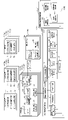
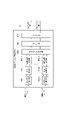
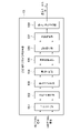
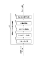
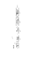
- FIG. 1 is a schematic diagram showing a configuration example of a free-space optical communication system according to this embodiment.
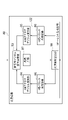
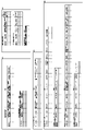
- FIG. 2 is a block diagram showing a configuration example of a free-space optical communication system according to this embodiment.
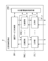
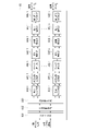
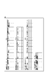
- FIG. 3 is a diagram showing a detailed block configuration example of the free-space optical communication device.
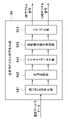
- FIG. 4 is a diagram showing a detailed block configuration example of the optical space communication management device.
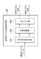
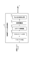
- FIG. 5 is a block diagram showing a configuration example of the optical communication unit according to this embodiment.
- FIG. 6 is a diagram showing a detailed block configuration example of an optical transmitter that employs the digital coherent optical communication system.
- FIG. 1 is a schematic diagram showing a configuration example of a free-space optical communication system according to this embodiment.
- FIG. 2 is a block diagram showing a configuration example of a free-space optical communication system according to this embodiment.
- FIG. 3 is a diagram showing a detailed block configuration example of the free-space optical communication device.
- FIG. 4 is a diagram showing
- FIG. 7 is a diagram showing a configuration example of a transmission side digital signal processing unit when the optical communication unit adopts the wavelength division multiplexing method and the digital coherent optical communication method.
- FIG. 8 is a diagram showing a configuration example of a transmission-side digital signal processing unit when adopting the Nyquist wavelength division multiplexing system and the digital coherent optical communication system.
- FIG. 9 is a diagram showing a configuration example of a transmission-side digital signal processing unit that employs the Nyquist frequency division multiplexing method.
- FIG. 10 is a diagram showing a specific configuration example of a transmission-side digital signal processing unit when adopting the orthogonal frequency division multiplexing method and the digital coherent optical communication method.
- FIG. 11 is a diagram showing a configuration example of an optical transmitter that employs an optical intensity modulation method.
- FIG. 12 is a diagram showing a configuration example of a transmission-side digital signal processing section that employs the optical intensity modulation method.
- FIG. 13 is a diagram showing a detailed block configuration example of an optical transmitter that employs the optical phase modulation method.
- FIG. 14 is a diagram showing a configuration example of a transmission-side digital signal processing section that employs an optical phase modulation method.
- FIG. 15 is a diagram showing a detailed block configuration example of an optical receiver that employs the digital coherent optical communication system.
- FIG. 16 is a diagram showing a specific configuration example of the receiving side digital signal processing unit when the optical communication unit adopts the wavelength division multiplexing method.
- FIG. 17 is a diagram showing a configuration example of a digital signal processing unit on the receiving side when the optical communication unit adopts the Nyquist wavelength division multiplexing system.
- FIG. 18 is a diagram showing a configuration example of a reception-side digital signal processing section that employs the Nyquist frequency division multiplexing method.
- FIG. 19 is a diagram showing a configuration example of a reception-side digital signal processing section that employs the orthogonal frequency division multiplexing method.
- FIG. 20 is a diagram showing a detailed block configuration example of an optical receiver that employs the optical intensity modulation method.
- FIG. 21 is a diagram showing a configuration example of a receiving-side digital signal processing unit that employs the optical intensity modulation method.
- FIG. 22 is a diagram showing a detailed block configuration example of the first embodiment of the optical receiver that employs the optical phase modulation method.
- FIG. 23 is a diagram showing a configuration example of a reception-side digital signal processing section that employs the optical phase modulation method.
- FIG. 24 is a diagram showing a detailed block configuration example of the second form of the optical receiver that employs the optical phase modulation method.
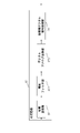
- FIG. 25 is a diagram showing a sequence example for explaining the optical space communication management function according to this embodiment.
- FIG. 26 is a diagram showing an example of the line measurement information database and the like according to this embodiment.
- FIG. 27 is a diagram showing an example of the position information database according to this embodiment.
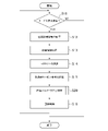
- FIG. 28 is an example of a flowchart showing the processing procedure of the optical space communication management function according to this embodiment.
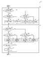
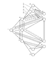
- FIG. 29 is an example of a flowchart showing a processing procedure of line parameter calculation processing according to the present embodiment. It is an example of a diagram for explaining the effect of the present embodiment.
- a plurality of circuit configurations such as between a geostationary orbit satellite and a low earth orbit satellite, between two low earth orbit satellites, and between a device installed on the ground and a geostationary orbit satellite or a low earth orbit satellite It is particularly intended for optical space communications between satellites where there are
- FIG. 1 shows a configuration example of a free-space optical communication system according to this embodiment.
- a free space optical communication system to which the present invention is applied is a non-uniform communication system comprising a geostationary orbit satellite 5 in geostationary orbit, low earth orbit satellites 6A to 6C in low earth orbit, and flying objects 7A to 7D flying in the air. It comprises a terrestrial node group, optical ground stations 3A to 3D and radio ground stations 4A and 4B which are installed on the ground.
- These geostationary orbit satellites 5, low earth orbit satellites 6A to 6C, flying objects 7A to 7D, optical ground stations 3A to 3D and wireless ground stations 4A and 4B are line-controlled by optical space communication management devices 1 (1A and 1B), respectively. be done.
- FIG. 2 is a block diagram showing a configuration example of a free space optical communication system to which the present invention is applied.
- the free space optical communication system includes at least one of a geostationary orbit satellite 5, a low earth orbit satellite 6, and a flying object 7 as a non-terrestrial node group, and one or more mounted on an optical ground station 3.
- communication service data based on the service request and line measurement information received from the optical space communication device 2, the geostationary orbit satellite 5, the low earth orbit satellite 6 and the flying object 7 of the non-terrestrial node group, and the optical ground station 3 and a free-space optical communication management device 1 that performs line control based on line path information and line parameters for transmission and reception.
- a pair of free-space optical communication devices 2 transmit and receive communication service data via a line for optical space communication
- a wireless ground station 4 transmits and receives line information related to communication service data via a wireless control line such as radio waves. conduct.
- the optical space communication management device 1 may further perform line control based on the environment information and the weather information received from the environmental weather information collection device 8 .
- the line information includes service requests, line measurement information, line route information, and line parameters for each of a plurality of lines related to the geostationary orbit satellite 5, low earth orbit satellite 6, flying object 7, and optical ground station 3 of the non-terrestrial node group. include.
- the geostationary orbit satellite 5 is a satellite located in a geostationary orbit, and includes one or more optical space communication devices 2, a geostationary orbit satellite control unit 51 for controlling the geostationary orbit satellite 5, and a geostationary orbit satellite communication unit 52.
- the low-orbit satellites 6 (6A to 6C) are satellites located in low-earth orbit, and include one or a plurality of optical space communication devices 2, a low-orbit satellite control unit 61 for controlling the low-orbit satellites 6, and a and an orbital satellite communication unit 62 .
- the flying object 7 (7A to 7D) is an aircraft, a drone, a high altitude pseudosatellite (HAPS: High Altitude Platform Station), a helicopter, an unmanned aerial vehicle (UAV: Unmanned Aerial Vehicle), etc.
- a space communication device 2 a flying object control unit 71 for controlling the flying object 7 , and a flying object communication unit 72 are provided.
- the geostationary orbit satellite control unit 51, the low earth orbit satellite control unit 61, and the flying object control unit 71 are composed of onboard electronic devices such as FPGA (Field Programmable Gated Array) or CPU (Central Processing Unit). electronic circuit, etc.
- the geostationary orbit satellite control unit 51 performs attitude control of the geostationary orbit satellite 5 in orbit.
- the low-orbit satellite control unit 61 performs attitude control of the low-orbit satellite 6 in orbit.
- the flying object control unit 71 controls the attitude of the flying object 7 in flight.
- a node group including at least one of one or more geostationary orbit satellites 5, one or more low earth orbit satellites 6, and one or more flying objects 7 may be called a non-terrestrial node group.
- the optical ground station 3 (3A to 3D) is a device installed on the ground. It is directly connected by a control line such as a mobile line or an RF feeder link, and the directivity angle (azimuth angle, elevation angle ( An optical ground station control unit 31 for controlling Elevation Angle), and an optical ground station communication unit 32 for communicating line information with the free space optical communication management device 1 .
- the line information includes service requests, line measurement information, line route information, and line parameters for each of a plurality of lines related to the geostationary orbit satellite 5, low earth orbit satellite 6, flying object 7, and optical ground station 3 of the non-terrestrial node group. include.
- the optical ground stations 3 (3A to 3D) may be installed not only on the ground but also on ships on the sea, or may be installed on celestial bodies, planets, and the like.
- the environmental information collecting device 8 (8A, 8B) includes an environmental information collecting unit 801 for collecting environmental information about the environment in which the optical ground station 3 and the flying object 7 are arranged, a weather information collection unit 802 for collecting weather information of the area where the weather information is collected; an environment information database DB6 for storing the environment information collected by the environment information collection unit 801; and an information database DB7.
- the environmental information collection device 8 (8A, 8B) communicates the collected environmental information and weather information to the space optical communication management device 1.
- the environmental information collection unit 801 may be installed on a ship on the ground or on the sea, may be installed on a celestial body, a planet, or the like, or may be installed on a flying object such as an unmanned aerial vehicle or a satellite in outer space.
- the weather information collection unit 802 may collect weather information from the cloud, the Internet, or the like, or may determine weather information from the environment information acquired by the environment information collection unit 801 .
- Environmental information includes environment such as temperature, humidity, wind speed, wind direction, amount of clouds, height of clouds, amount of rain, air pressure, illuminance, and all-sky camera image.
- Environmental information may also include weather information.
- Environmental information includes, for example, all-sky cameras and information collected by environmental sensors such as cloud gauges, cloud height gauges, thermometers, hygrometers, barometers, illuminometers, anemometers, wind vanes, and rain gauges.
- the weather information includes past to present weather such as fine weather, rainy weather, and cloudy weather in each region, and weather forecasts for each region.
- the environmental information database DB6 and the weather information database DB7 are stored in a storage device such as a ROM (Read Only Memory) or hard disk.
- the space optical communication management device 1 includes a line measuring unit 11 for measuring line measurement information of a plurality of lines between the space optical communication devices 2 through which communication service data is transmitted and received, and a line path information for the space optical communication devices 2. and a line control unit 12 for line control based on line parameters, a line parameter calculation unit 10 for calculating line route information and line parameters based on service requests and line measurement information for line control, and an optical ground station 3 and radio ground station 4, a line information communication unit 14 for communicating line information; A service request collection unit 17 connected to the communication unit 14 is provided.
- the line information includes service requests, line measurement information, line route information, and line parameters for each of a plurality of lines related to the geostationary orbit satellite 5, low earth orbit satellite 6, flying object 7, and optical ground station 3 of the non-terrestrial node group.
- the optical space communication management device 1 (1A, 1B) may be installed not only on the ground but also on a ship on the sea, or may be installed on a celestial body, a planet, or the like.
- the line information communication unit 14 communicates with the geostationary orbit satellite 5 and the low earth orbit satellite of the non-terrestrial node group via the optical ground station communication unit 32 of the optical ground station 3 and the wireless ground station communication unit 42 of the wireless ground station 4, which will be described later. 6, the flying object 7 and the optical ground station 3 receive service requests and line measurement information.
- the line information communication unit 14 transmits the received line measurement information to the line measurement unit 11 .
- Service requests received by the line information communication unit 14 are collected by the service request collection unit 17 .
- the service request collection unit 17 stores the collected service requests in the service request information database DB3.
- the line measurement unit 11 stores line measurement information in a line measurement information database DB2, which will be described later.
- the position calculation unit 13 transmits position information calculated based on track information stored in a position information database DB5, which will be described later, to the line parameter calculation unit 10.
- FIG. The line parameter calculator 10 calculates the information stored in the line path information database DB1, the information stored in the line parameter information database DB4, the information stored in the service request information database DB3, and the line measurement information database DB2.
- the location information transmitted from the calculation unit 13 is referred to, and the line route information and line parameters are calculated and transmitted to the line control unit 12 .
- the line parameter calculation unit 10 may further refer to the environment information stored in the environment information database DB6 and the weather information stored in the weather information database DB7 to calculate line route information and line parameters. good.
- the line control unit 12 transmits the line path information and the line parameters to the line information communication unit 14, and the wireless ground station wireless communication unit 41 of the wireless ground station 4, which will be described later, is sent to the free space optical communication device 2 provided in the non-terrestrial node group. , the optical space communication device 2 provided in the optical ground station 3 is controlled via the optical ground station communication unit 32 . Also, the line control unit 12 saves line route information and line parameters in the line route information database DB1 and the line parameter information database DB4.
- the line path information database DB1, the line measurement information database DB2, the service request information database DB3, the line parameter information database DB4, and the location information database DB5 are stored in a storage device such as a ROM (Read Only Memory) or hard disk.
- the line parameter calculation unit 10, line measurement unit 11, line control unit 12, line information communication unit, and position calculation unit 13 are mounted onboard, for example, FPGA (Field Programmable Gated Array) or CPU (Central Processing Unit). It may be an electronic circuit configured by an electronic device capable of performing AI (Artificial Intelligence), a server or a PC capable of machine learning. Also, the line parameter calculation unit 10, the line measurement unit 11, the line control unit 12, the line information communication unit, and the position calculation unit 13 may be collectively configured as an SDN (Software Defined Network) controller.
- SDN Software Defined Network
- the line control unit 12 of the space optical communication management device 1 transmits line route information and line parameters to the optical ground station communication unit 32 of the optical ground station 3 via the line information communication unit 14 . Also, the line control unit 12 of the space optical communication management device 1 transmits line path information and line parameters to a radio ground station communication unit 42 of the radio ground station 4, which will be described later, via the line information communication unit 14.
- FIG. 12 illustrates that the line control unit 12 of the space optical communication management device 1 transmits line route information and line parameters to the optical ground station communication unit 32 of the optical ground station 3 via the line information communication unit 14 .
- the line control unit 12 of the space optical communication management device 1 transmits line path information and line parameters to a radio ground station communication unit 42 of the radio ground station 4, which will be described later, via the line information communication unit 14.
- the radio ground station 4 (4A, 4B) transmits the line information of each line between the plurality of free space optical communication devices 2 to which the communication service data is transmitted and received via the satellite communication control line such as the above-mentioned radio waves.
- a communication device comprising a radio ground station radio communication section 41 , a radio ground station communication section 42 , and a radio ground station control section 43 .
- the wireless ground station communication unit 42 may be configured by an electronic circuit configured by an electronic device that can be mounted on-board, such as an FPGA (Field Programmable Gated Array) or a CPU (Central Processing Unit).
- the radio ground station radio communication unit 41 may be composed of an electronic circuit configured by an electronic device that can be mounted on-board, such as an FPGA (Field Programmable Gated Array) or a CPU (Central Processing Unit). Includes communication devices for data transmission and reception using radio waves for satellite communication and antennas for satellite communication.
- the line information includes service requests, line measurement information, line route information, and line parameters for each of a plurality of lines related to the geostationary orbit satellite 5, low earth orbit satellite 6, flying object 7, and optical ground station 3 of the non-terrestrial node group. include.
- the wireless ground station 4 (4A, 4B) may be installed not only on the ground but also on a ship on the sea, or may be installed on a celestial body, a planet, or the like.
- the radio ground station radio communication unit 41 communicates line information between the geostationary orbit satellite communication unit 52 of the geostationary orbit satellite 5, the low earth orbit satellite communication unit 62 of the low earth orbit satellite 6, or the flying object communication unit of the flying object 7 and 72. I do.
- the radio ground station control unit 43 controls the orientation angles (azimuth and elevation) necessary for optical space communication in the radio ground station 4 .
- the radio ground station communication unit 42 communicates line information with the line information communication unit 14 of the free space optical communication management device 1 .
- the line information includes service requests, line measurement information, line route information, and line parameters for each of a plurality of lines related to the geostationary orbit satellite 5, low earth orbit satellite 6, flying object 7, and optical ground station 3 of the non-terrestrial node group. include.
- the wireless ground station 4 and the optical space communication management device 1 are connected via a control line such as a wired or wireless LAN (Local Area Network), a terrestrial mobile line, or an RF feeder link.
- a control line such as a
- the space optical communication device 2 is controlled and processed based on the line control from the space optical communication management device 1, and includes optical units 21_1, . . . 202_n are provided.
- the optical space communication device control unit 22 and the communication service processing unit 23 are configured by an electronic circuit configured by an electronic device that can be mounted on-board, such as an FPGA (Field Programmable Gated Array) or a CPU (Central Processing Unit).
- the optical unit 21 is composed of, for example, an optical antenna such as a lens, and optical elements such as a mirror, an optical sensor, and an optical filter.
- the optical unit 21 shapes or converges a light beam transmitted from a satellite, a flying object, or the like with an optical antenna, and further controls the capture and tracking orientation of the light beam in accordance with the satellite, the flying object, or the like.
- the space optical communication device control unit 22 controls the optical space via the optical ground station communication unit 32 and the line information communication unit 14 of the space optical communication management device 1 . It acquires line route information and line parameters from the line control unit 12 of the communication management device 1 and accepts line control. , 21_n, optical communication units 202_1, . . . , 202_n and communication service processing unit 23 parameters and control route information.
- the optical space communication device control unit 22 sends the optical ground station communication unit 32 to the line information communication unit 14 of the space optical communication management device 1. It transmits a service request and line measurement information for the line through station 3 .
- the line information communication unit 14 transmits line measurement information to the line measurement unit 11 of the space optical communication management device 1, and stores service requests for lines via the optical ground station 3 in the service request DB.
- the free-space optical communication device control unit 22 controls the geostationary orbit satellite communication unit 52 of the geostationary orbit satellite 5 or the low earth orbit satellite communication unit of the low earth orbit satellite 6. 62 or the flying object communication unit 72 of the flying object 7, the radio ground station radio communication unit 41 of the radio ground station 4, and the radio ground station communication unit 42 of the radio ground station 4, to the space optical communication management device 1. Send request and line metering information.
- the space optical communication device control unit 22 controls the optical ground station communication unit 32 and the line information communication unit 14 of the space optical communication management device 1. It receives the line path information and line parameters of the line via the optical ground station 3 from the line control unit 12 of the space communication management device 1 .
- the free-space optical communication device control unit 22 controls the geostationary orbit satellite communication unit 52 of the geostationary orbit satellite 5 or the low earth orbit satellite communication unit of the low earth orbit satellite 6.
- the line control of the space optical communication management device 1 It receives line route information and line parameters from the unit 12 .
- the communication service processing unit 23 processes communication service data transmitted and received via lines, sets routing, allocates communication bands, and sets whether or not to use encryption.
- the communication service processing unit 23 performs communication from a ground system network including a mobile communication network and an optical backbone communication network of a business company connected to a cloud or the like. Based on the service data, a service request is transmitted to the free-space optical communication device control unit 22 .
- the communication service processing unit 23 receives communication services generated by users on board the ship.
- a service request is transmitted to the optical space communication device control unit 22 based on the data or marine resource exploration images acquired by the user equipment installed on the ship.
- the communication service processing unit 23 receives information from users staying near the planet or celestial body.
- a service request is transmitted to the free space optical communication device control unit 22 based on communication service data generated from the device or a planet image or celestial body image acquired by a user device installed near a planet or celestial body.
- the space optical communication device control unit 22 transmits a service request to the space optical communication management device 1 via a control line such as a wired or wireless LAN.
- the space optical communication device control unit 22 controls the geostationary orbit of the non-terrestrial node group.
- Service requests for one or more lines and line measurement information from satellites 5, low-orbit satellites 6, and flying objects 7 are transmitted through a communication service processing unit 23, together with communication service data, as packets, pilot signals, and the like. It may be transmitted to the ground station 3 or other non-terrestrial node group geostationary orbit satellites 5, low earth orbit satellites 6 and flying objects 7.
- the space optical communication device control unit 22 receives 1 Alternatively, service requests and line measurement information for a plurality of lines may be received via the communication service processing unit 23 together with communication service data as packets, pilot signals, and the like. The space optical communication device control unit 22 transmits the received service request and line measurement information to the space optical communication management device 1 via the optical ground station communication unit 32 .
- the space optical communication device control unit 22 controls the geostationary orbit satellite 5, the low earth orbit satellite 6, and the flying object 7 of the non-terrestrial node group.
- line path information and line parameters of one or more lines may be transmitted via the communication service processing unit 23 together with communication service data as packets, pilot signals, and the like.
- the space optical communication device control unit 22 receives line path information and line parameters from the space optical communication management unit 1 via the optical ground station communication unit 32 .
- the space optical communication device control unit 22 controls the geostationary orbit of the non-terrestrial node group.
- Line path information and line parameters of one or more lines from the satellite 5, the low earth orbit satellite 6, and the flying object 7 are optically transmitted together with the communication service data as packets and pilot signals via the communication service processing unit 23.
- the signal may be received by the ground station 3 or the geostationary orbit satellite 5, the low earth orbit satellite 6, and the flying object 7 of the non-terrestrial node group.
- the communication service processing unit 23 is provided in the non-terrestrial node group.
- User data such as earth observation images obtained by user equipment such as invisible optical sensors and synthetic aperture radar (SAR: Synthetic Aperture Radar), or mobile communication networks and optical backbone communication networks of operating companies connected to the cloud, etc.
- a service request is transmitted to the free-space optical communication device control unit 22 based on communication service data from the terrestrial network or communication service data generated by a user on board the flying object 7 or the like.
- the optical space communication device control unit 22 sends the transmitted service request to the geostationary orbit satellite communication unit 52 of the geostationary orbit satellite 5, the low earth orbit satellite communication unit 62 of the low earth orbit satellite 6, or the flying object communication unit 72 of the flying object 7, It is transmitted to the space optical communication management device 1 via the radio ground station radio communication section 41 of the radio ground station 4 and the radio ground station communication section 42 of the radio ground station 4 .
- Geostationary orbit satellites 5, low earth orbit satellites 6 (6A to 6C), and flying objects 7 (7A to 7D) receive communication service data from users connected to terrestrial networks, aircraft and drones of flying objects 7, and high-altitude satellites.
- RF communication equipment not shown, may be provided that aggregates communication service data from pseudolites, helicopters, unmanned aerial vehicles, and the like.
- Communication service data aggregated by an RF communication device may be transmitted to the communication service processing unit 23 and processed by the communication service processing unit 23 .
- the optical space communication device 2 includes an optical communication unit 201 and an optical unit 21 corresponding to each line when there are a plurality of lines. may be provided.
- one optical communication unit 202_1 and one optical unit 21_1 are provided.
- the optical communication unit 202 may be composed of a digital coherent optical transceiver, an optical phase modulation optical transceiver, an optical intensity modulation optical transceiver, etc. that can adaptively switch line parameters.
- optical amplification and adaptive switching and setting of line parameters can be performed for each line.
- adaptive switching and setting of line parameters specific to the optical unit 21, such as the beam divergence angle may be performed for each line.
- the free-space optical communication device 2 in the form of FIG. 3 further includes a communication service processing unit 201 and a free-space optical communication device control unit 205 .
- the communication service processing unit 201 is connected to the optical communication units 202_1, .
- the number of communication service processing units 201 is one in order to be able to process a plurality of lines. For example, when there are n lines, n communication service processing units 201_1, . may be provided.
- the communication service processing unit 201 may be configured with a hardware reconfigurable SDN (Software Defined Network) switch or the like.
- the communication service processing unit 201 also supports communication protocols such as IP (Internet Protocol), TCP (Transmission Control Protocol), UDP (User Datagram Protocol), RIP (Routing Information Protocol), OSPF (Open Shortest Path First), MPLS (Multi-Protocol Label Switching), GMPLS (Generalized Multi-Protocol Label Switching), DTN (Delay Tolerant Networking), and other routing control technologies may be provided.
- IP Internet Protocol
- TCP Transmission Control Protocol
- UDP User Datagram Protocol
- RIP Rastering Information Protocol
- OSPF Open Shortest Path First
- MPLS Multi-Protocol Label Switching
- GMPLS Generalized Multi-Protocol Label Switching
- DTN Delay Tolerant Networking
- Ethernet data of communication standards called Ethernet such as 1GbE (1G Ethernet), 10GbE (10G Ethernet), 100GbE (100G Ethernet), 400GbE (400G Ethernet), data of optical transmission standards such as OTN (Optical Transport Network), Data from mobile networks such as 5G (5th Generation) may also be handled.
- Ethernet data of communication standards called Ethernet such as 1GbE (1G Ethernet), 10GbE (10G Ethernet), 100GbE (100G Ethernet), 400GbE (400G Ethernet
- OTN Optical Transport Network
- 5G (5th Generation) Data from mobile networks such as 5G (5th Generation
- the communication service processing unit 201 Transmission of service requests and line measurement information to geostationary orbit satellites 5, low earth orbit satellites 6, and flying objects 7, and reception of line path information and line parameters from the optical ground station 3 are transmitted together with communication service data in packets and pilots. It may be included as a signal or the like. Service requests, line measurement information, line path information, and line parameters are transmitted and received between the communication service processing unit 201 and the free-space optical communication device control unit 205 .
- the communication service processing unit 201 provides line route information to the geostationary orbit satellite 5, the low earth orbit satellite 6, and the flying object 7 of the non-terrestrial node group. and transmission of line parameters, and reception of service requests and line measurement information from geostationary orbit satellites 5, low earth orbit satellites 6, and flying objects 7, which are non-terrestrial node groups, together with communication service data as packet signals. good too. Service requests, line measurement information, line path information, and line parameters are transmitted and received between the communication service processing unit 201 and the free-space optical communication device control unit 205 .
- the free-space optical communication device control unit 205 performs various controls such as collection of line measurement information from the optical unit 21 and the optical communication unit 202, control of line parameters, and setting of line route information.
- the optical space communication management device 1 includes a geostationary orbit satellite 5, a low earth orbit satellite 6, a flying object 7, and an optical ground station 3, which are non-terrestrial node groups. Receive line measurement information and service requests from one or more lines, and also relate to geostationary orbit satellites 5, low earth orbit satellites 6 and flying objects 7 and optical ground stations 3 of the non-terrestrial node group. line route information and line parameters may be transmitted to the other line.
- the optical space communication management device 1 provides the line path information database DB1, the line measurement information database DB2, the service request information database DB3, and the line parameter information database DB4 to the line parameter calculator 10. , and position information database DB5, respectively, and a line control unit 12 is connected to a line path information database DB1 and a line parameter information database DB4.
- a line information communication unit 14 is connected to the line control unit 12, and a line measurement unit 11 is connected to the line measurement information database DB2.
- a position calculator 13 is connected to the position information database DB5.
- the line measurement unit 11 can receive and measure line measurement information for each of multiple lines of the geostationary orbit satellite 5, the low earth orbit satellite 6, and the flying object 7.
- the service request information database DB3 can similarly acquire service requests for a plurality of lines of the geostationary orbit satellite 5, the low earth orbit satellite 6, and the flying object 7, respectively.
- the line control unit 12 and the line information communication unit 14 provide line path information and line parameters for each of the plurality of lines related to the optical ground station 3, the geostationary orbit satellite 5, the low earth orbit satellite 6, and the flying object 7. can be sent.
- the optical space communication management device 1 provides the line path information database DB1, the line measurement information database DB2, the service request information database DB3, and the line parameter information database to the line parameter calculator 10.
- DB4 location information database DB5, environmental information database DB6 and weather information database DB7 of environmental weather information collection device 8 are connected, respectively, and line control unit 12 is connected to line route information database DB1 and line parameter information database DB4. do.
- a line information communication unit 14 is connected to the line control unit 12, and a line measurement unit 11 is connected to the line measurement information database DB2.
- a position calculator 13 is connected to the position information database DB5.
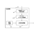
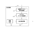
- the optical communication unit 202 converts one piece of communication service data from the communication service processing unit 23 into an optically modulated signal of one wavelength and outputs it to the optical unit 21 will be described with reference to FIG. 5, the case where the optical communication unit 202 converts the optical modulated signal for one wavelength input from the optical unit 21 into one piece of communication service data and transmits it to the communication service processing unit will be described.
- FIG. 5 is a block diagram showing a configuration example of the optical communication unit according to this embodiment.
- the optical communication unit 202 includes an optical transmitter 81 that converts communication service data into an optical modulated signal and transmits it, an optical receiver 82 that converts the optical modulated signal into communication service data and receives it, and an optical modulated signal received from the optical unit 21 .
- An optical amplifying device 83 is provided as a device for amplifying a signal and an optically modulated signal to be transmitted to the optical unit 21 .
- 202 can handle wavelength division multiplexing (WDM) optical modulated signals in which optical modulated signals of multiple wavelengths are multiplexed.
- WDM wavelength division multiplexing
- the optical transmitter 81 generates an optical modulated signal for one wavelength from one communication service data from the communication service processing unit 23 .
- the high-output optical amplifier 92 included in the optical amplifying device 83 amplifies the modulated optical signal to a high output.
- the low-noise optical amplifier 100 included in the optical amplification device 83 performs low-noise amplification of the optical modulated signal for one wavelength.
- the low-noise amplified optical modulated signal for one wavelength is converted into one piece of communication service data by the optical receiver 82 .
- the high-output optical amplifier 92 and the low-noise optical amplifier 100 may be one device.
- the optical amplifying device 83 may be omitted, or may be composed of at least one of the high-output optical amplifier 92 and the low-noise optical amplifier 100 included in the optical amplifying device 83 .
- the optical unit 21 may be directly switched to the optical multiplexer/demultiplexer 101 , or the optical unit 21 may be switched directly to the optical transmitter 81 and the optical receiver 82 .
- the demultiplexing unit 103 of the optical multiplexing/demultiplexing device 101 included in the optical communication unit 202_1 and the multiplexing unit 102 of the optical multiplexing/demultiplexing device 101 included in the optical communication unit 202_2 are connected.
- FIG. 6 is a diagram showing a detailed block configuration example of the optical transmitter 81 when, for example, a digital coherent optical communication system is adopted.
- the optical transmitter 81 includes a transmission-side digital signal processing unit 84, an I-phase digital-analog converter 85, a Q-phase digital-analog converter 87, A transmission light source 86 and an IQ optical modulator 121 are provided.
- the IQ optical modulator 121 includes an I-phase optical modulator 88 , an optical splitter 89 , a Q-phase optical modulator 90 , a ⁇ /2 phase shifter 131 and an optical combiner 91 .
- the transmission-side digital signal processing unit 84 generates a modulated signal based on one piece of communication service data.
- the modulated signal consists of an I-phase digital signal and a Q-phase digital signal, which are separately input to the IQ optical modulator 121 .
- error correction coding may be performed on one communication service data, and digital processing such as digital filtering, signal deterioration compensation, modulator non-linear compensation, and linear equalization processing may be performed.
- the transmission-side digital signal processing unit 84 uses, for example, a digital multiplexing method such as an orthogonal frequency division multiplexing (OFDM) method or a Nyquist-Frequency Division Multiplexing (N-FDM) method.
- a modulated signal generated based on communication service data is used as one subcarrier signal, and after multiplexing a plurality of subcarrier signals, the signal is separated into an I-phase digital signal and a Q-phase digital signal, which are sent to the IQ optical modulator 121 respectively. can be entered.
- the optical transmitter 81 can generate an optically modulated signal containing a plurality of communication service data for one wavelength.
- error correction coding may be performed on one communication service data, and digital processing such as digital filtering, signal deterioration compensation, modulator non-linear compensation, and linear equalization processing may be performed.
- the I-phase communication service data is converted from the I-phase digital signal to the I-phase electrical signal by the I-phase digital-analog converter 85, and the I-phase electrical signal is converted to the I-phase optical signal by the I-phase optical modulator 88 of the IQ optical modulator 121. Modulated signal.
- the Q-phase communication service data is converted from the Q-phase digital signal to the Q-phase electric signal by the Q-phase digital-analog converter 87, and the Q-phase electric signal is sent to the Q-phase optical modulator 90 of the IQ optical modulator 121 and the phase of the light. is converted to a Q-phase optical modulation signal by a ⁇ /2 phase shifter 131 that shifts to ⁇ /2.
- the optical combiner 91 combines the I-phase optical modulated signal input from the I-phase optical modulator 88 and the Q-phase optical modulated signal input from the Q-phase modulator 90 to generate an optical modulated signal for one wavelength. to generate
- the unmodulated light output from the transmission light source 86 is split by the optical splitter 89. Two unmodulated lights are used.
- FIG. 7 is a diagram showing a specific configuration example of the transmission-side digital signal processing unit 84 when the optical communication unit adopts the wavelength division multiplexing method and the digital coherent optical communication method.
- the transmission side digital signal processing section 84 includes an error correction coding section 841 , a multilevel modulation section 842 and a resampling section 843 .
- the error correction coding unit 841 applies error correction coding processing to communication service data.
- the multi-level modulation unit 842 performs so-called multi-level modulation, which modulates communication service data subjected to error correction coding processing by the error correction coding unit 841 so that one modulation symbol can take two or more signal points. apply.
- the multilevel modulation section 842 may perform differential encoding processing.
- a resampling unit 843 outputs an I-phase digital signal and a Q-phase digital signal obtained by performing various resampling processes on the multi-value modulated signal that has been multi-value modulated by the multi-value modulation unit 842 .
- an interleaver unit (not shown) that performs processing for changing the order of bit data included in communication service data.
- FIG. 8 is a diagram showing a configuration example of the transmission side digital signal processing unit 84 when the optical communication unit adopts the Nyquist wavelength division multiplexing method and the digital coherent optical communication method.
- the configurations of the error correction coding unit 841, the multilevel modulation unit 842, and the resampling unit 843 are the same as in FIG.
- the Nyquist filter section 844 is a filter that performs waveform shaping for Nyquist wavelength division multiplexing on the multi-level modulated signal that has been multi-level modulated by the multi-level modulation section 842 .
- the modulator nonlinearity compensator 845 compensates for the nonlinearity of the I-phase optical modulator 88 of the IQ optical modulator 121 and the Q-phase optical modulator 90 of the IQ optical modulator 121 .
- the transmission-side digital signal processing unit 84 may be embodied in the form shown in FIG.
- FIG. 9 is a diagram showing a configuration example of the transmission-side digital signal processing section 84 that employs the Nyquist frequency division multiplexing method.
- the form shown in FIG. 9 employs the Nyquist FDM (Frequency Division Multiplexing) system, multiplexes communication service data, and separates and outputs an I-phase digital signal and a Q-phase digital signal.
- Nyquist FDM Frequency Division Multiplexing
- An error correction coding unit 841, a multilevel modulation unit 842, a frequency conversion unit 847, and a Nyquist filter unit 844 are assigned to each of the supplied communication service data. For example, when communication service data SD_1 is supplied, various processes are performed by an error correction encoder 841_1, a multilevel modulator 842_1, a frequency converter 847_1, and a Nyquist filter 844_1.
- communication service data SD_2 when communication service data SD_2 is supplied, various processing is performed by an error correction coding unit 841_2, a multilevel modulation unit 842_2, a frequency conversion unit 847_2, and a Nyquist filter unit 844_2.
- various processes are performed by an error correction coding unit 841_n, a multilevel modulation unit 842_n, a frequency conversion unit 847_n, and a Nyquist filter unit 844_n.
- . . 847_n perform frequency conversion on the subcarrier multi-level modulated signal output from the multi-level modulation section and output this to the Nyquist filter section 844 .
- the transmission-side digital signal processing section 84 that employs this Nyquist FDM system further includes a power allocation section 848 , a subcarrier multiplexing section 849 , an inverse frequency conversion section 850 and a resampling section 843 .
- a power allocation unit 848 divides the subcarrier multi-level modulated signal output from the Nyquist filter unit 844 into subcarrier Power is assigned to each multilevel modulation signal.
- the subcarrier multiplexing section 849 multiplexes the subcarrier multilevel modulated signal supplied from the power allocation section 848 into subcarriers.
- the inverse frequency conversion section 850 performs inverse frequency conversion on the subcarrier-multiplexed signal, which is the opposite of the frequency conversion section 847 .
- the signal subjected to the inverse frequency conversion in this manner is subjected to various resampling processes in the resampling section 843 and output as an I-phase digital signal and a Q-phase digital signal.
- the transmission-side digital signal processing unit 84 may be embodied in the form shown in FIG.
- FIG. 10 is a diagram showing a configuration example of the transmission-side digital signal processing section 84 that employs the orthogonal frequency division multiplexing method and the digital coherent optical communication method.
- the form shown in FIG. 10 employs the OFDM system, multiplexes communication service data, separates the data into an I-phase digital signal and a Q-phase digital signal, and outputs the signals.
- the transmission-side digital signal processing unit 84 that employs the OFDM method.
- An error correction coding unit 841, a multilevel modulation unit 842, and a frequency conversion unit 847 are assigned to each of the supplied communication service data.
- the transmitting side digital signal processing section 84 that employs this OFDM system includes a subcarrier multiplexing section 849 , a CP adding section 851 and a resampling section 843 .
- the CP adding section 851 adds a cyclic prefix (CP) to the subcarriers obtained by inverse frequency converting the multi-level modulated signal output from the multi-level modulating section 842 in the inverse frequency converting section 850 .
- CP cyclic prefix
- the signal to which the CP is added in this way is subjected to various resampling processes in the resampling section 843, and is output as an I-phase digital signal and a Q-phase digital signal.
- the optical transmitter 81 shown in FIG. 6 and the transmission side digital signal processing unit 84 shown in FIGS. 7 to 10 show the case where the optically modulated signal is only a single polarized wave. It may be configured in the case of In this case, the optical modulated signal from the optical transmitter 81 for the X polarized wave and the optical modulated signal for the Y polarized wave from the optical transmitter 81 are combined by the polarization combiner, and the optical modulated signal of polarization multiplexing is obtained. is output. Also, the transmission-side digital signal processing unit 93 is configured to generate an I-phase digital signal and a Q-phase digital signal for the X-polarized wave, and an I-phase digital signal and a Q-phase digital signal for the Y-polarized wave.
- FIG. 11 is a diagram showing a detailed block configuration example of the optical transmitter 81 when the optical intensity modulation method is adopted.
- the optical transmitter 81 includes a transmission-side digital signal processor 84, a digital-analog converter 870, a transmission light source 86, and an optical intensity modulator 900 when the optical intensity modulation method is employed. .
- the digital-to-analog converter 870 converts the digital signal of the communication service data output from the transmission-side digital signal processor 84 into an electrical signal.
- the optical intensity modulator 900 modulates the intensity of the communication service data that has been converted into an electrical signal by the digital-to-analog conversion section 87, and produces an optically modulated signal.
- FIG. 12 is a diagram showing a configuration example of the transmission-side digital signal processing section 84 that employs the optical intensity modulation method.
- the transmission-side digital signal processing unit 84 includes an error correction coding unit 841, a multilevel modulation unit 842, a digital filter unit 846, and a resampling unit as shown in FIG. 843.
- the transmitting side digital signal processing unit 84 generates a modulated signal based on one piece of communication service data, for example, when the optical intensity modulation method is adopted.
- the modulated signal is a digital signal and is input to the optical intensity modulator.
- error correction coding may be performed on one communication service data, and digital processing such as digital filtering, signal deterioration compensation, modulator non-linear compensation, and linear equalization processing may be performed. Further, after the error correction coding unit 841, there may be an interleaver unit (not shown) that performs processing for changing the order of bit data included in communication service data.
- FIG. 13 is a diagram showing a detailed block configuration example of the optical transmitter 81 when, for example, the optical phase modulation method is adopted.
- the optical transmitter 81 includes a transmission-side digital signal processor 84, a digital-analog converter 870, a transmission light source 86, and an optical phase modulator 901 when the optical phase modulation method is adopted.
- the optical phase modulator 901 modulates the phase of the communication service data that has been converted into an electrical signal by the digital-to-analog conversion section 87, thereby producing an optically modulated signal.
- FIG. 14 is a diagram showing a configuration example of the transmission-side digital signal processing section 84 that employs the optical phase modulation method.
- the transmission-side digital signal processing unit 84 is subjected to error correction coding processing by an error correction coding unit 841 and error correction coding processing by the error correction coding unit 841 as shown in FIG.
- a phase modulation unit 852 for phase-modulating communication service data so that one modulation symbol can take two signal points, a digital filter unit 846 and a resample unit 843 are provided.
- the phase modulation section 852 may perform differential encoding processing.
- the transmission side digital signal processing unit 84 generates a modulated signal based on one piece of communication service data when the optical phase modulation method is adopted.
- the modulated signal is a digital signal and is input to the optical intensity modulator.
- error correction coding may be performed on one communication service data, and digital processing such as digital filtering, signal deterioration compensation, modulator non-linear compensation, and linear equalization processing may be performed.
- interleaver unit (not shown) that performs processing for changing the order of bit data included in communication service data.
- FIG. 15 is a diagram showing a detailed block configuration example of the optical receiver 82 that employs the digital coherent optical communication system.
- the optical receiver 82 when adopting the digital coherent optical communication system includes a receiving side digital signal processing section 93, an I-phase analog-to-digital converter 94, a Q-phase analog-to-digital converter 95, and a local light source. 97 and a coherent light detector 122 .
- the coherent photodetector 122 includes an I-phase balanced photodetector 96 , a Q-phase balanced photodetector 98 and an optical frequency mixer 99 .
- the optical frequency mixer 99 utilizes the non-modulated light output from the local light source 97 and causes it to interfere with the low-noise amplified optical modulated signal to produce an I-phase optical modulated signal and a Q-phase optical modulated signal. separate into The I-phase optical modulated signal is detected by an I-phase balance photodetector 96 and becomes an I-phase electrical signal. The I-phase electrical signal is converted to an I-phase digital signal by the I-phase analog-to-digital converter 94 .
- the Q-phase optical modulated signal is detected by the Q-phase balanced photodetector 98 and becomes a Q-phase electrical signal.
- the Q-phase electrical signal is converted into a Q-phase digital signal by the Q-phase balance photodetector 98 .
- the receiving side digital signal processing unit 93 converts the modulated signal synthesized from the I-phase digital signal and the Q-phase digital signal into one piece of communication service data.
- the I-phase digital signal and the Q-phase digital signal are output from the I-phase balanced photodetector 96 and the Q-phase balanced photodetector 98 of the coherent photodetector 122 .
- error correction decoding may be performed on one communication service data, and digital processing such as digital filtering, frequency estimation, phase estimation, and signal degradation compensation such as adaptive equalization may be performed.
- the digital signal processing unit 93 on the receiving side is digitally multiplexed I-phase digital signal such as Orthogonal Frequency Division Multiplexing (OFDM) or Nyquist-Frequency Division Multiplexing (N-FDM).
- the signal and the Q-phase digital signal can be separated into multiple subcarriers, and the modulated signal as one subcarrier can be converted into one communication service data.
- the I-phase digital signal and the Q-phase digital signal are output from the I-phase balanced photodetector 96 and the Q-phase balanced photodetector 98 of the coherent photodetector 122 .
- the optical receiver 82 can convert an optical modulated signal for one wavelength into a plurality of pieces of communication service data. Note that error correction decoding may be performed on one communication service data, and digital processing such as digital filtering, frequency estimation, phase estimation, and signal degradation compensation such as adaptive equalization may be performed.
- FIG. 16 is a diagram showing a specific configuration example of the receiving side digital signal processing section 93 when the optical communication section adopts the wavelength division multiplexing method.
- This receiving side digital signal processing unit 93 includes a resample unit 931, a clock extraction unit 932, an adaptive equalization unit 934, a frequency estimation unit 935, a phase estimation unit 936, a multilevel demodulation unit 937, and an error correction unit 937. and a decoding unit 938 .
- the resampling unit 931 is supplied with the I-phase digital signal and the Q-phase digital signal, and performs various resampling processes on these signals.
- a clock extractor 932 extracts clocks from the I-phase digital signal and the Q-phase digital signal resampled by the resampler 931 .
- the adaptive equalization unit 934 performs equalization processing on the input I-phase digital signal and Q-phase digital signal, respectively, and detects power fluctuation information to be stored in a power fluctuation information table TB4, which will be described later.
- the frequency estimator 935 performs frequency estimation required for demodulation of the input I-phase digital signal and Q-phase digital signal, and detects frequency fluctuation information to be stored in a frequency fluctuation information table TB3, which will be described later.
- the phase estimator 936 performs phase estimation necessary for demodulation of the I-phase digital signal and the Q-phase digital signal, and detects phase fluctuation information to be stored in a phase fluctuation information table TB5, which will be described later.
- the multi-level demodulator 937 demodulates the I-phase digital signal and the Q-phase digital signal, which are multi-level modulated signals, into one piece of communication service data.
- the multilevel demodulator 937 may perform differential decoding processing.
- the error correction decoding section 938 performs error correction decoding processing on the communication service data obtained by the multilevel demodulation section 937 .
- a deinterleaver (not shown) that performs reverse operation processing of bit data exchange on communication service data that has been subjected to bit data order exchange processing in an interleaver (not shown) prior to the error correction decoding unit 938 .
- FIG. 17 is a diagram showing a configuration example of the receiving side digital signal processing section 93 when the optical communication section adopts the Nyquist wavelength division multiplexing system.
- 17 includes a resampler 931, a clock extractor 932, a matched filter 933, an adaptive equalizer 934, a frequency estimator 935, and a phase estimator 936. , a multilevel demodulator 937 and an error correction decoder 938 .
- the matched filter section 933 is a filter necessary for demodulation.
- the configurations of the resampler 931, the clock extractor 932, the adaptive equalizer 934, the frequency estimator 935, the phase estimator 936, the multilevel demodulator 937, and the error correction decoder 938 are shown in FIG. , so that the same reference numerals are given to omit the description below.
- a deinterleaver (not shown) that performs reverse operation processing of bit data exchange on communication service data that has been subjected to bit data order exchange processing in an interleaver (not shown) prior to the error correction decoding unit 938 . There may be a leaver section.
- the reception-side digital signal processing unit 93 may be embodied in the form shown in FIG.
- FIG. 18 is a diagram showing a configuration example of the reception-side digital signal processing section 93 that employs the Nyquist frequency division multiplexing method.
- communication service data is multiplexed under the Nyquist FDM (Frequency Division Multiplexing) method in the transmission-side digital signal processing unit 84, and the data is converted into an I-phase digital signal and a Q-phase digital signal. It separates from the original communication service data and outputs it.
- Nyquist FDM Frequency Division Multiplexing
- the receiving-side digital signal processing unit 93 can separate and output from 1 to a maximum of n pieces of communication service data.
- the multiplexed signal input to the receiving side digital signal processing unit 93 reaches the frequency conversion unit 939 through the resampling unit 931 and the frequency estimation unit 935 .
- the frequency conversion unit 939 performs frequency conversion and supplies the multiplexed I-phase digital signal and Q-phase digital signal for each communication service data to the matched filter units 933_1 to 933_n.
- a matched filter unit 933, an inverse frequency transform unit 941, a clock extraction unit 932, an adaptive equalization unit 934, a phase estimation unit 936, A multilevel demodulator 937 and an error correction decoder 938 are assigned.
- Various processing is performed by Further, when outputting communication service data SD_2, a matched filter section 933_2, an inverse frequency conversion section 941_2, a clock extraction section 932_2, an adaptive equalization section 934_2, a phase estimation section 936_2, a multilevel demodulation section 937_2, and an error correction decoding section 938_2.
- Various processing is performed by Further, when outputting communication service data SD_n, a matched filter unit 933_n, an inverse frequency conversion unit 941_n, a clock extraction unit 932_n, an adaptive equalization unit 934_n, a phase estimation unit 936_n, a multilevel demodulation unit 937_n, and an error correction decoding unit 938_n.
- a deinterleaver (not shown) that performs reverse operation processing of bit data exchange on communication service data for which bit data order exchange processing has been performed by an interleaver unit (not shown). There may be a leaver section.
- the I-phase digital signal and the Q-phase digital signal that have passed through the matched filter section 933 are converted to inverse frequencies by the inverse frequency conversion section 941 .
- the clock extractor 932, adaptive equalizer 934, phase estimator 936, multilevel demodulator 937, and error correction decoder 938 perform the same processing as described above and output as communication service data.
- the reception-side digital signal processing unit 93 may be embodied in the form shown in FIG.
- FIG. 19 is a diagram showing a configuration example of the reception-side digital signal processing section 93 that employs the orthogonal frequency division multiplexing method.
- an I-phase digital signal and a Q-phase digital signal in which communication service data are multiplexed under the OFDM system are separated into the original communication service data and output.
- the digital signal processing unit 93 on the receiving side can separate and output from 1 to a maximum of n pieces of communication service data.
- the multiplexed signal input to the digital signal processing unit 93 on the receiving side is sent to the CP removing unit 944 via the resampling unit 931, the frequency estimating unit 935, and the phase estimating unit 936.
- the CP remover 944 removes the CP added by the CP adder 851 .
- the I-phase digital signal and the Q-phase digital signal output from the CP removal unit 944 are sent to the subcarrier separation unit 945, separated into subcarriers in the digital domain, and the separated individual communication service data are subjected to frequency conversion.
- Frequency conversion is performed in sections 939_1 to 939_n
- multi-level demodulation is performed in multi-level demodulation sections 937_1 to 937_n
- error correction decoding processing is performed in error correction decoding sections 938_1 to 938_n.
- a deinterleaver (not shown) that performs reverse operation processing of bit data exchange on communication service data for which bit data order exchange processing has been performed by an interleaver unit (not shown). There may be a leaver section.
- the optical communication unit 202 can handle a plurality of modulated optical signals.
- the optical communication unit 202 includes the optical multiplexing/demultiplexing device 101 and the optical multiplexing/demultiplexing device 101 includes the multiplexing unit 102
- the optical communication unit 202 includes, for example, a plurality of optical transmitters 81A and 81B.
- a plurality of optically modulated signals can be handled by performing a multiplexing process for combining optically modulated signals multiplexed by wavelength.
- the transmission-side digital signal processing unit 84 uses the Nyquist frequency division multiplexing method or the orthogonal frequency division multiplexing method, it is possible to generate one modulated optical signal based on a plurality of communication service data.
- the optical communication unit 202 when the optical communication unit 202 includes the optical multiplexing/demultiplexing device 101 and the optical multiplexing/demultiplexing device 101 includes the multiplexing unit 102, the optical communication unit 202 receives signals output from the plurality of optical transmitters 81A and 81B, for example.
- the multiplexing process By performing the multiplexing process to put together the optically modulated signals multiplexed with a plurality of wavelengths, it is possible to handle optically modulated signals based on a plurality of communication service data multiplexed with a plurality of wavelengths.
- the optical communication unit 202 when the optical communication unit 202 includes the optical multiplexer/demultiplexer 101 and the optical multiplexer/demultiplexer 101 includes the demultiplexer 103, the optical communication unit 202 transmits multiple wavelengths to the multiple optical receivers 82A and 82B, for example. It is possible to handle a plurality of modulated optical signals by performing demultiplexing processing for demultiplexing the modulated optical signals multiplexed in .
- the optical communication unit 202 includes the optical multiplexing/demultiplexing device 101 and the optical multiplexing/demultiplexing device 101 includes the demultiplexing unit 103, the optical communication unit 202 transmits a plurality of optical signals to the multiple optical receivers 82A and 82B, for example.
- demultiplexing processing for demultiplexing the optically modulated signals multiplexed by wavelength it is possible to handle optically modulated signals based on a plurality of communication service data separated into a plurality of wavelengths.
- the digital signal processing unit 93 on the receiving side processes and receives the I-phase digital signal and the Q-phase digital signal for the X-polarized wave, and the I-phase digital signal and the Q-phase digital signal for the Y-polarized wave. .
- FIG. 20 is a diagram showing a detailed block configuration example of the optical receiver 82 that employs the optical intensity modulation method.
- the optical receiver 82 employing the optical intensity modulation method includes a photoelectric converter 821, an electrical filter section 822, an analog-to-digital conversion section 870, and a receiving side digital signal processing section 93. Prepare. Also, the optical receiver 82 may not include at least one of the electrical filter section 822 and the analog-to-digital conversion section 870 .
- the photoelectric converter 821 performs photoelectric conversion based on the low-noise amplified optical modulated signal and converts it into an electrical signal.
- the converted electric signal passes through the electric filter section 822 and is converted into an electric signal having a predetermined band.
- the electrical signal that has passed through the electrical filter section 822 is converted into a digital signal by the analog-to-digital conversion section 870 .
- the function of the electrical filter section 822 may be incorporated into the receiving side digital signal processing section 93 to perform digital filter processing.
- FIG. 21 is a diagram showing a configuration example of the receiving side digital signal processing section 93 that employs the optical intensity modulation method.
- the reception-side digital signal processing unit 93 includes a resample unit 931, a digital filter unit 846, a clock extraction unit 932, a multi-level demodulation unit 937, as shown in FIG. and an error correction decoding unit 938 .
- the receiving side digital signal processing unit 93 converts the modulated signal composed of digital signals into one piece of communication service data.
- a digital signal is output from the photoelectric converter 821 .
- error correction decoding may be performed on one communication service data, and digital processing such as digital filtering, linear equalization processing, and signal deterioration compensation may be performed.
- a deinterleaver (not shown) that performs reverse operation processing of bit data exchange on communication service data that has been subjected to bit data order exchange processing in an interleaver (not shown) prior to the error correction decoding unit 938 .
- FIG. 22 is a diagram showing a detailed block configuration example of the first form of the optical receiver that employs the optical phase modulation method.
- the optical receiver 82 of the first form when adopting the optical phase modulation method includes a local light source 97, an optical frequency mixer 99, a balance photodetector 823, and a digital/analog It includes a conversion section 870 and a receiving side digital signal processing section 93 .
- the optical receiver 82 may not include at least one of the electrical filter section 822 and the analog-to-digital conversion section 870 .
- the optical frequency mixer 99 uses the unmodulated light output from the local light source 97 to interfere with the low-noise amplified optical modulated signal.
- the interfering optical modulated signal is detected by the balance photodetector 823 and becomes an electrical signal. Also, the electrical signal is converted into a digital signal by the analog-to-digital converter 870 .
- the function of the electrical filter section 822 may be incorporated into the reception side digital signal processing section 93 to perform digital filter processing.
- FIG. 23 is a diagram showing a configuration example of the reception-side digital signal processing section 93 that employs the optical phase modulation method.
- the reception-side digital signal processing unit 93 converts 1 modulation symbol into 2 by a resampling unit 931, a digital filter unit 846, and a clock extraction unit 932, as shown in FIG. It comprises a phase demodulator 940 that converts signal points into one communication service data, and an error correction decoder 938 .
- the phase demodulator 940 may perform differential decoding processing.
- the receiving side digital signal processing unit 93 converts the modulated signal composed of digital signals into one piece of communication service data. A digital signal is output from the balance photodetector 823 .
- error correction decoding may be performed on one communication service data, and digital processing such as digital filtering, frequency estimation, phase estimation, and signal degradation compensation such as adaptive equalization may be performed.
- a deinterleaver (not shown) that performs reverse operation processing of bit data exchange on communication service data that has been subjected to bit data order exchange processing in an interleaver (not shown) prior to the error correction decoding unit 938 . There may be a leaver section.
- FIG. 24 is a diagram showing a detailed block configuration example of the second form of the optical receiver 82 that employs the optical phase modulation method.
- the optical receiver 82 of the second form when adopting the optical phase modulation method includes, as shown in FIG. It has an analog conversion section 870 and a reception side digital signal processing section 93 .
- the optical receiver 82 may not include at least one of the electrical filter section 822 and the analog-to-digital conversion section 870 .
- the optical delay interference unit 824 interferes with the low-noise amplified optical modulated signal.
- the interfering optical modulated signal is detected by the balance photodetector 823 and becomes an electrical signal.
- the electrical signal is converted into a digital signal by the analog-to-digital converter 870 .
- the function of the electrical filter section 822 may be incorporated into the receiving side digital signal processing section 93 to perform digital filter processing.
- a deinterleaver (not shown) that performs reverse operation processing of bit data exchange on communication service data that has been subjected to bit data order exchange processing in an interleaver (not shown) prior to the error correction decoding unit 938 .
- There may be a leaver section.
- FIG. 25 is a diagram showing a sequence example for explaining the optical space communication management function according to this embodiment.
- a dotted line in the figure indicates communication by a wireless control line such as an electric wave, and a solid line indicates communication by a control line such as a wired or wireless LAN.
- the radio ground station 4 receives a service request via a radio control line such as radio waves (S1-1).
- a service request is transmitted to the optical space communication management device 1 via a control line such as a wired or wireless LAN (S2).
- a service request from a non-terrestrial node group is transmitted together with communication service data, it is received by the optical ground station 3 via the optical line (S1-2).
- the communication service processing unit 23 of the optical space communication device 2 of the optical ground station 3 based on the communication service data from the terrestrial network including the mobile communication network and the optical backbone communication network of the business company connected to the cloud etc.
- a service request from the optical ground station 3 is transmitted to the optical space communication management device 1 via a control line such as a wired or wireless LAN, and there is also a service request from a non-terrestrial node group received by the optical ground station 3 also transmits service requests from non-terrestrial nodes (S3).
- the non-terrestrial node group transmits line measurement information to the wireless ground station 4 via a wireless control line such as radio waves (S4-1), and the wireless ground station 4 transmits the line measurement information to the space optical communication management device 1. through a control line such as a wired or wireless LAN (S5).
- a wireless control line such as radio waves (S4-1)
- the wireless ground station 4 transmits the line measurement information to the space optical communication management device 1. through a control line such as a wired or wireless LAN (S5).
- a service request from a non-terrestrial node group is transmitted together with communication service data, it is received by the optical ground station 3 via the optical line (S4-2).
- the optical ground station 3 transmits the line measurement information of the optical ground station 3 to the optical space communication management device 1 via a control line such as a priority or wireless LAN, and from the non-terrestrial node group received by the optical ground station 3 If there is also the line measurement information, the line measurement information from the non-terrestrial node group is also transmitted (S6). Further, when the optical space communication management device 1 is connected to the environmental weather information collecting device 8, the environmental weather information is transmitted from the environmental weather information collecting device 8 along with transmission of line measurement information (S5, S6). (S10).
- the optical space communication management device 1 sets the line path information and line parameters of the optical ground station 3 for transmitting and receiving communication service data based on the service request, line measurement information, and environmental weather information to a wired or wireless LAN or the like.
- the line route information and line parameters from the non-terrestrial node group are It is transmitted to the optical ground station 3 (S7).
- the line route information and line parameters from the non-terrestrial node group are transmitted from the optical ground station 3 via the optical line to the It is transmitted to the terrestrial node group (S9-1).
- the optical space communication management device 1 transmits line path information and line parameters for transmitting/receiving communication service data based on service requests and line measurement information to the wireless ground station 4 via a control line such as a wired or wireless LAN. Send (S8).
- the radio ground station 4 transmits the line path information and line parameters to the non-terrestrial node group via a radio control line such as radio waves (S9-2).
- FIG. 26 shows examples of the line path information database DB1, the line measurement information database DB2, the service request information database DB3, and the line parameter information database DB4 according to this embodiment.
- the line route information database DB1 includes, for example, a line route information table TB1 and an optical signal route information table TB2.
- the line measurement information database DB2 includes, for example, a frequency fluctuation information table TB3, a power fluctuation information table TB4, and a phase fluctuation information table TB5.
- the service request information database DB3 has a service request table TB6.
- the line parameter information database DB4 comprises an optical signal parameter table TB7-1 and a high-output optical amplifier parameter table TB8-1.
- the line parameter information database DB4 includes the optical signal/subcarrier signal parameter table TB7-2 and the high-output optical amplifier parameter table TB8-2. Prepare.
- the line route information table TB1 stores route information for each line.
- the line route information table TB1 contains line numbers for each line, transmitting side optical space communication device numbers, transmitting side optical space communication device types, receiving side optical space communication device numbers, receiving side optical space communication Device types, propagation delays, and optical signal numbers are associated and stored. Further, the information of the circuit route stored in the circuit route information table TB2 is not limited to this.
- the transmission side optical space communication device number is the number of the optical space communication device 2 that transmits the optical modulated signal handled by the line
- the transmission side optical space communication device type is the optical space communication that transmits the optical modulated signal handled by the line. It is the type of the device 2
- the receiving side optical space communication device number is the number of the free space optical communication device 2 that receives the optical modulated signal handled by the line
- the receiving side optical space communication device type is the optical space that receives the optical modulated signal handled by the line. This is the type of communication device 2 .
- the propagation delay indicates how many seconds the propagation on the line is delayed
- the optical signal number is the number of the optical modulated signal transmitted/received via the line. Propagation delay may be the end-to-end time delay on the network.
- optical signal path information table TB2 path information is recorded for each optical modulation signal.
- an optical signal number, a transmitting-side free-space optical communication device number, a receiving-side free-space optical communication device number, and a relay optical free-space communication device number are stored in association with each other. be done.
- the relay space optical communication device number is the number of the space optical communication device 2 that relays the modulated optical signal when it passes through the ground or a satellite. Further, the information on the optical signal path stored in the optical signal path information table TB2 is not limited to this.
- the frequency fluctuation information table TB3 stores information on fluctuations in the frequency of the optical modulated signal transmitted by the free-space optical communication device 2 for each line and for each time.
- the line number which is the number for each line
- the time information which is time information
- the transmission side frequency fluctuation speed which is time information
- the transmission side frequency fluctuation start value which is time information
- the transmission side frequency fluctuation amount are linked. stored. Further, the frequency fluctuation information stored in the frequency fluctuation information table TB3 is not limited to this.
- the fluctuation speed is the amount of change per second in the frequency of the optical modulation signal.
- the fluctuation speed is in units such as Hz/second.
- the start value is the value of the frequency of the modulated optical signal when the modulated optical signal is transmitted.
- the starting value is in units such as Hz.
- the amount of variation is the amount of change in the frequency of the modulated optical signal. Note that the amount of variation is in units such as Hz.
- the power fluctuation information table TB4 stores information on the output of the optical modulated signal transmitted by the free-space optical communication device 2 for each line.
- the line number which is the number for each line
- the time information which is time information
- the scintillation index which is time information
- the scintillation index which is time information
- the scintillation index which is time information
- the scintillation index which is time information
- the scintillation index which is time information
- the optical signal-to-noise ratio the signal-to-noise ratio
- the scintillation index indicates the normalized dispersion value of received optical power in the line, and indicates the degree of atmospheric fluctuations in optical communication between ground satellites.
- the optical signal-to-noise ratio is the optical signal-to-noise ratio of the optical modulation signal in the line
- the signal-to-noise ratio (SNR) is the ratio of the electrical signal in the line. be the signal-to-noise ratio.
- the unit of optical signal-to-noise ratio and signal-to-noise ratio is dB.
- the phase fluctuation information table TB5 stores information on the phase dispersion value of the optical modulated signal transmitted by the free-space optical communication device 2 for each line and each time.
- a line number which is a number for each line
- time information which is time information
- the service request table TB6 stores service requests for each service.
- the service request table TB6 contains a service number, which is a number for each service, a service type, which is a type of service, a transmitting side optical space communication device number, a receiving side optical space communication device number, a desired communication rate, an allowable The delay time, the allowable bit error rate (BER), and whether or not there is an encryption request are stored in association with each other.
- PER Packet Error Rate
- an allowable system margin an allowable throughput, etc.
- the service request information stored in the service request table TB6 is not limited to this.
- the transmission side free space optical communication device number is the number of the free space optical communication device 2 that transmits the service.
- the receiving-side free-space optical communication device number is the number of the receiving-side free-space optical communication device 2 that is the destination of the service.
- the desired communication rate is the communication rate required for the service, and the unit is Gbit/second.
- the allowable delay time is the allowable delay time for the service, and the unit is seconds.
- the bit error rate is the allowed bit error rate for the service.
- Packet error rate is the packet error rate allowed for the service.
- the permissible system margin is the permissible system margin for the service, and the permissible throughput is the permissible throughput for the service.
- the presence or absence of an encryption request indicates whether or not encryption is required for the service.
- optical signal parameter table TB7-1 A parameter for each optical modulation signal is stored in the optical signal parameter table TB7-1.
- Optical signal parameter table TB7-1 includes optical signal number, service number, transmission wavelength, communication rate, symbol rate, modulation method, multi-level number, error correction code type, coding rate, , the number of repetitions of the error correction code, the presence or absence of encryption, and the presence or absence of polarization multiplexing are stored in association with each other.
- the optical signal parameter information stored in the optical signal parameter table TB7-1 is not limited to this.
- the optical signal number is an optical signal number that is a number for each optical modulated signal.
- the transmission wavelength is the wavelength of the optically modulated signal to be transmitted, and the unit is nm.
- the communication rate is the communication rate of the optically modulated signal, and the unit is Gbit/second.
- the symbol rate is the modulation speed per unit time of the optical modulated signal, and the unit is Gbit/second.
- the modulation method is a digital signal processing method for the digital information contained in the optical modulation signal.
- M-PAM Multilevel-Pulse Amplitude Modulation
- M-PPM Multilevel-Pulse Position Modulation
- M-PAPM Multilevel-Pulse Amplitude Position Modulation
- a multilevel number is a multilevel number used for multilevel modulation of digital information included in an optically modulated signal.
- the error correction code type indicates the type of error correction code of the communication service data included in the optical modulated signal.
- the coding rate is the coding rate of the error correction code of the communication service data included in the optically modulated signal.
- the number of repetitions shall be the number of repetitions of the error correction code.
- the presence/absence of encryption indicates whether or not the communication service data included in the modulated optical signal is encrypted. Whether or not the optical modulation signal is polarization multiplexed is used as the presence or absence of polarization multiplexing.
- a parameter for each high-power optical amplifier 92 is stored in the optical transmission system parameter table TB8-1.
- the high-power optical amplifier parameter table TB8-1 contains, for each high-power optical amplifier 92, the transmission optical space communication device number, the transmission optical output, the transmission wavelength, the optical signal number, the optical signal power ratio, The beam divergence angle is associated and stored.
- the transmission optical power is the output of the high-power optical amplifier 92, and the unit is watts.
- the optical signal power ratio is the optical output power ratio of the optical modulated signal to the optical power of the entire wavelength-multiplexed optical modulated signal multiplexed with a plurality of wavelengths after the high-output optical amplifier 92 .
- the beam divergence angle is the beam divergence angle on the transmission side of the optical unit 21 .
- the optical signal/subcarrier signal parameter table TB7-2 stores parameters for each optical modulation signal.
- the optical signal/subcarrier signal parameter table TB7-2 includes optical signal number, subcarrier signal number, service number, transmission wavelength, subcarrier signal frequency allocation information, communication rate, symbol rate, Modulation method, multilevel number, error correction code type, coding rate, error correction code repetition number, encryption status, subcarrier signal power ratio, and polarization multiplexing status are linked and stored. be done.
- the optical signal number is an optical signal number that is a number for each optical modulated signal.
- the subcarrier signal number is the number of the subcarrier modulation signal in the digital frequency domain included in the optical modulation signal.
- a service number is a number for each service.
- the transmission wavelength is the wavelength of the optically modulated signal to be transmitted, and the unit is nm.
- the frequency allocation information of subcarrier signals is frequency allocation information of subcarrier modulation signals in the digital frequency domain.
- the communication rate is the communication rate of the subcarrier modulation signal, and the unit is Gbit/second.
- the symbol rate is the modulation rate per unit time of the subcarrier modulation signal, and the unit is Gbit/second.
- the modulation method is a digital modulation method for the digital information contained in the subcarrier modulation signal.
- M-PAM Multilevel-Pulse Amplitude Modulation
- M-PPM Multilevel-Pulse Position Modulation
- M-PAPM Multilevel-Pulse Amplitude Position Modulation
- a multilevel number is a multilevel number used for multilevel modulation of digital information contained in a subcarrier modulated signal.
- the error correction code type indicates the type of error correction code for communication service data included in the subcarrier modulation signal.
- the coding rate is the coding rate of the error correcting code of the communication service data included in the subcarrier modulated signal.
- the number of repetitions shall be the number of repetitions of the error correction code.
- the presence/absence of encryption indicates whether or not the communication service data included in the subcarrier modulated signal is encrypted.
- the subcarrier signal power ratio is the power ratio of the subcarrier modulated signal to the total power of the plurality of subcarrier modulated signals included in the optical modulated signal.
- the existence of polarization multiplexing indicates whether or not the subcarrier modulation signal is polarization multiplexed.
- the parameters for each high-power optical amplifier 92 are stored in the optical transmission system parameter table TB8-2.
- the high-power optical amplifier parameter table TB8-2 contains, for each high-power optical amplifier 92, the transmission optical space communication device number, the transmission optical output, the transmission wavelength, the optical signal number, the optical signal power ratio, A subcarrier signal number and a beam divergence angle are associated and stored.
- the transmission optical power is the output of the high-power optical amplifier 92, and the unit is watts.
- the beam divergence angle is the beam divergence angle on the transmission side of the optical unit 21 .
- FIG. 27 is a diagram showing an example of the location information database DB5 according to this embodiment.
- the location information database DB5 includes, for example, a satellite orbit parameter table TB9, a flying object movement parameter table TB10, a satellite/flying object position information table TB11, and a space optical communication device information table TB12.
- the satellite orbit parameter table TB9 and the flying object movement parameter table TB10 store parameters related to non-terrestrial node groups.
- the position calculation unit 13 of the space optical communication management device of FIG. 2 calculates position information from the satellite orbit parameter table TB9 and the flying object movement parameter table TB10.
- the calculated position information may be stored in the position information database as a satellite/flying object position information table TB11.
- the satellite orbit parameter table TB9 stores satellite orbit parameters for each geostationary orbit satellite 5 and low earth orbit satellite 6.
- the satellite orbit parameter table TB9 contains the satellite numbers of the geostationary orbit satellites 5 and low earth orbit satellites 6, the orbital inclination angle (°), the ascending node right ascension (°), the eccentricity, and the average periapsis argument. (°), the average periapsis angle (°), the average motion (number of rotations/day), and the number of orbits in the epoch (times) are linked and stored.
- satellite orbital parameters are, for example, two-line orbital element format (TLE: Two-Line Elements), which is a textual format of Keplerian orbital elements in the satellite's geocentric coordinate system, or GPS Based on GPS data acquired by the receiver. Further, the satellite orbit parameter information stored in the satellite orbit parameter table TB9 is not limited to this.
- the flying object movement parameter table TB10 stores parameters for each flying object 7 when it moves.
- the flying object movement parameter table TB10 contains the flying object number, which is the number of the flying object 7, longitude (°), latitude (°), horizontal velocity (m/s), ascending velocity (m/s), and , altitude (m), movement direction vector, and trajectory configuration are stored. These flying object movement parameters are based on, for example, GPS data acquired by a GPS receiver (not shown) mounted on the flying object. Further, the information of the flying object movement parameter stored in the flying object movement parameter table TB10 is not limited to this.
- the satellite/flying object position information table TB11 stores position information for each geostationary orbit satellite 5, low earth orbit satellite 6, and flying object 7 for each hour.
- the satellite/flying object position information table TB11 contains the satellite/flying object number, which is the number of the geostationary orbit satellite 5, the low earth orbit satellite 6, and the flying object 7, the type of the satellite/flying object, the time, and the X coordinate position. , Y coordinate position, Z coordinate position, moving speed (m/s), and moving direction vector are linked and stored.
- the type is the type of medium such as a low-orbit satellite, a geostationary-orbit satellite, or a flying object. Further, the satellite/flying object position information stored in the satellite/flying object position information table TB11 is not limited to this.
- the space optical communication device number and the space optical communication device type are stored as information held by the space optical communication device for each satellite/aircraft number.
- the free space optical communication device number is the number of the free space optical communication device 2 that transmits the optical modulated signal handled on the line.
- the free-space optical communication device type is the type of the free-space optical communication device 2 that transmits the modulated optical signal handled by the line. Further, the information of the optical space communication device stored in the free space optical communication device information table TB12 is not limited to this.
- FIG. 28 is an example of a flowchart showing the processing procedure of the optical space communication management function according to this embodiment.
- the line parameter calculation unit 10 determines whether or not the line parameter calculation unit 10 has received a service request (S11).
- the line information communication unit 14 stores the received service request in the service request table TB6. If it is determined that the line parameter calculation unit 10 did not refer to a new service request from the service request table TB6 for the service request (S11: NO), the line parameter calculation unit 10 once terminates and then restarts. to execute step S11.
- the line measurement unit 11 When it is determined that the line parameter calculation unit 10 refers to a new service request from the service request table TB6 (S11: YES), the line measurement unit 11 performs line measurement from the radio ground station 4 via the line information communication unit. Information is acquired (S12). The line measurement unit 11 stores the acquired line measurement information in the frequency fluctuation information table TB3, the power fluctuation information table TB4, and the phase fluctuation information table TB5.
- the line parameter calculator 10 calculates, for example, the position calculator 13 from the information stored in the satellite orbit parameter table TB9, the flying object movement parameter table TB10, the satellite/flying object position information table TB11, and the optical space communication device information table TB12.
- the calculated position information for each of the geostationary orbit satellites 5, the low earth orbit satellites 6, and the flying object 7 is acquired (S13).
- the line parameter calculation unit 10 may acquire environment information and weather information respectively stored in the environment information database DB6 and the weather information database DB7.
- the line parameter calculation unit 10 determines the position of each node such as the geostationary orbit satellite 5, the low earth orbit satellite 6, the flying object 7, and the optical ground station 3 of the non-terrestrial node group and the topology indicating the connection point of each node.
- the geostationary orbit satellite 5, the low earth orbit satellites 6A to 6C, the flying objects 7A to 7D, and the optical ground stations 3A to 3D equipped with the optical space communication device 2 may be referred to as nodes 3A to 3D, 5, 6A to 6C, and 7A to 7D. good.
- the line parameter calculator 10 confirms each communication service request to be transmitted (S15).
- the line parameter calculator 10 calculates line route information and line parameters by a line parameter calculation process S20, which will be described later.
- the line parameter calculation unit 10 transmits the calculated line path information and line parameters to the line control unit 12, and the line control unit 12 performs line control based on the calculated line parameters (S16).
- the line parameter calculator 10 stores the line path information in the line path information table TB1 and the optical signal path information table TB2, and the line parameters in the optical signal parameter table TB7-1 and the high-output optical amplifier parameter table TB8-1.
- the line parameter calculator 10 stores the line path information in the line path information table TB1 and the optical signal path information table TB2, and the line parameter in the optical signal path information table TB1 and the optical signal path information table TB2. • Store in subcarrier signal parameter table TB7-2 and high-power optical amplifier parameter table TB8-2.
- FIG. 29 is an example of a flowchart showing the processing procedure of the line parameter calculation processing S20 according to this embodiment.
- the line path information and line parameters are the position information calculated by the position calculator 13, the line measurement information stored in the service request table TB6, the line path information table TB1, the frequency fluctuation information table TB3, and the power fluctuation information table TB4. is calculated by the line parameter calculation unit 10 based on .
- the line path information and line parameters are the position information calculated by the position calculation unit 13, the lines stored in the service request table TB6, the line path information table TB1, the frequency fluctuation information table TB3, and the power fluctuation information table TB4.
- the line parameter calculator 10 may be calculated by the line parameter calculator 10 based on the measurement information and the environment information and weather information stored in the environment information database DB6 and the weather information database DB7, respectively. Further, when updating the line route information and line parameters, the line route information stored in the line route information database DB1 before updating and the line parameters stored in the line parameter information database DB4 may be used.
- the line parameter calculator 10 records the calculated line path information and line parameters in, for example, the optical signal parameter table TB7-1, the high-output optical amplifier parameter table TB8-1, the line path information table TB1, and the optical signal path information table TB2. .
- the line parameter calculator 10 stores the calculated line path information and line parameters in the optical signal/subcarrier signal parameter table TB7-2, for example. , high-output optical amplifier parameter table TB8-2, line path information table TB1, and optical signal path information table TB2.
- the line parameter calculation process S20 includes a priority order selection process S30 and an error correction code selection process S40.
- the priority order selection process S30 is a process of selecting the priority order of the paths for each optical modulated signal based on the propagation delay time.
- the error correction code selection process S40 is a process of selecting an error correction code for each modulated optical signal and selecting whether or not to encrypt each modulated optical signal. The order of the priority selection process S30 and the error correction code selection process S40 may be reversed.
- the line parameter calculator 10 determines whether or not the propagation delay time for the target service is shorter than a predetermined time (S31).
- the predetermined time refers to a value corresponding to the allowable delay time in the service request table TB6, for example, in the service request.
- the propagation delay time for example, the propagation delay in the line path information table TB1 is referred to.
- the line parameter calculator 10 determines whether or not the communication distance is smaller than the first predetermined distance (S32).
- the communication distance is calculated by referring to the position information, and the first predetermined distance is calculated by referring to the service request.
- the line parameter calculator 10 selects the first priority order (S34).
- the first priority order is a line including the geostationary orbit satellite 5, a line including the low earth orbit satellite 6 and the number of relays is less than a predetermined number, and a line including the geostationary orbit satellite 5 providing a service different from the target service. , including a low earth orbit satellite 6 that provides a service different from the target service, and the number of relays is smaller than a predetermined number.
- the line parameter calculator 10 selects the second priority order (S35).
- the second priority order includes a line including a low earth orbit satellite 6 and the number of relays is less than a predetermined number, a line including a geostationary orbit satellite 5, and a line including a low earth orbit satellite 6 providing a service different from the target service.
- the order is the line with the number smaller than the predetermined number and the line including the geostationary orbit satellite 5 providing a service different from the target service.
- the line parameter calculator 10 determines whether or not the communication distance is smaller than the second predetermined distance (S33). The second predetermined distance is calculated with reference to the service request.
- the line parameter calculator 10 selects the third priority (S36).
- the third priority is a line including the low earth orbit satellite 6 and the number of relays is a predetermined number or more, and a line including the low earth orbit satellite 6 which provides a service different from the target service and the number of relays is a predetermined number or more.
- the order is the line, the line including the flying object 7, and the line including the flying object 7 providing a service different from the target service.
- the line parameter calculator 10 selects the fourth priority order (S37).
- the fourth order of priority is the line including the flying object 7, the line including the flying object 7 providing a service different from the target service, the line including the low earth orbit satellite 6 and the number of relays is a predetermined number or more, The line including the low earth orbit satellite 6 providing a service different from the target service is selected in order.
- the line parameter calculator 10 determines the line parameters corresponding to the values stored in the optical signal path information table TB2.
- the line parameter calculator 10 determines whether or not the propagation delay time for the target service is shorter than a predetermined time (S41).
- the predetermined time refers to a value corresponding to the allowable delay time in the service request table TB6, for example, in the service request.
- the propagation delay time for example, the propagation delay in the line path information table TB1 is referred to.
- the line parameter calculator 10 determines whether or not the requested allowable bit error rate is smaller than the first predetermined value (S42).
- the first predetermined value indicates a value corresponding to the allowable bit error rate in the service request, for example, in the service request table TB6. It is assumed that the request for the allowable bit error rate is associated, for example, with a service on a one-to-one basis, and is determined when the service type is determined.
- the line parameter calculator 10 selects the first error correction code (S44).
- the first error correction code is an error correction code with high reliability and a high coding rate, for example, a low density parity check code with a high repetition number and a high coding rate (Low Density Parity-check Code ) and so on.
- the line parameter calculator 10 selects the second error correction code (S45).
- the second error correcting code is a highly reliable error correcting code with a low coding rate, for example, a low density parity check code (LDPC: Low Density Parity- check Code).
- the line parameter calculator 10 determines whether or not the requested allowable bit error rate is smaller than the second predetermined value (S43).
- the second predetermined value refers to a value corresponding to the allowable bit error rate in the service request table TB6, for example.
- the line parameter calculator 10 selects the third error correction code (S46).
- the third error correction code is an error correction code with a small processing delay and a high coding rate, such as a Polar code with a small processing delay and a high error correction capability.
- the line parameter calculator 10 selects the fourth error correction code (S47).
- the fourth error correcting code is an error correcting code with a small processing delay and a low coding rate. Code), etc.
- the line parameter calculator 10 selects the error correction code to determine the line parameter corresponding to the value stored in the error correction code type of the optical signal parameter table TB7-1.
- the allowable bit error rate is given as an example, the allowable packet error rate (PER: Packet Error Rate), allowable system margin, allowable throughput, etc. may be used for determination.
- PER Packet Error Rate
- the line parameter calculator 10 determines whether confidential communication is required for the target service (S48). If it is determined that confidential communication is required (S48: YES), the line parameter calculator 10 encrypts the service (S49), and ends the line parameter calculation process S20.
- the line parameter calculation process S20 ends.
- the line parameter calculation unit 10 determines whether or not to encrypt, thereby determining the line parameter corresponding to the value stored in the encryption/non-encryption of the optical signal parameter table TB7-1.
- FIG. 30 is an example of a diagram for explaining the effects of this embodiment.
- a path 111 illustrated by a dotted arrow is a path that is used for transmission of low-capacity, low-delay information. It is used for services that transmit and receive optically modulated signals.
- a route 112 illustrated by a dashed-dotted line arrow is a route used for transmission of large-capacity information such as moving image content and satellite-acquired images. It is used for services in which optical modulated signals are transmitted and received over short distances over a line.
- a route 113 illustrated by a solid line arrow is a route that is used for information transmission such as IoT (Internet of Things) with few low delay requirements, uses a wavelength division multiplexing method, and uses a geostationary orbit satellite 5. It is used for services that transmit and receive optically modulated signals on lines including
- a path 114 indicated by hatched arrows is a path used for transmission of a large amount of information requiring low delay. It is used for services in which optical modulated signals are transmitted and received over a distance.
- a line is selected according to the service based on line parameters. Also, since the two optically modulated signals, the optically modulated signal on the path 111 and the optically modulated signal on the path 112, are transmitted from the node 3D to the node 6C as one optically modulated signal, they are also multiplexed in the optical domain. be.
- One optical modulated signal transmitted from node 3C to node 5 contains two pieces of digital information, which are multiplexed in the digital domain.
- the free-space optical communication management device 1 in the present embodiment can perform control across layers and transmit information via an appropriate communication network without dividing into layers. Note that in this embodiment, even when there is only one node, it is possible to control the timing of transmitting the modulated optical signal.
- the optical space communication management device 1 in this embodiment can calculate line parameters and line route information based on line measurement information and service requests as well as environmental information and weather information.
- the optical space communication management device 1 in this embodiment can calculate line parameters and line route information based on line measurement information and service requests as well as environmental information and weather information.
- site diversity for selecting a line with an optical ground station it is possible to realize an optical space communication management device capable of appropriate routing and transmission of optically modulated signals for a satellite optical communication network.
- the nodes of the optical space communication in the ground, the flying object in the sky, the low orbit, and the geostationary orbit are described as examples, but the present embodiment is not limited to these, and the intermediate orbit, the transition orbit, the vicinity of the moon , and may be applied to optical space communication in outer space including the sky such as deep space and outer space.
- the nodes of the optical space communication of various line forms in the ground, the flying object in the sky, the low earth orbit, and the geostationary orbit are described as examples, but the present embodiment is not limited to this, and a plurality of satellites It is applied to satellite optical communication networks of various line types in the sky and outer space such as ground, flying objects in the sky, low orbit, geostationary orbit, medium orbit, transition orbit, near the moon, deep space, etc. operated by telecommunications carriers. It shall be acceptable.
- a node in optical communication between satellites or between terrestrial satellites is described as an example, but the present embodiment is not limited to this, and is used in terrestrial mobile objects such as automobiles and trains and in optical space communication stations. It may be applied to optical communication, it may be applied to indoor optical communication stations and mobile bodies, and it may be applied to optical communication in water mobile bodies such as ships, underwater mobile bodies, and seabed mobile bodies. It shall be acceptable.
- Line parameter calculation unit 10 line measurement unit 11, line control unit 12, position calculation unit 13, service request collection unit 17, radio communication unit 20, optical space communication device control unit 22, communication service processing unit 23, radio ground station radio
- the communication unit 41, the radio ground station communication unit 42, the radio ground station control unit 43, the geostationary orbit satellite control unit 51, the low earth orbit satellite control unit 61, the flying object control unit 71, the communication service processing unit 201, etc. are FPGA (Field Programmable Gated Array) or CPU (Central Processing Unit).
- a line parameter calculation unit 10 For example, a line parameter calculation unit 10, a line measurement unit 11, a line control unit 12, a position calculation unit 13, a service request collection unit 17, a wireless communication unit 20, an optical space communication device control unit 22, a communication service processing unit 23, and a wireless ground station.
- Space Optical Communication Management Device 1 Space Optical Communication Management Device 2 Space Optical Communication Device 3 Optical Ground Station 4 Wireless Ground Station 5 Geostationary Orbit Satellite 6 Low Earth Orbit Satellite 7 Flying Object 8 Environmental Weather Information Collection Device 10 Line Parameter Calculation Unit 11 Line Measurement Unit 12 Line Control Unit 13 Position calculation unit 14 Line information communication unit 17 Service request collection unit 20 Wireless communication unit 21 Optical unit 22 Optical space communication device control unit 23 Communication service processing unit 31 Optical ground station control unit 32 Optical ground station communication unit 41 Wireless ground station wireless communication Unit 42 Radio earth station communication unit 43 Radio earth station control unit 51 Geostationary orbit satellite control unit 52 Geostationary orbit satellite communication unit 61 Low orbit satellite control unit 62 Low orbit satellite communication unit 71 Flying object control unit 72 Flying object communication unit 81 Optical transmission device 82 optical receiver 83 optical amplifier 84 transmission side digital signal processor 85 I-phase digital-analog converter 86 transmission light source 87 Q-phase digital-analog converter 88 I-phase optical modulator 89 optical splitter 90 Q-phase optical modul
Landscapes
- Engineering & Computer Science (AREA)
- Computer Networks & Wireless Communication (AREA)
- Signal Processing (AREA)
- Physics & Mathematics (AREA)
- Electromagnetism (AREA)
- Astronomy & Astrophysics (AREA)
- General Physics & Mathematics (AREA)
- Radio Relay Systems (AREA)
Abstract
Description
図1は、本実施の形態による光空間通信システムの構成例を示している。本発明を適用した光空間通信システムは、静止軌道上にある静止軌道衛星5、低軌道上にある低軌道衛星6A~6C、更には、空中を飛行する飛翔体7A~7Dにより構成される非地上系ノード群と、地上に設置された光地上局3A~3D及び無線地上局4A、4Bとを備えている。これらの静止軌道衛星5、低軌道衛星6A~6C、飛翔体7A~7D、光地上局3A~3D及び無線地上局4A、4Bは、それぞれ光空間通信管理装置1(1A、1B)により回線制御される。
2 光空間通信装置
3 光地上局
4 無線地上局
5 静止軌道衛星
6 低軌道衛星
7 飛翔体
8 環境天候情報収集装置
10 回線パラメータ算出部
11 回線計測部
12 回線制御部
13 位置計算部
14 回線情報通信部
17 サービス要求収集部
20 無線通信部
21 光学部
22 光空間通信装置制御部
23 通信サービス処理部
31 光地上局制御部
32 光地上局通信部
41 無線地上局無線通信部
42 無線地上局通信部
43 無線地上局制御部
51 静止軌道衛星制御部
52 静止軌道衛星通信部
61 低軌道衛星制御部
62 低軌道衛星通信部
71 飛翔体制御部
72 飛翔体通信部
81 光送信器
82 光受信器
83 光増幅装置
84 送信側デジタル信号処理部
85 I相デジタルアナログ変換部
86 送信光源
87 Q相デジタルアナログ変換部
88 I相光変調器
89 光分岐部
90 Q相光変調器
91 光合流部
92 高出力光増幅器
93 受信側デジタル信号処理部
94 I相アナログデジタル変換部
95 Q相アナログデジタル変換部
96 I相バランス光検出器
97 局発光源
98 Q相バランス光検出器
99 光周波数混合部
100 低雑音光増幅器
101 光合分波装置
102 合波部
103 分波部
111~114 経路
121 光変調器
122 コヒーレント光検出部
131 位相シフト部
201 通信サービス処理部
202 光通信部205 ターミナル制御部
206 ターミナル通信機
801 環境情報収集部
802 天候情報収集部
821 光電変換機
822 電気フィルタ部
823 バランス光検出器
824 光遅延干渉部
841 誤り訂正符号化部
842 多値変調部
843 リサンプル部
844 ナイキストフィルタ部
845 変調器非線形補償部
846 デジタルフィルタ部
847 周波数変換部
848 パワー割当部
849 サブキャリア多重部
850 逆周波数変換部
851 CP付加部
852 位相変調部
870 デジタルアナログ変換器
900 光強度変調器
901 光位相変調器
931 リサンプル部
932 クロック抽出部
933 整合フィルタ部
934 適応等化部
935 周波数推定部
936 位相推定部
937 多値復調部
938 誤り訂正復号化部
939 周波数変換部
940 位相復調部
941 逆周波数変換部
944 CP除去部
945 サブキャリア分離部
DB1 回線経路情報データベース
DB2 回線計測情報データベース
DB3 サービス要求情報データベース
DB4 回線パラメータ情報データベース
DB5 位置情報データベース
DB6 環境情報データベース
DB7 天候情報データベース
TB1 回線経路情報テーブル
TB2 光信号経路情報テーブル
TB3 周波数変動情報テーブル
TB4 パワー変動情報テーブル
TB5 位相変動情報テーブル
TB6 サービス要求テーブル
TB7-1 光信号パラメータテーブル
TB7-2 光信号・サブキャリア信号パラメータテーブル
TB8-1 高出力光増幅器パラメータテーブル
TB8-2 高出力光増幅器パラメータテーブル
TB9 衛星軌道パラメータテーブル
TB10 飛翔体移動パラメータテーブル
TB11 飛翔体位置情報テーブル
TB12 光空間通信装置情報テーブル
Claims (7)
- 非地上系ノード群の衛星及び飛翔体のうちの少なくとも1つ及び光地上局に搭載される1又は複数の回線で光空間通信を行う光空間通信装置に、非地上系ノード群の前記衛星及び前記飛翔体のうちの少なくとも1つと前記光地上局から受信する、複数の回線におけるサービス要求と複数の回線における回線計測情報とに基づき通信サービスデータを送受信するための回線経路情報と回線パラメータとに基づいた回線制御を行う光空間通信管理装置であって、
前記通信サービスデータが送受信される前記光空間通信装置の間の複数の回線の前記回線計測情報を計測する回線計測部と、
前記サービス要求を収集するサービス要求収集部と、
前記衛星及び前記飛翔体のうちの少なくとも1つの位置情報を算出する位置計算部と、
前記位置計算部により算出された位置情報、前記サービス要求収集部により収集された前記サービス要求及び前記回線計測部により計測された前記回線計測情報に基づいて前記回線経路情報と前記回線パラメータとを算出する回線パラメータ算出部と、
前記光空間通信装置に対して、前記回線パラメータ算出部により算出された前記回線経路情報と前記回線パラメータとに基づいて回線制御を行う回線制御部と、
非地上系ノード群の前記衛星及び前記飛翔体のうちの少なくとも1つと前記光地上局と、前記サービス要求と
前記回線計測情報と前記回線経路情報と前記回線パラメータの通信を行う回線情報通信部と、を備える、
光空間通信管理装置。 - 非地上系ノード群の衛星及び飛翔体のうちの少なくとも1つ及び光地上局に搭載される1又は複数の回線で光空間通信を行う光空間通信装置と、非地上系ノード群の前記衛星及び前記飛翔体のうちの少なくとも1つと前記光地上局から受信する、複数の回線におけるサービス要求と複数の回線における回線計測情報とに基づき通信サービスデータを送受信するための回線経路情報と回線パラメータとに基づいた回線制御を行う光空間通信管理装置と、を含む光通信システムであって、
前記光空間通信管理装置は、
前記サービス要求を収集するサービス要求収集部と、
前記通信サービスデータが送受信される前記光空間通信装置の間の複数の回線の回線計測情報を計測する回線計測部と、
前記衛星及び前記飛翔体のうちの少なくとも1つの位置情報を算出する位置計算部と、
前記位置計算部により算出された位置情報、前記サービス要求収集部により収集された前記サービス要求及び前記回線計測部により計測された前記回線計測情報に基づいて前記回線経路情報と前記回線パラメータとを算出する回線パラメータ算出部と、
前記光空間通信装置に対して、前記回線パラメータ算出部により算出された前記回線経路情報と前記回線パラメータとに基づいて回線制御を行う回線制御部と、
非地上系ノード群の前記衛星及び前記飛翔体と前記光地上局のうちの少なくとも1つと、前記サービス要求と前記回線計測情報と前記回線経路情報と前記回線パラメータの通信を行う回線情報通信部と、を備え、
前記光空間通信装置は、前記光空間通信管理装置からの前記回線経路情報と前記回線パラメータとに基づいた回線制御により制御され、前記通信サービスデータを含む光変調信号の送受信を行う、
光空間通信システム。 - 前記光空間通信装置は、前記光空間通信装置の光通信部におけるデジタル信号処理における、デジタル領域での周波数多重処理を行う際に、1又は複数の前記通信サービスデータに基づく1波長分の前記光変調信号の送信、及び、前記光空間通信装置の光通信部におけるデジタル信号処理における、デジタル領域での周波数分離処理で、1波長分の前記光変調信号に基づく1又は複数の前記通信サービスデータの受信、のうち少なくとも1つの処理を行う、
請求項2に記載の光空間通信システム。 - 前記光空間通信装置は、1つの前記通信サービスデータに基づく1波長分の前記光変調信号を複数の波長で合波された、1つの波長多重光変調信号の送信、及び、1つの前記波長多重光変調信号が複数の波長の前記光変調信号に分波され、1波長分の前記光変調信号に基づく1つの前記通信サービスデータの受信、のうち少なくとも1つの処理を行う、
請求項2に記載の光空間通信システム。 - 前記光空間通信装置は、前記光空間通信装置の前記光通信部におけるデジタル信号処理における、デジタル領域での周波数多重処理を行う際に、1又は複数の前記通信サービスデータに基づく1波長分の前記光変調信号を複数の波長で合波された、1つの前記波長多重光変調信号の送信、及び、1つの前記波長多重光変調信号が複数の波長の前記光変調信号に分波され、前記光空間通信装置の前記光通信部におけるデジタル信号処理における、デジタル領域での周波数分離処理で、1波長分の前記光変調信号に基づく1又は複数の前記通信サービスデータの受信、のうち少なくとも1つの処理を行う、
請求項2に記載の光空間通信システム。 - 前記衛星及び前記飛翔体のうちの少なくとも1つが配置されている環境に関する環境情報を収集する環境情報収集部と、前記衛星及び前記飛翔体のうちの少なくとも1つが配置されている天候に関する天候情報を収集する天候情報収集部とをさらに備え、
前記回線パラメータ算出部は、前記位置計算部により算出された位置情報、前記サービス要求収集部により収集された前記サービス要求及び前記回線計測部により計測された前記回線計測情報、前記環境情報収集部により収集された環境情報、前記天候情報収集部により収集された天候情報に基づいて前記回線経路情報と前記回線パラメータとを算出する、
請求項2~5に何れか1項に記載の光空間通信システム。 - 非地上系ノード群の衛星及び飛翔体のうちの少なくとも1つ及び光地上局に搭載される1又は複数の回線で光空間通信を行う光空間通信装置に、非地上系ノード群の前記衛星及び前記飛翔体のうちの少なくとも1つと前記光地上局から受信する、複数の回線におけるサービス要求と複数の回線における回線計測情報とに基づき通信サービスデータを送受信するための回線経路情報と回線パラメータとに基づいた回線制御を行う光空間通信管理装置における光空間通信管理方法であって、
前記通信サービスデータが送受信される前記光空間通信装置の間の複数の回線の前記回線計測情報を計測する第1のステップと、
前記サービス要求を収集する第2のステップと、
前記衛星及び前記飛翔体のうちの少なくとも1つの位置情報を算出する第3のステップと、
前記第3のステップにより算出した位置情報、前記第2のステップにより収集した前記サービス要求及び前記第1のステップにより計測した前記回線計測情報に基づいて前記回線経路情報と前記回線パラメータを算出する第4のステップと、
前記光空間通信装置に対して、前記第4のステップにより算出した前記回線経路情報と前記回線パラメータとに基づいて回線制御を行う第5のステップと、
非地上系ノード群の前記衛星及び前記飛翔体のうちの少なくとも1つと前記光地上局と、前記サービス要求と前記回線計測情報と前記回線経路情報と前記回線パラメータ回線情報の通信を行う第6のステップと、を備える、
光空間通信管理方法。
Priority Applications (3)
| Application Number | Priority Date | Filing Date | Title |
|---|---|---|---|
| JP2023509234A JP7786749B2 (ja) | 2021-03-24 | 2022-03-23 | 光空間通信管理装置、光空間通信システム及び光空間通信管理方法 |
| EP22775657.4A EP4318988A4 (en) | 2021-03-24 | 2022-03-23 | Apparatus for managing communication in an optical space, system for communication in an optical space, and method for managing communication in an optical space |
| US18/283,436 US20240162984A1 (en) | 2021-03-24 | 2022-03-23 | Optical space communication management device, optical space communication system, and optical space communication management method |
Applications Claiming Priority (2)
| Application Number | Priority Date | Filing Date | Title |
|---|---|---|---|
| JP2021050702 | 2021-03-24 | ||
| JP2021-050702 | 2021-03-24 |
Publications (1)
| Publication Number | Publication Date |
|---|---|
| WO2022202875A1 true WO2022202875A1 (ja) | 2022-09-29 |
Family
ID=83397470
Family Applications (1)
| Application Number | Title | Priority Date | Filing Date |
|---|---|---|---|
| PCT/JP2022/013385 Ceased WO2022202875A1 (ja) | 2021-03-24 | 2022-03-23 | 光空間通信管理装置、光空間通信システム及び光空間通信管理方法 |
Country Status (4)
| Country | Link |
|---|---|
| US (1) | US20240162984A1 (ja) |
| EP (1) | EP4318988A4 (ja) |
| JP (1) | JP7786749B2 (ja) |
| WO (1) | WO2022202875A1 (ja) |
Cited By (1)
| Publication number | Priority date | Publication date | Assignee | Title |
|---|---|---|---|---|
| WO2025022854A1 (ja) * | 2023-07-27 | 2025-01-30 | 住友電気工業株式会社 | 光通信システム、地球局装置、衛星局装置および通信方法 |
Families Citing this family (2)
| Publication number | Priority date | Publication date | Assignee | Title |
|---|---|---|---|---|
| CN119901365A (zh) * | 2024-12-20 | 2025-04-29 | 特变电工山东鲁能泰山电缆有限公司 | 一种新型分布式光纤声波信号采集设备及方法 |
| CN120512180B (zh) * | 2025-07-22 | 2025-12-12 | 银河航天(西安)科技有限公司 | 卫星间通信方法、装置、电子设备以及存储介质 |
Citations (1)
| Publication number | Priority date | Publication date | Assignee | Title |
|---|---|---|---|---|
| JP2018121280A (ja) * | 2017-01-27 | 2018-08-02 | 国立研究開発法人情報通信研究機構 | 宇宙通信システム、通信システム |
Family Cites Families (6)
| Publication number | Priority date | Publication date | Assignee | Title |
|---|---|---|---|---|
| US8634974B2 (en) * | 2012-01-09 | 2014-01-21 | Google Inc. | Using predicted movement to maintain optical-communication lock with nearby balloon |
| US9281896B2 (en) * | 2012-02-03 | 2016-03-08 | Google Inc. | Location-aware profiles in a balloon network |
| US9780878B2 (en) * | 2014-03-21 | 2017-10-03 | The Boeing Company | Bandwidth optimization and hitless transport in dynamic free space optical communications networks |
| US9960846B2 (en) * | 2015-07-14 | 2018-05-01 | LGS Innovations LLC | Free-space optical communication system and method in scattering environments |
| US10225011B1 (en) * | 2017-04-05 | 2019-03-05 | X Development Llc | Free-space optical communications network |
| US11489585B2 (en) * | 2020-06-11 | 2022-11-01 | Alasdair Bruce Calder | Architecture of a communications subsystem supporting multi radio frequency band transmission |
-
2022
- 2022-03-23 JP JP2023509234A patent/JP7786749B2/ja active Active
- 2022-03-23 US US18/283,436 patent/US20240162984A1/en active Pending
- 2022-03-23 WO PCT/JP2022/013385 patent/WO2022202875A1/ja not_active Ceased
- 2022-03-23 EP EP22775657.4A patent/EP4318988A4/en active Pending
Patent Citations (1)
| Publication number | Priority date | Publication date | Assignee | Title |
|---|---|---|---|---|
| JP2018121280A (ja) * | 2017-01-27 | 2018-08-02 | 国立研究開発法人情報通信研究機構 | 宇宙通信システム、通信システム |
Non-Patent Citations (5)
| Title |
|---|
| ARAKI, TOMOHIRO; KOBAYASHI YUTA; MIZUTA, EICHI: "Present status, Future and Technical issues of Space Optical Communications", IEICE TECHNICAL REPORT, vol. 118, no. 201 (OCS2018-22), 23 August 2018 (2018-08-23), pages 15 - 23, XP009540070 * |
| M. JINNO ET AL.: "Virtualization in optical networks from network level to hardware level", JOURNAL OF OPTICAL COMMUNICATION NETWORKING, vol. 5, no. 10, 2012, pages A46 - A56 |
| See also references of EP4318988A4 |
| SUZUKI KENJI, KUBOOKA TOSHIHIRO, FUSE TETSUHARU, YAMAMOTO SHINICHI, KUNIMORI HIROO, TOYOSHIMA MORIO: "Environmental Data Gathering System for Satellite-to-Ground Station Optical Communications", INTERNATIONAL CONFERENCE ON SPACE OPTICAL SYSTEMS AND APPLICATIONS (, 7 May 2014 (2014-05-07), XP055973958 * |
| WEI, TE ET AL.: "Hybrid Satellite-Terrestrial Communication Networks for the Maritime Internet of Things: Key Technologies, Opportunities, and Challenges", IEEE INTERNET OF THINGS JOURNAL, vol. 8, no. 11, pages 8910 - 8934, XP011855702, DOI: 10.1109/JIOT.2021.3056091 * |
Cited By (1)
| Publication number | Priority date | Publication date | Assignee | Title |
|---|---|---|---|---|
| WO2025022854A1 (ja) * | 2023-07-27 | 2025-01-30 | 住友電気工業株式会社 | 光通信システム、地球局装置、衛星局装置および通信方法 |
Also Published As
| Publication number | Publication date |
|---|---|
| US20240162984A1 (en) | 2024-05-16 |
| JPWO2022202875A1 (ja) | 2022-09-29 |
| JP7786749B2 (ja) | 2025-12-16 |
| EP4318988A1 (en) | 2024-02-07 |
| EP4318988A4 (en) | 2025-03-19 |
Similar Documents
| Publication | Publication Date | Title |
|---|---|---|
| Horst et al. | Tbit/s line-rate satellite feeder links enabled by coherent modulation and full-adaptive optics | |
| JP7786749B2 (ja) | 光空間通信管理装置、光空間通信システム及び光空間通信管理方法 | |
| Carrasco-Casado et al. | Space optical links for communication networks | |
| US10142021B2 (en) | Satellite system using optical gateways and ground based beamforming | |
| EP3120470B1 (en) | Multi-function beacon for optical communications laser relay | |
| CN115694638B (zh) | 一种激光微波混合自适应星地数据传输装置 | |
| US12301332B2 (en) | Airborne RF-head system | |
| US10432308B1 (en) | Satellite system using an RF GBBF feeder uplink beam from a gateway to a satellite, and using an optical ISL from the satellite to another satellite | |
| JP5318299B2 (ja) | 中継装置および中継補助装置 | |
| JP2013519294A (ja) | スケーラブルな高速mimo衛星通信システム | |
| US12160265B2 (en) | Transmitting and receiving data using a satellite communications network | |
| JP7769360B2 (ja) | 移動体群制御システム及び方法、通信装置 | |
| US20240235665A9 (en) | System and methods for closed loop doppler tracking in inter-satellite links | |
| EP3416302B1 (fr) | Systeme de telecommunications comprenant un serveur de cache embarque dans une plateforme a haute altitude et procede de transmission de donnees associe | |
| US7359639B2 (en) | Airborne free space optical communication apparatus and method with subcarrier multiplexing | |
| Furqan et al. | Satellite communication networks | |
| WO2024215738A1 (en) | Method and apparatus for wavelength diversity in free-space optical communications | |
| US20240348333A1 (en) | Method and apparatus for wavelength diversity in free-space optical communications | |
| Koishi et al. | Research and development of 40Gbps optical free space communication from satellite/airplane | |
| Antonini et al. | Feasibility analysis of a HAP-LEO optical link for data relay purposes | |
| JP2018121280A (ja) | 宇宙通信システム、通信システム | |
| KR20250134652A (ko) | 위성 기반 통신 시스템에서 다이버시티 전송을 위한 방법 및 장치 | |
| US20240396631A1 (en) | Method and apparatus for spatial diversity schemes in free-space optical communications | |
| Choi | On architecting LEO mega-constellation networks | |
| WO2024242992A1 (en) | Method and apparatus for spatial diversity schemes in free-space optical communications |
Legal Events
| Date | Code | Title | Description |
|---|---|---|---|
| 121 | Ep: the epo has been informed by wipo that ep was designated in this application |
Ref document number: 22775657 Country of ref document: EP Kind code of ref document: A1 |
|
| ENP | Entry into the national phase |
Ref document number: 2023509234 Country of ref document: JP Kind code of ref document: A |
|
| WWE | Wipo information: entry into national phase |
Ref document number: 18283436 Country of ref document: US |
|
| WWE | Wipo information: entry into national phase |
Ref document number: 2022775657 Country of ref document: EP |
|
| NENP | Non-entry into the national phase |
Ref country code: DE |
|
| ENP | Entry into the national phase |
Ref document number: 2022775657 Country of ref document: EP Effective date: 20231024 |