WO2022206375A1 - 物料输送方法及设备 - Google Patents
物料输送方法及设备 Download PDFInfo
- Publication number
- WO2022206375A1 WO2022206375A1 PCT/CN2022/081006 CN2022081006W WO2022206375A1 WO 2022206375 A1 WO2022206375 A1 WO 2022206375A1 CN 2022081006 W CN2022081006 W CN 2022081006W WO 2022206375 A1 WO2022206375 A1 WO 2022206375A1
- Authority
- WO
- WIPO (PCT)
- Prior art keywords
- layer
- pick
- storage
- storage layer
- pickup
- Prior art date
- Legal status (The legal status is an assumption and is not a legal conclusion. Google has not performed a legal analysis and makes no representation as to the accuracy of the status listed.)
- Ceased
Links
Images




Classifications
-
- B—PERFORMING OPERATIONS; TRANSPORTING
- B65—CONVEYING; PACKING; STORING; HANDLING THIN OR FILAMENTARY MATERIAL
- B65G—TRANSPORT OR STORAGE DEVICES, e.g. CONVEYORS FOR LOADING OR TIPPING, SHOP CONVEYOR SYSTEMS OR PNEUMATIC TUBE CONVEYORS
- B65G65/00—Loading or unloading
- B65G65/005—Control arrangements
-
- B—PERFORMING OPERATIONS; TRANSPORTING
- B65—CONVEYING; PACKING; STORING; HANDLING THIN OR FILAMENTARY MATERIAL
- B65G—TRANSPORT OR STORAGE DEVICES, e.g. CONVEYORS FOR LOADING OR TIPPING, SHOP CONVEYOR SYSTEMS OR PNEUMATIC TUBE CONVEYORS
- B65G1/00—Storing articles, individually or in orderly arrangement, in warehouses or magazines
- B65G1/02—Storage devices
- B65G1/04—Storage devices mechanical
-
- B—PERFORMING OPERATIONS; TRANSPORTING
- B65—CONVEYING; PACKING; STORING; HANDLING THIN OR FILAMENTARY MATERIAL
- B65G—TRANSPORT OR STORAGE DEVICES, e.g. CONVEYORS FOR LOADING OR TIPPING, SHOP CONVEYOR SYSTEMS OR PNEUMATIC TUBE CONVEYORS
- B65G1/00—Storing articles, individually or in orderly arrangement, in warehouses or magazines
- B65G1/02—Storage devices
- B65G1/023—Arrangements of article supporting rollers on racks
-
- B—PERFORMING OPERATIONS; TRANSPORTING
- B65—CONVEYING; PACKING; STORING; HANDLING THIN OR FILAMENTARY MATERIAL
- B65G—TRANSPORT OR STORAGE DEVICES, e.g. CONVEYORS FOR LOADING OR TIPPING, SHOP CONVEYOR SYSTEMS OR PNEUMATIC TUBE CONVEYORS
- B65G47/00—Article or material-handling devices associated with conveyors; Methods employing such devices
- B65G47/74—Feeding, transfer, or discharging devices of particular kinds or types
-
- B—PERFORMING OPERATIONS; TRANSPORTING
- B65—CONVEYING; PACKING; STORING; HANDLING THIN OR FILAMENTARY MATERIAL
- B65G—TRANSPORT OR STORAGE DEVICES, e.g. CONVEYORS FOR LOADING OR TIPPING, SHOP CONVEYOR SYSTEMS OR PNEUMATIC TUBE CONVEYORS
- B65G65/00—Loading or unloading
- B65G65/02—Loading or unloading machines comprising essentially a conveyor for moving the loads associated with a device for picking-up the loads
Definitions
- the embodiments of the present application relate to the technical field of material handling, and in particular, to a material conveying method and equipment.
- Robots can replace manual handling of materials and play an important role in intelligent warehousing.
- the robot can place the material on the conveyor and transport it to the workstation through the conveyor.
- the operator at the workstation sorts the material.
- the conveyor transfers the sorted material from the workstation to the pick-up location, and the robot picks up the material from the pick-up location. .
- Embodiments of the present application provide a material conveying method and device, so as to shorten the moving distance of a pick-and-place device on a robot.
- an embodiment of the present application provides a material conveying method, which is applied to an unloading device.
- the unloading device includes: a robot and a conveyor, and the robot includes at least one picking and placing device and at least two layers of first storage.
- a cargo layer the conveyor includes a delivery transmission layer and a delivery transmission layer arranged in parallel up and down;
- the method includes:
- the pick-and-place device When there are materials obtained from the pickup and delivery layer on the pick-and-place device, the pick-and-place device is controlled to put the materials into the free storage that the pick-and-place device first arrives in the moving process. cargo layer.
- the method further includes:
- the pick-and-place transport layer When there is no material on the pick-and-place device, there is at least one free storage layer in the at least two first storage layers, and there is material on the pick-and-place transport layer, control the pick and place The cargo device picks up the material from the pick-up transport layer.
- the method further includes:
- the pick-and-place device When there is no material on the pick-and-place device, the pick-and-place device is controlled to pick up materials from the target material layer first reached in the moving process, and the target material layer is the first storage layer or the Pickup transport layer.
- controlling the pick-and-place device to pick up materials from the target material layer that first arrives in the moving process including:
- control the first storage that the pick-and-place device first arrives in the moving process Take the material from the layer.
- the method further includes:
- the pick-and-place device When there are materials obtained from the first storage layer on the pick-and-place device, the pick-and-place device is controlled to put the materials into the delivery transmission layer.
- the storage layer that the pick-and-place device reaches for the first time during the moving process is the accessible storage layer, and there are materials to be picked up on the accessible storage layer.
- controlling the movement of the pick-and-place device along a vertical direction to the delivery transport layer and the pickup transport layer includes:
- Controlling the pick-and-place device to alternately move along a first vertical direction and a second vertical direction includes: moving from a starting storage layer to an ending storage layer, the moving along the second vertical direction
- the moving includes: moving from the ending storage layer to the starting storage layer; in an initial state, the starting storage layer and the ending storage layer are respectively in at least two first storage layers the top and bottom layers;
- the starting storage layer and the ending storage layer are respectively updated to the uppermost layer and the lowermost layer in the accessible storage layers, and the There are items to be picked up on the pickup storage level.
- a cache shelf is also provided next to the conveyor, and at least one second storage layer is provided on the cache shelf, and the second storage layer is used for placing and taking out the goods from the pickup transmission layer. 's material.
- the method further includes:
- control the pickup When there are materials on the pickup transmission layer, and there is no idle storage layer in the at least two first storage layers, and there is an idle storage layer in the second storage layer, control the pickup The delivery device picks up the material from the picking and transporting layer, and puts it into the free storage layer in the second storage layer.
- the method further includes:
- control the pickup takes the material from the second storage layer and puts it into the free storage layer in the first storage layer.
- the method further includes:
- the pickup and placement device is controlled to pick up the materials from the pickup and transport layer, and put them in into a free storage layer in the first storage layer.
- an embodiment of the present application provides an unloading device, including: a robot, a conveyor, and a controller, the robot includes at least one picking and placing device and at least two first storage layers, and the conveyor includes The delivery transmission layer and the delivery transmission layer are arranged in parallel up and down;
- the controller is used to control the pick-and-place device to move along the vertical direction of the delivery transport layer and the pick-up transport layer, and, on the pick-and-place device, there is a transport from the pick-and-place device
- the pick-and-place device is controlled to put the material into the free storage floor that first arrives during the movement of the pick-and-place device.
- controller is also used for:
- the pick-and-place transport layer When there is no material on the pick-and-place device, there is at least one free storage layer in the at least two first storage layers, and there is material on the pick-and-place transport layer, control the pick and place The cargo device picks up the material from the pick-up transport layer.
- controller is also used for:
- the pick-and-place device When there is no material on the pick-and-place device, the pick-and-place device is controlled to pick up materials from the target material layer first reached in the moving process, and the target material layer is the first storage layer or the Pickup transport layer.
- the controller is further configured to:
- control the first storage that the pick-and-place device first arrives in the moving process Take the material from the layer.
- controller is also used for:
- the pick-and-place device When there are materials obtained from the first storage layer on the pick-and-place device, the pick-and-place device is controlled to put the materials into the delivery transmission layer.
- the storage layer that the pick-and-place device reaches for the first time during the moving process is the accessible storage layer, and there are materials to be picked up on the accessible storage layer.
- controller is also used for:
- Controlling the pick-and-place device to alternately move along a first vertical direction and a second vertical direction includes: moving from a starting storage layer to an ending storage layer, the moving along the second vertical direction
- the moving includes: moving from the ending storage layer to the starting storage layer; in an initial state, the starting storage layer and the ending storage layer are respectively in at least two first storage layers the top and bottom layers;
- the starting storage layer and the ending storage layer are respectively updated to the uppermost layer and the lowermost layer in the accessible storage layers, and the There are items to be picked up on the pickup storage level.
- a cache shelf is also provided next to the conveyor, and at least one second storage layer is provided on the cache shelf, and the second storage layer is used for placing and taking out the goods from the pickup transmission layer. 's material.
- controller is also used for:
- control the pickup When there are materials on the pickup transmission layer, and there is no idle storage layer in the at least two first storage layers, and there is an idle storage layer in the second storage layer, control the pickup The delivery device picks up the material from the picking and transporting layer, and puts it into the free storage layer in the second storage layer.
- controller is also used for:
- control the pickup takes the material from the second storage layer and puts it into the free storage layer in the first storage layer.
- controller is also used for:
- the pickup and placement device is controlled to pick up the materials from the pickup and transport layer, and put them in into a free storage layer in the first storage layer.
- embodiments of the present application provide a computer-readable storage medium, where computer-executable instructions are stored in the computer-readable storage medium, and when a processor executes the computer-executable instructions, a computing device is enabled to implement the first aspect the method described.
- a computer program for implementing the method according to the first aspect.
- the material conveying method and device provided by the embodiments of the present application are applied to unloading equipment including a robot and a conveyor.
- the robot includes at least one picking and placing device and at least two layers of first storage layers, and the conveyor includes an upper and lower parallel arrangement.
- the pick-and-place device can be controlled to move in the vertical direction to the delivery transport layer and the pick-up transport layer; when there are materials obtained from the pick-up transport layer on the pick-and-place device, the pick-and-place device is controlled to The material is placed into the free storage floor where the pick-and-place device first arrives during the movement.
- the robot After the robot has finished placing the goods on the first storage layer, it immediately leaves the conveyor or waits for a period of time to leave. In this way, there may be free layers in the first storage layer, and materials will not occupy all the first storage layers.
- the pick-and-place device puts the material into the free storage floor that is reached for the first time during the moving process, and can try to put the material into the first storage layer that can be reached by the pick-and-place device by moving a small distance.
- the storage layer that can only be reached by moving the pick-and-place device for a large distance is idle, which helps to reduce the moving distance of the pick-and-place device.
- Fig. 1 exemplarily shows a side view of the unloading device provided by the embodiment of the present application
- FIG. 2 exemplarily shows a top view of the robot in the unloading device provided by the embodiment of the present application
- FIG. 3 exemplarily shows a top view of the conveyor in the unloading device provided by the embodiment of the present application
- FIG. 4 exemplarily shows a top view of the pick-and-place device of the robot provided by the embodiment of the present application
- FIG. 5 exemplarily shows a top view of a connecting device in a conveyor provided by an embodiment of the present application
- Figures 6 and 7 exemplarily show the side views of the connection device in Figure 5 in two states
- FIG. 8 exemplarily shows a top view of another connection device in the conveyor provided by the embodiment of the present application.
- Figures 9 and 10 exemplarily show side views of the connection device in Figure 8 in two states
- FIG. 11 exemplarily shows a flow chart of steps of a material conveying method provided by an embodiment of the present application.
- Materials can include, but are not limited to: cargo and totes. Materials are usually stored on several levels of shelves in a warehouse. When it needs to be shipped from the warehouse, the robot can take the material from the warehouse shelf and put it on the conveyor. The conveyor can transfer the material to the workbench, so that the workbench can pick the material, the selected material is the material to be shipped, and the remaining material can be transferred to the robot by the conveyor, so that the robot can put it back into the warehouse. on the shelf.
- the embodiments of the present application provide a material conveying method and equipment, which can enable a pick-and-place device to put materials into an idle storage floor that first arrives during the movement process. After the robot has finished placing the goods on the first storage layer, it immediately leaves the conveyor or waits for a period of time to leave. In this way, there may be free layers in the first storage layer, and materials will not occupy all the first storage layers.
- the pick-and-place device puts the material into the free storage floor that is reached for the first time during the moving process, and can try to put the material into the first storage layer that can be reached by the pick-and-place device by moving a small distance.
- the storage layer that can only be reached by moving the pick-and-place device for a large distance is idle, which helps to reduce the moving distance of the pick-and-place device.
- the material conveying method provided by the embodiment of the present application can be applied to the unloading equipment.
- FIG. 1 exemplarily shows a side view of the unloading device provided by the embodiment of the present application
- FIG. 2 exemplarily shows the top view of the robot 102 in the unloading device provided by the embodiment of the present application
- FIG. 3 exemplarily shows the A top view of the conveyor 101 in the unloading device provided in the embodiment of the present application.
- FIG. 1 for the convenience of illustration, there is a certain distance between the conveyor 101 and the robot 102. In practical applications, when the two transport materials 103, the distance is less than a preset threshold to prevent the material 103 from slipping between the two.
- the unloading equipment includes: a conveyor 101 and a robot 102, the conveyor 101 includes a delivery transport layer 1011 and a pickup transport layer 1012 arranged in parallel up and down, and the robot 102 includes at least one pick-and-place device 1023 and at least two first storage layers 1024.
- the robot 102 also has a chassis 1025 for moving the robot 102 .
- FIG. 1 also exemplarily shows a support frame 1022 for supporting the first storage layer 1024, a support frame 1021 for supporting the pick-and-place device 1023, and a support frame for the pick-up transport layer 1012 and the delivery transport layer Support rod 1010 of 1011.
- the support frame 1021 is located around the pick-and-place device 1023
- the support frame 1022 is located around the first storage layer 1024 .
- the support frame 1010 is located around the delivery transport layer 1011 and the delivery transport layer 1012 .
- the support frame 1021 can be prevented from affecting the picking and placing of the materials 103 on the pick-and-place device 1023
- the support frame 1022 can be prevented from affecting the picking and placing of the materials 103 on the first storage layer 1024
- the support frame 1010 can be prevented from affecting the delivery transmission layer 1011 and the picking and placing.
- Picking and placing of materials 103 on the cargo transport layer 1012
- the positions and quantities of the support frame 1010 , the support frame 1021 and the support frame 1022 can be set flexibly, as long as the picking and placing of the material 103 is not affected.
- the pick-and-place device 1023 can move along the first direction of the support frame 1021, and the first direction is perpendicular to the delivery transport layer 1011 and the pick-up transport layer 1012; Put into the delivery transport layer 1011 , or put the materials in the pickup transport layer 1012 into the first storage layer 1024 .
- FIG. 1 exemplarily shows four first storage layers 1024. In practical applications, the number of the first storage layers 1024 can be flexibly changed, which is not limited in this embodiment of the present application.
- a transfer mechanism 10231 may be provided on the pick-and-place device 1023 , and a transfer mechanism 10241 may be provided on the first storage layer 1024 .
- the transfer mechanism 10231 and the transfer mechanism 10241 are used to transfer the material 103 by rotation.
- the pick-and-place device 1023 can also be as shown in FIG. 4 .
- the pick-and-place device 1023 includes a pallet 10232 , a telescopic arm 10233 , a fixed push rod 10234 and a movable push rod 10235 .
- the support plate 10232 is used for placing the material 103, and the support plate 10232 can be a flat plate arranged horizontally.
- the telescopic arm 10233 can be extended or retracted.
- the movable push rod 10235 receives the inner side of the telescopic arm 10233, and the fixed push rod 10234 extends along with it to push the material 103 out of the pallet 10232.
- the fixed push rod 10234 is retracted together, the movable push rod 10235 is opened to be perpendicular to the telescopic arm 10233, and the movable push rod 10235 pulls the material 103 onto the pallet 10232.
- the structure of the picking and placing device may be selected according to the actual application scenario, which is not limited in this application. It can also be seen from FIG. 3 that there is a transfer mechanism 10111 on the delivery transport layer 1011 for transporting the material 103 through rotation. It can be understood that when the pickup transport layer 1012 is located above the delivery transport layer 1011, the top view shown in FIG. 3 shows the structure of the pickup transport layer 1012, the structure of the pickup transport layer 1012 and the delivery transport layer. The structure of the layer 1011 is the same, and details are not repeated here.
- the material 103 is conveyed at the same speed by the picking and placing device 1023 , the first storage layer 1024 , the placing transport layer 1011 , and the pickup transport layer 1012 .
- the pick-and-place device 1023 , the first storage layer 1024 , the delivery transport layer 1011 , and the delivery transport layer 1012 have the same transmission speed for the material 103 , and the pick-and-place device 1023 can be respectively connected with the first storage layer 1024 , the delivery layer 1024 , and the delivery device 1023
- the transport layer 1011 and the pickup transport layer 1012 transmit the material 103, the material 103 is prevented from being turned over due to different rotation speeds.
- the conveyor 101 in the above-mentioned unloading equipment is used to transfer the received materials 103 to the workstation, and after the workstation is selected, the remaining materials 103 are transferred out.
- the material 103 received by the conveyor 101 may be placed by the robot 102 or the unloader, and the conveyor 101 may transfer the remaining material 103 to the robot 102 or the unloader.
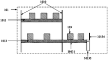
- the first end of the delivery transmission layer 1011 of the conveyor 101 is used to place the material 103, the first end of the delivery transmission layer 1012 is used to pick up the material 103, and the delivery transmission layer 1011 is used to transfer the material 103 from the delivery to the delivery.
- the first end of the layer 1011 is transported to the second end of the release transport layer 1011 , and the pickup transport layer 1012 is used to transport the material 103 from the second end of the pickup transport layer 1012 to the first end of the pickup transport layer 1012 .
- the above-mentioned conveyor 101 also includes a connecting device 1013 for transferring the material 103 from the second end of the delivery transport layer 1011 to the second end of the pickup transport layer 1012 .
- FIG. 5 exemplarily shows a top view of a connection device 1013 in the conveyor 101 provided by the embodiment of the present application
- FIGS. 6 and 7 exemplarily show the connection device 1013 corresponding to FIG. 5 in two connection states. side view.
- the above-mentioned connecting device 1013 includes: a third storage layer 10131, a transfer mechanism 10132 and a rotating fixing device 10133.
- the first end of the third storage layer 10131 is fixedly connected to the rotating fixing device 10133, and the third storage layer 10131
- the cargo layer 10131 moves between the second end of the delivery transport layer 1011 and the second end of the pickup transport layer 1012 ; the transfer mechanism 10132 is arranged on the third storage layer 10131 for transporting the material 103 .
- the second end of the third storage layer 10131 is connected to the second end of the delivery transmission layer 1011 .
- the second end of the third storage layer 10131 is connected to the delivery transmission layer 1012 the second end of the connection.
- the material 103 can be placed on the transfer mechanism 10132 to transfer the material 103 through the rotation of the transfer mechanism 10132 .
- the direction of rotation of the transfer mechanism 10132 can be changed.
- the rotation fixing device 10133 can be used to fix the first end of the third storage layer 10131 so that the first end cannot move, and the third storage layer 10131 can be around the rotation fixing device 10133 and perpendicular to the direction of the third storage layer 10131 rotate.
- the second end of the third storage layer 10131 will move along with it, so as to be between the second end of the pickup transport layer 1012 and the second end of the delivery transport layer 1011 switch. That is, the second end of the third storage layer 10131 can be docked with the second end of the pickup transport layer 1012 , and can also be switched to be connected to the second end of the delivery transport layer 1011 , and can also be switched to be connected to the pickup transport layer again.
- the second end of the transport layer 1012 is connected.
- a baffle 10134 may also be provided at the first end of the third storage layer 10131 .
- the third storage layer 10131 moves between the second end of the delivery transport layer 1011 and the second end of the pickup transport layer 1012 under the action of its own elastic force and the gravity of the material 103 thereon.
- the second end of the third storage layer 10131 is connected to the second end of the delivery transmission layer 1011 .
- the gravity of the material 103 lowers the second end of the third storage level 10131 to connect with the second end of the pickup transport level 1012.
- the second end of the third storage layer 10131 returns to the second end of the release transport layer 1011 again. so cycle.
- the embodiment of the present application can realize the movement of the second end of the third storage layer 10131 through its own elastic force and the gravity of the material 103 , avoid using other control structures or components, and help simplify the structure of the third storage layer 10131 .
- the above-mentioned connecting device 1013 includes, in addition to the third storage layer 10131, the transfer mechanism 10132 and the rotary fixing device 10133, a second controller and a material quantity detection device, which is used to detect The amount of materials on the third storage layer 10131, the second controller is used to control the second The end is connected to the second end of the pickup transmission layer 1012, or, when the material amount on the third storage layer 10131 is less than the preset material amount threshold, the second end of the third storage layer 10131 is controlled to be connected to the delivery transmission layer. The second end of 1011 is connected.
- the material amount may be the weight of the material 103 or the quantity of the material 103, and accordingly, the material amount detection device may be a pressure sensor or an image acquisition device.
- the pressure sensor can be arranged at the bottom of the third storage layer 10131 to detect the pressure of the material 103 on the third storage layer 10131 to the third storage layer 10131 , and the pressure is the weight of the material 103 .
- the image capturing device faces the third storage layer 10131 to capture the image of the material 103 on the third storage layer 10131 , and identify the quantity of the material 103 from the image of the material 103 .
- the above-mentioned material quantity detection device is electrically connected to the second controller, so as to send the material quantity to the second controller, and the second controller can control the movement of the third storage layer 10131 according to the material quantity.
- the material quantity detection device is an image acquisition device
- the image acquisition device can also send the image of the material 103 to the second controller, so that the second controller can recognize the quantity of the material 103 and control the third storage layer 10131 moves.
- the above-mentioned connecting device 1013 includes, in addition to the third storage layer 10131 , the transfer mechanism 10132 and the rotation fixing device 10133 , a second controller for controlling the second end of the third storage layer 10131 It is alternately connected with the second end of the pickup transport layer 1012 and the second end of the delivery transport layer 1011 in a preset time period, respectively.
- the preset time period may be determined according to the transmission speed of the delivery transmission layer 1012 and the delivery transmission layer 1011 .
- the preset time period can be set to be small; when the transmission speed is low, the preset time period can be set to be large.
- the transmission speed and the length of the third storage layer 10131 can also be determined.
- the transmission speed is fixed, if the length of the third storage layer 10131 is larger, the preset time period can be set larger, and if the length of the third storage layer 10131 is smaller, the preset time period can be set smaller.
- the functional relationship between the preset time period, the transmission speed, and the length of the third storage layer 10131 can be constructed based on experience.
- the functional relationship may be a linear function, which may be a linear function of the ratio of the length of the third storage layer 10131 to the transmission speed.
- the second end of the third storage layer 10131 may alternate with the second end of the pickup transport layer 1012 and the second end of the delivery transport layer 1011 respectively according to the preset time period connect.
- the preset time period is 1 minute
- the second end of the third storage layer 10131 may be connected to the second end of the pickup transport layer 1012 within the first minute
- the third storage layer may be connected within the second minute.
- the second end of the cargo layer 10131 is connected to the second end of the delivery transport layer 1011
- the second end of the third storage layer 10131 is connected to the second end of the take-out transport layer 1012 within the third minute, and the cycle is repeated.
- the transmission direction of the third storage layer 10131 is away from the pickup and transport. layer 1012 so that the material 103 is transferred from the pickup transfer layer 1012 to the third storage layer 10131 .
- the transmission direction of the third storage layer 10131 is toward the delivery transmission layer 1011, so that the material 103 can be transferred from the third storage layer to the delivery transmission layer 1011. 10131 is transmitted to the release transport layer 1011.
- the second controller can be electrically connected with the rotation fixing device 10133, so that the rotation fixing device 10133 rotates the third storage layer 10131, and the rotation direction and angle are preset of.
- FIG. 8 exemplarily shows a top view of another connection device 1013 in the conveyor 101 provided in the embodiment of the present application
- FIGS. 9 and 10 exemplarily show the connection device 1013 corresponding to FIG. 8 in two states. side view.
- the connecting device 1013 in FIGS. 8 to 10 is a lift.
- the elevator includes: four support frames 10136 , a fourth storage layer 10135 arranged on the support frames 10136 , and a transfer mechanism 10137 provided on the fourth storage layer 10135 , and the transfer mechanism 10137 can be rotated by rotating Material 103 is transported.
- the fourth storage layer 10135 can slide up and down along the support frame 10136 . In the process of sliding up and down, it can be docked with the second end of the delivery transmission layer 1011 or the second end of the delivery transmission layer 1012 .
- the second end of the fourth storage layer 10135 is butted with the second end of the pickup transport layer 1012
- the second end of the fourth storage layer 10135 is connected to the second end of the delivery transport layer 1011 . Two-end docking.
- the material 103 is obtained from the second end of the delivery transmission layer 1011, and then the elevator slides down to dock with the second end of the delivery transmission layer 1012, so as to Put the material 103 into the second end of the pick-up transmission layer 1012, and then the elevator slides up again to dock with the second end of the delivery transmission layer 1011 to obtain the material 103 from the second end of the delivery transmission layer 1011 again, so cycle.
- the delivery transport layer 1011 shown in FIG. 9 or FIG. 10 is located above the pickup transport layer 1012 . In practical applications, the delivery transport layer 1011 may also be located below the pickup transport layer 1012 .
- FIG. 11 exemplarily shows a flow chart of steps of a material conveying method provided by an embodiment of the present application.
- the method includes:
- S201 Control the pick-and-place device to move in a vertical direction to the delivery transport layer and the pick-up transport layer.
- the vertical direction includes the direction from the delivery transmission layer to the delivery transmission layer, and the direction from the delivery transmission layer to the delivery transmission layer.
- the pick-and-place device moves along a support rod where the pick-and-place device is located, and the support rod is perpendicular to the pick-up and delivery transport layer and the delivery transport layer. It can be seen that the vertical direction is the aforementioned first direction, and the vertical direction includes a first vertical direction and a second vertical direction. Since the delivery transport layer and the delivery transport layer are arranged in parallel up and down, the first vertical direction and the second vertical direction are upward and downward respectively.
- the pick-and-place device can be controlled to alternately move along the first vertical direction and the second vertical direction, and the moving along the first vertical direction includes: moving from the starting storage layer to the ending storage layer, moving along the second vertical direction Including: moving from the ending storage layer to the starting storage layer; in the initial state, the starting storage layer and the ending storage layer are respectively the uppermost layer and the lowermost layer in the at least two first storage layers; in which After the material is placed in the first storage layer of one layer, the starting storage layer and the ending storage layer are respectively updated to the uppermost and lowermost layers in the accessible storage layer, and there are materials to be picked up on the accessible storage layer.
- the first storage layer cannot place materials, nor can they take materials, so that the pick-and-place device can be controlled to no longer move to the first storage layer.
- materials are usually put into successive first storage layers, so that after each material is put into one of the first storage layers, the starting storage layer and the ending storage layer can be updated. cargo layer.
- the starting storage layer and the ending storage layer are respectively the highest layer and the lowest layer that can take and place materials in the first storage layer.
- the pick-and-place unit can be switched between up and down.
- a pick-and-place device can be cyclically moved as follows: move up a distance - move down a distance - ... - move up a distance.
- the idle storage layer is the first storage layer in an idle state, and the idle storage layer may be the first storage layer in which the material has not been placed, or the first storage layer in which the material has been taken away.
- control the pick-and-place device from the pick-and-place device when there is no material on the pick-and-place device, and there is at least one free storage layer in the at least two first storage layers, and there is material on the pick-and-place transport layer, control the pick-and-place device from the pick-and-place device. Pick up materials on the cargo transport layer.
- the delivery transport layer can transmit materials to the workstation, and the workstation is used to sort the materials, and the sorted materials are continued to be transported by the pickup transport layer.
- the material on the pickup and transport layer cannot be taken away in time, it will cause material accumulation on the pickup and transport layer. In this way, the sorted materials cannot continue to be transferred to the pickup transport layer, which affects the material sorting progress.
- the goods when there are materials on the pickup and transport layer, as long as there is no material on the pickup and release device and there is an idle storage layer in the first storage layer, the goods can be preferentially picked up from the pickup and transport layer. In this way, material accumulation on the pick-up transport layer can be avoided, thereby avoiding the impact on the material sorting progress.
- the amount of material on the pickup and delivery layer can be detected. If the material quantity exceeds the preset material quantity threshold, the pick-and-place device can be controlled to pick up materials from the pick-up transmission layer. If the material quantity does not exceed the preset material quantity threshold, the pick-and-place device can be controlled to pick up materials from the pick-up transmission layer or from the first storage layer.
- the pick-and-place device is controlled to pick up materials from a target material layer first reached in the moving process, where the target material layer is the first storage layer or the pick-up transmission layer.
- the pick-and-place device can be used to pick up materials when there is no material on the pick-and-place device. Specifically, materials can be taken from the first storage layer and placed on the delivery transport layer, or materials can be taken from the pickup transport layer and placed on the first storage layer. In the embodiment of the present application, in order to further shorten the moving distance of the pick-and-place device, the pick-and-place device can be controlled to pick up materials from the target material layer that arrives for the first time in the moving process.
- the pick-and-place device is controlled from the first storage layer that arrives for the first time during the movement process. Take material.
- the picking and placing device can be controlled to preferentially take materials from the first storage layer, and after picking up the materials, it will be judged whether the storage space of the delivery transmission layer is free. Put the fetched material on the delivery transmission layer. If there is material on the delivery position of the delivery transmission layer, it will be judged at a certain interval until the fetched material is placed on the delivery transmission layer.
- the pick-and-place device is controlled to put the materials into the delivery transport layer.
- the storage layer that the pick-and-place device reaches for the first time during the movement process is the accessible storage layer, and there are materials to be picked up on the accessible storage layer.
- the material to be picked up is the material that needs to be placed on the delivery transport layer, which needs to be distinguished from the material taken from the pickup transport layer, and the material taken from the pickup transport layer is put into the first storage. After the level, the material can no longer be taken out of the first storage level.
- a buffer rack is also provided beside the conveyor, and at least one second storage layer is arranged on the buffer rack, and the second storage layer is used to place the materials taken out from the pickup and transmission layer.
- the robot can use the pick-and-place device to pick up the materials from the pick-up transmission layer of the conveyor and put them on the second storage layer of the cache shelf.
- the material is placed in the first storage level.
- a transfer mechanism may also be provided on the second storage layer to transfer materials.
- the pick-and-place device can push the material onto the second storage layer or pull the material from the second storage layer, the second storage layer may not be provided with a transfer mechanism.
- the materials on the pickup transport layer can be placed on the cache rack, which helps to avoid the accumulation of materials on the pickup transport layer, thereby avoiding the impact on material sorting.
- the pickup and release device is controlled from The material is picked up on the pickup transport layer and placed in the free storage layer in the second storage layer.
- the pick-and-place device cannot put the materials on the pick-up transmission layer into the first storage layer.
- the robot can first pick up the material from the pickup transmission layer and put it into the idle storage layer in the second storage layer. After that, the robot can put the materials in the first storage layer into the delivery transmission layer. After there is a free storage layer in the first storage layer, the robot can take the materials from the pickup transmission layer and put them into the first storage layer. in the free storage floor.
- the material on the pickup transport layer can be detected. If the material on the pickup transport layer exceeds the preset material quantity threshold, and there is an idle storage deck in the second storage deck, the pickup and release device will be controlled to pick up the material from the pickup transport deck and put it into the second storage deck In the free storage layer in the layer. If the material on the pickup and transport layer does not exceed the preset material quantity threshold, the pickup and release device can be controlled to pick up the material from the pickup and transport layer and put it into the free storage layer in the second storage layer, or, Take the material from the first storage layer and put it into the release transport layer.
- control the pick-and-place device from The materials are taken from the second storage layer and put into the free storage layer in the first storage layer.
- the pickup and release device When there are materials on the pickup and transmission layer, and there are free storage layers in at least two first storage layers, the pickup and release device is controlled to take the materials from the pickup and transport layer, and put them into the first storage layer. in free storage.
- materials can be taken from the pickup and transport layer in advance, and only when there is no material on the pickup and transport layer, the materials are taken from the buffer storage layer. In this way, material accumulation on the pick-up transport layer can be avoided, thereby avoiding the impact on material sorting.
- a plurality of robots can be controlled to take materials from the second storage layer, and the robot has a preset amount in the first storage layer.
- free storage floor Ideally, all first storage levels of the robot are free storage levels.
- the embodiment of the present application further provides a unloading device, including: a robot, a conveyor and a controller, the robot includes at least one pick-and-place device and at least two layers of first storage layers, and the conveyor includes up and down parallel A delivery transmission layer and a delivery delivery layer are provided; wherein, the controller is used to control the movement of the delivery delivery device along the vertical direction of the delivery delivery layer and the delivery delivery layer, and, in the When there are materials obtained from the pickup and delivery layer on the pick-and-place device, the pick-and-place device is controlled to put the materials into the free storage layer first reached during the movement of the pick-and-place device.
- a unloading device including: a robot, a conveyor and a controller, the robot includes at least one pick-and-place device and at least two layers of first storage layers, and the conveyor includes up and down parallel A delivery transmission layer and a delivery delivery layer are provided; wherein, the controller is used to control the movement of the delivery delivery device along the vertical direction of the delivery delivery layer and the delivery delivery layer
- the above controller is also used for:
- the pick-and-place transport layer When there is no material on the pick-and-place device, there is at least one free storage layer in the at least two first storage layers, and there is material on the pick-and-place transport layer, control the pick and place The cargo device picks up the material from the pick-up transport layer.
- the above controller is also used for:
- the pick-and-place device When there is no material on the pick-and-place device, the pick-and-place device is controlled to pick up materials from the target material layer first reached in the moving process, and the target material layer is the first storage layer or the Pickup transport layer.
- the above-mentioned controller is further used for:
- control the first storage that the pick-and-place device first arrives in the moving process Take the material from the layer.
- the above controller is also used for:
- the pick-and-place device When there are materials obtained from the first storage layer on the pick-and-place device, the pick-and-place device is controlled to put the materials into the delivery transmission layer.
- the storage layer that the pick-and-place device reaches for the first time during the moving process is the accessible storage layer, and there are materials to be picked up on the accessible storage layer.
- the above controller is also used for:
- Controlling the pick-and-place device to alternately move along a first vertical direction and a second vertical direction includes: moving from a starting storage layer to an ending storage layer, the moving along the second vertical direction
- the moving includes: moving from the ending storage layer to the starting storage layer; in an initial state, the starting storage layer and the ending storage layer are respectively in at least two first storage layers the top and bottom layers;
- the starting storage layer and the ending storage layer are respectively updated to the uppermost layer and the lowermost layer in the accessible storage layers, and the There are items to be picked up on the pickup storage level.
- a cache shelf is also provided next to the conveyor, and at least one second storage layer is provided on the cache shelf, and the second storage layer is used for placing and taking out the goods from the pickup transmission layer. 's material.
- the above controller is also used for:
- control the pickup When there are materials on the pickup transmission layer, and there is no idle storage layer in the at least two first storage layers, and there is an idle storage layer in the second storage layer, control the pickup The delivery device picks up the material from the picking and transporting layer, and puts it into the free storage layer in the second storage layer.
- the above controller is also used for:
- control the pickup takes the material from the second storage layer and puts it into the free storage layer in the first storage layer.
- the above controller is also used for:
- the pickup and placement device is controlled to pick up the materials from the pickup and transport layer, and put them in into a free storage layer in the first storage layer.
- the unloading equipment provided in the embodiments of the present application is a device embodiment corresponding to the method embodiment, and has the same technical effect as the method embodiment. For detailed description, refer to the method embodiment, which will not be repeated here.
- Embodiments of the present application also provide a computer-readable storage medium, where computer-executable instructions are stored in the computer-readable storage medium, and when a processor executes the computer-executable instructions, a computing device is made to implement the aforementioned material conveying method.
- the embodiment of the present application also provides a computer program, and the computer program is used to implement the aforementioned material conveying method.
Landscapes
- Engineering & Computer Science (AREA)
- Mechanical Engineering (AREA)
- Warehouses Or Storage Devices (AREA)
- De-Stacking Of Articles (AREA)
Abstract
Description
Claims (14)
- 一种物料输送方法,其特征在于,应用于卸料设备,所述卸料设备包括:机器人和输送机,所述机器人包括至少一个取放货装置和至少两层第一储货层,所述输送机包括上下平行设置的放货传输层和取货传输层;所述方法包括:控制所述取放货装置沿与所述放货传输层和所述取货传输层的垂直方向移动;在所述取放货装置上存在从所述取货传输层上获取的物料时,控制所述取放货装置将所述物料放入所述取放货装置在移动过程中首次到达的空闲储货层。
- 根据权利要求1所述的方法,其特征在于,所述方法还包括:在所述取放货装置上不存在物料,且所述至少两层第一储货层中存在至少一层空闲储货层,且所述取货传输层上存在物料时,控制所述取放货装置从所述取货传输层上取物料。
- 根据权利要求1所述的方法,其特征在于,所述方法还包括:在所述取放货装置上不存在物料时,控制所述取放货装置从移动过程中首次到达的目标物料层上取物料,所述目标物料层为所述第一储货层或所述取货传输层。
- 根据权利要求3所述的方法,其特征在于,所述在所述取放货装置上不存在物料时,控制所述取放货装置从移动过程中首次到达的目标物料层上取物料,包括:在所述取放货装置上不存在物料,且所述至少两层第一储货层中不存在空闲储货层时,控制所述取放货装置从移动过程中首次到达的第一储货层中取所述物料。
- 根据权利要求1至4任一项所述的方法,其特征在于,所述方法还包括:在所述取放货装置上存在从所述第一储货层上获取的物料时,控制所述取放货装置将所述物料放入所述放货传输层。
- 根据权利要求3所述的方法,其特征在于,所述取放货装置在移动过程中首次到达的储货层为可取储货层,所述可取储货层上存在待取物料。
- 根据权利要求1所述的方法,其特征在于,所述控制所述取放货装置沿与所述放货传输层和所述取货传输层的垂直方向移动,包括:控制所述取放货装置沿第一垂直方向和第二垂直方向交替移动,所述沿第一垂直方向移动包括:从起始储货层移动至结束储货层,所述沿第二垂直方向移动包括:从所述结束储货层移动至所述起始储货层;在初始状态下,所述起始储货层和所述结束储货层分别为至少两层第一储货层中的最上层和最下层;在其中一层所述第一储货层被放置所述物料之后,将所述起始储货层和所述结束储货层分别更新为可取储货层中的最上层和最下层,所述可取储货层上存在待取物料。
- 根据权利要求1所述的方法,其特征在于,所述输送机旁边还设置有缓存货架,所述缓存货架上设置有至少一层第二储货层,所述第二储货层用于放置从所述取货传输层上取出的物料。
- 根据权利要求8所述的方法,其特征在于,所述方法还包括:在所述取货传输层上存在物料,且所述至少两层第一储货层中不存在空闲储货层,且所述第二储货层中存在空闲储货层时,控制所述取放货装置从所述取货传输层上取物料,并放入所述第二储货层中的空闲储货层中。
- 根据权利要求8所述的方法,其特征在于,所述方法还包括:在所述取货传输层上不存在物料,且所述至少两层第一储货层中存在空闲储货层,且至少一层所述第二储货层上存在物料时,控制所述取放货装置从所述第二储货层上取物料,并放入所述第一储货层中的空闲储货层中。
- 根据权利要求8所述的方法,其特征在于,所述方法还包括:在所述取货传输层上存在物料,且所述至少两层第一储货层中存在空闲储货层时,控制所述取放货装置从所述取货传输层上取物料,并放入所述第一储货层中的空闲储货层中。
- 一种卸料设备,其特征在于,包括:机器人、输送机和控制器,所述机器人包括至少一个取放货装置和至少两层第一储货层,所述输送机包括上下平行设置的放货传输层和取货传输层;其中,所述控制器用于控制所述取放货装置沿所述放货传输层和所述取货传输层的垂直方向移动,以及,在所述取放货装置上存在从所述取货传输 层上获取的物料时,控制所述取放货装置将所述物料放入所述取放货装置移动过程中首次到达的空闲储货层。
- 一种计算机可读存储介质,其特征在于,所述计算机可读存储介质中存储有计算机执行指令,当处理器执行所述计算机执行指令时,使计算设备实现如权利要求1至11任一项所述的方法。
- 一种计算机程序,其特征在于,所述计算机程序用于实现如权利要求1至11任一项所述的方法。
Priority Applications (3)
| Application Number | Priority Date | Filing Date | Title |
|---|---|---|---|
| JP2023560747A JP7642856B2 (ja) | 2021-03-31 | 2022-03-15 | 物品輸送方法および設備 |
| EP22778558.1A EP4299476A4 (en) | 2021-03-31 | 2022-03-15 | MATERIAL CONVEYING METHOD AND DEVICE |
| US18/475,897 US20240017942A1 (en) | 2021-03-31 | 2023-09-27 | Material conveying method and device |
Applications Claiming Priority (2)
| Application Number | Priority Date | Filing Date | Title |
|---|---|---|---|
| CN202110352761.3A CN113071840B (zh) | 2021-03-31 | 2021-03-31 | 物料输送方法及设备 |
| CN202110352761.3 | 2021-03-31 |
Related Child Applications (1)
| Application Number | Title | Priority Date | Filing Date |
|---|---|---|---|
| US18/475,897 Continuation US20240017942A1 (en) | 2021-03-31 | 2023-09-27 | Material conveying method and device |
Publications (1)
| Publication Number | Publication Date |
|---|---|
| WO2022206375A1 true WO2022206375A1 (zh) | 2022-10-06 |
Family
ID=76614521
Family Applications (1)
| Application Number | Title | Priority Date | Filing Date |
|---|---|---|---|
| PCT/CN2022/081006 Ceased WO2022206375A1 (zh) | 2021-03-31 | 2022-03-15 | 物料输送方法及设备 |
Country Status (6)
| Country | Link |
|---|---|
| US (1) | US20240017942A1 (zh) |
| EP (1) | EP4299476A4 (zh) |
| JP (1) | JP7642856B2 (zh) |
| CN (2) | CN113071840B (zh) |
| TW (1) | TWI844835B (zh) |
| WO (1) | WO2022206375A1 (zh) |
Cited By (1)
| Publication number | Priority date | Publication date | Assignee | Title |
|---|---|---|---|---|
| CN114671249A (zh) * | 2022-04-12 | 2022-06-28 | 安徽精菱玻璃机械有限公司 | 一种平板玻璃输送系统 |
Families Citing this family (1)
| Publication number | Priority date | Publication date | Assignee | Title |
|---|---|---|---|---|
| CN113071840B (zh) * | 2021-03-31 | 2023-10-31 | 深圳市库宝软件有限公司 | 物料输送方法及设备 |
Citations (11)
| Publication number | Priority date | Publication date | Assignee | Title |
|---|---|---|---|---|
| CN106927179A (zh) * | 2017-01-16 | 2017-07-07 | 黄金刚 | 一种智能仓储机器人、系统及控制方法、充电方法 |
| CN108313606A (zh) * | 2017-01-16 | 2018-07-24 | 浙江国自机器人技术有限公司 | 一种机器人搬运货物的方法 |
| CN109760984A (zh) * | 2019-03-19 | 2019-05-17 | 陈伦浩 | 一种有输送功能自动调整货位的立体货架 |
| CN110270973A (zh) * | 2018-12-29 | 2019-09-24 | 杭州慧盈智能科技有限公司 | 一种仓储物流机器人及其工作方法、自动更换电池方法 |
| CN111137610A (zh) * | 2019-12-26 | 2020-05-12 | 北京极智嘉科技有限公司 | 一种基于密集存储的货箱搬运方法及装置 |
| CN111620024A (zh) * | 2019-01-29 | 2020-09-04 | 北京极智嘉科技有限公司 | 一种搬运机器人、取货箱方法及放货箱方法 |
| CN111792260A (zh) * | 2020-07-24 | 2020-10-20 | 深圳市海柔创新科技有限公司 | 机器人、货物搬运方法、服务器以及仓储系统 |
| CN111977244A (zh) * | 2020-09-08 | 2020-11-24 | 北京极智嘉科技有限公司 | 一种仓库搬运调度系统及方法 |
| CN113071846A (zh) * | 2021-03-31 | 2021-07-06 | 深圳市海柔创新科技有限公司 | 物料输送方法及设备 |
| CN113071840A (zh) * | 2021-03-31 | 2021-07-06 | 深圳市库宝软件有限公司 | 物料输送方法及设备 |
| CN215045876U (zh) * | 2021-03-31 | 2021-12-07 | 深圳市海柔创新科技有限公司 | 卸料设备及输送机 |
Family Cites Families (24)
| Publication number | Priority date | Publication date | Assignee | Title |
|---|---|---|---|---|
| US4074120A (en) * | 1976-03-02 | 1978-02-14 | Kenway Incorporated | Automated materials storage system and method |
| JP2629048B2 (ja) * | 1989-06-09 | 1997-07-09 | 株式会社イトーキクレビオ | 自動倉庫システム |
| US8740538B2 (en) * | 2009-04-10 | 2014-06-03 | Symbotic, LLC | Storage and retrieval system |
| ATE543759T1 (de) * | 2009-11-27 | 2012-02-15 | Psb Intralogistics Gmbh | Kommissioniereinrichtung und verfahren zum kommissionieren |
| JP5516745B2 (ja) * | 2010-09-09 | 2014-06-11 | 村田機械株式会社 | 仕分システムと仕分方法 |
| WO2016210126A1 (en) | 2015-06-24 | 2016-12-29 | Hds Mercury, Inc. | Mobile robot loader-unloader system and method |
| CN106379681B (zh) * | 2016-07-11 | 2018-09-07 | 黄金刚 | 一种智能仓储机器人、系统及系统控制方法 |
| CN108363389A (zh) * | 2017-01-16 | 2018-08-03 | 浙江国自机器人技术有限公司 | 一种应用于移动机器人的超声波避障系统 |
| CN108750521A (zh) * | 2017-07-11 | 2018-11-06 | 浙江国自机器人技术有限公司 | 工作站台及订单完成系统 |
| JP6848081B2 (ja) | 2018-04-26 | 2021-03-24 | ベイジン ギークプラス テクノロジー カンパニー リミテッド | ロボット、搬送システムおよび方法 |
| CN109383974B (zh) * | 2018-09-10 | 2021-04-20 | 杭州慧盈智能科技有限公司 | 一种仓储机器人及其控制方法 |
| CN109018809B (zh) * | 2018-09-18 | 2020-09-11 | 惠科股份有限公司 | 一种仓储管理方法和仓储系统 |
| CN209536108U (zh) * | 2018-12-30 | 2019-10-25 | 江苏集萃智能制造技术研究所有限公司 | 一种立体仓库用半出库货物分拣设备 |
| US11119487B2 (en) * | 2018-12-31 | 2021-09-14 | Staples, Inc. | Automated preparation of deliveries in delivery vehicles using automated guided vehicles |
| CN110040412A (zh) * | 2019-04-24 | 2019-07-23 | 深圳市海柔创新科技有限公司 | 智能仓储系统、处理终端、仓储机器人及智能仓储方法 |
| CN210213640U (zh) * | 2019-05-16 | 2020-03-31 | 北京京东尚科信息技术有限公司 | 循环升降装置 |
| CN110443544A (zh) * | 2019-07-16 | 2019-11-12 | 格力电器(武汉)有限公司 | 仓储管理方法、装置、仓储柜和仓储系统 |
| CN112573058B (zh) * | 2019-09-30 | 2023-11-28 | 深圳市海柔创新科技有限公司 | 一种取货方法、搬运机器人、处理终端及智能仓储系统 |
| CN110789902B (zh) * | 2019-11-26 | 2025-04-18 | 新疆启盛物流科技有限公司 | 一种物流仓储中心及其智能转运站 |
| CN111169892B (zh) * | 2020-02-27 | 2022-01-04 | 成都三泰智能设备有限公司 | 一种互联互通自动存取系统及控制方法 |
| CN212355263U (zh) * | 2020-04-24 | 2021-01-15 | 深圳市鲸仓科技有限公司 | 立体仓储系统 |
| CN111874511A (zh) * | 2020-07-20 | 2020-11-03 | 南京音飞储存设备(集团)股份有限公司 | 一种带缓存位的存取货agv小车、货架组件及控制方法 |
| CN111891615A (zh) * | 2020-07-30 | 2020-11-06 | 深圳市海柔创新科技有限公司 | 转运装置、机器人、分拣系统及分拣方法 |
| CN212711037U (zh) * | 2020-07-30 | 2021-03-16 | 深圳市海柔创新科技有限公司 | 输送机 |
-
2021
- 2021-03-31 CN CN202110352761.3A patent/CN113071840B/zh active Active
- 2021-03-31 CN CN202311312518.4A patent/CN117184722B/zh active Active
-
2022
- 2022-03-15 EP EP22778558.1A patent/EP4299476A4/en active Pending
- 2022-03-15 WO PCT/CN2022/081006 patent/WO2022206375A1/zh not_active Ceased
- 2022-03-15 JP JP2023560747A patent/JP7642856B2/ja active Active
- 2022-03-30 TW TW111112160A patent/TWI844835B/zh active
-
2023
- 2023-09-27 US US18/475,897 patent/US20240017942A1/en active Pending
Patent Citations (11)
| Publication number | Priority date | Publication date | Assignee | Title |
|---|---|---|---|---|
| CN106927179A (zh) * | 2017-01-16 | 2017-07-07 | 黄金刚 | 一种智能仓储机器人、系统及控制方法、充电方法 |
| CN108313606A (zh) * | 2017-01-16 | 2018-07-24 | 浙江国自机器人技术有限公司 | 一种机器人搬运货物的方法 |
| CN110270973A (zh) * | 2018-12-29 | 2019-09-24 | 杭州慧盈智能科技有限公司 | 一种仓储物流机器人及其工作方法、自动更换电池方法 |
| CN111620024A (zh) * | 2019-01-29 | 2020-09-04 | 北京极智嘉科技有限公司 | 一种搬运机器人、取货箱方法及放货箱方法 |
| CN109760984A (zh) * | 2019-03-19 | 2019-05-17 | 陈伦浩 | 一种有输送功能自动调整货位的立体货架 |
| CN111137610A (zh) * | 2019-12-26 | 2020-05-12 | 北京极智嘉科技有限公司 | 一种基于密集存储的货箱搬运方法及装置 |
| CN111792260A (zh) * | 2020-07-24 | 2020-10-20 | 深圳市海柔创新科技有限公司 | 机器人、货物搬运方法、服务器以及仓储系统 |
| CN111977244A (zh) * | 2020-09-08 | 2020-11-24 | 北京极智嘉科技有限公司 | 一种仓库搬运调度系统及方法 |
| CN113071846A (zh) * | 2021-03-31 | 2021-07-06 | 深圳市海柔创新科技有限公司 | 物料输送方法及设备 |
| CN113071840A (zh) * | 2021-03-31 | 2021-07-06 | 深圳市库宝软件有限公司 | 物料输送方法及设备 |
| CN215045876U (zh) * | 2021-03-31 | 2021-12-07 | 深圳市海柔创新科技有限公司 | 卸料设备及输送机 |
Non-Patent Citations (1)
| Title |
|---|
| See also references of EP4299476A4 * |
Cited By (1)
| Publication number | Priority date | Publication date | Assignee | Title |
|---|---|---|---|---|
| CN114671249A (zh) * | 2022-04-12 | 2022-06-28 | 安徽精菱玻璃机械有限公司 | 一种平板玻璃输送系统 |
Also Published As
| Publication number | Publication date |
|---|---|
| TWI844835B (zh) | 2024-06-11 |
| CN117184722A (zh) | 2023-12-08 |
| TW202239686A (zh) | 2022-10-16 |
| US20240017942A1 (en) | 2024-01-18 |
| EP4299476A4 (en) | 2024-08-07 |
| CN113071840B (zh) | 2023-10-31 |
| JP7642856B2 (ja) | 2025-03-10 |
| CN113071840A (zh) | 2021-07-06 |
| EP4299476A1 (en) | 2024-01-03 |
| CN117184722B (zh) | 2026-01-23 |
| JP2024511548A (ja) | 2024-03-13 |
Similar Documents
| Publication | Publication Date | Title |
|---|---|---|
| WO2020216312A1 (zh) | 智能仓储系统、处理终端、仓储机器人及智能仓储方法 | |
| CN113135408B (zh) | 一种货箱转移系统、方法、货箱转移装置和机器人 | |
| CN218520353U (zh) | 仓储机器人 | |
| CN113511447B (zh) | 料箱处理系统、方法、设备、电子设备及存储介质 | |
| CN109969781A (zh) | 取出装置、传送装置、取出方法以及控制装置 | |
| WO2022206375A1 (zh) | 物料输送方法及设备 | |
| WO2025145769A1 (zh) | 仓储系统、仓库、仓储系统控制方法及存储介质 | |
| CN113071846B (zh) | 物料输送方法及设备 | |
| WO2025194868A1 (zh) | 一种堆叠料箱拣选系统、拣选机器人及方法 | |
| CN210735196U (zh) | 一种智能分拣货物的系统 | |
| CN118850606A (zh) | 订单处理方法、拣货工作站和仓储系统 | |
| CN215045876U (zh) | 卸料设备及输送机 | |
| JP7805754B2 (ja) | 移載装置、制御装置、移載方法、プログラム、及び記憶媒体 | |
| CN115258284A (zh) | 料箱处理方法、装置、机械臂、仓储系统及存储介质 | |
| CN218538025U (zh) | 装卸装置、货物装卸系统及分拣系统 | |
| CN216174411U (zh) | 货物输送系统 | |
| CN110481829A (zh) | 一种自动套箱生产线 | |
| CN215853255U (zh) | 物料箱转运系统 | |
| CN211469615U (zh) | 存锅系统 | |
| CN223097415U (zh) | 周转设备 | |
| CN116331704A (zh) | 一种中转装置及仓储系统 | |
| CN221190684U (zh) | 自动化码垛生产线 | |
| CN121376599A (zh) | 物品的转移方法、装置、电子设备和存储介质 | |
| HK40056894B (zh) | 一种货箱转移系统、方法、货箱转移装置和机器人 | |
| JP6275974B2 (ja) | 製品充填装置 |
Legal Events
| Date | Code | Title | Description |
|---|---|---|---|
| 121 | Ep: the epo has been informed by wipo that ep was designated in this application |
Ref document number: 22778558 Country of ref document: EP Kind code of ref document: A1 |
|
| WWE | Wipo information: entry into national phase |
Ref document number: 2022778558 Country of ref document: EP |
|
| WWE | Wipo information: entry into national phase |
Ref document number: 2023560747 Country of ref document: JP |
|
| ENP | Entry into the national phase |
Ref document number: 2022778558 Country of ref document: EP Effective date: 20230928 |
|
| NENP | Non-entry into the national phase |
Ref country code: DE |