WO2022206979A1 - 一种网络接入方法及装置 - Google Patents
一种网络接入方法及装置 Download PDFInfo
- Publication number
- WO2022206979A1 WO2022206979A1 PCT/CN2022/084931 CN2022084931W WO2022206979A1 WO 2022206979 A1 WO2022206979 A1 WO 2022206979A1 CN 2022084931 W CN2022084931 W CN 2022084931W WO 2022206979 A1 WO2022206979 A1 WO 2022206979A1
- Authority
- WO
- WIPO (PCT)
- Prior art keywords
- network element
- function network
- user plane
- upf
- home
- Prior art date
- Legal status (The legal status is an assumption and is not a legal conclusion. Google has not performed a legal analysis and makes no representation as to the accuracy of the status listed.)
- Ceased
Links
Images


Classifications
-
- H—ELECTRICITY
- H04—ELECTRIC COMMUNICATION TECHNIQUE
- H04W—WIRELESS COMMUNICATION NETWORKS
- H04W8/00—Network data management
- H04W8/02—Processing of mobility data, e.g. registration information at HLR [Home Location Register] or VLR [Visitor Location Register]; Transfer of mobility data, e.g. between HLR, VLR or external networks
- H04W8/08—Mobility data transfer
- H04W8/14—Mobility data transfer between corresponding nodes
-
- H—ELECTRICITY
- H04—ELECTRIC COMMUNICATION TECHNIQUE
- H04W—WIRELESS COMMUNICATION NETWORKS
- H04W48/00—Access restriction; Network selection; Access point selection
- H04W48/16—Discovering, processing access restriction or access information
-
- H—ELECTRICITY
- H04—ELECTRIC COMMUNICATION TECHNIQUE
- H04W—WIRELESS COMMUNICATION NETWORKS
- H04W76/00—Connection management
- H04W76/10—Connection setup
- H04W76/12—Setup of transport tunnels
-
- H—ELECTRICITY
- H04—ELECTRIC COMMUNICATION TECHNIQUE
- H04W—WIRELESS COMMUNICATION NETWORKS
- H04W8/00—Network data management
- H04W8/02—Processing of mobility data, e.g. registration information at HLR [Home Location Register] or VLR [Visitor Location Register]; Transfer of mobility data, e.g. between HLR, VLR or external networks
- H04W8/08—Mobility data transfer
- H04W8/12—Mobility data transfer between location registers or mobility servers
-
- H—ELECTRICITY
- H04—ELECTRIC COMMUNICATION TECHNIQUE
- H04W—WIRELESS COMMUNICATION NETWORKS
- H04W8/00—Network data management
- H04W8/26—Network addressing or numbering for mobility support
Definitions
- the present application relates to the field of wireless communication technologies, and in particular, to a network access method and device.
- the roaming scenarios defined in the existing 3rd generation partnership project (3GPP) network architecture are mainly aimed at international roaming scenarios.
- 3GPP 3rd generation partnership project
- MEC mobile edge computing
- the present application provides a network access method and device, which are used to enable a terminal device to access a local data network in a home location in a roaming scenario, thereby improving the security of the local data network in the home location, and at the same time satisfying the diverse needs of users.
- the service flow of the terminal equipment can be returned to the home location and distributed at the home location, or it can be distributed at the visited location according to preset distribution rules, so that a part of the service flow returns to the home location and the rest is unloaded at the visited location.
- an embodiment of the present application provides a network access method, which can be performed by a home session management function network element, or by a component (for example, a chip or a circuit) configured in the home session management function network element. .
- the method includes: inserting a home session management function network element into a home uplink classifier user plane function network element, and the uplink classifier user plane function network element is used to offload service flows of terminal equipment; when the terminal The device moves to the visited place, and the session management function network element sends the address of the user plane function network element of the uplink classifier to the intermediate user plane function network element of the visited place, so as to establish the connection between the intermediate user plane function network element and the A tunnel between upstream classifier user plane functional network elements.
- the above technical solution can establish a tunnel between the upstream classifier user plane function network element of the home and the intermediate user plane function network element of the visited place.
- the service flow of the terminal device can be returned through the tunnel.
- inserting the home session management function network element into the home uplink classifier user plane function network element includes: the home session management function network element according to the The data network name DNN subscribed by the terminal equipment is inserted into the user plane function network element of the uplink classifier.
- inserting the home session management function network element into the home uplink classifier user plane function network element includes: the session management function network element receives data from the policy control function network element.
- the user policy of the terminal device of the element the user policy is used to indicate that in the roaming scenario, the service flow of the terminal device needs to be returned to the home and offloaded; the session management function network element, according to the user policy, inserts The uplink classifier user plane functional network element.
- the session management function network element at the home location can insert the uplink classifier user plane function network element in the home location when the service flow of the terminal device needs to be returned to the home location and offloaded in the roaming scenario indicated by the user policy of the terminal device. , so as to meet the requirement of returning the full-service traffic of the terminal equipment to the home area and shunting it, and improve the security of the local data network in the home area.
- the method further includes: the session management function network element sends a first offload rule to the uplink classifier user plane function network element, where the first offload rule is used for Instructing to send the service flow matching the first offloading rule to the secondary anchor user plane functional network element of the home, and the secondary anchor user plane functional network element is connected to the local data network of the home.
- the method further includes: the session management function network element sending the address of the uplink classifier user plane function network element to the secondary anchor user plane function network element, to establish a tunnel between the secondary anchor user plane function network element and the uplink classifier user plane function network element.
- the first offload rule is further used to instruct to send a service flow that does not match the first offload rule to the home primary anchor user plane function network element, the The primary anchor user plane functional network element connects to the Internet.
- the method further includes: the session management function network element sending the address of the uplink classifier user plane function network element to the primary anchor user plane function network element, to establish a tunnel between the primary anchor user plane function network element and the uplink classifier user plane function network element.
- the method further includes: the session management function network element sends the address of the uplink classifier user plane function network element to the home access network device, so as to establish the A tunnel between the access network device and the uplink classifier user plane function network element.
- the user plane function network element of the uplink classifier at the home can be distributed in a forward distribution manner, and the service flow matching the first distribution rule is distributed to the auxiliary anchor point user plane function network element, so that the terminal equipment can be distributed. Access the local data network of the home location, and distribute the service flow that does not match the first distribution rule to the main anchor user plane functional network element, so that the terminal device can access the Internet.
- the session management function network element of the home place can also update the main anchor point user plane function network element and the auxiliary anchor point user plane function network element of the home place respectively. and the bearer rules of the access network equipment, so as to open up the transmission path of the upstream and downstream service flows of the terminal equipment.
- the method further includes: inserting the session management function network element into the visited place the intermediate user plane function network element located at the location; the session management function network element sends the address of the intermediate user plane function network element to the uplink classifier user plane function network element to establish the uplink classifier user plane A tunnel between the functional network element and the intermediate user plane functional network element.
- the method further includes: the session management function network element sends the address of the intermediate user plane function network element to the access network device in the visited place, so as to establish the connection A tunnel between the network access device and the intermediate user plane functional network element.
- the session management function network element sends a message to the intermediate user plane function network of the visited place. sending the address of the user plane function network element of the uplink classifier, including: the session management function network element sending the uplink classifier to the intermediate user plane function network element through the intermediate session management function network element of the visited place The address of the user plane function NE.
- the method further includes: the session management function network element receives the intermediate user from the intermediate user plane function network element through the intermediate session management function network element The address of the network element of the function of the plane function; the network element of the session management function sends the address of the function network element of the intermediate user plane to the network element of the user plane function of the uplink classifier, so as to establish the network element of the user plane function of the uplink classifier and the network element of the user plane of the uplink classifier.
- the tunnel between the intermediate user plane functional network elements receives the intermediate user from the intermediate user plane function network element through the intermediate session management function network element The address of the network element of the function of the plane function; the network element of the session management function sends the address of the function network element of the intermediate user plane to the network element of the user plane function of the uplink classifier, so as to establish the network element of the user plane function of the uplink classifier and the network element of the user plane of the uplink classifier.
- the above technical solution can be applied to two situations where the terminal equipment is still in the service area of the session management function network element in the home place after moving to the visited place, and when the terminal equipment moves to the visited place and leaves the service area of the session management function network element in the home place. a roaming scene.
- the session management function network element of the home place can be inserted into the intermediate user plane function network element of the visited place, that is, the home
- the local session management function network element is also the visited local session management function network element.
- an embodiment of the present application provides a network access method.
- the method can be executed by an intermediate session management function network element in the visited place, or by a component (for example, a chip or a circuit) configured in the intermediate session management function network element in the visited place. )implement.
- the method includes: when the terminal device moves to the visited place, the intermediate session management function network element of the visited place is inserted into the intermediate user plane function network element of the visited place; the intermediate session management function network element receives the session management function network element from the home place.
- the address of the user plane function network element of the uplink classifier, the user plane function network element of the uplink classifier is used to offload the service flow of the terminal equipment, and the address of the user plane function network element of the uplink classifier is used to establish the A tunnel between an intermediate user plane functional network element and the uplink classifier user plane functional network element.
- the above technical solution can establish a tunnel between the upstream classifier user plane function network element of the home and the intermediate user plane function network element of the visited place.
- the service flow of the terminal device can be returned through the tunnel.
- the home location, and the offload is performed under the action of the user plane function network element of the uplink classifier at the home location.
- the above technical solution can be applied to the roaming scenario where the terminal equipment moves to the visited place and leaves the service area of the session management function network element of the home place.
- the intermediate session management function network element of the visited place can be inserted into the middle of the visited place.
- User plane functional network element
- the method further includes: the intermediate session management function network element sending the address of the uplink classifier user plane function network element to the intermediate user plane function network element, to A tunnel is established between the intermediate user plane functional network element and the uplink classifier user plane functional network element.
- the method further includes: the intermediate session management function network element sends the address of the intermediate user plane function network element to the session management function network element, so as to establish the A tunnel between the upstream classifier user plane functional network element and the intermediate user plane functional network element.
- the method further includes: the intermediate session management function network element sends the address of the intermediate user plane function network element to the access network device in the visited place, so as to establish the A tunnel between an access network device and the intermediate user plane functional network element.
- the session management function network element of the visited place can also update the bearer rules of the intermediate user plane function network element of the visited place and the access network device respectively, thereby getting through.
- the transmission path of the upstream and downstream service flows of the terminal device.
- an embodiment of the present application provides a network access method.
- the method can be executed by a session management function network element in a visited place, or by a component (such as a chip or a circuit) configured in the session management function network element at the visited place. .
- the method includes: when the terminal device moves to the visited place, the session management function network element of the visited place is inserted into the uplink classifier user plane function network element of the visited place, and the uplink classifier user plane function network element is used for the terminal device.
- the service flow is distributed; the session management function network element of the visited place sends a second distribution rule to the user plane function network element of the uplink classifier, and the second distribution rule is used to indicate the matching of the second distribution rule.
- the service flow is sent to the main anchor user plane functional network element of the home location, and the main anchor user plane functional network element is connected to the local data network of the home location.
- the service flow of the terminal device can pass through the upstream classifier.
- the user plane function network elements are offloaded to the main anchor point user plane function network elements in the home area, so as to meet the requirement of returning some service flows of the terminal equipment to the home area.
- the session management function network element of the visited place is inserted into the uplink classifier user plane function network element of the visited place, including: the session management function network element of the visited place is based on the The data network name DNN subscribed by the terminal equipment is inserted into the user plane function network element of the uplink classifier.
- the session management function network element of the visited place is inserted into the uplink classifier user plane function network element of the visited place, including: the session management function network element of the visited place is based on the The user policy of the terminal device, which is inserted into the user plane function network element of the uplink classifier, and the user policy is used to indicate that in the roaming scenario, the service flow of the terminal device needs to be offloaded at the visited place and access the local data of the home place The business flow of the network returns to the homeland.
- the session management function network element of the visited place can be shunted in the visited place when the user policy of the terminal device indicates that the service flow of the terminal device needs to be offloaded in the visited place, and when the service flow of the local data network of the home place returns to the home place. , and insert the upstream classifier user plane functional network element in the visited place, so as to meet the requirement that part of the service traffic of the terminal equipment that meets the rules returns to the home place, and the rest of the traffic is unloaded locally in the visited place.
- the service flow that does not match the second distribution rule can be unloaded locally in the visited place, it is not necessary to send all the service flows of the terminal device back to the home place. Therefore, the above technical solution can make full use of network resources and reduce user access. Internet latency.
- the method further includes: the session management function network element of the visited place sending the address of the user plane function network element of the uplink classifier to the main anchor point user plane function network element, so as to establish a relationship between the main anchor point user plane function network element and the uplink classifier user plane function network element tunnel.
- the method further includes: the session management function network element of the visited place Send the address of the uplink classifier user plane function network element to the main anchor point user plane function network element through the home session management function network element, so as to establish the main anchor point user plane function network element and the main anchor point user plane function network element.
- the session management function network element of the visited place Send the address of the uplink classifier user plane function network element to the main anchor point user plane function network element through the home session management function network element, so as to establish the main anchor point user plane function network element and the main anchor point user plane function network element.
- a tunnel between the upstream classifier user plane functional network elements if the session management function network element of the visited place is different from the session management function network element of the home place, the method further includes: the session management function network element of the visited place Send the address of the uplink classifier user plane function network element to the main anchor point user plane function network element through the home session management function network element, so as to establish the main anchor point user plane function network element and the main anchor point user plane function network element.
- the second offloading rule is used to indicate that a service flow that does not match the second offloading rule is sent to the secondary anchor point user plane function network element of the visited place, and the secondary anchor Click the user plane function NE to connect to the Internet.
- the upstream classifier user plane function network element of the visited place can be distributed in a reverse flow mode, and the service flow matching the second distribution rule is distributed to the main anchor point user plane function network element, so that the terminal device can be used. Access the local data network of the home location, and offload the service flow that does not match the second offloading rule to the user plane function network element of the secondary anchor point, so that the terminal device can access the Internet.
- the method further includes: the session management function network element of the visited place sends the uplink classifier user plane function network element to the secondary anchor user plane function network element address to establish a tunnel between the secondary anchor user plane function network element and the uplink classifier user plane function network element.
- the method further includes: the session management function network element of the visited place sends the address of the uplink classifier user plane function network element to the access network device of the visited place, to establish a tunnel between the access network device and the uplink classifier user plane functional network element.
- an embodiment of the present application provides a communication device.
- the communication device may have the function of implementing the session management function network element at home in any of the above aspects or any possible design of the various aspects, or have the function of implementing the above-mentioned various aspects.
- the apparatus may be a network device or a chip included in the network device.
- the functions of the above communication apparatus may be implemented by hardware, or by executing corresponding software in hardware, and the hardware or software includes one or more modules or units or means corresponding to the above functions.
- the structure of the communication device includes a processing module and a transceiver module, wherein the processing module is configured to support the communication device to perform the first session management function in any design of the above aspects or aspects.
- the corresponding function of the network element, or the corresponding function of the network element to perform the session management function of the home in any of the above aspects or any design of the various aspects, or to perform the above aspects or any design of the various aspects.
- the transceiver module is used to support the communication between the communication device and other communication devices.
- the communication device when the communication device is the session management function network element of the home place, it can send the uplink classifier user plane function network element to the intermediate user plane function network element of the visited place.
- the address of the network element may also include a storage module, which is coupled to the processing module and stores necessary program instructions and data of the device.
- the processing module may be a processor
- the communication module may be a transceiver
- the storage module may be a memory
- the memory may be integrated with the processor, or may be provided separately from the processor.
- the structure of the communication device includes a processor, and may also include a memory.
- the processor is coupled to the memory and operable to execute computer program instructions stored in the memory to cause an apparatus to perform the methods in the aspects described above or in any possible design of the aspects.
- the communication device further includes a communication interface, and the processor is coupled to the communication interface.
- the communication interface may be a transceiver or an input/output interface; when the device is a chip included in the network device, the communication interface may be an input/output interface of the chip.
- the transceiver may be a transceiver circuit, and the input/output interface may be an input/output circuit.
- an embodiment of the present application provides a chip system, including: a processor, where the processor is coupled to a memory, and the memory is used to store a program or an instruction, and when the program or instruction is executed by the processor , so that the system-on-a-chip implements the above aspects or any method in any possible design of the various aspects.
- the chip system further includes an interface circuit, and the interface circuit is used to exchange code instructions to the processor.
- processors in the chip system, and the processors may be implemented by hardware or software.
- the processor may be a logic circuit, an integrated circuit, or the like.
- the processor may be a general-purpose processor implemented by reading software codes stored in memory.
- the memory can be integrated with the processor or separate from the processor.
- the memory may be a non-transitory processor, such as a read-only memory, which may be integrated with the processor on the same chip, or may be provided on different chips.
- an embodiment of the present application provides a communication system, where the communication system includes a home session management function network element and/or an intermediate session management function network element at a visited place; wherein the home session management function network element
- the element is used to implement the first aspect or the method in any possible design of the first aspect
- the intermediate session management function network element of the visited place is used to implement the second aspect or any possibility of the second aspect. method in the design.
- the communication system further includes a home uplink classifier user plane function network element, a primary anchor point user plane function network element, a secondary anchor point user plane function network element, and an intermediate user plane function network element at the visited place.
- an embodiment of the present application provides a communication system, where the communication system includes a session management function network element of a visited place; wherein the session management function network element of the visited place is used to implement the above third aspect or the third aspect method in any of the possible designs.
- the communication system further includes an uplink classifier user plane function network element and a secondary anchor point user plane function network element at the visited place, and a primary anchor point user plane function network element at the home place.
- an embodiment of the present application provides a computer-readable storage medium on which a computer program or instruction is stored, and when the computer program or instruction is executed, enables the computer to execute the above aspects or any of the various aspects. method in the design.
- the embodiments of the present application provide a computer program product, which, when a computer reads and executes the computer program product, causes the computer to execute the above aspects or the methods in any possible designs of the various aspects.
- the present application provides a method and device for accessing a campus network, so that when a user roams between provinces or between cities within a province, he or she can also access the home campus network, thereby improving the security of the campus network.
- the user's service flow can be distributed after returning to the home area, or based on the distribution strategy, part of it is unloaded at the visited place, and part of it is returned to the home area, so as to meet the diverse business needs of the campus network.
- the present application provides a method for accessing a campus network, the method comprising:
- the session management function SMF of the home place inserts the uplink classifier user plane function ULCL UPF in the home place according to the subscription data and the current location of the terminal device; the SMF of the home place determines the service flow of the terminal device in the roaming scenario. Return to the home and perform traffic distribution; the SMF of the home sends the address of the ULCL UPF, and the address of the ULCL UPF is used for the forwarding user plane function I-UPF of the visited place to forward the ULCL UPF to the ULCL UPF. End-device traffic flow.
- the method further includes:
- the home SMF receives the address of the I-UPF from the visited forwarding session management function I-SMF;
- the home SMF sends the address of the I-UPF to the ULCL UPF, where the address of the I-UPF is used by the ULCL UPF to forward the service flow of the terminal device to the I-UPF.
- the method further includes:
- the home SMF sends the address of the ULCL UPF to the visited SMF.
- the method further includes:
- the SMF at the home site inserts the I-UPF at the visited site.
- the method further includes:
- the SMF of the home place sends the address of the ULCL UPF to the I-UPF of the visited place;
- the home SMF sends the address of the I-UPF to the ULCL UPF, where the address of the I-UPF is used by the ULCL UPF to forward the service flow of the terminal device to the I-UPF.
- the present application provides a method for accessing a campus network, the method comprising:
- the session management function SMF of the visited place inserts the uplink classifier user plane function ULCL UPF in the visited place according to the subscription data and the current location of the terminal device; the SMF of the visited place sends the offloading rule to the ULCL UPF, and the offloading
- the rule includes sending the service flow matching the first address to the UPF of the home place, and sending the service flow matching the second address to the UPF of the visited place, wherein the service flow matching the first address is used to visit the home the local network of the locality, and the traffic matching the second address is used to access the Internet.
- the second address is an address other than the first address.
- FIG. 1 is a schematic diagram of a network architecture in a roaming scenario to which this application is applicable;
- FIG. 2 is a schematic diagram of an intra-provincial roaming scenario in Embodiment 1 of the present application.
- FIG. 3 is a schematic diagram of an inter-provincial roaming scenario in Embodiment 1 of the present application.
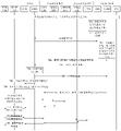
- FIG. 4 is a schematic flowchart of a network access method according to Embodiment 1 of the present application.
- FIG. 5 is a related process corresponding to the network access method in Embodiment 1 of the present application when the terminal device is located at the home;
- FIG. 6 is a related process corresponding to the network access method in Embodiment 1 of the present application when a terminal device is located in a visited place in a roaming scenario within a province;
- FIG. 7 is a related process corresponding to the network access method in Embodiment 1 of the present application when a terminal device is located in a visited place in an inter-provincial roaming scenario;
- Embodiment 8a and 8b are a specific example of Embodiment 1 of the present application.
- FIG. 9 is a schematic diagram of an intra-provincial roaming scenario in Embodiment 2 of the present application.
- FIG. 10 is a schematic diagram of an inter-provincial roaming scenario in Embodiment 2 of the application.
- FIG. 11 is a schematic flowchart of a network access method according to Embodiment 2 of the present application.
- FIG. 12 is a related process corresponding to the network access method in Embodiment 2 of the present application when the terminal device is located in the visited place in the scenario of intra-provincial roaming;
- FIG. 13 is a related process corresponding to the network access method in the second embodiment of the application when the terminal device is located in the visited place in the inter-provincial roaming scenario;
- FIG. 14 is a specific example of Embodiment 2 of the application.
- FIG. 15 is a schematic diagram of an intra-provincial roaming scenario when a unified UPF is adopted in Embodiment 2 of the application;
- FIG. 16 is a schematic diagram of an inter-provincial roaming scenario when a unified UPF is adopted in Embodiment 2 of the present application;
- FIG. 17 and FIG. 18 are schematic structural diagrams of a communication device provided by the present application.
- Figure 19 is a network architecture of a 5G network suitable for roaming scenarios defined by the current 3GPP standard
- FIG. 20 is a schematic diagram of a campus access scenario in Embodiment 3 of the present application.
- FIG. 21 is a schematic diagram of an intra-provincial roaming scenario in Embodiment 3 of the application.
- FIG. 22 is a schematic diagram of an inter-provincial roaming scenario in Embodiment 3 of the present application.
- FIG. 23 is a schematic diagram of a network architecture to which Embodiment 3 of the present application is applicable;
- FIG. 24 is a schematic diagram of a business process in Embodiment 3 of the application.
- FIG. 25 is a schematic diagram of a campus access scenario in Embodiment 4 of the present application.
- 26 is a schematic diagram of an intra-provincial roaming scenario in Embodiment 4 of the present application.
- FIG. 27 is a schematic diagram of an inter-provincial roaming scenario in Embodiment 4 of the present application.
- FIG. 28 is a schematic diagram of a network architecture to which Embodiment 4 of the present application is applicable.
- FIG. 29 is a schematic diagram of a business process in Embodiment 4 of the application.
- FIG. 30 is a schematic diagram of a network architecture to which Embodiment 5 of the present application is applicable.
- LTE long term evolution
- FDD frequency division duplex
- TDD time division duplex
- 5G fifth generation mobile communication systems or new radio (NR) systems
- NR new radio
- this application takes the 5G network architecture related to roaming scenarios defined in the 3GPP standard as an example to introduce the network architecture in the roaming scenario applicable to this application.
- the network architecture includes three parts, namely terminal equipment, data network (DN) and operator network.
- the operator network may include but not limited to one or more of the following network elements or functional entities: access and mobility management function (access and mobility management function, AMF) network element, session management function (session management function, SMF) network element, intermediate SMF (intermediate SMF, I-SMF) network element, user plane function (user plane function, UPF) network element, intermediate UPF (intermediate UPF, I-UPF) network element, uplink classifier UPF (uplink) classifier, ULCL UPF) network element, protocol data unit (protocol data unit, PDU) session anchor UPF (PDU session anchor UPF, PSA UPF) network element and radio access network (radio access network, RAN) equipment.
- access and mobility management function access and mobility management function, AMF
- SMF session management function
- I-SMF intermediate SMF
- UPF user plane function
- UPF intermediate UPF
- I-UPF uplink classifier
- ULCL UPF uplink classifier
- ULCL UPF protocol data unit
- the network architecture may further include a policy control function (PCF) network element, a unified data management (unified data management, UDM) network element, a unified data repository (unified data repository, UDR) network element, Network elements or functional entities such as an application function (application function, AF) network element are not shown in FIG. 1 for the time being.
- PCF policy control function
- UDM unified data management
- UDR unified data repository
- AF application function
- the terminal device in this embodiment of the present application may be a device for implementing a wireless communication function.
- the terminal equipment may be a user equipment (UE), an access terminal, a terminal unit, a terminal station, a mobile station, a mobile station in a 5G network or a public land mobile network (PLMN) evolved in the future.
- UE user equipment
- PLMN public land mobile network
- remote station remote terminal
- mobile device wireless communication device
- terminal agent or terminal device etc.
- the access terminal may be a cellular phone, a cordless phone, a session initiation protocol (SIP) phone, a wireless local loop (WLL) station, a personal digital assistant (PDA), a wireless communication Functional handheld devices, computing devices or other processing devices connected to wireless modems, in-vehicle devices or wearable devices, virtual reality (VR) end devices, augmented reality (AR) end devices, industrial control (industrial) wireless terminal in control), wireless terminal in self-driving, wireless terminal in remote medical, wireless terminal in smart grid, wireless terminal in transportation safety Terminals, wireless terminals in smart cities, wireless terminals in smart homes, etc.
- the terminal device may be mobile or fixed, which is not limited.
- the above-mentioned terminal equipment can establish a connection with the operator network through an interface (eg, N1 interface, etc.) provided by the operator network, and use services such as data and/or voice provided by the operator network.
- the terminal device can also access the DN through the operator's network, and use the operator's service deployed on the DN and/or the service provided by a third party.
- the above-mentioned third party may be a service party other than the operator's network and the terminal device, and may provide other data and/or voice services for the terminal device.
- the specific form of the above-mentioned third party can be determined according to the actual application scenario, which is not limited here.
- RAN is a sub-network of an operator's network, and is an implementation system between service nodes and terminal equipment in the operator's network.
- the terminal device To access the operator's network, the terminal device first passes through the RAN, and then can be connected to the service node of the operator's network through the RAN.
- the RAN device in this application is a device that provides a wireless communication function for a terminal device, and the RAN device is also called an access network device.
- the RAN equipment in this application includes but is not limited to: next-generation base station (g nodeB, gNB), evolved node B (evolved node B, eNB), radio network controller (radio network controller, RNC), node B in 5G (node B, NB), base station controller (BSC), base transceiver station (base transceiver station, BTS), home base station (for example, home evolved nodeB, or home node B, HNB), baseband unit (baseBand unit, BBU), transmission point (transmitting and receiving point, TRP), transmitting point (transmitting point, TP), mobile switching center, etc.
- next-generation base station g nodeB, gNB
- evolved node B evolved node B
- eNB evolved node B
- RNC radio network controller
- node B in 5G node B, NB
- base station controller BSC
- base transceiver station base transceiver station
- BTS home base station
- base station for example, home
- the AMF network element is mainly responsible for mobility management, access authentication/authorization and other functions, such as terminal device registration, location update, and mobility state switching. In addition, it is also responsible for transferring user policies between the end device and the PCF.
- the SMF network element is mainly responsible for session management, execution of control policies issued by PCF, selection of UPF, and allocation of UE network protocol (IP) addresses.
- the home SMF network element may also be referred to as an anchor SMF (anchor SMF, A-SMF) network element of the terminal device.
- the I-SMF network element also called the forwarding SMF network element, is used to forward control plane messages between the visited location and the home location.
- the AMF network element can be inserted into the I-SMF network element in the visited place.
- the UPF network element as the interface UPF with the data network, is mainly responsible for functions such as user plane data forwarding, session/flow-level accounting statistics, and bandwidth limitation.
- the PSA UPF network element also known as the anchor UPF network element, serves as the anchor point for connecting with the PDU session, and is responsible for filtering, forwarding, rate control, and charging of the user plane data of the terminal device.
- the home PSA UPF network element is called the main PSA UPF network element of the terminal device (that is, the main anchor UPF network element).
- the present application supports inserting one or more secondary PSA UPF network elements (ie, secondary anchor UPF network elements) on the user plane path of the PDU session of the terminal device, so that the terminal device can access the local data network nearby.
- the secondary PSA UPF network element can be deployed in the home place (for example, the edge area of the home place), or can be deployed in the visited place, which is not limited.
- the main PSA UPF network element (or the main anchor UPF network element) refers to the UPF network element connected to the terminal device when it is initially activated to create a session, and is used for allocating an IP address to the terminal device and forwarding user plane data.
- the secondary PSA UPF network element (or secondary anchor UPF network element) refers to the UPF network element inserted after the session of the terminal device is created, and is used to forward user plane data for the terminal device.
- the I-UPF network element also known as the forwarding UPF network element, is used to forward user plane data between the visited location and the home location.
- the A-SMF network element (the location of the corresponding terminal device is still in the A-SMF network element)
- the situation in the service area of the A-SMF network element) or the I-SMF network element (corresponding to the situation that the location of the terminal equipment is no longer in the service area of the A-SMF network element or the situation that there is an I-SMF network element) can insert the I-SMF network element in the visited place.
- UPF network element UPF network element.
- the I-UPF network element can be deployed together with the ULCL UPF network element, such as the ULCL UPF+I-UPF network element in Figure 1, which means that the network element can act as an I-UPF network element at the same time to realize the N3 interface capability in the roaming scenario .
- ULCL UPF network element is a working form of UPF network element. It is used for service offloading and can determine the direction of data flow according to different destination addresses accessed by users.
- the ULCL UPF network element can be inserted at the home location or inserted at the visited location, which is not limited.
- ULCL UPF network elements can also be deployed together with other UPF network elements (such as I-UPF network elements or PSA UPF network elements). network element to implement the offload function.
- the PCF network element is mainly responsible for policy control functions such as charging for sessions and service flow levels, QoS (quality of service) bandwidth guarantee, mobility management, and UE policy decision-making.
- policy control functions such as charging for sessions and service flow levels, QoS (quality of service) bandwidth guarantee, mobility management, and UE policy decision-making.
- the UDM network element is mainly responsible for the management of contract data, user access authorization and other functions.
- the UDR network element is mainly responsible for the access function of data such as subscription data, policy data, and application data.
- the AF network element is mainly responsible for delivering the requirements of the application side to the network side, such as QoS requirements or subscription of user status events.
- the AF can be a third-party functional entity or an application service deployed by an operator.
- the AF network element may also be called an application server, or a third-party device.
- the DN is a data network that provides business services for users.
- the client is located in the terminal device, and the server is located in the data network.
- the data network can be a private network, such as a local area network, or an external network that is not controlled by an operator, such as the Internet, or a private network jointly deployed by operators, such as a configured IP multimedia network subsystem (IP multimedia core network subsystem, IMS) service.
- IP multimedia core network subsystem, IMS IP multimedia core network subsystem
- the local data network deployed at the home location may be different from the local data network deployed at the visited location.
- the local data network deployed at home in this application may also be referred to as a campus network, an enterprise network, an enterprise private network, a local network, etc., without limitation.
- the N1 interface refers to the interface between the AMF and the UE, and is used to transmit QoS control rules and the like to the UE.
- the N2 interface refers to the interface between the AMF and the RAN, and is used to transmit radio bearer control information from the core network side to the RAN.
- the N3 interface refers to the interface between the (R)AN and the UPF, and is used for transferring user plane data between the (R)AN and the UPF.
- the N4 interface refers to the interface between the SMF and the UPF, which is used to transmit information between the control plane and the user plane, including controlling the distribution of forwarding rules, QoS control rules, traffic statistics rules, etc. information reporting.
- the N5 interface refers to the interface between the AF and the PCF, which is used for application service request delivery and network event reporting. This interface is not shown in Figure 1 for the time being.
- the N6 interface refers to the interface between the UPF and the DN, and is used to transfer user plane data between the UPF and the DN.
- the N7 interface refers to the interface between the PCF and the SMF, and is used to deliver control policies for PDU session granularity and service data flow granularity. This interface is not shown in Figure 1 for the time being.
- the N8 interface refers to the interface between the AMF and the UDM, which is used by the AMF to obtain the subscription data and authentication data related to access and mobility management from the UDM, and to register the UE's current mobility management related information with the UDM. This interface is not shown in Figure 1 for the time being.
- the N9 interface refers to the interface between the UPF and the UPF, such as the interface between the UPF connected to the DN and the UPF connected to the (R)AN, and is used to transfer user plane data between the UPFs.
- the N10 interface refers to the interface between the SMF and the UDM, and is used for the SMF to obtain the subscription data related to session management from the UDM, and the SMF to register the UE's current session related information to the UDM. This interface is not shown in Figure 1 for the time being.
- the N11 interface refers to the interface between the SMF and the AMF, and is used to transfer the PDU session tunnel information between the RAN and the UPF, the control messages sent to the UE, and the radio resource control information sent to the RAN.
- the N15 interface refers to the interface between the PCF and the AMF, and is used to deliver UE policies and access control related policies. This interface is not shown in Figure 1 for the time being.
- the N16a interface refers to the interface between the SMF and the I-SMF, and is used for the visited I-SMF to obtain the home UPF information from the home SMF.
- the N22 interface refers to the interface between the AMF and the network slice selection function (NSSF), which is used by the AMF to query the NSSF for the Allowed NSSAI (network slice selection assistance information), the home network configuration on the UE. Configured NSSAI and other information. This interface is not shown in Figure 1 for the time being.
- NSSF network slice selection function
- the N35 interface refers to the interface between the UDM and the UDR, which is used by the UDM to obtain user subscription data information from the UDR. This interface is not shown in Figure 1 for the time being.
- the N36 interface refers to the interface between the PCF and the UDR, and is used by the PCF to obtain policy-related subscription data and application data-related information from the UDR. This interface is not shown in Figure 1 for the time being.
- the above-mentioned network element or functional entity may be either a network element in a hardware device, a software function running on dedicated hardware, or a virtualized function instantiated on a platform (eg, a cloud platform).
- a platform eg, a cloud platform
- the foregoing network element or function may be implemented by one device, or may be implemented jointly by multiple devices, or may be a functional module in one device, which is not specifically limited in this embodiment of the present application.
- the general user registration process can be simply described as follows: the UE sends a registration request to the AMF through the RAN, the AMF obtains the subscription data from a specific UDM according to the user ID, and the UDM can obtain the actual subscription data from the UDR after receiving the request.
- the AMF may also initiate a user policy control creation request (UEPolicyControl_Create) and an access management policy control creation request (AMPolicyControl_Create) to the PCF, which are used to obtain the UE policy and the access control policy, respectively.
- the PCF returns the access control policy to the AMF in this process, and provides the UE policy to the UE via the AMF.
- the general session establishment process can be simply described as: the UE sends a session establishment request to the AMF through the RAN, the AMF selects the SMF to provide services for the session, saves the correspondence between the SMF and the PDU session, and sends the session establishment request to the SMF, SMF Select the corresponding UPF for the UE, establish a user plane transmission path, and assign an IP address to it.
- the SMF will also initiate a policy control session establishment request to the PCF to establish a policy control session between the SMF and the PCF.
- the SMF will save the policy control session and the PDU session.
- the I-SMF and the SMF need to forward the control signaling, and the I-UPF needs to forward the media data.
- “Plurality” refers to two or more than two, and in view of this, “plurality” may also be understood as “at least two” in the embodiments of the present application.
- “At least one” can be understood as one or more, such as one, two or more. For example, including at least one means including one, two or more, and does not limit which ones are included. For example, if at least one of A, B, and C is included, then A, B, C, A and B, A and C, B and C, or A and B and C may be included. Similarly, the understanding of descriptions such as “at least one” is similar.
- ordinal numbers such as “first” and “second” mentioned in the embodiments of the present application are used to distinguish multiple objects, and are not used to limit the order, sequence, priority, or importance of multiple objects. Moreover, the description of “first” and “second” does not limit the objects to be necessarily different.
- A-SMF, I-SMF, UPF, I-UPF, and ULCL UPF are used as examples for description in this application.
- the A-SMF in the following embodiments can be replaced by an anchor session management function network element (or a session management function network element or a home session management function network element), and the I-SMF can be replaced by an intermediate session
- the management function network element or the session management function network element of the visited place
- PSA UPF can be replaced with anchor user plane function network element
- I-UPF can be replaced with intermediate user plane function network element
- ULCL UPF can be replaced with Upstream classifier user plane functional network element.
- the ULCL UPF selection in the roaming scenario is implemented by the I-SMF, and it is not supported to select the home ULCL UPF through the home SMF in the existing I-UPF scenario, thus causing the service of the terminal equipment.
- the service flow of the terminal equipment After returning to the homeland, it cannot be divided into the homeland.
- the UPF of the home region is the main anchor UPF and has no Internet exit (because after the MEC sinks into the city, the UPF shared by the region and the city has Internet exit, and the UPF of the home region has no Internet exit). Internet export), therefore, it cannot meet the needs of further diversion after the business flow of the terminal equipment returns to the territory.
- Embodiment 1 of the present application provides a network access method, which can enable terminal equipment to access the home network in a roaming scenario (for example, when a user leaves the campus or roams between or within provinces).
- the local data network of the home area, and the data flow can be distributed in the home area after returning to the home area, and the local data network of the home area does not need to be connected to the Internet.
- Embodiment 1 of the present application may have two possible roaming scenarios as shown in FIG. 2 and FIG. 3 .
- these two roaming scenarios can be referred to as intra-provincial roaming scenarios and inter-provincial roaming scenarios, where intra-provincial roaming scenarios can also be referred to as cross-city roaming scenarios, and inter-provincial roaming scenarios can also be referred to as inter-provincial roaming scenarios.
- the roaming scene is not limited.
- Figure 2 corresponds to a scenario in which multiple UPFs are within the management scope of the same SMF (such as intra-provincial roaming scenarios), indicating that both the I-UPF of the visited place and the PSA UPF1 of the home place are managed by the A-SMF.
- the PSA UPF1 is the primary anchor UPF for end devices.
- the UPF of the home place and the UPF of the visited place are within the management scope of the same SMF, and the home place and the visited place share the same SMF but correspond to different UPFs.
- the home city and the visited city may be different cities in a province, and may be called the home city and the visited city respectively, wherein the SMF of the home city and the SMF of the visited city are the same SMF, that is, both are the SMF of the province.
- SA service area
- the A-SMF can choose to insert the I-UPF in the visited place, so as to forward user plane data between the visited place and the home place.
- Figure 3 corresponds to a scenario where multiple UPFs are not within the management scope of the same SMF (such as an inter-provincial roaming scenario), indicating that the I-UPF of the visited place is managed by the I-SMF of the visited place, and the PSA UPF1 of the home place and the home place
- the ULCL UPFs of the home site are all managed by the A-SMF of the home site, wherein the PSA UPF1 of the home site is the main anchor UPF of the terminal device.
- This scenario can also be understood as that the UPF of the home place and the UPF of the visited place are within the management scope of different SMFs, and the home place and the visited place not only correspond to different SMFs, but also correspond to different UPFs.
- the place of home and the place of visit can be different provinces in the country, which can be called the home province and the visited province respectively, where the SMF of the home province and the SMF of the visited province are different SMFs, and the UPF of the home province and the UPF of the visited province are different
- the UPF of the home province is managed by the SMF of the home province
- the UPF of the visiting province is managed by the SMF of the visiting province.
- the location of the terminal device is no longer within the service area of the A-SMF at the home location, and also not in the service of the home location PSAUPF1 (that is, the main anchor point UPF).
- the AMF can choose to insert the I-SMF in the visited place, so as to forward the messages or signaling of the control plane between the visited place and the home place. Further, the I-SMF can select and insert the I-UPF to forward user plane data between the visited and home locations.
- the intra-provincial roaming scenario may refer to: the terminal device moves in a relatively small range, does not leave the service area of the current SMF, but leaves the current UPF (that is, the UPF of the home) The service area is moved from the service area of the current UPF (that is, the UPF of the home) to the service area of another UPF (that is, the UPF of the visited place).
- These two UPFs are managed by the same SMF, which can be called the home.
- the SMF of the visiting place can also be called the SMF of the visiting place.
- the inter-province roaming scenario may refer to: the terminal device moves within a larger range, from the service area of the current SMF (ie the SMF of the home place) to the area of another SMF (ie the SMF of the visited place). Of course, it also moves from the service area of the current UPF (that is, the UPF of the home place) to the service area of another UPF (that is, the UPF of the visited place), and the two UPFs are managed by different SMFs respectively.
- FIG. 4 is a schematic flowchart of a network access method according to Embodiment 1 of the present application.
- the method includes:
- Step 401 the home A-SMF is inserted into the home ULCL UPF, and the ULCL UPF is used to offload the service flow of the terminal device.
- the ULCL UPF is used to offload the service flow of the terminal device to the primary anchor UPF and secondary anchor UPF of the home.
- the main anchor point UPF is located in the non-edge area of the home location, and the non-edge area may also be called a non-MEC area or a central area or a central data plane.
- the non-edge area can be further connected to the Internet through the core network, so the terminal device can access the Internet through the main anchor UPF in the home non-edge area.
- the ULCL UPF and the secondary anchor point UPF are located in the edge area of the home location, which may also be called the MEC area.
- a home local data network (eg, an MEC network) may be deployed in the edge area, so the terminal device may access the home local data network through the secondary anchor UPF in the home edge area.
- the A-SMF may insert the above-mentioned ULCL UPF and/or secondary anchor point UPF in the home edge area when the terminal device moves from the home non-edge area to the edge area.
- the A-SMF can insert the above-mentioned ULCL UPF and/or the secondary anchor UPF according to the data network name (DNN) subscribed by the terminal device, or the A-SMF can also insert the DNN and location according to the contract of the terminal device.
- DNN data network name
- the above-mentioned ULCL UPF and/or the secondary anchor point UPF, or, alternatively, the A-SMF can also insert the above-mentioned ULCL UPF and/or according to information such as the DNN, location or data network access id (DNAI) signed by the terminal equipment.
- the DNN may be a dedicated DNN or a dedicated network slice, etc., which is not limited.
- Inserting ULCL UPF and Secondary Anchor UPF refers to inserting ULCL UPF and Secondary Anchor UPF into a session of a terminal device, such as a PDU session.
- the A-SMF can obtain the user policy of the terminal device from the PCF when the terminal device moves from the home non-edge area to the edge area, and the user policy is used to indicate that the service flow of the terminal device in the roaming scenario needs to be returned. to the place of ownership and triage. Further, the A-SMF may insert the above-mentioned ULCL UPF and/or secondary anchor point UPF in the edge area of the home location according to the user policy.
- the home A-SMF and the primary anchor UPF may create a session of the terminal device, such as a PDU session.
- the terminal device can access the Internet through the primary anchor point UPF.
- the request for accessing the Internet initiated by the terminal device in the non-edge area of the home can be sent to the main anchor point UPF through the access network equipment, and the main anchor point UPF will then send the request to the Internet; downlink side Upward, the response to the above request returned by the Internet may be sent to the main anchor point UPF, and the main anchor point UPF will then return the response to the terminal equipment through the access network equipment.
- the PCF can send the user policy of the terminal device to the A-SMF, and the user policy is used to indicate that the service flow of the terminal device in the roaming scenario needs to be returned to the A-SMF. to the place of residence and triage.
- the A-SMF may select and insert the ULCL UPF and/or the secondary anchor point UPF according to information such as DNN, DNAI, or location subscribed by the terminal device.
- the ULCL UPF is used to offload the service flow of the terminal device to the primary anchor point UPF and the secondary anchor point UPF.
- the main anchor UPF is connected to the Internet and can be used to send the received traffic to the Internet.
- the secondary anchor point UPF is connected to the home local data network, and can be used to send the received service flow to the home local data network.
- the ULCL UPF and the auxiliary anchor point UPF may be deployed in one, which is not limited in this application.
- the A-SMF can issue a first offloading rule to the ULCL UPF, where the first offloading rule is used to instruct the service flow matching the first offloading rule to be sent to the secondary anchor point UPF, optional , the first offloading rule may further instruct to send the service flow that does not match the first offloading rule to the master anchor UPF.
- the first distribution rule may include a packet filter in the form of an IP quintuple associated with the home local data network and the like.
- the first distribution rule may further include the address of the primary anchor point UPF and the address of the secondary anchor point UPF.
- the A-SMF may send the address of the ULCL UPF to the primary anchor UPF to update the bearer rules of the primary anchor UPF, thereby establishing a tunnel between the primary anchor UPF and the ULCL UPF.
- the address of the ULCL UPF is used to update the peer address of the downlink tunnel of the primary anchor point UPF, that is, to update the peer address of the downlink tunnel of the primary anchor point UPF to the address of the ULCL UPF.
- the A-SMF may send a first update request to the primary anchor point UPF, where the first update request is used to update the bearer rule of the primary anchor point UPF, and the first update request includes the address of the ULCL UPF.
- the master anchor UPF may update the peer address of the downlink tunnel to the address of the ULCLUPF, and then send the first update response to the A-SMF.
- the update bearer rule can also be understood as refreshing or modifying or setting the bearer rule, refreshing or modifying or setting the peer address of the tunnel, refreshing or modifying or setting the destination address of the tunnel, etc., which will not be described in detail below.
- the A-SMF may send the address of the ULCL UPF to the secondary anchor point UPF to set the bearer rule of the secondary anchor point UPF, thereby establishing a tunnel between the secondary anchor point UPF and the ULCL UPF.
- the address of the ULCL UPF is used to set the peer address of the downlink tunnel of the secondary anchor point UPF, that is, the peer address of the downlink tunnel of the secondary anchor point UPF is set to the address of the ULCL UPF.
- the A-SMF may send a second update request to the secondary anchor point UPF, where the second update request is used to set the bearer rule of the secondary anchor point UPF, and the second update request includes the address of the ULCL UPF.
- the secondary anchor point UPF may set the peer address of the downlink tunnel to the address of the ULCLUPF, and then send the second update response to the A-SMF.
- the A-SMF can send the address of the ULCL UPF to the home access network device to update the bearer rule of the access network device, thereby establishing a tunnel between the access network device and the ULCL UPF, the connection
- the network access device is located in the edge area of the home location.
- the address of the ULCL UPF is used to update the peer address of the uplink tunnel of the access network device, that is, to update the peer address of the uplink tunnel of the access network device to the address of the ULCL UPF.
- the A-SMF may send a third update request to the home access network device, where the third update request is used to update the bearer rule of the access network device, and the third update request includes the address of the ULCL UPF.
- the access network device may update the peer address of the uplink tunnel to the address of the ULCL UPF, and then send a third update response to the A-SMF.
- the terminal device when the terminal device moves from the home non-edge area to the edge area, under the shunting action of the ULCL UPF, the terminal device can access the Internet through the primary anchor UPF, and access the home local data network through the secondary anchor UPF .
- the request for accessing the home local data network initiated by the terminal device in the edge area of the home can be sent via the access network device to the ULCL UPF; the ULCL UPF determines, according to the first offloading rule, that the request matches the first offloading rule, and then sends the request to the secondary anchor point UPF; then, the secondary anchor point UPF can further send the request to the home local local Data network; in the downlink direction, the response to the above request returned by the home local data network to the terminal device can be first sent to the secondary anchor point UPF, and then sent by the secondary anchor point UPF to the ULCL UPF, and then by the ULCL UPF via access The network device returns to the terminal device.
- the request for accessing the Internet initiated by the terminal device in the edge area of the home can be sent to the ULCL UPF through the access network device; rule, determine that the request does not match the first distribution rule, and then send the request to the master anchor UPF; then, the master anchor UPF can further send the request to the Internet.
- the response to the above request returned by the Internet to the terminal device can be first sent to the main anchor point UPF, sent by the main anchor point UPF to the ULCL UPF, and then returned to the terminal device by the ULCL UPF via the access network equipment.
- Step 402 When the terminal device moves to the visited place, the A-SMF sends the address of the ULCL UPF to the I-UPF of the visited place to establish a tunnel between the I-UPF and the ULCL UPF.
- the I-UPF receives the address of the ULCL UPF from the A-SMF.
- the terminal device moves from the home place to the visited place, if the location of the terminal device is still within the service area of the A-SMF, it corresponds to the intra-provincial roaming scenario shown in FIG. 2 .
- the A-SMF can be inserted into the I-UPF of the visited place, and the I-UPF forwards user plane data between the visited place and the home place.
- the A-SMF can directly send the address of the ULCL UPF to the I-UPF to set the peer address of the uplink tunnel of the I-UPF, and the A-SMF can also send the ULCL address to the ULCL
- the UPF sends the address of the I-UPF to update the peer address of the downlink tunnel of the ULCL UPF, thereby establishing a tunnel between the I-UPF and the ULCL UPF.
- the AMF may determine that the location of the terminal device is in the service area of the A-SMF.
- the A-SMF can determine, according to the user policy of the terminal device previously received from the PCF, that the service flow of the terminal device in the roaming scenario needs to be returned to the home location and shunted, that is, the I-UPF of the visited location
- the N9 interface needs to be connected to the home ULCL UPF.
- the A-SMF selects and inserts the I-UPF of the visited place according to information such as DNN, DNAI, or location subscribed by the terminal device.
- the A-SMF may send the address of the ULCL UPF to the I-UPF to set the bearer rules of the I-UPF, thereby establishing a tunnel between the I-UPF and the ULCL UPF.
- the address of the ULCL UPF is used to set the peer address of the uplink tunnel of the I-UPF, that is, the peer address of the uplink tunnel of the I-UPF is set to the address of the ULCL UPF, so that the I-UPF can Upstream traffic is sent to the ULCL UPF.
- the A-SMF may send a fourth update request to the I-UPF, where the fourth update request is used to set the bearer rule of the I-UPF, and the fourth update request includes the address of the ULCLUPF.
- the I-UPF may set the address of the opposite end of the uplink tunnel to the address of the ULCLUPF, and then send the fourth update response to the A-SMF.
- the A-SMF may send the address of the access network device of the visited place to the I-UPF to set the bearer rule of the I-UPF, thereby establishing a tunnel between the I-UPF and the access network device.
- the address of the access network device is used to set the peer address of the downlink tunnel of the I-UPF, that is, the peer address of the downlink tunnel of the I-UPF is set to the address of the access network device, so that the I-UPF can Send the downlink service flow of the terminal device to the access network device.
- the above fourth update request further includes the address of the access network device.
- the I-UPF can set the peer address of the uplink tunnel to the address of the ULCL UPF, and set the peer address of the downlink tunnel to the address of the access network device, and then send the message to the A-SMF. Fourth update response.
- the A-SMF may send the address of the I-UPF to the access network device in the visited place to update the bearer rule of the access network device, thereby establishing a tunnel between the access network device and the I-UPF.
- the address of the I-UPF is used to update the peer address of the uplink tunnel of the access network device of the visited place, that is, to update the peer address of the uplink tunnel of the access network device of the visited place to the address of the I-UPF, So that the access network device in the visited place can send the upstream service flow of the terminal device to the I-UPF.
- the A-SMF may send a fifth update request to the access network device in the visited place, where the fifth update request is used to update the bearer rule of the access network device, and the fifth update request includes the address of the I-UPF.
- the access network device in the visited place can update the peer address of the uplink tunnel to the address of the I-UPF, and then send the fifth update response to the A-SMF.
- the A-SMF may send the address of the I-UPF to the ULCL UPF to update the bearer rules of the ULCL UPF, thereby establishing a tunnel between the ULCL UPF and the I-UPF.
- the address of the I-UPF is used to update the peer address of the downlink tunnel of the ULCL UPF, that is, to update the peer address of the downlink tunnel of the ULCL UPF to the address of the I-UPF, so that the ULCL UPF can update the downlink tunnel of the terminal device
- the traffic flow is sent to the I-UPF.
- the A-SMF may send a sixth update request to the ULCL UPF, where the sixth update request is used to update the bearer rule of the ULCL UPF, and the sixth update request includes the address of the I-UPF.
- the ULCL UPF After the ULCL UPF receives the sixth update request, it can update the peer address of the downlink tunnel to the address of the I-UPF, and then send the sixth update response to the A-SMF.
- a tunnel for bidirectional data exchange between the I-UPF and the ULCL UPF can be established through the above method, so as to meet the service requirements of the terminal device's service flow returning to the home place and offloading in the roaming scenario , and improve the security of the local data network at the home location.
- the terminal device can access the Internet through the primary anchor UPF, and access the home local data network through the secondary anchor UPF.
- the request initiated by the terminal device at the visited place to access the home local data network can be sent to the I-
- the UPF is forwarded by the I-UPF to the ULCL UPF; the ULCL UPF can determine that the request matches the first offload rule according to the first offloading rule, and then send the request to the secondary anchor UPF; then, the secondary anchor UPF can send The request is further sent to the home local data network; in the downlink direction, the response to the above request returned by the home local data network to the terminal device can be sent to the secondary anchor point UPF first, and then sent by the secondary anchor point UPF to the ULCL UPF , and then forwarded by the ULCL UPF to the I-UPF, and finally returned to the terminal device through the access network device.
- the request for accessing the Internet initiated by the terminal device at the visited site can be sent to the I-UPF via the access network device, and then forwarded by the I-UPF to the ULCL UPF;
- ULCL UPF may determine that the request does not match the first distribution rule according to the first distribution rule, and then send the request to the main anchor UPF; then, the main anchor UPF may further send the request to the Internet.
- the response to the above request returned by the Internet to the terminal device can be sent to the main anchor point UPF first, and then sent by the main anchor point UPF to the ULCL UPF, and then forwarded by the ULCL UPF to the I-UPF, and finally passed through the access network.
- the device is returned to the end device.
- the terminal device moves from the home location to the visited location, if the location of the terminal device has left the service area of the A-SMF, it corresponds to the inter-province roaming scenario shown in FIG. 3 .
- the AMF can be inserted into the I-SMF of the visited place, and the I-SMF forwards user plane data between the visited place and the home place.
- the I-SMF can be inserted into the I-UPF of the visited place, and the I-UPF forwards user plane data between the visited place and the home place.
- the A-SMF can send the address of the ULCL UPF to the I-UPF through the I-SMF to update the peer address of the upstream tunnel of the I-UPF.
- the A-SMF can also receive the address of the I-UPF from the I-SMF to update the peer address of the downlink tunnel of the ULCL UPF.
- step 701 when the terminal device moves from the home location to the visited location, the AMF may determine that the location of the terminal device leaves the service area of the A-SMF.
- the AMF may select and insert the I-SMF of the visited place according to information such as DNN, DNAI, or location subscribed by the terminal device. Further, the AMF can also send the address of the A-SMF to the I-SMF, and receive a response from the I-SMF, so that the I-SMF and the A-SMF can exchange information.
- the A-SMF can determine, according to the user policy of the terminal device previously received from the PCF, that the data flow of the terminal device in the roaming scenario needs to be returned to the home location and offloaded, that is, the data flow of the I-UPF of the visited location needs to be returned.
- the N9 interface needs to be connected to the home ULCL UPF.
- the I-SMF may send a request to the A-SMF for acquiring the peer address of the uplink tunnel of the I-UPF.
- the A-SMF may send the address of the ULCL UPF to the I-SMF for the I-SMF to send the address of the ULCL UPF to the I-UPF.
- the I-SMF can select and insert the I-UPF of the visited place according to information such as DNN, DNAI, or location subscribed by the terminal device.
- the I-SMF may send the address of the I-UPF to the A-SMF. This step 707 is optional. For example, if the step 706 is performed before the step 704, the I-SMF may also carry the address of the I-UPF in the above request for obtaining the peer address of the upstream tunnel of the I-UPF.
- the I-SMF may send the address of the ULCL UPF to the I-UPF to set the bearer rules of the I-UPF, thereby establishing a tunnel between the I-UPF and the ULCL UPF.
- the address of the ULCL UPF is used to set the peer address of the uplink tunnel of the I-UPF, that is, the peer address of the uplink tunnel of the I-UPF is set to the address of the ULCL UPF, so that the I-UPF can Upstream traffic is sent to the ULCL UPF.
- the A-SMF may send a seventh update request to the I-UPF, where the seventh update request is used to set the bearer rule of the I-UPF, and the seventh update request includes the address of the ULCLUPF.
- the I-UPF can set the peer address of the uplink tunnel to the address of the ULCL UPF, and then send the seventh update response to the I-SMF.
- the I-SMF may send the address of the access network device of the visited place to the I-UPF to set the bearer rule of the I-UPF, thereby establishing a tunnel between the I-UPF and the access network device.
- the address of the access network device is used to set the peer address of the downlink tunnel of the I-UPF, that is, the peer address of the downlink tunnel of the I-UPF is set to the address of the access network device, so that the I-UPF can Send the downlink service flow of the terminal equipment to and access network equipment.
- the above seventh update request further includes the address of the access network device.
- the I-UPF can set the peer address of the uplink tunnel to the address of the ULCL UPF, and set the peer address of the downlink tunnel to the address of the access network device, and then send the message to the I-SMF. Seventh Update Response.
- the I-SMF may send the address of the I-UPF to the access network device in the visited place to update the bearer rule of the access network device, thereby establishing a tunnel between the access network device and the I-UPF.
- the address of the I-UPF is used to update the peer address of the uplink tunnel of the access network device of the visited place, that is, to update the peer address of the uplink tunnel of the access network device of the visited place to the address of the I-UPF, So that the access network device in the visited place can send the upstream service flow of the terminal device to the I-UPF.
- the A-SMF may send an eighth update request to the access network device in the visited place, where the eighth update request is used to update the bearer rule of the access network device, and the eighth update request includes the address of the I-UPF.
- the access network device in the visited place can update the peer address of the uplink tunnel to the address of the I-UPF, and then send the eighth update response to the A-SMF.
- the A-SMF may send the address of the I-UPF to the ULCL UPF to update the bearer rules of the ULCL UPF, thereby establishing a tunnel between the ULCL UPF and the I-UPF.
- the address of the I-UPF is used to update the peer address of the downlink tunnel of the ULCL UPF, that is, to update the peer address of the downlink tunnel of the ULCL UPF to the address of the I-UPF, so that the ULCL UPF can update the downlink tunnel of the terminal device
- the traffic flow is sent to the I-UPF.
- the A-SMF may send a ninth update request to the ULCL UPF, where the ninth update request is used to update the bearer rules of the ULCL UPF, and the ninth update request includes the address of the I-UPF.
- the ULCL UPF can update the peer address of the downlink tunnel to the address of the I-UPF, and then send the ninth update response to the A-SMF.
- the terminal device when the terminal device moves to the visited place, a tunnel for bidirectional data exchange between the I-UPF and the ULCL UPF can be established through the above method, so that the N9 interface of the I-UPF is connected to the ULCL UPF of the home place, thereby satisfying the roaming scenario
- the data flow of the terminal equipment returns to the home location and performs service requirements for offloading, and improves the security of the local data network in the home location.
- the terminal device under the action of data forwarding by I-UPF and offloading by ULCL UPF, the terminal device can access the Internet through the primary anchor UPF, and access the home local data network through the secondary anchor UPF.
- the request initiated by the terminal device at the visited place to access the home local data network can be sent to the I-
- the UPF is forwarded by the I-UPF to the ULCL UPF; the ULCL UPF can determine that the request matches the first offload rule according to the first offloading rule, and then send the request to the secondary anchor UPF; then, the secondary anchor UPF can send The request is further sent to the home local data network; in the downlink direction, the response to the above request returned by the home local data network to the terminal device can be sent to the secondary anchor point UPF first, and then sent by the secondary anchor point UPF to the ULCL UPF , and then forwarded by the ULCL UPF to the I-UPF, and finally returned to the terminal device through the access network device.
- the request for accessing the Internet initiated by the terminal device at the visited place can be sent to the I-UPF via the access network device, and then forwarded by the I-UPF to the ULCL UPF;
- ULCL UPF may determine that the request does not match the first distribution rule according to the first distribution rule, and then send the request to the main anchor UPF; then, the main anchor UPF may further send the request to the Internet.
- the response to the above request returned by the Internet to the terminal device can be sent to the main anchor point UPF first, and then sent by the main anchor point UPF to the ULCL UPF, and then forwarded by the ULCL UPF to the I-UPF, and finally passed through the access network.
- the device is returned to the end device.
- the business process includes the following steps:
- Step 801 the home A-SMF and PSA UPF1 create a session, wherein the PSA UPF1 refers to the main anchor point UPF of the home where the UE is connected, and the PSA UPF1 may be in the home non-edge area selected according to the UE's subscription DNN. Share UPF.
- Step 802 the UE accesses the Internet through the PSA UPF1 in the home non-edge area.
- the request for accessing the Internet initiated by the UE in the home non-edge area is first sent to the PSA UPF1 via the RAN, and then forwarded to the Internet by the PSA UPF1.
- Step 803 the response returned by the Internet to the UE is first sent to the PSA UPF1, and then forwarded to the UE by the PSA UPF1 via the RAN.
- Step 804 the UE moves to the edge area of the home location.
- Step 805 after the UE moves to the edge area of the home, triggers the PCF to deliver the UE's user policy to the A-SMF.
- the PCF can deliver the user policy to the A-SMF through a session management policy update request message.
- Step 806 after the A-SMF receives the user policy of the UE, it returns a response to the PCF.
- the A-SMF may reply a response to the A-SMF through a session management policy update response message.
- Step 807 the A-SMF selects ULCL UPF+PSA UPF2 based on the user policy and inserts the user session.
- PSA UPF2 refers to the secondary anchor UPF connected by the terminal device
- ULCL UPF and PSA UPF2 can be the attribution selected according to the information such as DNN, DNAI, or location (such as tracking area code, TAC) signed by the UE
- TAC tracking area code
- Step 808 the A-SMF delivers the offload rule to the ULCL UPF, for example, the A-SMF can deliver the offload rule to the ULCL UPF through a PDU session establishment request message.
- Step 809 the ULCL UPF returns a response to the A-SMF, for example, the ULCL UPF may return a response to the A-SMF through a PDU session establishment response message.
- Step 810 the A-SMF refreshes the bearer rule of the PSA UPF1, and refreshes the peer address of the N9 interface of the PSA UPF1 (that is, the peer end of the N9 interface) to the ULCL UPF.
- Step 811 PSA UPF1 returns a response to A-SMF.
- Step 812 the A-SMF refreshes the bearer rule of the PSA UPF2, and refreshes the peer address of the N9 interface of the PSA UPF2 (that is, the peer of the N9 interface) to the ULCL UPF.
- Step 813 PSA UPF2 returns a response to A-SMF.
- Step 814 the A-SMF refreshes the bearer rules of the RAN, and refreshes the peer address of the N3 interface of the RAN (that is, the peer of the N3 interface) to the ULCL UPF.
- Step 815 the RAN replies to the A-SMF with a response.
- Step 816 after the home A-SMF selects the ULCL UPF+PSA UPF2 to insert into the user session, the UE can access the home local data network through the ULCL UPF+PSA UPF2 in the edge area of the home.
- the request initiated by the UE in the edge area of the home location to access the local data network of the home location is first sent to the ULCL UPF via the RAN, then forwarded by the ULCL UPF to the PSA UPF2, and then forwarded by the PSA UPF2 to the local data network of the home location.
- Step 817 the response returned by the home local data network is returned in the same way according to the above path.
- Step 818 the UE may forward to the PSA UPF1 to access the Internet via the N9 interface of the ULCL UPF in the edge area of the home.
- the request for accessing the Internet initiated by the UE in the edge area of the home is first sent to the ULCL UPF through the RAN, and then forwarded by the ULCL UPF to the PSA UPF1, and then forwarded to the Internet by the PSA UPF1.
- Step 819 the response returned by the Internet is returned in the same way according to the above path.
- Step 820 the UE moves out of the service area of the A-SMF to the visited site.
- Step 821 the AMF judges that the service area of the A-SMF in the home place does not include the location of the UE, therefore, selects and inserts the I-SMF, which is located in the visited place.
- Step 822 the AMF sends the address of the A-SMF to the I-SMF, for example, the AMF may send the address of the A-SMF to the I-SMF through a PDU session context creation request message.
- Step 823 the I-SMF returns a response to the AMF, for example, the I-SMF may return a response to the AMF through a PDU session context creation response message.
- Step 824 the A-SMF judges, according to the user policy of the UE, that in the roaming scenario, the service flow of the UE needs to be returned to the home place and needs to be offloaded, that is, it is determined that the N9 interface of the I-UPF of the visited place is connected to the ULCL UPF of the home place.
- the home SMF can identify the service flow requirements of the user in the roaming scenario through the specific policy and charging control rule (policy and charging control rule, PCC) predefined rules issued by the PCF corresponding to the configuration on the SMF. Go back to where you belong and do triage.
- policy and charging control rule policy and charging control rule, PCC
- the distribution rule may be judged according to the IP quintuple.
- Step 825 the I-SMF requests the A-SMF to obtain the peer address of the N9 interface of the I-UPF.
- the I-SMF may request to obtain the peer address of the N9 interface of the I-UPF through a PDU session creation request message.
- the A-SMF may return the address of the ULCL UPF to the I-SMF, for example, the A-SMF may return the address of the ULCL UPF to the I-SMF through a PDU session creation response message.
- Step 827 the I-SMF selects and inserts the I-UPF to create a packet forwarding control protocol (PFCP) session.
- PFCP packet forwarding control protocol
- Step 828 the I-SMF returns the address of the I-UPF to the A-SMF.
- Step 829 the I-SMF updates the bearer rule of the I-UPF, and refreshes the peer address of the N9 interface of the I-UPF to the address of the ULCLUPF.
- Step 830 the I-UPF returns a response to the I-SMF.
- Step 831 the I-SMF updates the bearer rules of the RAN, and refreshes the peer address of the N3 interface of the RAN to the I-UPF.
- Step 832 the RAN returns a response to the I-SMF.
- Step 833 the A-SMF updates the bearer rule of the ULCL UPF, and refreshes the peer address of the N9 interface of the ULCL UPF to the I-UPF.
- This step can refer to the content of changing the PDU session anchor or ULCL in 3GPP 23502.
- Step 834 the ULCL UPF returns a response to the A-SMF.
- Step 835 the UE connects to the ULCL+PSA UPF2 of the home place through the N9 interface of the I-UPF at the visited place, and accesses the local data network of the home place.
- Step 836 the response returned by the home local data network is returned according to the above path.
- Step 837 the UE connects to the ULCL UPF of the home place through the N9 interface of the I-UPF at the visited place, and then connects to the PSA UPF1 through the N9 interface of the ULCLUPF to access the Internet.
- Step 838 the response returned by the Internet is returned in the same way according to the above path.
- the business process of the intra-provincial roaming scenario is similar to that of the inter-provincial roaming scenario shown in Figure 8b, the main difference is that only one SMF (ie A-SMF) is involved in the intra-provincial roaming scenario.
- A-SMF SMF
- the functions of both the A-SMF at the home and the I-SMF at the visited place in the business process of the inter-roaming scenario do not require the AMF to insert the I-SMF at the visited place according to the user subscription and current location.
- the SMF of the home area can select and distribute in the home area according to the DNN and location signed by the terminal equipment. Insert ULCL UPF and secondary anchor point UPF; the SMF of the visited place can select and insert the I-UPF in the visited place according to the DNN and location subscribed by the terminal device; and this application supports setting the forwarding object of the N9 interface of the I-UPF as the ULCL UPF .
- the above solution can enable users to use a DNN in a roaming scenario, so that all business traffic (including business traffic accessing the Internet) can be returned to the home and distributed at the home, thereby improving the security of the campus network and facilitating high security. Enterprises monitor user traffic.
- the above technical solutions can meet the security requirements of the education network.
- the existing 3GPP architecture cannot support the use of a DNN for terminal devices in roaming scenarios, some traffic is offloaded at the home location, and the rest of the traffic is offloaded at the visited location.
- the present application proposes another network access method. Through the custom ULCL UPF distribution rule, the data flow of the terminal device in the roaming scenario is distributed in the visited place, and the data flow of the local data network in the home place is accessed. Returning to the home, other data flows (such as data flows accessing the Internet) are directly offloaded at the visiting site.
- the second embodiment of the present application may have two possible roaming scenarios as shown in FIG. 9 and FIG. 10 .
- these two roaming scenarios may be referred to as intra-provincial roaming scenarios and inter-provincial roaming scenarios, respectively.
- Figure 9 corresponds to a scenario in which multiple UPFs are within the management scope of the same SMF (such as intra-provincial roaming scenarios), indicating that both the I-UPF of the visited place and the PSA UPF1 of the home place are managed by the A-SMF, and the PSA of the home place is managed by the A-SMF.
- UPF1 is the main anchor UPF of the terminal device. This scenario is similar to the scenario shown in FIG. 2 and will not be repeated here.
- Figure 10 corresponds to a scenario in which multiple UPFs are not within the management scope of the same SMF (such as an inter-provincial roaming scenario), indicating that both the I-UPF of the visited place and the ULCL UPF of the visited place are managed by the I-SMF of the visited place, and The home PSA UPF1 is managed by the home A-SMF, and the home PSA UPF1 is the main anchor UPF of the terminal device.
- the main difference between this scenario and the scenario shown in Figure 3 is that the ULCL UPF is located at the visited site.
- FIG. 11 is a schematic flowchart of another network access method provided in Embodiment 2 of the present application.
- the method includes:
- Step 1101 When the terminal device moves to the visited place, the SMF of the visited place is inserted into the ULCL UPF of the visited place, and the ULCL UPF is used to offload the service flow of the terminal device.
- the ULCL UPF is used to offload the service flow of the terminal device to the primary anchor point UPF and the secondary anchor point UPF.
- the main anchor point UPF is located in the home area, and the main anchor point UPF can be used to send the service flow of the terminal device to the local data network in the home area.
- the secondary anchor point UPF is located in the visited place, and the secondary anchor point UPF can be used to send the service flow of the terminal device to the Internet.
- the SMF of the visited place can insert the ULCL UPF and/or the secondary anchor point UPF at the visited place, for example, the SMF of the visited place can subscribe according to the terminal device
- the DNN is inserted into the above-mentioned ULCL UPF and/or the secondary anchor point UPF, or, the SMF of the visited place can also be inserted into the above-mentioned ULCL UPF and/or the secondary anchor point UPF according to the DNN and location subscribed by the terminal device, or alternatively, the SMF of the visited place
- the above-mentioned ULCL UPF and/or secondary anchor point UPF may also be inserted according to information such as the DNN, location, or data network access id (DNAI) subscribed by the terminal device.
- DNAI data network access id
- Step 1102 The SMF of the visited site sends a second offloading rule to the ULCL UPF, where the second offloading rule is used to instruct the service flow matching the second offloading rule to be sent to the primary anchor point UPF.
- the ULCL UPF receives the second offload rule from the SMF of the visited site.
- the second offloading rule is used to indicate that the service flow that does not match the second offloading rule is sent to the secondary anchor point UPF.
- the SMF of the visited place determines, according to the user policy of the terminal device, that the data flow of the terminal device needs to be offloaded at the visited place in the roaming scenario, and the data flow of the local data network of the home place is returned to the home place, and the access The data flow of the Internet is offloaded at the visiting site, and then the second offloading rule is sent to the ULCL UPF.
- the SMF of the visited place is the same as the SMF of the home place, it corresponds to the intra-provincial roaming scenario shown in Figure 9 above, which means that the terminal device is still in the service of the A-SMF of the home place after moving to the visited place.
- the SMF of the visiting place and the SMF of the home place are both A-SMFs.
- the A-SMF can determine, according to the user policy of the terminal device previously received from the PCF, that the service flow of the terminal device in the roaming scenario needs to be offloaded at the visited location, and access the data of the local data network at the home location. The flow should return to the home, and the data flow accessing the Internet is unloaded at the visiting place.
- the A-SMF may insert into the ULCL UPF and/or the secondary anchor point UPF of the visited site, and issue the second offloading rule to the ULCL UPF. Further, the A-SMF can also update the bearer rules of the primary anchor UPF and the access network equipment of the visited place according to the address of the ULCL UPF.
- the AMF may determine that the location of the terminal device is in the service area of the A-SMF.
- the A-SMF can determine, according to the user policy of the terminal device previously received from the PCF, that the service flow of the terminal device in the roaming scenario needs to be offloaded at the visited place, and access the service of the local data network at the home place When the flow returns to the home, the service flow for accessing the Internet is unloaded at the visited place, or in other words, it is determined that the terminal device directly accesses the Internet by diverting the flow at the visited place, and returns to the home place to access the local data network of the home place.
- the A-SMF can select and insert the ULCL UPF and/or the secondary anchor point UPF of the visited site according to the DNN, DNAI, or location and other information subscribed by the terminal device, and in step 1204 send the second ULCL UPF to the ULCL UPF. Diversion rules.
- the A-SMF may send the address of the ULCL UPF to the primary anchor UPF to update the bearer rules of the primary anchor UPF, thereby establishing a tunnel between the primary anchor UPF and the ULCL UPF.
- the address of the ULCL UPF is used to update the peer address of the downlink tunnel of the main anchor UPF, that is, to update the peer address of the downlink tunnel of the main anchor UPF to the address of the ULCL UPF, so that the main anchor UPF can
- the downstream traffic flow of the terminal equipment is sent to the ULCL UPF.
- the A-SMF may send a tenth update request to the master anchor UPF, where the tenth update request is used to request to update the bearer rules of the master anchor UPF, and the tenth update request includes the address of the ULCL UPF.
- the master anchor UPF can update the peer address of the downlink tunnel to the address of the ULCL UPF, and then send the tenth update response to the A-SMF.
- the A-SMF may send the address of the ULCL UPF to the secondary anchor point UPF to set the bearer rule of the secondary anchor point UPF, thereby establishing a tunnel between the secondary anchor point UPF and the ULCL UPF.
- the address of the ULCL UPF is used to set the peer address of the downlink tunnel of the secondary anchor UPF, that is, the peer address of the downlink tunnel of the secondary anchor UPF is set to the address of the ULCL UPF, so that the secondary anchor UPF can The downstream traffic flow of the terminal equipment is sent to the ULCL UPF.
- the A-SMF may send an eleventh update request to the secondary anchor point UPF, where the eleventh update request is used to request to set the bearer rule of the secondary anchor point UPF, and the eleventh update request includes the address of the ULCL UPF.
- the secondary anchor point UPF can set the peer address of the downlink tunnel to the address of the ULCL UPF, and then send the eleventh update response to the A-SMF.
- the A-SMF can send the address of the ULCL UPF to the access network device of the visited place to update the bearer rule of the access network device, thereby establishing a tunnel between the access network device and the ULCL UPF.
- the address of the ULCL UPF is used to update the peer address of the uplink tunnel of the access network device, that is, to update the peer address of the uplink tunnel of the access network device to the address of the ULCL UPF, so that the access network device can The upstream traffic flow of the terminal equipment is sent to the ULCL UPF.
- the A-SMF may send a twelfth update request to the access network device, where the twelfth update request is used to request to update the bearer rule of the access network device, and the twelfth update request includes the address of the ULCL UPF.
- the access network device can update the peer address of the uplink tunnel to the address of the ULCL UPF, and then send the twelfth update response to the A-SMF.
- the terminal device can access the home local data network through the primary anchor UPF, and access the Internet through the secondary anchor UPF.
- the request initiated by the terminal equipment in the visited home to access the home local data network can be sent to the ULCL UPF via the access network equipment
- the ULCL UPF can determine that the request matches the second shunting rule according to the second shunting rule, and then sends the request to the main anchor UPF; then, the main anchor UPF can further send the request to the local data network of the home
- the response for the above-mentioned request that the local data network of the home place returns to the terminal equipment can be first sent to the main anchor point UPF, sent to the ULCL UPF by the main anchor point UPF, and then by the ULCL UPF through the access network equipment back to the end device.
- the request for accessing the Internet initiated by the terminal device in the visited place can be sent to the ULCL UPF through the access network device; the ULCL UPF can be based on the second distribution rule, It is determined that the request does not match the second offloading rule, and then the request is sent to the secondary anchor UPF; then, the secondary anchor UPF can further send the request to the Internet.
- the response to the above request returned by the Internet to the terminal device can be first sent to the secondary anchor point UPF, and then sent to the ULCL UPF by the secondary anchor point UPF, and then returned to the terminal device by the ULCL UPF via the access network equipment.
- the SMF of the visited place is different from the SMF of the home place, it corresponds to the inter-provincial roaming scenario shown in Figure 10 above, which means that after the terminal device moves to the visited place, it leaves the service area of the A-SMF of the home place.
- the SMF of the home is the I-SMF of the visiting place
- the SMF of the home is the A-SMF of the home.
- the A-SMF can send the user policy of the terminal device to the I-SMF.
- the user policy it is determined that the data flow of the terminal device in the roaming scenario needs to be offloaded at the visited place, and the data flow of the local data network of the home place is accessed.
- the user policy may specifically refer to the insertion policy of the ULCL UPF and/or the secondary anchor point UPF.
- the I-SMF can select and insert the ULCL UPF and/or the secondary anchor point UPF of the visited place, issue the second offloading rule to the ULCL UPF, and send the address of the ULCL UPF to the A-SMF to update the home location's ULCL UPF.
- the bearer rules of the primary anchor UPF Further, the I-SMF can also update the bearer of the access network device of the visited place according to the address of the ULCL UPF.
- the AMF may determine that the location of the terminal device leaves the service area of the A-SMF.
- the AMF can select and insert the I-SMF of the visited place according to information such as DNN, DNAI, or location subscribed by the terminal equipment, and the I-SMF forwards user plane data between the visited place and the home place. Further, the AMF can also send the address of the A-SMF to the I-SMF, and receive a response from the I-SMF, so that the I-SMF and the A-SMF can exchange information.
- the A-SMF can determine, according to the user policy of the terminal device previously received from the PCF, that the data flow of the terminal device in the roaming scenario needs to be offloaded at the visited place, and the data of the local data network at the home place is accessed.
- the data flow accessing the Internet is unloaded at the visited place, or in other words, it is determined that the terminal device directly accesses the Internet by diverting the flow at the visited place, and returns to the home to access the local data network of the home.
- the I-SMF may send a request for acquiring the user policy of the terminal device to the A-SMF, and the request may also be understood as an insertion policy for acquiring the ULCL UPF and/or the secondary anchor point UPF.
- the I-SMF may send the user policy of the terminal device to the A-SMF.
- the I-SMF may insert the ULCL UPF and/or the secondary anchor point UPF of the visited place according to information such as DNN, DNAI, or location subscribed by the terminal device.
- the I-SMF may also send the address of the ULCL UPF to the A-SMF to update the bearer rules of the primary anchor UPF.
- the I-SMF may send the second offload rule to the ULCL UPF, thereby establishing a tunnel between the ULCL UPF and the primary anchor UPF and the secondary anchor UPF.
- the I-SMF may send the address of the ULCL UPF to the secondary anchor point UPF to set the bearer rule of the secondary anchor point UPF, thereby establishing a tunnel between the secondary anchor point UPF and the ULCL UPF.
- the address of the ULCL UPF is used to set the peer address of the downlink tunnel of the secondary anchor UPF, that is, the peer address of the downlink tunnel of the secondary anchor UPF is set to the address of the ULCL UPF, so that the secondary anchor UPF can The downstream traffic flow of the terminal equipment is sent to the ULCL UPF.
- the I-SMF may send a thirteenth update request to the secondary anchor point UPF, where the thirteenth update request is used to set the bearer rule of the secondary anchor point UPF, and the thirteenth update request includes the address of the ULCL UPF.
- the secondary anchor point UPF can set the peer address of the downlink tunnel to the address of the ULCL UPF, and then send the thirteenth update response to the I-SMF.
- the I-SMF can send the address of the ULCL UPF to the access network device of the visited place to update the bearer rules of the access network device, thereby establishing a tunnel between the access network device and the ULCL UPF.
- the address of the ULCL UPF is used to update the peer address of the uplink tunnel of the access network device, that is, to update the peer address of the uplink tunnel of the access network device to the address of the ULCL UPF, so that the access network device can
- the upstream traffic flow of the terminal equipment is sent to the ULCL UPF.
- the I-SMF may send a fourteenth update request to the access network device, where the fourteenth update request is used to update the bearer rule of the access network device, and the fourteenth update request includes the address of the ULCL UPF.
- the access network device can update the peer address of the uplink tunnel to the address of the ULCL UPF, and then send the fourteenth update response to the I-SMF.
- the A-SMF may send the address of the ULCL UPF to the master anchor UPF to update the bearer rules of the master anchor UPF, thereby establishing a tunnel between the master anchor UPF and the ULCL UPF.
- the address of the ULCL UPF is used to update the peer address of the downlink tunnel of the main anchor UPF, that is, to update the peer address of the downlink tunnel of the main anchor UPF to the address of the ULCL UPF, so that the main anchor UPF can The downstream traffic flow of the terminal equipment is sent to the ULCL UPF.
- the A-SMF may send a fifteenth update request to the master anchor UPF, where the thirteenth update request is used to update the bearer rules of the master anchor UPF, and the fifteenth update request includes the address of the ULCL UPF.
- the master anchor UPF can update the peer address of the downlink tunnel to the address of the ULCL UPF, and then send the fifteenth update response to the A-SMF.
- the terminal device can access the home local data network through the primary anchor UPF, and access the Internet through the secondary anchor UPF.
- the request initiated by the terminal equipment in the visited home to access the home local data network can be sent to the ULCL UPF via the access network equipment
- the ULCL UPF can determine that the request matches the second shunting rule according to the second shunting rule, and then sends the request to the main anchor UPF; then, the main anchor UPF can further send the request to the local data network of the home
- the response for the above-mentioned request that the local data network of the home place returns to the terminal equipment can be first sent to the main anchor point UPF, sent to the ULCL UPF by the main anchor point UPF, and then by the ULCL UPF through the access network equipment back to the end device.
- the request for accessing the Internet initiated by the terminal device in the visited place can be sent to the ULCL UPF through the access network device; the ULCL UPF can, according to the second distribution rule, It is determined that the request does not match the second offloading rule, and then the request is sent to the secondary anchor UPF; then, the secondary anchor UPF can further send the request to the Internet.
- the response to the above request returned by the Internet to the terminal device can be first sent to the secondary anchor point UPF, and then sent to the ULCL UPF by the secondary anchor point UPF, and then returned to the terminal device by the ULCL UPF via the access network equipment.
- the terminal device can pass through the secondary anchor point of the visited place at the visited place.
- UPF accesses the Internet, and accesses the local data network of the home through the main anchor UPF of the home, so that the terminal device can roam in the visited place, and the service flow of the terminal device can be distributed in the visited place, and access the services of the local data network of the home.
- the main anchor point UPF that flows through the ULCL UPF docks at the home place and returns to the home place, and other service flows are directly unloaded at the visited place. In this way, network resources can be fully utilized, the security of the home local data network can be improved, and the time delay for users to access the Internet can be reduced.
- the business process includes the following steps:
- Step 1401 the UE subscribes to a special DN, and the home A-SMF and PSA UPF1 create a user session, wherein the PSA UPF1 refers to the home anchor UPF of the UE connection, and the PSA UPF1 can be selected according to the UE's contracted DNN.
- the shared UPF of the home non-edge area is not limited to a special DN, and the home A-SMF and PSA UPF1 create a user session, wherein the PSA UPF1 refers to the home anchor UPF of the UE connection, and the PSA UPF1 can be selected according to the UE's contracted DNN.
- the shared UPF of the home non-edge area The shared UPF of the home non-edge area.
- Step 1402 the UE accesses the local data network through the PSA UPF1 at home.
- the request initiated by the UE at the home location to access the local data network of the home location is first sent to the PSA UPF1 via the RAN, and then forwarded to the local data network of the home location by the PSA UPF1.
- Step 1403 the response returned by the home local data network to the UE is first sent to the PSA UPF1, and then forwarded to the UE by the PSA UPF1 via the RAN.
- Step 1404 the UE moves out of the service area of the SMF to the visited site.
- Step 1405 the AMF judges that the service area of the A-SMF in the home place does not include the location of the UE, therefore, selects and inserts the I-SMF, which is located in the visited place.
- Step 1406 the AMF sends the A-SMF address to the I-SMF, for example, the AMF may send the A-SMF address to the I-SMF through a PDU session context creation request message.
- Step 1407 the I-SMF returns a response to the AMF, for example, the I-SMF may return a response to the AMF through a PDU session context creation response message.
- Step 1408 Based on the UE's user policy obtained from the PCF, the A-SMF determines that the UE accesses the Internet through the offload of the visited site in the roaming scenario, and returns to the home site to access the local data network of the home site.
- the I-SMF requests the A-SMF to obtain the user policy of the UE, and the user policy may specifically refer to the insertion policy of the ULCL UPF and/or the PSA UPF2.
- the I-SMF may request to obtain the UE's user policy through a PDU session creation request message.
- Step 1410 the A-SMF returns the UE's user policy to the I-SMF.
- the user policy may include the offloading rule of the ULCL UPF, and the instruction information used to instruct the service flow matching the offloading rule to return to the local PSA UPF1, and the remaining services are offloaded at the visited locality through the PSA UPF2.
- Step 1411 the I-SMF selects and inserts the ULCL UPF and/or PSA UPF2 of the visited site.
- Step 1412 the I-SMF sends the address of the ULCL UPF to the A-SMF.
- Step 1413 the I-SMF issues a distribution rule to the ULCL UPF, and the distribution rule indicates that the opposite end of the next hop N9 interface of the service flow matching the distribution rule is the PSA UPF1, and the opposite end of the next hop N9 interface of the remaining service flows for PSA UPF2.
- Step 1414 the ULCL UPF returns a response to the I-SMF.
- Step 1415 the I-SMF refreshes the bearer rule of the PSA UPF2, and refreshes the peer address of the N9 interface of the PSA UPF-2 to the address of the ULCL UPF.
- step 1416 the PSA UPF2 returns a response to the I-SMF.
- Step 1417 the I-SMF refreshes the bearer rules of the RAN, and refreshes the peer address of the N3 interface of the RAN to the ULCL UPF.
- Step 1418 the RAN returns a response to the I-SMF.
- Step 1419 the A-SMF refreshes the bearer rule of the PSA UPF1, and refreshes the peer address of the N9 interface of the PSA UPF1 to the ULCL UPF.
- Step 1420 PSA UPF1 returns a response to A-SMF.
- Step 1421 the UE is connected to the home PSA UPF1 through the N9 interface of the ULCL UPF at the visited place to access the local data network of the home place.
- Step 1422 the response returned by the home local data network is returned according to the above path.
- Step 1423 the UE connects to the PSA UPF2 of the visited place through the ULCL UPF at the visited place, and accesses the Internet.
- Step 1424 the response returned by the Internet is returned according to the above path.
- the business process of the intra-provincial roaming scenario is similar to that of the inter-provincial roaming scenario shown in Figure 14.
- the main difference is that only one SMF (ie A-SMF) is involved in the intra-provincial roaming scenario. Therefore, this SMF can be used for Realize the functions of both the A-SMF in the home area and the I-SMF in the visited area in the business process of the inter-provincial roaming scenario, without the need for the AMF to insert the I-SMF in the visited area according to the user subscription and current location.
- the SMF of the visited place can be based on the DNN contracted by the terminal device. , DNAI, location and other information, select and insert the home ULCL UPF and auxiliary anchor UPF; the home SMF can issue the offload rule to the ULCL UPF, instructing the ULCL UPF to send the service flow matching the offload rule to the home.
- the primary anchor point UPF sends the service flow that does not match the distribution rule to the secondary anchor point UPF of the visited site.
- the service flow of the terminal device accessing the home local data network can reach the home local data network through the primary anchor UPF of the home place, and other service flows can pass through the secondary anchor point UPF of the visited place. to uninstall.
- the above technical solutions can meet the security requirements of the government affairs network.
- the above technical solution does not require the UPF of the visited place to send all the data streams of the terminal equipment back to the home place, but only sends the data flow of the local data network of the visited place back to the home place. At the same time, the security of the home local data network is reduced, and the delay of terminal equipment accessing the Internet is reduced.
- the unified UPF can be accessed according to the purpose of user service access.
- the address and other decisions determine whether to offload traffic on the local N6 interface or through the N9 interface.
- the offload strategy is implemented by the cooperation of SMF and UPF.
- the UPF of the visited site supports the unified deployment of the I-UPF, the ULCL and the UPF of the secondary anchor point.
- the technical solution can also have two possible roaming scenarios, as shown in Figure 15 and Figure 16 respectively, where Figure 15 corresponds to a scenario in which multiple UPFs are within the management scope of the same SMF (such as a roaming scenario in a province), and Figure 15 16 corresponds to a scenario in which multiple UPFs are not within the management scope of the same SMF (such as an inter-provincial roaming scenario).
- Figure 15 corresponds to a scenario in which multiple UPFs are within the management scope of the same SMF (such as a roaming scenario in a province)
- Figure 15 16 corresponds to a scenario in which multiple UPFs are not within the management scope of the same SMF (such as an inter-provincial roaming scenario).
- the visited place can decide the offload policy according to the service accessed by the user. Some services are offloaded through the local N6 interface, and some services are forwarded to the UPF at the home place through the N9 interface. In this way, using a specific DNN, the user can access both the local data network at the home location and the Internet. Further, the service data of the distribution rule can be defined in the home place, and the rest of the traffic is routed out of the Internet at the N6 interface of the visited place.
- FIG. 17 is a schematic structural diagram of a communication device provided by an embodiment of the present application.
- the communication device 1700 includes a transceiver module 1710 and a processing module 1720 .
- the communication device can be used to implement the function of the home session management function network element or the intermediate session management function network element of the visited place or the session management function network element of the visited place in any of the above method embodiments.
- the communication device may be a network device, or a device (for example, a chip included in the network device) that can support the network device to implement the corresponding functions in the foregoing method embodiments, or the like.
- the processing module 1720 is configured to insert the user plane function of the uplink classifier of the home location.
- the uplink classifier user plane function network element is used to offload the service flow of the terminal device;
- the transceiver module 1710 is used to send the uplink classification to the intermediate user plane function network element of the visited place address of the user plane function network element of the classifier to establish a tunnel between the intermediate user plane function network element and the uplink classifier user plane function network element.
- the processing module 1720 is specifically configured to insert the user plane function network element of the uplink classifier according to the data network name DNN subscribed by the terminal device.
- the transceiver module 1710 is further configured to receive the user policy of the terminal device from the policy control function network element, where the user policy is used to indicate that the service flow of the terminal device in the roaming scenario needs to return to the home location and perform
- the processing module 1720 is specifically configured to, according to the user policy, insert the user plane function network element of the uplink classifier.
- the transceiver module 1710 is further configured to send a first offload rule to the user plane function network element of the uplink classifier, where the first offload rule is used to instruct to send a service flow matching the first offload rule to the home.
- the user plane function network element of the auxiliary anchor point in the local area, and the auxiliary anchor point user plane function network element is connected to the local data network of the home area.
- the transceiver module 1710 is further configured to send the address of the user plane function network element of the uplink classifier to the auxiliary anchor point user plane function network element, so as to establish the auxiliary anchor point user plane function network element and the uplink classifier Indicates the peer address of the downlink tunnel between user plane function NEs.
- the first offloading rule is further used to instruct to send the service flow that does not match the first offloading rule to the home main anchor user plane functional network element, where the main anchor user plane functional network element is connected to the Internet.
- the transceiver module 1710 is further configured to send the address of the user plane function network element of the uplink classifier to the main anchor point user plane function network element, so as to establish the main anchor point user plane function network element and the uplink classifier A tunnel between user plane functional network elements.
- the transceiver module 1710 is further configured to send the address of the user plane function network element of the uplink classifier to the home access network device, so as to establish the access network device and the user plane function network element of the uplink classifier tunnel between.
- the processing module 1720 is further configured to insert an intermediate user plane functional network element in the visited place; the transceiver module 1710 is further configured to , sending the address of the intermediate user plane function network element to the uplink classifier user plane function network element, so as to establish a tunnel between the uplink classifier user plane function network element and the intermediate user plane function network element.
- the transceiver module 1710 is further configured to send the address of the intermediate user plane function network element to the access network device in the visited place, so as to establish a tunnel between the access network device and the intermediate user plane function network element .
- the transceiver module 1710 is specifically configured to, through the intermediate session management function network element of the visited place, send a message to the intermediate user plane function network element Sends the address of the NE of the user plane function of the uplink classifier.
- the transceiver module 1710 is further configured to: receive the address of the intermediate user plane function network element from the intermediate user plane function network element through the intermediate session management function network element; and, to the uplink classifier user plane function The network element sends the address of the intermediate user plane function network element to establish a tunnel between the uplink classifier user plane function network element and the intermediate user plane function network element.
- the processing module 1720 is configured to insert the middle of the visited place when the terminal device moves to the visited place.
- the user plane function network element; the transceiver module 1710 is used to receive the address of the uplink classifier user plane function network element from the session management function network element of the home place, and the uplink classifier user plane function network element is used for the service of the terminal device.
- the flow is divided, and the address of the upstream classifier user plane function network element is used to establish a tunnel between the intermediate user plane function network element and the upstream classifier user plane function network element.
- the transceiver module 1710 is further configured to send the address of the user plane function network element of the uplink classifier to the intermediate user plane function network element, so as to establish the intermediate user plane function network element and the uplink classifier user plane function network element tunnels between elements.
- the transceiver module 1710 is further configured to send the address of the intermediate user plane function network element to the session management function network element, so as to establish the uplink classifier user plane function network element and the intermediate user plane function network element tunnel between.
- the transceiver module 1710 is further configured to send the address of the intermediate user plane function network element to the access network device in the visited place, so as to establish a tunnel between the access network device and the intermediate user plane function network element .
- the processing module 1720 is configured to insert the uplink classification of the visited place when the terminal device moves to the visited place
- the user plane function network element of the upstream classifier is used for offloading the service flow of the terminal device;
- the transceiver module 1710 is used for sending the second offloading rule to the user plane function network element of the upstream classifier, the first
- the second offload rule is used to instruct the service flow matching the second offload rule to be sent to the home main anchor user plane function network element, where the main anchor user plane function network element is connected to the home local data network.
- the processing module 1720 is specifically configured to insert the user plane function network element of the uplink classifier according to the data network name DNN subscribed by the terminal device.
- the processing module 1720 is specifically configured to insert the user plane function network element of the uplink classifier according to the user policy of the terminal device, where the user policy is used to indicate that the service flow of the terminal device needs to be visited in the roaming scenario. Offload is performed at the home site, and the service flow accessing the local data network of the home site returns to the home site.
- the transceiver module 1710 is configured to send the uplink classifier user plane function network element to the main anchor user plane function network element The address of the network element to establish a tunnel between the main anchor user plane function network element and the uplink classifier user plane function network element.
- the transceiver module 1710 is configured to, through the session management function network element of the home place, communicate to the user plane of the main anchor point
- the functional network element sends the address of the upstream classifier user plane functional network element to establish a tunnel between the primary anchor user plane functional network element and the upstream classifier user plane functional network element.
- the second offloading rule is used to instruct the service flow that does not match the second offloading rule to be sent to the secondary anchor user plane functional network element of the visited place, where the secondary anchor user plane functional network element is connected to the Internet.
- the transceiver module 1710 is further configured to send the address of the user plane function network element of the uplink classifier to the auxiliary anchor point user plane function network element, so as to establish the auxiliary anchor point user plane function network element and the uplink classifier A tunnel between user plane functional network elements.
- the transceiver module 1710 is configured to send the address of the user plane function network element of the uplink classifier to the access network device of the visited place, so as to establish a relationship between the access network device and the user plane function network element of the uplink classifier tunnel between.
- the processing module 1720 involved in the communication apparatus may be implemented by at least one processor or a processor-related circuit component, and the transceiver module 1710 may be implemented by at least one transceiver or a transceiver-related circuit component or a communication interface.
- the operations and/or functions of each module in the communication device are respectively to implement the corresponding processes of the methods shown in FIG. 4 to FIG. 16 , and are not repeated here for brevity.
- the communication device may further include a storage module, the storage module may be used to store data and/or instructions, and the transceiver module 1710 and/or the processing module 1720 may read the data and/or instructions in the access module, Thereby, the communication device can implement the corresponding method.
- the memory module can be implemented, for example, by at least one memory.
- the above-mentioned storage module, processing module, and transceiver module may exist separately, or all or part of the modules may be integrated, for example, the storage module and the processing module are integrated, or the processing module and the transceiver module are integrated.
- FIG. 18 is another schematic structural diagram of a communication device provided in an embodiment of the present application.
- the communication device can be used to implement the function corresponding to the session management function network element of the home place or the intermediate session management function network element of the visited place or the session management function network element of the visited place in the above method embodiments.
- the communication device may be a network device or a device (eg, a chip included in the network device) that can support the network device to implement the corresponding functions in the foregoing method embodiments, or the like.
- the communication apparatus 1800 may include a processor 1801 , a communication interface 1802 and a memory 1803 .
- the communication interface 1802 is used to communicate with other devices through a transmission medium, and the communication interface 1802 may be a transceiver or an interface circuit such as a transceiver circuit, a transceiver chip, and the like.
- the memory 1803 is used to store program instructions and/or data, and the processor 1801 is used to execute the program instructions stored in the memory 1803, thereby implementing the methods in the above method embodiments.
- the memory 1803 is coupled with the processor 1801, and the coupling is an indirect coupling or communication connection between devices, units or modules, which can be electrical, mechanical or other forms, used between devices, units or modules. information interaction.
- the communication interface 1802 may be specifically configured to perform the operations of the above-mentioned transceiver module 1710, and the processor 1801 may be specifically configured to perform the operations of the above-mentioned processing module 1720, which will not be described herein again.
- connection medium between the communication interface 1802, the processor 1801, and the memory 1803 is not limited in this embodiment of the present application.
- the memory 1803, the processor 1801, and the communication interface 1802 are connected through a bus 1804 in FIG. 18.
- the bus is represented by a thick line in FIG. 18, and the connection mode between other components is only for schematic illustration. , is not limited.
- the bus can be divided into an address bus, a data bus, a control bus, and the like. For ease of presentation, only one thick line is shown in FIG. 18, but it does not mean that there is only one bus or one type of bus.
- An embodiment of the present application further provides a chip system, including: a processor, where the processor is coupled with a memory, the memory is used to store a program or an instruction, and when the program or instruction is executed by the processor, the The chip system implements the method corresponding to the session management function network element of the home place or the intermediate session management function network element of the visited place or the session management function network element of the visited place in any of the above method embodiments.
- the number of processors in the chip system may be one or more.
- the processor can be implemented by hardware or by software.
- the processor may be a logic circuit, an integrated circuit, or the like.
- the processor may be a general-purpose processor implemented by reading software codes stored in memory.
- the memory may be integrated with the processor, or may be provided separately from the processor, which is not limited in this application.
- the memory may be a non-transitory processor, such as a read-only memory (ROM), which may be integrated with the processor on the same chip, or may be separately provided on different chips.
- ROM read-only memory
- the type of memory and the manner in which the memory and the processor are arranged are not particularly limited.
- the system-on-chip may be a field programmable gate array (FPGA), an application specific integrated circuit (ASIC), or a system on chip (SoC), It can also be a central processing unit (CPU), a network processor (NP), a digital signal processing circuit (DSP), or a microcontroller (microcontroller).
- controller unit, MCU it can also be a programmable logic device (PLD) or other integrated chips.
- each step in the above method embodiments may be implemented by a hardware integrated logic circuit in a processor or an instruction in the form of software.
- the method steps disclosed in conjunction with the embodiments of the present application may be directly embodied as being executed by a hardware processor, or executed by a combination of hardware and software modules in the processor.
- An embodiment of the present application further provides a communication system, where the communication system includes a session management function network element at the home place and/or an intermediate session management function network element at the visited place; wherein the session management function network element at the home place and the visited place
- the network elements of the intermediate session management function cooperate with each other and are jointly used to implement the method in the first embodiment of the present application.
- the communication system further includes a home uplink classifier user plane function network element, a primary anchor point user plane function network element, a secondary anchor point user plane function network element, and an intermediate user plane function network element at the visited place.
- the embodiment of the present application further provides another communication system, the communication system includes a session management function network element of a visited place, wherein the session management function network element of the visited place is used to implement the method in the second embodiment of the present application.
- the communication system further includes an uplink classifier user plane function network element and a secondary anchor point user plane function network element at the visited place, and a primary anchor point user plane function network element at the home place.
- Embodiments of the present application further provide a computer-readable storage medium, where computer-readable instructions are stored in the computer storage medium, and when the computer reads and executes the computer-readable instructions, the computer is made to execute any of the foregoing method embodiments method in .
- Embodiments of the present application further provide a computer program product, which, when the computer reads and executes the computer program product, causes the computer to execute the method in any of the above method embodiments.
- processors mentioned in the embodiments of the present application may be a CPU, other general-purpose processors, DSP, ASIC, FPGA or other programmable logic devices, discrete gate or transistor logic devices, discrete hardware components, and the like.
- a general purpose processor may be a microprocessor or the processor may be any conventional processor or the like.
- the memory mentioned in the embodiments of the present application may be volatile memory or non-volatile memory, or may include both volatile and non-volatile memory.
- the non-volatile memory may be ROM, programmable read-only memory (programmable ROM, PROM), erasable programmable read-only memory (erasable PROM, EPROM), electrically erasable programmable read-only memory (electrically EPROM) , EEPROM) or flash memory.
- Volatile memory may be random access memory (RAM), which acts as an external cache.
- RAM random access memory
- DRAM dynamic random access memory
- SDRAM synchronous DRAM
- SDRAM double data rate synchronous dynamic random access memory
- double data rate SDRAM double data rate SDRAM
- DDRSDRAM enhanced synchronous dynamic random access memory
- ESDRAM enhanced synchronous dynamic random access memory
- SCRAM synchronous link dynamic random access memory
- direct rambus RAM direct rambus RAM
- the processor is a general-purpose processor, DSP, ASIC, FPGA or other programmable logic devices, discrete gate or transistor logic devices, or discrete hardware components
- the memory storage module
- memory described herein is intended to include, but not be limited to, these and any other suitable types of memory.
- the disclosed system, apparatus and method may be implemented in other manners.
- the apparatus embodiments described above are only illustrative.
- the division of the units is only a logical function division. In actual implementation, there may be other division methods.
- multiple units or components may be combined or Can be integrated into another system, or some features can be ignored, or not implemented.
- the shown or discussed mutual coupling or direct coupling or communication connection may be through some interfaces, indirect coupling or communication connection of devices or units, and may be in electrical, mechanical or other forms.
- the units described as separate components may or may not be physically separated, and components displayed as units may or may not be physical units, that is, may be located in one place, or may be distributed to multiple network units. Some or all of the units may be selected according to actual needs to achieve the purpose of the solution in this embodiment.
- each functional unit in each embodiment of the present application may be integrated into one processing unit, or each unit may exist physically alone, or two or more units may be integrated into one unit.
- the functions, if implemented in the form of software functional units and sold or used as independent products, may be stored in a computer-readable storage medium.
- the technical solution of the present application can be embodied in the form of a software product in essence, or the part that contributes to the prior art or the part of the technical solution.
- the computer software product is stored in a storage medium, including Several instructions are used to cause a computer device (which may be a personal computer, a server, or a network device, etc.) to execute all or part of the steps of the methods described in the various embodiments of the present application.
- the aforementioned storage medium includes: a U disk, a removable hard disk, a ROM, a RAM, a magnetic disk, or an optical disk and other mediums that can store program codes.
- Figure 19 shows the network architecture of a 5G network suitable for roaming scenarios defined by the current 3GPP standards.
- each network element/functional entity the main functions of each network element/functional entity.
- UPF User plane function
- Uplink Classifier User Plane Function UPF Uplink Classifier, ULCL: referred to as Uplink Classifier for short, it is a working form of UPF; it is used for business offloading; it determines the direction of data flow according to different destination addresses accessed by users .
- Session management function mainly for session management, execution of control policies issued by policy control function (PCF), selection of UPF, terminal equipment (user equipment, UE) network protocol (internet protocol) , IP) address allocation and other functions.
- PCF policy control function
- Access and mobility management function (AMF): It mainly performs functions such as mobility management and access authentication/authorization. In addition, it is also responsible for transferring user policies between UE and PCF.
- I-SMF Intermediate SMF
- Wired radio access network, (R)AN: Corresponds to different access networks in 5G, such as wired access, wireless base station access and other methods.
- Protocol data unit (protocol data unit, PDU) session a session service that implements PDU connectivity between the UE and the data network, and is identified by a PDU Session ID (identifier).
- PDU Session ID identifier
- PDU session anchor the UPF PDU Session Anchor in Figure 1, which can be referred to as anchor UPF for short.
- the architecture can also include:
- I-UPF Intermediate UPF
- Application function It mainly conveys the requirements of the application side to the network side, such as QoS (quality of service) requirements or user status event subscription.
- the AF can be a third-party functional entity or an application service deployed by an operator, such as an IMS (IP multimedia subsystem) voice call service.
- IMS IP multimedia subsystem
- Unified data management mainly responsible for managing contract data, user access authorization and other functions.
- Unified data repository It is mainly responsible for the access functions of contract data, policy data, application data and other types of data.
- Policy control function PCF It is mainly responsible for policy control functions such as charging for sessions and service flow levels, QoS bandwidth guarantee and mobility management, and UE policy decision-making.
- the PCFs connected to AMF and SMF correspond to AM PCF+UE PCF (PCF for Access and Mobility Control/PCF for UE Policy Control) and SM PCF (PCF for Session Management) respectively.
- AM PCF and UE The functions of the PCF are usually provided by the same PCF, but this PCF and the SM PCF may not be the same PCF entity.
- AM PCF may be simply used to refer to this PCF instance that provides both UE Policy and AM Policy in the future.
- the N1 interface refers to the interface between the AMF and the UE, irrespective of access, and is used to transmit QoS control rules and the like to the UE.
- the N2 interface refers to the interface between the AMF and the RAN, and is used to transmit radio bearer control information from the core network side to the RAN.
- the N3 interface refers to the interface between the (R)AN and the UPF, and is used for transferring user plane data between the (R)AN and the UPF.
- N4 interface refers to the interface between SMF and UPF, which is used to transmit information between the control plane and the user plane, including controlling the distribution of forwarding rules for the user plane, QoS control rules, traffic statistics rules, etc., and information on the user plane report.
- the N6 interface refers to the interface between the UPF and the DN, and is used to transfer user plane data between the UPF and the DN.
- the N9 interface refers to the interface between the UPF and the UPF, such as the interface between the UPF connected to the DN and the UPF connected to the (R)AN, and is used to transfer user plane data between the UPFs.
- the N11 interface refers to the interface between the SMF and the AMF, and is used to transfer the PDU session tunnel information between the RAN and the UPF, the control messages sent to the UE, and the radio resource control information sent to the RAN.
- the N16a interface refers to the interface between the SMF and the I-SMF, and is used for the visited I-SMF to obtain the home UPF information from the home SMF.
- the architecture can also include:
- the N5 interface refers to the interface between the AF and the PCF, which is used for application service request delivery and network event reporting.
- the N7 interface refers to the interface between the PCF and the SMF, and is used to deliver PDU session granularity and service data flow granularity control policies.
- the N8 interface refers to the interface between the AMF and the UDM, which is used by the AMF to obtain the subscription data and authentication data related to access and mobility management from the UDM, and to register the UE's current mobility management related information to the UDM.
- the N10 interface refers to the interface between the SMF and the UDM, and is used by the SMF to obtain the subscription data related to session management from the UDM, and the SMF to register the UE's current session related information to the UDM.
- the N15 interface refers to the interface between the PCF and the AMF, and is used to deliver UE policies and access control related policies.
- the N22 interface refers to the interface between the AMF and the network slice selection function (NSSF), which is used by the AMF to query the NSSF for the Allowed NSSAI (network slice selection assistance information) and the Configured configured on the UE by the home network.
- NSSAI and other information are used by the AMF to query the NSSF for the Allowed NSSAI (network slice selection assistance information) and the Configured configured on the UE by the home network.
- the N35 interface refers to the interface between the UDM and the UDR, which is used by the UDM to obtain user subscription data information from the UDR.
- the N36 interface refers to the interface between the PCF and the UDR, and is used by the PCF to obtain policy-related subscription data and application data-related information from the UDR.
- the general user registration process can be simply described as follows: the UE sends a registration request to the AMF through the RAN, the AMF obtains the subscription data from a specific UDM according to the user ID, and the UDM can obtain the actual subscription data from the UDR after receiving the request.
- the AMF may also initiate a user policy control creation request (UEPolicyControl_Create) and an access management policy control creation request (AMPolicyControl_Create) to the PCF, which are used to obtain the UE policy and the access control policy, respectively.
- the PCF returns the access control policy to the AMF in this process, and provides the UE policy to the UE via the AMF.
- the general session establishment process can be simply described as: the UE sends a session establishment request to the AMF through the RAN, the AMF selects the SMF to provide services for the session, saves the correspondence between the SMF and the PDU session, and sends the session establishment request to the SMF, SMF Select the corresponding UPF for the UE, establish a user plane transmission path, and assign an IP address to it.
- the SMF will also initiate a policy control session establishment request to the PCF to establish a policy control session between the SMF and the PCF.
- the SMF will save the policy control session and the PDU session.
- the I-SMF and SMF need to forward control signaling, and the I-UPF needs to forward media data.
- the primary anchor UPF mentioned in the embodiments of the present application refers to the UPF that is connected when the UE initially activates and creates a session, and is used for allocating an IP address to the UE.
- the secondary anchor point UPF refers to the UPR inserted after the session creation of the UE is completed, and is not used for creating a session nor for assigning an IP address.
- the ULCL UPF selection in the roaming scenario is implemented by the I-SMF, and it is not supported to select the ULCL UPF of the home location through the SMF of the home location, which cannot satisfy the return of the service flow when the campus users are roaming.
- the need for territorial properties brings security risks to the campus network.
- the home UPF is the main anchor UPF and has no Internet exit (because the shared UPF has an Internet exit in the city, and the city where the home UPF is located has no Internet exit), the campus users cannot be satisfied.
- the demand for further shunting based on ULCLUPF after the business flow returns to the homeland.
- the present application provides a method for accessing a campus network, which enables a user to access the campus network in a roaming scenario, such as when the user leaves the campus or roams between or within provinces, without requiring a campus network.
- Network access to the Internet
- a campus network may be deployed at the home location, and the campus network may also be called an enterprise network or an enterprise private network or a local network or have other names, which are not limited.
- the visited place may also be referred to as a roaming place.
- the data network name (DNN) of the user's subscription and the user's location determine the selection of the ULCL UPF.
- the user subscription may include dedicated DNNs, dedicated slices, and the like.
- the home SMF can select (or assign or insert) the ULCL UPF, and insert the ULCL UPF at the home according to the user subscription and the user's current location; the visited SMF can insert the I- UPF; the forwarding object that requires I-UPF to support N9 interface is ULCL UPF, so that the destination address of N9 interface of I-UPF can be set to ULCL UPF.
- the third embodiment may include three possible access scenarios, namely: a campus access scenario, an intra-provincial roaming scenario, and an inter-provincial roaming scenario.
- the campus access scenario is shown in Figure 20, which is a non-roaming scenario.
- the preconditions of this scenario may include: 1) Configure the user's default DNN as a dedicated DNN; 2) The user signs a subscription at the PCF, so that the user can enable the campus UPF to do UPF ULCL when the user roams within or between provinces.
- UPF selection can include: 1) SMF can select the primary anchor UPF for the user according to the "dedicated DNN" subscribed by the user, for example, the shared UPF can be selected as the primary anchor UPF; 2) SMF can be based on the user's tracking
- the area code tilt area code, TAC selects the park UPF as the UPF ULCL or the auxiliary anchor UPF.
- the intra-province roaming scenario may be as shown in Figure 21, and this scenario may also be referred to as an inter-city roaming scenario, or a cross-city roaming scenario.
- the home location and the visited location can share the same SMF, but each corresponds to a different UPF, that is, there is one SMF in this scenario.
- the UPF of the home place and the UPF of the visited place are within the management scope of the same SMF, and the management scope may also be called coverage.
- the home city and the visited place can be different cities in a province, which can be called the home city and the visited city respectively.
- the SMF may be considered to be the SMF of the home province, the SMF of the home region/city, or the SMF of the visited region/city.
- the preconditions of this scenario may include: 1) Configure the user's default DNN as a dedicated DNN; 2) The user signs a subscription at the PCF, so that when the user roams within or between provinces, the campus UPF is enabled for the user to do UPF ULCL.
- UPF selection can include: 1) SMF determines that the user is a campus user and is not located in the campus; SMF can select the primary anchor UPF for the user, for example, a shared UPF can be selected as the primary anchor UPF; 2) SMF can select the primary anchor UPF according to the user Sign the contract and select the park UPF as the UPF ULCL or the secondary anchor point UPF; 3) SMF can insert the I-UPF according to the current location of the user, and inform the I-UPF of the address of the UPF ULCL.
- An inter-provincial roaming scenario may be shown in Figure 22, and this scenario may also be referred to as an inter-provincial roaming scenario.
- the home location and the visited location correspond to different SMFs, and each corresponds to a different UPF. That is, in this scene, both the SMF of the home location and the SMF of the visited location exist. It can be understood that the UPF of the home place and the UPF of the visited place are within the management scope of different SMFs, and the management scope may also be called coverage.
- the home and visiting places may be different provinces in the country, which may be called home and visiting provinces, respectively.
- the SMF of the home place may be the SMF of the home province
- the SMF of the visited place may be the SMF of the visited province.
- the preconditions for this scenario may include: 1) configure the user's default DNN as a dedicated DNN; 2) configure the first-level network repository function (NRF) to configure a dedicated DNN for roaming provinces; 3) the user signs a contract at PCF for subsequent When users roam within or between provinces, enable campus UPF to do UPF ULCL for users.
- NRF network repository function
- the selection of UPF may include: 1) SMF in the visiting place judges that the user's dedicated DNN is not supported, and then searches the NRF for the corresponding SMF of the DNN; 2) SMF in the home place judges that the user is a park user, and selects the park UPF for the user.
- the SMF of the visited place interacts with the UPF of the home place to complete the UE address allocation, and returns the address of the UPF ULCL to the I-SMF/I-UPF; 3)
- the SMF of the visited place inserts the I-UPF according to the current location of the user.
- the applicable network architecture of the third embodiment may be as shown in FIG. 23 , wherein the scenario 1 in FIG. 23 corresponds to the intra-provincial roaming scenario, and the scenario 2 in FIG. 23 corresponds to the inter-provincial roaming scenario.
- intra-provincial roaming scenarios and inter-provincial roaming scenarios mentioned in this application are the divisions of roaming scenarios based on the characteristics of my country's administrative divisions. The purpose is to make readers have a vivid understanding of roaming scenarios, but It should be noted that the present application is not limited to this. In fact, the division of intra-provincial roaming scenarios and inter-provincial roaming scenarios in this application may be made based on the deployment of SMF and UPF.
- the intra-province roaming scenario may also refer to: the user moves in a small area, does not leave the management range of the current SMF (ie the home SMF), but leaves the current UPF (ie The service scope of the home UPF) is moved from the service scope of the current UPF (ie the home UPF) to the service scope of another UPF (ie the visited UPF). Both UPFs are managed by the same SMF.
- the inter-provincial roaming scenario may also mean that the user moves within a larger area, and moves from the management scope of the current SMF (ie the SMF of the home place) to the management scope of another SMF (ie the SMF of the visited place).
- the service scope of the current UPF that is, the UPF of the home place
- the service scope of another UPF that is, the UPF of the visiting place
- the two UPFs are managed by different SMFs.
- Step 2401 the home SMF and UPF PSA-1 create a user session.
- Step 2402 the UE accesses the Internet through the UPF PSA-1 in the home non-MEC area.
- Step 2403 when the UE moves to the home edge area TAI, the PCF is triggered to deliver the offload policy to the SMF, and the home SMF selects UPF ULCL+PSA-2 based on the offload policy and inserts the user session.
- Step 2404 the home SMF issues the distribution rules to the UPF ULCL, updates the bearer rules, and refreshes the peer address of the upstream and downstream data transmission tunnels of the N9 interface of the UPF ULCL to the UPF PSA1 and RAN.
- the home SMF issues the distribution rules to the UPF ULCL, updates the bearer rules, and refreshes the peer address of the upstream and downstream data transmission tunnels of the N9 interface of the UPF ULCL to the UPF PSA1 and RAN.
- the home SMF issues the distribution rules to the UPF ULCL, updates the bearer rules, and refreshes the peer address of the upstream and downstream data transmission tunnels of the N9 interface of the UPF ULCL to the UPF PSA1 and RAN.
- the home SMF issues the distribution rules to the UPF ULCL, updates the bearer rules, and refreshes the peer address of the upstream and downstream data transmission tunnels of the N9 interface of the UPF ULCL to the UPF PSA1 and
- Step 2405 after the home SMF selects UPF ULCL+PSA2 to insert into the user session, when the UE accesses the home local service through UPF ULCL+PSA2 in the home MEC area, the service flow can be forwarded to UPF PSA1 to access the Internet through the N9 interface of UPF ULCL. .
- Step 2406 when the UE moves out of the SMF coverage area and arrives at the visited place, the AMF determines that the service area (service area, SA) of the SMF at the home place does not include the current location of the UE, therefore, chooses to insert the I-SMF in the visited place, and inserts the I-SMF into the visited place.
- the SMF address of the home place is sent to the I-SMF of the visited place.
- Step 2407 Based on the user's offload policy issued by the PCF, the home SMF determines that the user is in a roaming scenario, the service flow should return to the home and need to be offloaded, and determines that the I-UPF N9 interface of the visited place is connected to the home UPF. ULCL. In this way, when the I-SMF requests the SMF to obtain the peer address of the N9 interface of the I-UPF, the home SMF returns the home UPF ULCL address to the visited I-SMF.
- the home SMF can be identified by the specific PCC predefined rules issued by the PCF corresponding to the configuration on the SMF.
- the service flow must return to the home place and need to be offloaded.
- the distribution rule may be judged according to the IP quintuple.
- Step 2408 the I-SMF of the visited place selects the I-UPF according to the user subscription and current location of the UE, creates a packet forwarding control protocol (PFCP) session, and informs the I-UPF of the peer address of its N9 interface (i.e. the address of the UPF ULCL).
- PFCP packet forwarding control protocol
- Step 2409 the SMF updates the bearer rules, and refreshes the UPF ULCL downlink tunnel address to the N9 interface peer end as I-UPF.
- This step can refer to the content of changing the PDU session anchor or ULCL in 3GPP 23502.
- Step 2410 the I-SMF updates the tunnel peer address of the uplink N3 interface on the RAN side to the I-UPF.
- the address of the opposite end of the tunnel is the destination address (destination IP address) of the tunnel.
- Step 2411 the UE connects to the home UPF ULCL+PSA2 through the N9 interface of the I-UPF at the visited place, and then accesses the local DN of the home place.
- Step 2412 the UE connects to the home UPF ULCL through the N9 interface of the I-UPF at the visited place, and then connects to the UPF-PSA1 through the N9 interface of the UPF ULCL, and then accesses the Internet.
- the business process of the intra-province roaming scenario in the third embodiment is similar to the business process of the inter-province roaming scenario shown in FIG. 24 .
- the main difference is that only one SMF is involved in the intra-provincial roaming scenario. Therefore, the SMF can have the functions of both the home SMF and the visited I-SMF in the business process of the inter-provincial roaming scenario. User subscription and current location insert I-SMF at the visited location.
- this application will not describe each step of the business process of the intra-provincial roaming scenario one by one. It is understood that the business process can be based on the network architecture of the first scenario in FIG. 23.
- the business process shown in FIG. 24 can be correspondingly Modify the implementation.
- the I-SMF and I-UPF can be inserted according to "user subscription + current location", and the forwarding object of the I-UPF of the visited place is set as UPF ULCL. Therefore, users can use one DNN to realize that all service flows (including the Internet) can be returned to the UPF of the local campus and distributed at the local campus, thereby improving the security of the campus network and facilitating high-security enterprises to monitor user traffic.
- the technical solution in the first embodiment can meet the security requirements of the education network.
- Embodiment 4 The existing 3GPP architecture also cannot support users using a DNN, part of the traffic is offloaded at the home, and the rest of the traffic is offloaded at the visited site.
- the present application proposes the following Embodiment 4 and Embodiment 5.
- the user's subscription DNN and user location determine the choice of ULCL UPF.
- User subscription can be dedicated DNN, dedicated slice, etc.
- the I-SMF at the visited place can select (or assign or insert) the ULCL UPF, and according to the user's subscription and current location, Insert the ULCL UPF; the home SMF can select the primary anchor point UPF.
- the fourth embodiment may include three possible access scenarios, namely: a campus access scenario, an intra-provincial roaming scenario, and an inter-provincial roaming scenario.
- the campus access scenario is shown in Figure 25, which is a non-roaming scenario.
- the preconditions of this scenario may include: 1) Configure the user's default DNN as a dedicated DNN; 2) The user signs a subscription at the PCF, so that the user can enable the campus UPF to do UPF ULCL when the user roams within or between provinces.
- Performing UPF selection in this scenario may include: Performing UPF selection in this scenario may include: 1) SMF may select the primary anchor UPF for the user according to the "dedicated DNN" subscribed by the user, for example, the shared UPF may be selected as the primary anchor UPF; 2) SMF can select the park UPF as the UPF ULCL or the auxiliary anchor UPF according to the user's tracking area code (TAC).
- TAC tracking area code
- An intra-province roaming scenario may be shown in Figure 26, and this scenario may also be called an inter-city roaming scenario, or a cross-city roaming scenario.
- the home location and the visited location can share the same SMF, but each corresponds to a different UPF, that is, there is one SMF in this scenario.
- the UPF of the home place and the UPF of the visited place are within the management scope of the same SMF, and the management scope may also be called coverage.
- the home city and the visited place can be different cities in a province, which can be called the home city and the visited city respectively.
- the SMF may be considered to be the SMF of the home province, the SMF of the home region/city, or the SMF of the visited region/city.
- the preconditions of this scenario may include: 1) configure the user's default DNN as a dedicated DNN; 2) the user subscribes to the PCF, so that when the user roams within or between provinces, the campus UPF is enabled for the user as the main anchor UPF.
- UPF selection can include: 1) SMF determines that the user is a campus user and the location is not in the campus; selects the primary anchor UPF; 2) I-SMF selects UPF ULCL or secondary anchor UPF according to the user subscription; 3) I- The SMF inserts the I-UPF according to the position and informs the I-UPF of the address of the UPF ULCL. It can be understood that the SMF in this scenario is the SMF of the home province, and further can be said to be the SMF of the home region/city, or the SMF of the visiting region/city.
- An inter-provincial roaming scenario may be shown in Figure 27, and this scenario may also be referred to as an inter-provincial roaming scenario.
- the home location and the visited location correspond to different SMFs, and each corresponds to a different UPF. That is, in this scene, both the SMF of the home location and the SMF of the visited location exist. It can be understood that the UPF of the home place and the UPF of the visited place are within the management scope of different SMFs, and the management scope may also be called coverage.
- the home and visiting places may be different provinces in the country, which may be called home and visiting provinces, respectively.
- the SMF of the home place may be the SMF of the home province
- the SMF of the visited place may be the SMF of the visited province.
- the preconditions of this scenario may include: 1) configure the user's default DNN as a dedicated DNN; 2) configure the first-level NRF with a roaming province-specific DNN; 3) the user signs a contract in the PCF, so that when the user roams within a province/inter-province later The user enables the campus UPF to be the master anchor UPF.
- UPF selection can include: 1) the SMF in the visited place does not support the dedicated DNN, and the NRF is inquired about the corresponding SMF of the DNN; 2) the SMF in the home place judges that the user is a campus user, and selects the campus UPF as the main anchor UPF.
- the SMF at the home place interacts with the UPF at the home place to complete the UE address allocation; 3) the SMF at the roaming place inserts the UPF ULCL of the I-UPF according to the current location of the user.
- the SMF of the home province in this scenario can be said to be the SMF of the home region, and the SMF of the visiting province/roaming province can be said to be the SMF of the visited region.
- the applicable network architecture of the fourth embodiment is shown in FIG. 28 , wherein the scenario 1 in FIG. 28 corresponds to the intra-provincial roaming scenario, and the scenario 2 in FIG. 28 corresponds to the inter-provincial roaming scenario.
- the I-UPF and the ULCL are generally integrated, that is, the ULCL can simultaneously serve as the I-UPF to realize the N3 interface capability during roaming.
- UPF ULCL Generally unified called UPF ULCL.
- Step 2901 the UE subscribes to a special DN, and the home SMF and UPF PSA-1 create a user session.
- Step 2902 the UE accesses the local DN through UPF PSA-1 at home.
- Step 2903 when the UE moves out of the SMF coverage area and arrives at the visited place, the AMF judges that the service area SA of the SMF in the home place does not include the location of the UE, selects to insert the I-SMF in the visited place, and sends the SMF address of the home place to the I-SMF. -SMF.
- Step 2904 Based on the user's offload policy issued by the PCF, the home SMF determines that in the roaming scenario, the user accesses the Internet at the visited site and returns to the home site to access the local network.
- the SMF of the home place transfers the offload rule of the local DN of the home place to the I-SMF of the visited place, and instructs the service flows matching this rule to return to the home place, and the rest of the service flows are unloaded at the visited place .
- Step 2905 the I-SMF of the visited place selects UPF ULCL+PSA2 to insert the user session, and issues a distribution rule to the UPF ULCL, which indicates that the next-hop N9 interface peer of the service flow matching the local DN rule of the home is UPF.
- PSA-1 the peer end of the next-hop N9 interface of other service flows is UPF PSA-2.
- Step 2906 the home SMF updates the bearer rules, and refreshes the UPF PSA-1 downlink tunnel to the N9 interface peer end as the UPF ULCL.
- Step 2907 the I-SMF of the visited place updates the destination address of the upstream N3 tunnel interface on the RAN side to the UPF ULCL.
- Step 2908 the UE is connected to the home UPF PSA-1 through the N9 interface of the UPF ULCL at the visited place to access the local DN of the home place.
- Step 2909 the UE accesses the Internet through UPF ULCL+PSA2 in the visited place.
- the business process of the intra-provincial roaming scenario in the fourth embodiment is similar to the business process of the inter-provincial roaming scenario shown in FIG. 29 .
- the main difference is that only one SMF is involved in the intra-provincial roaming scenario. Therefore, this SMF can be used to implement the functions of both the SMF in the home and the I-SMF in the visited site in the business process of the inter-provincial roaming scenario, and no AMF is required.
- the I-SMF is inserted at the visited location according to user subscription and current location.
- this application will not describe each step of the business process of the intra-provincial roaming scenario one by one. It is understood that the business process can be based on the network architecture of the first scenario in FIG. 28. The business process shown in FIG. 29 can be correspondingly Modify the implementation.
- the home SMF can send the offload rule of the home local network to the I-SMF, and instruct the service flows matching the offload rule to return to the home, and the rest are offloaded at the visited place.
- the SMF of the visited place can insert the ULCL UPF according to "user subscription + current location", and issue the above-mentioned offloading rules to the ULCL UPF. Therefore, users can use one DNN to access both the campus network and the Internet.
- the above-mentioned distribution rules can be determined according to the service accessed by the user, for example, the service accessing the Internet by the user can be offloaded at the visited place, and the service accessing the local network at the home place can be returned to the home place.
- the technical solution in the fourth embodiment can meet the requirements of the government affairs network.
- the DNN subscribed by the user and the user location determine the selection of the ULCL UPF.
- the user subscription may include dedicated DNNs, dedicated slices, and the like.
- the unified UPF needs to decide whether to use the local N6 according to the destination address of the user service access, etc. Interface shunting still needs to be shunted through the N9 interface.
- the shunting strategy is implemented by the cooperation of SMF and UPF.
- the applicable network architecture of the fifth embodiment is shown in FIG. 30 .
- the difference between this network architecture and the network architecture shown in FIG. 10 is that the UPF of the visited site supports the unified deployment of I-UPF, ULCL and secondary anchor point UPF.
- the business process in the third embodiment is similar to that shown in FIG. 29 , the difference is that the UPF deployed in one place of visit can have the functions of the I-UPF, ULCL and secondary anchor point UPF of the visited place in the above business process.
- the visiting SMF selects the I-UPF/ULCL UPF according to "user subscription + current location" and performs traffic offloading locally through the auxiliary anchor point, and sends the campus services (which can be judged by the destination address accessed by the user) to the I-UPF/ULCL UPF. Home UPF, and finally sent to the server of the campus network.
- the visited site can decide the offload policy according to the service accessed by the user. Some services are offloaded through the local N6 interface, and some services are forwarded to the UPF (ie, the home UPF) at the entrance of the campus network through the N9 interface. In this way, users can access both the campus network and the Internet using a specific DNN. Further, the service data of the distribution rules can be defined in the home place to return to the home place, and the rest of the traffic is routed out of the Internet at the N6 interface of the visited place.
- the above-mentioned technical solutions provided by the embodiments of the present application can enable users to uniformly access the services of the campus network with a specific UPF inside and outside the campus, and the campus network does not need to deploy the Internet egress by itself, thereby improving the security of the campus network.
- the disclosed systems, devices and methods may be implemented in other manners.
- some features of the method embodiments described above may be omitted, or not implemented.
- the device embodiments described above are only illustrative, and the division of units is only a logical function division. In actual implementation, there may be other division methods, and multiple units or components may be combined or may be integrated into another system.
- the coupling between the various units or the coupling between the various components may be direct coupling or indirect coupling, and the above-mentioned coupling includes electrical, mechanical or other forms of connection.
- the size of the sequence number does not mean the sequence of execution, and the execution sequence of each process should be determined by its function and internal logic, and should not constitute any limitation to the implementation process of the embodiments of the present application .
- words such as “first” and “second” are only used for the purpose of distinguishing and describing, and cannot be understood as indicating or implying relative importance, nor can they be understood as indicating or implying order .
- Features delimited with “first” and “second” may expressly or implicitly include one or more of that feature.
- words such as “exemplary” or “for example” are used to mean serving as an example, illustration or illustration. Any embodiments or designs described in the embodiments of the present application as “exemplary” or “such as” should not be construed as preferred or advantageous over other embodiments or designs. Rather, the use of words such as “exemplary” or “such as” is intended to present the related concepts in a specific manner.
Landscapes
- Engineering & Computer Science (AREA)
- Computer Networks & Wireless Communication (AREA)
- Signal Processing (AREA)
- Databases & Information Systems (AREA)
- Computer Security & Cryptography (AREA)
- Mobile Radio Communication Systems (AREA)
Abstract
本申请提供一种网络接入方法及装置,其中方法包括:归属地的会话管理功能网元插入归属地的上行分类器用户面功能网元;当终端设备移动到拜访地,会话管理功能网元向拜访地的中间用户面功能网元发送上行分类器用户面功能网元的地址,以建立中间用户面功能网元与上行分类器用户面功能网元之间的隧道。如此,当终端设备在拜访地漫游时,终端设备的业务流可通过该隧道返回归属地,并在归属地的上行分类器用户面功能网元的作用下进行分流,从而满足终端设备的业务需求,提高归属地的本地数据网络的安全性。
Description
相关申请的交叉引用
本申请要求在2021年04月02日提交中国国家知识产权局、申请号为202110362662.3、申请名称为“一种园区网络接入方法及装置”的中国专利申请的优先权,其全部内容通过引用结合在本申请中;本申请要求在2021年07月31日提交中国国家知识产权局、申请号为202110877210.9、申请名称为“一种网络接入方法及装置”的中国专利申请的优先权,其全部内容通过引用结合在本申请中。
本申请涉及无线通信技术领域,尤其涉及一种网络接入方法及装置。
现有第三代合作伙伴计划(3rd generation partnership project,3GPP)网络架构中定义的漫游场景主要针对国际漫游场景。在我国,当移动边缘计算(mobile edge computing,MEC)下沉地市或园区后,新的漫游场景出现。用户既可以在省间漫游,也可以在省内的地市间漫游。
当用户在省间漫游或是在省内地市间漫游时,如何使用户接入归属地的本地数据网络是一个需要解决的问题。
发明内容
本申请提供一种网络接入方法及装置,用以在漫游场景下使终端设备也能够接入归属地的本地数据网络,从而提高归属地的本地数据网络的安全性,同时满足用户多样化的业务需求。其中,终端设备的业务流可以回归属地并且在归属地进行分流,也可以根据预设的分流规则在拜访地分流,使得一部分业务流回归属地,其余部分在拜访地卸载。
第一方面,本申请实施例提供一种网络接入方法,该方法可由归属地的会话管理功能网元执行,也可由配置于归属地的会话管理功能网元的部件(例如芯片或者电路)执行。
该方法包括:归属地的会话管理功能网元插入归属地的上行分类器用户面功能网元,所述上行分类器用户面功能网元用于对终端设备的业务流进行分流;当所述终端设备移动到拜访地,所述会话管理功能网元向拜访地的中间用户面功能网元发送所述上行分类器用户面功能网元的地址,以建立所述中间用户面功能网元与所述上行分类器用户面功能网元之间的隧道。
上述技术方案可建立归属地的上行分类器用户面功能网元与拜访地的中间用户面功能网元之间的隧道,当终端设备在拜访地漫游时,终端设备的业务流可通过该隧道返回归属地,并在归属地的上行分类器用户面功能网元的作用下进行分流,从而满足终端设备的业务需求。
在第一方面的一种可能的设计中,所述归属地的会话管理功能网元插入归属地的上行分类器用户面功能网元,包括:所述归属地的会话管理功能网元根据所述终端设备签约的 数据网络名称DNN插入所述上行分类器用户面功能网元。
在第一方面的一种可能的设计中,所述归属地的会话管理功能网元插入归属地的上行分类器用户面功能网元,包括:所述会话管理功能网元接收来自策略控制功能网元的所述终端设备的用户策略,所述用户策略用于指示漫游场景下所述终端设备的业务流需要回到归属地并进行分流;所述会话管理功能网元根据所述用户策略,插入所述上行分类器用户面功能网元。
上述技术方案,归属地的会话管理功能网元可在终端设备的用户策略指示漫游场景下终端设备的业务流需要回到归属地并进行分流时,在归属地插入上行分类器用户面功能网元,从而满足终端设备的全业务流量回归属地并进行分流的需求,提高归属地的本地数据网络的安全性。
在第一方面的一种可能的设计中,所述方法还包括:所述会话管理功能网元向所述上行分类器用户面功能网元发送第一分流规则,所述第一分流规则用于指示将匹配所述第一分流规则的业务流发送至归属地的辅锚点用户面功能网元,所述辅锚点用户面功能网元连接归属地的本地数据网络。
在第一方面的一种可能的设计中,所述方法还包括:所述会话管理功能网元向所述辅锚点用户面功能网元发送所述上行分类器用户面功能网元的地址,以建立所述辅锚点用户面功能网元与所述上行分类器用户面功能网元之间的隧道。
在第一方面的一种可能的设计中,所述第一分流规则还用于指示将不匹配所述第一分流规则的业务流发送至归属地的主锚点用户面功能网元,所述主锚点用户面功能网元连接互联网。
在第一方面的一种可能的设计中,所述方法还包括:所述会话管理功能网元向所述主锚点用户面功能网元发送所述上行分类器用户面功能网元的地址,以建立所述主锚点用户面功能网元与所述上行分类器用户面功能网元之间的隧道。
在第一方面的一种可能的设计中,所述方法还包括:所述会话管理功能网元向归属地的接入网设备发送所述上行分类器用户面功能网元的地址,以建立所述接入网设备与所述上行分类器用户面功能网元之间的隧道。
上述技术方案中,归属地的上行分类器用户面功能网元可采用正向分流的方式进行分流,将匹配第一分流规则的业务流分流至辅锚点用户面功能网元,使得终端设备可访问归属地的本地数据网络,将不匹配第一分流规则的业务流分流至主锚点用户面功能网元,使得终端设备可访问互联网。
进一步地,当在归属地插入上行分类器用户面功能网元之后,归属地的会话管理功能网元还可分别更新归属地的主锚点用户面功能网元、辅锚点用户面功能网元和接入网设备的承载规则,从而打通终端设备的上下行业务流的传输路径。
在第一方面的一种可能的设计中,若所述终端设备移动到拜访地后仍在所述会话管理功能网元的服务区域,所述方法还包括:所述会话管理功能网元插入拜访地的所述中间用户面功能网元;所述会话管理功能网元向所述上行分类器用户面功能网元发送所述中间用户面功能网元的地址,以建立所述上行分类器用户面功能网元与所述中间用户面功能网元之间的隧道。
在第一方面的一种可能的设计中,所述方法还包括:所述会话管理功能网元向拜访地的接入网设备发送所述中间用户面功能网元的地址,以建立所述接入网设备与所述中间用 户面功能网元之间的隧道。
在第一方面的一种可能的设计中,若所述终端设备移动到拜访地后离开所述会话管理功能网元的服务区域,所述会话管理功能网元向拜访地的中间用户面功能网元发送所述上行分类器用户面功能网元的地址,包括:所述会话管理功能网元通过拜访地的中间会话管理功能网元,向所述中间用户面功能网元发送所述上行分类器用户面功能网元的地址。
在第一方面的一种可能的设计中,所述方法还包括:所述会话管理功能网元通过所述中间会话管理功能网元,接收来自所述中间用户面功能网元的所述中间用户面功能网元的地址;所述会话管理功能网元向所述上行分类器用户面功能网元发送所述中间用户面功能网元的地址,以建立所述上行分类器用户面功能网元与所述中间用户面功能网元之间的隧道。
上述技术方案可适用于终端设备移动到拜访地后仍在归属地的会话管理功能网元的服务区域内,以及终端设备移动到拜访地后离开归属地的会话管理功能网元的服务区域的两种漫游场景。其中,在终端设备移动到拜访地后仍在归属地的会话管理功能网元的服务区域内的场景下,可由归属地的会话管理功能网元插入拜访地的中间用户面功能网元,即归属地的会话管理功能网元同时也是拜访地的会话管理功能网元。
第二方面,本申请实施例提供一种网络接入方法,该方法可由拜访地的中间会话管理功能网元执行,也可由配置于拜访地的中间会话管理功能网元的部件(例如芯片或者电路)执行。
该方法包括:当终端设备移动到拜访地,拜访地的中间会话管理功能网元插入拜访地的中间用户面功能网元;所述中间会话管理功能网元接收来自归属地的会话管理功能网元的上行分类器用户面功能网元的地址,所述上行分类器用户面功能网元用于对终端设备的业务流进行分流,所述上行分类器用户面功能网元的地址用于建立所述中间用户面功能网元与所述上行分类器用户面功能网元之间的隧道。
上述技术方案可建立归属地的上行分类器用户面功能网元与拜访地的中间用户面功能网元之间的隧道,当终端设备在拜访地漫游时,终端设备的业务流可通过该隧道返回归属地,并在归属地的上行分类器用户面功能网元的作用下进行分流。
上述技术方案可适用于终端设备移动到拜访地后离开归属地的会话管理功能网元的服务区域的漫游场景下,在该场景下,可由拜访地的中间会话管理功能网元插入拜访地的中间用户面功能网元。
在第二方面的一种可能的设计中,所述方法还包括:所述中间会话管理功能网元向所述中间用户面功能网元发送所述上行分类器用户面功能网元的地址,以建立所述中间用户面功能网元与所述上行分类器用户面功能网元之间的隧道。
在第二方面的一种可能的设计中,所述方法还包括:所述中间会话管理功能网元向所述会话管理功能网元发送所述中间用户面功能网元的地址,以建立所述上行分类器用户面功能网元与所述中间用户面功能网元之间的隧道。
在第二方面的一种可能的设计中,所述方法还包括:所述中间会话管理功能网元向拜访地的接入网设备发送所述中间用户面功能网元的地址,以建立所述接入网设备与所述中间用户面功能网元之间的隧道。
上述技术方案中,当在拜访地插入中间会话管理功能网元之后,拜访地的会话管理功能网元还可分别更新拜访地的中间用户面功能网元和接入网设备的承载规则,从而打通终 端设备的上下行业务流的传输路径。
第三方面,本申请实施例提供一种网络接入方法,该方法可由拜访地的会话管理功能网元执行,也可由配置于拜访地的会话管理功能网元的部件(例如芯片或者电路)执行。
该方法包括:当终端设备移动到拜访地,拜访地的会话管理功能网元插入拜访地的上行分类器用户面功能网元,所述上行分类器用户面功能网元用于对所述终端设备的业务流进行分流;所述拜访地的会话管理功能网元向所述上行分类器用户面功能网元发送第二分流规则,所述第二分流规则用于指示匹配所述第二分流规则的业务流发送至归属地的主锚点用户面功能网元,所述主锚点用户面功能网元连接归属地的本地数据网络。
上述技术方案中,通过在拜访地插入上行分类器用户面功能网元,并向其下发第二分流规则,可使得当终端设备在拜访地漫游时,终端设备的业务流可经上行分类器用户面功能网元分流至归属地的主锚点用户面功能网元,从而满足终端设备的部分业务流回归属地的需求。
在第三方面的一种可能的设计中,所述拜访地的会话管理功能网元插入拜访地的上行分类器用户面功能网元,包括:所述拜访地的会话管理功能网元根据所述终端设备签约的数据网络名称DNN插入所述上行分类器用户面功能网元。
在第三方面的一种可能的设计中,所述拜访地的会话管理功能网元插入拜访地的上行分类器用户面功能网元,包括:所述拜访地的会话管理功能网元根据所述终端设备的用户策略,插入所述上行分类器用户面功能网元,所述用户策略用于指示在漫游场景下所述终端设备的业务流需要在拜访地进行分流,并且访问归属地的本地数据网络的业务流回归属地。
上述技术方案中,拜访地的会话管理功能网元可在终端设备的用户策略指示漫游场景下终端设备的业务流需要在拜访地进行分流,并且访问归属地的本地数据网络的业务流回归属地时,在拜访地插入上行分类器用户面功能网元,从而满足终端设备的部分满足规则的业务流量回归属地,其余流量在拜访地的本地进行卸载的需求。
进一步地,由于不匹配第二分流规则的业务流可以在拜访地的本地进行卸载,无需将终端设备的所有业务流都发送回归属地,因此,上述技术方案可充分利用网络资源,减小用户访问互联网的时延。
在第三方面的一种可能的设计中,若所述拜访地的会话管理功能网元与归属地的会话管理功能网元相同,所述方法还包括:所述拜访地的会话管理功能网元向所述主锚点用户面功能网元发送所述上行分类器用户面功能网元的地址,以建立所述主锚点用户面功能网元与所述上行分类器用户面功能网元之间的隧道。
在第三方面的一种可能的设计中,若所述拜访地的会话管理功能网元与归属地的会话管理功能网元不同,所述方法还包括:所述拜访地的会话管理功能网元通过所述归属地的会话管理功能网元,向所述主锚点用户面功能网元发送所述上行分类器用户面功能网元的地址,以建立所述主锚点用户面功能网元与所述上行分类器用户面功能网元之间的隧道。
在第三方面的一种可能的设计中,所述第二分流规则用于指示不匹配所述第二分流规则的业务流发送至拜访地的辅锚点用户面功能网元,所述辅锚点用户面功能网元连接互联网。
上述技术方案中,拜访地的上行分类器用户面功能网元可采用反向分流的方式进行分流,将匹配第二分流规则的业务流分流至主锚点用户面功能网元,使得终端设备可访问归 属地的本地数据网络,将不匹配第二分流规则的业务流分流至辅锚点用户面功能网元,使得终端设备可访问互联网。
在第三方面的一种可能的设计中,所述方法还包括:所述拜访地的会话管理功能网元向所述辅锚点用户面功能网元发送所述上行分类器用户面功能网元的地址,以建立所述辅锚点用户面功能网元与所述上行分类器用户面功能网元之间的隧道。
在第三方面的一种可能的设计中,所述方法还包括:所述拜访地的会话管理功能网元向拜访地的接入网设备发送所述上行分类器用户面功能网元的地址,以建立所述接入网设备与所述上行分类器用户面功能网元之间的隧道。
第四方面,本申请实施例提供一种通信装置,该通信装置可以具有实现上述各方面或各方面的任一种可能的设计中归属地的会话管理功能网元的功能,或者具有实现上述各方面或各方面的任一种可能的设计中拜访地的中间会话管理功能网元的功能,或者具有实现上述各方面或各方面的任一种可能的设计中拜访地的会话管理功能网元的功能。该装置可以为网络设备,也可以为网络设备中包括的芯片。
上述通信装置的功能可以通过硬件实现,也可以通过硬件执行相应的软件实现,所述硬件或软件包括一个或多个与上述功能相对应的模块或单元或手段(means)。
在一种可能的设计中,该通信装置的结构中包括处理模块和收发模块,其中,处理模块被配置为支持该通信装置执行上述各方面或各方面的任一种设计中第一会话管理功能网元相应的功能,或者执行上述各方面或各方面的任一种设计中归属地的会话管理功能网元相应的功能,或者执行上述各方面或各方面的任一种设计中拜访地的中间会话管理功能网元相应的功能,或者执行上述各方面或各方面的任一种设计中拜访地的会话管理功能网元相应的功能。收发模块用于支持该通信装置与其他通信设备之间的通信,例如该通信装置为归属地的会话管理功能网元时,可向拜访地的中间用户面功能网元发送上行分类器用户面功能网元的地址。该通信装置还可以包括存储模块,存储模块与处理模块耦合,其保存有装置必要的程序指令和数据。作为一种示例,处理模块可以为处理器,通信模块可以为收发器,存储模块可以为存储器,存储器可以和处理器集成在一起,也可以和处理器分离设置。
在另一种可能的设计中,该通信装置的结构中包括处理器,还可以包括存储器。处理器与存储器耦合,可用于执行存储器中存储的计算机程序指令,以使装置执行上述各方面或各方面的任一种可能的设计中的方法。可选地,该通信装置还包括通信接口,处理器与通信接口耦合。当通信装置为网络设备时,该通信接口可以是收发器或输入/输出接口;当该装置为网络设备中包含的芯片时,该通信接口可以是芯片的输入/输出接口。可选地,收发器可以为收发电路,输入/输出接口可以是输入/输出电路。
第五方面,本申请实施例提供一种芯片系统,包括:处理器,所述处理器与存储器耦合,所述存储器用于存储程序或指令,当所述程序或指令被所述处理器执行时,使得该芯片系统实现上述各方面或各方面的任一种可能的设计中的方法。
可选地,该芯片系统还包括接口电路,该接口电路用于交互代码指令至所述处理器。
可选地,该芯片系统中的处理器可以为一个或多个,该处理器可以通过硬件实现也可以通过软件实现。当通过硬件实现时,该处理器可以是逻辑电路、集成电路等。当通过软件实现时,该处理器可以是一个通用处理器,通过读取存储器中存储的软件代码来实现。
可选地,该芯片系统中的存储器也可以为一个或多个。该存储器可以与处理器集成在 一起,也可以和处理器分离设置。示例性的,存储器可以是非瞬时性处理器,例如只读存储器,其可以与处理器集成在同一块芯片上,也可以分别设置在不同的芯片上。
第六方面,本申请实施例提供一种通信系统,该通信系统包括归属地的会话管理功能网元和/或拜访地的中间会话管理功能网元;其中,所述归属地的会话管理功能网元用于实现上述第一方面或第一方面的任一种可能的设计中的方法,所述拜访地的中间会话管理功能网元用于实现上述第二方面或第二方面的任一种可能的设计中的方法。
可选的,该通信系统还包括归属地的上行分类器用户面功能网元、主锚点用户面功能网元和辅锚点用户面功能网元,以及拜访地的中间用户面功能网元。
第七方面,本申请实施例提供一种通信系统,该通信系统包括拜访地的会话管理功能网元;其中,所述拜访地的会话管理功能网元用于实现上述第三方面或第三方面的任一种可能的设计中的方法。
可选的,该通信系统还包括拜访地的上行分类器用户面功能网元和辅锚点用户面功能网元,以及归属地的主锚点用户面功能网元。
第八方面,本申请实施例提供一种计算机可读存储介质,其上存储有计算机程序或指令,当该计算机程序或指令被执行时,使得计算机执行上述各方面或各方面的任一种可能的设计中的方法。
第九方面,本申请实施例提供一种计算机程序产品,当计算机读取并执行所述计算机程序产品时,使得计算机执行上述各方面或各方面的任一种可能的设计中的方法。
本申请提供一种园区网络接入方法及装置,用于当用户在省间漫游或是在省内地市间漫游时,也能够接入归属地的园区网络,提高园区网络的安全性。
其中,用户的业务流可以回归属地后进行分流,也可以基于分流策略,一部分在拜访地卸载,一部分回归属地,从而满足园区网络多样的业务需求。
第十方面,本申请提供一种园区网络接入方法,该方法包括:
归属地的会话管理功能SMF根据终端设备的签约数据和当前位置,在所述归属地插入上行分类器用户面功能ULCL UPF;所述归属地的SMF确定漫游场景下所述终端设备的业务流要回到所述归属地并进行分流;所述归属地的SMF发送所述ULCL UPF的地址,所述ULCL UPF的地址用于拜访地的转发用户面功能I-UPF向所述ULCL UPF转发所述终端设备的业务流。
在一种可能的设计中,所述方法还包括:
所述归属地的SMF接收来自拜访地的转发会话管理功能I-SMF的所述I-UPF的地址;
所述归属地的SMF向所述ULCL UPF发送所述I-UPF的地址,所述I-UPF的地址用于所述ULCL UPF向所述I-UPF转发所述终端设备的业务流。
在一种可能的设计中,所述方法还包括:
所述归属地的SMF向拜访地的SMF发送所述ULCL UPF的地址。
在一种可能的设计中,所述方法还包括:
所述归属地的SMF在拜访地插入所述I-UPF。
在一种可能的设计中,所述方法还包括:
所述归属地的SMF向拜访地的所述I-UPF发送所述ULCL UPF的地址;
所述归属地的SMF向所述ULCL UPF发送所述I-UPF的地址,所述I-UPF的地址用于所述ULCL UPF向所述I-UPF转发所述终端设备的业务流。
第十一方面,本申请提供一种园区网络接入方法,该方法包括:
拜访地的会话管理功能SMF根据终端设备的签约数据和当前位置,在所述拜访地插入上行分类器用户面功能ULCL UPF;所述拜访地的SMF向所述ULCL UPF发送分流规则,所述分流规则包括将匹配第一地址的业务流发送至归属地的UPF,将匹配第二地址的业务流发送至所述拜访地的UPF,其中,匹配所述第一地址的业务流用于访问所述归属地的本地网络,匹配所述第二地址的业务流用于访问因特网。
在一种可能的设计中,所述第二地址为除了所述第一地址以外的地址。
图1为本申请适用的漫游场景下的网络架构的示意图;
图2为本申请的实施例一中省内漫游场景的示意图;
图3为本申请的实施例一中省间漫游场景的示意图;
图4为本申请的实施例一提供的一种网络接入方法的流程示意图;
图5为本申请的实施例一中的网络接入方法在终端设备位于归属地时对应的相关流程;
图6为本申请的实施例一中的网络接入方法在省内漫游场景下终端设备位于拜访地时对应的相关流程;
图7为本申请的实施例一中的网络接入方法在省间漫游场景下终端设备位于拜访地时对应的相关流程;
图8a和图8b为本申请的实施例一的一个具体示例;
图9为本申请的实施例二中省内漫游场景的示意图;
图10为本申请的实施例二中省间漫游场景的示意图;
图11为本申请的实施例二提供的一种网络接入方法的流程示意图;
图12为本申请的实施例二中的网络接入方法在省内漫游场景下终端设备位于拜访地时对应的相关流程;
图13为本申请的实施例二中的网络接入方法在省间漫游场景下终端设备位于拜访地时对应的相关流程;
图14为本申请的实施例二的一个具体示例;
图15为本申请的实施例二中当采用合一UPF时的省内漫游场景的示意图;
图16为本申请的实施例二中当采用合一UPF时的省间漫游场景的示意图;
图17和图18为本申请提供的一种通信装置的结构示意图;
图19为当前3GPP标准定义的适用于漫游场景的5G网络的网络架构;
图20为本申请的实施例三中的园区接入场景的示意图;
图21为本申请的实施例三中的省内漫游场景的示意图;
图22为本申请的实施例三中的省间漫游场景的示意图;
图23为本申请的实施例三适用的网络架构的示意图;
图24为本申请的实施例三中的业务流程示意图;
图25为本申请的实施例四中的园区接入场景的示意图;
图26为本申请的实施例四中的省内漫游场景的示意图;
图27为本申请的实施例四中的省间漫游场景的示意图;
图28为本申请的实施例四适用的网络架构的示意图;
图29为本申请的实施例四中的业务流程示意图;
图30为本申请的实施例五适用的网络架构的示意图。
为了使本申请实施例的目的、技术方案和优点更加清楚,下面将结合附图对本申请实施例作进一步地详细描述。
本申请实施例的技术方案可以应用于各种通信系统,例如长期演进(long term evolution,LTE)系统、LTE频分双工(frequency division duplex,FDD)系统、LTE时分双工(time division duplex,TDD)、第五代(5th generation,5G)移动通信系统或新无线(new radio,NR)系统,或者应用于未来的通信系统或其它类似的通信系统等。
请参考图1,本申请以3GPP标准中定义的有关漫游场景的5G网络架构为例,对本申请适用的漫游场景下的网络架构进行介绍。该网络架构包括三部分,分别是终端设备、数据网络(data network,DN)和运营商网络部分。
其中,运营商网络可包括但不限于以下网元或功能实体中的一个或多个:接入与移动性管理功能(access and mobility management function,AMF)网元、会话管理功能(session management function,SMF)网元、中间SMF(intermediate SMF,I-SMF)网元、用户面功能(user plane function,UPF)网元、中间UPF(intermediate UPF,I-UPF)网元、上行分类器UPF(uplink classifier,ULCL UPF)网元、协议数据单元(protocol data unit,PDU)会话锚点UPF(PDU session anchor UPF,PSA UPF)网元以及无线接入网(radio access network,RAN)设备。可选的,该网络架构中还可以包括策略控制功能(policy control function,PCF)网元、统一数据管理(unified data management,UDM)网元、统一数据存储(unified data repository,UDR)网元、应用功能(application function,AF)网元等网元或功能实体,在图1中暂未示出。
在具体实现中,本申请实施例中的终端设备,可以是用于实现无线通信功能的设备。其中,终端设备可以是5G网络或者未来演进的公共陆地移动网络(public land mobile network,PLMN)中的用户设备(user equipment,UE)、接入终端、终端单元、终端站、移动站、移动台、远方站、远程终端、移动设备、无线通信设备、终端代理或终端装置等。接入终端可以是蜂窝电话、无绳电话、会话启动协议(session initiation protocol,SIP)电话、无线本地环路(wireless local loop,WLL)站、个人数字助理(personal digital assistant,PDA)、具有无线通信功能的手持设备、计算设备或连接到无线调制解调器的其它处理设备、车载设备或可穿戴设备,虚拟现实(virtual reality,VR)终端设备、增强现实(augmented reality,AR)终端设备、工业控制(industrial control)中的无线终端、无人驾驶(self driving)中的无线终端、远程医疗(remote medical)中的无线终端、智能电网(smart grid)中的无线终端、运输安全(transportation safety)中的无线终端、智慧城市(smart city)中的无线终端、智慧家庭(smart home)中的无线终端等。终端设备可以是移动的,也可以是固定的,并不限定。
上述终端设备可通过运营商网络提供的接口(例如N1接口等)与运营商网络建立连接,使用运营商网络提供的数据和/或语音等服务。终端设备还可通过运营商网络访问DN,使用DN上部署的运营商业务和/或第三方提供的业务。其中,上述第三方可为运营商网络和终端设备之外的服务方,可为终端设备提供其他数据和/或语音等服务。其中,上述第三 方的具体表现形式,具体可根据实际应用场景确定,在此不做限制。
RAN是运营商网络的子网络,是运营商网络中业务节点与终端设备之间的实施系统。终端设备要接入运营商网络,首先是经过RAN,进而可通过RAN与运营商网络的业务节点连接。本申请中的RAN设备,是一种为终端设备提供无线通信功能的设备,RAN设备也称为接入网设备。本申请中的RAN设备包括但不限于:5G中的下一代基站(g nodeB,gNB)、演进型节点B(evolved node B,eNB)、无线网络控制器(radio network controller,RNC)、节点B(node B,NB)、基站控制器(base station controller,BSC)、基站收发台(base transceiver station,BTS)、家庭基站(例如,home evolved nodeB,或home node B,HNB)、基带单元(baseBand unit,BBU)、传输点(transmitting and receiving point,TRP)、发射点(transmitting point,TP)、移动交换中心等。
AMF网元,主要负责移动性管理、接入鉴权/授权等功能,如终端设备的注册、位置更新、移动性状态切换等。此外,还负责在终端设备与PCF之间传递用户策略。
SMF网元,主要负责会话管理、PCF下发控制策略的执行、UPF的选择、UE网络协议(internet protocol,IP)地址分配等功能。在漫游场景下,归属地的SMF网元也可称为终端设备的锚点SMF(anchor SMF,A-SMF)网元。
I-SMF网元,也称转发SMF网元,用于在拜访地与归属地之间转发控制面消息。在漫游场景下,当终端设备移动到拜访地后,若终端设备的位置已不在A-SMF网元的服务区域内,则AMF网元可在拜访地插入I-SMF网元。
UPF网元,作为与数据网络的接口UPF,主要负责用户面数据转发、基于会话/流级的计费统计、带宽限制等功能。
PSA UPF网元,也称锚点UPF网元,作为与PDU会话连接的锚定点,负责终端设备的用户面数据的过滤、转发、速率控制以及计费等。在漫游场景下,归属地的PSA UPF网元称为终端设备的主PSA UPF网元(即主锚点UPF网元)。本申请支持在终端设备的PDU会话的用户面路径上插入一个或多个辅PSA UPF网元(即辅锚点UPF网元),以使得终端设备可以就近访问本地数据网络。其中,辅PSA UPF网元可以部署在归属地(例如归属地的边缘区域),也可以部署在拜访地,并不限定。具体而言,主PSA UPF网元(或主锚点UPF网元)是指终端设备在初始激活创建会话时连接的UPF网元,用于为终端设备分配IP地址,以及转发用户面数据。辅PSA UPF网元(或辅锚点UPF网元)是指终端设备的会话创建完成之后插入的UPF网元,用于为终端设备转发用户面数据。
I-UPF网元,也称转发UPF网元,用于在拜访地与归属地之间转发用户面数据。在漫游场景下,当终端设备移动到拜访地后,若终端设备的位置已不在主PSA UPF网元的服务区域内,则A-SMF网元(对应终端设备的位置仍在A-SMF网元的服务区域内的情形)或I-SMF网元(对应终端设备的位置已不在A-SMF网元的服务区域内的情形或者说存在I-SMF网元的情形)可在拜访地插入I-UPF网元。I-UPF网元可以与ULCL UPF网元合一部署,如图1中的ULCL UPF+I-UPF网元,表示该网元可同时作为I-UPF网元,实现漫游场景下的N3接口能力。
ULCL UPF网元,是UPF网元的一种工作形态,用做业务分流,可根据用户访问的不同的目的地址,决定数据流的走向。本申请中,ULCL UPF网元可以在归属地插入,也可以在拜访地插入,并不限定。ULCL UPF网元也可以与其他UPF网元(例如I-UPF网元或PSA UPF网元)合一部署,如图1中的ULCL UPF+I-UPF网元,表示该网元可同时作为 ULCLUPF网元,实现分流功能。
PCF网元,主要负责针对会话、业务流级别进行计费、服务质量QoS(quality of service)带宽保障及移动性管理、UE策略决策等策略控制功能。
UDM网元,主要负责管理签约数据、用户接入授权等功能。
UDR网元,主要负责签约数据、策略数据、应用数据等类型数据的存取功能。
AF网元,主要负责传递应用侧对网络侧的需求,例如QoS需求或用户状态事件订阅等。AF可以是第三方功能实体,也可以是运营商部署的应用服务。AF网元也可以称为应用服务器、或第三方设备等。
DN,是为用户提供业务服务的数据网络,一般客户端位于终端设备,服务端位于数据网络。数据网络可以是私有网络,如局域网,也可以是不受运营商管控的外部网络,如因特网(Internet),还可以是运营商共同部署的专有网络,如配置的IP多媒体网络子系统(IP multimedia core network subsystem,IMS)服务。在漫游场景下,归属地部署的本地数据网络与拜访地部署的本地数据网络可以不同。为方便理解,本申请中归属地部署的本地数据网络还可称为园区网络、企业网络、企业专网、本地网络等,不作限定。
上述各个网元或功能实体之间的接口及功能如下:
N1接口,是指AMF与UE之间的接口,用于向UE传递QoS控制规则等。
N2接口,是指AMF与RAN之间的接口,用于传递核心网侧至RAN的无线承载控制信息等。
N3接口,是指(R)AN与UPF之间的接口,用于在(R)AN与UPF间传递用户面数据。
N4接口,是指SMF与UPF之间的接口,用于在控制面与用户面之间传递信息,包括控制面向用户面的转发规则、QoS控制规则、流量统计规则等的下发以及用户面的信息上报。
N5接口,是指AF与PCF之间的接口,用于应用业务请求下发以及网络事件上报。该接口在图1中暂未示出。
N6接口,是指UPF与DN之间的接口,用于在UPF与DN间传递用户面数据。
N7接口,是指PCF与SMF之间的接口,用于下发PDU会话粒度以及业务数据流粒度的控制策略。该接口在图1中暂未示出。
N8接口,是指AMF与UDM之间的接口,用于AMF向UDM获取接入与移动性管理相关的签约数据与鉴权数据,以及AMF向UDM注册UE当前移动性管理相关信息等。该接口在图1中暂未示出。
N9接口,是指UPF与UPF之间的接口,如DN相连的UPF与(R)AN相连的UPF之间的接口,用于在UPF间传递用户面数据。
N10接口,是指SMF与UDM之间的接口,用于SMF向UDM获取会话管理相关的签约数据,以及SMF向UDM注册UE当前会话相关信息等。该接口在图1中暂未示出。
N11接口,是指SMF与AMF之间的接口,用于传递RAN和UPF之间的PDU会话隧道信息、传递发送给UE的控制消息、传递发送给RAN的无线资源控制信息等。
N15接口,是指PCF与AMF之间的接口,用于下发UE策略及接入控制相关策略。该接口在图1中暂未示出。
N16a接口是指,SMF和I-SMF之间的接口,用于拜访地I-SMF从归属地SMF获取 归属地UPF信息。
N22接口,是指AMF与网络切换选择功能(network slice selection function,NSSF)之间的接口,用于AMF向NSSF查询允许使用的Allowed NSSAI(network slice selection assistance information)、归属网络配置在UE上的Configured NSSAI等信息。该接口在图1中暂未示出。
N35接口,是指UDM与UDR之间的接口,用于UDM从UDR中获取用户签约数据信息。该接口在图1中暂未示出。
N36接口,是指PCF与UDR之间的接口,用于PCF从UDR中获取策略相关签约数据以及应用数据相关信息。该接口在图1中暂未示出。
上述网元或功能实体既可以是硬件设备中的网络元件,也可以是在专用硬件上运行软件功能,或者是平台(例如,云平台)上实例化的虚拟化功能。可选的,上述网元或者功能可以由一个设备实现,也可以由多个设备共同实现,还可以是一个设备内的一个功能模块,本申请实施例对此不作具体限定。
通用的用户注册流程可简单描述为:UE通过RAN发送注册请求至AMF,AMF根据用户标识向特定UDM获取签约数据,UDM收到该请求后可向UDR获取实际签约数据。此外,AMF还可向PCF发起用户策略控制建立请求(UEPolicyControl_Create)及接入管理策略控制建立请求(AMPolicyControl_Create),分别用于获取UE策略及接入控制策略。PCF在该过程中返回接入控制策略至AMF,并经由AMF向UE提供UE策略。
通用的会话建立流程可简单描述为:UE通过RAN发送会话建立请求到AMF,AMF为该会话选择SMF为其提供服务,保存SMF与PDU会话的对应关系,并将会话建立请求发送至SMF,SMF为UE选择相应UPF并建立用户面传输路径,并为其分配IP地址。在此过程中,SMF还将向PCF发起策略控制会话建立请求,用于在SMF和PCF间建立策略控制会话,在策略控制会话建立过程中,SMF将保存策略控制会话与PDU会话间的对应关系。对于漫游场景,需要由I-SMF和SMF转发控制信令,需要由I-UPF转发媒体数据。
需要说明的是,本申请实施例中的术语“系统”和“网络”可被互换使用。“多个”是指两个或两个以上,鉴于此,本申请实施例中也可以将“多个”理解为“至少两个”。“至少一个”,可理解为一个或多个,例如理解为一个、两个或更多个。例如,包括至少一个,是指包括一个、两个或更多个,而且不限制包括的是哪几个。例如,包括A、B和C中的至少一个,那么包括的可以是A、B、C,A和B,A和C,B和C,或A和B和C。同理,对于“至少一种”等描述的理解,也是类似的。“和/或”,描述关联对象的关联关系,表示可以存在三种关系,例如,A和/或B,可以表示:单独存在A,同时存在A和B,单独存在B这三种情况。另外,字符“/”,如无特殊说明,一般表示前后关联对象是一种“或”的关系。
除非有相反的说明,本申请实施例提及“第一”、“第二”等序数词用于对多个对象进行区分,不用于限定多个对象的顺序、时序、优先级或者重要程度,并且“第一”、“第二”的描述也并不限定对象一定不同。
为方便描述,本申请后续以A-SMF、I-SMF、UPF、I-UPF、ULCL UPF为例进行说明。应理解,下述实施例中的A-SMF均可替换为锚点会话管理功能网元(或会话管理功能网 元或归属地的会话管理功能网元),I-SMF均可替换为中间会话管理功能网元(或拜访地的会话管理功能网元),PSA UPF均可替换为锚点用户面功能网元,I-UPF均可替换为中间用户面功能网元,ULCL UPF均可替换为上行分类器用户面功能网元。
实施例一
现有的3GPP架构中,漫游场景下的ULCL UPF选择是由I-SMF实现的,不支持在已有I-UPF场景再通过归属地的SMF选择归属地的ULCL UPF,因而导致终端设备的业务流回归属地后无法在归属地进行分流。此外,终端设备的业务流回归属地之后,由于归属地的UPF是个主锚点UPF而且无互联网出口(因MEC下沉地市后,地市共享的UPF有互联网出口,归属地的UPF所在地市无互联网出口),因此,无法满足终端设备的业务流回归属地后进一步分流的需求。
为解决上述问题,本申请的实施例一提供一种网络接入方法,该方法可使得终端设备在漫游场景下(例如用户出园区或者在省间、省内漫游时),仍然可以接入归属地的本地数据网络,并且数据流在回归属地之后可以在归属地进行分流,且无需归属地的本地数据网络接入互联网。
本申请实施例一可具有如图2和图3所示的两种可能的漫游场景。为方便理解,可将这两种漫游场景分别称为省内漫游场景和省间漫游场景,其中,省内漫游场景又可称为跨地市漫游场景,省间漫游场景又可称为跨省漫游场景,并不限定。
图2对应于多个UPF在同一个SMF的管理范围内的场景(如省内漫游场景),表示拜访地的I-UPF与归属地的PSA UPF1均受A-SMF的管理,其中,归属地的PSA UPF1是终端设备的主锚点UPF。该场景可以理解为,归属地的UPF和拜访地的UPF在同一个SMF的管理范围内,归属地与拜访地共用相同的SMF但是对应不同的UPF。例如,归属地和拜访地可以是一个省内的不同地市,可分别称为归属市和拜访市,其中归属市的SMF与拜访市的SMF是同一个SMF,即均为该省的SMF。在该场景下,如果终端设备从归属地移动到拜访地后,终端设备的位置仍在归属地的A-SMF的服务区域(service area,SA)内,但是已不在归属地的PSA UPF1(即主锚点UPF)的服务区域,此时,A-SMF可选择在拜访地插入I-UPF,以便在拜访地与归属地之间转发用户面数据。
图3对应于多个UPF不在同一个SMF的管理范围内的场景(如省间漫游场景),表示拜访地的I-UPF受拜访地的I-SMF的管理,而归属地的PSA UPF1和归属地的ULCL UPF均受归属地的A-SMF的管理,其中,归属地的PSA UPF1是终端设备的主锚点UPF。该场景也可以理解为,归属地的UPF与拜访地的UPF在不同SMF的管理范围内,归属地与拜访地不仅对应不同的SMF,也对应不同的UPF。例如,归属地与拜访地可以是国内的不同省,可分别称为归属省和拜访省,其中归属省的SMF与拜访省的SMF是不同的SMF,归属省的UPF与拜访省的UPF是不同的UPF,且归属省的UPF受归属省的SMF的管理,拜访省的UPF受拜访省的SMF的管理。在该场景下,如果终端设备从归属地移动到拜访地后,终端设备的位置已不在归属地的A-SMF的服务区域内,同时也不在归属地的PSAUPF1(即主锚点UPF)的服务区域内,此时,AMF可以选择在拜访地插入I-SMF,以便在拜访地与归属地之间转发控制面的消息或信令。进而,I-SMF可选择并插入I-UPF,以便在拜访地与归属地之间转发用户面数据。
需要说明的是,本申请所提及的省内漫游场景和省间漫游场景是基于中国的行政区划方式进行描述的,因为在中国,SMF与UPF的部署情况通常与行政区划相关,例如可针 对一个省部署一个SMF,针对一个地市部署一个UPF。但是应理解,上述描述仅仅是一个示例,目的为了读者对漫游场景有生动形象的认识,更容易理解漫游场景的相关特征。实际上,两种漫游场景的区分是基于SMF与UPF的部署情况做出的。
例如,在一些可能的实施例中,省内漫游场景可以是指:终端设备在一个较小的范围内移动,没有离开当前SMF的服务区域,但是离开了当前UPF(即归属地的UPF)的服务区域,从当前UPF(即归属地的UPF)的服务区域移动到了另一个UPF(即拜访地的UPF)的服务区域,这两个UPF受同一个SMF管理,该SMF既可称为归属地的SMF,也可称为拜访地的SMF。
省间漫游场景可以是指:终端设备在一个较大的范围内移动,从当前SMF(即归属地的SMF)的服务区域移动到了另一个SMF(即拜访地的SMF)的区域。当然也从当前UPF(即归属地的UPF)的服务区域移动到了另一个UPF(即拜访地的UPF)的服务区域,这两个UPF分别受不同的SMF管理。
请参考图4,为本申请的实施例一提供的一种网络接入方法的流程示意图,该方法包括:
步骤401,归属地的A-SMF插入归属地的ULCL UPF,该ULCL UPF用于对终端设备的业务流进行分流。
本申请实施例中,ULCL UPF用于将终端设备的业务流分流至归属地的主锚点UPF和辅锚点UPF。其中,主锚点UPF位于归属地的非边缘区域,非边缘区域又可称为非MEC区域或中心区域或中心数据面。该非边缘区域可通过核心网进一步连接到互联网,因此,终端设备可通过归属地的非边缘区域中的主锚点UPF访问互联网。
ULCL UPF和辅锚点UPF位于归属地的边缘区域,该边缘区域又可称为MEC区域。该边缘区域可部署有归属地的本地数据网络(例如MEC网络),因此,终端设备可通过归属地的边缘区域中的辅锚点UPF访问归属地的本地数据网络。
在一种可能的实施方式中,A-SMF可在终端设备从归属地的非边缘区域移动到边缘区域时,在归属地的边缘区域插入上述ULCL UPF和/或辅锚点UPF。例如,A-SMF可根据终端设备签约的数据网络名称(data network name,DNN)插入上述ULCL UPF和/或辅锚点UPF,或者,A-SMF也可根据终端设备签约的DNN和位置,插入上述ULCL UPF和/或辅锚点UPF,再或者,A-SMF也可根据终端设备签约的DNN、位置或数据网络接入标识(data network access id,DNAI)等信息插入上述ULCL UPF和/或辅锚点UPF。其中,DNN可以是专用DNN或专用网络切片等,并不限定。插入ULCL UPF和辅锚点UPF是指将ULCL UPF和辅锚点UPF插入终端设备的会话,例如PDU会话。
进一步地,A-SMF可在终端设备从归属地的非边缘区域移动到边缘区域时,从PCF获得该终端设备的用户策略,该用户策略用于指示漫游场景下该终端设备的业务流需要回到归属地并进行分流。进而,A-SMF可根据该用户策略,在归属地的边缘区域插入上述ULCL UPF和/或辅锚点UPF。
示例性地,如图5所示,当终端设备在归属地的非边缘区域,在步骤501中,归属地的A-SMF和主锚点UPF可创建终端设备的会话,例如PDU会话。进而,在步骤502中,终端设备可通过主锚点UPF访问互联网。具体的,上行方向上,终端设备在归属地的非边缘区域发起的访问互联网的请求可经接入网设备发送至主锚点UPF,由主锚点UPF再将该请求发送至互联网;下行方向上,互联网返回的针对上述请求的响应可发送至主锚点UPF, 由主锚点UPF再将该响应经接入网设备返回给终端设备。
当终端设备从归属地的非边缘区域移动到边缘区域,在步骤503中,PCF可向A-SMF发送终端设备的用户策略,该用户策略用于指示漫游场景下该终端设备的业务流需要回到归属地并且进行分流。在步骤504中,A-SMF可根据终端设备签约的DNN、DNAI、或位置等信息,选择并插入ULCL UPF和/或辅锚点UPF。其中,ULCL UPF用于将终端设备的业务流分流至主锚点UPF和辅锚点UPF。主锚点UPF连接互联网,可用于接收到的业务流发送至互联网。辅锚点UPF与归属地的本地数据网络连接,可用于将接收到的业务流发送至归属地的本地数据网络。ULCL UPF和辅锚点UPF可以合一部署,本申请在此不做限定。
进一步地,在步骤505中,A-SMF可向ULCL UPF下发第一分流规则,该第一分流规则用于指示将匹配该第一分流规则的业务流发送至辅锚点UPF,可选的,该第一分流规则还可进一步指示将不匹配该第一分流规则的业务流发送至主锚点UPF。例如,该第一分流规则可以包括归属地的本地数据网络关联的IP五元组等形式的报文过滤器。可选的,该第一分流规则中还可包括主锚点UPF的地址和辅锚点UPF的地址。
在步骤506中,A-SMF可向主锚点UPF发送ULCL UPF的地址,以更新主锚点UPF的承载规则,从而建立主锚点UPF与ULCL UPF之间的隧道。具体的,该ULCL UPF的地址用于更新主锚点UPF的下行隧道的对端地址,即将主锚点UPF的下行隧道的对端地址更新为所述ULCL UPF的地址。例如,A-SMF可向主锚点UPF发送第一更新请求,该第一更新请求用于更新主锚点UPF的承载规则,该第一更新请求中包括ULCL UPF的地址。主锚点UPF可在接收到该第一更新请求后,将下行隧道的对端地址更新为所述ULCLUPF的地址,然后向A-SMF发送第一更新响应。所述更新承载规则也可以理解为刷新或修改或设置承载规则,刷新或修改或设置隧道的对端地址,刷新或修改或设置隧道的目的地址等含义,下文中将不再赘述。
在步骤507中,A-SMF可向辅锚点UPF发送ULCL UPF的地址,以设置辅锚点UPF的承载规则,从而建立辅锚点UPF与ULCL UPF之间的隧道。具体的,该ULCL UPF的地址用于设置辅锚点UPF的下行隧道的对端地址,即将辅锚点UPF的下行隧道的对端地址设置为所述ULCL UPF的地址。例如,A-SMF可向辅锚点UPF发送第二更新请求,该第二更新请求用于设置辅锚点UPF的承载规则,该第二更新请求中包括ULCL UPF的地址。辅锚点UPF可在接收到该第二更新请求后,将下行隧道的对端地址设置为所述ULCLUPF的地址,然后向A-SMF发送第二更新响应。
在步骤508中,A-SMF可向归属地的接入网设备发送ULCL UPF的地址,以更新该接入网设备的承载规则,从而建立接入网设备与ULCL UPF之间的隧道,该接入网设备位于归属地的边缘区域。具体的,该ULCL UPF的地址用于更新接入网设备的上行隧道的对端地址,即将接入网设备的上行隧道的对端地址更新为所述ULCL UPF的地址。例如,A-SMF可向归属地的接入网设备发送第三更新请求,该第三更新请求用于更新接入网设备的承载规则,该第三更新请求中包括ULCL UPF的地址。接入网设备可在接收到该第三更新请求后,将上行隧道的对端地址更新为所述ULCL UPF的地址,然后向A-SMF发送第三更新响应。
如此,当终端设备从归属地的非边缘区域移动到边缘区域后,在ULCL UPF的分流作用下,终端设备可通过主锚点UPF访问互联网,并通过辅锚点UPF访问归属地的本地数 据网络。
当终端设备访问归属地的本地数据网络,如步骤509和步骤510所示,上行方向上,终端设备在归属地的边缘区域发起的访问归属地的本地数据网络的请求可经接入网设备发送至ULCL UPF;ULCL UPF根据第一分流规则,确定该请求与第一分流规则匹配,进而将该请求发送至辅锚点UPF;然后,辅锚点UPF可将该请求进一步发送至归属地的本地数据网络;下行方向上,归属地的本地数据网络返回给终端设备的针对上述请求的响应可先发送至辅锚点UPF,由辅锚点UPF发送至ULCL UPF,进而再由ULCL UPF经接入网设备返回给终端设备。
当终端设备访问互联网,如步骤510和步骤511所示,上行方向上,终端设备在归属地的边缘区域发起的访问互联网的请求可经接入网设备发送至ULCL UPF;ULCL UPF根据第一分流规则,确定该请求与第一分流规则不匹配,进而将该请求发送至主锚点UPF;然后,主锚点UPF可将该请求进一步发送至互联网。下行方向上,互联网返回给终端设备的针对上述请求的响应可先发送至主锚点UPF,由主锚点UPF发送至ULCL UPF,然后再由ULCL UPF经接入网设备返回给终端设备。
步骤402、当终端设备移动到拜访地,A-SMF向拜访地的I-UPF发送ULCL UPF的地址,以建立I-UPF与ULCL UPF之间的隧道。
相应的,I-UPF接收来自A-SMF的ULCL UPF的地址。
当终端设备从归属地移动到拜访地,若终端设备的位置仍在A-SMF的服务区域内,则对应图2所示的省内漫游场景。该场景下,A-SMF可插入拜访地的I-UPF,由该I-UPF在拜访地与归属地之间转发用户面数据。由于该I-UPF也受A-SMF的管理,因此,A-SMF可直接向该I-UPF发送ULCL UPF的地址以设置I-UPF的上行隧道的对端地址,A-SMF还可向ULCL UPF发送I-UPF的地址以更新ULCL UPF的下行隧道的对端地址,从而建立I-UPF与ULCL UPF之间的隧道。
示例性地,如图6所示,在步骤601中,当终端设备从归属地移动到拜访地,AMF可判断终端设备的位置在A-SMF的服务区域。在步骤602中,A-SMF可根据之前从PCF接收到的该终端设备的用户策略,判断漫游场景下该终端设备的业务流需要回到归属地并且进行分流,即拜访地的I-UPF的N9接口需要对接归属地的ULCL UPF。在步骤603中,A-SMF根据终端设备签约的DNN、DNAI、或位置等信息,选择并插入拜访地的I-UPF。
在步骤604中,A-SMF可向I-UPF发送ULCL UPF的地址,以设置I-UPF的承载规则,从而建立I-UPF与ULCL UPF之间的隧道。具体的,该ULCL UPF的地址用于设置I-UPF的上行隧道的对端地址,即将I-UPF的上行隧道的对端地址设置为ULCL UPF的地址,以使I-UPF能够将终端设备的上行业务流发送至ULCL UPF。例如,A-SMF可向I-UPF发送第四更新请求,该第四更新请求用于设置I-UPF的承载规则,该第四更新请求中包括ULCLUPF的地址。I-UPF接收到该第四更新请求后,可将上行隧道的对端地址设置为所述ULCLUPF的地址,然后向A-SMF发送第四更新响应。可选的,A-SMF可向I-UPF发送拜访地的接入网设备的地址,以设置I-UPF的承载规则,从而建立I-UPF与接入网设备之间的隧道。具体的,该接入网设备的地址用于设置I-UPF的下行隧道的对端地址,即将I-UPF的下行隧道的对端地址设置为接入网设备的地址,以使I-UPF能够将终端设备的下行业务流发送至接入网设备。例如,上述第四更新请求中还包括接入网设备的地址。I-UPF接收到该第四更新请求后,可将上行隧道的对端地址设置为ULCL UPF的地址,并且将下行隧道 的对端地址设置为接入网设备的地址,然后向A-SMF发送第四更新响应。
在步骤605中,A-SMF可向拜访地的接入网设备发送I-UPF的地址,以更新该接入网设备的承载规则,从而建立接入网设备与I-UPF之间的隧道。具体的,该I-UPF的地址用于更新拜访地的接入网设备的上行隧道的对端地址,即将拜访地的接入网设备的上行隧道的对端地址更新为I-UPF的地址,以使拜访地的接入网设备能够将终端设备的上行业务流发送至I-UPF。例如,A-SMF可向拜访地的接入网设备发送第五更新请求,该第五更新请求用于更新接入网设备的承载规则,该第五更新请求中包括I-UPF的地址。拜访地的接入网设备接收到该第五更新请求后,可将上行隧道的对端地址更新为I-UPF的地址,然后向A-SMF发送第五更新响应。
在步骤606中,A-SMF可向ULCL UPF发送I-UPF的地址,以更新ULCL UPF的承载规则,从而建立ULCL UPF与I-UPF之间的隧道。具体的,该I-UPF的地址用于更新ULCL UPF的下行隧道的对端地址,即将ULCL UPF的下行隧道的对端地址更新为I-UPF的地址,以使ULCL UPF能够将终端设备的下行业务流发送至I-UPF。例如,A-SMF可向ULCL UPF发送第六更新请求,该第六更新请求用于更新ULCL UPF的承载规则,该第六更新请求中包括I-UPF的地址。ULCL UPF接收到该第六更新请求后,可将下行隧道的对端地址更新为I-UPF的地址,然后向A-SMF发送第六更新响应。
如此,当终端设备移动到拜访地,通过上述方式,可建立I-UPF与ULCL UPF之间进行双向数据交互的隧道,从而满足漫游场景下终端设备的业务流返回归属地并进行分流的业务需求,并提高归属地的本地数据网络的安全性。此后,在I-UPF的数据转发以及ULCLUPF的分流作用下,终端设备可通过主锚点UPF访问互联网,并通过辅锚点UPF访问归属地的本地数据网络。
当终端设备访问归属地的本地数据网络,如步骤607和步骤608所示,上行方向上,终端设备在拜访地发起的访问归属地的本地数据网络的请求可经接入网设备发送至I-UPF,由I-UPF再转发至ULCL UPF;ULCL UPF可根据第一分流规则,确定该请求与第一分流规则匹配,进而将该请求发送至辅锚点UPF;然后,辅锚点UPF可将该请求进一步发送至归属地的本地数据网络;下行方向上,归属地的本地数据网络返回给终端设备的针对上述请求的响应可先发送至辅锚点UPF,由辅锚点UPF发送至ULCL UPF,进而再由ULCL UPF转发至I-UPF,最后经接入网设备返回给终端设备。
当终端设备访问互联网,如步骤609和步骤610所示,上行方向上,终端设备在拜访地发起的访问互联网的请求可经接入网设备发送至I-UPF,由I-UPF再转发至ULCL UPF;ULCL UPF可根据第一分流规则,确定该请求与第一分流规则不匹配,进而将该请求发送至主锚点UPF;然后,主锚点UPF可将该请求进一步发送至互联网。下行方向上,互联网返回给终端设备的针对上述请求的响应可先发送至主锚点UPF,由主锚点UPF发送至ULCL UPF,进而再由ULCL UPF转发至I-UPF,最后经接入网设备返回给终端设备。
当终端设备从归属地移动到拜访地,若终端设备的位置已离开A-SMF的服务区域,则对应图3中所示的省间漫游场景。在该场景下,AMF可插入拜访地的I-SMF,由该I-SMF在拜访地与归属地之间转发用户面数据。进而,I-SMF可插入拜访地的I-UPF,由该I-UPF在拜访地与归属地之间转发用户面数据。由于该I-UPF受I-SMF的管理,因此,A-SMF可通过I-SMF,向该I-UPF发送ULCL UPF的地址,以更新I-UPF的上行隧道的对端地址。此外,A-SMF还可接收来自I-SMF的I-UPF的地址,以更新ULCL UPF的下行隧道的对 端地址。
示例性地,如图7所示,在步骤701中,当终端设备从归属地移动到拜访地,AMF可判断终端设备的位置离开A-SMF的服务区域。在步骤702中,AMF可根据终端设备签约的DNN、DNAI、或位置等信息,选择并插入拜访地的I-SMF。进一步的,AMF还可向I-SMF发送A-SMF的地址,并接收来自I-SMF的响应,以便I-SMF与A-SMF进行信息交互。在步骤703中,A-SMF可根据之前从PCF接收到的该终端设备的用户策略,判断漫游场景下该终端设备的数据流需要回到归属地并且进行分流,即拜访地的I-UPF的N9接口需要对接归属地的ULCL UPF。在步骤704中,I-SMF可向A-SMF发送获取I-UPF的上行隧道的对端地址的请求。在步骤705中,响应于I-SMF的请求,A-SMF可向I-SMF发送ULCL UPF的地址,以便I-SMF将该ULCL UPF的地址发送给I-UPF。在步骤706中,I-SMF可根据终端设备签约的DNN、DNAI、或位置等信息,选择并插入拜访地的I-UPF。在步骤707中,I-SMF可向A-SMF发送I-UPF的地址。该步骤707是可选的,例如若步骤706在步骤704之前执行,I-SMF也可以在上述获取I-UPF的上行隧道的对端地址的请求中携带I-UPF的地址。
在步骤708中,I-SMF可向I-UPF发送ULCL UPF的地址,以设置I-UPF的承载规则,从而建立I-UPF与ULCL UPF之间的隧道。具体的,该ULCL UPF的地址用于设置I-UPF的上行隧道的对端地址,即将I-UPF的上行隧道的对端地址设置为ULCL UPF的地址,以使I-UPF能够将终端设备的上行业务流发送至ULCL UPF。例如,A-SMF可向I-UPF发送第七更新请求,该第七更新请求用于设置I-UPF的承载规则,该第七更新请求中包括ULCLUPF的地址。I-UPF接收到该第七更新请求后,可将上行隧道的对端地址设置为ULCL UPF的地址,然后向I-SMF发送第七更新响应。可选的,I-SMF可向I-UPF发送拜访地的接入网设备的地址,以设置I-UPF的承载规则,从而建立I-UPF与接入网设备之间的隧道。具体的,该接入网设备的地址用于设置I-UPF的下行隧道的对端地址,即将I-UPF的下行隧道的对端地址设置为接入网设备的地址,以使I-UPF能够将终端设备的下行业务流发送至、接入网设备。例如,上述第七更新请求中还包括接入网设备的地址。I-UPF接收到该第七更新请求后,可将上行隧道的对端地址设置为ULCL UPF的地址,并且将下行隧道的对端地址设置为接入网设备的地址,然后向I-SMF发送第七更新响应。
在步骤709中,I-SMF可向拜访地的接入网设备发送I-UPF的地址,以更新接入网设备的承载规则,从而建立接入网设备与I-UPF之间的隧道。具体的,该I-UPF的地址用于更新拜访地的接入网设备的上行隧道的对端地址,即将拜访地的接入网设备的上行隧道的对端地址更新为I-UPF的地址,以使拜访地的接入网设备能够将终端设备的上行业务流发送至I-UPF。例如,A-SMF可向拜访地的接入网设备发送第八更新请求,该第八更新请求用于更新接入网设备的承载规则,该第八更新请求中包括I-UPF的地址。拜访地的接入网设备接收到该第八更新请求后,可将上行隧道的对端地址更新为I-UPF的地址,然后向A-SMF发送第八更新响应。
在步骤710中,A-SMF可向ULCL UPF发送I-UPF的地址,以更新ULCL UPF的承载规则,从而建立ULCL UPF与I-UPF之间的隧道。具体的,该I-UPF的地址用于更新ULCL UPF的下行隧道的对端地址,即将ULCL UPF的下行隧道的对端地址更新为I-UPF的地址,以使ULCL UPF能够将终端设备的下行业务流发送至I-UPF。例如,A-SMF可向ULCL UPF发送第九更新请求,该第九更新请求用于更新ULCL UPF的承载规则,该第九 更新请求中包括I-UPF的地址。ULCL UPF接收到该第九更新请求后,可将下行隧道的对端地址更新为I-UPF的地址,然后向A-SMF发送第九更新响应。
如此,当终端设备移动到拜访地,通过上述方式,可建立I-UPF与ULCL UPF之间进行双向数据交互的隧道,使得I-UPF的N9接口对接到归属地的ULCL UPF,从而满足漫游场景下终端设备的数据流返回归属地并进行分流的业务需求,并提高归属地的本地数据网络的安全性。此后,在I-UPF的数据转发以及ULCL UPF的分流作用下,终端设备可通过主锚点UPF访问互联网,并通过辅锚点UPF访问归属地的本地数据网络。
当终端设备访问归属地的本地数据网络,如步骤711和步骤712所示,上行方向上,终端设备在拜访地发起的访问归属地的本地数据网络的请求可经接入网设备发送至I-UPF,由I-UPF再转发至ULCL UPF;ULCL UPF可根据第一分流规则,确定该请求与第一分流规则匹配,进而将该请求发送至辅锚点UPF;然后,辅锚点UPF可将该请求进一步发送至归属地的本地数据网络;下行方向上,归属地的本地数据网络返回给终端设备的针对上述请求的响应可先发送至辅锚点UPF,由辅锚点UPF发送至ULCL UPF,进而再由ULCL UPF转发至I-UPF,最后经接入网设备返回给终端设备。
当终端设备访问互联网,如步骤713和步骤714所示,上行方向上,终端设备在拜访地发起的访问互联网的请求可经接入网设备发送至I-UPF,由I-UPF再转发至ULCL UPF;ULCL UPF可根据第一分流规则,确定该请求与第一分流规则不匹配,进而将该请求发送至主锚点UPF;然后,主锚点UPF可将该请求进一步发送至互联网。下行方向上,互联网返回给终端设备的针对上述请求的响应可先发送至主锚点UPF,由主锚点UPF发送至ULCL UPF,进而再由ULCL UPF转发至I-UPF,最后经接入网设备返回给终端设备。
下面以省间漫游场景为例来详细介绍本申请的实施例一相关的业务流程。如图8a和图8b所示,该业务流程包括如下步骤:
步骤801,归属地的A-SMF、PSA UPF1创建会话,其中,PSA UPF1是指UE连接的归属地的主锚点UPF,该PSA UPF1可以是根据UE的签约DNN选择的归属地非边缘区域的共享UPF。
步骤802,UE在归属地的非边缘区域通过PSA UPF1访问互联网。UE在归属地的非边缘区域发起的访问互联网的请求先经RAN发送至PSA UPF1,由PSA UPF1再转发至互联网。
步骤803,互联网返回给UE的响应先发送至PSA UPF1,由PSA UPF1经RAN再转发至UE。
步骤804,UE移动到归属地的边缘区域。
步骤805,UE移动到归属地的边缘区域后,触发PCF向A-SMF下发UE的用户策略。例如,PCF可通过会话管理策略更新请求消息向A-SMF下发该用户策略。
步骤806,A-SMF接收到UE的用户策略后,向PCF回复响应。例如,A-SMF可以通过会话管理策略更新响应消息向A-SMF回复响应。
步骤807,A-SMF基于用户策略选择ULCL UPF+PSA UPF2并插入用户会话。其中,PSA UPF2是指终端设备连接的辅锚点UPF,ULCL UPF与PSA UPF2可以是根据UE签约的DNN、DNAI、或位置(如跟踪区域码(tracking area code,TAC)等信息选择的归属地的边缘区域的本地UPF,并且二者可以合一部署。
步骤808,A-SMF下发分流规则到ULCL UPF,例如,A-SMF可通过PDU会话建立 请求消息向ULCL UPF下发分流规则。
步骤809,ULCL UPF向A-SMF返回响应,例如,ULCL UPF可通过PDU会话建立响应消息向A-SMF返回响应。
步骤810,A-SMF刷新PSA UPF1的承载规则,将PSA UPF1的N9接口的对端地址(即N9接口的对端)刷新到ULCL UPF。
步骤811,PSA UPF1向A-SMF返回响应。
步骤812,A-SMF刷新PSA UPF2的承载规则,将PSA UPF2的N9接口的对端地址(即N9接口的对端)刷新到ULCL UPF。
步骤813,PSA UPF2向A-SMF返回响应。
步骤814,A-SMF刷新RAN的承载规则,将RAN的N3接口的对端地址(即N3接口的对端)刷新到ULCL UPF。
步骤815,RAN向A-SMF回复响应。
上述步骤810至815可参考3GPP 23502中关于增加PDU会话锚点、分流点或ULCL的内容。
步骤816,归属地的A-SMF选择ULCL UPF+PSA UPF2插入用户会话后,UE在归属地的边缘区域可通过ULCL UPF+PSA UPF2访问归属地的本地数据网络。UE在归属地的边缘区域发起的访问归属地的本地数据网络的请求,经RAN先发送至ULCL UPF,然后由ULCL UPF转发至PSA UPF2,由PSA UPF2再转发至归属地的本地数据网络。
步骤817,归属地的本地数据网络返回的响应,按照上述路径原路返回。
步骤818,UE在归属地的边缘区域可经ULCL UPF的N9接口转发到PSA UPF1访问互联网。UE在归属地的边缘区域发起的访问互联网的请求,经RAN先发送至ULCL UPF,然后由ULCL UPF转发至PSA UPF1,由PSA UPF1再转发至互联网。
步骤819,互联网返回的响应,按照上述路径原路返回。
步骤820,UE移出A-SMF的服务区域来到拜访地。
步骤821,AMF判断归属地的A-SMF的服务区域不包含UE的位置,因此,选择并插入I-SMF,该I-SMF位于拜访地。
步骤822,AMF向I-SMF发送A-SMF的地址,例如AMF可通过PDU会话上下文创建请求消息向I-SMF发送A-SMF的地址。
步骤823,I-SMF向AMF返回响应,例如I-SMF可通过PDU会话上下文创建响应消息向AMF返回响应。
步骤824,A-SMF根据UE的用户策略,判断在漫游场景下该UE的业务流需要回到归属地并且需要进行分流,即确定拜访地的I-UPF的N9接口对接归属地的ULCL UPF。
可选的,归属地的SMF可通过PCF下发的特定的策略与控制计费规则(policy and charging control rule,PCC)预定义规则对应到SMF上的配置来识别用户在漫游场景下业务流要回到归属地且要做分流。分流规则可以是根据IP五元组进行判断。
步骤825,I-SMF向A-SMF请求获取I-UPF的N9接口的对端地址,例如,I-SMF可通过PDU会话创建请求消息,请求获取I-UPF的N9接口的对端地址。
步骤826,A-SMF可向I-SMF返回ULCL UPF的地址,例如,A-SMF可通过PDU会话创建响应消息,向I-SMF返回ULCL UPF的地址。
步骤827,I-SMF选择并插入I-UPF,创建分组转发控制协议(packet forwarding control protocol,PFCP)会话。
步骤828,I-SMF向A-SMF返回I-UPF的地址。
步骤829,I-SMF更新I-UPF的承载规则,将I-UPF的N9接口的对端地址刷新到ULCLUPF的地址。
步骤830,I-UPF向I-SMF返回响应。
步骤831,I-SMF更新RAN的承载规则,将RAN的N3接口的对端地址刷新到I-UPF。
步骤832,RAN向I-SMF返回响应。
步骤833,A-SMF更新ULCL UPF的承载规则,将ULCL UPF的N9接口的对端地址刷新到I-UPF。该步骤可参考3GPP 23502中关于改变PDU会话锚点或ULCL的内容。
步骤834,ULCL UPF向A-SMF返回响应。
步骤835,UE在拜访地通过I-UPF的N9接口对接到归属地的ULCL+PSA UPF2,访问归属地的本地数据网络。
步骤836,归属地的本地数据网络返回的响应,按照上述路径原路返回。
步骤837,UE在拜访地通过I-UPF的N9接口对接到归属地的ULCL UPF,再通过ULCLUPF的N9接口连接到PSA UPF1,访问互联网。
步骤838,互联网返回的响应,按照上述路径原路返回。
省内漫游场景的业务流程与图8b中所示的省间漫游场景的业务流程类似,主要区别在于省内漫游场景中仅涉及到一个SMF(即A-SMF),因此,该SMF可具有省间漫游场景的业务流程中归属地的A-SMF和拜访地的I-SMF二者的功能,不需要AMF根据用户签约和当前位置在拜访地插入I-SMF。
由此可知,上述实施例一的方案中,如果终端设备的全业务流量需要回归属地并在归属地进行分流,那么:归属地的SMF可根据终端设备签约的DNN和位置,在归属地选择并插入ULCL UPF和辅锚点UPF;拜访地的SMF可根据终端设备签约的DNN和位置在拜访地选择并插入I-UPF;并且本申请支持将I-UPF的N9接口的转发对象设置为ULCL UPF。如此,上述方案可使得漫游场景下用户使用一个DNN,就可以实现所有业务流量(包含访问互联网的业务流)都可以回归属地并且在归属地进行分流,从而提高园区网络的安全性,便于高安全企业对用户进行流量监控。上述技术方案可以满足教育网的安全需求。
实施例二
现有的3GPP架构无法支持漫游场景下终端设备使用一个DNN,部分流量回归属地卸载,其余流量在拜访地卸载的需求。为此,本申请提出了另一种网络接入方法,通过自定义的ULCL UPF的分流规则,使得漫游场景下终端设备的数据流在拜访地进行分流,访问归属地的本地数据网络的数据流回归属地,其他数据流(如访问互联网的数据流)直接在拜访地卸载。
本申请的实施例二可具有如图9和图10所示的两种可能的漫游场景。为方便理解,可将这两种漫游场景分别称为省内漫游场景和省间漫游场景。
图9对应于多个UPF在同一个SMF的管理范围内的场景(如省内漫游场景),表示拜访地的I-UPF与归属地的PSA UPF1均受A-SMF的管理,归属地的PSA UPF1为终端设备的主锚点UPF。该场景与图2所示的场景类似,不再赘述。
图10对应于多个UPF不在同一个SMF的管理范围内的场景(如省间漫游场景),表 示拜访地的I-UPF和拜访地的ULCL UPF均受拜访地的I-SMF的管理,而归属地的PSA UPF1受归属地的A-SMF的管理,归属地的PSA UPF1为终端设备的主锚点UPF。该场景与图3所示的场景主要区别在于,ULCL UPF位于拜访地。
请参考图11,为本申请的实施例二提供的另一种网络接入方法的流程示意图,该方法包括:
步骤1101、当终端设备移动到拜访地,拜访地的SMF插入拜访地的ULCL UPF,该ULCL UPF用于对终端设备的业务流进行分流。
本申请实施例中,ULCL UPF用于将终端设备的业务流分流至主锚点UPF和辅锚点UPF。其中,主锚点UPF位于归属地,主锚点UPF可用于将终端设备的业务流发送至归属地的本地数据网络。辅锚点UPF位于拜访地,辅锚点UPF可用于将终端设备的业务流发送至互联网。
在一种可能的实施方式中,当终端设备从归属地移动到拜访地,拜访地的SMF可在拜访地插入ULCL UPF和/或辅锚点UPF,例如,拜访地的SMF可根据终端设备签约的DNN插入上述ULCL UPF和/或辅锚点UPF,或者,拜访地的SMF也可根据终端设备签约的DNN和位置,插入上述ULCL UPF和/或辅锚点UPF,再或者,拜访地的SMF也可根据终端设备签约的DNN、位置或数据网络接入标识(data network access id,DNAI)等信息插入上述ULCL UPF和/或辅锚点UPF。
步骤1102、拜访地的SMF向ULCL UPF发送第二分流规则,该第二分流规则用于指示匹配该第二分流规则的业务流发送至主锚点UPF。
相应的,ULCL UPF接收来自拜访地的SMF的第二分流规则。
可选的,该第二分流规则用于指示不匹配该第二分流规则的业务流发送至辅锚点UPF。
本申请实施例中,拜访地的SMF在根据终端设备的用户策略,确定漫游场景下该终端设备的数据流需要在拜访地进行分流,并且访问归属地的本地数据网络的数据流回归属地,访问互联网的数据流在拜访地卸载,进而向ULCL UPF发送第二分流规则。
示例性地,如果拜访地的SMF与归属地的SMF相同,则对应上文中图9所示的省内漫游场景,表示终端设备移动到拜访地后,但是仍在归属地的A-SMF的服务区域内,此时拜访地的SMF与归属地的SMF均为A-SMF。在该场景下,A-SMF可根据之前从PCF接收到的该终端设备的用户策略,确定漫游场景下该终端设备的业务流需要在拜访地进行分流,并且访问归属地的本地数据网络的数据流要回归属地,访问互联网的数据流在拜访地卸载。然后,A-SMF可插入拜访地的ULCL UPF和/或辅锚点UPF,并向ULCL UPF下发第二分流规则。进一步地,A-SMF还可根据ULCL UPF的地址,更新主锚点UPF和拜访地的接入网设备的承载规则。
在一种可能的实现方式中,如图12所示,在步骤1201中,AMF可判断终端设备的位置在A-SMF的服务区域。在步骤1202中,A-SMF可根据之前从PCF接收到的该终端设备的用户策略,确定漫游场景下该终端设备的业务流需要在拜访地进行分流,并且访问归属地的本地数据网络的业务流回归属地,访问互联网的业务流在拜访地卸载,或者说,确定终端设备通过在拜访地分流直接访问互联网,回归属地访问归属地的本地数据网络。在步骤1203中,A-SMF可根据终端设备签约的DNN、DNAI、或位置等信息,选择并插入拜访地的ULCL UPF和/或辅锚点UPF,并在步骤1204中向ULCL UPF发送第二分流规则。
在步骤1205中,A-SMF可向主锚点UPF发送ULCL UPF的地址,以更新主锚点UPF 的承载规则,从而建立主锚点UPF与ULCL UPF之间的隧道。具体的,该ULCL UPF的地址用于更新主锚点UPF的下行隧道的对端地址,即将主锚点UPF的下行隧道的对端地址更新为ULCL UPF的地址,以使主锚点UPF能够将终端设备的下行业务流发送至ULCL UPF。例如,A-SMF可向主锚点UPF发送第十更新请求,该第十更新请求用于请求更新主锚点UPF的承载规则,该第十更新请求中包括ULCL UPF的地址。主锚点UPF接收到该第十更新请求后,可将下行隧道的对端地址更新为ULCL UPF的地址,然后向A-SMF发送第十更新响应。
在步骤1206中,A-SMF可向辅锚点UPF发送ULCL UPF的地址,以设置辅锚点UPF的承载规则,从而建立辅锚点UPF与ULCL UPF之间的隧道。具体的,该ULCL UPF的地址用于设置辅锚点UPF的下行隧道的对端地址,即将辅锚点UPF的下行隧道的对端地址设置为ULCL UPF的地址,以使辅锚点UPF能够将终端设备的下行业务流发送至ULCL UPF。例如,A-SMF可向辅锚点UPF发送第十一更新请求,该第十一更新请求用于请求设置辅锚点UPF的承载规则,该第十一更新请求中包括ULCL UPF的地址。辅锚点UPF接收到该第十一更新请求后,可将下行隧道的对端地址设置为ULCL UPF的地址,然后向A-SMF发送第十一更新响应。
在步骤1207中,A-SMF可向拜访地的接入网设备发送ULCL UPF的地址,以更新接入网设备的承载规则,从而建立接入网设备与ULCL UPF之间的隧道。具体的,该ULCL UPF的地址用于更新接入网设备的上行隧道的对端地址,即将接入网设备的上行隧道的对端地址更新为ULCL UPF的地址,以使接入网设备能够将终端设备的上行业务流发送至ULCL UPF。例如,A-SMF可向接入网设备发送第十二更新请求,该第十二更新请求用于请求更新接入网设备的承载规则,该第十二更新请求中包括ULCL UPF的地址。接入网设备接收到该第十二更新请求后,可将上行隧道的对端地址更新为ULCL UPF的地址,然后向A-SMF发送第十二更新响应。
此后,在ULCL UPF的分流作用下,终端设备可通过主锚点UPF访问归属地的本地数据网络,并通过辅锚点UPF访问互联网。
当终端设备访问归属地的本地数据网络,如步骤1208和步骤1209所示,上行方向上,终端设备在拜访地发起的访问归属地的本地数据网络的请求可经接入网设备发送至ULCL UPF;ULCL UPF可根据第二分流规则,确定该请求与第二分流规则匹配,进而将该请求发送至主锚点UPF;然后,主锚点UPF可将该请求进一步发送至归属地的本地数据网络;下行方向上,归属地的本地数据网络返回给终端设备的针对上述请求的响应可先发送至主锚点UPF,由主锚点UPF发送至ULCL UPF,进而再由ULCL UPF经接入网设备返回给终端设备。
当终端设备访问互联网,如步骤1210和步骤1211所示,上行方向上,终端设备在拜访地发起的访问互联网的请求可经接入网设备发送至ULCL UPF;ULCL UPF可根据第二分流规则,确定该请求与第二分流规则不匹配,进而将该请求发送至辅锚点UPF;然后,辅锚点UPF可将该请求进一步发送至互联网。下行方向上,互联网返回给终端设备的针对上述请求的响应可先发送至辅锚点UPF,由辅锚点UPF发送至ULCL UPF,进而再由ULCL UPF经接入网设备返回给终端设备。
如果拜访地的SMF与归属地的SMF不同,则对应上文中图10所示的省间漫游场景,表示终端设备移动到拜访地后,离开归属地的A-SMF的服务区域,此时,拜访地的SMF 为拜访地的I-SMF,归属地的SMF为归属地的A-SMF。在该场景下,A-SMF可向I-SMF发送终端设备的用户策略,根据该用户策略确定漫游场景下该终端设备的数据流需要在拜访地进行分流,并且访问归属地的本地数据网络的数据流要回归属地,访问互联网的数据流在拜访地卸载。可选的,该用户策略具体可以是指ULCL UPF和/或辅锚点UPF的插入策略。然后,I-SMF可选择并插入拜访地的ULCL UPF和/或辅锚点UPF,并向ULCL UPF下发第二分流规则,以及向A-SMF发送该ULCL UPF的地址,以更新归属地的主锚点UPF的承载规则。进一步地,I-SMF还可根据ULCL UPF的地址更新拜访地的接入网设备的承载。
在一种可能的实现方式中,如图13所示,在步骤1301中,AMF可判断终端设备的位置离开A-SMF的服务区域。在步骤1302中,AMF可根据终端设备签约的DNN、DNAI、或位置等信息,选择并插入拜访地的I-SMF,由I-SMF在拜访地与归属地之间转发用户面数据。进一步的,AMF还可向I-SMF发送A-SMF的地址,并接收来自I-SMF的响应,以便I-SMF与A-SMF进行信息交互。在步骤1303中,A-SMF可根据之前从PCF接收到的该终端设备的用户策略,确定漫游场景下该终端设备的数据流需要在拜访地进行分流,而且访问归属地的本地数据网络的数据流回归属地,访问互联网的数据流在拜访地卸载,或者说,确定终端设备通过在拜访地分流直接访问互联网,回归属地访问归属地的本地数据网络。在步骤1304中,I-SMF可向A-SMF发送用于获取终端设备的用户策略的请求,该请求也可以理解为用于获取ULCL UPF和/或辅锚点UPF的插入策略。在步骤1305中,响应于I-SMF的请求,I-SMF可向A-SMF发送终端设备的用户策略。在步骤1306中,I-SMF可根据终端设备签约的DNN、DNAI、或位置等信息,插入拜访地的ULCL UPF和/或辅锚点UPF。在步骤1307中,I-SMF还可向A-SMF发送ULCL UPF的地址,以更新主锚点UPF的承载规则。在步骤1308中,I-SMF可向ULCL UPF发送第二分流规则,从而建立ULCL UPF与主锚点UPF、辅锚点UPF之间的隧道。
在步骤1309中,I-SMF可向辅锚点UPF发送ULCL UPF的地址,以设置辅锚点UPF的承载规则,从而建立辅锚点UPF与ULCL UPF之间的隧道。具体的,该ULCL UPF的地址用于设置辅锚点UPF的下行隧道的对端地址,即将辅锚点UPF的下行隧道的对端地址设置为ULCL UPF的地址,以使辅锚点UPF能够将终端设备的下行业务流发送至ULCL UPF。例如,I-SMF可向辅锚点UPF发送第十三更新请求,该第十三更新请求用于设置辅锚点UPF的承载规则,该第十三更新请求中包括ULCL UPF的地址。辅锚点UPF接收到该第十三更新请求后,可将下行隧道的对端地址设置为ULCL UPF的地址,然后向I-SMF发送第十三更新响应。
在步骤1310中,I-SMF可向拜访地的接入网设备发送ULCL UPF的地址,以更新接入网设备的承载规则,从而建立接入网设备与ULCL UPF之间的隧道。具体的,该ULCL UPF的地址用于更新接入网设备的上行隧道的对端地址,即将接入网设备的上行隧道的对端地址更新为ULCL UPF的地址,以使接入网设备能够将终端设备的上行业务流发送至ULCL UPF。例如,I-SMF可向接入网设备发送第十四更新请求,该第十四更新请求用于更新接入网设备的承载规则,该第十四更新请求中包括ULCL UPF的地址。接入网设备接收到该第十四更新请求后,可将上行隧道的对端地址更新为ULCL UPF的地址,然后向I-SMF发送第十四更新响应。
在步骤1311中,A-SMF可向主锚点UPF发送ULCL UPF的地址,以更新主锚点UPF 的承载规则,从而建立主锚点UPF与ULCL UPF之间的隧道。具体的,该ULCL UPF的地址用于更新主锚点UPF的下行隧道的对端地址,即将主锚点UPF的下行隧道的对端地址更新为ULCL UPF的地址,以使主锚点UPF能够将终端设备的下行业务流发送至ULCL UPF。例如,A-SMF可向主锚点UPF发送第十五更新请求,该第十三更新请求用于更新主锚点UPF的承载规则,该第十五更新请求中包括ULCL UPF的地址。主锚点UPF接收到该第十五更新请求后,可将下行隧道的对端地址更新为ULCL UPF的地址,然后向A-SMF发送第十五更新响应。
此后,在ULCL UPF的分流作用下,终端设备可通过主锚点UPF访问归属地的本地数据网络,并通过辅锚点UPF访问互联网。
当终端设备访问归属地的本地数据网络,如步骤1312和步骤1313所示,上行方向上,终端设备在拜访地发起的访问归属地的本地数据网络的请求可经接入网设备发送至ULCL UPF;ULCL UPF可根据第二分流规则,确定该请求与第二分流规则匹配,进而将该请求发送至主锚点UPF;然后,主锚点UPF可将该请求进一步发送至归属地的本地数据网络;下行方向上,归属地的本地数据网络返回给终端设备的针对上述请求的响应可先发送至主锚点UPF,由主锚点UPF发送至ULCL UPF,进而再由ULCL UPF经接入网设备返回给终端设备。
当终端设备访问互联网,如步骤1314和步骤1315所示,上行方向上,终端设备在拜访地发起的访问互联网的请求可经接入网设备发送至ULCL UPF;ULCL UPF可根据第二分流规则,确定该请求与第二分流规则不匹配,进而将该请求发送至辅锚点UPF;然后,辅锚点UPF可将该请求进一步发送至互联网。下行方向上,互联网返回给终端设备的针对上述请求的响应可先发送至辅锚点UPF,由辅锚点UPF发送至ULCL UPF,进而再由ULCL UPF经接入网设备返回给终端设备。
由此可知,上述方案中,通过在拜访地插入ULCL UPF,并为ULCL UPF配置相应的第二分流规则之后,在ULCL UPF的分流作用下,终端设备在拜访地可经拜访地的辅锚点UPF访问互联网,经归属地的主锚点UPF访问归属地的本地数据网络,从而达到终端设备在拜访地漫游,终端设备的业务流可以在拜访地进行分流,访问归属地的本地数据网络的业务流经ULCL UPF对接归属地的主锚点UPF回到归属地,其他业务流直接在拜访地进行卸载的效果。如此,可充分利用网络资源,提高归属地本地数据网络的安全性,并减小用户访问互联网的时延。
下面以省间漫游场景为例来详细介绍本申请实施例二相关的业务流程。如图14所示,该业务流程包括如下步骤:
步骤1401,UE签约一个特殊DN,归属地的A-SMF、PSA UPF1创建用户会话,其中,PSA UPF1是指UE连接的归属地的主锚点UPF,该PSA UPF1可以是根据UE的签约DNN选择的归属地非边缘区域的共享UPF。
步骤1402,UE在归属地通过PSA UPF1访问本地数据网络。UE在归属地发起的访问归属地的本地数据网络的请求先经RAN发送至PSA UPF1,由PSA UPF1再转发至归属地的本地数据网络。
步骤1403,归属地的本地数据网络返回给UE的响应先发送至PSA UPF1,由PSA UPF1经RAN再转发至UE。
步骤1404,UE移出SMF的服务区域来到拜访地。
步骤1405,AMF判断归属地的A-SMF的服务区域不包括UE的位置,因此,选择并插入I-SMF,该I-SMF位于拜访地。
步骤1406,AMF向I-SMF发送A-SMF地址,例如AMF可通过PDU会话上下文创建请求消息向I-SMF发送A-SMF的地址。
步骤1407,I-SMF向AMF回复响应,例如I-SMF可通过PDU会话上下文创建响应消息向AMF返回响应。
步骤1408,A-SMF基于从PCF获取到的UE的用户策略,判断该UE在漫游场景下,通过拜访地分流访问互联网,回归属地访问归属地的本地数据网络。
步骤1409,I-SMF向A-SMF请求获取UE的用户策略,该用户策略具体可以是指ULCL UPF和/或PSA UPF2的插入策略。例如,I-SMF可通过PDU会话创建请求消息,请求获取UE的用户策略。
步骤1410,A-SMF将UE的用户策略返回给I-SMF。该用户策略可包括ULCL UPF的分流规则,以及用于指示匹配该分流规则的业务流回归属地的PSA UPF1,其余业务通过PSA UPF2在拜访地卸载的指示信息。
步骤1411,I-SMF选择并插入拜访地的ULCL UPF和/或PSA UPF2。
步骤1412,I-SMF向A-SMF发送ULCL UPF的地址。
步骤1413,I-SMF向ULCL UPF下发分流规则,该分流规则指示匹配该分流规则的业务流的下一跳N9接口的对端为PSA UPF1,其余业务流的下一跳N9接口的对端为PSA UPF2。
步骤1414,ULCL UPF向I-SMF返回响应。
步骤1415,I-SMF刷新PSA UPF2的承载规则,将PSA UPF-2的N9接口的对端地址刷新到ULCL UPF的地址。
步骤1416,PSA UPF2向I-SMF返回响应。
步骤1417,I-SMF刷新RAN的承载规则,将RAN的N3接口的对端地址刷新到ULCL UPF。
步骤1418,RAN向I-SMF返回响应。
步骤1419,A-SMF刷新PSA UPF1的承载规则,将PSA UPF1的N9接口的对端地址刷新到ULCL UPF。
步骤1420,PSA UPF1向A-SMF返回响应。
步骤1421,UE在拜访地通过ULCL UPF的N9接口对接到归属地PSA UPF1访问归属地的本地数据网络。
步骤1422,归属地的本地数据网络返回的响应,按照上述路径原路返回。
步骤1423,UE在拜访地通过ULCL UPF对接到拜访地的PSA UPF2,访问互联网。
步骤1424,互联网返回的响应,按照上述路径原路返回。
省内漫游场景的业务流程与图14中所示的省间漫游场景的业务流程类似,主要区别在于,省内漫游场景中仅涉及到一个SMF(即A-SMF),因此,该SMF可用于实现省间漫游场景的业务流程中归属地的A-SMF和拜访地的I-SMF二者的功能,不需要AMF根据用户签约和当前位置在拜访地插入I-SMF。
由此可知,上述实施例二的技术方案中,如果终端设备的部分可被定义规则的业务流量需要回归属地,其余业务可以在拜访地卸载,那么:拜访地的SMF可根据终端设备签 约的DNN、DNAI、位置等信息,选择并插入归属地的ULCL UPF和辅锚点UPF;归属地的SMF可向ULCL UPF下发分流规则,指示ULCL UPF将匹配该分流规则的业务流发送至归属地的主锚点UPF,将不匹配该分流规则的业务流发送至拜访地的辅锚点UPF。如此,可使得漫游场景下终端设备访问归属地的本地数据网络的业务流通过归属地的主锚点UPF到达归属地的本地数据网络,以及其他业务流可通过拜访地的辅锚点UPF在拜访地进行卸载。上述技术方案可满足政务网的安全需求。
上述技术方案,无需拜访地的UPF将终端设备的数据流都送回归属地,而是仅将访问拜访地的本地数据网络的数据流送回归属地,因此,可充分利用网络资源,在保障归属地本地数据网络的安全性的同时,减小终端设备访问互联网的时延。
需要说明的是,如果是部分业务在拜访地进行卸载,部分业务回归属地,并且拜访地UPF支持I-UPF/ULCL/辅锚点合一功能,那么:合一UPF可根据用户业务访问的目的地址等决定是在本地的N6接口分流,还是需要通过N9接口分流,分流策略由SMF和UPF配合实现。
在采用合一UPF的技术方案中,拜访地的UPF支持I-UPF、ULCL和辅锚点UPF的合一部署。该技术方案也可具有两种可能的漫游场景,分别如图15和图16所示,其中图15对应于多个UPF在同一个SMF的管理范围内的场景(如省内漫游场景),图16对应于多个UPF不在同一个SMF的管理范围内的场景(如省间漫游场景)。具体可参考上文中的相关描述,不再赘述。
拜访地可根据用户访问的业务决定分流策略,部分业务通过本地N6接口卸载,部分业务通过N9接口转发到归属地的UPF。如此,用户使用一个特定DNN,既可接入到归属地的本地数据网络,也可以接入到互联网。进一步地,归属地可定义分流规则的业务数据回归属地,其余流量在拜访地N6接口路由出互联网。
本申请实施例还提供一种通信装置,请参考图17,为本申请实施例提供的一种通信装置的结构示意图,该通信装置1700包括:收发模块1710和处理模块1720。该通信装置可用于实现上述任一方法实施例中归属地的会话管理功能网元或拜访地的中间会话管理功能网元或拜访地的会话管理功能网元的功能。该通信装置可以是网络设备,或者能够支持网络设备实现上述方法实施例中对应功能的装置(例如网络设备中包括的芯片)等。
示例性地,当该通信装置执行图4中所示的方法实施例中对应归属地的会话管理功能网元的操作或者步骤时,处理模块1720用于,插入归属地的上行分类器用户面功能网元,该上行分类器用户面功能网元用于对终端设备的业务流进行分流;当终端设备移动到拜访地,收发模块1710用于,向拜访地的中间用户面功能网元发送上行分类器用户面功能网元的地址,以建立中间用户面功能网元与上行分类器用户面功能网元之间的隧道。
在一种可能的设计中,处理模块1720具体用于,根据终端设备签约的数据网络名称DNN插入上行分类器用户面功能网元。
在一种可能的设计中,收发模块1710还用于,接收来自策略控制功能网元的终端设备的用户策略,该用户策略用于指示漫游场景下终端设备的业务流需要回到归属地并进行分流;处理模块1720具体用于,根据用户策略,插入上行分类器用户面功能网元。
在一种可能的设计中,收发模块1710还用于,向上行分类器用户面功能网元发送第一分流规则,该第一分流规则用于指示将匹配第一分流规则的业务流发送至归属地的辅锚 点用户面功能网元,该辅锚点用户面功能网元连接归属地的本地数据网络。
在一种可能的设计中,收发模块1710还用于,向辅锚点用户面功能网元发送上行分类器用户面功能网元的地址,以建立辅锚点用户面功能网元与上行分类器用户面功能网元之间的下行隧道的对端地址。
在一种可能的设计中,第一分流规则还用于指示将不匹配第一分流规则的业务流发送至归属地的主锚点用户面功能网元,该主锚点用户面功能网元连接互联网。
在一种可能的设计中,收发模块1710还用于,向主锚点用户面功能网元发送上行分类器用户面功能网元的地址,以建立主锚点用户面功能网元与上行分类器用户面功能网元之间的隧道。
在一种可能的设计中,收发模块1710还用于,向归属地的接入网设备发送上行分类器用户面功能网元的地址,以建立接入网设备与上行分类器用户面功能网元之间的隧道。
在一种可能的设计中,若终端设备移动到拜访地后仍在所述通信装置的服务区域,处理模块1720还用于,插入拜访地的中间用户面功能网元;收发模块1710还用于,向上行分类器用户面功能网元发送中间用户面功能网元的地址,以建立上行分类器用户面功能网元与中间用户面功能网元之间的隧道。
在一种可能的设计中,收发模块1710还用于,向拜访地的接入网设备发送中间用户面功能网元的地址,以建立接入网设备与中间用户面功能网元之间的隧道。
在一种可能的设计中,若终端设备移动到拜访地后离开所述通信装置的服务区域,收发模块1710具体用于,通过拜访地的中间会话管理功能网元,向中间用户面功能网元发送上行分类器用户面功能网元的地址。
在一种可能的设计中,收发模块1710还用于:通过中间会话管理功能网元,接收来自中间用户面功能网元的中间用户面功能网元的地址;以及,向上行分类器用户面功能网元发送中间用户面功能网元的地址,以建立上行分类器用户面功能网元与中间用户面功能网元之间的隧道。
当该通信装置执行图4中所示的方法实施例中对应拜访地的中间会话管理功能网元的操作或者步骤时,处理模块1720用于,当终端设备移动到拜访地,插入拜访地的中间用户面功能网元;收发模块1710用于,接收来自归属地的会话管理功能网元的上行分类器用户面功能网元的地址,该上行分类器用户面功能网元用于对终端设备的业务流进行分流,该上行分类器用户面功能网元的地址用于建立中间用户面功能网元与上行分类器用户面功能网元之间的隧道。
在一种可能的设计中,收发模块1710还用于,向中间用户面功能网元发送上行分类器用户面功能网元的地址,以建立中间用户面功能网元与上行分类器用户面功能网元之间的隧道。
在一种可能的设计中,收发模块1710还用于,向所述会话管理功能网元发送中间用户面功能网元的地址,以建立上行分类器用户面功能网元与中间用户面功能网元之间的隧道。
在一种可能的设计中,收发模块1710还用于,向拜访地的接入网设备发送中间用户面功能网元的地址,以建立接入网设备与中间用户面功能网元之间的隧道。
当该通信装置执行图11中所示的方法实施例中对应拜访地的会话管理功能网元的操作或者步骤时,处理模块1720用于,当终端设备移动到拜访地,插入拜访地的上行分类 器用户面功能网元,该上行分类器用户面功能网元用于对终端设备的业务流进行分流;收发模块1710用于,向上行分类器用户面功能网元发送第二分流规则,该第二分流规则用于指示匹配该第二分流规则的业务流发送至归属地的主锚点用户面功能网元,该主锚点用户面功能网元连接归属地的本地数据网络。
在一种可能的设计中,处理模块1720具体用于,根据终端设备签约的数据网络名称DNN插入上行分类器用户面功能网元。
在一种可能的设计中,处理模块1720具体用于,根据终端设备的用户策略,插入上行分类器用户面功能网元,该用户策略用于指示在漫游场景下终端设备的业务流需要在拜访地进行分流,并且访问归属地的本地数据网络的业务流回归属地。
在一种可能的设计中,若拜访地的会话管理功能网元与归属地的会话管理功能网元相同,收发模块1710用于,向主锚点用户面功能网元发送上行分类器用户面功能网元的地址,以建立主锚点用户面功能网元与上行分类器用户面功能网元之间的隧道。
在一种可能的设计中,若拜访地的会话管理功能网元与归属地的会话管理功能网元不同,收发模块1710用于,通过归属地的会话管理功能网元,向主锚点用户面功能网元发送上行分类器用户面功能网元的地址,以建立所述主锚点用户面功能网元与所述上行分类器用户面功能网元之间的隧道。
在一种可能的设计中,第二分流规则用于指示不匹配第二分流规则的业务流发送至拜访地的辅锚点用户面功能网元,该辅锚点用户面功能网元连接互联网。
在一种可能的设计中,收发模块1710还用于,向辅锚点用户面功能网元发送上行分类器用户面功能网元的地址,以建立辅锚点用户面功能网元与上行分类器用户面功能网元之间的隧道。
在一种可能的设计中,收发模块1710用于,向拜访地的接入网设备发送上行分类器用户面功能网元的地址,以建立接入网设备与上行分类器用户面功能网元之间的隧道。
该通信装置中涉及的处理模块1720可以由至少一个处理器或处理器相关电路组件实现,收发模块1710可以由至少一个收发器或收发器相关电路组件或通信接口实现。该通信装置中的各个模块的操作和/或功能分别为了实现图4至图16中所示方法的相应流程,为了简洁,在此不再赘述。可选的,该通信装置中还可以包括存储模块,该存储模块可以用于存储数据和/或指令,收发模块1710和/或处理模块1720可以读取存取模块中的数据和/或指令,从而使得通信装置实现相应的方法。该存储模块例如可以通过至少一个存储器实现。
上述存储模块、处理模块和收发模块可以分离存在,也可以全部或者部分模块集成,例如存储模块和处理模块集成,或者处理模块和收发模块集成等。
请参考图18,为本申请实施例中提供的一种通信装置的另一结构示意图。该通信装置可用于实现上述方法实施例中归属地的会话管理功能网元或拜访地的中间会话管理功能网元或拜访地的会话管理功能网元对应的功能。该通信装置可以是网络设备或者能够支持网络设备实现上述方法实施例中对应功能的装置(例如网络设备中包括的芯片)等。
该通信装置1800可以包括处理器1801、通信接口1802和存储器1803。其中,通信接口1802用于通过传输介质与其它设备进行通信,该通信接口1802可以是收发器、也可以为接口电路如收发电路、收发芯片等。存储器1803用于存储程序指令和/或数据,处理器1801用于执行存储器1803中存储的程序指令,从而实现上述方法实施例中的方法。可 选的,存储器1803和处理器1801耦合,所述耦合是装置、单元或模块之间的间接耦合或通信连接,可以是电性,机械或其它的形式,用于装置、单元或模块之间的信息交互。
在一个实施例中,通信接口1802可具体用于执行上述收发模块1710的动作,处理器1801可具体用于执行上述处理模块1720的动作,本申请在此不再赘述。
本申请实施例中不限定上述通信接口1802、处理器1801以及存储器1803之间的具体连接介质。本申请实施例在图18中以存储器1803、处理器1801以及通信接口1802之间通过总线1804连接,总线在图18中以粗线表示,其它部件之间的连接方式,仅是进行示意性说明,并不引以为限。所述总线可以分为地址总线、数据总线、控制总线等。为便于表示,图18中仅用一条粗线表示,但并不表示仅有一根总线或一种类型的总线。
本申请实施例还提供一种芯片系统,包括:处理器,所述处理器与存储器耦合,所述存储器用于存储程序或指令,当所述程序或指令被所述处理器执行时,使得该芯片系统实现上述任一方法实施例中归属地的会话管理功能网元或拜访地的中间会话管理功能网元或拜访地的会话管理功能网元对应的方法。
可选地,该芯片系统中的处理器可以为一个或多个。该处理器可以通过硬件实现也可以通过软件实现。当通过硬件实现时,该处理器可以是逻辑电路、集成电路等。当通过软件实现时,该处理器可以是一个通用处理器,通过读取存储器中存储的软件代码来实现。
可选地,该芯片系统中的存储器也可以为一个或多个。该存储器可以与处理器集成在一起,也可以和处理器分离设置,本申请并不限定。示例性的,存储器可以是非瞬时性处理器,例如只读存储器(read-only memory,ROM),其可以与处理器集成在同一块芯片上,也可以分别设置在不同的芯片上,本申请对存储器的类型,以及存储器与处理器的设置方式不作具体限定。
示例性的,该芯片系统可以是现场可编程门阵列(field programmable gate array,FPGA),可以是专用集成芯片(application specific integrated circuit,ASIC),还可以是系统芯片(system on chip,SoC),还可以是中央处理器(central processor unit,CPU),还可以是网络处理器(network processor,NP),还可以是数字信号处理电路(digital signal processor,DSP),还可以是微控制器(micro controller unit,MCU),还可以是可编程控制器(programmable logic device,PLD)或其他集成芯片。
应理解,上述方法实施例中的各步骤可以通过处理器中的硬件的集成逻辑电路或者软件形式的指令完成。结合本申请实施例所公开的方法步骤可以直接体现为硬件处理器执行完成,或者用处理器中的硬件及软件模块组合执行完成。
本申请实施例还提供一种通信系统,该通信系统包括归属地的会话管理功能网元和/或拜访地的中间会话管理功能网元;其中,归属地的会话管理功能网元与拜访地的中间会话管理功能网元相互配合,共同用于实现本申请的实施例一中的方法。
可选的,该通信系统还包括归属地的上行分类器用户面功能网元、主锚点用户面功能网元和辅锚点用户面功能网元,以及拜访地的中间用户面功能网元。
本申请实施例还提供另一种通信系统,该通信系统包括拜访地的会话管理功能网元;其中,拜访地的会话管理功能网元用于实现本申请的实施例二中的方法。
可选的,该通信系统还包括拜访地的上行分类器用户面功能网元和辅锚点用户面功能网元,以及归属地的主锚点用户面功能网元。
本申请实施例还提供一种计算机可读存储介质,所述计算机存储介质中存储有计算机 可读指令,当计算机读取并执行所述计算机可读指令时,使得计算机执行上述任一方法实施例中的方法。
本申请实施例还提供一种计算机程序产品,当计算机读取并执行所述计算机程序产品时,使得计算机执行上述任一方法实施例中的方法。
应理解,本申请实施例中提及的处理器可以是CPU,还可以是其他通用处理器、DSP、ASIC、FPGA或者其他可编程逻辑器件、分立门或者晶体管逻辑器件、分立硬件组件等。通用处理器可以是微处理器或者该处理器也可以是任何常规的处理器等。
还应理解,本申请实施例中提及的存储器可以是易失性存储器或非易失性存储器,或可包括易失性和非易失性存储器两者。其中,非易失性存储器可以是ROM、可编程只读存储器(programmable ROM,PROM)、可擦除可编程只读存储器(erasable PROM,EPROM)、电可擦除可编程只读存储器(electrically EPROM,EEPROM)或闪存。易失性存储器可以是随机存取存储器(random access memory,RAM),其用作外部高速缓存。通过示例性但不是限制性说明,许多形式的RAM可用,例如静态随机存取存储器(static RAM,SRAM)、动态随机存取存储器(dynamic RAM,DRAM)、同步动态随机存取存储器(synchronous DRAM,SDRAM)、双倍数据速率同步动态随机存取存储器(double data rate SDRAM,DDRSDRAM)、增强型同步动态随机存取存储器(enhanced SDRAM,ESDRAM)、同步连接动态随机存取存储器(synchlink DRAM,SLDRAM)和直接内存总线随机存取存储器(direct rambus RAM,DR RAM)。
需要说明的是,当处理器为通用处理器、DSP、ASIC、FPGA或者其他可编程逻辑器件、分立门或者晶体管逻辑器件、分立硬件组件时,存储器(存储模块)集成在处理器中。
应注意,本文描述的存储器旨在包括但不限于这些和任意其它适合类型的存储器。
应理解,在本申请的各种实施例中涉及的各种数字编号仅为描述方便进行的区分,上述各过程或步骤的序号的大小并不意味着执行顺序的先后,各过程或步骤的执行顺序应以其功能和内在逻辑确定,而不应对本发明实施例的实施过程构成任何限定。
本领域普通技术人员可以意识到,结合本文中所公开的实施例描述的各示例的单元及算法步骤,能够以电子硬件、或者计算机软件和电子硬件的结合来实现。这些功能究竟以硬件还是软件方式来执行,取决于技术方案的特定应用和设计约束条件。专业技术人员可以对每个特定的应用来使用不同方法来实现所描述的功能,但是这种实现不应认为超出本申请的范围。
所属领域的技术人员可以清楚地了解到,为描述的方便和简洁,上述描述的系统、装置和单元的具体工作过程,可以参考前述方法实施例中的对应过程,在此不再赘述。
在本申请所提供的几个实施例中,应该理解到,所揭露的系统、装置和方法,可以通过其它的方式实现。例如,以上所描述的装置实施例仅仅是示意性的,例如,所述单元的划分,仅仅为一种逻辑功能划分,实际实现时可以有另外的划分方式,例如多个单元或组件可以结合或者可以集成到另一个系统,或一些特征可以忽略,或不执行。另一点,所显示或讨论的相互之间的耦合或直接耦合或通信连接可以是通过一些接口,装置或单元的间接耦合或通信连接,可以是电性,机械或其它的形式。
所述作为分离部件说明的单元可以是或者也可以不是物理上分开的,作为单元显示的部件可以是或者也可以不是物理单元,即可以位于一个地方,或者也可以分布到多个网络单元上。可以根据实际的需要选择其中的部分或者全部单元来实现本实施例方案的目的。
另外,在本申请各个实施例中的各功能单元可以集成在一个处理单元中,也可以是各个单元单独物理存在,也可以两个或两个以上单元集成在一个单元中。
所述功能如果以软件功能单元的形式实现并作为独立的产品销售或使用时,可以存储在一个计算机可读取存储介质中。基于这样的理解,本申请的技术方案本质上或者说对现有技术做出贡献的部分或者该技术方案的部分可以以软件产品的形式体现出来,该计算机软件产品存储在一个存储介质中,包括若干指令用以使得一台计算机设备(可以是个人计算机,服务器,或者网络设备等)执行本申请各个实施例所述方法的全部或部分步骤。而前述的存储介质包括:U盘、移动硬盘、ROM、RAM、磁碟或者光盘等各种可以存储程序代码的介质。
在本申请的各个实施例中,如果没有特殊说明以及逻辑冲突,不同的实施例之间的术语和/或描述具有一致性、且可以相互引用,不同的实施例中的技术特征根据其内在的逻辑关系可以组合形成新的实施例。
当前3GPP标准定义的适用于漫游场景的5G网络的网络架构,如图19所示。
其中,各个网元/功能实体的主要功能为:
用户面功能(user plane function,UPF):作为和数据网络的接口UPF,完成用户面数据转发、基于会话/流级的计费统计,带宽限制等功能。
上行分类器用户面功能(UPF Uplink Classifier,ULCL):简称为上行分类器Uplink Classifier,是UPF的一种工作形态;用于做业务分流;根据用户访问的不同的目的地址,决定数据流的走向。
会话管理功能(session management function,SMF):主要进行会话管理、策略控制功能(policy control function,PCF)下发控制策略的执行、UPF的选择、终端设备(user equipment,UE)网络协议(internet protocol,IP)地址分配等功能。
接入和移动性管理功能(access and mobility management function,AMF):主要进行移动性管理、接入鉴权/授权等功能。此外,还负责在UE与PCF间传递用户策略。
转发SMF(Intermediate SMF,I-SMF),用于在拜访地与归属地之间转发控制面消息。
(无线)接入网(radio access network,(R)AN):对应5G中的不同接入网,如有线接入、无线基站接入等多种方式。
协议数据单元(protocol data unit,PDU)会话:UE与数据网络间实现PDU连通性的会话服务,由PDU Session ID(identifier)标识。
PDU会话锚点(PDU session anchor,PSA):即图1中的UPF PDU Session Anchor,可简称为锚点UPF。
该架构中还可以包括:
转发UPF(Intermediate UPF,I-UPF):用于在拜访地与归属地之间转发数据面消息。
应用功能(application function,AF):主要传递应用侧对网络侧的需求,例如,QoS(quality of service)需求或用户状态事件订阅等。AF可以是第三方功能实体,也可以是运营商部署的应用服务,如IMS(IP multimedia subsystem)语音呼叫业务。
统一数据管理(unified data management,UDM):主要负责管理签约数据、用户接入授权等功能。
统一数据仓库(unified data repository,UDR):主要负责签约数据、策略数据、应用 数据等类型数据的存取功能。
策略控制功能PCF:主要负责针对会话、业务流级别进行计费、QoS带宽保障及移动性管理、UE策略决策等策略控制功能。该架构中,AMF与SMF所连接的PCF分别对应AM PCF+UE PCF(PCF for Access and Mobility Control/PCF for UE Policy Control)和SM PCF(PCF for Session Management),在实际部署场景AM PCF和UE PCF的功能通常由同一个PCF提供,但这一PCF与SM PCF可能不是同一个PCF实体。为便于描述,后续可能简单用AM PCF来指代同时提供UE Policy与AM Policy的这一PCF实例。
图19中各个网元之间的接口的功能如下:
N1接口,是指AMF与UE之间的接口,接入无关,用于向UE传递QoS控制规则等。
N2接口,是指AMF与RAN之间的接口,用于传递核心网侧至RAN的无线承载控制信息等。
N3接口,是指(R)AN与UPF之间的接口,用于在(R)AN与UPF间传递用户面数据。
N4接口,是指SMF与UPF之间的接口,用于控制面与用户面之间传递信息,包括控制面向用户面的转发规则、QoS控制规则、流量统计规则等的下发以及用户面的信息上报。
N6接口,是指UPF与DN连接间的接口,用于在UPF与DN间传递用户面数据。
N9接口,是指UPF与UPF间的接口,如与DN相连的UPF与(R)AN相连的UPF间的接口,用于在UPF间传递用户面数据。
N11接口,是指SMF与AMF之间的接口,用于传递RAN和UPF之间的PDU会话隧道信息、传递发送给UE的控制消息、传递发送给RAN的无线资源控制信息等。
N16a接口是指,SMF和I-SMF间的接口,用于拜访地I-SMF从归属地SMF获取归属地UPF信息。
该架构中还可以包括:
N5接口,是指AF与PCF之间的接口,用于应用业务请求下发以及网络事件上报。
N7接口,是指PCF与SMF之间的接口,用于下发PDU会话粒度以及业务数据流粒度控制策略。
N8接口,是指AMF与UDM间的接口,用于AMF向UDM获取接入与移动性管理相关签约数据与鉴权数据,以及AMF向UDM注册UE当前移动性管理相关信息等。
N10接口,是指SMF与UDM间的接口,用于SMF向UDM获取会话管理相关签约数据,以及SMF向UDM注册UE当前会话相关信息等。
N15接口,是指PCF与AMF之间的接口,用于下发UE策略及接入控制相关策略。
N22接口,是指AMF与网络切换选择功能(network slice selection function,NSSF)间的接口,用于AMF向NSSF查询允许使用的Allowed NSSAI(network slice selection assistance information)、归属网络配置在UE上的Configured NSSAI等信息;
N35接口,是指UDM与UDR间的接口,用于UDM从UDR中获取用户签约数据信息。
N36接口,是指PCF与UDR间的接口,用于PCF从UDR中获取策略相关签约数据以及应用数据相关信息。
通用的用户注册流程可简单描述为:UE通过RAN发送注册请求至AMF,AMF根据用户标识向特定UDM获取签约数据,UDM收到该请求后可向UDR获取实际签约数据。此外,AMF还可向PCF发起用户策略控制建立请求(UEPolicyControl_Create)及接入管理策略控制建立请求(AMPolicyControl_Create),分别用于获取UE策略及接入控制策略。PCF在该过程中返回接入控制策略至AMF,并经由AMF向UE提供UE策略。
通用的会话建立流程可简单描述为:UE通过RAN发送会话建立请求到AMF,AMF为该会话选择SMF为其提供服务,保存SMF与PDU会话的对应关系,并将会话建立请求发送至SMF,SMF为UE选择相应UPF并建立用户面传输路径,并为其分配IP地址。在此过程中,SMF还将向PCF发起策略控制会话建立请求,用于在SMF和PCF间建立策略控制会话,在策略控制会话建立过程中,SMF将保存策略控制会话与PDU会话间的对应关系。对于漫游用户,漫游场景,需要由I-SMF和SMF转发控制信令,需要由I-UPF转发媒体数据。
本申请实施例中提及的主锚点UPF是指,在UE初始激活创建会话时连接的UPF,用于为UE分配IP地址。
辅锚点UPF是指,在UE的会话创建完成之后插入的UPR,不用于创建会话,也不用于分配IP地址。
在现有的3GPP架构中,漫游场景下的ULCL UPF选择是由I-SMF实现的,不支持通过归属地的SMF选择归属地的ULCL UPF,这样无法满足当园区用户在漫游时业务流都回归属地的需求,令园区网络存在安全风险。此外,园区用户的业务流回归属地之后,由于归属地UPF是个主锚点UPF而且无Internet出口(因地市共享UPF有internet出口,归属地UPF所在地市无Internet出口),因此,无法满足园区用户的业务流回归属地后基于ULCLUPF进行进一步分流的需求。
为解决上述问题,本申请提供一种园区网络接入方法,该方法可使得用户在漫游场景下,例如当用户出园区或者在省间、省内漫游时,仍然可以接入园区网络并且无需园区网络接入Internet。
应理解,本申请涉及的漫游场景中,存在归属地和拜访地的区分。归属地可部署有园区网络,所述园区网络也可以称为企业网络或企业专网或本地网络或具有其他名称,不作限定。所述拜访地也可以称为漫游地。
本申请实施例三的技术方案:
用户漫游场景下,用户签约的数据网络名称(data network name,DNN)和用户位置决定ULCL UPF的选择。所述用户签约可以包括专用DNN、专用切片等。
如果是用户的全业务流量都要求回归属地,并且需要在归属地做分流处理,那么:
归属地的SMF可进行ULCL UPF的选择(或分配或插入),并且根据用户签约及用户当前位置在归属地插入ULCL UPF;拜访地的SMF可根据用户签约及用户当前位置在拜访地插入I-UPF;要求I-UPF支持N9接口的转发对象是ULCL UPF,以便可将I-UPF的N9接口的目的地址设置为ULCL UPF。
实施例三可包括三种可能的接入场景,分别为:园区接入场景、省内漫游场景和省间漫游场景。
园区接入场景可如图20所示,该场景为非漫游场景。
该场景的前提条件可以包括:1)配置用户的默认DNN为专用DNN;2)用户在PCF进行签约,以便后续用户在省内/省间漫游时为用户启用园区UPF做UPF ULCL。
在该场景下进行UPF选择可包括:1)SMF可根据用户签约的“专用DNN“为用户选择主锚点UPF,例如可以将选择共享UPF作为主锚点UPF;2)SMF可根据用户的跟踪区域码(tracking area code,TAC)选择园区UPF做UPF ULCL或者辅锚点UPF。
省内漫游场景可如图21所示,该场景也可以称为地市间漫游场景,或者跨市漫游场景。
在该场景下,归属地与拜访地可共用相同的SMF,但是各自对应不同的UPF,即该场景中存在一个SMF。这可以理解为归属地的UPF和拜访地的UPF在同一个SMF的管理范围内,所述管理范围也可以称为覆盖范围。例如,归属地和拜访地可以是一个省内的不同地市,可分别称为归属市和拜访市。所述SMF可以认为是归属省的SMF,也可以是归属地/市的SMF,或者是拜访地/市的SMF。
该场景的前提条件可以包括:1)配置用户的默认DNN为专用DNN;2)用户在PCF进行签约,以便后续当用户在省内/省间漫游时为用户启用园区UPF做UPF ULCL。
在该场景下进行UPF选择可包括:1)SMF判断用户是园区用户并且位置不在园区;SMF可为该用户选择主锚点UPF,例如可以选择共享UPF做主锚点UPF;2)SMF可根据用户签约选择园区UPF作为UPF ULCL或辅锚点UPF;3)SMF可根据用户的当前位置插入I-UPF,并把UPF ULCL的地址告知I-UPF。
省间漫游场景可如图22所示,该场景也可以称为跨省漫游场景。
在该场景下,归属地与拜访地对应不同的SMF,且各自对应不同的UPF。即,该场景中既存在归属地的SMF,也存在拜访地的SMF。这可以理解为归属地的UPF和拜访地的UPF在不同SMF的管理范围内,所述管理范围也可以称为覆盖范围。例如,归属地和拜访地可以是国内的不同省,可分别称为归属省和拜访省。所述归属地的SMF可以是归属省的SMF,拜访地的SMF可以是拜访省的SMF。
该场景的前提条件可以包括:1)配置用户的默认DNN为专用DNN;2)一级网络仓库功能(network repository function,NRF)配置漫游省专用DNN;3)用户在PCF进行签约,以便后续当用户在省内/省间漫游时为用户启用园区UPF做UPF ULCL。
在该场景下进行UPF选择可包括:1)拜访地的SMF判断不支持用户的专用DNN,则到NRF查询DNN对应SMF;2)归属地的SMF判断用户是园区用户,为用户选择园区UPF作为UPF ULCL或辅锚点UPF。拜访地的SMF和归属地的UPF交互完成UE地址分配,并把UPF ULCL的地址返回I-SMF/I-UPF;3)拜访地的SMF根据用户的当前位置插入I-UPF。
实施例三适用的网络架构可如图23所示,其中图23中的场景1对应省内漫游场景,图23中的场景2对应省间漫游场景。
需要说明的是,本申请所提及的省内漫游场景和省间漫游场景是基于我国的行政区划的特点对漫游场景做出的划分,目的是为了令读者对漫游场景有生动的认识,但是应注意,本申请不限于此。实际上,本申请中省内漫游场景与省间漫游场景的划分可以基于SMF、UPF的部署情况做出。
例如,在一些实施例中,省内漫游场景也可以是指:用户在一个较小的区域范围内移 动,没有离开当前SMF(即归属地的SMF)的管理范围,但是离开了当前UPF(即归属地的UPF)的服务范围,从当前UPF(即归属地的UPF)的服务范围移动到了另一个UPF(即拜访地的UPF)的服务范围。两个UPF由同一个SMF管理。
省间漫游场景也可以是指:用户在一个较大的区域范围内移动,从当前SMF(即归属地的SMF)的管理范围移动到了另一个SMF(即拜访地的SMF)的管理范围。当然,也从当前UPF(即归属地的UPF)的服务范围移动到了另一个UPF(即拜访地的UPF)的服务范围。两个UPF由不同的SMF管理。
上述关于省内漫游场景和省间漫游场景的说明可适用于本申请的实施例三、四、五,下文不再赘述。
下面以省间漫游场景(对应图23中场景2所示的网络架构)为例,来详细介绍本申请的实施例三中的业务流程。如图24所示,包括如下步骤:
步骤2401,归属地的SMF、UPF PSA-1创建用户会话。
步骤2402,UE在归属地非MEC区域通过UPF PSA-1访问Internet。
步骤2403,当UE移动到归属地边缘区域TAI,触发PCF下发分流策略到SMF,归属地的SMF基于分流策略选择UPF ULCL+PSA-2并插入用户会话。
步骤2404,归属地的SMF下发分流规则到UPF ULCL,并更新承载规则,刷新UPF ULCL的N9接口的上下行数传隧道的对端地址到UPF PSA1和RAN。该步骤可参考3GPP 23502中关于增加PDU会话锚点和分流点或ULCL的内容。
步骤2405,归属地的SMF选择UPF ULCL+PSA2插入用户会话后,UE在归属地MEC区域通过UPF ULCL+PSA2访问归属地本地业务时,业务流可通过UPF ULCL的N9接口转发到UPF PSA1访问Internet。
步骤2406,当UE移出SMF覆盖区域,来到拜访地,AMF判断归属地的SMF的服务区域(service area,SA)不包含UE的当前位置,因此,选择在拜访地插入I-SMF,并将归属地的SMF地址发送给拜访地的I-SMF。
步骤2407,归属地的SMF基于PCF下发的用户的分流策略,判断用户在漫游场景下,业务流要回到归属地且要做分流,并确定拜访地的I-UPF N9接口对接归属地UPF ULCL。如此,当I-SMF向SMF请求获取I-UPF的N9接口的对端地址时,归属地的SMF向拜访地的I-SMF返回归属地的UPF ULCL地址。
归属地的SMF可通过PCF下发的特定的PCC预定义规则对应到SMF上的配置来识别,用户在漫游场景下,业务流要回到归属地且要做分流。分流规则可以是根据IP五元组进行判断。
步骤2408,拜访地的I-SMF根据UE的用户签约和当前位置,选择I-UPF,创建分组转发控制协议(packet forwarding control protocol,PFCP)会话,并告知I-UPF其N9接口的对端地址(即UPF ULCL的地址)。
步骤2409,SMF更新承载规则,将UPF ULCL下行隧道地址刷新到N9接口对端为I-UPF。该步骤可参考3GPP 23502中关于改变PDU会话锚点或ULCL的内容。
步骤2410,I-SMF更新RAN侧上行N3接口的隧道对端地址到I-UPF。所述隧道对端地址即隧道的目的地址(目的IP地址)。
步骤2411,UE在拜访地通过I-UPF的N9接口对接到归属地UPF ULCL+PSA2,进而访问归属地的本地DN。
步骤2412,UE在拜访地通过I-UPF的N9接口对接到归属地UPF ULCL,再通过UPF ULCL的N9接口到UPF-PSA1,进而访问Internet。
实施例三中省内漫游场景的业务流程与图24中所示的省间漫游场景的业务流程类似。主要区别在于,省内漫游场景中仅涉及到一个SMF,因此,该SMF可具有省间漫游场景的业务流程中,归属地的SMF和拜访地的I-SMF二者的功能,不需要AMF根据用户签约和当前位置在拜访地插入I-SMF。
简洁起见,本申请不再对省内漫游场景的业务流程的各步骤做逐一说明,可以理解地,该业务流程可基于图23中的场景一的网络架构对图24所示的业务流程做相应修改实现。
上述实施例三中,由于可根据“用户签约+当前位置”插入I-SMF、I-UPF,并设置拜访地的I-UPF的转发对象为UPF ULCL。因此,使得用户使用一个DNN,就可以实现业务流(含Internet)都可以回归属地的园区UPF并且在归属地进行分流,从而提高园区网络的安全性,便于高安全企业对用户进行流量监控。例如,实施例一中的技术方案可以满足教育网的安全需求。
现有的3GPP架构也无法支持用户使用一个DNN,部分流量回归属地卸载,其余流量在拜访地卸载的需求。为此,本申请提出如下的实施例四和实施例五。
本申请实施例四的技术方案:
用户漫游场景下,用户签约的DNN和用户位置决定ULCL UPF的选择,用户签约可以是专有DNN,专有切片等。
如果是部分可被定义规则的业务回归属地,其余业务在拜访地卸载,那么:拜访地的I-SMF可进行ULCL UPF的选择(或分配或插入),并根据用户签约及当前位置在拜访地插入ULCL UPF;归属地的SMF可进行主锚点UPF的选择。
实施例四可包括三种可能的接入场景,分别为:园区接入场景、省内漫游场景和省间漫游场景。
园区接入场景可如图25所示,该场景为非漫游场景。
该场景的前提条件可以包括:1)配置用户的默认DNN为专用DNN;2)用户在PCF进行签约,以便后续用户在省内/省间漫游时为用户启用园区UPF做UPF ULCL。
在该场景下进行UPF选择可以包括:在该场景下进行UPF选择可包括:1)SMF可根据用户签约的“专用DNN“为用户选择主锚点UPF,例如可以将选择共享UPF作为主锚点UPF;2)SMF可根据用户的跟踪区域码(tracking area code,TAC)选择园区UPF做UPF ULCL或者辅锚点UPF。
省内漫游场景可如图26所示,该场景也可以称为地市间漫游场景,或者跨市漫游场景。
在该场景下,归属地与拜访地可共用相同的SMF,但是各自对应不同的UPF,即该场景中存在一个SMF。这可以理解为归属地的UPF和拜访地的UPF在同一个SMF的管理范围内,所述管理范围也可以称为覆盖范围。例如,归属地和拜访地可以是一个省内的不同地市,可分别称为归属市和拜访市。所述SMF可以认为是归属省的SMF,也可以是归属地/市的SMF,或者是拜访地/市的SMF。
该场景的前提条件可以包括:1)配置用户的默认DNN为专用DNN;2)用户在PCF进行签约,以便后续当用户在省内/省间漫游时为用户启用园区UPF做主锚点UPF。
在该场景下进行UPF选择可以包括:1)SMF判断用户是园区用户并且位置不在园区;选择主锚点UPF;2)I-SMF根据用户签约选择UPF ULCL或辅锚点UPF;3)I-SMF根据位置插入I-UPF,并把UPF ULCL的地址告知I-UPF。可以理解的是,该场景下的SMF是归属省的SMF,进而可以说是归属地/市的SMF,或者是拜访地/市的SMF。
省间漫游场景可如图27所示,该场景也可以称为跨省漫游场景。
在该场景下,归属地与拜访地对应不同的SMF,且各自对应不同的UPF。即,该场景中既存在归属地的SMF,也存在拜访地的SMF。这可以理解为归属地的UPF和拜访地的UPF在不同SMF的管理范围内,所述管理范围也可以称为覆盖范围。例如,归属地和拜访地可以是国内的不同省,可分别称为归属省和拜访省。所述归属地的SMF可以是归属省的SMF,拜访地的SMF可以是拜访省的SMF。
该场景的前提条件可以包括:1)配置用户的默认DNN为专用DNN;2)一级NRF配置漫游省专用DNN;3)用户在PCF进行签约,以便后续当用户省内/省间漫游时为用户启用园区UPF做主锚点UPF。
在该场景下进行UPF选择可以包括:1)拜访地的SMF不支持专用DNN,到NRF查询DNN对应SMF;2)归属地的SMF判断用户是园区用户,选择园区UPF做主锚点UPF。归属地的SMF和归属地的UPF交互完成UE地址分配;3)漫游地的SMF根据用户的当前位置插入I-UPF的UPF ULCL。可以理解的是,该场景下的归属省SMF可以说是归属地的SMF,拜访省/漫游省的SMF可以说是拜访地的SMF。
实施例四适用的网络架构如图28所示,其中图28中的场景1对应省内漫游场景,图28中的场景2对应省间漫游场景。上述架构图中I-UPF和ULCL一般是合一的,即ULCL同时可作为I-UPF实现漫游时的N3接口能力。一般统一叫做UPF ULCL。
下面以省间漫游场景(对应图28中场景2所示的网络架构)为例,来详细介绍本申请的实施例四中的业务流程。如图29所示,包括如下步骤:
步骤2901,UE签约一个特殊DN,归属地SMF、UPF PSA-1创建用户会话。
步骤2902,UE在归属地通过UPF PSA-1访问本地DN。
步骤2903,当UE移出SMF覆盖区域,来到拜访地,AMF判断归属地的SMF的服务区域SA不包含UE的位置,选择在拜访地插入I-SMF,并将归属地的SMF地址发送给I-SMF。
步骤2904,归属地的SMF基于PCF下发的用户的分流策略,判断用户在漫游场景下,在拜访地分流访问Internet,回归属地访问本地网络,则当拜访地的I-SMF向归属地的SMF请求获得ULCL插入规则和分流策略时,归属地的SMF将归属地的本地DN的分流规则传递给拜访地的I-SMF,并指示匹配此规则的业务流回归属地,其余业务流在拜访地卸载。
步骤2905,拜访地的I-SMF选择UPF ULCL+PSA2插入用户会话,向UPF ULCL下发分流规则,该分流规则指示匹配归属地的本地DN规则的业务流的下一跳N9接口对端为UPF PSA-1,其余业务流的下一跳N9接口对端为UPF PSA-2。
步骤2906,归属地的SMF更新承载规则,将UPF PSA-1下行隧道刷新到N9接口对端为UPF ULCL。
步骤2907,拜访地的I-SMF更新RAN侧上行N3隧道接口目的地址到UPF ULCL。
步骤2908,UE在拜访地通过UPF ULCL的N9接口对接到归属地UPF PSA-1访问归属地的本地DN。
步骤2909,UE在拜访地通过UPF ULCL+PSA2访问Internet。
实施例四中省内漫游场景的业务流程与图29中所示的省间漫游场景的业务流程类似。主要区别在于,省内漫游场景中仅涉及到一个SMF,因此,该SMF可用于实现省间漫游场景的业务流程中,归属地的SMF和拜访地的I-SMF二者的功能,不需要AMF根据用户签约和当前位置在拜访地插入I-SMF。
简洁起见,本申请不再对省内漫游场景的业务流程的各步骤做逐一说明,可以理解地,该业务流程可基于图28中的场景一的网络架构对图29所示的业务流程做相应修改实现。
上述实施例四中,归属地的SMF可向I-SMF发送归属地本地网络的分流规则,并指示匹配该分流规则的业务流回归属地,其余在拜访地卸载。拜访地的SMF可根据“用户签约+当前位置”插入ULCL UPF,并向ULCL UPF下发上述分流规则。因此,使得用户使用一个DNN,既可接入到园区网络,也可以接入到Internet。进一步地,上述分流规则可以根据用户访问的业务决定,例如用户访问Internet的业务可以在拜访地卸载,访问归属地的本地网络的业务可以回归属地。例如,实施例四中的技术方案可以满足政务网的需求。
本申请实施例五的技术方案:
用户漫游场景下,用户签约的DNN和用户位置决定ULCL UPF的选择。所述用户签约可以包括专用DNN、专用切片等。
如果是部分业务在本地卸载,部分业务回归属地,并且拜访地UPF支持I-UPF/ULCL/辅锚点合一功能,那么:合一UPF需要根据用户业务访问的目的地址等决定是在本地N6接口分流,还是需要通过N9接口分流,分流策略由SMF和UPF配合实现。
实施例五适用的网络架构如图30所示。该网络架构与图10中所示的网络架构区别在于,拜访地的UPF支持I-UPF、ULCL和辅锚点UPF的合一部署。
实施例三中的业务流程与图29中所示相似,区别在于,拜访地合一部署的UPF可具有上述业务流程中拜访地的I-UPF、ULCL和辅锚点UPF三者的功能。
上述实施例三中,拜访地SMF根据“用户签约+当前位置”选择I-UPF/ULCL UPF并通过辅助锚点在本地进行流量卸载,把园区业务(可通过用户访问的目的地址判断)送到归属地UPF,并最终送到园区网络的服务器。
拜访地可根据用户访问的业务决定分流策略,部分业务通过本地N6接口卸载,部分业务通过N9接口转发到园区网络入口的UPF(即归属地UPF)。如此,用户使用一个特定DNN,既可接入到园区网络,也可以接入到Internet。进一步地,归属地可定义分流规则的业务数据回归属地,其余流量在拜访地N6接口路由出Internet。
本申请实施例所提供的上述技术方案,可使得用户在园区内/外均可统一特定UPF安全访问园区网络的业务,不需要园区网络自行部署Internet出口,从而提高园区网络的安全性。
在本申请所提供的几个实施例中,所揭露的系统、装置和方法,可以通过其它的方式实现。例如,以上所描述的方法实施例的一些特征可以忽略,或不执行。以上所描述的装置实施例仅仅是示意性的,单元的划分,仅仅为一种逻辑功能划分,实际实现时可以有另 外的划分方式,多个单元或组件可以结合或者可以集成到另一个系统。另外,各单元之间的耦合或各个组件之间的耦合可以是直接耦合,也可以是间接耦合,上述耦合包括电的、机械的或其它形式的连接。
在本申请的各种实施例中,序号的大小并不意味着执行顺序的先后,各过程的执行顺序应以其功能和内在逻辑确定,而不应对本申请的实施例的实施过程构成任何限定。
另外,本文中的术语“和/或”,仅仅是一种描述关联对象的关联关系,表示可以存在三种关系,例如,A和/或B,可以表示:单独存在A,同时存在A和B,单独存在B这三种情况。另外,本文中字符“/”,一般表示前后关联对象是一种“或”的关系。
需要说明的是,本申请实施例中,“第一”、“第二”等词汇,仅用于区分描述的目的,而不能理解为指示或暗示相对重要性,也不能理解为指示或暗示顺序。限定有“第一”、“第二”的特征可以明示或者隐含地包括一个或者更多个该特征。在本申请实施例的描述中,“示例性的”或者“例如”等词用于表示作例子、例证或说明。本申请实施例中被描述为“示例性的”或者“例如”的任何实施例或设计方案不应被解释为比其它实施例或设计方案更优选或更具优势。确切而言,使用“示例性的”或者“例如”等词旨在以具体方式呈现相关概念。
总之,以上所述仅为本申请技术方案的较佳实施例而已,并非用于限定本申请的保护范围。凡在本申请的原则之内,所作的任何修改、等同替换、改进等,均应包含在本申请的保护范围之内。
Claims (33)
- 一种网络接入方法,其特征在于,所述方法包括:归属地的会话管理功能网元插入归属地的上行分类器用户面功能网元,所述上行分类器用户面功能网元用于对终端设备的业务流进行分流;当所述终端设备移动到拜访地,所述会话管理功能网元向拜访地的中间用户面功能网元发送所述上行分类器用户面功能网元的地址,以建立所述中间用户面功能网元与所述上行分类器用户面功能网元之间的隧道。
- 根据权利要求1所述的方法,其特征在于,所述归属地的会话管理功能网元插入归属地的上行分类器用户面功能网元,包括:所述归属地的会话管理功能网元根据所述终端设备签约的数据网络名称DNN插入所述上行分类器用户面功能网元。
- 根据权利要求1或2所述的方法,其特征在于,所述归属地的会话管理功能网元插入归属地的上行分类器用户面功能网元,包括:所述会话管理功能网元接收来自策略控制功能网元的所述终端设备的用户策略,所述用户策略用于指示漫游场景下所述终端设备的业务流需要回到归属地并进行分流;所述会话管理功能网元根据所述用户策略,插入所述上行分类器用户面功能网元。
- 根据权利要求1至3中任一项所述的方法,其特征在于,所述方法还包括:所述会话管理功能网元向所述上行分类器用户面功能网元发送第一分流规则,所述第一分流规则用于指示将匹配所述第一分流规则的业务流发送至归属地的辅锚点用户面功能网元,所述辅锚点用户面功能网元连接归属地的本地数据网络。
- 根据权利要求4所述的方法,其特征在于,所述方法还包括:所述会话管理功能网元向所述辅锚点用户面功能网元发送所述上行分类器用户面功能网元的地址,以建立所述辅锚点用户面功能网元与所述上行分类器用户面功能网元之间的隧道。
- 根据权利要求4所述的方法,其特征在于,所述第一分流规则还用于指示将不匹配所述第一分流规则的业务流发送至归属地的主锚点用户面功能网元,所述主锚点用户面功能网元连接互联网。
- 根据权利要求6所述的方法,其特征在于,所述方法还包括:所述会话管理功能网元向所述主锚点用户面功能网元发送所述上行分类器用户面功能网元的地址,以建立所述主锚点用户面功能网元与所述上行分类器用户面功能网元之间的隧道。
- 根据权利要求4所述的方法,其特征在于,所述方法还包括:所述会话管理功能网元向归属地的接入网设备发送所述上行分类器用户面功能网元的地址,以建立所述接入网设备与所述上行分类器用户面功能网元之间的隧道。
- 根据权利要求1至8中任一项所述的方法,其特征在于,若所述终端设备移动到拜访地后仍在所述会话管理功能网元的服务区域,所述方法还包括:所述会话管理功能网元插入拜访地的所述中间用户面功能网元;所述会话管理功能网元向所述上行分类器用户面功能网元发送所述中间用户面功能网元的地址,以建立所述上行分类器用户面功能网元与所述中间用户面功能网元之间的隧 道。
- 根据权利要求9所述的方法,其特征在于,所述方法还包括:所述会话管理功能网元向拜访地的接入网设备发送所述中间用户面功能网元的地址,以建立所述接入网设备与所述中间用户面功能网元之间的隧道。
- 根据权利要求1至8中任一项所述的方法,其特征在于,若所述终端设备移动到拜访地后离开所述会话管理功能网元的服务区域,所述会话管理功能网元向拜访地的中间用户面功能网元发送所述上行分类器用户面功能网元的地址,包括:所述会话管理功能网元通过拜访地的中间会话管理功能网元,向所述中间用户面功能网元发送所述上行分类器用户面功能网元的地址。
- 根据权利要求11所述的方法,其特征在于,所述方法还包括:所述会话管理功能网元通过所述中间会话管理功能网元,接收来自所述中间用户面功能网元的所述中间用户面功能网元的地址;所述会话管理功能网元向所述上行分类器用户面功能网元发送所述中间用户面功能网元的地址,以建立所述上行分类器用户面功能网元与所述中间用户面功能网元之间的隧道。
- 一种网络接入方法,其特征在于,所述方法包括:当终端设备移动到拜访地,拜访地的中间会话管理功能网元插入拜访地的中间用户面功能网元;所述中间会话管理功能网元接收来自归属地的会话管理功能网元的上行分类器用户面功能网元的地址,所述上行分类器用户面功能网元用于对终端设备的业务流进行分流。
- 根据权利要求13所述的方法,其特征在于,所述方法还包括:所述中间会话管理功能网元向所述中间用户面功能网元发送所述上行分类器用户面功能网元的地址,以建立所述中间用户面功能网元与所述上行分类器用户面功能网元之间的隧道。
- 根据权利要求13或14所述的方法,其特征在于,所述方法还包括:所述中间会话管理功能网元向所述会话管理功能网元发送所述中间用户面功能网元的地址,以建立所述上行分类器用户面功能网元与所述中间用户面功能网元之间的隧道。
- 根据权利要求13至15中任一项所述的方法,其特征在于,所述方法还包括:所述中间会话管理功能网元向拜访地的接入网设备发送所述中间用户面功能网元的地址,以建立所述接入网设备与所述中间用户面功能网元之间的隧道。
- 一种网络接入方法,其特征在于,所述方法包括:当终端设备移动到拜访地,拜访地的会话管理功能网元插入拜访地的上行分类器用户面功能网元,所述上行分类器用户面功能网元用于对所述终端设备的业务流进行分流;所述拜访地的会话管理功能网元向所述上行分类器用户面功能网元发送第二分流规则,所述第二分流规则用于指示匹配所述第二分流规则的业务流发送至归属地的主锚点用户面功能网元,所述主锚点用户面功能网元连接归属地的本地数据网络。
- 根据权利要求17所述的方法,其特征在于,所述拜访地的会话管理功能网元插入拜访地的上行分类器用户面功能网元,包括:所述拜访地的会话管理功能网元根据所述终端设备签约的数据网络名称DNN插入所述上行分类器用户面功能网元。
- 根据权利要求17或18所述的方法,其特征在于,所述拜访地的会话管理功能网元插入拜访地的上行分类器用户面功能网元,包括:所述拜访地的会话管理功能网元根据所述终端设备的用户策略,插入所述上行分类器用户面功能网元,所述用户策略用于指示在漫游场景下所述终端设备的业务流需要在拜访地进行分流,并且访问归属地的本地数据网络的业务流回归属地。
- 根据权利要求17至19中任一项所述的方法,其特征在于,若所述拜访地的会话管理功能网元与归属地的会话管理功能网元相同,所述方法还包括:所述拜访地的会话管理功能网元向所述主锚点用户面功能网元发送所述上行分类器用户面功能网元的地址,以建立所述主锚点用户面功能网元与所述上行分类器用户面功能网元之间的隧道。
- 根据权利要求17至19中任一项所述的方法,其特征在于,若所述拜访地的会话管理功能网元与归属地的会话管理功能网元不同,所述方法还包括:所述拜访地的会话管理功能网元通过所述归属地的会话管理功能网元,向所述主锚点用户面功能网元发送所述上行分类器用户面功能网元的地址,以建立所述主锚点用户面功能网元与所述上行分类器用户面功能网元之间的隧道。
- 根据权利要求17至21中任一项所述的方法,其特征在于,所述第二分流规则用于指示不匹配所述第二分流规则的业务流发送至拜访地的辅锚点用户面功能网元,所述辅锚点用户面功能网元连接互联网。
- 根据权利要求22所述的方法,其特征在于,所述方法还包括:所述拜访地的会话管理功能网元向所述辅锚点用户面功能网元发送所述上行分类器用户面功能网元的地址,以建立所述辅锚点用户面功能网元与所述上行分类器用户面功能网元之间的隧道。
- 根据权利要求17至22中任一项所述的方法,其特征在于,所述方法还包括:所述拜访地的会话管理功能网元向拜访地的接入网设备发送所述上行分类器用户面功能网元的地址,以建立所述接入网设备与所述上行分类器用户面功能网元之间的隧道。
- 一种通信装置,其特征在于,所述装置包括至少一个处理器,所述至少一个处理器与至少一个存储器耦合:所述至少一个处理器,用于执行所述至少一个存储器中存储的计算机程序或指令,以使得所述装置执行如权利要求1至12中任一项所述的方法。
- 一种通信装置,其特征在于,包括处理器和接口电路;所述接口电路,用于与所述处理器交互代码指令或数据;所述处理器用于执行如权利要求1至12中任一项所述的方法。
- 一种通信装置,其特征在于,所述装置包括至少一个处理器,所述至少一个处理器与至少一个存储器耦合:所述至少一个处理器,用于执行所述至少一个存储器中存储的计算机程序或指令,以使得所述装置执行如权利要求13至16中任一项所述的方法。
- 一种通信装置,其特征在于,包括处理器和接口电路;所述接口电路,用于与所述处理器交互代码指令或数据;所述处理器用于执行如权利要求13至16中任一项所述的方法。
- 一种通信装置,其特征在于,所述装置包括至少一个处理器,所述至少一个处理器 与至少一个存储器耦合:所述至少一个处理器,用于执行所述至少一个存储器中存储的计算机程序或指令,以使得所述装置执行如权利要求17至24中任一项所述的方法。
- 一种通信装置,其特征在于,包括处理器和接口电路;所述接口电路,用于与所述处理器交互代码指令或数据;所述处理器用于执行如权利要求17至24中任一项所述的方法。
- 一种通信系统,其特征在于,所述系统包括归属地的会话管理功能网元和拜访地的中间会话管理功能网元;其中,所述归属地的会话管理功能网元用于执行如权利要求1至12中任一项所述的方法,所述拜访地的中间会话管理功能网元用于执行如权利要求13至16中任一项所述的方法。
- 一种通信系统,其特征在于,所述系统包括拜访地的会话管理功能网元;其中,所述拜访地的会话管理功能网元用于执行如权利要求17至24中任一项所述的方法。
- 一种计算机可读存储介质,其特征在于,用于存储指令,当所述指令被执行时,使如权利要求1至24中任一项所述的方法被实现。
Priority Applications (2)
| Application Number | Priority Date | Filing Date | Title |
|---|---|---|---|
| EP22779159.7A EP4284061A4 (en) | 2021-04-02 | 2022-04-01 | METHOD AND APPARATUS FOR ACCESSING A NETWORK |
| US18/464,627 US20230422016A1 (en) | 2021-04-02 | 2023-09-11 | Network access method and apparatus |
Applications Claiming Priority (4)
| Application Number | Priority Date | Filing Date | Title |
|---|---|---|---|
| CN202110362662 | 2021-04-02 | ||
| CN202110362662.3 | 2021-04-02 | ||
| CN202110877210.9A CN115209395B (zh) | 2021-04-02 | 2021-07-31 | 一种网络接入方法及装置 |
| CN202110877210.9 | 2021-07-31 |
Related Child Applications (1)
| Application Number | Title | Priority Date | Filing Date |
|---|---|---|---|
| US18/464,627 Continuation US20230422016A1 (en) | 2021-04-02 | 2023-09-11 | Network access method and apparatus |
Publications (1)
| Publication Number | Publication Date |
|---|---|
| WO2022206979A1 true WO2022206979A1 (zh) | 2022-10-06 |
Family
ID=83458086
Family Applications (1)
| Application Number | Title | Priority Date | Filing Date |
|---|---|---|---|
| PCT/CN2022/084931 Ceased WO2022206979A1 (zh) | 2021-04-02 | 2022-04-01 | 一种网络接入方法及装置 |
Country Status (4)
| Country | Link |
|---|---|
| US (1) | US20230422016A1 (zh) |
| EP (1) | EP4284061A4 (zh) |
| CN (1) | CN119402851A (zh) |
| WO (1) | WO2022206979A1 (zh) |
Cited By (4)
| Publication number | Priority date | Publication date | Assignee | Title |
|---|---|---|---|---|
| CN115802303A (zh) * | 2022-11-21 | 2023-03-14 | 广州爱浦路网络技术有限公司 | 一种5g漫游场景下的边缘计算计费方法、核心网和介质 |
| CN116528151A (zh) * | 2023-06-29 | 2023-08-01 | 新华三技术有限公司 | 5g双域专网实现方法、系统、装置及电子设备 |
| WO2024193440A1 (zh) * | 2023-03-20 | 2024-09-26 | 华为技术有限公司 | 一种通信方法及装置 |
| WO2025066856A1 (zh) * | 2023-09-26 | 2025-04-03 | 华为技术有限公司 | 通信方法、装置和系统 |
Families Citing this family (1)
| Publication number | Priority date | Publication date | Assignee | Title |
|---|---|---|---|---|
| CA3203131A1 (en) * | 2022-06-13 | 2023-12-13 | Comcast Cable Communications, Llc | Inter-plmn user plane integration |
Citations (4)
| Publication number | Priority date | Publication date | Assignee | Title |
|---|---|---|---|---|
| WO2019197426A1 (en) * | 2018-04-10 | 2019-10-17 | NEC Laboratories Europe GmbH | System and method of application function influence on traffic routing in enhanced topology of smf and upf in 5g networks |
| CN110351777A (zh) * | 2018-04-03 | 2019-10-18 | 华为技术有限公司 | 指示业务分流的方法和装置 |
| CN110972126A (zh) * | 2018-09-30 | 2020-04-07 | 中兴通讯股份有限公司 | 路径,路径信息的处理方法及装置 |
| WO2020253551A1 (zh) * | 2019-06-17 | 2020-12-24 | 华为技术有限公司 | 通信方法和通信装置 |
Family Cites Families (7)
| Publication number | Priority date | Publication date | Assignee | Title |
|---|---|---|---|---|
| CN102118789B (zh) * | 2009-12-31 | 2013-02-27 | 华为技术有限公司 | 业务卸载方法、业务卸载功能实体和业务卸载系统 |
| US10455471B2 (en) * | 2015-04-01 | 2019-10-22 | Lg Electronics Inc. | Method and user equipment for performing network selection and traffic routing |
| WO2017062065A1 (en) * | 2015-10-09 | 2017-04-13 | Intel IP Corporation | Network initiated packet data network connection |
| CN116996954A (zh) * | 2017-06-01 | 2023-11-03 | 华为技术有限公司 | 一种会话处理方法及相关设备 |
| CN109429272B (zh) * | 2017-08-31 | 2022-02-11 | 华为技术有限公司 | 一种漫游场景下的分流方法及相关设备 |
| CN112512089B (zh) * | 2017-11-17 | 2021-11-19 | 华为技术有限公司 | 会话建立方法、装置和介质 |
| CN112954627B (zh) * | 2019-12-11 | 2022-10-18 | 华为技术有限公司 | 会话管理网元发现的方法、设备及系统 |
-
2021
- 2021-07-31 CN CN202411333648.0A patent/CN119402851A/zh active Pending
-
2022
- 2022-04-01 WO PCT/CN2022/084931 patent/WO2022206979A1/zh not_active Ceased
- 2022-04-01 EP EP22779159.7A patent/EP4284061A4/en active Pending
-
2023
- 2023-09-11 US US18/464,627 patent/US20230422016A1/en active Pending
Patent Citations (4)
| Publication number | Priority date | Publication date | Assignee | Title |
|---|---|---|---|---|
| CN110351777A (zh) * | 2018-04-03 | 2019-10-18 | 华为技术有限公司 | 指示业务分流的方法和装置 |
| WO2019197426A1 (en) * | 2018-04-10 | 2019-10-17 | NEC Laboratories Europe GmbH | System and method of application function influence on traffic routing in enhanced topology of smf and upf in 5g networks |
| CN110972126A (zh) * | 2018-09-30 | 2020-04-07 | 中兴通讯股份有限公司 | 路径,路径信息的处理方法及装置 |
| WO2020253551A1 (zh) * | 2019-06-17 | 2020-12-24 | 华为技术有限公司 | 通信方法和通信装置 |
Non-Patent Citations (3)
| Title |
|---|
| 3GPP 23502 |
| HUAWEI: "Update description of 5G UPF with redundant transmission", 3GPP DRAFT; C4-192383_C4-192081-CR0253-29244-UPDATE DESCRIPTION OF 5G UPF WITH REDUNDANT TRANSMISSION, vol. CT WG4, 17 May 2019 (2019-05-17), Reno, US, pages 1 - 3, XP051737097 * |
| See also references of EP4284061A4 |
Cited By (6)
| Publication number | Priority date | Publication date | Assignee | Title |
|---|---|---|---|---|
| CN115802303A (zh) * | 2022-11-21 | 2023-03-14 | 广州爱浦路网络技术有限公司 | 一种5g漫游场景下的边缘计算计费方法、核心网和介质 |
| WO2024193440A1 (zh) * | 2023-03-20 | 2024-09-26 | 华为技术有限公司 | 一种通信方法及装置 |
| EP4676159A4 (en) * | 2023-03-20 | 2026-02-25 | Huawei Tech Co Ltd | METHOD AND APPARATUS OF COMMUNICATION |
| CN116528151A (zh) * | 2023-06-29 | 2023-08-01 | 新华三技术有限公司 | 5g双域专网实现方法、系统、装置及电子设备 |
| CN116528151B (zh) * | 2023-06-29 | 2023-09-19 | 新华三技术有限公司 | 5g双域专网实现方法、系统、装置及电子设备 |
| WO2025066856A1 (zh) * | 2023-09-26 | 2025-04-03 | 华为技术有限公司 | 通信方法、装置和系统 |
Also Published As
| Publication number | Publication date |
|---|---|
| EP4284061A1 (en) | 2023-11-29 |
| EP4284061A4 (en) | 2024-07-17 |
| US20230422016A1 (en) | 2023-12-28 |
| CN119402851A (zh) | 2025-02-07 |
Similar Documents
| Publication | Publication Date | Title |
|---|---|---|
| CN115209395B (zh) | 一种网络接入方法及装置 | |
| US10856173B2 (en) | Method and SMF for supporting QOS | |
| US11528763B2 (en) | Method of processing establishment of MA PDU session, and AMF node and SMF node | |
| CN112087815B (zh) | 通信方法、装置及系统 | |
| US12238632B2 (en) | Service configuration method, communication apparatus, and communication system | |
| CN108574969B (zh) | 多接入场景中的连接处理方法和装置 | |
| WO2022206979A1 (zh) | 一种网络接入方法及装置 | |
| US20190357082A1 (en) | Traffic distribution method through multi-access network in a network and network entity performing the same | |
| CN113630749B (zh) | 一种获取边缘服务的方法和装置 | |
| US20190357294A1 (en) | Traffic distribution method through multi-access network in a network and network entity performing the same | |
| KR20230007473A (ko) | 슬라이스 액세스 방법, 디바이스 및 시스템 | |
| JP2020516165A (ja) | セッション管理機能選択のための方法および装置 | |
| CN112087770A (zh) | 一种通知服务状态的方法、通信系统和通信装置 | |
| CN110366011A (zh) | 接入服务网络的方法和通信装置 | |
| WO2022233024A1 (en) | A method of establishing multicast broadcast service session, and system and apparatus thereof | |
| JP2025530225A (ja) | 通信リソース管理方法、装置、システム、及び記憶媒体 | |
| WO2023143212A1 (zh) | 一种通信方法及装置 | |
| WO2023236764A1 (zh) | 一种分配互联网协议地址的方法及通信装置 | |
| WO2023011049A1 (zh) | 一种通信方法及装置 | |
| CN115348585A (zh) | 确定安全保护开启方式的方法、通信方法及通信装置 | |
| CN115707062A (zh) | 一种网络切片准入控制方法和装置 | |
| CN116671137A (zh) | 一种确定mec接入点的方法及装置 | |
| CN109842956A (zh) | 一种业务数据的路由方法、服务网关及移动管理实体 | |
| CN111787643A (zh) | 一种会话建立的方法和设备 | |
| WO2022217864A1 (zh) | 无线通信方法、设备及存储介质 |
Legal Events
| Date | Code | Title | Description |
|---|---|---|---|
| 121 | Ep: the epo has been informed by wipo that ep was designated in this application |
Ref document number: 22779159 Country of ref document: EP Kind code of ref document: A1 |
|
| WWE | Wipo information: entry into national phase |
Ref document number: 2022779159 Country of ref document: EP |
|
| ENP | Entry into the national phase |
Ref document number: 2022779159 Country of ref document: EP Effective date: 20230823 |
|
| NENP | Non-entry into the national phase |
Ref country code: DE |