WO2022209399A1 - 積層体 - Google Patents
積層体 Download PDFInfo
- Publication number
- WO2022209399A1 WO2022209399A1 PCT/JP2022/006480 JP2022006480W WO2022209399A1 WO 2022209399 A1 WO2022209399 A1 WO 2022209399A1 JP 2022006480 W JP2022006480 W JP 2022006480W WO 2022209399 A1 WO2022209399 A1 WO 2022209399A1
- Authority
- WO
- WIPO (PCT)
- Prior art keywords
- oxide
- substrate
- less
- electrode layer
- laminate
- Prior art date
- Legal status (The legal status is an assumption and is not a legal conclusion. Google has not performed a legal analysis and makes no representation as to the accuracy of the status listed.)
- Ceased
Links
Images

Classifications
-
- C—CHEMISTRY; METALLURGY
- C30—CRYSTAL GROWTH
- C30B—SINGLE-CRYSTAL GROWTH; UNIDIRECTIONAL SOLIDIFICATION OF EUTECTIC MATERIAL OR UNIDIRECTIONAL DEMIXING OF EUTECTOID MATERIAL; REFINING BY ZONE-MELTING OF MATERIAL; PRODUCTION OF A HOMOGENEOUS POLYCRYSTALLINE MATERIAL WITH DEFINED STRUCTURE; SINGLE CRYSTALS OR HOMOGENEOUS POLYCRYSTALLINE MATERIAL WITH DEFINED STRUCTURE; AFTER-TREATMENT OF SINGLE CRYSTALS OR A HOMOGENEOUS POLYCRYSTALLINE MATERIAL WITH DEFINED STRUCTURE; APPARATUS THEREFOR
- C30B29/00—Single crystals or homogeneous polycrystalline material with defined structure characterised by the material or by their shape
- C30B29/10—Inorganic compounds or compositions
- C30B29/16—Oxides
- C30B29/22—Complex oxides
-
- G—PHYSICS
- G01—MEASURING; TESTING
- G01N—INVESTIGATING OR ANALYSING MATERIALS BY DETERMINING THEIR CHEMICAL OR PHYSICAL PROPERTIES
- G01N33/00—Investigating or analysing materials by specific methods not covered by groups G01N1/00 - G01N31/00
- G01N33/0004—Gaseous mixtures, e.g. polluted air
- G01N33/0009—General constructional details of gas analysers, e.g. portable test equipment
- G01N33/0027—General constructional details of gas analysers, e.g. portable test equipment concerning the detector
- G01N33/0036—General constructional details of gas analysers, e.g. portable test equipment concerning the detector specially adapted to detect a particular component
- G01N33/004—CO or CO2
-
- C—CHEMISTRY; METALLURGY
- C01—INORGANIC CHEMISTRY
- C01B—NON-METALLIC ELEMENTS; COMPOUNDS THEREOF; METALLOIDS OR COMPOUNDS THEREOF NOT COVERED BY SUBCLASS C01C
- C01B33/00—Silicon; Compounds thereof
- C01B33/20—Silicates
-
- C—CHEMISTRY; METALLURGY
- C01—INORGANIC CHEMISTRY
- C01B—NON-METALLIC ELEMENTS; COMPOUNDS THEREOF; METALLOIDS OR COMPOUNDS THEREOF NOT COVERED BY SUBCLASS C01C
- C01B33/00—Silicon; Compounds thereof
- C01B33/20—Silicates
- C01B33/24—Alkaline-earth metal silicates
-
- C—CHEMISTRY; METALLURGY
- C01—INORGANIC CHEMISTRY
- C01B—NON-METALLIC ELEMENTS; COMPOUNDS THEREOF; METALLOIDS OR COMPOUNDS THEREOF NOT COVERED BY SUBCLASS C01C
- C01B33/00—Silicon; Compounds thereof
- C01B33/20—Silicates
- C01B33/26—Aluminium-containing silicates, i.e. silico-aluminates
-
- C—CHEMISTRY; METALLURGY
- C04—CEMENTS; CONCRETE; ARTIFICIAL STONE; CERAMICS; REFRACTORIES
- C04B—LIME, MAGNESIA; SLAG; CEMENTS; COMPOSITIONS THEREOF, e.g. MORTARS, CONCRETE OR LIKE BUILDING MATERIALS; ARTIFICIAL STONE; CERAMICS; REFRACTORIES; TREATMENT OF NATURAL STONE
- C04B35/00—Shaped ceramic products characterised by their composition; Ceramics compositions; Processing powders of inorganic compounds preparatory to the manufacturing of ceramic products
- C04B35/01—Shaped ceramic products characterised by their composition; Ceramics compositions; Processing powders of inorganic compounds preparatory to the manufacturing of ceramic products based on oxide ceramics
- C04B35/16—Shaped ceramic products characterised by their composition; Ceramics compositions; Processing powders of inorganic compounds preparatory to the manufacturing of ceramic products based on oxide ceramics based on silicates other than clay
-
- C—CHEMISTRY; METALLURGY
- C04—CEMENTS; CONCRETE; ARTIFICIAL STONE; CERAMICS; REFRACTORIES
- C04B—LIME, MAGNESIA; SLAG; CEMENTS; COMPOSITIONS THEREOF, e.g. MORTARS, CONCRETE OR LIKE BUILDING MATERIALS; ARTIFICIAL STONE; CERAMICS; REFRACTORIES; TREATMENT OF NATURAL STONE
- C04B35/00—Shaped ceramic products characterised by their composition; Ceramics compositions; Processing powders of inorganic compounds preparatory to the manufacturing of ceramic products
- C04B35/01—Shaped ceramic products characterised by their composition; Ceramics compositions; Processing powders of inorganic compounds preparatory to the manufacturing of ceramic products based on oxide ceramics
- C04B35/16—Shaped ceramic products characterised by their composition; Ceramics compositions; Processing powders of inorganic compounds preparatory to the manufacturing of ceramic products based on oxide ceramics based on silicates other than clay
- C04B35/18—Shaped ceramic products characterised by their composition; Ceramics compositions; Processing powders of inorganic compounds preparatory to the manufacturing of ceramic products based on oxide ceramics based on silicates other than clay rich in aluminium oxide
-
- C—CHEMISTRY; METALLURGY
- C04—CEMENTS; CONCRETE; ARTIFICIAL STONE; CERAMICS; REFRACTORIES
- C04B—LIME, MAGNESIA; SLAG; CEMENTS; COMPOSITIONS THEREOF, e.g. MORTARS, CONCRETE OR LIKE BUILDING MATERIALS; ARTIFICIAL STONE; CERAMICS; REFRACTORIES; TREATMENT OF NATURAL STONE
- C04B35/00—Shaped ceramic products characterised by their composition; Ceramics compositions; Processing powders of inorganic compounds preparatory to the manufacturing of ceramic products
- C04B35/50—Shaped ceramic products characterised by their composition; Ceramics compositions; Processing powders of inorganic compounds preparatory to the manufacturing of ceramic products based on rare-earth compounds
-
- C—CHEMISTRY; METALLURGY
- C04—CEMENTS; CONCRETE; ARTIFICIAL STONE; CERAMICS; REFRACTORIES
- C04B—LIME, MAGNESIA; SLAG; CEMENTS; COMPOSITIONS THEREOF, e.g. MORTARS, CONCRETE OR LIKE BUILDING MATERIALS; ARTIFICIAL STONE; CERAMICS; REFRACTORIES; TREATMENT OF NATURAL STONE
- C04B35/00—Shaped ceramic products characterised by their composition; Ceramics compositions; Processing powders of inorganic compounds preparatory to the manufacturing of ceramic products
- C04B35/622—Forming processes; Processing powders of inorganic compounds preparatory to the manufacturing of ceramic products
- C04B35/626—Preparing or treating the powders individually or as batches ; preparing or treating macroscopic reinforcing agents for ceramic products, e.g. fibres; mechanical aspects section B
- C04B35/62605—Treating the starting powders individually or as mixtures
- C04B35/62685—Treating the starting powders individually or as mixtures characterised by the order of addition of constituents or additives
-
- C—CHEMISTRY; METALLURGY
- C23—COATING METALLIC MATERIAL; COATING MATERIAL WITH METALLIC MATERIAL; CHEMICAL SURFACE TREATMENT; DIFFUSION TREATMENT OF METALLIC MATERIAL; COATING BY VACUUM EVAPORATION, BY SPUTTERING, BY ION IMPLANTATION OR BY CHEMICAL VAPOUR DEPOSITION, IN GENERAL; INHIBITING CORROSION OF METALLIC MATERIAL OR INCRUSTATION IN GENERAL
- C23C—COATING METALLIC MATERIAL; COATING MATERIAL WITH METALLIC MATERIAL; SURFACE TREATMENT OF METALLIC MATERIAL BY DIFFUSION INTO THE SURFACE, BY CHEMICAL CONVERSION OR SUBSTITUTION; COATING BY VACUUM EVAPORATION, BY SPUTTERING, BY ION IMPLANTATION OR BY CHEMICAL VAPOUR DEPOSITION, IN GENERAL
- C23C14/00—Coating by vacuum evaporation, by sputtering or by ion implantation of the coating forming material
- C23C14/06—Coating by vacuum evaporation, by sputtering or by ion implantation of the coating forming material characterised by the coating material
- C23C14/08—Oxides
-
- C—CHEMISTRY; METALLURGY
- C23—COATING METALLIC MATERIAL; COATING MATERIAL WITH METALLIC MATERIAL; CHEMICAL SURFACE TREATMENT; DIFFUSION TREATMENT OF METALLIC MATERIAL; COATING BY VACUUM EVAPORATION, BY SPUTTERING, BY ION IMPLANTATION OR BY CHEMICAL VAPOUR DEPOSITION, IN GENERAL; INHIBITING CORROSION OF METALLIC MATERIAL OR INCRUSTATION IN GENERAL
- C23C—COATING METALLIC MATERIAL; COATING MATERIAL WITH METALLIC MATERIAL; SURFACE TREATMENT OF METALLIC MATERIAL BY DIFFUSION INTO THE SURFACE, BY CHEMICAL CONVERSION OR SUBSTITUTION; COATING BY VACUUM EVAPORATION, BY SPUTTERING, BY ION IMPLANTATION OR BY CHEMICAL VAPOUR DEPOSITION, IN GENERAL
- C23C14/00—Coating by vacuum evaporation, by sputtering or by ion implantation of the coating forming material
- C23C14/06—Coating by vacuum evaporation, by sputtering or by ion implantation of the coating forming material characterised by the coating material
- C23C14/14—Metallic material, boron or silicon
- C23C14/16—Metallic material, boron or silicon on metallic substrates or on substrates of boron or silicon
- C23C14/165—Metallic material, boron or silicon on metallic substrates or on substrates of boron or silicon by cathodic sputtering
-
- C—CHEMISTRY; METALLURGY
- C23—COATING METALLIC MATERIAL; COATING MATERIAL WITH METALLIC MATERIAL; CHEMICAL SURFACE TREATMENT; DIFFUSION TREATMENT OF METALLIC MATERIAL; COATING BY VACUUM EVAPORATION, BY SPUTTERING, BY ION IMPLANTATION OR BY CHEMICAL VAPOUR DEPOSITION, IN GENERAL; INHIBITING CORROSION OF METALLIC MATERIAL OR INCRUSTATION IN GENERAL
- C23C—COATING METALLIC MATERIAL; COATING MATERIAL WITH METALLIC MATERIAL; SURFACE TREATMENT OF METALLIC MATERIAL BY DIFFUSION INTO THE SURFACE, BY CHEMICAL CONVERSION OR SUBSTITUTION; COATING BY VACUUM EVAPORATION, BY SPUTTERING, BY ION IMPLANTATION OR BY CHEMICAL VAPOUR DEPOSITION, IN GENERAL
- C23C14/00—Coating by vacuum evaporation, by sputtering or by ion implantation of the coating forming material
- C23C14/22—Coating by vacuum evaporation, by sputtering or by ion implantation of the coating forming material characterised by the process of coating
- C23C14/34—Sputtering
-
- C—CHEMISTRY; METALLURGY
- C23—COATING METALLIC MATERIAL; COATING MATERIAL WITH METALLIC MATERIAL; CHEMICAL SURFACE TREATMENT; DIFFUSION TREATMENT OF METALLIC MATERIAL; COATING BY VACUUM EVAPORATION, BY SPUTTERING, BY ION IMPLANTATION OR BY CHEMICAL VAPOUR DEPOSITION, IN GENERAL; INHIBITING CORROSION OF METALLIC MATERIAL OR INCRUSTATION IN GENERAL
- C23C—COATING METALLIC MATERIAL; COATING MATERIAL WITH METALLIC MATERIAL; SURFACE TREATMENT OF METALLIC MATERIAL BY DIFFUSION INTO THE SURFACE, BY CHEMICAL CONVERSION OR SUBSTITUTION; COATING BY VACUUM EVAPORATION, BY SPUTTERING, BY ION IMPLANTATION OR BY CHEMICAL VAPOUR DEPOSITION, IN GENERAL
- C23C14/00—Coating by vacuum evaporation, by sputtering or by ion implantation of the coating forming material
- C23C14/22—Coating by vacuum evaporation, by sputtering or by ion implantation of the coating forming material characterised by the process of coating
- C23C14/34—Sputtering
- C23C14/3407—Cathode assembly for sputtering apparatus, e.g. Target
- C23C14/3414—Metallurgical or chemical aspects of target preparation, e.g. casting, powder metallurgy
-
- C—CHEMISTRY; METALLURGY
- C23—COATING METALLIC MATERIAL; COATING MATERIAL WITH METALLIC MATERIAL; CHEMICAL SURFACE TREATMENT; DIFFUSION TREATMENT OF METALLIC MATERIAL; COATING BY VACUUM EVAPORATION, BY SPUTTERING, BY ION IMPLANTATION OR BY CHEMICAL VAPOUR DEPOSITION, IN GENERAL; INHIBITING CORROSION OF METALLIC MATERIAL OR INCRUSTATION IN GENERAL
- C23C—COATING METALLIC MATERIAL; COATING MATERIAL WITH METALLIC MATERIAL; SURFACE TREATMENT OF METALLIC MATERIAL BY DIFFUSION INTO THE SURFACE, BY CHEMICAL CONVERSION OR SUBSTITUTION; COATING BY VACUUM EVAPORATION, BY SPUTTERING, BY ION IMPLANTATION OR BY CHEMICAL VAPOUR DEPOSITION, IN GENERAL
- C23C14/00—Coating by vacuum evaporation, by sputtering or by ion implantation of the coating forming material
- C23C14/22—Coating by vacuum evaporation, by sputtering or by ion implantation of the coating forming material characterised by the process of coating
- C23C14/34—Sputtering
- C23C14/3464—Sputtering using more than one target
-
- C—CHEMISTRY; METALLURGY
- C30—CRYSTAL GROWTH
- C30B—SINGLE-CRYSTAL GROWTH; UNIDIRECTIONAL SOLIDIFICATION OF EUTECTIC MATERIAL OR UNIDIRECTIONAL DEMIXING OF EUTECTOID MATERIAL; REFINING BY ZONE-MELTING OF MATERIAL; PRODUCTION OF A HOMOGENEOUS POLYCRYSTALLINE MATERIAL WITH DEFINED STRUCTURE; SINGLE CRYSTALS OR HOMOGENEOUS POLYCRYSTALLINE MATERIAL WITH DEFINED STRUCTURE; AFTER-TREATMENT OF SINGLE CRYSTALS OR A HOMOGENEOUS POLYCRYSTALLINE MATERIAL WITH DEFINED STRUCTURE; APPARATUS THEREFOR
- C30B23/00—Single-crystal growth by condensing evaporated or sublimed materials
- C30B23/02—Epitaxial-layer growth
- C30B23/08—Epitaxial-layer growth by condensing ionised vapours
-
- G—PHYSICS
- G01—MEASURING; TESTING
- G01N—INVESTIGATING OR ANALYSING MATERIALS BY DETERMINING THEIR CHEMICAL OR PHYSICAL PROPERTIES
- G01N33/00—Investigating or analysing materials by specific methods not covered by groups G01N1/00 - G01N31/00
- G01N33/0004—Gaseous mixtures, e.g. polluted air
- G01N33/0009—General constructional details of gas analysers, e.g. portable test equipment
- G01N33/0027—General constructional details of gas analysers, e.g. portable test equipment concerning the detector
-
- C—CHEMISTRY; METALLURGY
- C04—CEMENTS; CONCRETE; ARTIFICIAL STONE; CERAMICS; REFRACTORIES
- C04B—LIME, MAGNESIA; SLAG; CEMENTS; COMPOSITIONS THEREOF, e.g. MORTARS, CONCRETE OR LIKE BUILDING MATERIALS; ARTIFICIAL STONE; CERAMICS; REFRACTORIES; TREATMENT OF NATURAL STONE
- C04B2235/00—Aspects relating to ceramic starting mixtures or sintered ceramic products
- C04B2235/02—Composition of constituents of the starting material or of secondary phases of the final product
- C04B2235/30—Constituents and secondary phases not being of a fibrous nature
- C04B2235/32—Metal oxides, mixed metal oxides, or oxide-forming salts thereof, e.g. carbonates, nitrates, (oxy)hydroxides, chlorides
- C04B2235/3205—Alkaline earth oxides or oxide forming salts thereof, e.g. beryllium oxide
- C04B2235/3206—Magnesium oxides or oxide-forming salts thereof
-
- C—CHEMISTRY; METALLURGY
- C04—CEMENTS; CONCRETE; ARTIFICIAL STONE; CERAMICS; REFRACTORIES
- C04B—LIME, MAGNESIA; SLAG; CEMENTS; COMPOSITIONS THEREOF, e.g. MORTARS, CONCRETE OR LIKE BUILDING MATERIALS; ARTIFICIAL STONE; CERAMICS; REFRACTORIES; TREATMENT OF NATURAL STONE
- C04B2235/00—Aspects relating to ceramic starting mixtures or sintered ceramic products
- C04B2235/02—Composition of constituents of the starting material or of secondary phases of the final product
- C04B2235/30—Constituents and secondary phases not being of a fibrous nature
- C04B2235/32—Metal oxides, mixed metal oxides, or oxide-forming salts thereof, e.g. carbonates, nitrates, (oxy)hydroxides, chlorides
- C04B2235/3205—Alkaline earth oxides or oxide forming salts thereof, e.g. beryllium oxide
- C04B2235/3208—Calcium oxide or oxide-forming salts thereof, e.g. lime
-
- C—CHEMISTRY; METALLURGY
- C04—CEMENTS; CONCRETE; ARTIFICIAL STONE; CERAMICS; REFRACTORIES
- C04B—LIME, MAGNESIA; SLAG; CEMENTS; COMPOSITIONS THEREOF, e.g. MORTARS, CONCRETE OR LIKE BUILDING MATERIALS; ARTIFICIAL STONE; CERAMICS; REFRACTORIES; TREATMENT OF NATURAL STONE
- C04B2235/00—Aspects relating to ceramic starting mixtures or sintered ceramic products
- C04B2235/02—Composition of constituents of the starting material or of secondary phases of the final product
- C04B2235/30—Constituents and secondary phases not being of a fibrous nature
- C04B2235/32—Metal oxides, mixed metal oxides, or oxide-forming salts thereof, e.g. carbonates, nitrates, (oxy)hydroxides, chlorides
- C04B2235/3205—Alkaline earth oxides or oxide forming salts thereof, e.g. beryllium oxide
- C04B2235/3213—Strontium oxides or oxide-forming salts thereof
-
- C—CHEMISTRY; METALLURGY
- C04—CEMENTS; CONCRETE; ARTIFICIAL STONE; CERAMICS; REFRACTORIES
- C04B—LIME, MAGNESIA; SLAG; CEMENTS; COMPOSITIONS THEREOF, e.g. MORTARS, CONCRETE OR LIKE BUILDING MATERIALS; ARTIFICIAL STONE; CERAMICS; REFRACTORIES; TREATMENT OF NATURAL STONE
- C04B2235/00—Aspects relating to ceramic starting mixtures or sintered ceramic products
- C04B2235/02—Composition of constituents of the starting material or of secondary phases of the final product
- C04B2235/30—Constituents and secondary phases not being of a fibrous nature
- C04B2235/32—Metal oxides, mixed metal oxides, or oxide-forming salts thereof, e.g. carbonates, nitrates, (oxy)hydroxides, chlorides
- C04B2235/3205—Alkaline earth oxides or oxide forming salts thereof, e.g. beryllium oxide
- C04B2235/3215—Barium oxides or oxide-forming salts thereof
-
- C—CHEMISTRY; METALLURGY
- C04—CEMENTS; CONCRETE; ARTIFICIAL STONE; CERAMICS; REFRACTORIES
- C04B—LIME, MAGNESIA; SLAG; CEMENTS; COMPOSITIONS THEREOF, e.g. MORTARS, CONCRETE OR LIKE BUILDING MATERIALS; ARTIFICIAL STONE; CERAMICS; REFRACTORIES; TREATMENT OF NATURAL STONE
- C04B2235/00—Aspects relating to ceramic starting mixtures or sintered ceramic products
- C04B2235/02—Composition of constituents of the starting material or of secondary phases of the final product
- C04B2235/30—Constituents and secondary phases not being of a fibrous nature
- C04B2235/32—Metal oxides, mixed metal oxides, or oxide-forming salts thereof, e.g. carbonates, nitrates, (oxy)hydroxides, chlorides
- C04B2235/3217—Aluminum oxide or oxide forming salts thereof, e.g. bauxite, alpha-alumina
-
- C—CHEMISTRY; METALLURGY
- C04—CEMENTS; CONCRETE; ARTIFICIAL STONE; CERAMICS; REFRACTORIES
- C04B—LIME, MAGNESIA; SLAG; CEMENTS; COMPOSITIONS THEREOF, e.g. MORTARS, CONCRETE OR LIKE BUILDING MATERIALS; ARTIFICIAL STONE; CERAMICS; REFRACTORIES; TREATMENT OF NATURAL STONE
- C04B2235/00—Aspects relating to ceramic starting mixtures or sintered ceramic products
- C04B2235/02—Composition of constituents of the starting material or of secondary phases of the final product
- C04B2235/30—Constituents and secondary phases not being of a fibrous nature
- C04B2235/32—Metal oxides, mixed metal oxides, or oxide-forming salts thereof, e.g. carbonates, nitrates, (oxy)hydroxides, chlorides
- C04B2235/3224—Rare earth oxide or oxide forming salts thereof, e.g. scandium oxide
-
- C—CHEMISTRY; METALLURGY
- C04—CEMENTS; CONCRETE; ARTIFICIAL STONE; CERAMICS; REFRACTORIES
- C04B—LIME, MAGNESIA; SLAG; CEMENTS; COMPOSITIONS THEREOF, e.g. MORTARS, CONCRETE OR LIKE BUILDING MATERIALS; ARTIFICIAL STONE; CERAMICS; REFRACTORIES; TREATMENT OF NATURAL STONE
- C04B2235/00—Aspects relating to ceramic starting mixtures or sintered ceramic products
- C04B2235/02—Composition of constituents of the starting material or of secondary phases of the final product
- C04B2235/30—Constituents and secondary phases not being of a fibrous nature
- C04B2235/32—Metal oxides, mixed metal oxides, or oxide-forming salts thereof, e.g. carbonates, nitrates, (oxy)hydroxides, chlorides
- C04B2235/3224—Rare earth oxide or oxide forming salts thereof, e.g. scandium oxide
- C04B2235/3225—Yttrium oxide or oxide-forming salts thereof
-
- C—CHEMISTRY; METALLURGY
- C04—CEMENTS; CONCRETE; ARTIFICIAL STONE; CERAMICS; REFRACTORIES
- C04B—LIME, MAGNESIA; SLAG; CEMENTS; COMPOSITIONS THEREOF, e.g. MORTARS, CONCRETE OR LIKE BUILDING MATERIALS; ARTIFICIAL STONE; CERAMICS; REFRACTORIES; TREATMENT OF NATURAL STONE
- C04B2235/00—Aspects relating to ceramic starting mixtures or sintered ceramic products
- C04B2235/02—Composition of constituents of the starting material or of secondary phases of the final product
- C04B2235/30—Constituents and secondary phases not being of a fibrous nature
- C04B2235/32—Metal oxides, mixed metal oxides, or oxide-forming salts thereof, e.g. carbonates, nitrates, (oxy)hydroxides, chlorides
- C04B2235/3224—Rare earth oxide or oxide forming salts thereof, e.g. scandium oxide
- C04B2235/3227—Lanthanum oxide or oxide-forming salts thereof
-
- C—CHEMISTRY; METALLURGY
- C04—CEMENTS; CONCRETE; ARTIFICIAL STONE; CERAMICS; REFRACTORIES
- C04B—LIME, MAGNESIA; SLAG; CEMENTS; COMPOSITIONS THEREOF, e.g. MORTARS, CONCRETE OR LIKE BUILDING MATERIALS; ARTIFICIAL STONE; CERAMICS; REFRACTORIES; TREATMENT OF NATURAL STONE
- C04B2235/00—Aspects relating to ceramic starting mixtures or sintered ceramic products
- C04B2235/02—Composition of constituents of the starting material or of secondary phases of the final product
- C04B2235/30—Constituents and secondary phases not being of a fibrous nature
- C04B2235/32—Metal oxides, mixed metal oxides, or oxide-forming salts thereof, e.g. carbonates, nitrates, (oxy)hydroxides, chlorides
- C04B2235/3224—Rare earth oxide or oxide forming salts thereof, e.g. scandium oxide
- C04B2235/3229—Cerium oxides or oxide-forming salts thereof
-
- C—CHEMISTRY; METALLURGY
- C04—CEMENTS; CONCRETE; ARTIFICIAL STONE; CERAMICS; REFRACTORIES
- C04B—LIME, MAGNESIA; SLAG; CEMENTS; COMPOSITIONS THEREOF, e.g. MORTARS, CONCRETE OR LIKE BUILDING MATERIALS; ARTIFICIAL STONE; CERAMICS; REFRACTORIES; TREATMENT OF NATURAL STONE
- C04B2235/00—Aspects relating to ceramic starting mixtures or sintered ceramic products
- C04B2235/02—Composition of constituents of the starting material or of secondary phases of the final product
- C04B2235/30—Constituents and secondary phases not being of a fibrous nature
- C04B2235/32—Metal oxides, mixed metal oxides, or oxide-forming salts thereof, e.g. carbonates, nitrates, (oxy)hydroxides, chlorides
- C04B2235/3231—Refractory metal oxides, their mixed metal oxides, or oxide-forming salts thereof
- C04B2235/3232—Titanium oxides or titanates, e.g. rutile or anatase
-
- C—CHEMISTRY; METALLURGY
- C04—CEMENTS; CONCRETE; ARTIFICIAL STONE; CERAMICS; REFRACTORIES
- C04B—LIME, MAGNESIA; SLAG; CEMENTS; COMPOSITIONS THEREOF, e.g. MORTARS, CONCRETE OR LIKE BUILDING MATERIALS; ARTIFICIAL STONE; CERAMICS; REFRACTORIES; TREATMENT OF NATURAL STONE
- C04B2235/00—Aspects relating to ceramic starting mixtures or sintered ceramic products
- C04B2235/02—Composition of constituents of the starting material or of secondary phases of the final product
- C04B2235/30—Constituents and secondary phases not being of a fibrous nature
- C04B2235/32—Metal oxides, mixed metal oxides, or oxide-forming salts thereof, e.g. carbonates, nitrates, (oxy)hydroxides, chlorides
- C04B2235/3231—Refractory metal oxides, their mixed metal oxides, or oxide-forming salts thereof
- C04B2235/3239—Vanadium oxides, vanadates or oxide forming salts thereof, e.g. magnesium vanadate
-
- C—CHEMISTRY; METALLURGY
- C04—CEMENTS; CONCRETE; ARTIFICIAL STONE; CERAMICS; REFRACTORIES
- C04B—LIME, MAGNESIA; SLAG; CEMENTS; COMPOSITIONS THEREOF, e.g. MORTARS, CONCRETE OR LIKE BUILDING MATERIALS; ARTIFICIAL STONE; CERAMICS; REFRACTORIES; TREATMENT OF NATURAL STONE
- C04B2235/00—Aspects relating to ceramic starting mixtures or sintered ceramic products
- C04B2235/02—Composition of constituents of the starting material or of secondary phases of the final product
- C04B2235/30—Constituents and secondary phases not being of a fibrous nature
- C04B2235/32—Metal oxides, mixed metal oxides, or oxide-forming salts thereof, e.g. carbonates, nitrates, (oxy)hydroxides, chlorides
- C04B2235/3231—Refractory metal oxides, their mixed metal oxides, or oxide-forming salts thereof
- C04B2235/3241—Chromium oxides, chromates, or oxide-forming salts thereof
-
- C—CHEMISTRY; METALLURGY
- C04—CEMENTS; CONCRETE; ARTIFICIAL STONE; CERAMICS; REFRACTORIES
- C04B—LIME, MAGNESIA; SLAG; CEMENTS; COMPOSITIONS THEREOF, e.g. MORTARS, CONCRETE OR LIKE BUILDING MATERIALS; ARTIFICIAL STONE; CERAMICS; REFRACTORIES; TREATMENT OF NATURAL STONE
- C04B2235/00—Aspects relating to ceramic starting mixtures or sintered ceramic products
- C04B2235/02—Composition of constituents of the starting material or of secondary phases of the final product
- C04B2235/30—Constituents and secondary phases not being of a fibrous nature
- C04B2235/32—Metal oxides, mixed metal oxides, or oxide-forming salts thereof, e.g. carbonates, nitrates, (oxy)hydroxides, chlorides
- C04B2235/3231—Refractory metal oxides, their mixed metal oxides, or oxide-forming salts thereof
- C04B2235/3244—Zirconium oxides, zirconates, hafnium oxides, hafnates, or oxide-forming salts thereof
-
- C—CHEMISTRY; METALLURGY
- C04—CEMENTS; CONCRETE; ARTIFICIAL STONE; CERAMICS; REFRACTORIES
- C04B—LIME, MAGNESIA; SLAG; CEMENTS; COMPOSITIONS THEREOF, e.g. MORTARS, CONCRETE OR LIKE BUILDING MATERIALS; ARTIFICIAL STONE; CERAMICS; REFRACTORIES; TREATMENT OF NATURAL STONE
- C04B2235/00—Aspects relating to ceramic starting mixtures or sintered ceramic products
- C04B2235/02—Composition of constituents of the starting material or of secondary phases of the final product
- C04B2235/30—Constituents and secondary phases not being of a fibrous nature
- C04B2235/32—Metal oxides, mixed metal oxides, or oxide-forming salts thereof, e.g. carbonates, nitrates, (oxy)hydroxides, chlorides
- C04B2235/3231—Refractory metal oxides, their mixed metal oxides, or oxide-forming salts thereof
- C04B2235/3251—Niobium oxides, niobates, tantalum oxides, tantalates, or oxide-forming salts thereof
-
- C—CHEMISTRY; METALLURGY
- C04—CEMENTS; CONCRETE; ARTIFICIAL STONE; CERAMICS; REFRACTORIES
- C04B—LIME, MAGNESIA; SLAG; CEMENTS; COMPOSITIONS THEREOF, e.g. MORTARS, CONCRETE OR LIKE BUILDING MATERIALS; ARTIFICIAL STONE; CERAMICS; REFRACTORIES; TREATMENT OF NATURAL STONE
- C04B2235/00—Aspects relating to ceramic starting mixtures or sintered ceramic products
- C04B2235/02—Composition of constituents of the starting material or of secondary phases of the final product
- C04B2235/30—Constituents and secondary phases not being of a fibrous nature
- C04B2235/32—Metal oxides, mixed metal oxides, or oxide-forming salts thereof, e.g. carbonates, nitrates, (oxy)hydroxides, chlorides
- C04B2235/3231—Refractory metal oxides, their mixed metal oxides, or oxide-forming salts thereof
- C04B2235/3256—Molybdenum oxides, molybdates or oxide forming salts thereof, e.g. cadmium molybdate
-
- C—CHEMISTRY; METALLURGY
- C04—CEMENTS; CONCRETE; ARTIFICIAL STONE; CERAMICS; REFRACTORIES
- C04B—LIME, MAGNESIA; SLAG; CEMENTS; COMPOSITIONS THEREOF, e.g. MORTARS, CONCRETE OR LIKE BUILDING MATERIALS; ARTIFICIAL STONE; CERAMICS; REFRACTORIES; TREATMENT OF NATURAL STONE
- C04B2235/00—Aspects relating to ceramic starting mixtures or sintered ceramic products
- C04B2235/02—Composition of constituents of the starting material or of secondary phases of the final product
- C04B2235/30—Constituents and secondary phases not being of a fibrous nature
- C04B2235/32—Metal oxides, mixed metal oxides, or oxide-forming salts thereof, e.g. carbonates, nitrates, (oxy)hydroxides, chlorides
- C04B2235/3231—Refractory metal oxides, their mixed metal oxides, or oxide-forming salts thereof
- C04B2235/3258—Tungsten oxides, tungstates, or oxide-forming salts thereof
-
- C—CHEMISTRY; METALLURGY
- C04—CEMENTS; CONCRETE; ARTIFICIAL STONE; CERAMICS; REFRACTORIES
- C04B—LIME, MAGNESIA; SLAG; CEMENTS; COMPOSITIONS THEREOF, e.g. MORTARS, CONCRETE OR LIKE BUILDING MATERIALS; ARTIFICIAL STONE; CERAMICS; REFRACTORIES; TREATMENT OF NATURAL STONE
- C04B2235/00—Aspects relating to ceramic starting mixtures or sintered ceramic products
- C04B2235/02—Composition of constituents of the starting material or of secondary phases of the final product
- C04B2235/30—Constituents and secondary phases not being of a fibrous nature
- C04B2235/32—Metal oxides, mixed metal oxides, or oxide-forming salts thereof, e.g. carbonates, nitrates, (oxy)hydroxides, chlorides
- C04B2235/3262—Manganese oxides, manganates, rhenium oxides or oxide-forming salts thereof, e.g. MnO
-
- C—CHEMISTRY; METALLURGY
- C04—CEMENTS; CONCRETE; ARTIFICIAL STONE; CERAMICS; REFRACTORIES
- C04B—LIME, MAGNESIA; SLAG; CEMENTS; COMPOSITIONS THEREOF, e.g. MORTARS, CONCRETE OR LIKE BUILDING MATERIALS; ARTIFICIAL STONE; CERAMICS; REFRACTORIES; TREATMENT OF NATURAL STONE
- C04B2235/00—Aspects relating to ceramic starting mixtures or sintered ceramic products
- C04B2235/02—Composition of constituents of the starting material or of secondary phases of the final product
- C04B2235/30—Constituents and secondary phases not being of a fibrous nature
- C04B2235/32—Metal oxides, mixed metal oxides, or oxide-forming salts thereof, e.g. carbonates, nitrates, (oxy)hydroxides, chlorides
- C04B2235/327—Iron group oxides, their mixed metal oxides, or oxide-forming salts thereof
- C04B2235/3272—Iron oxides or oxide forming salts thereof, e.g. hematite, magnetite
-
- C—CHEMISTRY; METALLURGY
- C04—CEMENTS; CONCRETE; ARTIFICIAL STONE; CERAMICS; REFRACTORIES
- C04B—LIME, MAGNESIA; SLAG; CEMENTS; COMPOSITIONS THEREOF, e.g. MORTARS, CONCRETE OR LIKE BUILDING MATERIALS; ARTIFICIAL STONE; CERAMICS; REFRACTORIES; TREATMENT OF NATURAL STONE
- C04B2235/00—Aspects relating to ceramic starting mixtures or sintered ceramic products
- C04B2235/02—Composition of constituents of the starting material or of secondary phases of the final product
- C04B2235/30—Constituents and secondary phases not being of a fibrous nature
- C04B2235/32—Metal oxides, mixed metal oxides, or oxide-forming salts thereof, e.g. carbonates, nitrates, (oxy)hydroxides, chlorides
- C04B2235/327—Iron group oxides, their mixed metal oxides, or oxide-forming salts thereof
- C04B2235/3275—Cobalt oxides, cobaltates or cobaltites or oxide forming salts thereof, e.g. bismuth cobaltate, zinc cobaltite
-
- C—CHEMISTRY; METALLURGY
- C04—CEMENTS; CONCRETE; ARTIFICIAL STONE; CERAMICS; REFRACTORIES
- C04B—LIME, MAGNESIA; SLAG; CEMENTS; COMPOSITIONS THEREOF, e.g. MORTARS, CONCRETE OR LIKE BUILDING MATERIALS; ARTIFICIAL STONE; CERAMICS; REFRACTORIES; TREATMENT OF NATURAL STONE
- C04B2235/00—Aspects relating to ceramic starting mixtures or sintered ceramic products
- C04B2235/02—Composition of constituents of the starting material or of secondary phases of the final product
- C04B2235/30—Constituents and secondary phases not being of a fibrous nature
- C04B2235/32—Metal oxides, mixed metal oxides, or oxide-forming salts thereof, e.g. carbonates, nitrates, (oxy)hydroxides, chlorides
- C04B2235/327—Iron group oxides, their mixed metal oxides, or oxide-forming salts thereof
- C04B2235/3279—Nickel oxides, nickalates, or oxide-forming salts thereof
-
- C—CHEMISTRY; METALLURGY
- C04—CEMENTS; CONCRETE; ARTIFICIAL STONE; CERAMICS; REFRACTORIES
- C04B—LIME, MAGNESIA; SLAG; CEMENTS; COMPOSITIONS THEREOF, e.g. MORTARS, CONCRETE OR LIKE BUILDING MATERIALS; ARTIFICIAL STONE; CERAMICS; REFRACTORIES; TREATMENT OF NATURAL STONE
- C04B2235/00—Aspects relating to ceramic starting mixtures or sintered ceramic products
- C04B2235/02—Composition of constituents of the starting material or of secondary phases of the final product
- C04B2235/30—Constituents and secondary phases not being of a fibrous nature
- C04B2235/32—Metal oxides, mixed metal oxides, or oxide-forming salts thereof, e.g. carbonates, nitrates, (oxy)hydroxides, chlorides
- C04B2235/3281—Copper oxides, cuprates or oxide-forming salts thereof, e.g. CuO or Cu2O
-
- C—CHEMISTRY; METALLURGY
- C04—CEMENTS; CONCRETE; ARTIFICIAL STONE; CERAMICS; REFRACTORIES
- C04B—LIME, MAGNESIA; SLAG; CEMENTS; COMPOSITIONS THEREOF, e.g. MORTARS, CONCRETE OR LIKE BUILDING MATERIALS; ARTIFICIAL STONE; CERAMICS; REFRACTORIES; TREATMENT OF NATURAL STONE
- C04B2235/00—Aspects relating to ceramic starting mixtures or sintered ceramic products
- C04B2235/02—Composition of constituents of the starting material or of secondary phases of the final product
- C04B2235/30—Constituents and secondary phases not being of a fibrous nature
- C04B2235/32—Metal oxides, mixed metal oxides, or oxide-forming salts thereof, e.g. carbonates, nitrates, (oxy)hydroxides, chlorides
- C04B2235/3286—Gallium oxides, gallates, indium oxides, indates, thallium oxides, thallates or oxide forming salts thereof, e.g. zinc gallate
-
- C—CHEMISTRY; METALLURGY
- C04—CEMENTS; CONCRETE; ARTIFICIAL STONE; CERAMICS; REFRACTORIES
- C04B—LIME, MAGNESIA; SLAG; CEMENTS; COMPOSITIONS THEREOF, e.g. MORTARS, CONCRETE OR LIKE BUILDING MATERIALS; ARTIFICIAL STONE; CERAMICS; REFRACTORIES; TREATMENT OF NATURAL STONE
- C04B2235/00—Aspects relating to ceramic starting mixtures or sintered ceramic products
- C04B2235/02—Composition of constituents of the starting material or of secondary phases of the final product
- C04B2235/30—Constituents and secondary phases not being of a fibrous nature
- C04B2235/32—Metal oxides, mixed metal oxides, or oxide-forming salts thereof, e.g. carbonates, nitrates, (oxy)hydroxides, chlorides
- C04B2235/3287—Germanium oxides, germanates or oxide forming salts thereof, e.g. copper germanate
-
- C—CHEMISTRY; METALLURGY
- C04—CEMENTS; CONCRETE; ARTIFICIAL STONE; CERAMICS; REFRACTORIES
- C04B—LIME, MAGNESIA; SLAG; CEMENTS; COMPOSITIONS THEREOF, e.g. MORTARS, CONCRETE OR LIKE BUILDING MATERIALS; ARTIFICIAL STONE; CERAMICS; REFRACTORIES; TREATMENT OF NATURAL STONE
- C04B2235/00—Aspects relating to ceramic starting mixtures or sintered ceramic products
- C04B2235/02—Composition of constituents of the starting material or of secondary phases of the final product
- C04B2235/30—Constituents and secondary phases not being of a fibrous nature
- C04B2235/32—Metal oxides, mixed metal oxides, or oxide-forming salts thereof, e.g. carbonates, nitrates, (oxy)hydroxides, chlorides
- C04B2235/3293—Tin oxides, stannates or oxide forming salts thereof, e.g. indium tin oxide [ITO]
-
- C—CHEMISTRY; METALLURGY
- C04—CEMENTS; CONCRETE; ARTIFICIAL STONE; CERAMICS; REFRACTORIES
- C04B—LIME, MAGNESIA; SLAG; CEMENTS; COMPOSITIONS THEREOF, e.g. MORTARS, CONCRETE OR LIKE BUILDING MATERIALS; ARTIFICIAL STONE; CERAMICS; REFRACTORIES; TREATMENT OF NATURAL STONE
- C04B2235/00—Aspects relating to ceramic starting mixtures or sintered ceramic products
- C04B2235/02—Composition of constituents of the starting material or of secondary phases of the final product
- C04B2235/30—Constituents and secondary phases not being of a fibrous nature
- C04B2235/34—Non-metal oxides, non-metal mixed oxides, or salts thereof that form the non-metal oxides upon heating, e.g. carbonates, nitrates, (oxy)hydroxides, chlorides
- C04B2235/3409—Boron oxide, borates, boric acids, or oxide forming salts thereof, e.g. borax
-
- C—CHEMISTRY; METALLURGY
- C04—CEMENTS; CONCRETE; ARTIFICIAL STONE; CERAMICS; REFRACTORIES
- C04B—LIME, MAGNESIA; SLAG; CEMENTS; COMPOSITIONS THEREOF, e.g. MORTARS, CONCRETE OR LIKE BUILDING MATERIALS; ARTIFICIAL STONE; CERAMICS; REFRACTORIES; TREATMENT OF NATURAL STONE
- C04B2235/00—Aspects relating to ceramic starting mixtures or sintered ceramic products
- C04B2235/60—Aspects relating to the preparation, properties or mechanical treatment of green bodies or pre-forms
- C04B2235/602—Making the green bodies or pre-forms by moulding
- C04B2235/6027—Slip casting
-
- C—CHEMISTRY; METALLURGY
- C04—CEMENTS; CONCRETE; ARTIFICIAL STONE; CERAMICS; REFRACTORIES
- C04B—LIME, MAGNESIA; SLAG; CEMENTS; COMPOSITIONS THEREOF, e.g. MORTARS, CONCRETE OR LIKE BUILDING MATERIALS; ARTIFICIAL STONE; CERAMICS; REFRACTORIES; TREATMENT OF NATURAL STONE
- C04B2235/00—Aspects relating to ceramic starting mixtures or sintered ceramic products
- C04B2235/70—Aspects relating to sintered or melt-casted ceramic products
- C04B2235/74—Physical characteristics
- C04B2235/76—Crystal structural characteristics, e.g. symmetry
-
- C—CHEMISTRY; METALLURGY
- C04—CEMENTS; CONCRETE; ARTIFICIAL STONE; CERAMICS; REFRACTORIES
- C04B—LIME, MAGNESIA; SLAG; CEMENTS; COMPOSITIONS THEREOF, e.g. MORTARS, CONCRETE OR LIKE BUILDING MATERIALS; ARTIFICIAL STONE; CERAMICS; REFRACTORIES; TREATMENT OF NATURAL STONE
- C04B2235/00—Aspects relating to ceramic starting mixtures or sintered ceramic products
- C04B2235/70—Aspects relating to sintered or melt-casted ceramic products
- C04B2235/95—Products characterised by their size, e.g. microceramics
-
- C—CHEMISTRY; METALLURGY
- C04—CEMENTS; CONCRETE; ARTIFICIAL STONE; CERAMICS; REFRACTORIES
- C04B—LIME, MAGNESIA; SLAG; CEMENTS; COMPOSITIONS THEREOF, e.g. MORTARS, CONCRETE OR LIKE BUILDING MATERIALS; ARTIFICIAL STONE; CERAMICS; REFRACTORIES; TREATMENT OF NATURAL STONE
- C04B2235/00—Aspects relating to ceramic starting mixtures or sintered ceramic products
- C04B2235/70—Aspects relating to sintered or melt-casted ceramic products
- C04B2235/96—Properties of ceramic products, e.g. mechanical properties such as strength, toughness, wear resistance
- C04B2235/9607—Thermal properties, e.g. thermal expansion coefficient
-
- G—PHYSICS
- G01—MEASURING; TESTING
- G01N—INVESTIGATING OR ANALYSING MATERIALS BY DETERMINING THEIR CHEMICAL OR PHYSICAL PROPERTIES
- G01N27/00—Investigating or analysing materials by the use of electric, electrochemical, or magnetic means
- G01N27/26—Investigating or analysing materials by the use of electric, electrochemical, or magnetic means by investigating electrochemical variables; by using electrolysis or electrophoresis
- G01N27/403—Cells and electrode assemblies
- G01N27/406—Cells and probes with solid electrolytes
- G01N27/407—Cells and probes with solid electrolytes for investigating or analysing gases
- G01N27/4073—Composition or fabrication of the solid electrolyte
-
- H—ELECTRICITY
- H01—ELECTRIC ELEMENTS
- H01M—PROCESSES OR MEANS, e.g. BATTERIES, FOR THE DIRECT CONVERSION OF CHEMICAL ENERGY INTO ELECTRICAL ENERGY
- H01M8/00—Fuel cells; Manufacture thereof
- H01M8/10—Fuel cells with solid electrolytes
- H01M8/12—Fuel cells with solid electrolytes operating at high temperature, e.g. with stabilised ZrO2 electrolyte
- H01M8/124—Fuel cells with solid electrolytes operating at high temperature, e.g. with stabilised ZrO2 electrolyte characterised by the process of manufacturing or by the material of the electrolyte
- H01M8/1246—Fuel cells with solid electrolytes operating at high temperature, e.g. with stabilised ZrO2 electrolyte characterised by the process of manufacturing or by the material of the electrolyte the electrolyte consisting of oxides
Definitions
- the present invention relates to a laminate having an oxide portion and a substrate.
- the laminate of the present invention is suitably used as various sensors, for example.
- Oxide ion conductors are used in various electrochemical devices, such as solid electrolytes for various batteries such as solid electrolyte fuel cells, ion batteries, and air batteries, and gas separation membranes in gas sensors.
- solid electrolytes for various batteries such as solid electrolyte fuel cells, ion batteries, and air batteries, and gas separation membranes in gas sensors.
- Patent Document 1 describes that an oriented apatite-type oxide ion conductor is used as a solid electrolyte fuel cell or an oxygen sensor.
- a solid electrolyte When a solid electrolyte is used, it is often the case that a thin film of the solid electrolyte is placed on a substrate that is inert to the electrochemical reaction to form a laminate. In this case, reducing the thickness of the solid electrolyte has the effect of lowering the electrical resistance of the solid electrolyte. In some cases, the solid electrolyte is heated in order to develop sufficient ionic conductivity in the solid electrolyte. In this case, when the solid electrolyte constitutes a part of the laminate described above, cracks may occur due to the difference in thermal expansion between the substrate and the solid electrolyte in the laminate. The occurrence of cracks is one of the causes of significant deterioration in the performance and reliability of electrochemical devices composed of laminates with solid electrolytes.
- an object of the present invention is to provide a laminate that exhibits ionic conductivity and is less susceptible to damage such as cracks.
- the present invention provides a laminate comprising a substrate and an oxide portion located on the substrate,
- a laminate in which the ratio of the coefficient of linear expansion in the a-axis direction of the oxide to the coefficient of linear expansion of the substrate is 0.15 or more and 1.45 or less.
- FIG. 1 is a thickness direction sectional view schematically showing the structure of one embodiment of the laminate of the present invention.
- the present invention relates to a laminate having a laminate structure comprising a substrate and an oxide portion.
- the oxide sites are located on the substrate.
- the oxide sites are placed on the substrate so as to be in direct contact with the substrate.
- the oxide portion is indirectly disposed on the substrate through one or more portions different from the oxide portion.
- Typical examples of the portion different from the oxide portion include, for example, a native oxide film on the surface of the silicon substrate and an electrode (see FIG. 1), which will be described later.
- the shape of the substrate and the oxide portion there are no particular restrictions on the shape of the substrate and the oxide portion, and various shapes can be adopted depending on the specific application of the laminate of the present invention.
- a plate-like body having two main surfaces facing each other can be used as the substrate.
- its shape in plan view is not particularly limited, and may be, for example, a polygonal shape such as a rectangle, or an arbitrary shape such as a circle or an ellipse.
- the oxide portion can be arranged on at least one of the two main surfaces.
- the contour of the main surface and the contour of the oxide portion in plan view can be the same.
- the oxide portion can be arranged on the main surface so that the contour of the main surface of the substrate is located outside the contour of the oxide portion in plan view.
- the substrate is used exclusively as a support for the oxide sites.
- the substrate advantageously has a higher strength than the oxide sites. It is also advantageous for the substrate to have properties that do not interfere with the function of the oxide sites.
- the substrate is preferably made of a material inert to oxide ion conductivity.
- the substrate may have through holes extending in its thickness direction. Since it is generally convenient to use dry etching or wet etching for forming through holes, it is advantageous that the material constituting the substrate is suitable for these etching techniques.
- the substrate includes, for example, materials containing silicon (for example, crystalline silicon alone and silicon compounds (for example, quartz and glass)), semiconductors such as gallium arsenide, metals such as aluminum, copper, nickel, and alloys thereof, ceramics such as strontium titanate and magnesia; Among these materials, it is preferable to use a material containing silicon in terms of mass productivity and etching.
- the oxide portion is preferably composed of an oxide solid electrolyte material having oxide ion conductivity.
- the oxide constituting the oxide portion is preferably composed of a material containing at least two or more rare earth elements, silicon, and oxygen. . Such materials are in the category of substances commonly referred to as rare earth silicates.
- the rare earth element one or more selected from the group consisting of Y, La, Ce, Pr, Nd, Pm, Sm, Eu, Gd, Tb, Dy, Ho, Er, Yb, and Lu element.
- the oxide constituting the oxide portion is at least two kinds of rare earth elements, silicon, oxygen, and at least one or two selected from the group consisting of Be, Mg, Ca, Sr, and Ba. It may contain more than one kind of element.
- the oxide constituting the oxide portion preferably has an apatite-type crystal structure.
- the oxide preferably has an oriented apatite crystal structure. "Orientation" means that the crystal has an orientation axis. It is particularly preferable that the oxide has c-axis orientation.
- the oxide constituting the oxide site is measured by an X-ray diffraction (hereinafter also referred to as “XRD”) device
- XRD X-ray diffraction
- the oxide is characterized by a diffraction angle (2 ⁇ ) at which a diffraction peak derived from the (004) plane is observed, as compared with lanthanum silicates known hitherto.
- the oxide has a diffraction peak derived from the (004) plane (hereinafter referred to as “004 diffraction peak”.
- the 004 diffraction peak can be identified from the X-ray diffraction pattern even when multiple peaks are observed within 51.9° ⁇ 0.9°.
- peaks derived from the (00l) plane (l represents a positive integer) such as the 002 diffraction peak and the 006 diffraction peak are also observed in the oxide constituting the oxide portion.
- the positions of their diffraction peaks are shifted to the high angle side, unlike the lanthanum silicates known so far. Even if the oxide constituting the oxide site does not have c-axis orientation, the (00l) plane can be identified from the X-ray diffraction pattern.
- the oxide ion conductor of the present invention preferably contains at least two or more rare earth elements, silicon (Si) element, and oxygen (O) element. More preferably, it contains at least one or more of scandium. Moreover, it is particularly preferable that the oxide constituting the oxide portion contains at least lanthanum (La) element and yttrium (Y) element.
- An oxide particularly preferably used in the present invention is represented by the formula (1): A 9.3+x ⁇ a Y a [Si 6.0 ⁇ y M y ]O 26.0+z .
- A is a group consisting of La, Ce, Pr, Nd, Pm, Sm, Eu, Gd, Tb, Dy, Ho, Er, Yb, Lu, Be, Mg, Ca, Sr, and Ba
- M is one selected from the group consisting of Mg, Al, Sc, Ti, V, Cr, Mn, Fe, Co, Ni, Ga, Ge, Zr, Ta, Nb, B, Zn, Sn, W and Mo or two or more elements.
- x is a number between -1.4 and 1.5.
- y is a number from 0.0 to 3.0.
- z is a number from -5.0 to 5.2.
- a is a number of 0.1 or more and 10.4 or less.
- the ratio of the number of moles of A to the number of moles of Si is 1.4 or more and 3.7 or less.
- La, Ce, Pr, Nd, Sm, Eu, Gd, Tb, Dy, Be, Mg, Ca, Sr and Ba are positively charged ions
- These elements have in common that they are lanthanides or Group 2 elements capable of forming an apatite-type hexagonal crystal structure.
- A is one selected from the group consisting of La, Nd, Ba, Sr, Ca and Ce, or a combination of two or more, from the viewpoint of further increasing the oxide ion conductivity of the oxide site, and It preferably contains at least La.
- the M element in formula (1) is preferably one or more selected from the group consisting of B, Ge, Zn, W, Sn and Mo. Among them, one or more selected from the group consisting of B, Ge and Zn is more preferable from the viewpoint of high degree of orientation and high productivity of the oxide constituting the oxide site.
- x is preferably ⁇ 1.0 or more and 1.0 or less, especially 0.0, from the viewpoint of further increasing the degree of orientation and oxide ion conductivity of the oxide constituting the oxide site. 0 or more and 0.7 or less, preferably 0.4 or more and 0.7 or less.
- y in the formula (1) is preferably 0.4 or more and less than 1.0, especially 0.4 or more and 0.9 or less. Among them, 0.8 or less, particularly 0.7 or less, particularly preferably 0.5 or more and 0.7 or less.
- z in formula (1) is preferably -5.0 or more and 3.7 or less, and -3.0 or more and 2.0 or less. is preferably -2.0 or more and 1.5 or less, and more preferably -1.0 or more and 1.0 or less.
- the ratio of the number of moles of A to the number of moles of Si in other words, (9.3+x ⁇ a)/(6.0 ⁇ y) in formula (1) is the spatial From the viewpoint of maintaining the occupancy, it is preferably 1.4 or more and 3.0 or less, and more preferably 1.5 or more and 2.0 or less.
- oxide represented by formula (1) examples include La8.6Y1.1 ( Si5.3B0.7 ) O26.7 , La8.0Y1.7 ( Si5 .3B0.7 ) O26.7 , La7.5Y2.2 ( Si5.3B0.7 ) O26.7 , etc., but not limited to these.
- the oxide constituting the oxide portion can have a degree of orientation measured by the Lotgering method, that is, a degree of Lotgering orientation of 0.6 or more, especially 0.8 or more, especially 0. .9 or more.
- a degree of Lotgering orientation of 0.6 or more, especially 0.8 or more, especially 0. .9 or more.
- it can be produced, for example, according to the method described in International Publication No. 2017/018149.
- the oxide constituting the oxide site has an oxide ion conductivity of 10 ⁇ 9 S/cm or more at 600° C., especially 10 ⁇ 8 S/cm or more, especially 10 ⁇ 7 S/cm or more. / cm or more.
- the Lotgering orientation it is preferable to set the Lotgering orientation to 0.6 or more. However, it is not limited to such methods.
- the coefficient of linear expansion between the oxide portion and the substrate is controlled. Specifically, the ratio of the coefficient of linear expansion CTE in the a-axis direction of the oxide constituting the oxide portion to the coefficient of linear expansion CTS of the substrate (that is, CTE / CTS , hereinafter also referred to as "thermal expansion ratio"). ) is controlled to 0.15 or more and 1.45 or less.
- thermal expansion ratio the ratio of the coefficient of linear expansion CTE in the a-axis direction of the oxide constituting the oxide portion to the coefficient of linear expansion CTS of the substrate.
- the thermal expansion ratio is preferably 0.25 or more and 1.10 or less, more preferably 0.6 or more and 0.95 or less. Even if another part such as an electrode is arranged between the substrate and the oxide part, the thickness of the electrode is generally small. becomes a problem.
- a method for measuring the coefficient of linear expansion CT S of the substrate and the coefficient of linear expansion CT E in the a-axis direction of the oxide constituting the oxide portion will be described in Examples described later.
- the coefficients of linear expansion CTS and CTE can be measured for the oxide itself constituting the substrate and the oxide portion before manufacturing the laminate of the present invention.
- the powder of the material constituting the substrate or the powder of the oxide constituting the oxide portion is taken out from the laminate of the present invention, and the linear expansion coefficients CT S and CTE are measured for the powder. can do.
- the substrate may be single crystal or polycrystal. In the case of a single crystal, it may or may not be oriented.
- the thickness of the substrate is not particularly limited, but is typically 10 ⁇ m or more and 1000 ⁇ m or less, preferably 100 ⁇ m or more and 650 ⁇ m or less, and more preferably 250 ⁇ m or more and 350 ⁇ m or less.
- the oxide constituting the oxide portion is represented by the above-described formula (1)
- the oxide has a space group P6 3 /m for controlling the linear expansion coefficient of the oxide portion. , which makes the oxide sites less prone to cracking.
- a in formula (1) contains at least La. Where there are two crystallographically different sites (Wyckoff symbols 4f and 6h) occupied by La atoms, particularly among the sites occupied by La atoms, more Y exists at the 4f site than at the Wyckoff position 6h site. preferably.
- the oxide portion containing Y should be fired in a temperature range where an apatite-type crystal structure can be formed.
- the Rietveld method is used to investigate to which atomic site the Y atom is coordinated. A detailed procedure will be described in an example described later.
- the thermal expansion ratio is 0.15 or more and 1.45 or less from the viewpoint of effectively suppressing the occurrence of cracks in the oxide portion. From this point of view, when the substrate contains silicon, the thermal expansion ratio is more preferably 0.45 or more and 1.35 or less, and even more preferably 0.65 or more and 1.25 or less.
- substrates containing silicon include at least one of oxides of silicon, quartz, and crystalline silicon.
- the substrate preferably contains crystalline silicon from the viewpoint of good etching.
- FIG. 1 shows a cross-sectional view in the thickness direction schematically showing one embodiment of the laminate of the present invention.
- a laminate 10 shown in the figure is constructed by laminating a first electrode layer 12 and an oxide portion 13 on one surface of a substrate 11 in this order.
- a preferred method for manufacturing the laminate 10 of the embodiment shown in FIG. 1 is as follows.
- the stack 10 is manufactured by forming the oxide portions 13 and optionally forming the first electrode layer 12 before forming the oxide portions 13 and optionally after forming the oxide portions 13. including the step of forming a second electrode layer that is performed. Each step will be described below.
- the oxide portion 13 is formed on one surface of the substrate 11 .
- Various thin film forming means are used to form the oxide portion 13 .
- the oxide portion 13 can be formed by a physical vapor deposition (PVD) method such as a vapor deposition method, a sputtering method and an ion plating method, or a chemical vapor deposition (CVD) method.
- PVD physical vapor deposition
- CVD chemical vapor deposition
- the step of forming the first electrode layer 12 is performed before forming the oxide portion 13 .
- the first electrode layer 12 is formed on one of the two surfaces of the substrate 11 on which the oxide portion 13 is formed.
- Various thin film forming means are used to form the first electrode layer 12 as well as the formation of the oxide portion 13 .
- the first electrode layer 12 can be formed by physical vapor deposition (PVD) or chemical vapor deposition (CVD) such as vapor deposition, sputtering, and ion plating. It is preferable to use the sputtering method because the first electrode layer 12 having the desired composition can be easily formed and because it is excellent in mass productivity.
- the constituent material of the first electrode layer 12 can be used as the constituent material of the first electrode layer 12 .
- the constituent material of the first electrode layer 12 is, for example, cermet
- the firing step of the first electrode layer 12 includes ion-conducting metal oxide such as samarium-doped cerium oxide (hereinafter also referred to as “SDC”). is performed to reliably form a sintered structure, ie, a cermet, bonded by platinum or the like on the first electrode layer 12 .
- SDC samarium-doped cerium oxide
- the firing temperature is preferably 300° C. or higher and 1400° C. or lower, more preferably 500° C. or higher and 1200° C. or lower, and 600° C. or higher and 1100° C. or lower. is more preferred.
- the firing time in the firing step is preferably 1 minute or more and 20 hours or less, more preferably 10 minutes or more and 15 hours or less, and even more preferably 30 minutes or more and 10 hours or less. , most preferably from 1 hour to 5 hours.
- the sintering atmosphere in the sintering process may be an oxygen-containing atmosphere or a reducing atmosphere.
- the electrode layer is a layer containing SDC and platinum, for example, a layer consisting of only SDC is formed on the surface of the substrate 11 facing the electrode layer.
- a SiO 2 layer is formed on the surface of the substrate 11 facing the electrode layer.
- the oxide portion 13 having the composition can be formed. Baking is performed after the film formation of the oxide portion.
- the firing temperature may be a temperature at which sufficient crystallization occurs, preferably 300° C. or higher and 1300° C. or lower, more preferably 500° C. or higher and 1200° C. or lower, and more preferably 600° C. or higher and 1100° C. or lower. preferable.
- the firing time is preferably from 1 minute to 10 hours, more preferably from 10 minutes to 5 hours, and even more preferably from 30 minutes to 3 hours.
- the sintering atmosphere in the sintering process may be an oxygen-containing atmosphere or a reducing atmosphere. Through such a firing process, the crystallinity of the oxide portion 13 is enhanced, and high conductivity can be obtained.
- the substrate 11 is a plate-like body having two opposing main surfaces 11a and 11b.
- a plurality of holes 14 are formed in the substrate 11 .
- the hole portion 14 extends along a direction intersecting the surface of the substrate 11 facing the first electrode layer 12, that is, the main surface 11a shown in FIG.
- the hole 14 generally extends along a direction perpendicular to the surface of the substrate 11 facing the first electrode layer 12 .
- the hole portion 14 extends so as to penetrate between the two main surfaces 11a and 11b of the substrate 11 and is open at each of the main surfaces 11a and 11b. That is, the hole portion 14 is a through hole.
- the holes 14 are formed for the purpose of improving gas supply properties such as oxygen gas supply to the first electrode layer 12 when an electrochemical device including the laminate 10 is used.
- the hole 14 is open on the main surface 11b.
- the shape of the hole 14 that is open on the main surface 11b can be circular, for example.
- the shape of the hole portion 14 is not limited to this, and may be other shapes, such as polygonal shapes such as triangles and squares, elliptical shapes, or combinations of these shapes.
- a circular shape or a regular polygonal shape is particularly preferable.
- the hole portion 14 may be formed over the entire opposing region between the substrate 11 and the first electrode layer 12, or may be formed in at least part of the opposing region. In the embodiment shown in FIG. 1, the hole portion 14 is formed in the inner region 11d of the facing region between the substrate 11 and the first electrode layer 12, which is located inward of the peripheral edge region 11c of the substrate 11. .
- the holes 14 opening on the main surface 11b can be arranged regularly or irregularly.
- the arrangement pattern of the holes 14 is not particularly limited, and various arrangement patterns can be employed as long as the gas can be smoothly supplied to the first electrode layer 12 through the holes 14 .
- the hole 14 extends linearly between the two main surfaces 11 a and 11 b of the substrate 11 .
- the hole 14 has the same cross-sectional shape at any position between the two main surfaces 11 a and 11 b of the substrate 11 .
- the hole 14 may be a columnar space.
- the shape of the cross section of the hole 14 can be varied depending on the position between the two main surfaces 11a and 11b of the substrate 11.
- the opening area at the exposed surface (that is, main surface 11b) of substrate 11 can be made larger than the opening area at the surface of substrate 11 that faces first electrode layer 12 (that is, main surface 11a).
- the hole 14 can be a space having the shape of a truncated cone.
- the step of forming the hole 14 may be performed after the oxide portion 13 is formed. In this case, it is not necessary to perform the step of forming the hole in the substrate 11 after the step of forming the first electrode layer 12 and before the step of forming the oxide portion 13 .
- the thickness of the substrate 11 is preferably 10 ⁇ m or more and 1000 ⁇ m or less, more preferably 100 ⁇ m or more and 650 ⁇ m or less, and even more preferably 250 ⁇ m or more and 350 ⁇ m or less. By setting the thickness of the substrate 11 within this range, the substrate 11 sufficiently functions as a support for the first electrode layer 12, the oxide portion 13, and the second electrode layer described later.
- the thickness of the substrate 11 can be measured by, for example, a vernier caliper or a digital thickness gauge.
- an oxide portion 13 is arranged on a substrate 11 with a first electrode layer 12 interposed therebetween.
- Oxide portion 13 generally has a constant thickness. The details of the oxide forming the oxide portion 13 are as described above.
- the thickness of the oxide portion 13 is preferably 10 nm or more and 1000 nm or less, more preferably 30 nm or more and 500 nm or less, and more preferably 50 nm or more and 300 nm or less, from the viewpoint of effectively reducing the electrical resistance of the laminate 10. is more preferable.
- the thickness of the oxide portion 13 can be measured by cross-sectional observation using a stylus profilometer or an electron microscope.
- the first electrode layer 12 is arranged between the substrate 11 and the oxide portion 13 .
- the first electrode layer 12 functions as an electrode for the oxide portion 13 .
- a suitable material for forming the first electrode layer 12 can be selected according to the type of oxide forming the oxide portion 13 .
- the first electrode layer 12 As a constituent material of the first electrode layer 12, for example, a sintered structure in which the above-described ion-conductive metal oxides are bonded with platinum or the like, that is, a cermet or the like can be used.
- the oxide constituting the oxide portion 13 is the oxide represented by the above formula (1)
- the first electrode layer 12 has the following (a) to (c)
- the laminate 10 of the present invention is used as a gas sensor, it is possible to operate at a lower temperature than before, and variations in electromotive force between sensors are less likely to occur.
- lithium-containing oxide an oxide containing Li and at least one of Ce and Sm (hereinafter also referred to as "lithium-containing oxide”);
- the metal (a) is used mainly for the purpose of imparting electronic conductivity to the first electrode layer 12 . Moreover, the metal (a) may be added in order to provide the first electrode layer 12 with a catalytic action for advancing an electrochemical reaction. From this point of view, the metal (a) is preferably one or more selected from the group consisting of Au, Ag, Pt, Pd, Rh, Ru, Os and Ir, and consists of Au, Ag and Pt. More preferably, one or more selected from the group. Metal oxides such as zinc oxide and indium oxide that exhibit electronic conductivity can also be used.
- the amount of the metal or metal oxide used in (a) is 20% by mass or more and 70% by mass or less with respect to the total mass of (a), (b) and (c). It is preferable from the viewpoint of ensuring the electronic conductivity of 12 and obtaining high detection performance of the target gas. From the viewpoint of making this advantage more remarkable, the amount of metal (a) used is 30% by mass or more and 60% by mass or less with respect to the total mass of (a), (b) and (c). more preferably 40% by mass or more and 55% by mass or less.
- the cation-conducting carbonate (b) is used to impart cation conductivity to the first electrode layer 12 .
- cations include ions of alkali metals such as lithium ions and sodium ions.
- the cation-conducting carbonate is preferably an alkali metal carbonate.
- the cation-conducting carbonate is preferably lithium carbonate (Li 2 CO 3 ).
- the amount of the cation-conducting carbonate (b) used is 5% by mass or more and 55% by mass or less with respect to the total mass of (a), (b) and (c), and the first electrode layer 12 It is preferable from the viewpoint that a three-phase interface can be efficiently formed inside and carbon dioxide gas in the target atmosphere can be accurately detected. From the viewpoint of making this advantage more remarkable, the amount of the cation-conducting carbonate (b) used is 7% by mass or more and 50% by mass of the total mass of (a), (b) and (c). % or less, more preferably 10 mass % or more and 40 mass % or less.
- the lithium-containing oxide (c) is an oxide containing Li and at least one of Ce and Sm, and conducts anions that conduct in the oxide site 13 and cations that conduct in the cation-conducting carbonate. play a role in assisting
- the lithium-containing oxide of (c) may be an amphoteric conductor.
- the lithium-containing oxide (c) has both oxide ion conductivity and lithium ion conductivity. You may have both.
- Examples of the material (c) include Li 2 LnO 3 (Ln represents at least one rare earth element), Li 2 ZrO 3 , Li 6 Zr 3 O 7 and the like.
- a mixture of lithium oxide and an oxide containing at least one of Zr, Ce, and Sm may be used. These materials are preferably used in the form of particles.
- the amount of the lithium-containing oxide (c) used is 10% by mass or more and 60% by mass or less with respect to the total mass of (a), (b) and (c), and the first electrode layer 12 A three-phase interface can be efficiently formed inside, and the gas in the target atmosphere can be accurately detected. From the viewpoint of making this advantage more remarkable, the amount of the lithium-containing oxide (c) used is 20% by mass or more and 50% by mass with respect to the total mass of (a), (b) and (c) % or less, and more preferably 30% by mass or more and 40% by mass or less.
- (a), (b) and (c) are preferably uniformly mixed.
- the mutual contact areas of (a), (b) and (c) are increased and the interfacial resistance is reduced.
- the laminate 10 of the present invention is used as a gas sensor, it becomes easier to operate at a lower temperature.
- the electromotive force is less likely to depend on the thickness of the first electrode layer 12, so variations in electromotive force between sensors are less likely to occur.
- a second electrode layer (not shown) may be arranged on the surface of the oxide portion 13 opposite to the surface facing the first electrode layer 12 .
- An additional function can be imparted to the laminate 10 by disposing the second electrode layer.
- the second electrode layer preferably contains an element of the platinum group. Elements of the platinum group include platinum, ruthenium, rhodium, palladium, osmium and iridium. These elements can be used singly or in combination of two or more.
- a cermet containing a platinum group element can also be used as the second electrode layer.
- the same material as the first electrode layer can be used as the second electrode layer.
- the second electrode layer can be formed after the oxide portion 13 forming step.
- the firing step may be performed after the step of forming the oxide portion 13 is completed, and then the firing step may be performed again after the step of forming the second electrode layer is completed. It is preferable that the firing step is not performed after the step of forming the portion 13 is completed, and that the firing step is performed after the step of forming the oxide portion 13 and after the step of forming the second electrode layer is completed.
- the firing after the formation of the first electrode layer is preferably performed after the step of forming the oxide portion 13 is completed and after the step of forming the second electrode layer is completed.
- the second electrode layer can be formed by the sputtering method as described above, and can also be manufactured using a paste. That is, the second electrode layer (not shown) is made by mixing the above (a), (b) and (c) in a predetermined mixing ratio, and adding an organic solvent to make a paste, and the paste is made into an oxide portion. It is also suitably formed by coating the surface of 13 to form a coating film and baking the coating film.
- the firing temperature is preferably set to 300° C. or higher and 1400° C. or lower, more preferably 500° C. or higher and 1200° C. or lower, and still more preferably 600° C. or higher and 1100° C. or lower.
- the firing time is preferably set to 1 minute or more and 20 hours or less, more preferably 10 minutes or more and 15 hours or less, still more preferably 30 minutes or more and 10 hours or less, and most preferably 1 hour or more and 5 hours or less. is.
- the ratio of (a) is preferably 20% by mass or more and 70% by mass or less, more preferably, with respect to the total amount of (a), (b) and (c). is 30% by mass or more and 60% by mass or less, more preferably 40% by mass or more and 55% by mass or less.
- the proportion of (b) is preferably 5% by mass or more and 55% by mass or less, more preferably 7% by mass or more and 40% by mass or less, and still more preferably 10% by mass or more and 30% by mass or less.
- the proportion of (c) is preferably 10% by mass or more and 60% by mass or less, more preferably 15% by mass or more and 50% by mass or less, and still more preferably 20% by mass or more and 40% by mass or less.
- the firing process may be performed after the completion of the forming process of the second electrode layer, and then the holes 14 may be formed in the substrate 11 . In this case, it is not necessary to perform the hole forming step after the step of forming the first electrode layer 12 and before the step of forming the oxide portion 13 .
- the laminate of the present invention is suitably used as various gas sensors that utilize electrochemical reactions.
- the laminate 10 shown in FIG. 1 can be used as a carbon dioxide sensor or an oxygen sensor.
- the laminate of the present invention can be suitably used as a solid electrolyte membrane for solid oxide fuel cells.
- the laminate of the present invention When the laminate of the present invention is used as a carbon dioxide sensor, for example, when the laminate 10 shown in FIG. , a reaction (see formula (A) below) occurs at the three-phase interface where the gas phase and the first electrode layer 12 are in contact with each other, resulting in an equilibrium state.
- the reaction of the following formula (B) proceeds according to the reaction of the formula (A). That is, an electromotive force is generated between the first electrode layer 12 and the second electrode layer by the mechanism described above. Since this electromotive force changes according to the concentration of carbon dioxide in the gas phase, this electromotive force can be used to detect carbon dioxide and measure its concentration.
- one or more intermediate layers are formed between the oxide portion 13 and the first electrode layer 12 for the purpose of imparting an additional function to the laminate 10. can be done.
- one or more intermediate layers can be formed between the oxide portion 13 and the second electrode layer (not shown).
- Example 1 Formation of First Electrode Layer
- a substrate made of silicon having a crystal orientation of ⁇ 100> and a thickness of 300 ⁇ m was prepared.
- the coefficient of linear expansion CTS of this substrate is as shown in Table 2 below.
- a first electrode layer having a thickness of 300 nm was formed on one surface of this substrate by a sputtering method.
- a 2-inch size platinum target and a 4-inch size SDC target were used as sputtering targets.
- a film was formed using a co-sputtering method in which power is supplied to two targets simultaneously.
- a DC sputtering method was used for platinum, and an RF sputtering method was used for SDC.
- the flow rate of the argon gas was set to 50 sccm, and the pressure of the argon gas was set to 4 Pa.
- Sputtering was performed at room temperature with a power of 200 W each.
- the resulting first electrode layer was porous and had a co-continuous structure in which the SDCs were bound by platinum.
- the first electrode layer contained 12% by volume SDC and 88% by volume platinum.
- the mixture was dried, ground in a mortar, and calcined at 1650° C. for 3 hours in an air atmosphere using a platinum crucible.
- ethanol was added to this fired product, and the mixture was pulverized in a planetary ball mill to obtain a second pre-fired powder.
- Ethanol was added to the mixture of the first pre-fired powder and the second pre-fired powder, and mixed in a ball mill.
- the mixing ratio of the two was set so that the ratio of La and Y contained in the target oxide site was the value shown in Table 2 below.
- the obtained mixed powder was dispersed in ethanol to prepare a slurry. This slurry was poured into a mold, and after ethanol was removed, it was dried at 120° C.
- This compact was heated at 800° C. for 3 hours to demineralize, and then fired at 1620° C. for 5 hours to obtain a fired body.
- a disc having a diameter of 100 mm and a thickness of 6 mm was cut from the fired body, and the surface was polished to obtain a sputtering target material.
- the composition of this target material was as shown in Table 2 below. This target material was bonded to a backing plate to obtain a sputtering target.
- oxide portion having a thickness of 300 nm is formed by RF sputtering on the surface of the first electrode layer obtained in (1) above. did.
- the flow rate of argon gas was set to 50 sccm, and the pressure of argon was set to 0.5 Pa.
- the power was set to 200 W, and sputtering was performed at room temperature.
- Second Electrode Layer Using a metal mask, a second electrode layer having a diameter of 1 mm was formed on the surface of the oxide portion formed in (3) under the same conditions as the first electrode layer. The laminate thus formed was fired at 900° C. for 1 hour in an air atmosphere.
- Example 2 In this example, an oxide portion was formed directly on a substrate made of silicon without forming an electrode layer. Other than that, it carried out similarly to Example 1, and obtained the laminated body.
- Example 3 Al 2 O 3 with a plane orientation of (0001) was used as the substrate.
- Example 4 SrTiO 3 with a plane orientation of (100) was used as the substrate.
- the coefficients of linear expansion CTS of these substrates are shown in Table 2 below.
- a laminate was obtained in the same manner as in Example 2 except for the firing temperature of 950°C.
- Example 2 As the oxide portion, those having the composition shown in Table 2 were used. This oxide site does not contain yttrium. A laminate was obtained in the same manner as in Example 2 except for this.
- DHS1100 manufactured by ANTON PAAR was used as a heating stage.
- Graphite was used as a heat shield for the heating stage.
- the lattice constant of the sintered body powder was obtained from the obtained XRD spectrum using analysis software PDXL2 manufactured by Rigaku.
- the diffraction peak of the sintered powder was peak-fitted by the WPPF method, and the peak was 30 ° to 80 °.
- the lattice constants of the a-axis and the c-axis at each temperature were obtained by refinement of the lattice constants in the range of .
- the obtained lattice constant was plotted against temperature, approximated by a straight line using the method of least squares, and its slope ( ⁇ /K) was obtained.
- a value obtained by dividing the slope ( ⁇ /K) by the lattice constant at a temperature of 30° C. was defined as the linear expansion coefficient (10 ⁇ 6 /K) of the sintered body powder. The results are shown in Table 2.
- Rigaku's Smart Lab was used as an XRD measurement device to acquire the XRD spectrum.
- a segmented pseudo Voigt function was used as a profile function, and fitted to the measured values of the XRD pattern by the least-squares method together with zero-point correction, background, (001) orientation parameter, and lattice constant. There are two crystallographically different sites (Wyckoff symbols 4f and 6h) in the sites occupied by La atoms.
- a decrease in electron density was suggested. This means that the La atom occupancy of this site is less than 100%, that is, the La atom is missing, or the Y atom with fewer electrons than the La atom is partially substituted for the La atom, or It means to be both. Since the existence ratio of La atoms and Y atoms is a constant value based on the chemical composition, the ratio of Y atoms is automatically obtained based on the ratio of La atoms present at the 4f and 6h sites. Specifically, the Y atom occupancy at the 4f site is [0.17647*La atom occupancy at the 4f site+0.26471*La atom occupancy at the 6h site]. The analysis refined these two La atom occupancies independently.
- the atomic occupancy can be calculated to be negative or even exceed 100%, but this is clearly irrational when considering the actual crystal structure.
- Table 1 shows that the sum of the La atom occupancy at the 4f site and the Y atom occupancy is 88%, and the La atom occupancy at the 6h site is 97%. is correct and less than 100%, which is reasonable. In other words, the reliability of this analysis is high.
- the laminate was observed with a JSM-7900F type scanning microscope (SEM) manufactured by JEOL at an incident voltage of 5 kV and at room temperature at magnifications of 5,000 and 10,000 to confirm the presence or absence of cracks.
- SEM JSM-7900F type scanning microscope
- Example 1 and Comparative Example 1 were evaluated by electrochemical measurement. Specifically, using SI1260 manufactured by Solartron, the measurement was performed by the AC impedance method. Measurements were performed at 600° C. using frequencies from 1 MHz to 1 kHz with a measurement amplitude of 30 mV. After performing a Nyquist plot using the measurement results, the value at the point of intersection with the real axis when arc fitting was performed in the frequency range was evaluated as the resistance value. Based on this resistance value, the electrical conductivity was output because the electrode area of the laminate was ⁇ 1 mm and the electrolyte had a thickness of 300 nm.
- the laminate of the present invention exhibits ionic conductivity while suppressing the occurrence of damage such as cracks.
Landscapes
- Chemical & Material Sciences (AREA)
- Engineering & Computer Science (AREA)
- Organic Chemistry (AREA)
- Materials Engineering (AREA)
- Metallurgy (AREA)
- Ceramic Engineering (AREA)
- Life Sciences & Earth Sciences (AREA)
- Chemical Kinetics & Catalysis (AREA)
- Health & Medical Sciences (AREA)
- Inorganic Chemistry (AREA)
- Mechanical Engineering (AREA)
- Manufacturing & Machinery (AREA)
- Crystallography & Structural Chemistry (AREA)
- Structural Engineering (AREA)
- Pathology (AREA)
- Analytical Chemistry (AREA)
- Biochemistry (AREA)
- General Health & Medical Sciences (AREA)
- General Physics & Mathematics (AREA)
- Immunology (AREA)
- Physics & Mathematics (AREA)
- Combustion & Propulsion (AREA)
- Food Science & Technology (AREA)
- Medicinal Chemistry (AREA)
- Molecular Biology (AREA)
- Electrochemistry (AREA)
- General Life Sciences & Earth Sciences (AREA)
- Geology (AREA)
- Conductive Materials (AREA)
- Physical Vapour Deposition (AREA)
Abstract
Description
ところで固体電解質に十分なイオン伝導性を発現させるために、該固体電解質を加熱する場合がある。この場合、固体電解質が上述した積層体の一部を構成しているときには、該積層体における基板と固体電解質との間で、熱膨張の相違に起因するクラックが発生することがある。クラックの発生は、固体電解質を備えた積層体からなる電気化学デバイスの性能や信頼性の大幅な低下を招く一因となる。
前記酸化物部位を構成する酸化物は少なくとも二種以上の希土類元素と、シリコンと、酸素とを含み、X線回折パターンにおいて(004)面に由来する回折ピークが2θ=51.9°±0.9°の位置に観察され、且つ、アパタイト型の結晶構造を有し、
前記基板の線膨張係数に対する前記酸化物のa軸方向の線膨張係数の比が0.15以上1.45以下である、積層体を提供するものである。
また基板は、酸化物部位が有する機能を阻害しない性質を有することも有利である。後述するとおり、酸化物部位が酸化物イオン伝導性を有する場合には、基板は、酸化物イオン伝導性に対して不活性な材料から構成されることが好ましい。
式(1)中、Aは、La、Ce、Pr、Nd、Pm、Sm、Eu、Gd、Tb、Dy、Ho、Er、Yb、Lu、Be、Mg、Ca、Sr、及びBaからなる群から選ばれた一種又は二種以上の元素であり、少なくともLaを含む。
Mは、Mg、Al、Sc、Ti、V、Cr、Mn、Fe、Co、Ni、Ga、Ge、Zr、Ta、Nb、B、Zn、Sn、W及びMoからなる群から選ばれた一種又は二種以上の元素である。
xは-1.4以上1.5以下の数である。
yは0.0以上3.0以下の数である。
zは-5.0以上5.2以下の数である。
aは0.1以上10.4以下の数である。
Siのモル数に対するAのモル数の比率は1.4以上3.7以下である。
なお、基板と酸化物部位との間に他の部位、例えば電極が配置されている場合であっても、一般に電極の厚みは小さいので、基板と酸化物部位との間での熱膨張の差が問題となる。
基板の線膨張係数CTS、及び酸化物部位を構成する酸化物のa軸方向の線膨張係数CTEの測定方法は後述する実施例において説明する。線膨張係数CTS,CTEは、本発明の積層体を製造する前に、基板や酸化物部位を構成する酸化物そのものを対象として測定することができる。あるいは、本発明の積層体から基板を構成する材料の粉末を取り出したり、酸化物部位を構成する酸化物の粉末を取り出したりして、当該粉末を対象として線膨張係数CTS,CTEを測定することができる。なお、基板は単結晶でも多結晶でもよい。単結晶の場合には、配向していてもよく、あるいは配向していなくてもよい。基板の厚みは特に制限はないが、典型的には、10μm以上1000μm以下であり、100μm以上650μm以下であることが好ましく、250μm以上350μm以下であることが更に好ましい。
Y原子がどの原子サイトに配位しているかを調べるにはリートベルト法を用いる。詳しい手順は後述する実施例で説明する。
シリコンを含む基板としては、例えばシリコンの酸化物、石英及び結晶性シリコンの少なくとも一種が挙げられる。基板に貫通孔を形成する場合には、エッチングの良好さの観点から、基板は結晶性シリコンを含むことが好ましい。
積層体10の製造は、酸化物部位13の形成と、必要に応じて酸化物部位13の形成前に行われる第一電極層12の形成工程及び、必要に応じて酸化物部位13の形成後に行われる第二電極層の形成工程を含む。以下それぞれの工程について説明する。
第一電極層12の構成材料が例えばサーメットである場合には、第一電極層12の焼成工程は、サマリウムをドープした酸化セリウム(以下「SDC」ともいう。)などのイオン伝導性金属酸化物が白金等によって結合された焼結構造、すなわちサーメットを第一電極層12に確実に生成させるために行われる。前記の焼結構造の確実な形成の観点から、焼成温度は300℃以上1400℃以下とすることが好ましく、500℃以上1200℃以下とすることが更に好ましく、600℃以上1100℃以下とすることが一層好ましい。
同様の観点から、前記焼成工程における焼成時間は、1分以上20時間以下とすることが好ましく、10分以上15時間以下とすることが更に好ましく、30分以上10時間以下とすることが一層好ましく、最も好ましくは1時間以上5時間以下である。
焼成工程の焼成雰囲気は問わず、酸素含有雰囲気中又は還元雰囲気中であってよい。
第一電極層12の焼成工程を行うことによって、該電極層が例えばSDC及び白金等を含む層である場合には、基板11における電極層との対向面にSDCのみからなる層が形成される。あるいは基板11がシリコンからなる場合には、基板11における電極層との対向面にSiO2層が形成される。
酸化物部位13はその厚さが、積層体10の電気抵抗を効果的に低下させる観点から、10nm以上1000nm以下であることが好ましく、30nm以上500nm以下であることが更に好ましく、50nm以上300nm以下であることが一層好ましい。酸化物部位13の厚さは、触針式段差計や電子顕微鏡を用いた断面観察により測定することができる。
(a)Au、Ag、Pt、Pd、Rh、Ru、Os及びIrからなる群より選ばれる一種又は二種以上の金属。
(b)カチオン伝導炭酸塩。
(c)Liと、Ce及びSmのうち少なくとも一種とを含む酸化物(以下「リチウム含有酸化物」ともいう。)。
以下、これらについてそれぞれ説明する。
同様に、第一電極層の形成後の焼成は、酸化物部位13の形成工程の完了後であって且つ第二電極層の形成工程の完了後に行うことが好ましい。
(b)の割合は5質量%以上55質量%以下であることが好ましく、更に好ましくは7質量%以上40質量%以下であり、一層好ましくは10質量%以上30質量%以下である。
(c)の割合は10質量%以上60質量%以下であることが好ましく、更に好ましくは15質量%以上50質量%以下であり、一層好ましくは20質量%以上40質量%以下である。

(1)第一電極層の形成
シリコンからなる結晶方位<100>、厚み300μmの基板を用意した。この基板の線膨張係数CTSは以下の表2に示すとおりである。
この基板の一面にスパッタリング法によって厚さ300nmの第一電極層を形成した。スパッタリング法のターゲットとしては、2インチサイズの白金のターゲット及び4インチサイズのSDCのターゲットを用いた。二つのターゲットに同時に電力を供給する共スパッタリング法を用いて成膜を行った。白金についてはDCスパッタリング法を用い、SDCについてはRFスパッタリング法を用いた。アルゴンガスの流量は50sccmとし、アルゴンガスの圧力は4Paとした。電力はそれぞれ200Wとし、室温でスパッタリングした。得られた第一電極層は多孔質のものであり且つSDCが白金によって結合された共連続構造を有するものであった。第一電極層はSDCを12体積%含み、白金を88体積%含むものであった。
La2O3:SiO2=80:20の質量比になるように両者を配合し、エタノールを加えてボールミルで混合した。この混合物を乾燥させ、乳鉢で粉砕し、白金るつぼを使用して大気雰囲気下1650℃で3時間焼成した。次いで、この焼成物にエタノールを加えて遊星ボールミルで粉砕し、第1の予備焼成体粉末を得た。
この操作とは別に、La2O3:SiO2:Y2O3=65:20:15の質量比になるように三者を配合し、エタノールを加えてボールミルで混合した。この混合物を乾燥させ、乳鉢で粉砕し、白金るつぼを使用して大気雰囲気下1650℃で3時間焼成した。次いで、この焼成物にエタノールを加えて遊星ボールミルで粉砕し、第2の予備焼成体粉末を得た。
第1の予備焼成体粉末と第2の予備焼成体粉末との混合物にエタノールを加えてボールミルで混合した。両者の混合比率は、目的とする酸化物部位に含まれるLaとYとの比率が以下の表2に示す値となるように設定した。得られた混合粉末をエタノールに分散させてスラリーを調製した。このスラリーを型に流し込み、エタノールを除去した後に、120℃で4時間乾燥させて成形体を得た。この成形体を800℃で3時間加熱して脱灰した後、1620℃で5時間焼成して焼成体を得た。この焼成体を直径100mm、厚さ6mmの円盤状に切り出し、表面を研磨してスパッタリングターゲット材を得た。このターゲット材の組成は、以下の表2に示すとおりであった。このターゲット材をバッキングプレートにボンディングしてスパッタリングターゲットを得た。
前記(2)で得られたスパッタリングターゲットを用い、前記の(1)で得られた第一電極層の表面に、RFスパッタリング法によって厚み300nmの酸化物部位を形成した。アルゴンガスの流量は50sccmとし、アルゴンの圧力は0.5Paとした。電力は200Wとし、室温でスパッタリングした。
前記(3)で形成された酸化物部位の表面に、メタルマスクを用いて、φ1mmの第二電極層を第一電極層と同様の条件で形成した。このようにして形成された積層体を、大気雰囲気下、900℃で1時間焼成した。
本実施例においては、電極層は形成せずシリコンからなる基板直上に酸化物部位を形成した。それ以外は実施例1と同様にして積層体を得た。
実施例3においては、基板として面方位(0001)のAl2O3を用いた。実施例4においては、基板として面方位(100)のSrTiO3を用いた。これらの基板の線膨張係数CTSは以下の表2に示すとおりである。焼成温度は950℃とし、これら以外は実施例2と同様にして積層体を得た。
酸化物部位の作製において、第2の予備焼成体粉末の原料の組成比をLa2O3:SiO2:Y2O3=54:21:25とし、酸化物部位に表2に示す組成のものを用いた。焼成温度は950℃とし、これ以外は実施例2と同様にして積層体を得た。
酸化物部位の作製において、第2の予備焼成体粉末の原料の組成比をLa2O3:SiO2=80:20とし、酸化物部位に表2に示す組成のものを用いた。この酸化物部位にイットリウムは含まれていない。これ以外は実施例1と同様にして積層体を得た。
酸化物部位として、表2に示す組成のものを用いた。この酸化物部位にイットリウムは含まれていない。これ以外は実施例2と同様にして積層体を得た。
実施例及び比較例で得られた積層体における酸化物部位の結晶構造、004回折ピークの位置及び空間群、並びに酸化物部位の線膨張係数を以下に述べる方法で測定した。その結果を表2に示す。
また、実施例及び比較例で得られた積層体について、加熱後のクラック発生の有無及びクラック発生荷重を以下に述べる方法で測定した。更に、実施例1及び比較例1で得られた積層体について、導電率を以下に述べる方法で測定した。その結果を表2に示す。
XRD測定装置としてRigaku製RINT-TTRIIIを用いた。線源としてCuKα線(λ=1.5418Å)を用いて、2θ=10°から80°までの範囲で測定を行った。XRDパターンより2θ=51.9°±0.9°の位置に確認された004回折ピークにてアパタイト型結晶構造の確認を行った。
温度を変化させながらXRD分析することにより、酸化物部位の線膨張係数を測定した。
具体的には、まず、実施例1における(2)と同様の方法で、組成の異なる焼成体の粉末を製造した。La2O3:SiO2:Y2O3比はそれぞれ80:20:0(比較例1及び2)、65:20:15(実施例1ないし4)、及び54:21:25(実施例5)とした。これらに内部標準としてα―Al2O3粉末を、質量比が焼成体粉末:α-Al2O3=75:25となるように加え、乳鉢で5分間混合した。
XRD測定装置としてRigaku製Smart Labを用いた。また加熱用ステージとしてANTON PAAR製DHS1100を用いた。加熱用ステージの遮熱シールドとしてはグラファイトを用いた。測定条件は、線源CuKα線(λ=1.5418Å)、管電圧40kV、管電流30mA、走査方法2θ/θ、測定範囲2θ=15°~80°、サンプリング幅=0.02°、走査速度1.5°/分、測定温度30℃、100℃、300℃、500℃、700℃、900℃とした。
得られたXRDスペクトルに対して、解析ソフトウエアRigaku製PDXL2を用いて焼成体粉末の格子定数を求めた。内部標準として加えたα-Al2O3の回折ピークから加熱に伴う装置誤差に起因する回折角誤差を補正したのち、焼成体粉末の回折ピークをWPPF法でピークフィッティングし、30°~80°の範囲で格子定数精密化を行うことで各温度におけるa軸及びc軸の格子定数を求めた。求めた格子定数を温度に対してプロットし、最小二乗法を用いて直線で近似し、その傾き(Å/K)を求めた。傾き(Å/K)を、温度30℃のときの格子定数で除算した値を焼成体粉末の線膨張係数(10-6/K)とした。結果は表2に示すとおりである。
酸化物部位のアパタイト型結晶構造において、Y原子がどの原子サイトに配位しているかを調べるため、XRDスペクトルを取得しリートベルト法により解析した。具体的には、プログラムRIETAN-FP(バージョン2.8.3)を用いてプロファイルフィッティングを行い、La2種、Y1種、Si1種、O4種の原子位置及びそれぞれの異方性温度因子を精密化した。
測定試料として、実施例1における(2)と同様の方法で、La2O3:SiO2:Y2O3の質量比が80:20:0、及び65:20:15である焼成体の粉末を製造した。XRDスペクトルの取得には、XRD測定装置としてRigaku製Smart Labを用いた。測定条件は、線源CuKα線(λ=1.5418Å)、管電圧45kV、管電流200mA、走査方法2θ/θ、測定範囲2θ=5°~140°、サンプリング幅=0.01°、走査速度0.4°/分とした。
リートベルト法ではプロファイル関数として分割型擬フォークト関数を使用し、ゼロ点補正、バックグランド、(001)配向パラメータ、格子定数とともに最小二乗法によりXRDパターンの実測値にフィッティングした。La原子が占有するサイトには結晶学的に異なる二つ(ワイコフ記号4f及び6h)が存在するところ、詳細に検討した結果、4fのサイトのみにLa原子が100%占有した場合と比較して電子密度の低下が示唆された。このことは、このサイトのLa原子占有率が100%より少ない、すなわちLa原子が欠損しているか、若しくはLa原子より電子数の少ないY原子がLa原子の一部を置換しているか、又はその両者であることを意味している。La原子とY原子の存在比率は前記の化学組成から一定値となることから、4fと6hサイトに存在する各La原子の比率に基づきY原子の比率は自動的に求められる。具体的には、4fサイトのY原子占有率は〔0.17647*4fサイトのLa原子占有率+0.26471*6hサイトのLa原子占有率〕である。解析ではこれら二つのLa原子占有率を独立に精密化した。計算上、原子占有率は負になったり、100%を超えたりすることが可能であるが、現実の結晶構造を考えると明らかに不合理である。しかし、実施例1ないし4についての解析の結果は、以下の表1に示すとおり、4fサイトのLa原子占有率とY原子占有率の合計は88%、6hサイトのLa原子占有率は97%と正且つ100%以下であり合理的である。すなわち本解析の信頼性は高い。

積層体についてJEOL社製JSM-7900F型走査型顕微鏡(SEM)を用いて入射電圧5kV、室温にて5000倍、10000倍で薄膜の観察を行いクラックの発生の有無を確認した。
実施例1から4と及び比較例1、2で得られた積層体について、ナノインデンテーション試験によりクラック発生荷重を測定した。測定装置はHYSITRON社製 TI preminer Multi Scaleを使用した。バーコビッチ圧子を用いて最大荷重を1000mNとし、負荷5秒、最大荷重保持時間2秒、除荷5秒で測定を行った。測定対象物にクラックが入ると荷重変位曲線に僅かな屈曲部が発生する。この屈曲部をクラック発生荷重とした。
実施例1及び比較例1で得られた積層体について、電気化学測定評価を行った。詳細には、ソーラトロン社製SI1260を用いて、交流インピーダンス法による測定を行った。測定は、測定振幅30mVにおいて、1MHzから1kHzまでの周波数を用い、600℃で行った。その測定結果を用いてナイキストプロットを行った後に、前記周波数域において円弧フィッティングを行った際の、実軸との交点の値を抵抗値として評価した。この抵抗値をもとに、積層体の電極面積がφ1mm、電解質が厚み300nmであることから導電率を出力した。
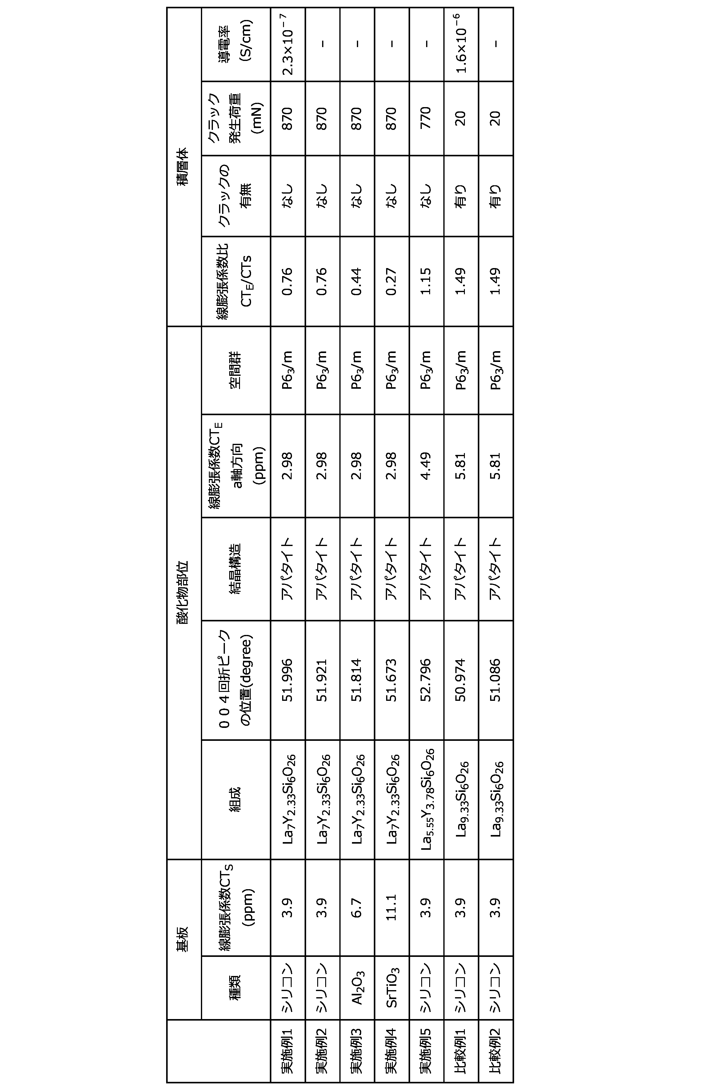
これに対して比較例で得られた積層体は、加熱によってクラックが発生してしまった。
Claims (10)
- 基板と、前記基板上に位置する酸化物部位とを備えた積層体であって、
前記酸化物部位を構成する酸化物は少なくとも二種以上の希土類元素と、シリコンと、酸素とを含み、X線回折パターンにおいて(004)面に由来する回折ピークが2θ=51.9°±0.9°の位置に観察され、且つ、アパタイト型の結晶構造を有し、
前記基板の線膨張係数に対する前記酸化物のa軸方向の線膨張係数の比が0.15以上1.45以下である、積層体。 - 前記基板がシリコンを含むものである、請求項1に記載の積層体。
- 前記基板が、シリコンの酸化物及び結晶性シリコンの少なくとも一種を含む、請求項2に記載の積層体。
- 前記酸化物が、ランタン族元素と、イットリウム及びスカンジウムの少なくとも一種以上を含む、請求項1ないし3のいずれか一項に記載の積層体。
- 前記酸化物が、式(1):A9.3+x-aYa[Si6.0-yMy]O26.0+z(式中、Aは、La、Ce、Pr、Nd、Pm、Sm、Eu、Gd、Tb、Dy、Ho、Er、Yb、Lu、Be、Mg、Ca、Sr、及びBaからなる群から選ばれた一種又は二種以上の元素であり、少なくともLaを含む。Mは、Mg、Al、Sc、Ti、V、Cr、Mn、Fe、Co、Ni、Ga、Ge、Zr、Ta、Nb、B、Zn、Sn、W及びMoからなる群から選ばれた一種又は二種以上の元素である。xは-1.4以上1.5以下の数である。yは0.0以上3.0以下の数である。zは-5.0以上5.2以下の数である。aは0.1以上10.4以下の数である。Siのモル数に対するAのモル数の比率は1.4以上3.7以下である。)で表される、請求項1ないし4のいずれか一項に記載の積層体。
- 式(1)で表される酸化物が、空間群P63/mを有し、
式(1)においてAが少なくともLaを含み、
Laが占めるサイトのうち、ワイコフ位置6hサイトよりも4fサイトに多くのYが存在する、請求項5に記載の積層体。 - 更に電極を有する、請求項1ないし6のいずれか一項に記載の積層体。
- 前記電極が、
Au、Ag、Pt、Pd、Rh、Ru、Os及びIrからなる群より選ばれる一種又は二種以上の金属、
カチオン伝導炭酸塩、並びに
Liと、Ce及びSmのうち少なくとも一種とを含む酸化物、を含む、請求項7に記載の積層体。 - ガスセンサとして用いられる、請求項8に記載の積層体。
- 前記基板が貫通孔を有する、請求項1ないし9のいずれか一項に記載の積層体。
Priority Applications (5)
| Application Number | Priority Date | Filing Date | Title |
|---|---|---|---|
| KR1020237031253A KR20230161435A (ko) | 2021-03-31 | 2022-02-17 | 적층체 |
| EP22779626.5A EP4317548B1 (en) | 2021-03-31 | 2022-02-17 | Multilayer body |
| CN202280022835.XA CN117043399A (zh) | 2021-03-31 | 2022-02-17 | 层叠体 |
| JP2023510637A JPWO2022209399A1 (ja) | 2021-03-31 | 2022-02-17 | |
| US18/279,458 US20240229296A9 (en) | 2021-03-31 | 2022-02-17 | Multilayer body |
Applications Claiming Priority (2)
| Application Number | Priority Date | Filing Date | Title |
|---|---|---|---|
| JP2021-061792 | 2021-03-31 | ||
| JP2021061792 | 2021-03-31 |
Publications (1)
| Publication Number | Publication Date |
|---|---|
| WO2022209399A1 true WO2022209399A1 (ja) | 2022-10-06 |
Family
ID=83455958
Family Applications (1)
| Application Number | Title | Priority Date | Filing Date |
|---|---|---|---|
| PCT/JP2022/006480 Ceased WO2022209399A1 (ja) | 2021-03-31 | 2022-02-17 | 積層体 |
Country Status (7)
| Country | Link |
|---|---|
| US (1) | US20240229296A9 (ja) |
| EP (1) | EP4317548B1 (ja) |
| JP (1) | JPWO2022209399A1 (ja) |
| KR (1) | KR20230161435A (ja) |
| CN (1) | CN117043399A (ja) |
| TW (1) | TW202305156A (ja) |
| WO (1) | WO2022209399A1 (ja) |
Citations (6)
| Publication number | Priority date | Publication date | Assignee | Title |
|---|---|---|---|---|
| JP2011165424A (ja) * | 2010-02-08 | 2011-08-25 | Hyogo Prefecture | 固体酸化物型燃料電池用セル及びその製造方法 |
| JP2013064194A (ja) * | 2011-08-31 | 2013-04-11 | Honda Motor Co Ltd | 複合酸化物膜及びその製造方法 |
| JP2017024931A (ja) * | 2015-07-17 | 2017-02-02 | 株式会社豊田中央研究所 | アパタイト型ランタンシリケート前駆体薄膜、その製造方法、並びに、アパタイト型ランタンシリケート薄膜 |
| WO2017018149A1 (ja) | 2015-07-30 | 2017-02-02 | 三井金属鉱業株式会社 | 基板・配向性アパタイト型複合酸化物膜複合体及びその製造方法 |
| US20180183068A1 (en) | 2015-01-07 | 2018-06-28 | Mitsui Mining & Smelting Co., Ltd. | Oriented Apatite-Type Oxide Ion Conductor and Method for Manufacturing Same |
| JP2018163753A (ja) * | 2017-03-24 | 2018-10-18 | 株式会社豊田中央研究所 | 固体酸化物形燃料電池 |
Family Cites Families (2)
| Publication number | Priority date | Publication date | Assignee | Title |
|---|---|---|---|---|
| JP7093545B2 (ja) * | 2017-10-12 | 2022-06-30 | 国立大学法人 名古屋工業大学 | ケイ酸ランタンオキシアパタイトの板状結晶、及びその製造方法、並びにケイ酸ランタンオキシアパタイトの板状結晶を用いた結晶配向アパタイト |
| JP7309702B2 (ja) * | 2018-06-08 | 2023-07-18 | 三井金属鉱業株式会社 | 固体電解質及び固体電解質接合体 |
-
2022
- 2022-02-17 EP EP22779626.5A patent/EP4317548B1/en active Active
- 2022-02-17 WO PCT/JP2022/006480 patent/WO2022209399A1/ja not_active Ceased
- 2022-02-17 KR KR1020237031253A patent/KR20230161435A/ko active Pending
- 2022-02-17 CN CN202280022835.XA patent/CN117043399A/zh active Pending
- 2022-02-17 US US18/279,458 patent/US20240229296A9/en active Pending
- 2022-02-17 JP JP2023510637A patent/JPWO2022209399A1/ja active Pending
- 2022-03-02 TW TW111107531A patent/TW202305156A/zh unknown
Patent Citations (6)
| Publication number | Priority date | Publication date | Assignee | Title |
|---|---|---|---|---|
| JP2011165424A (ja) * | 2010-02-08 | 2011-08-25 | Hyogo Prefecture | 固体酸化物型燃料電池用セル及びその製造方法 |
| JP2013064194A (ja) * | 2011-08-31 | 2013-04-11 | Honda Motor Co Ltd | 複合酸化物膜及びその製造方法 |
| US20180183068A1 (en) | 2015-01-07 | 2018-06-28 | Mitsui Mining & Smelting Co., Ltd. | Oriented Apatite-Type Oxide Ion Conductor and Method for Manufacturing Same |
| JP2017024931A (ja) * | 2015-07-17 | 2017-02-02 | 株式会社豊田中央研究所 | アパタイト型ランタンシリケート前駆体薄膜、その製造方法、並びに、アパタイト型ランタンシリケート薄膜 |
| WO2017018149A1 (ja) | 2015-07-30 | 2017-02-02 | 三井金属鉱業株式会社 | 基板・配向性アパタイト型複合酸化物膜複合体及びその製造方法 |
| JP2018163753A (ja) * | 2017-03-24 | 2018-10-18 | 株式会社豊田中央研究所 | 固体酸化物形燃料電池 |
Non-Patent Citations (1)
| Title |
|---|
| See also references of EP4317548A4 |
Also Published As
| Publication number | Publication date |
|---|---|
| KR20230161435A (ko) | 2023-11-27 |
| EP4317548A4 (en) | 2024-10-23 |
| CN117043399A (zh) | 2023-11-10 |
| US20240133075A1 (en) | 2024-04-25 |
| EP4317548A1 (en) | 2024-02-07 |
| JPWO2022209399A1 (ja) | 2022-10-06 |
| EP4317548B1 (en) | 2025-10-22 |
| US20240229296A9 (en) | 2024-07-11 |
| TW202305156A (zh) | 2023-02-01 |
Similar Documents
| Publication | Publication Date | Title |
|---|---|---|
| JP7294371B2 (ja) | スピネル材料粉体、インターコネクタ保護膜およびスピネル材料粉体の製造方法 | |
| JP6088715B1 (ja) | 基板・配向性アパタイト型複合酸化物膜複合体及びその製造方法 | |
| TWI874313B (zh) | 具中間層之固體電解質接合體 | |
| WO2016111110A1 (ja) | 配向性アパタイト型酸化物イオン伝導体及びその製造方法 | |
| JP7291031B2 (ja) | 固体電解質接合体 | |
| JP7617982B2 (ja) | 固体電解質及び固体電解質接合体 | |
| Liu et al. | Preparation and characterization of La0. 9Sr0. 1Ga0. 8Mg0. 2O3− δ thin film on the porous cathode for SOFC | |
| EP3754668B1 (en) | Oriented apatite type oxide ion conductor and method for producing same | |
| WO2022209399A1 (ja) | 積層体 | |
| JP5883492B1 (ja) | 燃料電池 | |
| JP7681986B2 (ja) | 固体電解質接合体及びその製造方法 | |
| JP4038628B2 (ja) | 酸化物イオン導電体およびその製造法並びに固体電解質型燃料電池 | |
| JP7813180B2 (ja) | 積層体 | |
| JP2024078311A (ja) | 積層体及び電気化学素子 | |
| JP7300440B2 (ja) | 固体電解質接合体 | |
| JP4428735B2 (ja) | 酸化物イオン導電体および固体電解質型燃料電池 | |
| CN114787619A (zh) | 二氧化碳传感器 | |
| WO2026023454A1 (ja) | 電気化学セル | |
| JP2003048778A (ja) | 酸化物イオン導電体及びその製造方法 | |
| JP2003212653A (ja) | 酸化物イオン導電体および固体酸化物型燃料電池 |
Legal Events
| Date | Code | Title | Description |
|---|---|---|---|
| 121 | Ep: the epo has been informed by wipo that ep was designated in this application |
Ref document number: 22779626 Country of ref document: EP Kind code of ref document: A1 |
|
| ENP | Entry into the national phase |
Ref document number: 2023510637 Country of ref document: JP Kind code of ref document: A |
|
| WWE | Wipo information: entry into national phase |
Ref document number: 18279458 Country of ref document: US |
|
| WWE | Wipo information: entry into national phase |
Ref document number: 202280022835.X Country of ref document: CN |
|
| WWE | Wipo information: entry into national phase |
Ref document number: 2022779626 Country of ref document: EP |
|
| ENP | Entry into the national phase |
Ref document number: 2022779626 Country of ref document: EP Effective date: 20231031 |
|
| NENP | Non-entry into the national phase |
Ref country code: DE |
|
| WWG | Wipo information: grant in national office |
Ref document number: 2022779626 Country of ref document: EP |