WO2022209444A1 - 空気調和システム、空気調和システムの冷媒量推定方法、空気調和機及び空気調和機の冷媒量推定方法 - Google Patents
空気調和システム、空気調和システムの冷媒量推定方法、空気調和機及び空気調和機の冷媒量推定方法 Download PDFInfo
- Publication number
- WO2022209444A1 WO2022209444A1 PCT/JP2022/007461 JP2022007461W WO2022209444A1 WO 2022209444 A1 WO2022209444 A1 WO 2022209444A1 JP 2022007461 W JP2022007461 W JP 2022007461W WO 2022209444 A1 WO2022209444 A1 WO 2022209444A1
- Authority
- WO
- WIPO (PCT)
- Prior art keywords
- refrigerant
- value
- amount
- unit
- feature
- Prior art date
- Legal status (The legal status is an assumption and is not a legal conclusion. Google has not performed a legal analysis and makes no representation as to the accuracy of the status listed.)
- Ceased
Links
Images






Classifications
-
- F—MECHANICAL ENGINEERING; LIGHTING; HEATING; WEAPONS; BLASTING
- F24—HEATING; RANGES; VENTILATING
- F24F—AIR-CONDITIONING; AIR-HUMIDIFICATION; VENTILATION; USE OF AIR CURRENTS FOR SCREENING
- F24F11/00—Control or safety arrangements
- F24F11/62—Control or safety arrangements characterised by the type of control or by internal processing, e.g. using fuzzy logic, adaptive control or estimation of values
- F24F11/63—Electronic processing
-
- F—MECHANICAL ENGINEERING; LIGHTING; HEATING; WEAPONS; BLASTING
- F25—REFRIGERATION OR COOLING; COMBINED HEATING AND REFRIGERATION SYSTEMS; HEAT PUMP SYSTEMS; MANUFACTURE OR STORAGE OF ICE; LIQUEFACTION SOLIDIFICATION OF GASES
- F25B—REFRIGERATION MACHINES, PLANTS OR SYSTEMS; COMBINED HEATING AND REFRIGERATION SYSTEMS; HEAT PUMP SYSTEMS
- F25B49/00—Arrangement or mounting of control or safety devices
- F25B49/02—Arrangement or mounting of control or safety devices for compression type machines, plants or systems
-
- F—MECHANICAL ENGINEERING; LIGHTING; HEATING; WEAPONS; BLASTING
- F24—HEATING; RANGES; VENTILATING
- F24F—AIR-CONDITIONING; AIR-HUMIDIFICATION; VENTILATION; USE OF AIR CURRENTS FOR SCREENING
- F24F11/00—Control or safety arrangements
- F24F11/30—Control or safety arrangements for purposes related to the operation of the system, e.g. for safety or monitoring
-
- F—MECHANICAL ENGINEERING; LIGHTING; HEATING; WEAPONS; BLASTING
- F24—HEATING; RANGES; VENTILATING
- F24F—AIR-CONDITIONING; AIR-HUMIDIFICATION; VENTILATION; USE OF AIR CURRENTS FOR SCREENING
- F24F11/00—Control or safety arrangements
- F24F11/30—Control or safety arrangements for purposes related to the operation of the system, e.g. for safety or monitoring
- F24F11/32—Responding to malfunctions or emergencies
- F24F11/36—Responding to malfunctions or emergencies to leakage of heat-exchange fluid
-
- F—MECHANICAL ENGINEERING; LIGHTING; HEATING; WEAPONS; BLASTING
- F24—HEATING; RANGES; VENTILATING
- F24F—AIR-CONDITIONING; AIR-HUMIDIFICATION; VENTILATION; USE OF AIR CURRENTS FOR SCREENING
- F24F11/00—Control or safety arrangements
- F24F11/30—Control or safety arrangements for purposes related to the operation of the system, e.g. for safety or monitoring
- F24F11/49—Control or safety arrangements for purposes related to the operation of the system, e.g. for safety or monitoring ensuring correct operation, e.g. by trial operation or configuration checks
-
- F—MECHANICAL ENGINEERING; LIGHTING; HEATING; WEAPONS; BLASTING
- F25—REFRIGERATION OR COOLING; COMBINED HEATING AND REFRIGERATION SYSTEMS; HEAT PUMP SYSTEMS; MANUFACTURE OR STORAGE OF ICE; LIQUEFACTION SOLIDIFICATION OF GASES
- F25B—REFRIGERATION MACHINES, PLANTS OR SYSTEMS; COMBINED HEATING AND REFRIGERATION SYSTEMS; HEAT PUMP SYSTEMS
- F25B1/00—Compression machines, plants or systems with non-reversible cycle
-
- F—MECHANICAL ENGINEERING; LIGHTING; HEATING; WEAPONS; BLASTING
- F25—REFRIGERATION OR COOLING; COMBINED HEATING AND REFRIGERATION SYSTEMS; HEAT PUMP SYSTEMS; MANUFACTURE OR STORAGE OF ICE; LIQUEFACTION SOLIDIFICATION OF GASES
- F25B—REFRIGERATION MACHINES, PLANTS OR SYSTEMS; COMBINED HEATING AND REFRIGERATION SYSTEMS; HEAT PUMP SYSTEMS
- F25B49/00—Arrangement or mounting of control or safety devices
- F25B49/005—Arrangement or mounting of control or safety devices of safety devices
-
- F—MECHANICAL ENGINEERING; LIGHTING; HEATING; WEAPONS; BLASTING
- F24—HEATING; RANGES; VENTILATING
- F24F—AIR-CONDITIONING; AIR-HUMIDIFICATION; VENTILATION; USE OF AIR CURRENTS FOR SCREENING
- F24F11/00—Control or safety arrangements
- F24F11/50—Control or safety arrangements characterised by user interfaces or communication
- F24F11/56—Remote control
- F24F11/58—Remote control using Internet communication
-
- F—MECHANICAL ENGINEERING; LIGHTING; HEATING; WEAPONS; BLASTING
- F25—REFRIGERATION OR COOLING; COMBINED HEATING AND REFRIGERATION SYSTEMS; HEAT PUMP SYSTEMS; MANUFACTURE OR STORAGE OF ICE; LIQUEFACTION SOLIDIFICATION OF GASES
- F25B—REFRIGERATION MACHINES, PLANTS OR SYSTEMS; COMBINED HEATING AND REFRIGERATION SYSTEMS; HEAT PUMP SYSTEMS
- F25B13/00—Compression machines, plants or systems, with reversible cycle
-
- F—MECHANICAL ENGINEERING; LIGHTING; HEATING; WEAPONS; BLASTING
- F25—REFRIGERATION OR COOLING; COMBINED HEATING AND REFRIGERATION SYSTEMS; HEAT PUMP SYSTEMS; MANUFACTURE OR STORAGE OF ICE; LIQUEFACTION SOLIDIFICATION OF GASES
- F25B—REFRIGERATION MACHINES, PLANTS OR SYSTEMS; COMBINED HEATING AND REFRIGERATION SYSTEMS; HEAT PUMP SYSTEMS
- F25B2313/00—Compression machines, plants or systems with reversible cycle not otherwise provided for
- F25B2313/023—Compression machines, plants or systems with reversible cycle not otherwise provided for using multiple indoor units
- F25B2313/0233—Compression machines, plants or systems with reversible cycle not otherwise provided for using multiple indoor units in parallel arrangements
-
- F—MECHANICAL ENGINEERING; LIGHTING; HEATING; WEAPONS; BLASTING
- F25—REFRIGERATION OR COOLING; COMBINED HEATING AND REFRIGERATION SYSTEMS; HEAT PUMP SYSTEMS; MANUFACTURE OR STORAGE OF ICE; LIQUEFACTION SOLIDIFICATION OF GASES
- F25B—REFRIGERATION MACHINES, PLANTS OR SYSTEMS; COMBINED HEATING AND REFRIGERATION SYSTEMS; HEAT PUMP SYSTEMS
- F25B2313/00—Compression machines, plants or systems with reversible cycle not otherwise provided for
- F25B2313/031—Sensor arrangements
- F25B2313/0314—Temperature sensors near the indoor heat exchanger
-
- F—MECHANICAL ENGINEERING; LIGHTING; HEATING; WEAPONS; BLASTING
- F25—REFRIGERATION OR COOLING; COMBINED HEATING AND REFRIGERATION SYSTEMS; HEAT PUMP SYSTEMS; MANUFACTURE OR STORAGE OF ICE; LIQUEFACTION SOLIDIFICATION OF GASES
- F25B—REFRIGERATION MACHINES, PLANTS OR SYSTEMS; COMBINED HEATING AND REFRIGERATION SYSTEMS; HEAT PUMP SYSTEMS
- F25B2313/00—Compression machines, plants or systems with reversible cycle not otherwise provided for
- F25B2313/031—Sensor arrangements
- F25B2313/0315—Temperature sensors near the outdoor heat exchanger
-
- F—MECHANICAL ENGINEERING; LIGHTING; HEATING; WEAPONS; BLASTING
- F25—REFRIGERATION OR COOLING; COMBINED HEATING AND REFRIGERATION SYSTEMS; HEAT PUMP SYSTEMS; MANUFACTURE OR STORAGE OF ICE; LIQUEFACTION SOLIDIFICATION OF GASES
- F25B—REFRIGERATION MACHINES, PLANTS OR SYSTEMS; COMBINED HEATING AND REFRIGERATION SYSTEMS; HEAT PUMP SYSTEMS
- F25B2500/00—Problems to be solved
- F25B2500/19—Calculation of parameters
-
- F—MECHANICAL ENGINEERING; LIGHTING; HEATING; WEAPONS; BLASTING
- F25—REFRIGERATION OR COOLING; COMBINED HEATING AND REFRIGERATION SYSTEMS; HEAT PUMP SYSTEMS; MANUFACTURE OR STORAGE OF ICE; LIQUEFACTION SOLIDIFICATION OF GASES
- F25B—REFRIGERATION MACHINES, PLANTS OR SYSTEMS; COMBINED HEATING AND REFRIGERATION SYSTEMS; HEAT PUMP SYSTEMS
- F25B2500/00—Problems to be solved
- F25B2500/22—Preventing, detecting or repairing leaks of refrigeration fluids
- F25B2500/222—Detecting refrigerant leaks
-
- F—MECHANICAL ENGINEERING; LIGHTING; HEATING; WEAPONS; BLASTING
- F25—REFRIGERATION OR COOLING; COMBINED HEATING AND REFRIGERATION SYSTEMS; HEAT PUMP SYSTEMS; MANUFACTURE OR STORAGE OF ICE; LIQUEFACTION SOLIDIFICATION OF GASES
- F25B—REFRIGERATION MACHINES, PLANTS OR SYSTEMS; COMBINED HEATING AND REFRIGERATION SYSTEMS; HEAT PUMP SYSTEMS
- F25B2500/00—Problems to be solved
- F25B2500/24—Low amount of refrigerant in the system
-
- F—MECHANICAL ENGINEERING; LIGHTING; HEATING; WEAPONS; BLASTING
- F25—REFRIGERATION OR COOLING; COMBINED HEATING AND REFRIGERATION SYSTEMS; HEAT PUMP SYSTEMS; MANUFACTURE OR STORAGE OF ICE; LIQUEFACTION SOLIDIFICATION OF GASES
- F25B—REFRIGERATION MACHINES, PLANTS OR SYSTEMS; COMBINED HEATING AND REFRIGERATION SYSTEMS; HEAT PUMP SYSTEMS
- F25B2700/00—Sensing or detecting of parameters; Sensors therefor
- F25B2700/04—Refrigerant level
-
- F—MECHANICAL ENGINEERING; LIGHTING; HEATING; WEAPONS; BLASTING
- F25—REFRIGERATION OR COOLING; COMBINED HEATING AND REFRIGERATION SYSTEMS; HEAT PUMP SYSTEMS; MANUFACTURE OR STORAGE OF ICE; LIQUEFACTION SOLIDIFICATION OF GASES
- F25B—REFRIGERATION MACHINES, PLANTS OR SYSTEMS; COMBINED HEATING AND REFRIGERATION SYSTEMS; HEAT PUMP SYSTEMS
- F25B2700/00—Sensing or detecting of parameters; Sensors therefor
- F25B2700/19—Pressures
- F25B2700/193—Pressures of the compressor
- F25B2700/1931—Discharge pressures
-
- F—MECHANICAL ENGINEERING; LIGHTING; HEATING; WEAPONS; BLASTING
- F25—REFRIGERATION OR COOLING; COMBINED HEATING AND REFRIGERATION SYSTEMS; HEAT PUMP SYSTEMS; MANUFACTURE OR STORAGE OF ICE; LIQUEFACTION SOLIDIFICATION OF GASES
- F25B—REFRIGERATION MACHINES, PLANTS OR SYSTEMS; COMBINED HEATING AND REFRIGERATION SYSTEMS; HEAT PUMP SYSTEMS
- F25B2700/00—Sensing or detecting of parameters; Sensors therefor
- F25B2700/19—Pressures
- F25B2700/193—Pressures of the compressor
- F25B2700/1933—Suction pressures
-
- F—MECHANICAL ENGINEERING; LIGHTING; HEATING; WEAPONS; BLASTING
- F25—REFRIGERATION OR COOLING; COMBINED HEATING AND REFRIGERATION SYSTEMS; HEAT PUMP SYSTEMS; MANUFACTURE OR STORAGE OF ICE; LIQUEFACTION SOLIDIFICATION OF GASES
- F25B—REFRIGERATION MACHINES, PLANTS OR SYSTEMS; COMBINED HEATING AND REFRIGERATION SYSTEMS; HEAT PUMP SYSTEMS
- F25B2700/00—Sensing or detecting of parameters; Sensors therefor
- F25B2700/21—Temperatures
- F25B2700/2104—Temperatures of an indoor room or compartment
-
- F—MECHANICAL ENGINEERING; LIGHTING; HEATING; WEAPONS; BLASTING
- F25—REFRIGERATION OR COOLING; COMBINED HEATING AND REFRIGERATION SYSTEMS; HEAT PUMP SYSTEMS; MANUFACTURE OR STORAGE OF ICE; LIQUEFACTION SOLIDIFICATION OF GASES
- F25B—REFRIGERATION MACHINES, PLANTS OR SYSTEMS; COMBINED HEATING AND REFRIGERATION SYSTEMS; HEAT PUMP SYSTEMS
- F25B2700/00—Sensing or detecting of parameters; Sensors therefor
- F25B2700/21—Temperatures
- F25B2700/2106—Temperatures of fresh outdoor air
-
- F—MECHANICAL ENGINEERING; LIGHTING; HEATING; WEAPONS; BLASTING
- F25—REFRIGERATION OR COOLING; COMBINED HEATING AND REFRIGERATION SYSTEMS; HEAT PUMP SYSTEMS; MANUFACTURE OR STORAGE OF ICE; LIQUEFACTION SOLIDIFICATION OF GASES
- F25B—REFRIGERATION MACHINES, PLANTS OR SYSTEMS; COMBINED HEATING AND REFRIGERATION SYSTEMS; HEAT PUMP SYSTEMS
- F25B2700/00—Sensing or detecting of parameters; Sensors therefor
- F25B2700/21—Temperatures
- F25B2700/2115—Temperatures of a compressor or the drive means therefor
- F25B2700/21151—Temperatures of a compressor or the drive means therefor at the suction side of the compressor
-
- F—MECHANICAL ENGINEERING; LIGHTING; HEATING; WEAPONS; BLASTING
- F25—REFRIGERATION OR COOLING; COMBINED HEATING AND REFRIGERATION SYSTEMS; HEAT PUMP SYSTEMS; MANUFACTURE OR STORAGE OF ICE; LIQUEFACTION SOLIDIFICATION OF GASES
- F25B—REFRIGERATION MACHINES, PLANTS OR SYSTEMS; COMBINED HEATING AND REFRIGERATION SYSTEMS; HEAT PUMP SYSTEMS
- F25B2700/00—Sensing or detecting of parameters; Sensors therefor
- F25B2700/21—Temperatures
- F25B2700/2115—Temperatures of a compressor or the drive means therefor
- F25B2700/21152—Temperatures of a compressor or the drive means therefor at the discharge side of the compressor
Definitions
- the present invention relates to an air conditioning system, a refrigerant amount estimation method for an air conditioning system, an air conditioner, and a refrigerant amount estimation method for an air conditioner.
- the amount of refrigerant is determined using the degree of supercooling at the outlet of the condenser under a predetermined condition of the refrigerant circuit.
- the applicant generated a model for estimating the amount of refrigerant remaining in the refrigerant circuit by multiple regression analysis using the feature value of the refrigerant circuit related to the amount of refrigerant, and estimated the amount of residual refrigerant using this model. I have applied for patent document 2 to do.
- the residual refrigerant amount is estimated using a feature amount that has a correlation with the residual refrigerant amount among the plurality of feature amounts related to the refrigerant circuit.
- these feature values may also be correlated with abnormal conditions other than the decrease in the amount of residual refrigerant due to refrigerant leakage, such as compressor failure. Therefore, if any of the feature values correlated with the remaining refrigerant amount changes due to a factor other than the refrigerant leakage, for example, a failure of a device that constitutes the refrigerant circuit, the estimation result of the remaining refrigerant amount may be erroneous.
- the feature value correlated with refrigerant leakage that appears normal at first glance may also be affected by factors other than refrigerant leakage. may have been affected by
- the present invention aims to improve the estimation accuracy of the residual refrigerant amount even when the feature value used for estimating the residual refrigerant amount is affected by other problems, and the refrigerant amount of the air conditioning system.
- An object of the present invention is to provide an estimation method, an air conditioner, and a refrigerant amount estimation method for the air conditioner.
- An air conditioning system of one aspect includes an air conditioner having a refrigerant circuit configured by connecting at least one indoor unit to an outdoor unit by refrigerant pipes, the refrigerant circuit being filled with a predetermined amount of refrigerant; It has a server that communicates with the air conditioner.
- the air conditioner includes a detection unit that detects a state quantity related to control of the air conditioner, an acquisition unit that acquires the detection value detected by the detection unit, and the detection value acquired by the acquisition unit. and a first communication unit that transmits to the server.
- the server includes a second communication unit that receives the detected value from the air conditioner, and the first an estimating unit for estimating the amount of residual refrigerant remaining in the refrigerant circuit using the detected value of the feature amount; and a determination unit that determines whether or not the detected value should be detected.
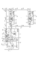
- FIG. 1 is an explanatory diagram showing an example of the air conditioner of this embodiment.
- FIG. 2 is an explanatory diagram showing an example of an outdoor unit and an indoor unit.
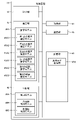
- FIG. 3 is a block diagram showing an example of a control circuit for the outdoor unit.
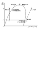
- FIG. 4 is a Mollier diagram showing how the refrigerant changes in the air conditioner.
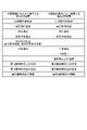
- FIG. 5 is an explanatory diagram showing an example of the first feature amount used for the first to third cooling estimation models and the second feature amount used for the cooling discrimination model.
- FIG. 6 is an explanatory diagram showing an example of the first feature amount used for the first to third heating estimation models and the second feature amount used for the heating discrimination model.
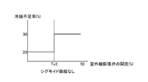
- FIG. 7A is an explanatory diagram showing an example of a case in which the estimation result by the first cooling estimation model and the estimation result by the second cooling estimation model are not interpolated with a sigmoid curve.
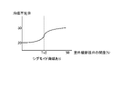
- FIG. 7B is an explanatory diagram showing an example of interpolation using a sigmoid curve between the estimation result of the first cooling estimation model and the estimation result of the second cooling estimation model.
- FIG. 8A is an explanatory diagram showing an example of a case in which the estimation result by the first heating estimation model and the estimation result by the second heating estimation model are not interpolated with a sigmoid curve.
- FIG. 8B is an explanatory diagram showing an example of interpolation using a sigmoid curve between the estimation result of the first estimation model for heating and the estimation result of the second estimation model for heating.
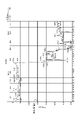
- FIG. 9 is an explanatory diagram showing an example of a distribution method of the detected value of the second feature quantity of the discriminant model.
- FIG. 10 is an explanatory diagram showing an example of abnormality detection using an outlier.
- FIG. 11 is a flowchart illustrating an example of processing operations of a control circuit involved in estimation processing.
- FIG. 12 is a flowchart illustrating an example of the processing operation of the control circuit involved in multiple regression analysis processing.
- FIG. 13 is an explanatory diagram of an example of a failure determination table within the control unit.
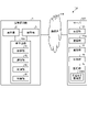
- FIG. 14 is an explanatory diagram showing an example of the air conditioning system of the second embodiment.
- FIG. 1 is an explanatory diagram showing an example of an air conditioner 1 of this embodiment.
- the air conditioner 1 shown in FIG. 1 has one outdoor unit 2 and N indoor units 3 (N is a natural number of 2 or more).
- the outdoor unit 2 is connected to each indoor unit 3 in parallel with a liquid pipe 4 and a gas pipe 5 .
- a refrigerant circuit 6 of the air conditioner 1 is formed by connecting the outdoor unit 2 and the indoor unit 3 with refrigerant pipes such as the liquid pipe 4 and the gas pipe 5 .
- FIG. 2 is an explanatory diagram showing an example of the outdoor unit 2 and N indoor units 3 .
- the outdoor unit 2 includes a compressor 11, a four-way valve 12, an outdoor heat exchanger 13, an outdoor unit expansion valve 14, a first closing valve 15, a second closing valve 16, an accumulator 17, and an outdoor It has a machine fan 18 and a control circuit 19 .
- a compressor 11, four-way valve 12, outdoor heat exchanger 13, outdoor unit expansion valve 14, first shut-off valve 15, second shut-off valve 16 and accumulator 17 each refrigerant pipe described in detail below
- An outdoor refrigerant circuit which is connected to each other and forms a part of the refrigerant circuit 6 is formed.
- the compressor 11 is, for example, a high-pressure vessel type variable capacity compressor that can vary its operating capacity in accordance with the drive of a motor (not shown) whose rotational speed is controlled by an inverter.
- the compressor 11 has a discharge pipe 21 connecting between the refrigerant discharge side thereof and the first port 12A of the four-way valve 12 .
- a suction pipe 22 connects the refrigerant suction side of the compressor 11 and the refrigerant outflow side of the accumulator 17 .
- the four-way valve 12 is a valve for switching the direction of refrigerant flow in the refrigerant circuit 6, and has first to fourth ports 12A to 12D.
- the first port 12A is connected to the refrigerant discharge side of the compressor 11 via a discharge pipe 21 .
- the second port 12B is connected to one refrigerant inlet/outlet of the outdoor heat exchanger 13 by an outdoor refrigerant pipe 23 .
- the third port 12 ⁇ /b>C is connected to the refrigerant inflow side of the accumulator 17 with an outdoor refrigerant pipe 26 .
- the 4th port 12D has connected between the 2nd closing valves 16 with the outdoor gas pipe 24. As shown in FIG.
- the outdoor heat exchanger 13 exchanges heat between the refrigerant and the outside air taken into the outdoor unit 2 by the rotation of the outdoor unit fan 18 .
- the outdoor heat exchanger 13 has one refrigerant inlet/outlet port and the second port 12B of the four-way valve 12 connected by an outdoor refrigerant pipe 26 .
- the outdoor heat exchanger 13 connects the other refrigerant inlet/outlet port and the first shutoff valve 15 with an outdoor liquid pipe 25 .
- the outdoor heat exchanger 13 functions as a condenser when the air conditioner 1 performs cooling operation, and functions as an evaporator when the air conditioner 1 performs heating operation.
- the outdoor unit expansion valve 14 is provided in the outdoor liquid pipe 25 and is an electronic expansion valve driven by a pulse motor (not shown).
- the opening of the outdoor unit expansion valve 14 is adjusted according to the number of pulses given to the pulse motor, so that the amount of refrigerant flowing into the outdoor heat exchanger 13 or the amount of refrigerant flowing out of the outdoor heat exchanger 13 is adjusted. It is an adjustment.
- the degree of opening of the outdoor unit expansion valve 14 is adjusted so that the refrigerant superheat degree on the refrigerant suction side of the compressor 11 becomes the target suction superheat degree when the air conditioner 1 is performing heating operation. Further, the degree of opening of the outdoor unit expansion valve 14 is fully opened when the air conditioner 1 is performing cooling operation.
- the refrigerant inflow side of the accumulator 17 and the third port 12C of the four-way valve 12 are connected by an outdoor refrigerant pipe 26 .
- the accumulator 17 has a suction pipe 22 connecting between the refrigerant outflow side thereof and the refrigerant inflow side of the compressor 11 .
- the accumulator 17 separates the refrigerant that has flowed into the accumulator 17 from the outdoor refrigerant pipe 26 into gas refrigerant and liquid refrigerant, and causes the compressor 11 to suck only the gas refrigerant.
- the outdoor unit fan 18 is made of a resin material and arranged near the outdoor heat exchanger 13 .
- the outdoor unit fan 18 draws outside air into the outdoor unit 2 from a suction port (not shown) in response to rotation of a fan motor (not shown), and the outside air heat-exchanged with the refrigerant in the outdoor heat exchanger 13 is discharged from an outlet (not shown) to the outside of the room. Discharge to the outside of machine 2.
- the discharge pipe 21 is provided with a discharge pressure sensor 31 for detecting the pressure of the refrigerant discharged from the compressor 11, and a discharge temperature sensor 32 for detecting the temperature of the refrigerant discharged from the compressor 11, that is, the discharge temperature. and are placed.
- a suction pressure sensor 33 for detecting the suction pressure, which is the pressure of the refrigerant sucked into the compressor 11, and the temperature of the refrigerant sucked into the compressor 11 are detected.
- An intake temperature sensor 34 is arranged.
- the temperature of the refrigerant flowing into the outdoor heat exchanger 13 or the temperature of the refrigerant flowing out of the outdoor heat exchanger 13 is detected in the outdoor liquid pipe 25 between the outdoor heat exchanger 13 and the outdoor unit expansion valve 14.
- a coolant temperature sensor 35 is arranged for the purpose.
- An outside air temperature sensor 36 for detecting the temperature of the outside air flowing into the inside of the outdoor unit 2, that is, the outside air temperature, is arranged near the suction port (not shown) of the outdoor unit 2 .
- FIG. 3 is a block diagram showing an example of the control circuit 19 of the outdoor unit 2.
- the control circuit 19 has an acquisition unit 41 , a communication unit 42 , a storage unit 43 , a control unit 44 , an estimation unit 45 and a determination unit 46 .
- the acquisition unit 41 acquires sensor values of the detection units, which are the various sensors described above.
- the communication section 42 is a communication interface that communicates with the communication section of each indoor unit 3 .
- the storage unit 43 is, for example, a flash memory, and stores control programs for the outdoor unit 2, operating state quantities such as detection values corresponding to detection signals from various sensors, driving states of the compressor 11 and the outdoor unit fan 18, each It stores operation information transmitted from the indoor unit 3 (including, for example, operation/stop information, operation modes such as cooling/heating), the rated capacity of the outdoor unit 2, the required capacity of each indoor unit 3, and the like. Furthermore, the storage unit 43 has an error log storage unit 43A that stores an error log, which will be described later.
- the control unit 44 periodically (for example, every 30 seconds) takes in the detection values of various sensors via the communication unit 42, and the signal including the operating state quantity transmitted from each indoor unit 3 is transmitted via the communication unit 42. is entered.
- the control unit 44 adjusts the degree of opening of the outdoor unit expansion valve 14 and controls the driving of the compressor 11 based on the input various information.
- the estimation unit 45 estimates the refrigerant shortage rate of the refrigerant circuit 6 using the detected value of the first feature quantity. It has a model 45A. In this embodiment, for example, a relative amount of refrigerant is used as the amount of refrigerant remaining in the refrigerant circuit 6 . Specifically, the estimation model 45A estimates the refrigerant shortage rate of the refrigerant circuit 6 (when the specified amount of refrigerant is assumed to be 100%, the amount decreased from this specified amount; the same applies hereinafter).
- the estimation model 45A includes a first cooling estimation model 45A1, a second cooling estimation model 45A2, a third cooling estimation model 45A3, a first heating estimation model 45A4, and a second heating estimation model 45A4. It has an estimation model 45A5 and a third heating estimation model 45A6. Each of these estimation models will be described in detail later.
- the determination unit 46 determines the detected value of the first feature value to be used for estimating the refrigerant shortage rate by the estimation unit 45 by using the detected value of the second feature value, which will be described later, among the operating state quantities. It has a discriminant model 46A that discriminates whether or not.
- the determination model 46A has a cooling mode determination model 46B used when the air conditioner 1 is performing cooling operation and a heating mode determination model 46C used when the air conditioner 1 is performing heating operation. . Each of these discriminant models will be described in detail later.
- the indoor unit 3 has an indoor heat exchanger 51 , an indoor unit expansion valve 52 , a liquid pipe connection portion 53 , a gas pipe connection portion 54 and an indoor unit fan 55 .
- the indoor heat exchanger 51, the indoor unit expansion valve 52, the liquid pipe connection portion 53, and the gas pipe connection portion 54 are connected to each other by refrigerant pipes, which will be described later, and constitute a part of the refrigerant circuit 6. configure.
- the indoor heat exchanger 51 exchanges heat between the refrigerant and the indoor air taken into the indoor unit 3 through a suction port (not shown) by the rotation of the indoor unit fan 55 .
- one refrigerant inlet/outlet port and the liquid pipe connecting portion 53 are connected by an indoor liquid pipe 56 .
- the other refrigerant inlet/outlet port and the gas pipe connecting portion 54 are connected by an indoor gas pipe 57 .
- the indoor heat exchanger 51 functions as a condenser when the air conditioner 1 performs heating operation.
- the indoor heat exchanger 51 functions as an evaporator when the air conditioner 1 performs cooling operation.
- the indoor unit expansion valve 52 is provided in the indoor liquid pipe 56 and is an electronic expansion valve.
- the degree of opening of the indoor unit expansion valve 52 is adjusted to the refrigerant outlet (gas pipe connection 54 side) of the indoor heat exchanger 51. ) is adjusted to the target refrigerant superheat degree.
- the indoor heat exchanger 51 functions as a condenser, that is, when the indoor unit 3 performs heating operation
- the degree of opening of the indoor unit expansion valve 52 is determined by the refrigerant outlet of the indoor heat exchanger 51 (liquid pipe connection portion 53 side) is adjusted to the target refrigerant subcooling degree.
- the target refrigerant superheating degree and the refrigerant supercooling degree are the refrigerant superheating degree and the refrigerant supercooling degree necessary for the indoor unit 3 to exhibit sufficient cooling capacity or heating capacity.
- the indoor unit fan 55 is made of a resin material and arranged near the indoor heat exchanger 51 .
- the indoor unit fan 55 is rotated by a fan motor (not shown) to take indoor air into the interior of the indoor unit 3 from a suction port (not shown), and the indoor air heat-exchanged with the refrigerant in the indoor heat exchanger 51 is discharged from an outlet (not shown). released into the room from
- Various sensors are provided in the indoor unit 3.
- a gas-side temperature sensor 62 is arranged to detect the machine-side heat exchanger inlet temperature.
- a suction temperature sensor 63 that detects the temperature of indoor air flowing into the interior of the indoor unit 3, that is, the suction temperature, is arranged near the suction port (not shown) of the indoor unit 3 .
- the four-way valve 12 is switched so that the first port 12A and the fourth port 12D communicate and the second port 12B and the third port 12C communicate. ing.
- the refrigerant circuit 6 becomes a heating cycle in which each indoor heat exchanger 51 functions as a condenser and the outdoor heat exchanger 13 functions as an evaporator.
- the flow of the refrigerant during the heating operation is represented by solid arrows shown in FIG.
- the refrigerant discharged from the compressor 11 flows through the discharge pipe 21, flows into the four-way valve 12, flows from the four-way valve 12 through the outdoor gas pipe 24, It flows into the gas line 5 via the second closing valve 16 .
- the refrigerant flowing through the gas pipe 5 is branched to each indoor unit 3 via each gas pipe connection portion 54 .
- the refrigerant that has flowed into each indoor unit 3 flows through each indoor gas pipe 57 and flows into each indoor heat exchanger 51 .
- the refrigerant that has flowed into each indoor heat exchanger 51 is condensed by exchanging heat with indoor air taken into each indoor unit 3 by rotation of each indoor unit fan 55 .
- each indoor heat exchanger 51 functions as a condenser, and the indoor air heated by the refrigerant in each indoor heat exchanger 51 is blown into the room from an air outlet (not shown), whereby each indoor unit 3 is installed. The room is then heated.
- the degree of opening of the refrigerant flowing into each indoor liquid pipe 56 from each indoor heat exchanger 51 is adjusted so that the refrigerant supercooling degree at the refrigerant outlet side of each indoor heat exchanger 51 becomes the target refrigerant supercooling degree.
- the pressure is reduced.
- the target refrigerant subcooling degree is determined based on the cooling capacity required by each indoor unit 3 .
- each indoor unit expansion valve 52 flows out from each indoor liquid pipe 56 to the liquid pipe 4 via each liquid pipe connecting portion 53 .
- the refrigerant merged in the liquid pipe 4 flows into the outdoor unit 2 via the first closing valve 15 .
- the refrigerant that has flowed into the first closing valve 15 of the outdoor unit 2 flows through the outdoor liquid pipe 25, passes through the outdoor unit expansion valve 14, and is decompressed.
- the refrigerant decompressed by the outdoor unit expansion valve 14 flows through the outdoor liquid pipe 25 and into the outdoor heat exchanger 13, and exchanges heat with the outside air that has flowed in from the suction port (not shown) of the outdoor unit 2 due to the rotation of the outdoor unit fan 18. and evaporate.
- the refrigerant flowing out from the outdoor heat exchanger 13 to the outdoor refrigerant pipe 26 flows into the four-way valve 12, the outdoor refrigerant pipe 26, the accumulator 17 and the suction pipe 22 in this order, is sucked into the compressor 11, is compressed again, and passes through the four-way valve. It exits into the outdoor gas pipe 24 via twelve first ports 12A and fourth ports 12D.
- the four-way valve 12 is arranged such that the first port 12A and the second port 12B communicate with each other, and the third port 12C and the fourth port 12D communicate with each other. is switching to Thereby, the refrigerant circuit 6 becomes a cooling cycle in which each indoor heat exchanger 51 functions as an evaporator and the outdoor heat exchanger 13 functions as a condenser.
- the flow of the refrigerant during the cooling operation is represented by the dashed arrow shown in FIG.
- the refrigerant discharged from the compressor 11 flows through the discharge pipe 21, flows into the four-way valve 12, flows from the four-way valve 12 through the outdoor refrigerant pipe 26, and heats the outside. It flows into exchanger 13 .
- the refrigerant that has flowed into the outdoor heat exchanger 13 is condensed by exchanging heat with the outdoor air taken into the outdoor unit 2 by the rotation of the outdoor unit fan 18 .
- the outdoor heat exchanger 13 functions as a condenser, and the indoor air heated by the refrigerant in the outdoor heat exchanger 13 is blown out of the room through an air outlet (not shown).
- the refrigerant that has flowed from the outdoor heat exchanger 13 into the outdoor liquid pipe 25 is decompressed through the outdoor unit expansion valve 14 that is fully opened.
- the refrigerant decompressed by the outdoor unit expansion valve 14 flows through the liquid pipe 4 via the first closing valve 15 and is divided into the indoor units 3 .
- the refrigerant that has flowed into each indoor unit 3 flows through the indoor liquid pipe 56 through each liquid pipe connection portion 53, and the degree of refrigerant supercooling at the refrigerant outlet of the indoor heat exchanger 51 is adjusted to the degree of opening at which the degree of refrigerant supercooling becomes the target degree of refrigerant supercooling. After passing through the indoor unit expansion valve 52, the pressure is reduced.
- each indoor heat exchanger 51 functions as an evaporator, and the indoor air cooled by the refrigerant in each indoor heat exchanger 51 is blown into the room from an air outlet (not shown), whereby each indoor unit 3 is installed. Air conditioning in the room is performed.
- the refrigerant flowing from the indoor heat exchanger 51 to the gas pipe 5 via the gas pipe connection 54 flows to the outdoor gas pipe 24 via the second shut-off valve 16 of the outdoor unit 2 and flows to the fourth port of the four-way valve 12.
- Flow into 12D The refrigerant that has flowed into the fourth port 12D of the four-way valve 12 flows into the refrigerant inflow side of the accumulator 17 from the third port 12C.
- Refrigerant that has flowed in from the refrigerant inflow side of the accumulator 17 flows through the suction pipe 22, is sucked into the compressor 11, and is compressed again.
- An acquisition unit 41 in the control circuit 19 acquires sensor values of the discharge pressure sensor 31, the discharge temperature sensor 32, the suction pressure sensor 33, the suction temperature sensor 63, the refrigerant temperature sensor 35, and the outside air temperature sensor 36 in the outdoor unit 2. . Furthermore, the acquiring unit 41 acquires the sensor values of the liquid-side refrigerant temperature sensor 61 , the gas-side temperature sensor 62 , and the intake temperature sensor 63 of each indoor unit 3 .
- FIG. 4 is a Mollier diagram showing the refrigeration cycle of the air conditioner 1.
- the outdoor heat exchanger 13 functions as a condenser
- the indoor heat exchanger 51 functions as an evaporator.
- the outdoor heat exchanger 13 functions as an evaporator
- the indoor heat exchanger 51 functions as a condenser.
- the compressor 11 compresses the low-temperature, low-pressure gas refrigerant flowing from the evaporator and discharges the high-temperature, high-pressure gas refrigerant (refrigerant in the state of point B in FIG. 4).
- the temperature of the gas refrigerant discharged from the compressor 11 is the discharge temperature, and the discharge temperature is detected by the discharge temperature sensor 32 .
- the condenser exchanges heat with air to condense the high-temperature, high-pressure gas refrigerant from the compressor 11 .
- the temperature of the liquid refrigerant decreases due to sensible heat change, resulting in a supercooled state (state of point C in FIG. 4).
- the high-pressure saturation temperature is the temperature at which the gas refrigerant changes to the liquid refrigerant due to latent heat change, and the temperature of the refrigerant in a supercooled state at the outlet of the condenser is the heat exchange outlet temperature.
- the high pressure saturation temperature is a temperature corresponding to the pressure value detected by the discharge pressure sensor 31 (pressure value P2 indicated as "HPS" in FIG. 4).
- the heat exchange outlet temperature is the temperature of the refrigerant flowing through the outdoor liquid pipe 25 and is detected by the refrigerant temperature sensor 35 .
- the expansion valve reduces the pressure of the low-temperature, high-pressure refrigerant that has flowed out of the condenser to become a gas-liquid two-phase refrigerant (refrigerant in the state of point D in FIG. 4) in which gas and liquid are mixed.
- the evaporator evaporates the inflowing gas-liquid two-phase refrigerant by exchanging heat with air.
- the temperature of the gas refrigerant rises due to the change in sensible heat and enters a superheated state (state of point A in FIG. 4), and compression It is sucked into the aircraft 11.
- the low-pressure saturation temperature is the temperature at which the liquid refrigerant changes into the gas refrigerant due to latent heat change.
- the low-pressure saturation temperature is a temperature corresponding to the pressure value detected by the suction pressure sensor 33 (pressure value P1 indicated as "LPS" in FIG. 4).
- the temperature of the refrigerant that is superheated by the evaporator and sucked into the compressor 11 is the suction temperature.
- the intake temperature is detected by an intake temperature sensor 34 .
- the degree of supercooling of the refrigerant that is in a supercooled state when flowing out of the condenser is determined by the refrigerant temperature at the refrigerant outlet of the heat exchanger functioning as a condenser (the heat exchange outlet described above) from the high-pressure saturation temperature. temperature). Also, the degree of suction superheat of the refrigerant that is in a superheated state when flowing out of the evaporator can be calculated by subtracting the suction temperature from the low-pressure saturation temperature.
- FIG. 5 is an explanatory diagram showing an example of the first feature amount used for the first to third cooling estimation models 45A1, 45A2, and 45A3 and the second feature amount used for the cooling discrimination model 46B.
- the first feature quantity used in the first to third cooling estimation models 45A1, 45A2, and 45A3 includes, for example, the rotation speed of the compressor 11, the high-pressure saturation temperature, the intake temperature, the low-pressure refrigerant temperature, the degree of refrigerant subcooling, (outdoor heat exchange subcool) and outside air temperature.
- the rotation speed of the compressor 11 is detected by a rotation speed sensor (not shown) of the compressor 11 .
- the high-pressure saturation temperature is a temperature-converted value of the pressure value detected by the discharge pressure sensor 31 .
- the intake temperature is detected by an intake temperature sensor 34 .
- the low-pressure refrigerant temperature is the temperature of the refrigerant that is superheated by the evaporator and sucked into the compressor 11 .
- the refrigerant subcooling degree is, for example, a value calculated by (high-pressure saturation temperature-outdoor heat exchange outlet temperature).
- the outside air temperature is detected by an outside air temperature sensor 36 .
- the outdoor heat exchange outlet temperature is detected by a refrigerant temperature sensor 35 .
- a driving state quantity including the first feature quantity is periodically detected.
- the control unit 44 instructs the detection unit to periodically (for example, every 10 minutes) acquire the operating state quantity.
- the detection unit that has received the instruction detects the operating state quantity from various sensors provided in the air conditioner 1 . Acquisition time information is also added to the periodically acquired operating state quantity.
- FIG. 6 is an explanatory diagram showing an example of the first feature amount used for the first to third heating estimation models 45A4, 45A5, and 45A6 and the second feature amount used for the heating discrimination model 46C. be.
- the first feature quantity used in the first to third heating estimation models 45A4, 45A5, and 45A6 includes, for example, the degree of opening of the outdoor unit expansion valve 14, the number of rotations of the compressor 11, the degree of suction superheat, and the outside air temperature.
- the degree of opening of the outdoor unit expansion valve 14 is the number of pulses that the controller 44 gives to the stepping motor (not shown) of the outdoor unit expansion valve 14 .
- the rotation speed of the compressor 11 is detected by a rotation speed sensor (not shown) of the compressor 11 .
- the degree of suction superheat is, for example, a value calculated by (suction temperature - low pressure saturation temperature).
- the outside air temperature is detected by an outside air temperature sensor 36 .
- the suction temperature is detected by the suction temperature sensor 34, and the low pressure saturation temperature is a value obtained by converting the pressure value detected by the suction pressure sensor 33 into temperature.
- the operating state quantity including the first feature quantity used for the first to third heating estimation models 45A4, 45A5 and 45A6 by the detection units such as the rotation speed sensor, the intake temperature sensor 34 and the outside air temperature sensor 36 detected periodically.
- the second feature quantity used to generate the discriminant model 46A is, for example, the refrigerant circuit 6 realized on a computer and numerically analyzed (hereinafter also referred to as simulating numerical analysis) of the refrigerant circuit 6. This value is obtained when the operation is normal and only the amount of residual refrigerant is changed.
- the second feature quantity used for generating the discriminant model 46A is expressed as a simulation value (sometimes simply referred to as "value").
- the second feature amount includes at least one driving state amount included in the first feature amount and at least one driving state amount not included in the first feature amount.
- the generated discrimination model 46A is applied to the value of the second feature amount detected by the detection unit (hereinafter also referred to as the detected value of the second feature amount).
- the discriminant model 46A calculates an outlier of the detected value of the second feature quantity. Based on the value of the outlier, the determination unit 46, which will be described later, uses the detection value of the first feature value obtained by the detection unit at the same time as the detection value of the second feature value to estimate the refrigerant shortage rate by the estimation unit 45. Determine whether or not the detected value should be used.
- the second feature amount is detected by the detection unit at the same timing as the first feature amount. Specifically, the second feature amount is included in the driving state quantity that the control unit 44 instructs the detection unit to acquire periodically (for example, every 10 minutes).
- the rotation speed of the compressor 11 is detected by a rotation speed sensor (not shown) of the compressor 11 .
- the high-pressure saturation temperature is a temperature-converted value of the pressure value detected by the discharge pressure sensor 31 .
- the intake temperature is detected by an intake temperature sensor 34 .
- the low-pressure refrigerant temperature is the temperature of the refrigerant that is superheated by the evaporator and sucked into the compressor 11 .
- the outside air temperature is detected by an outside air temperature sensor 36 .
- the discharge pressure is a pressure value detected by the discharge pressure sensor 31 .
- the heat exchange outlet temperature is detected by the coolant temperature sensor 35 .
- the second feature quantity used in the heating determination model 46C As shown in FIG. There is saturation temperature and inlet pressure (LPS).
- the degree of opening of the outdoor unit expansion valve 14 is detected by a sensor (not shown).
- the rotation speed of the compressor 11 is detected by a rotation speed sensor (not shown) of the compressor 11 .
- the outside air temperature is detected by an outside air temperature sensor 36 .
- the discharge temperature is detected by the discharge temperature sensor 32 .
- the intake temperature is detected by an intake temperature sensor 34 .
- the low-pressure saturation temperature is a temperature-converted value of the pressure value detected by the suction pressure sensor 33 .
- the suction pressure is a pressure value detected by the suction pressure sensor 33 . It should be noted that, for example, detection units such as the rotation speed sensor, the intake temperature sensor 34, the outside air temperature sensor 36, and the intake pressure sensor 33 periodically detect the operating state quantity including the second feature quantity used for the heating discrimination model 46C. do.
- the second feature quantity commonly used in the cooling mode determination model 46B and the heating mode determination model 46C is the rotational speed of the compressor 11 and the suction temperature, which are the operating state quantities on the outdoor unit 2 side.
- the operating state quantity on the indoor unit 3 side for example, the indoor unit side heat exchange inlet temperature (during cooling operation: liquid Detected by side refrigerant temperature sensor 61 / during heating operation: detected by gas side temperature sensor 62), indoor unit side heat exchange outlet temperature (during cooling operation: detected by gas side temperature sensor 62 / during heating operation: liquid side refrigerant temperature sensor 61 ) and the opening of the indoor unit expansion valve 52 .
- the second feature amount on the indoor unit 3 side is, for example, the indoor unit side heat exchange inlet temperature, the indoor unit side heat exchange outlet temperature, and the opening degree of the indoor unit expansion valve 52, but the indoor unit 3 is a duct. It is a feature quantity that can be commonly acquired even when the types such as the type and the top type are different.
- the estimation model 45A is generated using the detected value of the first feature amount.
- the estimating unit 45 estimates the refrigerant shortage rate of the refrigerant circuit 6 by applying the detection value of the first feature value acquired at a timing different from that when generating the estimation model 45A to the estimation model 45A.
- the estimation model 45A is generated by a multiple regression analysis method, which is a kind of regression analysis method, using an arbitrary driving state quantity (detected value of the first feature quantity) among a plurality of driving state quantities.
- the multiple regression analysis method the regression obtained from multiple simulation results (the result of reproducing the refrigerant circuit 6 by numerical calculation and calculating what value the operating state quantity will be with respect to the amount of remaining refrigerant)
- the P value the value indicating the degree of influence of the operating state quantity on the accuracy of the generated estimation model (predetermined weight parameter)
- the correction value R2 the accuracy of the generated estimation model 45A value
- the P value and the correction value R2 are values related to the accuracy of the estimation model 45A when the estimation model 45A is generated by the multiple regression analysis method. The closer the value is to 0, the higher the accuracy of the generated estimation model 45A.
- the refrigerant shortage rate during cooling is 0 to 30%, for example, the operating state quantity such as the refrigerant subcooling degree, the outside air temperature, the high pressure saturation temperature, and the rotation speed of the compressor 11 is set as the first feature quantity.
- the refrigerant shortage rate during cooling is 40 to 70%, for example, the operating state variables such as the suction temperature, the outside air temperature, and the rotation speed of the compressor 11 are used as the first feature values.
- the opening degree of the outdoor unit expansion valve 14 is used as the feature quantity as the operating state quantity. Further, when the refrigerant shortage rate during heating is 30% to 70%, for example, the operating conditions such as suction superheat degree (suction temperature - low pressure saturation temperature), outside air temperature, rotation speed of compressor 11 and outdoor unit expansion valve 14 Let the amount be the first feature amount.
- the estimation model 45A includes the first estimation model 45A1 for cooling, the second estimation model 45A2 for cooling, the third estimation model 45A3 for cooling, the first estimation model 45A4 for heating, and the third estimation model 45A4. 2 heating estimation model 45A5 and a third heating estimation model 45A6.
- each of these estimation models is generated using simulation results, which will be described later, and stored in advance in the estimation section 45 within the control circuit 19 of the air conditioner 1 .
- the first cooling estimation model 45A1 is an estimation model 45A that is effective when the refrigerant shortage rate is 0% to 30% (first range), and is a first regression capable of estimating the refrigerant shortage rate with high accuracy. is the formula.
- the first regression equation is, for example, ( ⁇ 1 ⁇ refrigerant subcooling degree)+( ⁇ 2 ⁇ outside temperature)+( ⁇ 3 ⁇ high pressure saturation temperature)+( ⁇ 4 ⁇ rotation speed of compressor 11)+ ⁇ 5. Coefficients ⁇ 1 to ⁇ 5 are determined when the estimation model is generated.
- the estimating unit 45 substitutes the current degree of subcooling of the refrigerant, the outside air temperature, the high-pressure saturation temperature, and the rotation speed of the compressor 11 acquired by the acquiring unit 41 into the first regression equation to obtain the current refrigerant A refrigerant shortage rate of the circuit 6 is calculated.
- the reason for substituting the degree of subcooling of the refrigerant, the outside air temperature, the high-pressure saturation temperature, and the rotation speed of the compressor 11 is to use the first feature amount used when generating the first cooling estimation model 45A1.
- the degree of subcooling of the refrigerant can be calculated by, for example, (high pressure saturation temperature - heat exchange outlet temperature).
- the outside air temperature is detected by an outside air temperature sensor 36 .
- the high-pressure saturation temperature is a temperature-converted value of the pressure value detected by the discharge pressure sensor 31 .
- the rotation speed of the compressor 11 is detected by a rotation speed sensor (not shown) of the compressor 11 .
- the second cooling estimation model 45A2 is an estimation model 45A that is effective when the refrigerant shortage rate is 40% to 70% (second range), and is a second regression capable of estimating the refrigerant shortage rate with high accuracy. is the formula.
- the second regression formula is, for example, ( ⁇ 11 ⁇ suction temperature)+( ⁇ 12 ⁇ outside temperature)+( ⁇ 13 ⁇ rpm of compressor 11)+ ⁇ 14. Coefficients ⁇ 11 to ⁇ 14 are determined when the estimation model is generated.
- the estimating unit 45 substitutes the current suction temperature, the outside air temperature, and the rotational speed of the compressor 11 acquired by the acquiring unit 41 into the second regression equation, thereby obtaining the current refrigerant shortage rate of the refrigerant circuit 6.
- the intake temperature is detected by an intake temperature sensor 34 .
- the outside air temperature is detected by an outside air temperature sensor 36 .
- the rotation speed of the compressor 11 is detected by a rotation speed sensor (not shown) of the compressor 11 .
- the refrigerant shortage rate that can be obtained by the first regression formula is 0% to 30%
- the refrigerant shortage rate that can be obtained by the second regression formula is 40% to 70%.
- the refrigerant shortage rate is calculated to be 30% using the first regression equation
- the refrigerant shortage rate is 40% using the second regression equation. Calculated. That is, when the refrigerant shortage rate is 30% to 40%, the refrigerant subcooling degree that contributes highly when the refrigerant shortage rate is 30% or less, and the suction temperature that contributes highly when the refrigerant shortage rate is 40% or more. In either case, the change is small and an effective estimation model cannot be generated. Therefore, when the first regression equation or the second regression equation is used, the refrigerant shortage rate varies greatly depending on which model is used, as shown in FIG. 7A.
- the third cooling estimation model 45A3 has a refrigerant shortage rate of 0% to It is a cooling-time refrigerant shortage rate calculation formula that can cover a range of 70%.
- a sigmoid coefficient is continuously connected by a sigmoid curve using Specifically, the refrigerant shortage rate calculation formula for cooling is: (Sigmoid coefficient x Refrigerant shortage rate obtained by the first regression formula) + ((1-sigmoid coefficient) x Refrigerant shortage rate obtained by the second regression formula ).
- the estimating unit 45 substitutes the current operating state quantity acquired by the acquiring unit 41 into the first regression equation and the second regression equation, and adds the calculated refrigerant shortage rate to the cooling-time refrigerant shortage calculation formula. By substituting, the current refrigerant shortage rate of the refrigerant circuit 6 is calculated.
- the calculation of the sigmoid coefficient uses one of the operating state quantities.
- a calculation formula is used in which the sigmoid coefficient is 0.5 when the subcooling is 5°C.
- the third cooling estimation model 45A3 By determining the sigmoid coefficient in this way and using it in the third cooling estimation model 45A3, when the refrigerant shortage rate is 0% to 30%, that is, when the refrigerant shortage rate is in the first range, the third When the estimated value of the first cooling estimation model 45A1 is dominant in the estimated value of the cooling estimation model 45A3, and the refrigerant shortage rate is 40% to 70%, that is, when the refrigerant shortage rate is in the second range. , the estimated value of the second cooling estimation model 45A2 is dominant in the estimation value of the third cooling estimation model 45A3.
- the calculation of the sigmoid coefficient is not limited to the above-described method, and when the actual refrigerant shortage rate is 30% or more, that is, when the actual refrigerant shortage rate is not within the first range, the third cooling estimation model 45A3 so that the estimated value of the second cooling estimation model 45A2 is dominant, and when the actual refrigerant shortage rate is 40% or less, that is, the actual refrigerant shortage rate is the second If it is not within the range, the sigmoid coefficient should be determined so that the estimated value of the first cooling estimation model 45A1 is dominant in the estimation value of the third cooling estimation model 45A3.
- the first heating estimation model 45A4 is an estimation model 45A that is effective when the refrigerant shortage rate is 0% to 20% (third range), and is a fourth regression that can estimate the refrigerant shortage rate with high accuracy. is the formula.
- the fourth regression formula is, for example, ( ⁇ 31 ⁇ opening degree of outdoor unit expansion valve 14)+ ⁇ 32.
- the estimation unit 45 calculates the refrigerant shortage rate by substituting the current opening degree of the outdoor unit expansion valve 14 acquired by the acquisition unit 41 into the fourth regression equation.
- the reason for substituting the opening degree of the outdoor unit expansion valve 14 is to use the feature amount used when generating the first heating estimation model 45A4.
- the second heating estimation model 45A5 is an estimation model 45A that is effective when the refrigerant shortage rate is 30% to 70% (fourth range), and is a fifth regression that can estimate the refrigerant shortage rate with high accuracy. is the formula.
- the fifth regression equation is, for example, ( ⁇ 41 x intake superheat) + ( ⁇ 42 x outside air temperature) + ( ⁇ 43 x rotation speed of compressor 11) + ( ⁇ 44 x opening of outdoor unit expansion valve 14) + ⁇ 45.
- Coefficients ⁇ 41 to ⁇ 45 are determined when the estimation model is generated.
- the estimating unit 45 substitutes the current suction superheat degree, the outside air temperature, the rotation speed of the compressor 11, and the opening degree of the main-side expansion valve acquired by the acquiring unit 41 into the fifth regression equation.
- the current refrigerant shortage rate of the refrigerant circuit 6 is calculated.
- the reason for substituting the intake superheat degree, the outside air temperature, the rotation speed of the compressor 11, and the opening degree of the outdoor unit expansion valve 14 is to use the feature values used when generating the second heating estimation model 45A5. be.
- the suction superheat can be calculated by, for example, (suction temperature - low pressure saturation temperature).
- the outside air temperature is detected by an outside air temperature sensor 36 .
- the rotation speed of the compressor 11 is detected by a rotation speed sensor (not shown) of the compressor 11 .
- the degree of opening of the outdoor unit expansion valve 14 is detected by a sensor (not shown).
- the refrigerant shortage rate that can be obtained by the fourth regression formula is 0% to 20%
- the refrigerant shortage rate that can be obtained by the fifth regression formula is 30% to 70%.
- the fourth regression equation is used to calculate the refrigerant shortage rate to be 20%
- the fifth regression equation is used to calculate the refrigerant shortage rate to be 30%. Calculated.
- the refrigerant shortage rate is 20% to 30%
- the degree of opening of the outdoor unit expansion valve 14 with a high degree of contribution when the refrigerant shortage rate is 20% or less
- the degree of contribution when the refrigerant shortage rate is 30% or more
- Any high suction superheat has a small change and cannot produce a valid estimation model. Therefore, when the fourth regression equation or the fifth regression equation is used, the refrigerant shortage rate greatly differs depending on which model is used as shown in FIG. 8A.
- the third heating estimation model 45A6 has a refrigerant shortage rate of 0% to It is a refrigerant shortage rate calculation formula for heating that can cover a range of 70%.
- the formula for calculating the refrigerant shortage during heating uses a sigmoid coefficient between the refrigerant shortage, which is the estimation result of the fourth regression equation, and the refrigerant shortage, which is the estimation result of the fifth regression equation. is continuously connected by a sigmoid curve using Specifically, the refrigerant shortage rate calculation formula for heating is (Sigmoid coefficient x Refrigerant shortage rate obtained by the fifth regression formula) + ((1-sigmoid coefficient) x Refrigerant shortage rate obtained by the fourth regression formula ).
- the estimating unit 45 substitutes the current operating state quantity acquired by the acquiring unit 41 into the fourth regression equation and the fifth regression equation, and adds the calculated refrigerant shortage rate to the heating-time refrigerant shortage calculation formula. By substituting, the current refrigerant shortage rate of the refrigerant circuit 6 is calculated.
- the calculation of the sigmoid coefficient uses one of the operating state quantities in the same way as during cooling operation.
- the opening degree of the outdoor unit expansion valve 14 when the opening degree of the outdoor unit expansion valve 14 is fully closed: 0/fully open: 100, when the opening degree of the outdoor unit expansion valve 14 is fully opened, the result of the fourth regression equation becomes substantially constant.
- a calculation formula is used in which the sigmoid coefficient is 0.5.
- the refrigerant shortage rate is 0% to 20%, that is, when the refrigerant shortage rate is in the third range, the third When the estimated value of the first heating estimation model 45A4 is dominant in the estimated value of the heating estimation model 45A6, and the refrigerant shortage rate is 30% to 70%, that is, when the refrigerant shortage rate is in the fourth range. , the estimated value of the second heating estimation model 45A5 is dominant in the estimation value of the third heating estimation model 45A6.
- the calculation of the sigmoid coefficient is not limited to the method described above, and when the actual refrigerant shortage rate is 20% or more, that is, when the actual refrigerant shortage rate is not in the third range, the third heating estimation model In the estimated value by 45A6, the estimated value of the second heating estimation model 45A5 is dominant, and when the actual refrigerant shortage rate is 30% or less, that is, the actual refrigerant shortage rate is the fourth If it is not within the range, the sigmoid coefficient should be determined so that the estimated value of the first heating estimation model 45A4 is dominant in the estimated value of the third heating estimation model 45A6.
- the refrigerant shortage rate is estimated using the first regression formula, the second regression formula, and the cooling-time refrigerant shortage rate calculation formula. If the degree of subcooling of the refrigerant during cooling is greater than the first threshold value (Tv1 in FIG. 7), selecting the first regression equation is more accurate than selecting the second regression equation. can be estimated well. Further, when the degree of subcooling of the refrigerant during cooling is smaller than the first threshold value, selection of the second regression equation can estimate the refrigerant shortage rate more accurately than selection of the first regression equation. Then, when the degree of refrigerant subcooling during cooling is a value near the first threshold value, the estimated value of the refrigerant shortage rate varies greatly depending on which regression equation is used. Therefore, during cooling, a formula for calculating the refrigerant shortage rate during cooling that includes the first regression formula and the second regression formula is selected. This makes it possible to accurately estimate the refrigerant shortage rate during cooling.
- the refrigerant shortage rate is estimated using the fourth regression formula, the fifth regression formula, and the refrigerant shortage rate calculation formula for heating.
- the degree of opening of the outdoor unit expansion valve 14 during heating is less than the second threshold value (Tv2 in FIG. 8)
- selection of the fourth regression formula is more likely to result in insufficient refrigerant than selection of the fifth regression formula. rate can be estimated with high accuracy.
- selecting the fifth regression equation can estimate the refrigerant shortage rate more accurately than selecting the fourth regression equation. .
- the degree of opening of the outdoor unit expansion valve 14 during heating is close to the first threshold value, the estimated value of the refrigerant shortage rate varies greatly depending on which regression equation is used. Therefore, during heating, a formula for calculating the refrigerant shortage rate during heating that includes the fourth regression formula and the fifth regression formula is selected. This makes it possible to accurately estimate the refrigerant shortage rate during heating.
- the discrimination model 46A uses a simulation value, which is the value of the second feature value obtained by simulating the operation of the refrigerant circuit 6 when the operation of the refrigerant circuit 6 is normal and only the amount of residual refrigerant is changed. generated.
- the determination unit 46 applies the detected value of the second feature quantity acquired from the air conditioner 1 in operation to the determination model 46A to calculate an outlier. Based on the value of the outlier, the determination unit 46 uses the detection value of the first feature value obtained by the detection unit at the same time as the detection value of the second feature value to estimate the refrigerant shortage rate by the estimation unit 45. It is determined whether or not it is a power detection value.
- a kernel density estimation method for example, is used to generate the discriminant model 46A.
- the kernel density estimation method is a method of estimating the density function of the entire distribution from finite sample points. Based on the density function of the entire distribution estimated from finite sample points, the discriminant model 46A determines the degree of deviation (hereinafter referred to as deviation value). When the discrimination target data is input, the discrimination model 46A calculates an outlier value of the data, and determines whether the outlier value is within a predetermined range (whether the discrimination target data is included in the cluster). or).
- FIG. 9 is an explanatory diagram showing an example of the distribution of detected values of the second feature quantity.
- the discriminant model 46A classifies a set of values of the second feature amount obtained by simulation (hereinafter also referred to as "simulated values of the second feature amount") as one cluster as normal. .
- the conditions for the simulation are that the refrigerant circuit 6 is in a steady state (state in which the amount of refrigerant charged is a specified amount) or in a state in which the amount of refrigerant charged is reduced (refrigerant leakage state).
- the simulation value of the second feature value in the steady state is obtained when a simulation is performed assuming a state in which each element (refrigerant circuit 6, compressor, expansion valve, etc.) constituting the air conditioner 1 operates normally. is the value of the second feature quantity to be used. Further, the simulation value of the second feature value in the state of refrigerant leakage assumes a state in which each element (refrigerant circuit 6, compressor, expansion valve, etc.) constituting the air conditioner operates normally. This is the value of the second feature quantity obtained when a simulation is performed assuming that only the amount of refrigerant remaining in the circuit 6 is changed (decreased).
- Detected values classified as abnormal are detected values that fall outside the cluster classified as normal when the detected values are plotted on a graph as shown in FIG. Moreover, an abnormality is a state indicating that there is a high possibility that a device constituting the refrigerant circuit 6 is malfunctioning.
- the discrimination model 46A calculates an outlier by applying the detection value of the second feature quantity acquired from the air conditioner 1 in operation. Specifically, the discriminant model 46A sets the value of the second feature quantity used to generate the discriminant model 46A as a normal sample value (a cluster classified as normal), and the acquisition unit 41 of the air conditioner 1 in operation calculates an outlier indicating the degree of deviation for the detected value of the second feature quantity acquired by .
- the outlier is a numerical value representing the degree of deviation from the center of the cluster classified as normal, and the degree of deviation increases as the absolute value of the numerical value increases. As a result, the higher the degree of deviation, the higher the possibility that the detected value of the second feature value is abnormal.
- FIG. 10 is an explanatory diagram showing an example of anomaly detection using outliers. If the outlier of the detected value of the second feature quantity is larger than, for example, "-150" (when the absolute value of the outlier is less than 150), the determination unit 46 determines that the detected value of the second feature quantity is normal. For example, when the outlier of the detected value of the second feature quantity is "-150" or less (when the absolute value of the outlier is 150 or more), the detected value of the second feature quantity is classified as abnormal.
- the outlier threshold value X can be set to a value that does not erroneously determine that normal data is abnormal, for example, based on the results of collecting failure histories of the air conditioner 1 and verifying values that are actually determined to be abnormal. .
- the determination unit 46 uses the detection value of the first feature amount acquired at the same time as the detection value of the second feature amount. Does not perform the operation of estimating the refrigerant shortage rate by Furthermore, the determination unit 46 stores the detected value of the second feature quantity classified as abnormal in the abnormality log storage unit 43A as an abnormality log.
- the determination unit 46 classifies the detected value of the second feature quantity as normal. In this case, the determining unit 46 performs the operation of estimating the refrigerant shortage rate by the estimating unit 45 using the detected value of the first feature value acquired at the same time as the detected value of the second feature value.
- the outlier threshold X is set to, for example, "-150", but it may be adjusted as appropriate based on the results of collecting failure histories and verifying values that are actually determined to be abnormal.
- FIG. 11 is a flow chart showing an example of the processing operation of the control circuit 19 involved in the estimation process.
- the estimating unit 45 in the control circuit 19 includes a first estimation model for cooling 45A1, a second estimation model for cooling 45A2, a third estimation model for cooling 45A3, and a first estimation model for heating, which are generated in advance.
- a model 45A4, a second heating estimation model 45A5, and a third heating estimation model 45A6 are held.
- the determination unit 46 in the control circuit 19 holds a cooling determination model 46B and a heating determination model 46C generated in advance.
- the estimation process is performed periodically, for example, once a day at a predetermined time period (for example, at night) for the operating state quantities sequentially detected by the detection unit every 10 minutes for 24 hours.
- a predetermined time period for example, at night
- the operation state quantity for one day is obtained after the operation of the air conditioner 1 is stopped.
- a predetermined time period during which the air conditioner 1 is not in operation may be determined by looking at the operation state of the air conditioner 1 for one month.
- control unit 44 in the control circuit 19 collects the operating state quantities as operating data through the acquisition unit 41 (step S11).
- the control unit 44 executes data filtering processing for extracting arbitrary operating state quantities from the collected operating data (step S12).
- the control unit 44 executes data cleansing processing (step S13).
- the determination unit 46 uses the determination model 46A to perform a determination process of classifying the detected value of the second feature amount after the data cleansing process as normal or abnormal (step S14).
- the control unit 44 determines whether the detected value of the second feature amount is classified as normal or abnormal (step S15).
- the estimation unit 45 obtains the detection value of the first feature amount simultaneously with the detection value of the second feature amount classified as normal. is applied to each estimation model (step S16). Then, the estimation unit 45 calculates the refrigerant shortage rate of the refrigerant circuit 6 (step S17), and ends the processing operation shown in FIG.
- the determination unit 46 stores the detected value of the second feature amount classified as abnormal in the abnormality log storage unit 43A.
- Abnormality output processing for outputting an alert is executed (step S18), and the processing operation shown in FIG. 11 ends.
- the data filtering process does not use all of the plurality of operating state quantities, but is based on predetermined filter conditions. Only part of the driving state quantities (the detected value of the first feature amount and the detected value of the second feature amount) are extracted. By substituting the detected values of the first feature amount and the second feature amount that have been subjected to data filtering processing (excluding abnormal values and protruding values) to the generated estimation model 45A and discrimination model 46A, More accurate discrimination using the second feature amount and estimation of the refrigerant shortage rate using the first feature amount can be performed.
- the predetermined filter conditions have a first filter condition, a second filter condition, and a third filter condition.
- the first filter condition is, for example, a filter condition for data extracted in common for all operation modes of the air conditioner 1 .
- the second filter condition is a filter condition for data extracted during cooling operation.
- a third filter condition is a filter condition for data extracted during heating operation.
- the first filter conditions are, for example, the drive state of the compressor 11, the identification of the operation mode, the exclusion of special operation, the exclusion of missing values in the acquired values, and the operation state quantity that greatly affects the generation of each regression equation. selection of values with small quantities, and so on.
- the driving state of the compressor 11 is a condition that must be determined because the refrigerant shortage rate cannot be estimated unless the compressor is operating stably and the refrigerant is not circulating in the refrigerant circuit 6. This is a filter condition provided to exclude the operating state quantity detected in a transitional period such as the rising time of 11.
- the identification of the operating mode is a filter condition for extracting only the operating state quantities acquired during cooling operation and heating operation. Therefore, the operating state quantities acquired during the dehumidifying operation and the blowing operation are excluded.
- Exclusion of special operation is, for example, a filter condition for excluding the operating state quantity acquired during special operation such as oil recovery operation or defrosting operation in which the state of the refrigerant circuit 6 is significantly different from that during cooling operation or heating operation. .
- Elimination of missing values means that if there is a missing value in the operating state quantity used to determine the refrigerant shortage rate, the accuracy may decrease if each regression equation is generated using the operating state quantity. It is a filter condition for excluding driving state quantities that include values.
- the selection of a value with a small change amount for the operating state quantity to be substituted into each regression equation and each refrigerant shortage rate calculation formula is a filter condition for extracting only the operating state quantity in a state where the operating state of the air conditioner 1 is stable. This is a necessary condition for increasing the accuracy of estimation by each regression equation and each refrigerant shortage rate calculation equation.
- the operating state quantity that has a large influence is, for example, the degree of refrigerant subcooling used when the refrigerant shortage rate during cooling operation is 0 to 30%, and the refrigerant shortage rate when cooling operation is 40 to 70%. These include the suction temperature to be used, the degree of suction superheat during heating operation, and the like.
- the second filter conditions include, for example, elimination of heat exchange outlet temperature, abnormal subcooling, and abnormal discharge temperature.
- Exclusion of the heat exchange outlet temperature is achieved by arranging the outside air temperature sensor 36 and the heat exchange outlet temperature sensor 35 close to each other, so that the heat exchange outlet temperature detected by the heat exchange outlet temperature sensor 35 during the cooling operation is equal to the outside air temperature.
- This is a filter condition that considers that the temperature does not fall below the outside air temperature detected by the sensor 36, and is a filter condition that excludes a heat exchange outlet temperature that is lower than the outside air temperature.
- a subcooling abnormality is a filter condition that excludes when an abnormally high or extremely low degree of refrigerant supercooling is detected due to an extremely large or small cooling load.
- Abnormal discharge temperature is a filter condition for excluding the discharge temperature detected during a so-called gas shortage state in which the amount of refrigerant sucked into the compressor 11 decreases due to a small cooling load.
- the third filter condition is, for example, an abnormality in the discharge temperature.
- the discharge temperature protection control is executed, for example, the discharge temperature is lowered by reducing the rotation speed of the compressor 11, so at this time is a filter condition for excluding the discharge temperature detected in
- the data cleansing process excludes detected values of the first feature value that may lead to erroneous estimation, instead of using all acquired detected values of the first feature value for estimating the refrigerant shortage rate. is the processing of In addition, the data cleansing process does not use all of the obtained detected values of the second feature amount for the discrimination process, but uses a filter for excluding detected values of the second feature amount that may cause erroneous discrimination. Also processing. Specifically, noise suppression, data number limitation, and the like are performed by smoothing the acquired driving state quantity. Noise suppression by data smoothing is a process of suppressing noise by calculating the average value of the corresponding interval and taking the moving average of, for example, the refrigerant subcooling degree, suction temperature, and suction superheating degree in each model.
- Data number restriction is, for example, a process of excluding data with a small number of data due to low reliability. For example, if the number of data remaining after filtering the input data for one day is X or more, it is used for estimating the refrigerant shortage rate and the discrimination process of the second feature amount. Do not use all. That is, in the data cleansing process, by substituting the operating state quantity excluding abnormal values and outliers into the estimation model 45A, the refrigerant shortage rate can be estimated more accurately, and the abnormal values and outliers are excluded in the discrimination model 46A. By substituting the driving state quantity, the second feature quantity can be determined more accurately.
- the discrimination process based on the density function of the entire distribution estimated from the simulation value of the second feature value, the degree of deviation (outlier) from the maximum value (center of the cluster) of the density function is calculated, and the deviation is calculated. This is the process of determining whether or not the value is within a predetermined range (whether or not the data to be determined is included in the cluster).
- An outlier is calculated by applying the detected value of the second feature quantity acquired from the air conditioner 1 in operation to the discriminant model 46A.
- the value of the second feature quantity used in generating the discriminant model 46A is set as the normal sample value, and outliers of the detected value of the second feature quantity are calculated.
- the detected value of the second feature amount is classified as abnormal. Furthermore, in the determination process, when the absolute value of the calculated outlier is less than the absolute value of the outlier threshold value X, the detected value of the second feature amount is classified as normal.
- FIG. 12 is a flowchart showing an example of the processing operation of the control circuit 19 related to the remaining refrigerant amount estimation processing.
- Estimation of the remaining refrigerant amount is obtained at the same time as the detection value of the second feature amount classified as normal in the discrimination process, among the current operating state quantity (sensor value) after the data filtering process and data cleansing process.
- This is a process of calculating the current refrigerant shortage rate of the refrigerant circuit 6 by substituting the detected value of the feature quantity 1 into each regression equation and each refrigerant shortage rate calculation formula of the estimation model 45A.
- the estimator 45 in the control circuit 19 determines whether or not the acquired first feature amount is acquired during the cooling operation (step S21). If the acquired first feature amount is acquired during cooling operation (step S21: Yes), the estimation unit 45 adds A first feature amount is applied (step S22).
- step S21 If the acquired first feature amount is not acquired during the cooling operation (step S21: No), that is, if the acquired first feature amount is acquired during the heating operation, the estimation unit 45 The first feature amount is applied to each of the first heating estimation model 45A4 to the third heating estimation model 45A6 (step S23). Then, the estimation unit 45 applies the first feature amount to each of the first cooling estimation model 45A1 to the third cooling estimation model 45A3, and the first heating estimation model 45A4 to the third heating estimation model 45A4. The result of applying the first feature amount to each of the heating estimation models 45A6 is combined to calculate the current refrigerant shortage rate (step S24), and the processing operation shown in FIG. 12 ends.
- the detected value of the second feature quantity classified as an anomaly in the determination process is stored as an anomaly log in the anomaly log storage unit 43A and an alarm is output. As a result, an abnormality in the detected value of the second feature quantity can be recognized.
- the estimation unit 45 calculates the current refrigerant shortage rate of the refrigerant circuit 6 and notifies the controller 44 of the calculated refrigerant shortage rate. Furthermore, the determination unit 46 classifies the current second feature amount as normal or abnormal, and notifies the control unit 44 of the classification result.
- the control unit 44 determines whether the amount of refrigerant is abnormal or normal based on the refrigerant shortage rate calculated by the estimation unit 45, and outputs the determination result as the refrigerant amount determination result.
- the control unit 44 outputs the state of the air conditioner 1 as a determination result based on the refrigerant amount determination result and the classification result of the determination unit 46 .
- FIG. 13 is an explanatory diagram showing an example of the failure determination table 44A within the control unit 44. As shown in FIG.
- the control unit 44 refers to the failure determination table 44A, and if the refrigerant amount determination result is abnormal and the classification result of the determination unit 46 is abnormal, the control unit 44 determines that the refrigerant leakage detection is due to another failure, and issues an alarm indicating the content of the determination. to output
- the control unit 44 refers to the failure determination table 44A, determines that refrigerant leakage is detected, and outputs an alarm indicating the content of the determination when the refrigerant amount determination result is abnormal and the classification result of the determination unit 46 is normal.
- control unit 44 refers to the failure determination table 44A, and if the refrigerant amount determination result is normal and the classification result of the determination unit 46 is abnormal, it determines that a failure other than refrigerant leakage has been detected, and issues an alarm indicating the content of the determination. Output. Further, the control unit 44 refers to the failure determination table 44A, and determines that the steady state is established when the refrigerant amount determination result is normal and the classification result of the determination unit 46 is normal.
- Example 1 ⁇ Effect of Example 1>
- the value of the second feature quantity used to generate the discriminant model 46A is set as the normal sample value, and the outlier of the detected value of the second feature quantity is calculated. Furthermore, in the air conditioner 1, when the absolute value of the calculated outlier is equal to or greater than the absolute value of the outlier threshold value X, the detected value of the second feature amount is classified as abnormal. Furthermore, the air conditioner 1 does not use the detected value of the first feature quantity acquired at the same time as the second feature quantity classified as abnormal for the estimation model 45A. As a result, erroneous estimation of the refrigerant shortage rate can be prevented.
- the air conditioner 1 of the present embodiment the first feature value acquired at the same time as the detection value of the second feature value classified as abnormal by the discriminant model 46A generated by nonlinear analysis such as the kernel density estimation method is not used for the estimation model 45A. As a result, erroneous estimation of the refrigerant shortage rate can be prevented.
- a case of estimating is also considered. For example, it may be assumed that the refrigerant shortage rate has increased as a result of a change in the rotation speed of the compressor due to a failure other than refrigerant leakage.
- the detected value of the first feature quantity acquired simultaneously with the detected value of the second feature quantity classified as abnormal by the discriminant model 46A generated by the nonlinear analysis is estimated. Do not use for Model 45A. As a result, erroneous estimation of the refrigerant shortage rate can be prevented.
- the detection value of the second feature amount is classified as normal. Then, in the air conditioner 1, the detection value of the first feature quantity acquired at the same time as the detection value of the second feature quantity classified as normal is subjected to multiple regression analysis to calculate the refrigerant shortage rate of the refrigerant circuit 6. do. As a result, the refrigerant shortage rate of the refrigerant circuit 6 can be accurately estimated.
- the discrimination model 46A installed in the air conditioner 1 includes a part of the detected value of the first feature quantity used in the estimation model 45A and the second feature including the operating state quantity having a large influence on the refrigeration cycle operation. Quantity values are generated by nonlinear analysis such as kernel density estimation methods.
- the discrimination model 46A classifies the detected value of the second feature quantity as normal or abnormal. Then, in the estimation model 45A, instead of using all the driving state quantities, the detection value of the first feature quantity acquired at the same time as the detection value of the second feature quantity classified as normal is used for the estimation model 45A. to generate As a result, a highly accurate estimation model 45A can be generated.
- each regression equation of the estimation model 45A is generated using the feature amount obtained by the simulation. Not included. Data filtering processing and data cleansing processing are performed on each regression formula and each refrigerant shortage rate calculation formula of the estimation model 45A generated using such feature values obtained by simulation, and abnormal values and outstanding values are removed. Substitute the detected value of the driving state quantity. At this time, by substituting only the detected value of the first feature quantity acquired at the same time as the detected value of the second feature quantity classified as normal using the discriminant model 46A, the refrigerant shortage rate can be estimated more accurately. .
- the generation of the discriminant model 46A uses the feature amount obtained by the simulation, and the feature amount obtained by the simulation does not include abnormal values or values that are significantly larger or smaller than others.
- Data filtering processing and data cleansing processing are performed on the discriminant model 46A generated using the feature amount that does not include the abnormal value or the outstanding value to detect the second feature amount that excludes the abnormal value or the outstanding value. By applying the value, it is possible to accurately determine the detected value of the second feature quantity.
- the control circuit 19 by performing data filtering processing and data cleansing processing, it is possible to reduce the amount of data used when calculating outliers by the discrimination model 46A. The time taken can be shortened, and the load on the control circuit 19 can be reduced.
- the operating state quantities shown in FIGS. 5 and 6 are used as the second feature quantity. 46A can be generated and used to increase the detectability of various faults.
- the first feature quantity can be narrowed down to state quantities that have a correlation with the decrease in the refrigerant quantity, so that the remaining refrigerant quantity can be accurately estimated.
- the simulation result of each operating state quantity is obtained at the design stage of the air conditioner 1, and the estimation obtained by making an information processing device such as a server having a learning function learn the simulation result.
- an information processing device such as a server having a learning function learn the simulation result.
- the control circuit 19 holds the model 45A and the discrimination model 46A is illustrated.
- This server 120 generates an estimation model 45A and a discriminant model 46A, and uses the estimation result of the estimation model 45A as an air conditioner. 1, an embodiment of which is described below.
- FIG. 14 is an explanatory diagram showing an example of the air conditioning system 100 of the second embodiment.
- An air conditioning system 100 shown in FIG. 14 has an air conditioner 1 , a communication network 110 and a server 120 .
- the air conditioner 1 has an outdoor unit 2 having a compressor 11, an outdoor heat exchanger 13 and an outdoor unit expansion valve 14, an indoor unit 3 having an indoor heat exchanger 51, and a control circuit 19A.
- the air conditioner 1 includes a refrigerant circuit 6 configured by connecting an outdoor unit 2 and an indoor unit 3 with refrigerant pipes such as a liquid pipe 4 and a gas pipe 5.
- the refrigerant circuit 6 is filled with a predetermined amount of refrigerant. be.
- the control circuit 19A has an acquisition unit 41 , a communication unit 42 as a first communication unit, a storage unit 43 and a control unit 44 . It is assumed that the control circuit 19A does not have the estimator 45, the discriminator 46 and the error log storage 43A.
- the server 120 has a generation unit 121, a communication unit 121A that is a second communication unit, an estimation unit 122, a determination unit 123, and a storage unit .
- the storage unit 124 has an error log storage unit 124A.
- the generation unit 121 generates the estimation model 45A by multiple regression analysis using the detected value or simulation value of the first feature value related to the estimation of the refrigerant shortage rate of the refrigerant with which the refrigerant circuit 6 is filled.
- the estimation model 45A includes, for example, the first estimation model for cooling 45A1, the second estimation model for cooling 45A2, the third estimation model for cooling 45A3, and the first estimation model for heating, which have been described in the first embodiment.
- Estimation unit 122 stores estimation model 45A generated by generation unit 121 . Further, the generation unit 121 generates the discriminant model 46A by kernel density estimation using the second feature amount.
- the discrimination model 46A has, for example, the cooling discrimination model 46B and the heating discrimination model 46C described in the first embodiment.
- the discrimination unit 123 stores the discrimination model 46A generated by the generation unit 121.
- the discrimination unit 123 classifies the detected value of the second feature quantity as normal or abnormal using the discrimination model 46A.
- the determination unit 123 stores the detected value of the second feature amount classified as abnormal in the abnormality log storage unit 124A as an abnormality log.
- the estimating unit 122 uses the detected value of the first feature quantity acquired at the same time as the detected value of the normal second feature quantity classified by the discriminant model 46A and the received estimation model 45A to determine whether the air conditioner 1 , the refrigerant shortage rate in the refrigerant circuit 6 is calculated.
- Communication unit 121A transmits the refrigerant shortage rate calculated by estimation unit 122 to air conditioner 1 via communication network 110 .
- the generation unit 121 generates or updates the cooling determination model 46B using the values of the second feature quantity of the steady state and the refrigerant leakage state during cooling when the refrigerant circuit 6 is normal, which is obtained by simulation.
- the generation unit 121 regularly performs cooling from a standard unit (installed in a manufacturer's test room, etc.) of the air conditioner 1 that can actually measure the steady state and refrigerant leakage state during cooling when the refrigerant circuit 6 is normal.
- the operating state quantities during operation are collected, and the cooling discrimination model 46B is generated or generated using the collected operating state quantities and the result of comparison between the normal or abnormal classification results of the cooling discrimination model 46B and the actually measured classification results. Update. As a result, it is possible to generate a more accurate cooling determination model 46B.
- the generation unit 121 periodically collects operating state quantities during cooling operation from a standard air conditioner 1 (installed in a manufacturer's test room or the like) that can actually measure the refrigerant shortage rate in the refrigerant circuit 6, Using the comparison result of the refrigerant shortage rate estimated by each estimation model 45A and the measured refrigerant shortage rate and the collected operating state quantity, the first cooling estimation model 45A1, the second cooling estimation model 45A2, and the second cooling estimation model 45A2 3, the cooling estimation model 45A3 is generated or updated.
- the driving state quantities used to generate each estimation model may be obtained by simulation, and the generating unit 121 may generate each estimation model 45A using the driving state quantities obtained by simulation. .
- the generating unit 121 generates or updates the heating mode determination model 46C using the values of the second feature quantity of the steady state and the refrigerant leakage state during heating when the refrigerant circuit 6 is normal, which is obtained by simulation.
- the generation unit 121 regularly performs heating from a standard unit (installed in a manufacturer's test room, etc.) of the air conditioner 1 that can actually measure the steady state and refrigerant leakage state during heating when the refrigerant circuit 6 is normal.
- the operating state quantities during operation are collected, and the heating discrimination model 46C is generated or Update. As a result, it is possible to generate a more accurate heating determination model 46C.
- the generation unit 121 periodically collects the operating state quantity during the heating operation from the standard air conditioner 1 described above, and compares the refrigerant shortage rate estimated by each estimation model 45A with the measured refrigerant shortage rate. Using the collected operating state quantities, a first heating estimation model 45A4, a second heating estimation model 45A5, and a third heating estimation model 45A6 are generated. It should be noted that, as in the first embodiment, even if the driving state quantity used to generate each estimation model 45A is obtained by simulation, and the generation unit 121 generates each estimation model 45A using the driving state quantity obtained by simulation. good.
- the discrimination model 46A is generated by the generation unit 121 using the feature amount obtained by the simulation, and the value of the feature amount obtained by the simulation does not include an abnormal value or a value that is significantly larger or smaller than others. do not have.
- Data filtering processing and data cleansing processing are performed on the discriminant model 46A generated using the values of the feature amounts that do not include the abnormal values and the outstanding values to obtain the second feature amounts from which the abnormal values and the outstanding values are removed.
- the generation unit 121 performs the data filtering processing and data cleansing processing of the second feature amount described in the first embodiment, the amount of data used in calculating outliers by the discriminant model 46A can be reduced. can be done. As a result, the time required to calculate outliers by the discriminant model 46A can be shortened, and the utilization rate of the server 120 can be reduced. costs can be reduced.
- the server 120 of the second embodiment generates the discriminant model 46A using the values of the second feature quantity of the steady state and the refrigerant leak state in the normal state of the refrigerant circuit 6 obtained by simulation, and the generated discriminant model 46A is Stored in the determination unit 123 .
- the determination unit 123 in the server 120 can use the stored determination model 46A to classify whether the detection values of the second feature quantity acquired at different timings are normal or abnormal.
- the server 120 generates the estimated model 45A using the value of the first feature quantity acquired from the air conditioner 1, and stores the generated estimated model 45A in the estimation unit 122.
- Server 120 estimates the refrigerant shortage rate using stored estimation model 45A and transmits the estimation result to air conditioner 1 via communication network 110 .
- the air conditioner 1 can recognize the refrigerant shortage rate of the refrigerant circuit 6 .
- the estimation model 45A and the discrimination model 46A for estimating the refrigerant shortage rate when N indoor units 3 are connected to one outdoor unit 2 are exemplified.
- the refrigerant shortage rate can be estimated by the same method as in the first and second embodiments.
- the air conditioner 1 as described above will be described below as a third embodiment.
- the control circuit includes a fourth estimation model for cooling that estimates the current refrigerant shortage rate during cooling operation, and a fourth estimation model that estimates the current refrigerant shortage rate during heating operation.
- 5 heating estimation models For convenience of explanation, the same reference numerals are assigned to the same components as those of the air conditioner 1 of the first embodiment, and redundant explanations of the configurations and operations will be omitted.
- the difference between the air conditioner 1 of the first embodiment and the air conditioner 1 of the third embodiment is that the indoor unit 3 is one unit and the operation is different from the first to third cooling estimation models 45A1, 45A2 and 45A3.
- the fourth cooling estimation model generated using the state quantity the fourth heating generated using the operating state quantity different from the first to third heating estimation models 45A4, 45A5 and 45A6
- the point is that it uses an estimation model for
- the fourth estimation model for cooling is the seventh regression equation generated by the multiple regression analysis method.
- the seventh regression formula is, for example, ( ⁇ 71 x outdoor heat exchanger temperature) - ( ⁇ 72 x outside air temperature) - ( ⁇ 73 x discharge temperature) + ( ⁇ 74 x rotation speed of compressor 11) - ( ⁇ 75 x expansion valve opening degrees) + ⁇ 76.
- Coefficients ⁇ 71 to ⁇ 75 are determined when the estimation model is generated.
- the estimating unit 45 detects the first feature amount detected value simultaneously with the normal second feature amount detected value classified by the discrimination model 46A among the current driving state amount after data cleansing, for example, By substituting the outdoor heat exchanger temperature, the outside air temperature, the discharge temperature, the rotation speed of the compressor 11, and the opening degree of the expansion valve into the seventh regression equation, the current refrigerant shortage rate is calculated.
- the reason for substituting the outdoor heat exchanger temperature, the outside air temperature, the discharge temperature, the rotation speed of the compressor 11, and the opening degree of the expansion valve is to use the feature values used when generating the fourth cooling estimation model. be.
- the outdoor heat exchanger temperature is detected by a refrigerant temperature sensor 35 .
- the fourth heating estimation model is the eighth regression equation generated by the multiple regression analysis method.
- the eighth regression equation is, for example, ( ⁇ 81 x indoor heat exchanger temperature) + ( ⁇ 82 x rotation speed of compressor 11) + ( ⁇ 83 x outdoor temperature) - ( ⁇ 84 x outdoor heat exchanger temperature) - ( ⁇ 85 x expansion valve opening) + ⁇ 86. Coefficients ⁇ 81 to ⁇ 85 are determined when the estimation model is generated.
- the estimating unit 45 detects the first feature amount detected value simultaneously with the normal second feature amount detected value classified by the discrimination model 46A among the current driving state amount after data cleansing, for example,
- the indoor heat exchanger temperature, the rotation speed of the compressor 11, the outdoor air temperature, the outdoor heat exchanger temperature, the outdoor air temperature, the discharge temperature, and the opening degree of the expansion valve into the eighth regression equation, the current refrigerant shortage rate can be calculated. calculate.
- the reason for substituting the indoor heat exchanger temperature, the number of revolutions of the compressor 11, the outdoor air temperature, the outdoor heat exchanger temperature, the outdoor air temperature, the discharge temperature, and the opening of the expansion valve is that they are used when generating the fourth heating estimation model. This is because the feature values obtained by The indoor heat exchanger temperature during heating can be converted from the pressure value detected by the discharge pressure sensor 31 .
- the case of estimating the relative amount of refrigerant as representing the amount of refrigerant remaining in the refrigerant circuit 6 has been described.
- the case of estimating and providing the refrigerant shortage rate which is the ratio of the amount of refrigerant leaking from the refrigerant circuit 6 to the charging amount (initial value) when the refrigerant circuit 6 is filled with refrigerant, has been described.
- the present invention is not limited to this, and the estimated refrigerant shortage rate may be multiplied by an initial value to provide the amount of refrigerant leaking from the refrigerant circuit 6 to the outside.
- an estimation model for estimating the absolute amount of refrigerant leaking from the refrigerant circuit 6 to the outside or the absolute amount of refrigerant remaining in the refrigerant circuit 6 may be generated, and the estimation result by this estimation model may be provided.
- the outdoor The volume of the heat exchanger 13 and each indoor heat exchanger 51 and the volume of the liquid pipe 4 may be taken into consideration.
- the estimation result of the first cooling estimation model 45A1 and the estimation result of the second cooling estimation model 45A2 are interpolated by the sigmoid coefficient. It is not limited, and for example, an interpolation method such as linear interpolation may be used, and can be changed as appropriate.
- the first cooling estimation model 45A1 used when the refrigerant shortage rate during cooling operation is 0 to 30%
- the second cooling estimation model 45A2 used when the refrigerant shortage rate is 40 to 70%
- They are individually generated as in the third cooling estimation model 45A3 used when the refrigerant shortage rate is 30 to 40%. Therefore, since the operating state quantity is prepared by simulation, it is possible to collect the required amount of operating state quantity more easily than in the case of operating the air conditioner 1 to collect the operating state quantity.
- the estimation model 45A and the discrimination model 46A are generated by the server 120 or the control circuit 19, but the user may calculate the estimation model 45A and the discrimination model 46A from the simulation results.
- machine learning methods such as SVR (Support Vector Regression) and NN (Neural Network) that can perform general regression analysis may be used to generate an estimation model.
- general methods of selecting feature quantities to improve the accuracy of the estimation model can be used.
- the air conditioner 1 in which one or more indoor units 3 are connected to one outdoor unit 2 is illustrated, but one or more indoor units are connected to two or more outdoor units 2 It can also be applied to the air conditioner 1 to which the air conditioner 3 is connected.
- the estimation model 45A and the discrimination model 46A obtained by obtaining the simulation results of each operating state quantity at the design stage of the air conditioner 1 and making an information processing device such as a server having a learning function learn the simulation results. is held by the control circuit 19 .
- a server connected to the air conditioner 1 via a communication network may be provided, and this server may generate the estimation model 45A and the discriminant model 46A and transmit them to the air conditioner 1 .
- the air conditioner 1 may hold the estimation model 45A and the discrimination model 46A received from the server in the control circuit 19 .
- At least one or more indoor units 3 connected to at least one or more outdoor units 2 are connected to the refrigerant circuit 6 by refrigerant pipes. Therefore, the estimated model 45A is based on one representative outdoor unit 2 among at least one or more outdoor units 2 and one representative indoor unit 3 among at least one or more indoor units 3.
- the refrigerant shortage rate can be estimated using the detected value of the feature value of 1.
- the representative outdoor unit 2 is selected from at least one or more outdoor units 2 in operation according to an arbitrary rule
- the representative indoor unit 3 is also selected from at least one or more indoor units 3 in operation according to an arbitrary rule shall be selected by An arbitrary rule is, for example, an ascending order of identification numbers assigned to each device.
- each component of each part shown in the figure is physically configured as shown in the figure.
- the specific form of distribution and integration of each part is not limited to the one shown in the figure, and all or part of it can be functionally or physically distributed and integrated in arbitrary units according to various loads and usage conditions. can be configured as
- CPU Central Processing Unit
- MPU Micro Processing Unit
- MCU Micro Controller Unit
- processing functions may be executed in whole or in part on a program analyzed and executed by a CPU (or a microcomputer such as an MPU or MCU) or on hardware based on wired logic. Needless to say.
- the refrigerant shortage rate is defined as the amount of decrease from the specified amount when the specified amount of refrigerant is assumed to be 100%.
- the refrigerant shortage rate may be estimated by the method described in this embodiment, and the estimation result may be set to 100%.
- the refrigerant shortage rate estimated immediately after the refrigerant circuit 6 is charged with a specified amount of refrigerant is 90%, that is, the amount of refrigerant currently charged in the refrigerant circuit 6 is estimated to be 10% less than the specified amount of charging.
- the amount of refrigerant that is 10% less than the prescribed amount may be set to 100%.
Landscapes
- Engineering & Computer Science (AREA)
- Mechanical Engineering (AREA)
- General Engineering & Computer Science (AREA)
- Physics & Mathematics (AREA)
- Chemical & Material Sciences (AREA)
- Combustion & Propulsion (AREA)
- Thermal Sciences (AREA)
- Signal Processing (AREA)
- Fuzzy Systems (AREA)
- Mathematical Physics (AREA)
- Air Conditioning Control Device (AREA)
Abstract
Description
図1は、本実施例の空気調和機1の一例を示す説明図である。図1に示す空気調和機1は、1台の室外機2と、N台の室内機3とを有する(Nは2以上の自然数)。室外機2は、液管4及びガス管5で並列に各室内機3と接続する。そして、室外機2と室内機3とが液管4及びガス管5等の冷媒配管で接続することで、空気調和機1の冷媒回路6が形成されている。
図2は、室外機2およびN台の室内機3の一例を示す説明図である。室外機2は、圧縮機11と、四方弁12と、室外熱交換器13と、室外機膨張弁14と、第1の閉鎖弁15と、第2の閉鎖弁16と、アキュムレータ17と、室外機ファン18と、制御回路19とを有する。これら圧縮機11、四方弁12、室外熱交換器13、室外機膨張弁14、第1の閉鎖弁15、第2の閉鎖弁16及びアキュムレータ17を用いて、以下で詳述する各冷媒配管で相互に接続されて冷媒回路6の一部を成す室外側冷媒回路を形成する。
図2に示すように、室内機3は、室内熱交換器51と、室内機膨張弁52と、液管接続部53と、ガス管接続部54と、室内機ファン55とを有する。これら室内熱交換器51、室内機膨張弁52、液管接続部53及びガス管接続部54は、後述する各冷媒配管で相互に接続されて、冷媒回路6の一部を成す室内機冷媒回路を構成する。
次に、本実施形態における空気調和機1の空調運転時の冷媒回路6における冷媒の流れや各部の動作について説明する。尚、図1における矢印は暖房運転時の冷媒の流れを示している。
図5は、第1~第3の冷房用推定モデル45A1、45A2、45A3に使用する第1の特徴量と、冷房時判別モデル46Bに使用する第2の特徴量との一例を示す説明図である。推定モデル45Aに使用する運転状態量として第1の特徴量がある。第1~第3の冷房用推定モデル45A1、45A2、45A3に使用する第1の特徴量としては、例えば、圧縮機11の回転数、高圧飽和温度、吸入温度、低圧冷媒温度、冷媒過冷却度(室外熱交サブクール)及び外気温度がある。圧縮機11の回転数は、圧縮機11の図示しない回転数センサで検出する。高圧飽和温度は、吐出圧力センサ31で検出した圧力値を温度変換した値である。吸入温度は、吸入温度センサ34で検出する。低圧冷媒温度は、蒸発器で過熱されて圧縮機11に吸入される冷媒の温度である。冷媒過冷却度は、例えば、(高圧飽和温度-室外熱交出口温度)で算出した値である。外気温度は、外気温度センサ36で検出する。室外熱交出口温度は、冷媒温度センサ35で検出する。尚、例えば、回転数センサ、吐出圧力センサ31、吸入温度センサ34、外気温度センサ36や冷媒温度センサ35等の検出部で第1~第3の冷房用推定モデル45A1、45A2及び45A3に使用する第1の特徴量を含む運転状態量を定期的に検出する。尚、空気調和機1が稼働中の場合、制御部44は検出部に対して定期的(例えば、10分毎)に運転状態量を取得するよう指示する。指示を受けた検出部は、空気調和機1に設けられた各種センサから運転状態量を検出する。定期的に取得された運転状態量には取得時刻情報も付与されることになる。
判別モデル46Aに使用する運転状態量として第2の特徴量がある。判別モデル46Aの生成に使用する第2の特徴量は、例えば、コンピュータ上に冷媒回路6を実現し数値解析を行って(以降、数値解析を行うことをシミュレーションするとも記載する)冷媒回路6の動作が正常、かつ、残存冷媒量のみ変化させたときに得られる値である。尚、判別モデル46Aの生成に使用する第2の特徴量は、シミュレーション値(単に「値」とする場合あり)と表現する。第2の特徴量は、第1の特徴量に含まれる少なくとも1つの運転状態量と、第1の特徴量に含まれない少なくとも1つの運転状態量とを含む。後述するように、生成された判別モデル46Aは検出部により検出される第2特徴量の値(以下、第2の特徴量の検出値ともいう)に適用される。判別モデル46Aは第2特徴量の検出値の外れ値を算出する。後述する判別部46は、外れ値の値に基づいて、検出部が第2の特徴量の検出値と同時に取得した第1の特徴量の検出値について、推定部45による冷媒不足率の推定に使用すべき検出値であるか否かを判別する。
推定モデル45Aは、第1の特徴量の検出値を用いて生成される。推定部45は、推定モデル45Aを生成する際とは異なるタイミングで取得した第1の特徴量の検出値を推定モデル45Aに適用して冷媒回路6の冷媒不足率を推定する。
p:シグモイド係数
sc:サブクール値
p:シグモイド係数
D: 室外機膨張弁14の開度
判別モデル46Aは、冷媒回路6の動作が正常、かつ、残存冷媒量のみ変化させたときの冷媒回路6の動作をシミュレーションした結果によって得られる第2の特徴量の値であるシミュレーション値を用いて生成される。判別部46は、稼働中の空気調和機1から取得した第2の特徴量の検出値を判別モデル46Aに適用して外れ値を算出する。判別部46は、外れ値の値に基づいて、検出部が第2の特徴量の検出値と同時に取得した第1の特徴量の検出値について、推定部45による冷媒不足率の推定に使用すべき検出値であるか否かを判別する。
図11は、推定処理に関わる制御回路19の処理動作の一例を示すフローチャートである。尚、制御回路19内の推定部45は、事前に生成された第1の冷房用推定モデル45A1、第2の冷房用推定モデル45A2、第3の冷房用推定モデル45A3、第1の暖房用推定モデル45A4、第2の暖房用推定モデル45A5、第3の暖房用推定モデル45A6を保持しているものとする。更に、制御回路19内の判別部46は、事前に生成された冷房時判別モデル46B及び暖房時判別モデル46Cを保持しているものとする。推定処理は、検出部で順次検出した24時間分の10分毎の運転状態量を、例えば、1日1回の所定時間帯(例えば、夜間)に定期的に実行されるものである。尚、所定時間帯として夜間を例示したが、例えば、空気調和機1の運転頻度の少ない時間帯の夜間において、空気調和機1の運転停止後に1日分の運転状態量を取得するものである。また、所定時間帯としては、夜間ではなく、例えば、1カ月分の空気調和機1の稼働状態を見て、稼働していない所定時間を決定しても良い。
推定部45は、現在の冷媒回路6の冷媒不足率を算出し、算出した冷媒不足率を制御部44に通知する。更に、判別部46は、現在の第2の特徴量が正常又は異常と分類し、分類結果を制御部44に通知する。制御部44は、推定部45が算出した冷媒不足率に基づき、冷媒量が異常又は正常であるかを判定し、その判定結果を冷媒量判定結果として出力する。制御部44は、冷媒量判定結果と、判別部46の分類結果とに基づき、空気調和機1の状態を判定結果として出力する。図13は、制御部44内の故障判定テーブル44Aの一例を示す説明図である。
実施例1の空気調和機1では、判別モデル46Aの生成に使用した第2の特徴量の値を正常標本値とし、第2の特徴量の検出値の外れ値を算出する。更に、空気調和機1では、算出した外れ値の絶対値が外れ閾値Xの絶対値以上の場合、当該第2の特徴量の検出値を異常とする分類する。更に、空気調和機1は、異常と分類された第2の特徴量と同時に取得した第1の特徴量の検出値を推定モデル45Aに使用しない。その結果、誤った冷媒不足率を推定することを防ぐことができる。
図14は、実施例2の空気調和システム100の一例を示す説明図である。尚、実施例1の空気調和機1と同一の構成には同一符号を付すことで、その重複する構成及び動作の説明については省略する。図14に示す空気調和システム100は、空気調和機1と、通信網110と、サーバ120とを有する。空気調和機1は、圧縮機11、室外熱交換器13及び室外機膨張弁14を有する室外機2と、室内熱交換器51を有する室内機3と、制御回路19Aとを有する。空気調和機1は、室外機2と室内機3とが液管4及びガス管5等の冷媒配管で接続されて構成する冷媒回路6を備え、当該冷媒回路6に所定量の冷媒が充填される。制御回路19Aは、取得部41と、第1の通信部である通信部42と、記憶部43と、制御部44とを有する。尚、制御回路19Aは、推定部45、判別部46及び異常ログ格納部43Aを有しないものとする。
実施例2のサーバ120は、シミュレーションにより得られる冷媒回路6が正常な状態における定常状態及び冷媒漏洩状態の第2の特徴量の値を用いて判別モデル46Aを生成し、生成した判別モデル46Aを判別部123に格納する。サーバ120内の判別部123は、格納した判別モデル46Aを用いて、異なるタイミングで取得した第2の特徴量の検出値が正常又は異常であるかを分類できる。
尚、本実施例では、例えば、第1の冷房用推定モデル45A1の推定結果と第2の冷房用推定モデル45A2の推定結果との間をシグモイド係数で補間する場合を例示したが、シグモイド係数に限定されるものではなく、例えば、線形補間等の補間方法を使用しても良く、適宜変更可能である。
2 室外機
3 室内機
41 取得部
44 制御部
45 推定部
45A 推定モデル
46 判別部
46A 判別モデル
46B 冷房時判別モデル
46C 暖房時判別モデル
100 空気調和システム
120 サーバ
121 生成部
121A 通信部
122 推定部
123 判別部
Claims (38)
- 室外機に少なくとも1台の室内機が冷媒配管で接続されて構成される冷媒回路を有し、冷媒回路に所定量の冷媒が充填される空気調和機と、前記空気調和機と通信可能に接続するサーバとを有する空気調和システムであって、
前記空気調和機は、
前記空気調和機の制御に関わる状態量を検出する検出部と、
前記検出部で検出した検出値を取得する取得部と、
前記取得部にて取得された前記検出値を前記サーバに送信する第1の通信部とを有し、
前記サーバは、
前記空気調和機から前記検出値を受信する第2の通信部と、
前記冷媒回路に充填されている冷媒量に関係する状態量を第1の特徴量としたとき、前記第1の特徴量の検出値を用いて、前記冷媒回路に残存している残存冷媒量を推定する推定部と、
前記第1の特徴量の検出値について、前記推定部による残存冷媒量の推定に使用すべき検出値であるか否かを判別する判別部と、
を有することを特徴とする空気調和システム。 - 前記状態量のうち、前記第1の特徴量に含まれる少なくとも一つの状態量と、前記第1の特徴量に含まれない少なくとも一つの状態量と、を含む状態量を第2の特徴量とした場合に、
前記判別部は、
前記第2の特徴量の検出値を用いて、前記第1の特徴量の検出値が前記残存冷媒量の推定に使用すべき検出値であるか否かを判別することを特徴とする請求項1に記載の空気調和システム。 - 前記第2の特徴量に含まれる状態量の数は、前記第1の特徴量に含まれる状態量の数よりも多いことを特徴とする請求項2に記載の空気調和システム。
- 前記推定部は、
前記第1の特徴量を用いて生成される推定モデルを有し、
前記第1の特徴量の検出値を前記推定モデルに適用して残存冷媒量を推定し、
前記判別部は、
前記第2の特徴量を用いて生成される判別モデルを有し、
前記第2の特徴量の検出値を前記判別モデルに適用して、前記第1の特徴量の検出値について、前記推定部による残存冷媒量の推定に使用するか否かを判別することを特徴とする請求項2又は3に記載の空気調和システム。 - 前記判別モデルは、
当該判別モデルの生成に使用した前記第2の特徴量を正常標本値として、前記取得部が取得した前記検出値の内、前記第2の特徴量の検出値における前記正常標本値からの外れ度合いを示す外れ値を算出し、
前記判別部は、
算出した前記外れ値の絶対値が所定の閾値以上の場合、当該第2の特徴量の検出値と同時に取得した前記第1の特徴量の検出値を用いた前記推定部による残存冷媒量の推定を行わず、
算出した前記外れ値の絶対値が所定の閾値未満の場合、当該第2の特徴量の検出値と同時に取得した前記第1の特徴量の検出値を用いて前記推定部による残存冷媒量の推定を行うことを特徴とする請求項4に記載の空気調和システム。 - 前記推定部による残存冷媒量の推定を行う前に、前記判別部による前記第1の特徴量の検出値の使用可否を判別することを特徴とする請求項1、2、3又は5に記載の空気調和システム。
- 前記推定部による残存冷媒量の推定を行う前に、前記判別部による前記第1の特徴量の検出値の使用可否を判別することを特徴とする請求項4に記載の空気調和システム。
- 前記判別モデルの生成に使用する前記第2の特徴量は、
前記冷媒回路の動作が正常、かつ、前記残存冷媒量のみ変化させたときの前記冷媒回路の動作をシミュレーションした結果によって得られる値であることを特徴とする請求項4に記載の空気調和システム。 - 前記室外機は、圧縮機を有し、
前記検出部は、
前記圧縮機に吸入される冷媒の温度である吸入温度を検出する吸入温度センサと、を有し、
前記第2の特徴量は、
前記圧縮機の回転数と、前記吸入温度とを含むことを特徴とする請求項4に記載の空気調和システム。 - 前記判別モデルは、
前記空気調和機が暖房運転を行っているときに使用する暖房時判別モデルと、
前記空気調和機が冷房運転を行っているときに使用する冷房時判別モデルと、を有し、
前記圧縮機の回転数及び前記吸入温度を除いて、前記暖房時判別モデルと前記冷房時判別モデルとで使用する前記第2の特徴量が異なることを特徴とする請求項9に記載の空気調和システム。 - 前記室外機は、室外熱交換器と、室外機膨張弁と、をさらに有し、
前記検出部は、
前記圧縮機から吐出される冷媒の温度である吐出温度を検出する吐出温度センサと、
前記圧縮機から吐出される冷媒の圧力である吐出圧力を検出する吐出圧センサと、
前記圧縮機に吸入される冷媒の圧力である吸入圧力を検出する吸入圧力センサと、をさらに有し、
前記暖房時判別モデルに使用する前記第2の特徴量として、前記吐出温度と、前記吸入圧力と、当該吸入圧力を用いて算出する低圧飽和温度と、前記室外機膨張弁の開度とを含み、
前記冷房時判別モデルに使用する前記第2の特徴量として、前記室外熱交換器の熱交出口温度と、前記吐出圧力を用いて算出する高圧飽和温度と、前記吐出圧力とを含むことを特徴とする請求項10に記載の空気調和システム。 - 前記室内機は、室内熱交換器と、室内機膨張弁とを有し、
前記検出部は、
暖房運転時に前記室内熱交換器に流入する冷媒の温度である室内機側熱交入口温度及び、前記暖房運転時に前記室内熱交換器から流出する冷媒の温度である室内機側熱交出口温度を検出する冷媒温度センサを有し、
前記第2の特徴量は、
前記室内機側熱交入口温度と、前記室内機側熱交出口温度と、前記室内機膨張弁の開度とを含むことを特徴とする請求項4に記載の空気調和システム。 - 前記推定モデルは、線形解析を用いて生成され、
前記判別モデルは、非線形解析を用いて生成されることを特徴する請求項4に記載の空気調和システム。 - 前記推定モデルは、線形解析を用いて生成され、
前記判別モデルは、非線形解析を用いて生成されることを特徴する請求項5、8、9、10、11又は12に記載の空気調和システム。 - 室外機に少なくとも1台の室内機が冷媒配管で接続されて構成される冷媒回路を有し、冷媒回路に所定量の冷媒が充填される空気調和機と、空気調和機と通信可能に接続するサーバとを有する空気調和システムが実行する冷媒量推定方法であって、
前記空気調和機は、
前記空気調和機の制御に関わる状態量を検出部が検出するステップと、
検出した前記状態量の検出値を取得部が取得するステップと、
取得された前記検出値を第1の通信部が前記サーバに送信するステップと、
を実行し、
前記サーバは、
前記空気調和機から前記検出値を、第2の通信部が受信するステップと、
前記冷媒回路に充填されている冷媒量に関係する状態量を第1の特徴量としたとき、前記第1の特徴量の検出値について、判別部が残存冷媒量の推定に使用すべき検出値であるか否かを判別する判別ステップと、
前記第1の特徴量の検出値を用いて、推定部が前記冷媒回路に残存している残存冷媒量を推定するステップを実行する、
ことを特徴とする空気調和システムの冷媒量推定方法。 - 前記判別部は、
前記状態量のうち、前記第1の特徴量に含まれる少なくとも一つの状態量と、前記第1の特徴量に含まれない少なくとも一つの状態量と、を含む状態量を第2の特徴量とした場合に、前記第2の特徴量の検出値を用いて、前記第1の特徴量の検出値について、前記残存冷媒量の推定に使用すべき検出値であるか否かを判別する
ことを特徴とする請求項15に記載の空気調和システムの冷媒量推定方法。 - 前記判別部は、
前記第2の特徴量を用いて生成された判別モデルに前記第2の特徴量の検出値を入力するステップと、
前記判別モデルの生成に使用した第2の特徴量を正常標本値として、前記取得部が取得した前記検出値の内、前記第2の特徴量の検出値における正常標本値からの外れ度合いを示す外れ値を算出するステップと、
前記外れ値の絶対値が所定の閾値以上の場合、前記第2の特徴量の検出値と同時に取得した前記第1の特徴量の検出値は前記残存冷媒量の推定に使用すべきでないと判別するステップとをさらに実行する、
ことを特徴とする請求項16に記載の空気調和システムの冷媒量推定方法。 - 前記判別モデルの生成に使用する前記第2の特徴量は、
前記冷媒回路の動作が正常、かつ、前記残存冷媒量のみ変化させたときの前記冷媒回路の動作をシミュレーションした結果によって得られる値である、
ことを特徴とする請求項17に記載の空気調和システムの冷媒量推定方法。 - 前記判別部は、前記外れ値の絶対値が所定の閾値未満の場合、前記第2の特徴量の検出値と同時に取得した前記第1の特徴量の検出値は前記残存冷媒量の推定に使用すべきであると判別するステップをさらに実行する
ことを特徴とする請求項17に記載の空気調和システムの冷媒量推定方法。 - 室外機に少なくとも1台の室内機が冷媒配管で接続されて構成される冷媒回路を有し、冷媒回路に所定量の冷媒が充填される空気調和機であって、
前記空気調和機の制御に関わる状態量を検出する検出部と、
前記検出部が検出した検出値を取得する取得部と、
前記冷媒回路に充填されている冷媒量に関係する状態量を第1の特徴量としたとき、前記第1の特徴量の検出値を用いて、前記冷媒回路に残存している残存冷媒量を推定する推定部と、
前記第1の特徴量の検出値について、前記推定部による残存冷媒量の推定に使用すべき検出値であるか否かを判別する判別部と、
を有することを特徴とする空気調和機。 - 前記状態量のうち、前記第1の特徴量に含まれる少なくとも一つの状態量と、前記第1の特徴量に含まれない少なくとも一つの状態量と、を含む状態量を第2の特徴量とした場合に、
前記判別部は、
前記第2の特徴量の検出値を用いて、前記第1の特徴量の検出値について、前記残存冷媒量の推定に使用すべき検出値であるか否かを判別することを特徴とする請求項20に記載の空気調和機。 - 前記第2の特徴量に含まれる状態量の数は、前記第1の特徴量に含まれる状態量の数よりも多いことを特徴とする請求項21に記載の空気調和機。
- 前記推定部は、
前記第1の特徴量を用いて生成される推定モデルを有し、
前記第1の特徴量の検出値を前記推定モデルに適用して残存冷媒量を推定し、
前記判別部は、
前記第2の特徴量を用いて生成される判別モデルを有し、
前記第2の特徴量の検出値を前記判別モデルに適用して、前記第1の特徴量の検出値について、前記推定部による残存冷媒量の推定に使用するか否かを判別することを特徴とする請求項21又は22に記載の空気調和機。 - 前記判別モデルは、
当該判別モデルの生成に使用した前記第2の特徴量を正常標本値として、前記取得部が取得した前記検出値の内、前記第2の特徴量の検出値における前記正常標本値からの外れ度合いを示す外れ値を算出し、
前記判別部は、
算出した前記外れ値の絶対値が所定の閾値以上の場合、当該第2の特徴量の検出値と同時に取得した前記第1の特徴量の検出値を用いた前記推定部による残存冷媒量の推定を行わず、
算出した前記外れ値の絶対値が所定の閾値未満の場合、当該第2の特徴量の検出値と同時に取得した前記第1の特徴量の検出値を用いて前記推定部による残存冷媒量の推定を行うことを特徴とする請求項23に記載の空気調和機。 - 前記推定部による残存冷媒量の推定を行う前に、前記判別部による前記第1の特徴量の検出値の使用可否を判別することを特徴とする請求項20、21、22又は24に記載の空気調和機。
- 前記推定部による残存冷媒量の推定を行う前に、前記判別部による前記第1の特徴量の検出値の使用可否を判別することを特徴とする請求項23に記載の空気調和機。
- 前記判別モデルの生成に使用する前記第2の特徴量は、
前記冷媒回路の動作が正常、かつ、前記残存冷媒量のみ変化させたときの前記冷媒回路の動作をシミュレーションした結果によって得られる値であることを特徴とする請求項23に記載の空気調和機。 - 前記室外機は、圧縮機を有し、
前記検出部は、
前記圧縮機に吸入される冷媒の温度である吸入温度を検出する吸入温度センサと、を有し、
前記第2の特徴量は、
前記圧縮機の回転数と、前記吸入温度とを含むことを特徴とする請求項23に記載の空気調和機。 - 前記判別モデルは、
前記空気調和機が暖房運転を行っているときに使用する暖房時判別モデルと、
前記空気調和機が冷房運転を行っているときに使用する冷房時判別モデルと、を有し、
前記圧縮機の回転数及び前記吸入温度を除いて、前記暖房時判別モデルと前記冷房時判別モデルとで使用する前記第2の特徴量が異なることを特徴とする請求項28に記載の空気調和機。 - 前記室外機は、室外熱交換器と、室外機膨張弁と、をさらに有し、
前記検出部は、
前記圧縮機から吐出される冷媒の温度である吐出温度を検出する吐出温度センサと、
前記圧縮機から吐出される冷媒の圧力である吐出圧力を検出する吐出圧センサと、
前記圧縮機に吸入される冷媒の圧力である吸入圧力を検出する吸入圧力センサと、を有し、
前記暖房時判別モデルに使用する前記第2の特徴量として、前記吐出温度と、前記吸入圧力と、当該吸入圧力を用いて算出する低圧飽和温度と、前記室外機膨張弁の開度とを含み、
前記冷房時判別モデルに使用する前記第2の特徴量として、前記室外熱交換器の熱交出口温度と、前記吐出圧力を用いて算出する高圧飽和温度と、前記吐出圧力とを含むことを特徴とする請求項29に記載の空気調和機。 - 前記室内機は、室内熱交換器と、室内機膨張弁とを有し、
前記検出部は、
暖房運転時に前記室内熱交換器に流入する冷媒の温度である室内機側熱交入口温度及び、前記暖房運転時に前記室内熱交換器から流出する冷媒の温度である室内機側熱交出口温度を検出する冷媒温度センサを有し、
前記第2の特徴量は、
前記室内機側熱交入口温度と、前記室内機側熱交出口温度と、前記室内機膨張弁の開度とを含むことを特徴とする請求項23に記載の空気調和機。 - 前記推定モデルは、線形解析を用いて生成され、
前記判別モデルは、非線形解析を用いて生成されることを特徴する請求項23に記載の空気調和機。 - 前記推定モデルは、線形解析を用いて生成され、
前記判別モデルは、非線形解析を用いて生成されることを特徴する請求項24、27、28、29、30又は31に記載の空気調和機。 - 室外機に少なくとも1台の室内機が冷媒配管で接続されて構成される冷媒回路を有し、冷媒回路に所定量の冷媒が充填される空気調和機又は前記空気調和機を含む空気調和システムにおける残存冷媒量を推定する冷媒量推定方法であって、
前記空気調和機の制御に関わる状態量を検出するステップと、
検出した前記状態量の検出値を取得するステップと、
前記冷媒回路に充填されている冷媒量に関係する状態量を第1の特徴量としたとき、前記第1の特徴量の検出値について、前記残存冷媒量の推定に使用すべき検出値であるか否かを判別するステップと、
前記第1の特徴量の検出値を用いて、前記冷媒回路に残存している残存冷媒量を推定するステップと、
を含むことを特徴とする空気調和機の冷媒量推定方法。 - 前記判別するステップは、前記状態量のうち、前記第1の特徴量に含まれる少なくとも一つの状態量と、前記第1の特徴量に含まれない少なくとも一つの状態量と、を含む状態量を第2の特徴量とした場合に、前記第2の特徴量の検出値を用いて、前記第1の特徴量の検出値について、前記残存冷媒量の推定に使用すべき検出値であるか否かを判別する
ことを特徴とする請求項34に記載の空気調和機の冷媒量推定方法。 - 前記判別するステップは、
前記第2の特徴量を正常標本値として、取得した前記検出値の内、前記第2の特徴量の検出値における正常標本値からの外れ度合いを示す外れ値を算出するステップと、
前記外れ値の絶対値が所定の閾値以上の場合、前記第2の特徴量の検出値と同時に取得した前記第1の特徴量の検出値は前記残存冷媒量の推定に使用すべきでないと判別するステップとをさらに含む、
ことを特徴とする請求項35に記載の空気調和機の冷媒量推定方法。 - 前記判別するステップに使用する前記第2の特徴量は、
前記冷媒回路の動作が正常、かつ、前記残存冷媒量のみ変化させたときの前記冷媒回路の動作をシミュレーションした結果によって得られる値である、
ことを特徴とする請求項35又は36に記載の空気調和機の冷媒量推定方法。 - 前記外れ値の絶対値が所定の閾値未満の場合、前記第2の特徴量の検出値と同時に取得した前記第1の特徴量の検出値は前記残存冷媒量の推定に使用すべきであると判別するステップをさらに含む
ことを特徴とする請求項36に記載の空気調和機の冷媒量推定方法。
Priority Applications (4)
| Application Number | Priority Date | Filing Date | Title |
|---|---|---|---|
| AU2022247651A AU2022247651B2 (en) | 2021-03-31 | 2022-02-24 | Air-conditioning system, refrigerant amount estimation method for air-conditioning system, air conditioner, and refrigerant amount estimation method for air conditioner |
| CN202280021759.0A CN116997757A (zh) | 2021-03-31 | 2022-02-24 | 空调系统、空调系统的制冷剂量推定方法、空调机及空调机的制冷剂量推定方法 |
| US18/282,901 US20240175595A1 (en) | 2021-03-31 | 2022-02-24 | Air conditioning system, refrigerant amount estimation method for air conditioning system, air conditioner, and refrigerant amount estimation method for air conditioner |
| EP22779669.5A EP4317820A4 (en) | 2021-03-31 | 2022-02-24 | AIR CONDITIONING SYSTEM, REFRIGERANT QUANTITY ESTIMATION METHOD FOR AIR CONDITIONING SYSTEM, AIR CONDITIONER, AND REFRIGERANT QUANTITY ESTIMATION METHOD FOR AIR CONDITIONER |
Applications Claiming Priority (2)
| Application Number | Priority Date | Filing Date | Title |
|---|---|---|---|
| JP2021062276A JP7147909B1 (ja) | 2021-03-31 | 2021-03-31 | 空気調和システム、空気調和システムの冷媒量推定方法、空気調和機及び空気調和機の冷媒量推定方法 |
| JP2021-062276 | 2021-03-31 |
Publications (1)
| Publication Number | Publication Date |
|---|---|
| WO2022209444A1 true WO2022209444A1 (ja) | 2022-10-06 |
Family
ID=83455973
Family Applications (1)
| Application Number | Title | Priority Date | Filing Date |
|---|---|---|---|
| PCT/JP2022/007461 Ceased WO2022209444A1 (ja) | 2021-03-31 | 2022-02-24 | 空気調和システム、空気調和システムの冷媒量推定方法、空気調和機及び空気調和機の冷媒量推定方法 |
Country Status (6)
| Country | Link |
|---|---|
| US (1) | US20240175595A1 (ja) |
| EP (1) | EP4317820A4 (ja) |
| JP (1) | JP7147909B1 (ja) |
| CN (1) | CN116997757A (ja) |
| AU (1) | AU2022247651B2 (ja) |
| WO (1) | WO2022209444A1 (ja) |
Families Citing this family (4)
| Publication number | Priority date | Publication date | Assignee | Title |
|---|---|---|---|---|
| JP7380663B2 (ja) * | 2021-09-29 | 2023-11-15 | 株式会社富士通ゼネラル | 空気調和機及び空気調和システム |
| CN120667843A (zh) * | 2024-03-18 | 2025-09-19 | 青岛海信日立空调系统有限公司 | 制冷系统 |
| JP2025153408A (ja) * | 2024-03-29 | 2025-10-10 | パナソニックIpマネジメント株式会社 | 空気調和装置の冷媒量推定方法及びプログラム |
| CN119573192B (zh) * | 2025-01-24 | 2025-04-18 | 珠海三友环境技术有限公司 | 一种空调的故障检测方法、系统、电子设备及存储介质 |
Citations (6)
| Publication number | Priority date | Publication date | Assignee | Title |
|---|---|---|---|---|
| JPH11337236A (ja) * | 1998-05-29 | 1999-12-10 | Matsushita Refrig Co Ltd | 空気調和装置 |
| JP2004169989A (ja) * | 2002-11-20 | 2004-06-17 | Daikin Ind Ltd | 異常診断システム |
| JP2006023072A (ja) | 2004-06-11 | 2006-01-26 | Daikin Ind Ltd | 空気調和装置 |
| JP2020073838A (ja) * | 2014-09-03 | 2020-05-14 | 三星電子株式会社Samsung Electronics Co.,Ltd. | 冷媒量検知装置 |
| JP2021042949A (ja) * | 2019-09-09 | 2021-03-18 | ダイキン工業株式会社 | 冷媒量判定装置、方法、およびプログラム |
| JP2021156528A (ja) | 2020-03-27 | 2021-10-07 | 株式会社富士通ゼネラル | 空気調和機及び空気調和システム |
Family Cites Families (4)
| Publication number | Priority date | Publication date | Assignee | Title |
|---|---|---|---|---|
| JP3963190B2 (ja) * | 2005-04-07 | 2007-08-22 | ダイキン工業株式会社 | 空気調和装置の冷媒量判定システム |
| JP4975052B2 (ja) * | 2009-03-30 | 2012-07-11 | 三菱電機株式会社 | 冷凍サイクル装置 |
| JP5595025B2 (ja) * | 2009-12-10 | 2014-09-24 | 三菱重工業株式会社 | 空気調和機および空気調和機の冷媒量検出方法 |
| JP6699614B2 (ja) * | 2017-04-05 | 2020-05-27 | 株式会社デンソー | 冷媒漏れ検知装置、冷凍サイクル装置 |
-
2021
- 2021-03-31 JP JP2021062276A patent/JP7147909B1/ja active Active
-
2022
- 2022-02-24 AU AU2022247651A patent/AU2022247651B2/en active Active
- 2022-02-24 US US18/282,901 patent/US20240175595A1/en active Pending
- 2022-02-24 WO PCT/JP2022/007461 patent/WO2022209444A1/ja not_active Ceased
- 2022-02-24 EP EP22779669.5A patent/EP4317820A4/en active Pending
- 2022-02-24 CN CN202280021759.0A patent/CN116997757A/zh active Pending
Patent Citations (6)
| Publication number | Priority date | Publication date | Assignee | Title |
|---|---|---|---|---|
| JPH11337236A (ja) * | 1998-05-29 | 1999-12-10 | Matsushita Refrig Co Ltd | 空気調和装置 |
| JP2004169989A (ja) * | 2002-11-20 | 2004-06-17 | Daikin Ind Ltd | 異常診断システム |
| JP2006023072A (ja) | 2004-06-11 | 2006-01-26 | Daikin Ind Ltd | 空気調和装置 |
| JP2020073838A (ja) * | 2014-09-03 | 2020-05-14 | 三星電子株式会社Samsung Electronics Co.,Ltd. | 冷媒量検知装置 |
| JP2021042949A (ja) * | 2019-09-09 | 2021-03-18 | ダイキン工業株式会社 | 冷媒量判定装置、方法、およびプログラム |
| JP2021156528A (ja) | 2020-03-27 | 2021-10-07 | 株式会社富士通ゼネラル | 空気調和機及び空気調和システム |
Non-Patent Citations (2)
| Title |
|---|
| OKUMURA 㻌 㻌, UEDA SATOSHI, NORIKI HARUYASU SHIRAISHI: "AI Service Development by Machine Learning using IoT Data and Simulation Data ", THE JAPANESE SOCIETY FOR ARTIFICIAL INTELLIGENCE NAME : 34TH ANNUAL CONFERENCE, 2020, JUNE 09, 2020 - JUNE 12, 2020, vol. 34, 31 December 2020 (2020-12-31) - 12 June 2020 (2020-06-12), pages 1 - 2, XP055972593, DOI: 10.11517/pjsai.JSAI2020.0_4O3GS1304 * |
| See also references of EP4317820A4 |
Also Published As
| Publication number | Publication date |
|---|---|
| EP4317820A1 (en) | 2024-02-07 |
| CN116997757A (zh) | 2023-11-03 |
| JP2022157825A (ja) | 2022-10-14 |
| US20240175595A1 (en) | 2024-05-30 |
| JP7147909B1 (ja) | 2022-10-05 |
| AU2022247651A1 (en) | 2023-10-05 |
| AU2022247651B2 (en) | 2025-01-23 |
| EP4317820A4 (en) | 2025-07-16 |
Similar Documents
| Publication | Publication Date | Title |
|---|---|---|
| JP7147910B1 (ja) | 空気調和システム、空気調和システムの異常推定方法、空気調和機及び空気調和機の異常推定方法 | |
| JP7147909B1 (ja) | 空気調和システム、空気調和システムの冷媒量推定方法、空気調和機及び空気調和機の冷媒量推定方法 | |
| JP7435156B2 (ja) | 空気調和機 | |
| US12560364B2 (en) | Air conditioner and air conditioning system | |
| CN115597185B (zh) | 空调器的控制方法、控制装置、空调器和可读存储介质 | |
| CN115698609B (zh) | 空调机 | |
| JP2021156528A (ja) | 空気調和機及び空気調和システム | |
| Katipamula et al. | Rooftop unit embedded diagnostics: Automated fault detection and diagnostics (AFDD) development, field testing and validation | |
| WO2025204957A1 (ja) | 冷媒漏洩判定装置、空気調和機、冷媒漏洩判定プログラム及び冷媒漏洩判定方法 | |
| JP7435157B2 (ja) | 空気調和機 | |
| JP7435155B2 (ja) | 空気調和機 | |
| JP7567882B2 (ja) | 空気調和機 | |
| JP2021156530A (ja) | 空気調和機 | |
| JP7516806B2 (ja) | 空気調和機 | |
| Jung et al. | Impact of Operating Conditions on Heat Pump Performance with Common Faults |
Legal Events
| Date | Code | Title | Description |
|---|---|---|---|
| 121 | Ep: the epo has been informed by wipo that ep was designated in this application |
Ref document number: 22779669 Country of ref document: EP Kind code of ref document: A1 |
|
| WWE | Wipo information: entry into national phase |
Ref document number: 202280021759.0 Country of ref document: CN |
|
| WWE | Wipo information: entry into national phase |
Ref document number: 202317062530 Country of ref document: IN |
|
| WWE | Wipo information: entry into national phase |
Ref document number: 18282901 Country of ref document: US |
|
| WWE | Wipo information: entry into national phase |
Ref document number: 2022247651 Country of ref document: AU Ref document number: AU2022247651 Country of ref document: AU |
|
| ENP | Entry into the national phase |
Ref document number: 2022247651 Country of ref document: AU Date of ref document: 20220224 Kind code of ref document: A |
|
| WWE | Wipo information: entry into national phase |
Ref document number: 2022779669 Country of ref document: EP |
|
| ENP | Entry into the national phase |
Ref document number: 2022779669 Country of ref document: EP Effective date: 20231031 |
|
| NENP | Non-entry into the national phase |
Ref country code: DE |