WO2022209735A1 - 熱源ユニットおよび冷凍装置 - Google Patents
熱源ユニットおよび冷凍装置 Download PDFInfo
- Publication number
- WO2022209735A1 WO2022209735A1 PCT/JP2022/010813 JP2022010813W WO2022209735A1 WO 2022209735 A1 WO2022209735 A1 WO 2022209735A1 JP 2022010813 W JP2022010813 W JP 2022010813W WO 2022209735 A1 WO2022209735 A1 WO 2022209735A1
- Authority
- WO
- WIPO (PCT)
- Prior art keywords
- low
- stage compressor
- switching valve
- refrigerant
- pipe
- Prior art date
- Legal status (The legal status is an assumption and is not a legal conclusion. Google has not performed a legal analysis and makes no representation as to the accuracy of the status listed.)
- Ceased
Links
Images






Classifications
-
- F—MECHANICAL ENGINEERING; LIGHTING; HEATING; WEAPONS; BLASTING
- F25—REFRIGERATION OR COOLING; COMBINED HEATING AND REFRIGERATION SYSTEMS; HEAT PUMP SYSTEMS; MANUFACTURE OR STORAGE OF ICE; LIQUEFACTION SOLIDIFICATION OF GASES
- F25B—REFRIGERATION MACHINES, PLANTS OR SYSTEMS; COMBINED HEATING AND REFRIGERATION SYSTEMS; HEAT PUMP SYSTEMS
- F25B1/00—Compression machines, plants or systems with non-reversible cycle
- F25B1/10—Compression machines, plants or systems with non-reversible cycle with multi-stage compression
-
- F—MECHANICAL ENGINEERING; LIGHTING; HEATING; WEAPONS; BLASTING
- F25—REFRIGERATION OR COOLING; COMBINED HEATING AND REFRIGERATION SYSTEMS; HEAT PUMP SYSTEMS; MANUFACTURE OR STORAGE OF ICE; LIQUEFACTION SOLIDIFICATION OF GASES
- F25B—REFRIGERATION MACHINES, PLANTS OR SYSTEMS; COMBINED HEATING AND REFRIGERATION SYSTEMS; HEAT PUMP SYSTEMS
- F25B13/00—Compression machines, plants or systems, with reversible cycle
-
- F—MECHANICAL ENGINEERING; LIGHTING; HEATING; WEAPONS; BLASTING
- F25—REFRIGERATION OR COOLING; COMBINED HEATING AND REFRIGERATION SYSTEMS; HEAT PUMP SYSTEMS; MANUFACTURE OR STORAGE OF ICE; LIQUEFACTION SOLIDIFICATION OF GASES
- F25B—REFRIGERATION MACHINES, PLANTS OR SYSTEMS; COMBINED HEATING AND REFRIGERATION SYSTEMS; HEAT PUMP SYSTEMS
- F25B41/00—Fluid-circulation arrangements
- F25B41/20—Disposition of valves, e.g. of on-off valves or flow control valves
-
- F—MECHANICAL ENGINEERING; LIGHTING; HEATING; WEAPONS; BLASTING
- F25—REFRIGERATION OR COOLING; COMBINED HEATING AND REFRIGERATION SYSTEMS; HEAT PUMP SYSTEMS; MANUFACTURE OR STORAGE OF ICE; LIQUEFACTION SOLIDIFICATION OF GASES
- F25B—REFRIGERATION MACHINES, PLANTS OR SYSTEMS; COMBINED HEATING AND REFRIGERATION SYSTEMS; HEAT PUMP SYSTEMS
- F25B49/00—Arrangement or mounting of control or safety devices
- F25B49/02—Arrangement or mounting of control or safety devices for compression type machines, plants or systems
-
- F—MECHANICAL ENGINEERING; LIGHTING; HEATING; WEAPONS; BLASTING
- F25—REFRIGERATION OR COOLING; COMBINED HEATING AND REFRIGERATION SYSTEMS; HEAT PUMP SYSTEMS; MANUFACTURE OR STORAGE OF ICE; LIQUEFACTION SOLIDIFICATION OF GASES
- F25B—REFRIGERATION MACHINES, PLANTS OR SYSTEMS; COMBINED HEATING AND REFRIGERATION SYSTEMS; HEAT PUMP SYSTEMS
- F25B49/00—Arrangement or mounting of control or safety devices
- F25B49/02—Arrangement or mounting of control or safety devices for compression type machines, plants or systems
- F25B49/022—Compressor control arrangements
-
- F—MECHANICAL ENGINEERING; LIGHTING; HEATING; WEAPONS; BLASTING
- F25—REFRIGERATION OR COOLING; COMBINED HEATING AND REFRIGERATION SYSTEMS; HEAT PUMP SYSTEMS; MANUFACTURE OR STORAGE OF ICE; LIQUEFACTION SOLIDIFICATION OF GASES
- F25B—REFRIGERATION MACHINES, PLANTS OR SYSTEMS; COMBINED HEATING AND REFRIGERATION SYSTEMS; HEAT PUMP SYSTEMS
- F25B2313/00—Compression machines, plants or systems with reversible cycle not otherwise provided for
- F25B2313/023—Compression machines, plants or systems with reversible cycle not otherwise provided for using multiple indoor units
- F25B2313/0233—Compression machines, plants or systems with reversible cycle not otherwise provided for using multiple indoor units in parallel arrangements
-
- F—MECHANICAL ENGINEERING; LIGHTING; HEATING; WEAPONS; BLASTING
- F25—REFRIGERATION OR COOLING; COMBINED HEATING AND REFRIGERATION SYSTEMS; HEAT PUMP SYSTEMS; MANUFACTURE OR STORAGE OF ICE; LIQUEFACTION SOLIDIFICATION OF GASES
- F25B—REFRIGERATION MACHINES, PLANTS OR SYSTEMS; COMBINED HEATING AND REFRIGERATION SYSTEMS; HEAT PUMP SYSTEMS
- F25B2313/00—Compression machines, plants or systems with reversible cycle not otherwise provided for
- F25B2313/027—Compression machines, plants or systems with reversible cycle not otherwise provided for characterised by the reversing means
- F25B2313/02732—Compression machines, plants or systems with reversible cycle not otherwise provided for characterised by the reversing means using two three-way valves
-
- F—MECHANICAL ENGINEERING; LIGHTING; HEATING; WEAPONS; BLASTING
- F25—REFRIGERATION OR COOLING; COMBINED HEATING AND REFRIGERATION SYSTEMS; HEAT PUMP SYSTEMS; MANUFACTURE OR STORAGE OF ICE; LIQUEFACTION SOLIDIFICATION OF GASES
- F25B—REFRIGERATION MACHINES, PLANTS OR SYSTEMS; COMBINED HEATING AND REFRIGERATION SYSTEMS; HEAT PUMP SYSTEMS
- F25B2313/00—Compression machines, plants or systems with reversible cycle not otherwise provided for
- F25B2313/029—Control issues
- F25B2313/0292—Control issues related to reversing valves
-
- F—MECHANICAL ENGINEERING; LIGHTING; HEATING; WEAPONS; BLASTING
- F25—REFRIGERATION OR COOLING; COMBINED HEATING AND REFRIGERATION SYSTEMS; HEAT PUMP SYSTEMS; MANUFACTURE OR STORAGE OF ICE; LIQUEFACTION SOLIDIFICATION OF GASES
- F25B—REFRIGERATION MACHINES, PLANTS OR SYSTEMS; COMBINED HEATING AND REFRIGERATION SYSTEMS; HEAT PUMP SYSTEMS
- F25B2400/00—Component parts or details not otherwise provided for in this subclass
- F25B2400/04—Refrigeration circuit bypassing means
- F25B2400/0401—Refrigeration circuit bypassing means for compressors
-
- F—MECHANICAL ENGINEERING; LIGHTING; HEATING; WEAPONS; BLASTING
- F25—REFRIGERATION OR COOLING; COMBINED HEATING AND REFRIGERATION SYSTEMS; HEAT PUMP SYSTEMS; MANUFACTURE OR STORAGE OF ICE; LIQUEFACTION SOLIDIFICATION OF GASES
- F25B—REFRIGERATION MACHINES, PLANTS OR SYSTEMS; COMBINED HEATING AND REFRIGERATION SYSTEMS; HEAT PUMP SYSTEMS
- F25B2400/00—Component parts or details not otherwise provided for in this subclass
- F25B2400/07—Details of compressors or related parts
- F25B2400/075—Details of compressors or related parts with parallel compressors
-
- F—MECHANICAL ENGINEERING; LIGHTING; HEATING; WEAPONS; BLASTING
- F25—REFRIGERATION OR COOLING; COMBINED HEATING AND REFRIGERATION SYSTEMS; HEAT PUMP SYSTEMS; MANUFACTURE OR STORAGE OF ICE; LIQUEFACTION SOLIDIFICATION OF GASES
- F25B—REFRIGERATION MACHINES, PLANTS OR SYSTEMS; COMBINED HEATING AND REFRIGERATION SYSTEMS; HEAT PUMP SYSTEMS
- F25B2400/00—Component parts or details not otherwise provided for in this subclass
- F25B2400/13—Economisers
-
- F—MECHANICAL ENGINEERING; LIGHTING; HEATING; WEAPONS; BLASTING
- F25—REFRIGERATION OR COOLING; COMBINED HEATING AND REFRIGERATION SYSTEMS; HEAT PUMP SYSTEMS; MANUFACTURE OR STORAGE OF ICE; LIQUEFACTION SOLIDIFICATION OF GASES
- F25B—REFRIGERATION MACHINES, PLANTS OR SYSTEMS; COMBINED HEATING AND REFRIGERATION SYSTEMS; HEAT PUMP SYSTEMS
- F25B2400/00—Component parts or details not otherwise provided for in this subclass
- F25B2400/23—Separators
-
- F—MECHANICAL ENGINEERING; LIGHTING; HEATING; WEAPONS; BLASTING
- F25—REFRIGERATION OR COOLING; COMBINED HEATING AND REFRIGERATION SYSTEMS; HEAT PUMP SYSTEMS; MANUFACTURE OR STORAGE OF ICE; LIQUEFACTION SOLIDIFICATION OF GASES
- F25B—REFRIGERATION MACHINES, PLANTS OR SYSTEMS; COMBINED HEATING AND REFRIGERATION SYSTEMS; HEAT PUMP SYSTEMS
- F25B2600/00—Control issues
- F25B2600/02—Compressor control
- F25B2600/025—Compressor control by controlling speed
-
- F—MECHANICAL ENGINEERING; LIGHTING; HEATING; WEAPONS; BLASTING
- F25—REFRIGERATION OR COOLING; COMBINED HEATING AND REFRIGERATION SYSTEMS; HEAT PUMP SYSTEMS; MANUFACTURE OR STORAGE OF ICE; LIQUEFACTION SOLIDIFICATION OF GASES
- F25B—REFRIGERATION MACHINES, PLANTS OR SYSTEMS; COMBINED HEATING AND REFRIGERATION SYSTEMS; HEAT PUMP SYSTEMS
- F25B2600/00—Control issues
- F25B2600/02—Compressor control
- F25B2600/025—Compressor control by controlling speed
- F25B2600/0251—Compressor control by controlling speed with on-off operation
-
- F—MECHANICAL ENGINEERING; LIGHTING; HEATING; WEAPONS; BLASTING
- F25—REFRIGERATION OR COOLING; COMBINED HEATING AND REFRIGERATION SYSTEMS; HEAT PUMP SYSTEMS; MANUFACTURE OR STORAGE OF ICE; LIQUEFACTION SOLIDIFICATION OF GASES
- F25B—REFRIGERATION MACHINES, PLANTS OR SYSTEMS; COMBINED HEATING AND REFRIGERATION SYSTEMS; HEAT PUMP SYSTEMS
- F25B2600/00—Control issues
- F25B2600/25—Control of valves
- F25B2600/2501—Bypass valves
-
- F—MECHANICAL ENGINEERING; LIGHTING; HEATING; WEAPONS; BLASTING
- F25—REFRIGERATION OR COOLING; COMBINED HEATING AND REFRIGERATION SYSTEMS; HEAT PUMP SYSTEMS; MANUFACTURE OR STORAGE OF ICE; LIQUEFACTION SOLIDIFICATION OF GASES
- F25B—REFRIGERATION MACHINES, PLANTS OR SYSTEMS; COMBINED HEATING AND REFRIGERATION SYSTEMS; HEAT PUMP SYSTEMS
- F25B41/00—Fluid-circulation arrangements
- F25B41/20—Disposition of valves, e.g. of on-off valves or flow control valves
- F25B41/26—Disposition of valves, e.g. of on-off valves or flow control valves of fluid flow reversing valves
Definitions
- the present disclosure relates to heat source units and refrigerators.
- Patent Document 1 discloses a refrigeration system that performs a two-stage compression refrigeration cycle.
- FIG. 6 of Patent Document 1 describes a refrigerant circuit that has a four-way switching valve and is capable of switching between cooling operation and heating operation.
- An object of the present disclosure is to improve the reliability of a heat source unit that has a four-way switching valve and performs a refrigeration cycle.
- a first aspect of the present disclosure is directed to a heat source unit (10) connected to a utilization unit (50) to perform a refrigeration cycle, including a low-stage compressor (23) and discharge from the low-stage compressor (23). a high-stage compressor (21) that draws and compresses the refrigerant that has been drawn in, and a flow path of refrigerant sucked into the low-stage compressor (23) and refrigerant discharged from the high-stage compressor (21).
- a four-way switching valve (150) a low-stage pipe (24c) provided in parallel with the low-stage compressor (23) through which refrigerant flows when the low-stage compressor (23) is stopped, and the low-stage compressor a controller (101) for outputting an instruction signal for operating the four-way switching valve (150) in a state where the compressor (23) is stopped and the high stage compressor (21) is operating.
- the controller (101) of the first aspect outputs an instruction signal to the four-way switching valve (150) while the low-stage compressor (23) is stopped and the high-stage compressor (21) is operating. .
- the low stage compressor (23) is stopped and the high stage compressor (21) is in operation.
- the pressure difference between the low-pressure refrigerant and the high-pressure refrigerant passing through the four-way switching valve (150) becomes smaller. Therefore, when the four-way switching valve (150) operates, the load acting on the four-way switching valve (150) is reduced, improving the reliability of the heat source unit (10).
- the controller (101) stops the low-stage compressor (23). After that, the instruction signal is output to the four-way switching valve (150).
- the controller (101) of the second aspect stops the low-stage compressor (23) if the low-stage compressor (23) is operating when the four-way switching valve (150) needs to be operated. After that, an instruction signal is output to the four-way switching valve (150).
- the controller (101) reduces the rotational speed of the high-stage compressor (21), and then controls the four-way switching valve (150). to output the above instruction signal.
- the controller (101) of the third aspect reduces the rotation speed of the high stage compressor (21) in a state where the low stage compressor (23) is stopped and the high stage compressor (21) is in operation. After that, an instruction signal is output to the four-way switching valve (150).
- the rotational speed of the high-stage compressor (21) decreases in this state, the pressure of the high-pressure refrigerant passing through the four-way switching valve (150) decreases. Therefore, the load acting on the four-way switching valve (150) when the four-way switching valve (150) operates is smaller than when the rotation speed of the high stage compressor (21) is not lowered.
- a fourth aspect of the present disclosure is, in any one of the first to third aspects, a suction pipe (23a) through which refrigerant sucked into the low stage compressor (23) flows; A discharge pipe (21b) through which the refrigerant discharged from (21) flows, a bypass pipe (85) connecting the suction pipe (23a) and the discharge pipe (21b), and an opening provided in the bypass pipe (85).
- the controller (101) outputs the instruction signal to the four-way switching valve (150) after opening the control valve (86).
- the controller (101) of the fourth aspect in a state in which the low-stage compressor (23) is stopped and the high-stage compressor (21) is operating, after opening the control valve (86), the four-way switching Outputs an instruction signal to the valve (150).
- the control valve (86) is opened in this state, part of the refrigerant flowing through the discharge pipe (21b) passes through the bypass pipe (85) and flows into the suction pipe (23a). pressure rises.
- the pressure of the low-pressure refrigerant passing through the four-way switching valve (150) increases. Therefore, the load acting on the four-way switching valve (150) when the four-way switching valve (150) operates is smaller than when the control valve (86) is not opened.
- the usage units to which the heat source unit (10) is connected are a first usage unit (50) and a second usage unit. (60), wherein the low-stage compressor includes a first low-stage compressor (23) that draws refrigerant from the first utilization unit (50) and a first low-stage compressor (23) that draws refrigerant from the second utilization unit (60).
- the four-way switching valve (150) controls refrigerant drawn into the first low-stage compressor (23) and refrigerant discharged from the high-stage compressor (21). With the first low stage compressor (23) stopped and the high stage compressor (21) in operation, the controller (101) operates the four-way switching valve. (150) outputs the above instruction signal.
- the high-stage compressor (21) sucks the refrigerant discharged from the first low-stage compressor (23) and the refrigerant discharged from the second low-stage compressor (22).
- the controller (101) of this aspect outputs an instruction signal to the four-way switching valve (150) while the first low-stage compressor (23) is stopped and the high-stage compressor (21) is operating. .
- the difference between the low-pressure refrigerant and the high-pressure refrigerant passing through the four-way switching valve (150) is smaller than when both the first low-stage compressor (23) and the high-stage compressor (21) operate. . Therefore, when the four-way switching valve (150) operates, the load acting on the four-way switching valve (150) is reduced, improving the reliability of the heat source unit (10).
- a sixth aspect of the present disclosure is, in the fifth aspect, a suction pipe (23a) through which refrigerant sucked into the first low-stage compressor (23) flows, and a refrigerant discharged from the high-stage compressor (21). a discharge pipe (21b) through which the extracted refrigerant flows; a bypass pipe (85) connecting the suction pipe (23a) and the discharge pipe (21b); (86), the controller (101) outputs the instruction signal to the four-way switching valve (150) after opening the control valve (86).
- the controller (101) of the sixth aspect after opening the control valve (86) in a state where the first low-stage compressor (23) is stopped and the high-stage compressor (21) is operating, An instruction signal is output to the four-way switching valve (150).
- the control valve (86) When the control valve (86) is opened in this state, part of the refrigerant flowing through the discharge pipe (21b) passes through the bypass pipe (85) and flows into the suction pipe (23a). pressure rises. As a result, the pressure of the low-pressure refrigerant passing through the four-way switching valve (150) increases. Therefore, the load acting on the four-way switching valve (150) when the four-way switching valve (150) operates is smaller than when the control valve (86) is not opened.
- the controller (101) instructs the four-way switching valve (150) after opening the control valve (86). Performs an action that outputs a signal.
- the controller (101) of the seventh aspect performs the operation of opening the control valve (86) and then outputs an instruction signal to the four-way switching valve (150).
- the controller (101) outputs the instruction signal to the four-way switching valve (150) and then controls the control valve (86). ).
- the controller (101) of the eighth aspect closes the control valve (86) after outputting the instruction signal to the four-way switching valve (150). As a result, the flow of refrigerant through the bypass pipe (85) is blocked.
- a ninth aspect of the present disclosure is directed to a refrigeration system (1), comprising any one of the first to eighth heat source units (10) and a utilization unit (50) connected to the heat source unit. Prepare.
- the refrigeration system (1) is configured by the heat source unit (10) of any one of the first to eighth aspects and the utilization unit (50) connected thereto.
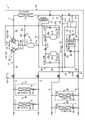
- FIG. 1 is a piping system diagram showing the configuration of a refrigeration system according to Embodiment 1.
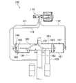
- FIG. 2 is a block diagram showing a configuration of a controller of the heat source unit of Embodiment 1.
- FIG. 3 is a cross-sectional view showing the configuration of the four-way switching valve.
- FIG. 4 is a view corresponding to FIG. 1 showing the flow of refrigerant in cooling operation.
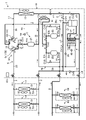
- FIG. 5 is a view corresponding to FIG. 1 showing the flow of refrigerant in the first heating operation.
- FIG. 6 is a view corresponding to FIG. 1 showing the flow of refrigerant in the second heating operation.
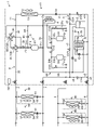
- FIG. 7 is a view corresponding to FIG. 1 showing the flow of refrigerant in the third heating operation.
- FIG. 1 is a piping system diagram showing the configuration of a refrigeration system according to Embodiment 1.
- FIG. 2 is a block diagram showing a configuration of a controller of the heat source unit of Embodiment 1.
- FIG. 3 is
- FIG. 8 is a flow chart showing the operation of the operation switching section of the controller of the first embodiment.
- FIG. 9 is a piping system diagram showing the configuration of a refrigeration system of a modification of the first embodiment.
- FIG. 10 is a piping system diagram showing the configuration of the refrigeration system of Embodiment 2.
- FIG. 11 is a flow chart showing the operation of the operation switching section of the controller of the second embodiment.
- Embodiment 1 will be described.
- the refrigeration system (1) of the present embodiment can cool an object to be cooled and air-condition the room.
- the object to be cooled includes the air in facilities such as refrigerators, freezers, and showcases.
- the refrigerator (1) includes a heat source unit (10) installed outdoors, an air conditioning unit (50) for air conditioning the room, and a cooling unit (60) for cooling the air inside the refrigerator.
- a refrigerating apparatus (1) of this embodiment includes one heat source unit (10), a plurality of cooling units (60), and a plurality of air conditioning units (50).
- the number of cooling units (60) or air conditioning units (50) included in the refrigeration system (1) may be one.
- a heat source unit (10), a cooling unit (60), an air conditioning unit (50), and connecting pipes (2, 3, 4, 60) connecting these units (10, 50, 60) 5) constitutes a refrigerant circuit (6).
- a refrigeration cycle is performed by circulating the refrigerant.
- the refrigerant in the refrigerant circuit (6) of the present embodiment is carbon dioxide.
- the refrigerant circuit (6) is configured to perform a refrigeration cycle in which the high pressure is equal to or higher than the critical pressure of the refrigerant.
- the plurality of air conditioning units (50) are connected to the heat source unit (10) via the first liquid communication pipe (2) and the first gas communication pipe (3). In the refrigerant circuit (6), the plurality of air conditioning units (50) are connected in parallel with each other.
- the plurality of cooling units (60) are connected to the heat source unit (10) via the second liquid communication pipe (4) and the second gas communication pipe (5). In the refrigerant circuit (6), the plurality of cooling units (60) are connected in parallel with each other.
- the heat source unit (10) has an outdoor fan (12) and an outdoor circuit (11).
- the outdoor circuit (11) includes a compression element (C), a flow path switching mechanism (30), an outdoor heat exchanger (13), an outdoor expansion valve (14), a gas-liquid separator (15), a supercooling heat exchanger ( 16), an intercooler (17), and a bypass pipe (85).
- the heat source unit (10) also has a controller (101).
- Compression element (C) compresses the refrigerant.
- the compression element (C) has a high stage compressor (21), a first low stage compressor (23) and a second low stage compressor (22).
- the high-stage compressor (21), the first low-stage compressor (23), and the second low-stage compressor (22) are rotary compressors whose compression mechanisms are driven by motors.
- the high-stage compressor (21), the first low-stage compressor (23), and the second low-stage compressor (22) are configured as variable displacement compressors in which the rotation speed of the compression mechanism can be changed.
- the compression element (C) performs two-stage compression.
- the first low-stage compressor (23) compresses refrigerant sucked from the air conditioning unit (50) or the outdoor heat exchanger (13).
- the second low-stage compressor (22) compresses refrigerant sucked from the cooling unit (60).
- the high stage compressor (21) sucks and compresses the refrigerant discharged from the first low stage compressor (23) and the refrigerant discharged from the second low stage compressor (22).
- a high-stage suction pipe (21a) and a high-stage discharge pipe (21b) are connected to the high-stage compressor (21).
- the high-stage discharge pipe (21b) is a discharge pipe through which refrigerant discharged from the high-stage compressor (21) flows.
- a first low-stage suction pipe (23a) and a first low-stage discharge pipe (23b) are connected to the first low-stage compressor (23).
- the first low-stage suction pipe (23a) is a suction pipe through which refrigerant sucked into the first low-stage compressor (23) flows.
- a second low-stage suction pipe (22a) and a second low-stage discharge pipe (22b) are connected to the second low-stage compressor (22).
- the first low-stage discharge pipe (23b) and the second low-stage discharge pipe (22b) are connected to the high-stage suction pipe (21a).
- the second low-stage suction pipe (22a) is connected to the second gas communication pipe (5).
- the second low-stage compressor (22) communicates with the cooling unit (60) through a second gas communication pipe (5).
- the first low-stage suction pipe (23a) communicates with the air conditioning unit (50) via the flow path switching mechanism (30) and the first gas communication pipe (3).
- the compression element (C) includes a first low-stage pipe (24c) and a second low-stage pipe (24b).
- the first low-stage pipe (24c) is a pipe for bypassing the first low-stage compressor (23) to flow refrigerant.
- the first low-stage pipe (24c) has one end connected to the first low-stage suction pipe (23a) and the other end connected to the first low-stage discharge pipe (23b).
- the first low stage pipe (24c) is provided in parallel with the first low stage compressor (23).
- the second low-stage pipe (24b) is a pipe for bypassing the second low-stage compressor (22) to flow refrigerant.
- the second low-stage pipe (24b) has one end connected to the second low-stage suction pipe (22a) and the other end connected to the second low-stage discharge pipe (22b).
- the second low stage pipe (24b) is provided in parallel with the second low stage compressor (22).
- the flow path switching mechanism (30) is a mechanism for switching the refrigerant flow path in the refrigerant circuit (6).
- the channel switching mechanism (30) includes a first pipe (31), a second pipe (32), a third pipe (33), a fourth pipe (34), a first switching valve (81), and a second switching valve. (82).
- the inflow end of the first pipe (31) and the inflow end of the second pipe (32) are connected to the high-stage discharge pipe (21b).
- the outflow end of the third pipe (33) and the outflow end of the fourth pipe (34) are connected to the first low-stage suction pipe (23a).
- Each of the first switching valve (81) and the second switching valve (82) defines a flow path for refrigerant drawn into the first low-stage compressor (23) and a flow path for refrigerant discharged from the high-stage compressor (21). switch between distribution channels.
- the first switching valve (81) and the second switching valve (82) are composed of a four-way switching valve (150).
- the four-way switching valve (150) used as the first switching valve (81) and the second switching valve (82) will be described later in detail.
- the first port of the first switching valve (81) is connected to the outflow end of the first pipe (31).
- a second port of the first switching valve (81) is connected to an inflow end of the third pipe (33).
- a third port of the first switching valve (81) is sealed.
- a fourth port of the first switching valve (81) is connected to one end of the first outdoor gas pipe (35).
- the other end of the first outdoor gas pipe (35) is connected to the first gas communication pipe (3).
- the first port of the second switching valve (82) is connected to the outflow end of the second pipe (32).
- a second port of the second switching valve (82) is connected to the inflow end of the fourth pipe (34).
- a third port of the second switching valve (82) is connected to the second outdoor gas pipe (36).
- a fourth port of the second switching valve (82) is sealed.
- Each of the first switching valve (81) and the second switching valve (82) switches between a first state (a state indicated by a solid line in FIG. 1) and a second state (a state indicated by a broken line in FIG. 1).
- the first port communicates with the third port and the second port communicates with the fourth port.
- the first port communicates with the fourth port, and the second port communicates with the third port.
- the outdoor heat exchanger (13) constitutes a heat source heat exchanger.
- the outdoor heat exchanger (13) is a fin-and-tube air heat exchanger.
- the outdoor fan (12) is arranged near the outdoor heat exchanger (13).
- the outdoor fan (12) conveys outdoor air.
- the outdoor heat exchanger (13) exchanges heat between refrigerant flowing therein and outdoor air carried by the outdoor fan (12).
- a second outdoor gas pipe (36) is connected to the gas end of the outdoor heat exchanger (13).
- An outdoor flow path (O) is connected to the liquid end of the outdoor heat exchanger (13).
- the outdoor flow path (O) consists of the first outdoor pipe (o1), the second outdoor pipe (o2), the third outdoor pipe (o3), the fourth outdoor pipe (o4), the fifth outdoor pipe (o5), the 6 tube (o6), outdoor 7th tube (o7) and outdoor 8th tube (o8).
- One end of the first outdoor pipe (o1) is connected to the liquid end of the outdoor heat exchanger (13).
- One end of the second outdoor pipe (o2) and one end of the third outdoor pipe (o3) are connected to the other end of the first outdoor pipe (o1).
- the other end of the second outdoor pipe (o2) is connected to the top of the gas-liquid separator (15).
- One end of the fourth outdoor pipe (o4) is connected to the bottom of the gas-liquid separator (15).
- One end of the fifth outdoor pipe (o5) and the other end of the third outdoor pipe (o3) are connected to the other end of the fourth outdoor pipe (o4).
- One end of the sixth outdoor pipe (o6) and one end of the eighth outdoor pipe (o8) are connected to the other end of the fifth outdoor pipe (o5).
- the other end of the outdoor eighth pipe (o8) is connected to the first liquid side main pipe (4a) of the second liquid connection pipe (4).
- the eighth outdoor pipe (o8) is a liquid pipe through which the liquid refrigerant downstream of the gas-liquid separator (15) flows.
- the other end of the sixth outdoor pipe (o6) is connected to the first liquid connection pipe (2).
- One end of the seventh outdoor pipe (o7) is connected to the middle of the sixth outdoor pipe (o6).
- the other end of the seventh outdoor pipe (o7) is connected to the middle of the second outdoor pipe (o2).
- the first outdoor pipe (o1) of the outdoor circuit (11) is provided with an outdoor expansion valve (14).
- the outdoor expansion valve (14) is an electronic expansion valve whose degree of opening is adjustable.
- the gas-liquid separator (15) constitutes a container that stores refrigerant.
- the gas-liquid separator (15) is provided downstream of the outdoor expansion valve (14).
- the gas-liquid separator (15) separates the refrigerant into gas refrigerant and liquid refrigerant.
- the top of the gas-liquid separator (15) is connected to the other end of the second outdoor pipe (o2) and one end of a later-described gas vent pipe (37).
- the outdoor circuit (11) has an intermediate injection circuit (49).
- the intermediate injection circuit (49) is a circuit that supplies refrigerant decompressed by the outdoor expansion valve (14) to the high stage suction pipe (21a).
- the intermediate injection circuit (49) comprises a vent tube (37) and an injection tube (38).
- the injection pipe (38) is connected to the middle of the fifth outdoor pipe (o5).
- the other end of the injection pipe (38) is connected to the high-stage suction pipe (21a).
- the injection pipe (38) is provided with a pressure reducing valve (40).
- the pressure reducing valve (40) is an expansion valve with a variable opening.
- the gas vent pipe (37) is a pipe for sending the gas refrigerant of the gas-liquid separator (15) to the high-stage suction pipe (21a). Specifically, one end of the gas vent pipe (37) is connected to the top of the gas-liquid separator (15). The other end of the gas vent pipe (37) is connected to the middle of the injection pipe (38). A gas vent valve (39) is connected to the gas vent pipe (37).
- the gas vent valve (39) is an electronic expansion valve with a variable degree of opening.
- the outdoor circuit (11) has a subcooling heat exchanger (16).
- the supercooling heat exchanger (16) is a heat exchanger that cools the refrigerant (mainly liquid refrigerant) separated by the gas-liquid separator (15).
- a subcooling heat exchanger (16) is provided downstream of the gas-liquid separator (15).
- the subcooling heat exchanger (16) has a first flow path (16a) and a second flow path (16b). The subcooling heat exchanger (16) exchanges heat between the refrigerant flowing through the first flow path (16a) and the refrigerant flowing through the second flow path (16b).
- the subcooling heat exchanger (16) cools the refrigerant flowing through the first flow path (16a).
- the first flow path (16a) is connected in the middle of the fourth outdoor pipe (o4), which is a liquid pipe through which the liquid refrigerant of the outdoor circuit (11) flows.
- the second flow path (16b) is included in the intermediate injection circuit (49). Specifically, the second flow path (16b) is connected to the injection pipe (38) downstream of the pressure reducing valve (40). Refrigerant pressure-reduced by the pressure-reducing valve (40) flows through the second flow path (16b).
- the intercooler (17) is connected to the intermediate flow path (41).
- One end of the intermediate flow path (41) is connected to the first low-stage discharge pipe (23b) and the second low-stage discharge pipe (22b).
- the other end of the intermediate flow path (41) is connected to the high-stage suction pipe (21a).
- the intercooler (17) is a fin and tube type air heat exchanger.
- a blower fan (17a) is arranged near the intercooler (17).
- the intercooler (17) exchanges heat between the refrigerant flowing therein and the outdoor air carried by the blower fan (17a).
- the outdoor circuit (11) includes a first check valve (CV1), a second check valve (CV2), a third check valve (CV3), a fourth check valve (CV4), a fifth check valve (CV5 ), a sixth check valve (CV6), a seventh check valve (CV7), an eighth check valve (CV8), and a ninth check valve (CV9).
- These check valves (CV1 to CV9) allow the flow of refrigerant in the direction of the arrows shown in FIG. 1 and prohibit the flow of refrigerant in the direction opposite to the arrows.
- the first check valve (CV1) is connected to the high-stage discharge pipe (21b).
- the second check valve (CV2) is connected to the second low stage discharge pipe (22b).
- the third check valve (CV3) is connected to the first low stage discharge pipe (23b).
- the fourth check valve (CV4) is connected to the second outdoor pipe (o2).
- the fifth check valve (CV5) is connected to the third outdoor pipe (o3).
- the sixth check valve (CV6) is connected to the sixth outdoor pipe (o6).
- the seventh check valve (CV7) is connected to the seventh outdoor pipe (o7).
- the eighth check valve (CV8) is connected to the second low-stage pipe (24b).
- the ninth check valve (CV9) is connected to the first low-stage pipe (24c).
- the heat source unit (10) has various sensors.
- the various sensors include a high pressure sensor (71), an intermediate pressure sensor (72), a first low pressure sensor (73), a second low pressure sensor (74), and a liquid refrigerant pressure sensor (75).
- the high-pressure sensor (71) detects the pressure of the refrigerant discharged from the high-stage compressor (21) (high-pressure refrigerant pressure (HP)).
- the intermediate pressure sensor (72) detects the pressure of the refrigerant in the intermediate flow path (41), in other words, the pressure of the high-stage compressor (21), the second low-stage compressor (22), and the first low-stage compressor (23). ) to detect the pressure of the refrigerant (pressure of the intermediate pressure refrigerant (MP)).
- the first low-pressure pressure sensor (73) detects the pressure of refrigerant sucked into the second low-stage compressor (22) (first low-pressure refrigerant pressure (LP1)).
- the second low-pressure sensor (74) detects the pressure of refrigerant drawn into the first low-stage compressor (23) (second low-pressure refrigerant pressure (LP2)).
- the liquid refrigerant pressure sensor (75) detects the liquid refrigerant pressure (liquid refrigerant pressure (RP)) in the gas-liquid separator (15).
- the bypass pipe (85) has one end connected to the high-stage discharge pipe (21b) and the other end connected to the first low-stage suction pipe (23a).
- a control valve (86) is provided in the bypass pipe (85).
- the control valve (86) is an electrically operated valve whose degree of opening can be adjusted.
- the controller (101) comprises a microcomputer (102) mounted on the control board and a memory device (105) storing software for operating the microcomputer (102). include.
- the memory device (105) is a semiconductor memory.
- a controller (101) controls components of the heat source unit (10).
- the microcomputer (102) of the controller (101) functions as an operation selection section (103) and an operation switching section (104) by executing programs stored in the memory device (105).
- An operation selection unit (103) selects an operation to be executed by the refrigeration system (1) from cooling operation, first heating operation, second heating operation, third heating operation, and defrosting operation, which will be described later.
- the operation switching unit (104) controls components of the refrigeration system (1) to cause the refrigeration system (1) to perform the operation selected by the operation selection unit (103).
- the air conditioning unit (50) is the first usage unit installed indoors.
- the air conditioning unit (50) air-conditions the indoor space.
- the air conditioning unit (50) has an indoor fan (52) and an indoor circuit (51).
- a liquid end of the indoor circuit (51) is connected to the first liquid communication pipe (2).
- a first gas communication pipe (3) is connected to the gas end of the indoor circuit (51).
- the indoor circuit (51) is provided with an indoor expansion valve (53) and an indoor heat exchanger (54) in order from the liquid end to the gas end.
- the indoor expansion valve (53) is an electronic expansion valve with a variable opening.
- the indoor heat exchanger (54) is a fin-and-tube air heat exchanger.
- the indoor fan (52) is arranged near the indoor heat exchanger (54).
- the indoor fan (52) conveys indoor air.
- the indoor heat exchanger (54) exchanges heat between the refrigerant flowing therein and the indoor air conveyed by the indoor fan (52).
- the cooling unit (60) is a second usage unit installed indoors.
- the cooling unit (60) is, for example, a refrigerated showcase installed in a store such as a convenience store.
- the cooling unit (60) may be a unit cooler that cools the air inside the refrigerator.
- the cooling unit (60) has a cooling fan (62) and a cooling circuit (61).
- a liquid side branch pipe (4c) of the second liquid communication pipe (4) is connected to the liquid end of the cooling circuit (61).
- a gas side branch pipe (5c) of the second gas communication pipe (5) is connected to the gas end of the cooling circuit (61).
- the cooling circuit (61) is provided with a cooling expansion valve (63) and a cooling heat exchanger (64) in order from the liquid end to the gas end.
- the cooling expansion valve (63) is an electronic expansion valve with a variable opening.
- the cooling heat exchanger (64) is a fin-and-tube air heat exchanger.
- the cooling fan (62) is arranged near the cooling heat exchanger (64). The cooling fan (62) conveys the air inside the warehouse.
- the cooling heat exchanger (64) exchanges heat between the refrigerant flowing therein and the indoor air conveyed by the cooling fan (62).
- the four-way switching valve (150) includes a valve body (160) and a pilot valve (170).
- the four-way switching valve (150) is configured to operate using refrigerant pressure.
- the valve body (160) includes one cylinder portion (161), one valve body (162), and two pistons (163).
- the cylinder part (161) is a cylindrical member with both ends closed.
- the valve body (162) is housed inside the cylinder portion (161) and is slidable in the axial direction of the cylinder portion (161).
- the pistons (163) are arranged one each on one end side and the other end side of the cylinder portion (161).
- the two pistons (163) are connected to the valve body (162).
- the internal space of the cylinder part (161) is divided into a first chamber (166), a second chamber (167) and a central chamber (165) by two pistons (163).
- the first chamber (166) is located on one end side (the left end side in FIG. 3) of the cylinder portion (161).
- the second chamber (167) is located on the other end side (right end side in FIG. 3) of the cylinder portion (161).
- the central chamber (165) is the space between the two pistons (163).
- the valve body (162) is arranged in this central chamber (165). The pressure of the central chamber (165) is introduced into the first chamber (166) and the second chamber (167) through a bleed hole formed in the piston (163).
- the cylinder portion (161) is provided with a first port (151), a second port (152), a third port (153) and a fourth port (154).
- the first port (151) is formed in the axial center of the cylinder portion (161).
- the second port (152), the third port (153), and the fourth port (154) are arranged in a row along the longitudinal direction of the cylinder portion (161) at positions facing the first port (151). .
- the valve body (162) is provided to face the open ends of the second port (152), the third port (153) and the fourth port (154).
- the pilot valve (170) is a solenoid valve.
- the first pipe (171), the second pipe (172) and the low pressure pipe (173) are connected to the pilot valve (170).
- the first pipe (171) is connected to one end of the cylinder portion (161) and communicates with the first chamber (166).
- the second pipe (172) is connected to the other end of the cylinder portion (161) and communicates with the second chamber (167).
- the low pressure pipe (173) is connected to the second port (152).
- the pilot valve (170) switches between an OFF state in which the solenoid is not energized and an ON state in which the solenoid is energized.
- the pilot valve (170) in the OFF state connects the first pipe (171) to the low pressure pipe (173) and disconnects the second pipe (172) from the low pressure pipe (173).
- the ON-state pilot valve (170) disconnects the first pipe (171) from the low-pressure pipe (173) and communicates the second pipe (172) with the low-pressure pipe (173).
- the four-way switching valve (150) switches between the first state and the second state by intermittently energizing the pilot valve (170).
- the four-way switching valve (150) When the pilot valve (170) is turned off, the four-way switching valve (150) is in the first state.
- the first pipe (171) communicates with the low pressure pipe (173) and the first chamber (166) has a lower pressure than the second chamber (167).
- the valve body (162) is located closer to the first chamber (166) and communicates the second port (152) with the fourth port (154).
- the first port (151) communicates with the third port (153) through the central chamber (165).
- the four-way switching valve (150) When the pilot valve (170) is turned on, the four-way switching valve (150) is in the second state.
- the second pipe (172) communicates with the low pressure pipe (173) and the second chamber (167) has a lower pressure than the first chamber (166).
- the valve body (162) is located closer to the second chamber (167) and communicates the second port (152) with the third port (153).
- the first port (151) communicates with the fourth port (154) through the central chamber (165).
- a refrigeration system (1) performs a cooling operation, a first heating operation, a second heating operation, and a third heating operation.
- the refrigeration system (1) also performs a defrost operation to melt frost adhered to the outdoor heat exchanger (13).
- the cooling operation of the refrigeration system (1) will be described with reference to FIG.
- the cooling operation is an operation in which the air conditioning unit (50) cools the room.
- the first switching valve (81) and the second switching valve (82) are set to the first state.
- the first low-stage compressor (23), the second low-stage compressor (22), and the high-stage compressor (21) operate.
- a refrigeration cycle is performed by circulating the refrigerant in the refrigerant circuit (6), the outdoor heat exchanger (13) functions as a radiator (gas cooler), and the cooling heat exchanger (64) and indoor heat exchange A vessel (54) functions as an evaporator.
- the refrigerant discharged from the high-stage compressor (21) passes through the second switching valve (82), flows into the outdoor heat exchanger (13), and radiates heat to the outdoor air. After passing through the outdoor heat exchanger (13), the refrigerant is decompressed when passing through the outdoor expansion valve (14), then passes through the gas-liquid separator (15), and then into the subcooling heat exchanger (16). It is cooled while passing through the first flow path (16a). Part of the refrigerant that has passed through the first flow path (16a) of the subcooling heat exchanger (16) passes through the injection pipe (38) to the second flow path (16b) of the subcooling heat exchanger (16). It flows in, absorbs heat, evaporates, and then flows into the high-stage suction pipe (21a). The rest of the refrigerant that has passed through the first flow path (16a) of the subcooling heat exchanger (16) is divided into the first liquid communication pipe (2) and the second liquid communication pipe (4) and flows into them.
- the refrigerant flowing through the first liquid communication pipe (2) is distributed to multiple air conditioning units (50).
- each air conditioning unit (50) the refrigerant that has flowed into the indoor circuit (51) is decompressed when passing through the indoor expansion valve (53), then absorbs heat from the indoor air in the indoor heat exchanger (54) and evaporates. do.
- Each air conditioning unit (50) blows out the air cooled in the indoor heat exchanger (54) into the indoor space.
- the refrigerant flowing out from the indoor heat exchanger (54) of each air conditioning unit (50) flows into the first gas communication pipe (3) and joins, and then flows into the first outdoor gas pipe (35) of the outdoor circuit (11). Then, it flows through the first switching valve (81) into the first low-stage suction pipe (23a), then is drawn into the first low-stage compressor (23) and compressed.
- the refrigerant flowing through the second liquid communication pipe (4) is distributed to multiple cooling units (60).
- each cooling unit (60) the refrigerant that has flowed into the cooling circuit (61) is decompressed when passing through the cooling expansion valve (63), and then absorbs heat from the inside air in the cooling heat exchanger (64). Evaporate.
- Each cooling unit (60) blows out the air cooled in the cooling heat exchanger (64) into the interior space.
- the refrigerant flowing out of the cooling heat exchanger (64) of each cooling unit (60) flows into the second gas communication pipe (5) and joins the second low-stage suction pipe (22a) of the outdoor circuit (11). and then sucked into and compressed by the second low-stage compressor (22).
- the refrigerant compressed in each of the first low-stage compressor (23) and the second low-stage compressor (22) radiates heat to the outdoor air in the intercooler (17) and flows through the injection pipe (38). After joining, it is sucked into the high-stage compressor (21).
- the high-stage compressor (21) compresses the sucked refrigerant and discharges it.
- the first heating operation of the refrigeration system (1) will be described with reference to FIG.
- the first heating operation is an operation in which the air conditioning unit (50) heats the room.
- the first heating operation is performed in an operating state in which the amount of heat released by the refrigerant in the air conditioning unit (50) is less than the amount of heat absorbed by the refrigerant in the cooling unit (60).
- the first switching valve (81) is set to the second state, and the second switching valve (82) is set to the first state. Further, in the first heating operation, the first low-stage compressor (23) is deactivated, and the second low-stage compressor (22) and the high-stage compressor (21) are operated. In the first heating operation, a refrigeration cycle is performed by circulating the refrigerant in the refrigerant circuit (6), and the indoor heat exchanger (54) and the outdoor heat exchanger (13) function as radiators (gas coolers) to provide cooling.
- a heat exchanger (64) functions as an evaporator.
- Part of the refrigerant discharged from the high-stage compressor (21) passes through the first switching valve (81) and flows into the first outdoor gas pipe (35), and the rest passes through the second switching valve (82). and flows into the second outdoor gas pipe (36).
- the refrigerant flowing through the first outdoor gas pipe (35) is distributed to the plurality of air conditioning units (50) through the first gas communication pipe (3).
- each air conditioning unit (50) the refrigerant that has flowed into the indoor circuit (51) radiates heat to the indoor air in the indoor heat exchanger (54). It flows into the first fluid communication pipe (2).
- Refrigerant that has flowed from each air conditioning unit (50) into the first liquid connection pipe (2) flows into the gas-liquid separator (15) of the outdoor circuit (11).
- Each air conditioning unit (50) blows out the air heated in the indoor heat exchanger (54) into the indoor space.
- the refrigerant flowing through the second outdoor gas pipe (36) flows into the outdoor heat exchanger (13) and releases heat to the outdoor air. After passing through the outdoor heat exchanger (13), the refrigerant flows into the gas-liquid separator (15) after being decompressed while passing through the outdoor expansion valve (14).
- the refrigerant that has flowed out of the gas-liquid separator (15) is cooled while passing through the first flow path (16a) of the supercooling heat exchanger (16).
- Part of the refrigerant that has passed through the first flow path (16a) of the subcooling heat exchanger (16) passes through the injection pipe (38) to the second flow path (16b) of the subcooling heat exchanger (16). It flows in, absorbs heat, evaporates, and then flows into the high-stage suction pipe (21a).
- the rest of the refrigerant that has passed through the first flow path (16a) of the supercooling heat exchanger (16) flows into the second liquid communication pipe (4).
- the refrigerant flowing through the second liquid communication pipe (4) is distributed to multiple cooling units (60).
- each cooling unit (60) the refrigerant that has flowed into the cooling circuit (61) is decompressed when passing through the cooling expansion valve (63), and then absorbs heat from the inside air in the cooling heat exchanger (64). Evaporate.
- Each cooling unit (60) blows out the air cooled in the cooling heat exchanger (64) into the interior space.
- the refrigerant flowing out of the cooling heat exchanger (64) of each cooling unit (60) flows into the second gas communication pipe (5) and joins the second low-stage suction pipe (22a) of the outdoor circuit (11). and then sucked into and compressed by the second low-stage compressor (22).
- the refrigerant compressed in the second low-stage compressor (22) releases heat to the outdoor air in the intercooler (17), joins the refrigerant flowing through the injection pipe (38), and then flows into the high-stage compressor (21). inhaled.
- the high-stage compressor (21) compresses the sucked refrigerant and discharges it.
- the second heating operation of the refrigeration system (1) will be described with reference to FIG.
- the second heating operation is an operation in which the air conditioning unit (50) heats the room.
- the second heating operation is performed in an operating state in which the amount of heat released by the refrigerant in the air conditioning unit (50) is balanced with the amount of heat absorbed by the refrigerant in the cooling unit (60).
- the first switching valve (81) and the second switching valve (82) are set to the second state.
- the first low-stage compressor (23) is deactivated, and the second low-stage compressor (22) and the high-stage compressor (21) are operated.
- a refrigeration cycle is performed by circulating the refrigerant in the refrigerant circuit (6), the indoor heat exchanger (54) functions as a radiator (gas cooler), and the cooling heat exchanger (64) evaporates.
- the outdoor heat exchanger (13) is deactivated.
- Refrigerant discharged from the high-stage compressor (21) passes through the first switching valve (81), flows into the first outdoor gas pipe (35), and then flows through the first gas communication pipe (3) to a plurality of air conditioning units (50).
- each air conditioning unit (50) the refrigerant that has flowed into the indoor circuit (51) radiates heat to the indoor air in the indoor heat exchanger (54). It flows into the first fluid communication pipe (2).
- Refrigerant that has flowed from each air conditioning unit (50) into the first liquid connection pipe (2) flows into the gas-liquid separator (15) of the outdoor circuit (11).
- Each air conditioning unit (50) blows out the air heated in the indoor heat exchanger (54) into the indoor space.
- the refrigerant that has flowed out of the gas-liquid separator (15) is cooled while passing through the first flow path (16a) of the supercooling heat exchanger (16).
- Part of the refrigerant that has passed through the first flow path (16a) of the subcooling heat exchanger (16) passes through the injection pipe (38) to the second flow path (16b) of the subcooling heat exchanger (16). It flows in, absorbs heat, evaporates, and then flows into the high-stage suction pipe (21a).
- the rest of the refrigerant that has passed through the first flow path (16a) of the supercooling heat exchanger (16) flows into the second liquid communication pipe (4).
- the refrigerant flowing through the second liquid communication pipe (4) is distributed to multiple cooling units (60).
- each cooling unit (60) the refrigerant that has flowed into the cooling circuit (61) is decompressed when passing through the cooling expansion valve (63), and then absorbs heat from the inside air in the cooling heat exchanger (64). Evaporate.
- Each cooling unit (60) blows out the air cooled in the cooling heat exchanger (64) into the interior space.
- the refrigerant flowing out of the cooling heat exchanger (64) of each cooling unit (60) flows into the second gas communication pipe (5) and joins the second low-stage suction pipe (22a) of the outdoor circuit (11). and then sucked into and compressed by the second low-stage compressor (22).
- the refrigerant compressed in the second low-stage compressor (22) releases heat to the outdoor air in the intercooler (17), joins the refrigerant flowing through the injection pipe (38), and then flows into the high-stage compressor (21). inhaled.
- the high-stage compressor (21) compresses the sucked refrigerant and discharges it.
- the third heating operation of the refrigeration system (1) will be described with reference to FIG.
- the third heating operation is an operation in which the air conditioning unit (50) heats the room.
- the third heating operation is performed in an operating state in which the amount of heat released by the refrigerant in the air conditioning unit (50) is greater than the amount of heat absorbed by the refrigerant in the cooling unit (60).
- the first switching valve (81) and the second switching valve (82) are set to the second state. Further, in the third heating operation, the first low-stage compressor (23), the second low-stage compressor (22), and the high-stage compressor (21) operate.
- a refrigeration cycle is performed by circulating the refrigerant in the refrigerant circuit (6), the indoor heat exchanger (54) functions as a radiator (gas cooler), and the cooling heat exchanger (64) and the outdoor heat exchanger (64)
- a heat exchanger (13) functions as an evaporator.
- Refrigerant discharged from the high-stage compressor (21) passes through the first switching valve (81), flows into the first outdoor gas pipe (35), and then flows through the first gas communication pipe (3) to a plurality of air conditioning units (50).
- each air conditioning unit (50) the refrigerant that has flowed into the indoor circuit (51) radiates heat to the indoor air in the indoor heat exchanger (54). It flows into the first fluid communication pipe (2).
- Refrigerant that has flowed from each air conditioning unit (50) into the first liquid connection pipe (2) flows into the gas-liquid separator (15) of the outdoor circuit (11).
- Each air conditioning unit (50) blows out the air heated in the indoor heat exchanger (54) into the indoor space.
- the refrigerant that has flowed out of the gas-liquid separator (15) is cooled while passing through the first flow path (16a) of the supercooling heat exchanger (16).
- the refrigerant that has passed through the first flow path (16a) of the subcooling heat exchanger (16) branches and flows into the fifth outdoor pipe (o5) and the third outdoor pipe (o3).
- the refrigerant flowing through the eighth outdoor pipe (o8) is distributed to the plurality of cooling units (60) through the second liquid communication pipe (4).
- each cooling unit (60) the refrigerant that has flowed into the cooling circuit (61) is decompressed when passing through the cooling expansion valve (63), and then absorbs heat from the inside air in the cooling heat exchanger (64). Evaporate.
- Each cooling unit (60) blows out the air cooled in the cooling heat exchanger (64) into the interior space.
- the refrigerant flowing out of the cooling heat exchanger (64) of each cooling unit (60) flows into the second gas communication pipe (5) and joins the second low-stage suction pipe (22a) of the outdoor circuit (11). and then sucked into and compressed by the second low-stage compressor (22).
- the refrigerant flowing through the third outdoor pipe (o3) is depressurized when passing through the outdoor expansion valve (14), flows into the outdoor heat exchanger (13), absorbs heat from the outdoor air, and evaporates. After passing through the outdoor heat exchanger (13), the refrigerant passes through the second switching valve (82), flows into the first low-stage suction pipe (23a), and is then sucked into the first low-stage compressor (23). compressed.
- the refrigerant compressed in each of the first low-stage compressor (23) and the second low-stage compressor (22) radiates heat to the outdoor air in the intercooler (17) and flows through the injection pipe (38). After joining, it is sucked into the high-stage compressor (21).
- the high-stage compressor (21) compresses the sucked refrigerant and discharges it.
- the defrost operation of the refrigerator (1) is an operation for melting frost adhering to the outdoor heat exchanger (13).
- frost on the outdoor heat exchanger (13) reaches a certain level or more during the third heating operation, the refrigeration system (1) temporarily suspends the third heating operation and performs a defrost operation.
- refrigerant flows in the refrigerant circuit (6) in the same manner as in the first heating operation.
- the second switching valve (82) is set to the first state, and the outdoor heat exchanger (13) functions as a radiator (gas cooler). Frost adhering to the outdoor heat exchanger (13) is warmed by the refrigerant and melted.
- controller The operation performed by the operation switching section (104) of the controller (101) will be described. As described above, the operation switching unit (104) controls the components of the refrigeration system (1) to cause the refrigeration system (1) to perform the operation selected by the operation selection unit (103).
- the operation switching unit (104) operates the first switching valve (81) and the second switching valve (82) in order to change the operation performed by the refrigeration system (1). For example, when switching the operation of the refrigeration system (1) from the cooling operation to the first heating operation, the operation switching section (104) switches the first switching valve (81) from the first state to the second state. conduct. When switching the operation of the refrigeration system (1) from the first heating operation to the second heating operation, the operation switching section (104) switches the second switching valve (82) from the first state to the second state. take action. When the operation of the refrigeration system (1) is switched from the third heating operation to the defrost operation, the operation switching section (104) switches the second switching valve (82) from the second state to the first state. conduct.
- the operation switching section (104) switches the four-way switching valve (150) constituting the first switching valve (81) and the second switching valve (82) from one of the first state and the second state to the other as shown in FIG.
- the switching operation shown in the flow chart of No. 8 is performed.
- Step ST10 the operation switching section (104) determines whether or not the first low stage compressor (23) is in operation.
- the operation switching section (104) performs the process of step ST11 to stop the first low stage compressor (23).
- the operation switching section (104) performs the processing of step ST12.
- the operation switching section (104) skips the process of step ST11 and performs the process of step ST12.
- Step ST12> In the process of step ST12, the operation switching section (104) reduces the operating frequency of the high stage compressor (21). As a result, the rotational speed of the high-stage compressor (21) decreases.
- the rotation speed of the high-stage compressor (21) decreases, the mass flow rate of refrigerant discharged from the high-stage compressor (21) decreases, and the high pressure of the refrigeration cycle decreases.
- the high pressure of the refrigeration cycle is substantially equal to the pressure of refrigerant flowing through the high-stage discharge pipe (21b). Therefore, when the rotational speed of the high-stage compressor (21) decreases, the four-way switching valve (150) constituting the first switching valve (81) and the second switching valve (82) causes the high-stage discharge pipe (21b) to rotate. The difference between the refrigerant pressure in the connected first port (151) and the refrigerant pressure in the second port (152) connected to the first low-stage suction pipe (23a) is reduced.
- Step ST13 the operation switching section (104) performs the process of step ST13.
- the operation switching section (104) opens the fully closed control valve (86) to gradually increase the degree of opening of the control valve (86) to a predetermined degree of opening.
- the operation switching section (104) performs the process of step ST14.
- the operation switching section (104) switches the four-way switching valve (150) which constitutes the one of the first switching valve (81) and the second switching valve (82) that needs to be switched. It outputs an instruction signal to operate the four-way switching valve (150).
- the operation switching unit (104) instructs a signal for switching the energization of the pilot valve (170) of the four-way switching valve (150), which is the output target of the instruction signal, from one of the ON state and the OFF state to the other. output as a signal.
- the four-way switching valve (150) that has received the instruction signal switches from one of the first state and the second state to the other.
- the operation switching section (104) switches the first switching valve (81) and the second switching valve (82) in a state where the first low-stage compressor (23) is stopped and the high-stage compressor (21) is in operation. ), an instruction signal is output to the four-way switching valve (150).
- the operation switching section (104) also reduces the rotation speed of the high stage compressor (21), opens the control valve (86), and then outputs an instruction signal to the four-way switching valve (150).
- the operation switching section (104) reduces the difference in refrigerant pressure between the first port (151) and the second port (152) of the four-way switching valve (150), and then switches the four-way switching valve (150). output an instruction signal. Therefore, the load acting on the valve body (162) and the piston (163) is reduced when the four-way switching valve (150) is switched, and the impact force generated due to the movement of the valve body (162) and the piston (163). becomes smaller. As a result, damage to the four-way switching valve (150) and damage to the piping connected to the four-way switching valve (150) can be prevented, thereby improving the reliability of the heat source unit (10).
- Step ST15 Subsequently, the operation switching section (104) performs the process of step ST15. In the process of step ST15, the operation switching section (104) returns the control valve (86) to the fully closed state. When the process of step ST15 ends, the operation switching section (104) ends the switching operation.
- the operation switching section (104) of the controller (101) causes the first low-stage compressor (23) to stop and the high-stage compressor (21) to operate. state, the rotation speed of the high-stage compressor (21) is reduced, and after the control valve (86) is opened, the four-way switching valve (150) constituting the first switching valve (81) or the second switching valve (82) is opened. ) to output an instruction signal.
- the operation switching section (104) of the controller (101) of the present embodiment reduces the difference in refrigerant pressure between the first port (151) and the second port (152) of the four-way switching valve (150).
- an instruction signal is output to the four-way switching valve (150). Therefore, the load acting on the valve body (162) and the piston (163) that move during the switching process of the four-way selector valve (150) can be suppressed, resulting in the reduction of the valve body (162) and the piston (163).
- the impact force caused by movement can be kept small. Therefore, according to the present embodiment, damage to the four-way switching valve (150) and damage to the piping connected to the four-way switching valve (150) can be prevented, thereby improving the reliability of the heat source unit (10). can be made
- the channel switching mechanism (30) may be configured as shown in FIG.
- the flow path switching mechanism (30) of the present modification includes a first switching valve (81) and a second switching valve (81) each composed of a four-way switching valve (150). (82) provided.
- a first port of the first switching valve (81) is connected to the high-stage discharge pipe (21b).
- the second port of the first switching valve (81) is connected via piping to the fourth port of the second switching valve (82).
- a third port of the first switching valve (81) is connected to the second outdoor gas pipe (36).
- a fourth port of the first switching valve (81) is connected to the first outdoor gas pipe (35).
- the first port of the second switching valve (82) is connected via piping to the downstream side of the first check valve (CV1) in the high-stage discharge pipe (21b).
- a second port of the second switching valve (82) is connected to the first low-stage suction pipe (23a).
- a third port of the second switching valve (82) is sealed.
- a fourth port of the second switching valve (82) is connected via a pipe to a second port of the first switching valve (81).
- the first switching valve (81) and the second switching valve (82) are respectively in a first state (shown by solid lines in FIG. 1) and a second state. (the state indicated by the dashed line in FIG. 1).
- the first switching valve (81) and the second switching valve (82) are set to the first state.
- the first switching valve (81) and the second switching valve (82) are set to the second state.
- the first switching valve (81) is set to the second state, and the second switching valve (82) is set to the first state.
- the third heating operation the first switching valve (81) is set to the second state, and the second switching valve (82) is set to the first state.
- the cooling unit (60) of the first embodiment is omitted from the refrigeration system (1) of the present embodiment.
- the refrigerant circuit (6) of the refrigeration system (1) of the present embodiment one heat source unit (10) and a plurality of air conditioning units (50) are connected to the first liquid communication pipe (2) and the second gas communication pipe. Connected by (5).
- the second low-stage compressor (22), second low-stage suction pipe (22a), and second low-stage discharge pipe (22b) of Embodiment 1 are omitted.
- the compression element (C) of the present embodiment includes the first low-stage compressor (23) and the high-stage compressor (21), but does not include the second low-stage compressor (22).
- the heat source unit (10) of the present embodiment includes a switching valve (80) instead of the channel switching mechanism (30) of the first embodiment.
- the switching valve (80) like the first switching valve (81) and the second switching valve (82) of the first embodiment, is a four-way switching valve (150).
- the switching valve (80) has a first port connected to the high-stage discharge pipe (21b), a second port connected to the first low-stage suction pipe (23a), a third port connected to the second outdoor gas pipe (36), and a third port connected to the second outdoor gas pipe (36). Four ports are connected to the first outdoor gas pipe (35) respectively.
- the switching valve (80) switches between a first state (a state indicated by a solid line in FIG. 10) and a second state (a state indicated by a broken line in FIG. 10).
- a first state a state indicated by a solid line in FIG. 10
- a second state a state indicated by a broken line in FIG. 10
- the first port communicates with the third port and the second port communicates with the fourth port.
- the switching valve (80) in the second state the first port communicates with the fourth port and the second port communicates with the third port.
- a refrigeration system (1) of the present embodiment performs a cooling operation, a heating operation, and a defrost operation.
- the switching valve (80) In cooling operation, the switching valve (80) is set to the first state.
- the first low-stage compressor (23) and the high-stage compressor (21) operate, and the outdoor heat exchanger (13) functions as a radiator (gas cooler).
- the indoor heat exchanger (54) of the air conditioning unit (50) functions as an evaporator.
- the switching valve (80) is set to the second state.
- the first low-stage compressor (23) and the high-stage compressor (21) are operated, and the indoor heat exchanger (54) of each air conditioning unit (50) is connected to the radiator ( gas cooler), and the outdoor heat exchanger (13) functions as an evaporator.
- the defrost operation is an operation for melting frost adhering to the outdoor heat exchanger (13).
- frost on the outdoor heat exchanger (13) reaches a certain level or more during heating operation, the refrigeration system (1) temporarily suspends heating operation and performs defrost operation.
- the refrigerant flows in the refrigerant circuit (6) in the same way as in the cooling operation.
- the switching valve (80) is set to the first state, and the outdoor heat exchanger (13) functions as a radiator (gas cooler). Frost adhering to the outdoor heat exchanger (13) is warmed by the refrigerant and melted.
- controller The operation performed by the operation switching section (104) of the controller (101) will be described.
- the operation switching unit (104) of the present embodiment switches the components of the refrigeration system (1) to cause the refrigeration system (1) to perform the operation selected by the operation selection unit (103). Control.
- the operation switching unit (104) operates the switching valve (80) to change the operation performed by the refrigeration system (1). For example, when switching the operation of the refrigeration system (1) from the cooling operation to the heating operation, the operation switching section (104) operates to switch the switching valve (80) from the first state to the second state. Further, when switching the operation of the refrigeration system (1) from heating operation to cooling operation or defrosting operation, the operation switching unit (104) performs an operation for switching the switching valve (80) from the second state to the first state. .
- the operation switching section (104) performs the switching operation shown in the flowchart of FIG. .
- both the first low-stage compressor (23) and the high-stage compressor (21) operate in all of the cooling operation, heating operation, and defrosting operation. Therefore, the processing of step ST10 in FIG. 8 performed by the operation switching section (104) of the first embodiment is omitted from the processing performed by the operation switching section (104) of the present embodiment.
- Step ST21> In the process of step ST21, the operation switching section (104) stops the first low stage compressor (23). When the first low-stage compressor (23) stops, refrigerant flowing through the first low-stage suction pipe (23a) flows through the first low-stage pipe (24c) into the first low-stage discharge pipe (23b). , and then sucked into the high-stage compressor (21) through the high-stage suction pipe (21a).
- the low pressure in the refrigeration cycle increases and the high pressure in the refrigeration cycle decreases.
- the low pressure of the refrigeration cycle is substantially equal to the pressure of refrigerant flowing through the first low-stage suction pipe (23a).
- the high pressure of the refrigeration cycle is substantially equal to the pressure of refrigerant flowing through the high-stage discharge pipe (21b).
- the four-way switching valve (150) constituting the switching valve (80) changes the refrigerant pressure at the first port (151) connected to the high-stage discharge pipe (21b) to , the difference between the pressure of the refrigerant at the second port (152) connected to the first low-stage suction pipe (23a) is reduced.
- the operation switching section (104) performs the process of step ST22.
- Step ST22> In the process of step ST22, the operation switching section (104) reduces the operating frequency of the high stage compressor (21). As a result, the rotation speed of the high-stage compressor (21) decreases. As described in the description of step ST11 in FIG. 8, when the rotation speed of the high-stage compressor (21) decreases, the pressure of refrigerant flowing through the high-stage discharge pipe (21b) decreases. Therefore, when the rotational speed of the high-stage compressor (21) decreases, the four-way switching valve (150) that constitutes the switching valve (80) releases the refrigerant in the first port (151) connected to the high-stage discharge pipe (21b). The difference between the pressure and the refrigerant pressure at the second port (152) connected to the first low-stage suction pipe (23a) is reduced.
- Step ST23 Subsequently, the operation switching section (104) performs the process of step ST23.
- the operation switching section (104) opens the fully closed control valve (86) to gradually increase the degree of opening of the control valve (86) to a predetermined degree of opening.
- step ST23 is the same as the processing of step ST13 in FIG. As described in the description of step ST13 in FIG. 8, when the control valve (86) is opened, the four-way switching valve (150) that constitutes the switching valve (80) switches to the first valve connected to the high-stage discharge pipe (21b). The difference between the refrigerant pressure in the port (151) and the refrigerant pressure in the second port (152) connected to the first low-stage suction pipe (23a) is reduced.
- the operation switching section (104) performs the process of step ST24.
- the operation switching section (104) outputs an instruction signal to the four-way switching valve (150) that constitutes the switching valve (80) to operate the four-way switching valve (150).
- the operation switching section (104) outputs, as an instruction signal, a signal for switching the energization of the pilot valve (170) of the four-way switching valve (150) from one of the ON state and the OFF state to the other.
- the four-way switching valve (150) that has received the instruction signal switches from one of the first state and the second state to the other.
- the operation switching section (104) operates to switch the four-way switching valve (150) constituting the switching valve (80) in a state where the first low-stage compressor (23) is stopped and the high-stage compressor (21) is in operation. to output an instruction signal.
- the operation switching section (104) also reduces the rotation speed of the high stage compressor (21), opens the control valve (86), and then outputs an instruction signal to the four-way switching valve (150).
- the operation switching section (104) reduces the difference in refrigerant pressure between the first port (151) and the second port (152) of the four-way switching valve (150), and then switches the four-way switching valve (150). output an instruction signal. Therefore, the load acting on the valve body (162) and the piston (163) is reduced when the four-way switching valve (150) is switched, and the impact force generated due to the movement of the valve body (162) and the piston (163). becomes smaller. As a result, damage to the four-way switching valve (150) and damage to the piping connected to the four-way switching valve (150) can be prevented, thereby improving the reliability of the heat source unit (10).
- Step ST25 Subsequently, the operation switching section (104) performs the process of step ST25. In the process of step ST25, the operation switching section (104) returns the control valve (86) to the fully closed state. When the process of step ST25 ends, the operation switching section (104) ends the switching operation.
- Embodiment 2 In the heat source unit (10) of the present embodiment, the operation switching section (104) of the controller (101) is set to , the rotation speed of the high-stage compressor (21) is reduced, and after opening the control valve (86), an instruction signal is output to the four-way switching valve (150) constituting the switching valve (80).
- the operation switching section (104) of the controller (101) of the present embodiment reduces the difference in refrigerant pressure between the first port (151) and the second port (152) of the four-way switching valve (150). After performing the operation for , an instruction signal is output to the four-way switching valve (150). Therefore, similarly to Embodiment 1, in the present embodiment as well, damage to the four-way switching valve (150) and damage to the piping connected to the four-way switching valve (150) can be prevented. ) can improve reliability.
- a cooling unit such as a refrigeration showcase or a unit cooler may be provided instead of the air conditioning unit (50).
- the cooling heat exchanger of the cooling unit cools the inside air and the defrosting operation is switched to melt the frost adhering to the cooling heat exchanger of the cooling unit.
- the switching valve (80) switches from one of the first state and the second state to the other.
- the operation switching section (104) switches to step ST13 or step ST23.
- the degree of opening of the outdoor expansion valve (14) corresponding to the outdoor heat exchanger (13) is increased by a predetermined value.
- the operation switching section (104) switches to step ST13 or step ST23.
- the degree of opening of the indoor expansion valve (53) corresponding to the indoor heat exchanger (54) is increased by a predetermined value.
- the heat source units of Embodiments 1 and 2 may be configured to perform multi-stage compression refrigeration cycles of three or more stages.
- the lowest stage compressor constitutes the low stage compressor (23)
- the highest stage compressor constitutes the high stage compressor (21).
- the present disclosure is useful for heat source units and refrigerators.
- Refrigeration unit 10 Heat source unit 21 High-stage compressor 21b High-stage discharge pipe (discharge pipe) 22 Second low-stage compressor 23 First low-stage compressor (low-stage compressor) 23a 1st low-stage suction pipe (suction pipe) 24c 1st low-level piping (low-level piping) 50 air conditioning unit (1st user unit, user unit) 60 Cooling unit (second usage unit) 85 Bypass piping 86 Control valve 101 Controller 150 Four-way switching valve
Landscapes
- Engineering & Computer Science (AREA)
- Physics & Mathematics (AREA)
- Mechanical Engineering (AREA)
- Thermal Sciences (AREA)
- General Engineering & Computer Science (AREA)
- Fluid Mechanics (AREA)
- Compression-Type Refrigeration Machines With Reversible Cycles (AREA)
Abstract
Description
実施形態1について説明する。本実施形態の冷凍装置(1)は、冷却対象の冷却と、室内の空気調和と行うことができる。ここでいう冷却対象は、冷蔵庫、冷凍庫、ショーケースなどの設備内の空気を含む。
図1に示すように、冷凍装置(1)は、室外に設置される熱源ユニット(10)と、室内の空調を行う空調ユニット(50)と、庫内の空気を冷却する冷却ユニット(60)とを備える。本実施形態の冷凍装置(1)は、一台の熱源ユニット(10)と、複数台の冷却ユニット(60)と、複数台の空調ユニット(50)とを備える。なお、冷凍装置(1)が備える冷却ユニット(60)又は空調ユニット(50)の台数は、一台であってもよい。
熱源ユニット(10)は、室外ファン(12)と、室外回路(11)とを有する。室外回路(11)は、圧縮要素(C)、流路切換機構(30)、室外熱交換器(13)、室外膨張弁(14)、気液分離器(15)、過冷却熱交換器(16)、中間冷却器(17)、及びバイパス配管(85)を有する。また、熱源ユニット(10)は、制御器(101)を有する。
圧縮要素(C)は、冷媒を圧縮する。圧縮要素(C)は、高段圧縮機(21)、第1低段圧縮機(23)、及び第2低段圧縮機(22)を有する。高段圧縮機(21)、第1低段圧縮機(23)、及び第2低段圧縮機(22)は、モータによって圧縮機構が駆動される回転式圧縮機である。高段圧縮機(21)、第1低段圧縮機(23)、及び第2低段圧縮機(22)は、圧縮機構の回転速度が変更可能な可変容量式に構成される。
流路切換機構(30)は、冷媒回路(6)における冷媒の流通経路を切り換える機構である。流路切換機構(30)は、第1配管(31)、第2配管(32)、第3配管(33)、第4配管(34)、第1切換弁(81)、及び第2切換弁(82)を有する。
室外熱交換器(13)は、熱源熱交換器を構成している。室外熱交換器(13)は、フィン・アンド・チューブ型の空気熱交換器である。室外ファン(12)は、室外熱交換器(13)の近傍に配置される。室外ファン(12)は、室外空気を搬送する。室外熱交換器(13)は、その内部を流れる冷媒と、室外ファン(12)が搬送する室外空気とを熱交換させる。
室外流路(O)は、室外第1管(o1)、室外第2管(o2)、室外第3管(o3)、室外第4管(o4)、室外第5管(o5)、室外第6管(o6)、室外第7管(o7)、及び室外第8管(o8)を含む。
室外回路(11)の室外第1管(o1)には、室外膨張弁(14)が設けられる。室外膨張弁(14)は、開度を調節可能な電子膨張弁である。
気液分離器(15)は、冷媒を貯留する容器を構成している。気液分離器(15)は、室外膨張弁(14)の下流に設けられる。気液分離器(15)では、冷媒がガス冷媒と液冷媒とに分離される。気液分離器(15)の頂部には、室外第2管(o2)の他端と、後述するガス抜き管(37)の一端が接続される。
室外回路(11)は、中間インジェクション回路(49)を備える。中間インジェクション回路(49)は、室外膨張弁(14)により減圧された冷媒を、高段吸入管(21a)へ供給する回路である。中間インジェクション回路(49)は、ガス抜き管(37)及びインジェクション管(38)を備える。
室外回路(11)は、過冷却熱交換器(16)を備える。過冷却熱交換器(16)は、気液分離器(15)で分離された冷媒(主として液冷媒)を冷却する熱交換器である。過冷却熱交換器(16)は、気液分離器(15)の下流に設けられる。過冷却熱交換器(16)は、第1流路(16a)と第2流路(16b)とを有する。過冷却熱交換器(16)は、第1流路(16a)を流れる冷媒と、第2流路(16b)を流れる冷媒とを熱交換させる。
中間冷却器(17)は、中間流路(41)に接続される。中間流路(41)の一端は、第1低段吐出管(23b)及び第2低段吐出管(22b)に接続される。中間流路(41)の他端は、高段吸入管(21a)に接続される。
室外回路(11)は、第1逆止弁(CV1)、第2逆止弁(CV2)、第3逆止弁(CV3)、第4逆止弁(CV4)、第5逆止弁(CV5)、第6逆止弁(CV6)、第7逆止弁(CV7)、第8逆止弁(CV8)、及び第9逆止弁(CV9)を有する。これらの逆止弁(CV1~CV9)は、図1に示す矢印方向の冷媒の流れを許容し、この矢印と反対方向の冷媒の流れを禁止する。
熱源ユニット(10)は、各種のセンサを有する。各種のセンサは、高圧圧力センサ(71)、中間圧圧力センサ(72)、第1低圧圧力センサ(73)、第2低圧圧力センサ(74)、及び液冷媒圧力センサ(75)を含む。
バイパス配管(85)は、一端が高段吐出管(21b)に接続され、他端が第1低段吸入管(23a)に接続される。バイパス配管(85)には、調節弁(86)が設けられる。この調節弁(86)は、開度を調節可能な電動弁である。
図2に示すように、制御器(101)は、制御基板上に搭載されたマイクロコンピュータ(102)と、マイクロコンピュータ(102)を動作させるためのソフトウエアを格納するメモリデバイス(105)とを含む。メモリデバイス(105)は、半導体メモリである。制御器(101)は、熱源ユニット(10)の構成機器を制御する。
空調ユニット(50)は、屋内に設置される第1利用ユニットである。空調ユニット(50)は、室内空間の空気調和を行う。空調ユニット(50)は、室内ファン(52)と、室内回路(51)とを有する。室内回路(51)の液端には、第1液連絡配管(2)が接続される。室内回路(51)のガス端には、第1ガス連絡配管(3)が接続される。
冷却ユニット(60)は、屋内に設置される第2利用ユニットである。冷却ユニット(60)は、例えばコンビニエンスストア等の店内に設置された冷蔵ショーケースである。なお、冷却ユニット(60)は、冷蔵庫の庫内空気を冷却するユニットクーラーであってもよい。
第1切換弁(81)及び第2切換弁(82)として用いられる四方切換弁(150)について説明する。
図3に示すように、四方切換弁(150)は、バルブ本体(160)とパイロット弁(170)とを備える。この四方切換弁(150)は、冷媒の圧力を利用して作動するように構成される。
四方切換弁(150)は、パイロット弁(170)への通電を断続することによって、第1状態と第2状態に切り換わる。
冷凍装置(1)の運転動作について説明する。冷凍装置(1)は、冷房運転と、第1暖房運転と、第2暖房運転と、第3暖房運転とを行う。また、冷凍装置(1)は、室外熱交換器(13)に付着した霜を溶かすデフロスト運転を行う。
冷凍装置(1)の冷房運転について、図4を参照しながら説明する。冷房運転は、空調ユニット(50)が室内の冷房を行う運転である。
冷凍装置(1)の第1暖房運転について、図5を参照しながら説明する。第1暖房運転は、空調ユニット(50)が室内の暖房を行う運転である。第1暖房運転は、空調ユニット(50)における冷媒の放熱量が冷却ユニット(60)における冷媒の吸熱量よりも少ない運転状態において行われる。
冷凍装置(1)の第2暖房運転について、図6を参照しながら説明する。第2暖房運転は、空調ユニット(50)が室内の暖房を行う運転である。第2暖房運転は、空調ユニット(50)における冷媒の放熱量が冷却ユニット(60)における冷媒の吸熱量と均衡する運転状態において行われる。
冷凍装置(1)の第3暖房運転について、図7を参照しながら説明する。第3暖房運転は、空調ユニット(50)が室内の暖房を行う運転である。第3暖房運転は、空調ユニット(50)における冷媒の放熱量が冷却ユニット(60)における冷媒の吸熱量よりも多い運転状態において行われる。
冷凍装置(1)のデフロスト運転について説明する。デフロスト運転は、室外熱交換器(13)に付着した霜を溶かすための運転である。第3暖房運転中に室外熱交換器(13)に付着した霜がある程度以上に達すると、冷凍装置(1)は、第3暖房運転を一時的に休止してデフロスト運転を行う。
制御器(101)の運転切換部(104)が行う動作について説明する。上述したように、運転切換部(104)は、運転選択部(103)が選択した運転を冷凍装置(1)に実行させるために、冷凍装置(1)の構成機器を制御する。
ステップST10の処理において、運転切換部(104)は、第1低段圧縮機(23)が作動中か否かを判断する。第1低段圧縮機(23)が作動している場合、運転切換部(104)は、ステップST11の処理を行い、第1低段圧縮機(23)を停止させる。ステップST11の処理が終了すると、運転切換部(104)は、ステップST12の処理を行う。一方、第1低段圧縮機(23)が停止している場合、運転切換部(104)は、ステップST11の処理をスキップしてステップST12の処理を行う。
ステップST12の処理において、運転切換部(104)は、高段圧縮機(21)の運転周波数を低下させる。その結果、高段圧縮機(21)の回転速度が低下する。高段圧縮機(21)の回転速度が低下すると、高段圧縮機(21)から吐出される冷媒の質量流量が減少し、冷凍サイクルの高圧が低下する。冷凍サイクルの高圧は、高段吐出管(21b)を流れる冷媒の圧力と実質的に等しい。従って、高段圧縮機(21)の回転速度が低下すると、第1切換弁(81)及び第2切換弁(82)を構成する四方切換弁(150)では、高段吐出管(21b)に接続する第1ポート(151)の冷媒圧力と、第1低段吸入管(23a)に接続する第2ポート(152)の冷媒圧力との差が縮小する。
続いて、運転切換部(104)は、ステップST13の処理を行う。ステップST13の処理において、運転切換部(104)は、全閉状態である調節弁(86)を開き、調節弁(86)の開度を所定開度にまで徐々に拡大する。
続いて、運転切換部(104)は、ステップST14の処理を行う。ステップST14の処理において、運転切換部(104)は、第1切換弁(81)と第2切換弁(82)のうち切り換えが必要な方を構成する四方切換弁(150)に対して、その四方切換弁(150)を作動させる指示信号を出力する。具体的に、運転切換部(104)は、指示信号の出力対象である四方切換弁(150)のパイロット弁(170)への通電をON状態とOFF状態の一方から他方へ切り換える信号を、指示信号として出力する。その結果、指示信号を受けた四方切換弁(150)が、第1状態と第2状態の一方から他方へ切り換わる。
続いて、運転切換部(104)は、ステップST15の処理を行う。ステップST15の処理において、運転切換部(104)は、調節弁(86)を全閉状態に戻す。このステップST15の処理が終了すると、運転切換部(104)は、切換動作を終了する。
本実施形態の熱源ユニット(10)において、制御器(101)の運転切換部(104)は、第1低段圧縮機(23)が停止し且つ高段圧縮機(21)が作動している状態において、高段圧縮機(21)の回転速度を引き下げ、更に調節弁(86)を開いた後に、第1切換弁(81)又は第2切換弁(82)を構成する四方切換弁(150)に対して指示信号を出力する。
本実施形態の熱源ユニット(10)において、流路切換機構(30)は、図9に示すように構成されてもよい。
実施形態2について説明する。ここでは、本実施形態の冷凍装置(1)について、実施形態1の冷凍装置(1)と異なる点を説明する。
図10に示すように、本実施形態の冷凍装置(1)では、実施形態1の冷却ユニット(60)が省略される。本実施形態の冷凍装置(1)の冷媒回路(6)では、一つの熱源ユニット(10)と、複数の空調ユニット(50)とが、第1液連絡配管(2)及び第2ガス連絡配管(5)によって接続される。
本実施形態の冷凍装置(1)は、冷房運転と、暖房運転と、デフロスト運転とを行う。
制御器(101)の運転切換部(104)が行う動作について説明する。本実施形態の運転切換部(104)は、実施形態1と同様に、運転選択部(103)が選択した運転を冷凍装置(1)に実行させるために、冷凍装置(1)の構成機器を制御する。
ステップST21の処理において、運転切換部(104)は、第1低段圧縮機(23)を停止させる。第1低段圧縮機(23)が停止すると、第1低段吸入管(23a)を流れる冷媒は、第1低段配管(24c)を通って第1低段吐出管(23b)へ流入し、その後に高段吸入管(21a)を通って高段圧縮機(21)へ吸入される。
ステップST22の処理において、運転切換部(104)は、高段圧縮機(21)の運転周波数を低下させる。その結果、高段圧縮機(21)の回転速度が低下する。図8のステップST11に関する説明で述べたように、高段圧縮機(21)の回転速度が低下すると、高段吐出管(21b)を流れる冷媒の圧力が低下する。従って、高段圧縮機(21)の回転速度が低下すると、切換弁(80)を構成する四方切換弁(150)では、高段吐出管(21b)に接続する第1ポート(151)の冷媒圧力と、第1低段吸入管(23a)に接続する第2ポート(152)の冷媒圧力との差が縮小する。
続いて、運転切換部(104)は、ステップST23の処理を行う。ステップST23の処理において、運転切換部(104)は、全閉状態である調節弁(86)を開き、調節弁(86)の開度を所定開度にまで徐々に拡大する。
続いて、運転切換部(104)は、ステップST24の処理を行う。ステップST24の処理において、運転切換部(104)は、切換弁(80)を構成する四方切換弁(150)に対して、その四方切換弁(150)を作動させる指示信号を出力する。具体的に、運転切換部(104)は、四方切換弁(150)のパイロット弁(170)への通電をON状態とOFF状態の一方から他方へ切り換える信号を、指示信号として出力する。その結果、指示信号を受けた四方切換弁(150)が、第1状態と第2状態の一方から他方へ切り換わる。
続いて、運転切換部(104)は、ステップST25の処理を行う。ステップST25の処理において、運転切換部(104)は、調節弁(86)を全閉状態に戻す。このステップST25の処理が終了すると、運転切換部(104)は、切換動作を終了する。
本実施形態の熱源ユニット(10)において、制御器(101)の運転切換部(104)は、低段圧縮機(23)が停止し且つ高段圧縮機(21)が作動している状態において、高段圧縮機(21)の回転速度を引き下げ、更に調節弁(86)を開いた後に、切換弁(80)を構成する四方切換弁(150)に対して指示信号を出力する。
本実施形態の冷凍装置(1)では、空調ユニット(50)に代えて、冷蔵ショーケースやユニットクーラー等の冷却ユニットが設けられていてもよい。この場合、冷凍装置(1)では、冷却ユニットの冷却熱交換器において庫内空気を冷却する冷却運転と、冷却ユニットの冷却熱交換器に付着した霜を溶かすためのデフロスト運転とを相互に切り換える際に、切換弁(80)が第1状態と第2状態の一方から他方に切り換わる。
-第1変形例-
実施形態1及び2の冷凍装置(1)では、バイパス配管(85)及び調節弁(86)が省略されてもよい。この場合、制御器(101)の運転切換部(104)は、図8のステップST13又は図11のステップST23の処理に代えて、蒸発器として機能する熱交換器に対応する膨張弁の開度を拡大する処理を行う。
実施形態1及び2の熱源ユニットは、三段以上の多段圧縮冷凍サイクルを行うように構成されていてもよい。この場合、熱源ユニットでは、最も低段側の圧縮機が低段圧縮機(23)を構成し、最も高段側の圧縮機が高段圧縮機(21)を構成する。
10 熱源ユニット
21 高段圧縮機
21b 高段吐出配管(吐出配管)
22 第2低段圧縮機
23 第1低段圧縮機(低段圧縮機)
23a 第1低段吸入配管(吸入配管)
24c 第1低段配管(低段配管)
50 空調ユニット(第1利用ユニット、利用ユニット)
60 冷却ユニット(第2利用ユニット)
85 バイパス配管
86 調節弁
101 制御器
150 四方切換弁
Claims (9)
- 利用ユニット(50)に接続されて冷凍サイクルを行う熱源ユニット(10)であって、
低段圧縮機(23)と、
上記低段圧縮機(23)から吐出された冷媒を吸入して圧縮する高段圧縮機(21)と、
上記低段圧縮機(23)へ吸入される冷媒および上記高段圧縮機(21)から吐出された冷媒の流通経路を切り換える四方切換弁(150)と、
上記低段圧縮機(23)と並列に設けられて該低段圧縮機(23)の停止中に冷媒が流れる低段配管(24c)と、
上記低段圧縮機(23)が停止し且つ上記高段圧縮機(21)が作動している状態で、上記四方切換弁(150)を作動させる指示信号を出力する制御器(101)とを備える
熱源ユニット。 - 請求項1の熱源ユニット(10)において、
上記低段圧縮機(23)が作動している場合、上記制御器(101)は、上記低段圧縮機(23)を停止させた後に、上記四方切換弁(150)に上記指示信号を出力する
熱源ユニット。 - 請求項1又は2の熱源ユニット(10)において、
上記制御器(101)は、上記高段圧縮機(21)の回転速度を引き下げた後に、上記四方切換弁(150)に上記指示信号を出力する
熱源ユニット。 - 請求項1~3のいずれか一つの熱源ユニット(10)において、
上記低段圧縮機(23)へ吸入される冷媒が流れる吸入配管(23a)と、
上記高段圧縮機(21)から吐出された冷媒が流れる吐出配管(21b)と、
上記吸入配管(23a)と上記吐出配管(21b)を繋ぐバイパス配管(85)と、
上記バイパス配管(85)に設けられた開度可変の調節弁(86)とを備え、
上記制御器(101)は、上記調節弁(86)を開いた後に、上記四方切換弁(150)に上記指示信号を出力する
熱源ユニット。 - 請求項1~3のいずれか一つの熱源ユニット(10)において、
上記熱源ユニット(10)が接続される上記利用ユニットは、第1利用ユニット(50)と第2利用ユニット(60)とを含み、
上記低段圧縮機は、上記第1利用ユニット(50)から冷媒を吸入する第1低段圧縮機(23)と、上記第2利用ユニット(60)から冷媒を吸入する第2低段圧縮機(22)とを含み、
上記四方切換弁(150)は、上記第1低段圧縮機(23)へ吸入される冷媒および上記高段圧縮機(21)から吐出された冷媒の流通経路を切り換え、
上記制御器(101)は、上記第1低段圧縮機(23)が停止し且つ上記高段圧縮機(21)が作動している状態で、上記四方切換弁(150)に上記指示信号を出力する
熱源ユニット。 - 請求項5の熱源ユニット(10)において、
上記第1低段圧縮機(23)へ吸入される冷媒が流れる吸入配管(23a)と、
上記高段圧縮機(21)から吐出された冷媒が流れる吐出配管(21b)と、
上記吸入配管(23a)と上記吐出配管(21b)を繋ぐバイパス配管(85)と、
上記バイパス配管(85)に設けられた開度可変の調節弁(86)とを備え、
上記制御器(101)は、上記調節弁(86)を開いた後に、上記四方切換弁(150)に上記指示信号を出力する
熱源ユニット。 - 請求項4又は6の熱源ユニット(10)において、
上記制御器(101)は、上記調節弁(86)を開く動作の次に、上記四方切換弁(150)に上記指示信号を出力する動作を行う
熱源ユニット。 - 請求項4,6又は7の熱源ユニット(10)において、
上記制御器(101)は、上記四方切換弁(150)に上記指示信号を出力した後に上記調節弁(86)を閉じる
熱源ユニット。 - 請求項1~8のいずれか一つに記載の熱源ユニット(10)と、
上記熱源ユニットに接続される利用ユニット(50)とを備える冷凍装置。
Priority Applications (4)
| Application Number | Priority Date | Filing Date | Title |
|---|---|---|---|
| CN202280021914.9A CN116997755B (zh) | 2021-03-29 | 2022-03-11 | 热源机组及制冷装置 |
| EP22779956.6A EP4303504B1 (en) | 2021-03-29 | 2022-03-11 | Heat source unit and refrigeration apparatus |
| ES22779956T ES3037183T3 (en) | 2021-03-29 | 2022-03-11 | Heat source unit and refrigeration apparatus |
| US18/371,553 US12123629B2 (en) | 2021-03-29 | 2023-09-22 | Heat source unit and refrigeration device having low-stage and high-stage compressors with four-way switching valve |
Applications Claiming Priority (2)
| Application Number | Priority Date | Filing Date | Title |
|---|---|---|---|
| JP2021055213A JP7137094B1 (ja) | 2021-03-29 | 2021-03-29 | 熱源ユニットおよび冷凍装置 |
| JP2021-055213 | 2021-03-29 |
Related Child Applications (1)
| Application Number | Title | Priority Date | Filing Date |
|---|---|---|---|
| US18/371,553 Continuation US12123629B2 (en) | 2021-03-29 | 2023-09-22 | Heat source unit and refrigeration device having low-stage and high-stage compressors with four-way switching valve |
Publications (1)
| Publication Number | Publication Date |
|---|---|
| WO2022209735A1 true WO2022209735A1 (ja) | 2022-10-06 |
Family
ID=83279959
Family Applications (1)
| Application Number | Title | Priority Date | Filing Date |
|---|---|---|---|
| PCT/JP2022/010813 Ceased WO2022209735A1 (ja) | 2021-03-29 | 2022-03-11 | 熱源ユニットおよび冷凍装置 |
Country Status (6)
| Country | Link |
|---|---|
| US (1) | US12123629B2 (ja) |
| EP (1) | EP4303504B1 (ja) |
| JP (1) | JP7137094B1 (ja) |
| CN (1) | CN116997755B (ja) |
| ES (1) | ES3037183T3 (ja) |
| WO (1) | WO2022209735A1 (ja) |
Families Citing this family (3)
| Publication number | Priority date | Publication date | Assignee | Title |
|---|---|---|---|---|
| CN117146343A (zh) * | 2022-05-24 | 2023-12-01 | 开利公司 | 热泵系统及其控制方法 |
| JP7485995B1 (ja) | 2023-02-15 | 2024-05-17 | ダイキン工業株式会社 | 熱源ユニットおよび冷凍装置 |
| JP7568955B2 (ja) | 2023-02-15 | 2024-10-17 | ダイキン工業株式会社 | 熱源ユニットおよび冷凍装置 |
Citations (6)
| Publication number | Priority date | Publication date | Assignee | Title |
|---|---|---|---|---|
| JP2001056157A (ja) | 1999-08-16 | 2001-02-27 | Daikin Ind Ltd | 冷凍装置 |
| JP2003240391A (ja) * | 2002-02-21 | 2003-08-27 | Mitsubishi Electric Corp | 空気調和機 |
| JP2007010282A (ja) * | 2005-07-04 | 2007-01-18 | Hitachi Ltd | 二段圧縮式冷凍サイクル装置 |
| JP2015059719A (ja) * | 2013-09-19 | 2015-03-30 | ダイキン工業株式会社 | 冷凍装置 |
| JP2020165585A (ja) * | 2019-03-29 | 2020-10-08 | ダイキン工業株式会社 | 冷凍装置用ユニット、熱源ユニット、及び冷凍装置 |
| JP2021032512A (ja) * | 2019-08-27 | 2021-03-01 | ダイキン工業株式会社 | 熱源ユニット及び冷凍装置 |
Family Cites Families (11)
| Publication number | Priority date | Publication date | Assignee | Title |
|---|---|---|---|---|
| JP2005283041A (ja) * | 2004-03-31 | 2005-10-13 | Daikin Ind Ltd | 調湿装置 |
| JP4036231B2 (ja) * | 2006-01-17 | 2008-01-23 | ダイキン工業株式会社 | 冷凍装置 |
| JP4899489B2 (ja) * | 2006-01-19 | 2012-03-21 | ダイキン工業株式会社 | 冷凍装置 |
| EP2008039B1 (en) * | 2006-03-27 | 2016-11-02 | Carrier Corporation | Refrigerating system with parallel staged economizer circuits discharging to interstage pressures of a main compressor |
| US20080173034A1 (en) * | 2007-01-19 | 2008-07-24 | Hallowell International, Llc | Heat pump apparatus and method |
| JP5250490B2 (ja) * | 2009-06-24 | 2013-07-31 | 株式会社日立ハイテクノロジーズ | プラズマ処理装置及びそのメンテナンス方法 |
| EP2565556A1 (en) * | 2010-04-28 | 2013-03-06 | Panasonic Corporation | Refrigeration cycle device |
| JP7097762B2 (ja) * | 2018-06-28 | 2022-07-08 | 三菱重工サーマルシステムズ株式会社 | ヒートポンプ、ヒートポンプの制御方法 |
| CN111023620A (zh) * | 2018-10-09 | 2020-04-17 | 山东新华能节能科技有限公司 | 一种涡旋式空气源热泵双级系统 |
| WO2020203708A1 (ja) * | 2019-03-29 | 2020-10-08 | ダイキン工業株式会社 | 冷凍サイクル装置 |
| JP6791315B1 (ja) * | 2019-07-18 | 2020-11-25 | ダイキン工業株式会社 | 冷凍装置 |
-
2021
- 2021-03-29 JP JP2021055213A patent/JP7137094B1/ja active Active
-
2022
- 2022-03-11 EP EP22779956.6A patent/EP4303504B1/en active Active
- 2022-03-11 WO PCT/JP2022/010813 patent/WO2022209735A1/ja not_active Ceased
- 2022-03-11 ES ES22779956T patent/ES3037183T3/es active Active
- 2022-03-11 CN CN202280021914.9A patent/CN116997755B/zh active Active
-
2023
- 2023-09-22 US US18/371,553 patent/US12123629B2/en active Active
Patent Citations (6)
| Publication number | Priority date | Publication date | Assignee | Title |
|---|---|---|---|---|
| JP2001056157A (ja) | 1999-08-16 | 2001-02-27 | Daikin Ind Ltd | 冷凍装置 |
| JP2003240391A (ja) * | 2002-02-21 | 2003-08-27 | Mitsubishi Electric Corp | 空気調和機 |
| JP2007010282A (ja) * | 2005-07-04 | 2007-01-18 | Hitachi Ltd | 二段圧縮式冷凍サイクル装置 |
| JP2015059719A (ja) * | 2013-09-19 | 2015-03-30 | ダイキン工業株式会社 | 冷凍装置 |
| JP2020165585A (ja) * | 2019-03-29 | 2020-10-08 | ダイキン工業株式会社 | 冷凍装置用ユニット、熱源ユニット、及び冷凍装置 |
| JP2021032512A (ja) * | 2019-08-27 | 2021-03-01 | ダイキン工業株式会社 | 熱源ユニット及び冷凍装置 |
Non-Patent Citations (1)
| Title |
|---|
| See also references of EP4303504A4 |
Also Published As
| Publication number | Publication date |
|---|---|
| JP2022152437A (ja) | 2022-10-12 |
| EP4303504A1 (en) | 2024-01-10 |
| US20240011671A1 (en) | 2024-01-11 |
| EP4303504A4 (en) | 2024-08-14 |
| EP4303504B1 (en) | 2025-07-02 |
| CN116997755B (zh) | 2024-07-19 |
| ES3037183T3 (en) | 2025-09-29 |
| JP7137094B1 (ja) | 2022-09-14 |
| US12123629B2 (en) | 2024-10-22 |
| CN116997755A (zh) | 2023-11-03 |
Similar Documents
| Publication | Publication Date | Title |
|---|---|---|
| CN116097049A (zh) | 热源机组及制冷装置 | |
| JP7116346B2 (ja) | 熱源ユニット及び冷凍装置 | |
| WO2022209735A1 (ja) | 熱源ユニットおよび冷凍装置 | |
| US11486616B2 (en) | Refrigeration device | |
| KR100554076B1 (ko) | 냉동장치 | |
| WO2021010130A1 (ja) | 冷凍装置 | |
| WO2006134771A1 (ja) | 冷凍装置 | |
| CN114080529B (zh) | 冷冻装置 | |
| JP6835176B1 (ja) | 冷凍装置 | |
| JP5062079B2 (ja) | 冷凍装置 | |
| JP4720641B2 (ja) | 冷凍装置 | |
| JP3998035B2 (ja) | 冷凍装置 | |
| EP4047289A1 (en) | Intermediate unit for refrigeration device, and refrigeration device | |
| JP7568955B2 (ja) | 熱源ユニットおよび冷凍装置 | |
| JP7168894B2 (ja) | 熱源ユニットおよび冷凍装置 | |
| JP2025050551A (ja) | 熱源ユニットおよび冷凍装置 | |
| JP2007163011A (ja) | 冷凍装置 | |
| JP2022083173A (ja) | 熱源システムおよび冷凍装置 | |
| JP2022083089A (ja) | 熱源システムおよび冷凍装置 |
Legal Events
| Date | Code | Title | Description |
|---|---|---|---|
| 121 | Ep: the epo has been informed by wipo that ep was designated in this application |
Ref document number: 22779956 Country of ref document: EP Kind code of ref document: A1 |
|
| WWE | Wipo information: entry into national phase |
Ref document number: 202280021914.9 Country of ref document: CN |
|
| WWE | Wipo information: entry into national phase |
Ref document number: 2022779956 Country of ref document: EP |
|
| ENP | Entry into the national phase |
Ref document number: 2022779956 Country of ref document: EP Effective date: 20231004 |
|
| NENP | Non-entry into the national phase |
Ref country code: DE |
|
| WWG | Wipo information: grant in national office |
Ref document number: 2022779956 Country of ref document: EP |