WO2022209996A1 - 送受光プローブシステムおよび送受光プローブ - Google Patents
送受光プローブシステムおよび送受光プローブ Download PDFInfo
- Publication number
- WO2022209996A1 WO2022209996A1 PCT/JP2022/012467 JP2022012467W WO2022209996A1 WO 2022209996 A1 WO2022209996 A1 WO 2022209996A1 JP 2022012467 W JP2022012467 W JP 2022012467W WO 2022209996 A1 WO2022209996 A1 WO 2022209996A1
- Authority
- WO
- WIPO (PCT)
- Prior art keywords
- light
- transmitting
- clad
- receiving probe
- core
- Prior art date
- Legal status (The legal status is an assumption and is not a legal conclusion. Google has not performed a legal analysis and makes no representation as to the accuracy of the status listed.)
- Ceased
Links
Images




Classifications
-
- G—PHYSICS
- G02—OPTICS
- G02B—OPTICAL ELEMENTS, SYSTEMS OR APPARATUS
- G02B6/00—Light guides; Structural details of arrangements comprising light guides and other optical elements, e.g. couplings
- G02B6/24—Coupling light guides
- G02B6/36—Mechanical coupling means
- G02B6/3616—Holders, macro size fixtures for mechanically holding or positioning fibres, e.g. on an optical bench
- G02B6/3624—Fibre head, e.g. fibre probe termination
-
- G—PHYSICS
- G02—OPTICS
- G02B—OPTICAL ELEMENTS, SYSTEMS OR APPARATUS
- G02B6/00—Light guides; Structural details of arrangements comprising light guides and other optical elements, e.g. couplings
- G02B6/0001—Light guides; Structural details of arrangements comprising light guides and other optical elements, e.g. couplings specially adapted for lighting devices or systems
- G02B6/0005—Light guides; Structural details of arrangements comprising light guides and other optical elements, e.g. couplings specially adapted for lighting devices or systems the light guides being of the fibre type
- G02B6/001—Light guides; Structural details of arrangements comprising light guides and other optical elements, e.g. couplings specially adapted for lighting devices or systems the light guides being of the fibre type the light being emitted along at least a portion of the lateral surface of the fibre
-
- A—HUMAN NECESSITIES
- A61—MEDICAL OR VETERINARY SCIENCE; HYGIENE
- A61B—DIAGNOSIS; SURGERY; IDENTIFICATION
- A61B5/00—Measuring for diagnostic purposes; Identification of persons
- A61B5/0059—Measuring for diagnostic purposes; Identification of persons using light, e.g. diagnosis by transillumination, diascopy, fluorescence
-
- A—HUMAN NECESSITIES
- A61—MEDICAL OR VETERINARY SCIENCE; HYGIENE
- A61N—ELECTROTHERAPY; MAGNETOTHERAPY; RADIATION THERAPY; ULTRASOUND THERAPY
- A61N5/00—Radiation therapy
- A61N5/06—Radiation therapy using light
- A61N5/067—Radiation therapy using light using laser light
-
- G—PHYSICS
- G02—OPTICS
- G02B—OPTICAL ELEMENTS, SYSTEMS OR APPARATUS
- G02B6/00—Light guides; Structural details of arrangements comprising light guides and other optical elements, e.g. couplings
- G02B6/04—Light guides; Structural details of arrangements comprising light guides and other optical elements, e.g. couplings formed by bundles of fibres
-
- G—PHYSICS
- G02—OPTICS
- G02B—OPTICAL ELEMENTS, SYSTEMS OR APPARATUS
- G02B6/00—Light guides; Structural details of arrangements comprising light guides and other optical elements, e.g. couplings
- G02B6/24—Coupling light guides
- G02B6/26—Optical coupling means
- G02B6/28—Optical coupling means having data bus means, i.e. plural waveguides interconnected and providing an inherently bidirectional system by mixing and splitting signals
- G02B6/2804—Optical coupling means having data bus means, i.e. plural waveguides interconnected and providing an inherently bidirectional system by mixing and splitting signals forming multipart couplers without wavelength selective elements, e.g. "T" couplers, star couplers
-
- G—PHYSICS
- G02—OPTICS
- G02B—OPTICAL ELEMENTS, SYSTEMS OR APPARATUS
- G02B6/00—Light guides; Structural details of arrangements comprising light guides and other optical elements, e.g. couplings
- G02B6/24—Coupling light guides
- G02B6/42—Coupling light guides with opto-electronic elements
- G02B6/4201—Packages, e.g. shape, construction, internal or external details
- G02B6/4246—Bidirectionally operating package structures
-
- A—HUMAN NECESSITIES
- A61—MEDICAL OR VETERINARY SCIENCE; HYGIENE
- A61B—DIAGNOSIS; SURGERY; IDENTIFICATION
- A61B1/00—Instruments for performing medical examinations of the interior of cavities or tubes of the body by visual or photographical inspection, e.g. endoscopes; Illuminating arrangements therefor
- A61B1/00163—Optical arrangements
- A61B1/00165—Optical arrangements with light-conductive means, e.g. fibre optics
- A61B1/0017—Details of single optical fibres, e.g. material or cladding
-
- A—HUMAN NECESSITIES
- A61—MEDICAL OR VETERINARY SCIENCE; HYGIENE
- A61B—DIAGNOSIS; SURGERY; IDENTIFICATION
- A61B1/00—Instruments for performing medical examinations of the interior of cavities or tubes of the body by visual or photographical inspection, e.g. endoscopes; Illuminating arrangements therefor
- A61B1/06—Instruments for performing medical examinations of the interior of cavities or tubes of the body by visual or photographical inspection, e.g. endoscopes; Illuminating arrangements therefor with illuminating arrangements
- A61B1/07—Instruments for performing medical examinations of the interior of cavities or tubes of the body by visual or photographical inspection, e.g. endoscopes; Illuminating arrangements therefor with illuminating arrangements using light-conductive means, e.g. optical fibres
-
- A—HUMAN NECESSITIES
- A61—MEDICAL OR VETERINARY SCIENCE; HYGIENE
- A61B—DIAGNOSIS; SURGERY; IDENTIFICATION
- A61B5/00—Measuring for diagnostic purposes; Identification of persons
- A61B5/0059—Measuring for diagnostic purposes; Identification of persons using light, e.g. diagnosis by transillumination, diascopy, fluorescence
- A61B5/0082—Measuring for diagnostic purposes; Identification of persons using light, e.g. diagnosis by transillumination, diascopy, fluorescence adapted for particular medical purposes
- A61B5/0084—Measuring for diagnostic purposes; Identification of persons using light, e.g. diagnosis by transillumination, diascopy, fluorescence adapted for particular medical purposes for introduction into the body, e.g. by catheters
Definitions
- the present invention relates to a transmitting/receiving probe system and a transmitting/receiving probe.
- Patent Document 1 medical probes that irradiate laser light from the tip of the probe are known.
- the light emission position is only the tip of the probe, so the light irradiation range is limited only to the vicinity of the tip.
- one of the objects of the present invention is to obtain an improved new transmitting/receiving probe system and transmitting/receiving probe that can, for example, expand the irradiation range and confirm the irradiation range. That is.
- the transmitting/receiving probe system of the present invention includes, for example, at least one light source, a first axial end, a second axial end opposite to the first end, a core, and the core and a first light emitted from the light source, coupled with the first clad at the first end and transmitted through the first clad leaks radially outward from the outer peripheral surface of the first clad a transmitting/receiving probe having a leaking portion, and a second light coming from the outside, coupled to the core at the second end, transmitted through the core, and output from the core at the first end
- a light-receiving part that receives light and a detection part that detects the second light received by the light-receiving part are provided.
- the transmitting/receiving probe system includes a first coupling portion that faces a position radially outwardly displaced from the axis of the first end portion and couples light output from the at least one light source to the first clad; a second coupling portion facing closer to the axial center than the first coupling portion of the first end and coupled with light output from the core at the first end. You may have a part.
- the transmitting/receiving probe may have a first coating layer surrounding the outer peripheral surface of the first clad between the first end portion and the leakage portion.
- the first coating layer may include a second clad having a lower refractive index than the first clad.
- the transmitting/receiving probe may have an envelope surrounding the outermost side in the radial direction.
- the outer skin may be made of a resin material.
- the transmitting/receiving probe may have a section in which the outer peripheral surface of the first clad is exposed at a position axially deviated from the leakage portion.
- the transmitting/receiving probe surrounds the first clad on the opposite side of the leaking portion in the axial direction from the first end portion, and the first light is emitted from the leaking portion. It may have a second coating layer that inhibits direct bonding from the core to the core.
- the transmitting/receiving probe system may have an optical element at the second end portion that changes the direction of light traveling radially inward and directs it toward the core.
- the leakage portion may include a concave portion or a convex portion provided on the outer peripheral surface of the first clad.
- the leakage portion may include particles or holes provided inside the first clad.
- the leakage portion may include a section in which the shape of the outer peripheral surface of the first clad changes along the axial direction.
- the leakage portion may include a bent portion of the first clad.
- the leaking portion may have a scattering layer provided radially outward of the first clad for introducing light from the first clad and scattering the light radially outward. good.
- the integrated coupling portion may be optically connected to the first end portion.
- the integrated coupling section includes a first transmission optical fiber that transmits the first light and has an end as the first coupling section, and a first transmission optical fiber that transmits the second light and has the There may be a fiber bundle in which the second transmission optical fiber with the end as the second joint is bundled.
- the fiber bundle may be a tapered fiber bundle that becomes thinner as it approaches the transmitting/receiving probe.
- the at least one light source and the core at the first end are optically connected, and a third light output from the light source and transmitted through the core is transmitted from the second end.
- You may be comprised so that an output is possible.
- the transmitting/receiving probe system may include a plurality of light sources as the at least one light source, and a control section for switching a light source outputting light among the plurality of light sources.
- the plurality of light sources may include a plurality of light sources that output the first light.
- the at least one light source and the core at the first end are optically connected, and the third light output from the light source and transmitted through the core is the second light.
- the plurality of light sources may include a light source that outputs the first light and the third light.
- an operation input unit by a user is provided, and the control unit switches the light source for outputting light among the plurality of light sources according to the user's operation input to the operation input unit. good.
- the transmitting/receiving probe may have a plurality of cores arranged in parallel as the cores.
- the transmitting/receiving probe of the present invention includes, for example, a first end in the axial direction, a second end opposite to the first end in the axial direction, a core extending in the axial direction, and a core surrounding the core. and an axially extending first cladding located closer to said second end than to said first end of said first cladding and output from a light source coupled to said first cladding at said first end. and a leakage portion that leaks the first light transmitted through the first clad radially outward from the outer peripheral surface of the first clad.
- the transmitting/receiving probe has a first coupling portion that faces a position radially outwardly displaced from the axis of the first end portion and couples light output from the at least one light source to the first clad; a second coupling portion facing closer to the axial center than the first coupling portion at the first end and to which light output from the core at the first end is coupled.
- the transmitting/receiving probe may have a first coating layer surrounding the outer peripheral surface of the first clad between the first end portion and the leakage portion.
- the first coating layer may include a second clad having a lower refractive index than the first clad.
- the transmitting/receiving probe may have an envelope surrounding the outermost side in the radial direction.
- the transmitting/receiving probe surrounds the first clad on a side opposite to the first end in the axial direction with respect to the leaking portion, and suppresses direct coupling of the first light from the leaking portion to the core. It may have a second coating layer that
- the transmitting/receiving probe may have an optical element that changes the direction of light traveling radially inward at the second end to direct it toward the core.
- FIG. 1 is an exemplary schematic configuration diagram of a transmitting/receiving probe system according to an embodiment.
- FIG. 2 is an exemplary schematic cross-sectional view (partial side view) of the coupling portion and the transmitting/receiving probe of the embodiment.
- FIG. 3 is an exemplary explanatory diagram showing an irradiation range and reception of return light from an end portion of the irradiation range by the transmitting/receiving probe of the embodiment.
- FIG. 4 is an exemplary schematic cross-sectional view of a part of the coupling section and the transmitting/receiving probe of the embodiment.
- FIG. 5 is an exemplary block diagram of an embodiment transmit/receive probe system.
- FIG. 1 is an exemplary schematic configuration diagram of a transmitting/receiving probe system according to an embodiment.
- FIG. 2 is an exemplary schematic cross-sectional view (partial side view) of the coupling portion and the transmitting/receiving probe of the embodiment.
- FIG. 3 is
- FIG. 6 is a schematic cross-sectional view of an example of the first clad of the transmitting/receiving probe of the embodiment.
- FIG. 7 is a schematic cross-sectional view of an example of the first clad of the transmitting/receiving probe of the embodiment.
- FIG. 8 is a schematic cross-sectional view of an example of the first clad of the transmitting/receiving probe of the embodiment.
- FIG. 9 is a schematic side view of an example of a leaking portion of the transmitting/receiving probe of the embodiment.
- FIG. 10 is a schematic cross-sectional view of an example of a leaking portion of the transmitting/receiving probe of the embodiment.
- FIG. 11 is a schematic cross-sectional view of an example of the tip portion of the transmitting/receiving probe of the embodiment.
- FIG. 12 is a schematic cross-sectional view of an example of the tip portion of the transmitting/receiving probe of the embodiment.
- FIG. 13 is a schematic cross-sectional view of an example of the tip portion of the transmitting/receiving probe of the embodiment.
- FIG. 14 is a schematic cross-sectional view of an example of the tip portion of the transmitting/receiving probe of the embodiment.
- FIG. 15 is a schematic configuration diagram of part of a transmitter/receiver probe system according to a modification of the embodiment.
- FIG. 16 is an exemplary schematic cross-sectional view of a leaking portion of a transmitting/receiving probe according to a modification of the embodiment.
- FIG. 1 is a schematic diagram of a transmitting/receiving probe system 1 according to an embodiment.
- the transmitter/receiver probe system 1 includes an optical output device 100, a transmitter/receiver probe 10, a control device 200, a delivery optical fiber 20, a coupling section 30, an input section 220, and a light receiving section. 250 and .
- the light output device 100 has multiple light source units 110 .
- Each of the light source units 110 has a light source that outputs laser light and an optical system that guides the light from the light source to the delivery optical fiber 20 (both not shown).
- the light source includes, for example, a laser element that outputs laser light.
- the light output device 100 has a plurality of light source units 110 , that is, light sources, as an example in this embodiment, but is not limited to this, and may have at least one light source unit 110 .
- Each of the light source units 110 and the transmitting/receiving probe 10 are optically connected via the delivery optical fiber 20 provided corresponding to the light source unit 110 and the coupling section 30 . That is, the delivery optical fiber 20 transmits the light output from the light source unit 110 to the coupling section 30 , and the coupling section 30 couples the light transmitted by the delivery optical fiber 20 to the transmitting/receiving probe 10 .
- the transmitting/receiving probe 10 includes an optical fiber, has an elongated cylindrical and linear shape, and is flexible. Further, the transmitting/receiving probe 10 has an end portion 10a that is one end in the axial direction and an end portion 10b that is the other end in the axial direction. The end portion 10a is adjacent to the coupling portion 30, is an input end to which light from the coupling portion 30 is input, and can also be referred to as a proximal end. Moreover, the end portion 10b is located on the opposite side of the end portion 10a in the axial direction and can also be referred to as a tip.
- the transmitting/receiving probe 10 has a leakage portion 11 and a transmission portion 12 .
- the leaking portion 11 is provided over a predetermined length in the axial direction at a position away from the end portion 10a, and is a section that leaks light radially outward from the outer peripheral surface 10c of the transmitting/receiving probe 10.
- the transmission portion 12 is a section for transmitting light between the end portion 10 a and the leak portion 11 .
- the control device 200 can control the light source unit 110, for example, to output light or stop outputting light. In addition, the control device 200 can control the operation of devices and parts other than the light source unit 110 in the transmitter/receiver probe system 1 .
- the input unit 220 constitutes a user interface operated by an operator (user), and inputs an instruction signal to the control device 200 according to the operator's operation input. Input unit 220 is an example of an operation input unit.
- the light receiving section 250 is optically connected to the proximal end portion 10a of the core 10d via an optical coupler, the delivery optical fiber 21, and the coupling section 30 (not shown).
- the light receiving section 250 is coupled to the end portion 10b on the tip side of the core 10d and can receive external light transmitted through the transmitting/receiving probe 10 and output from the end portion 10a.
- the light receiving section 250 is, for example, a light receiving element.
- FIG. 2 is a diagram showing a cross section of the transmitting/receiving probe 10 and a side view of the coupling portion 30.
- the transmitter/receiver probe 10 has the transmission portion 12 and the leakage portion 11 .
- the transmission section 12 is configured as a double-clad fiber. That is, the transmission section 12 has a core 10d extending in the axial direction, a first clad 10e surrounding the core 10d and extending in the axial direction, and a second clad 10f surrounding the first clad and extending in the axial direction. ing.
- the refractive index of the first clad 10e is lower than that of the core 10d
- the refractive index of the second clad 10f is lower than that of the first clad 10e.
- the light input from the coupling portion 30 is coupled to the first clad 10e at the end portion 10a and transmitted from the transmission portion 12 to the leak portion 11 toward the end portion 10b within the first clad 10e.
- extraneous light coming from the outside is coupled to the core 10d at the end portion 10b and transmitted from the leakage portion 11 to the transmission portion 12 toward the end portion 10a within the core 10d.
- the light transmitted within the first clad 10e will be referred to as the first light
- the light transmitted within the core 10d will be referred to as the second light.
- the end 10a is an example of a first end
- the end 10b is an example of a second end.
- the second clad 10f may be, for example, an outer skin made of a resin material such as a flexible synthetic resin material. Also, the second clad 10f may be air. In this case, the second clad 10f does not exist between the end portion 10a and the leak portion 11, and the outer peripheral surface 10c of the first clad 10e in the transmission portion 12 is exposed at least from the second clad 10f.
- the transmission part 12 may have an outer skin surrounding the second clad 10f.
- the second clad 10f and the outer skin are examples of a first coating layer that surrounds the outer peripheral surface 10c of the first clad 10e at least between the end portion 10a and the leak portion 11. As shown in FIG. The first coating layer can suppress the leakage of the first light from the first clad 10e.
- the portion of the transmitting/receiving probe 10 that is inserted into the body may be entirely covered with an outer skin.
- the leak portion 11 leaks the first light transmitted within the first clad 10e radially outward from the outer peripheral surface 10c of the first clad 10e.
- the leak portion 11 does not have a second clad.
- a recess 11a is provided in the outer peripheral surface 10c of the first clad 10e.
- the first light is refracted in the concave portion 11a to change its traveling direction, that is, is scattered, and leaks radially outward from the outer peripheral surface 10c.
- a convex portion may be provided on the outer peripheral surface 10c instead of the concave portion 11a.
- the protrusion may be, for example, a portion between the recesses 11a and 11a.
- the concave portion 11a and the convex portion promote leakage of the first light radially outward from the first clad 10e.
- the distribution of the leakage intensity of the first light in the axial direction of the leakage portion 11 can be appropriately adjusted by appropriately adjusting the installation positions of the concave portions 11a and the convex portions, and the specifications such as installation density, size, and depth. can be adjusted.
- the second light input from the end portion 10b is transmitted through the core 10d and output from the end portion 10a.
- the first clad 10e suppresses leakage of the second light from the outer peripheral surface of the core 10d.
- the transmitting/receiving probe 10 can output the first light Lc (see FIG. 1) radially outward through the leakage portion 11 .
- the leaking portion 11 can be set relatively long in the axial direction of the transmitting/receiving probe 10 . Therefore, according to the present embodiment, the light irradiation range of the transmitting/receiving probe 10 can be further expanded compared to the configuration in which the light irradiation range is limited to the vicinity of the axial end portion.
- the transmitting/receiving probe 10 can transmit the second light Lr (see FIG. 1) input to the end portion 10b of the core 10d. In this way, the transmitting/receiving probe 10 can perform both light transmission and light reception with a relatively simple configuration based on optical fibers.
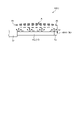
- FIG. 3 is a schematic diagram showing the irradiation range A of the first light Lc.
- the irradiation range A faces the outer peripheral surface 10 c of the leak portion 11 .
- the irradiation range A is drawn as if it exists only on one side of the outer peripheral surface 10c (upper side in FIG. 3), but it is actually a cylindrical area surrounding the outer peripheral surface 10c. can be done.
- the end portion 10b is located near the end portion At on the tip side of the irradiation range A, and is located so as to face the end portion At. Therefore, the end portion 10b can receive the second light Lr from the end portion At of the irradiation range A. As shown in FIG.
- an inclined surface 10b1 inclined with respect to the axial direction X is provided at the end portion 10b of the core 10d.
- the second light directed radially inward is axially reflected by the inclined surface 10b1.
- the direction of reflection can be appropriately adjusted by the inclination of the inclined surface 10b1.
- Inclined surface 10b1 is an example of an optical element.
- the transmitting/receiving probe system 1 of the present embodiment detects whether or not the irradiation range A is irradiated with the first light Lc and the irradiation intensity by, for example, receiving and detecting the second light Lr in the light receiving unit 250. can be determined or determined.
- the second light Lr may be reflected light of the first light Lc from the irradiation range A, or may be fluorescence caused by the first light Lc in the irradiation range A.
- the transmitting/receiving probe 10 has a coating layer surrounding the core 10d between the first clad 10e of the leakage portion 11 and the end portion 10b of the core 10d. has 13.
- the coating layer 13 surrounds the core 10d on the side opposite to the end portion 10a in the axial direction with respect to the leak portion 11, and suppresses direct coupling of the first light Lc to the core 10d.
- the coating layer 13 may have an absorption layer that absorbs light.
- the absorber layer can be configured as a blackened layer made of, for example, a copper oxide coating.
- the coating layer 13 can suppress the first light Lc from being coupled to the core 10d and emitted from the end portion 10b to irradiate an unintended range. Moreover, the coating layer 13 can prevent the first light input to the core 10d from interfering with the second light and weakening the output of the second light. Note that the coating layer 13 may be configured to surround the outer periphery of the first clad 10e.
- the coating layer 13 is an example of a second coating layer.
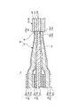
- FIG. 4 is a cross-sectional view of part of the coupling section 30 and the transmitting/receiving probe 10.
- the connecting portion 30 is connected to the transmitting/receiving probe 10 by being fused or adhered. That is, the coupling section 30 is optically and mechanically connected to the transmitting/receiving probe 10 .
- another member may be configured so that the end surface of the coupling portion 30 and the end surface of the transmitting/receiving probe are in contact with each other.
- the coupling section 30 has a fiber bundle in which a plurality of delivery optical fibers 20 are bundled.
- the fiber bundle is, for example, a tapered fiber bundle that narrows as it approaches the transmitting/receiving probe 10 .
- the ends of seven delivery optical fibers 20 of the same diameter are bundled in a close-packed manner.
- Each delivery optical fiber 20 has a core 20a, a clad 20b surrounding the core 20a, and an outer skin 20c surrounding the clad 20b.
- a portion from which the outer skin 20c is removed constitutes a coupling portion 30 having a tapered portion 31 and a straight portion 32.
- the outer diameter gradually becomes smaller as it approaches the transmitting/receiving probe 10, and the clad 20b of the adjacent delivery optical fiber 20 is integrated.
- the connecting portion 30 may not have the straight portion 32 .
- the number of bundled optical fibers is not limited to seven, and the fiber bundle may have at least two bundled delivery optical fiber 20 ends.
- the fiber bundle may also have optical fibers other than the delivery optical fibers 20 optically connected to each delivery optical fiber 20 .
- the end surface 10a2 of the first clad 10e of the transmitting/receiving probe 10 faces the end surface of the delivery optical fiber 22 radially outwardly displaced from the optical axis Ax.
- the end surface 10a2 is part of the end portion 10a.
- the delivery optical fiber 22 is optically connected to the light source unit 112 (110).
- the coupler 30 couples the light output from the light source unit 112 and transmitted by the delivery optical fiber 22 to the first clad 10e. That is, the light source of the light source unit 112 outputs light coupled to the first clad 10e, that is, the first light.
- Delivery optical fiber 22 is an example of a first transmission optical fiber.
- a portion of the coupling portion 30 that optically connects the delivery optical fiber 22 and the first clad 10e, that is, the end portion of the delivery optical fiber 22 is an example of the first coupling portion.
- a plurality of delivery optical fibers 22 are optically connected to the first clad 10e. Therefore, when the plurality of light source units 112 output light in parallel, the first light output from the plurality of light source units 112 is coupled to the first clad 10 e via the coupling section 30 .
- the end surface 10a1 of the core 10d of the transmitting/receiving probe 10 faces the end surface of the delivery optical fiber 21 positioned at the center of the bundle.
- the end surface 10a1 is part of the end portion 10a.
- the delivery optical fiber 21 is optically connected to the light receiver 250 .
- the coupling portion 30 optically connects the core 10 d and the delivery optical fiber 21 .
- the delivery optical fiber 21 is an example of a second transmission optical fiber.
- a portion of the coupling portion 30 that optically connects the core 10d and the delivery optical fiber 21, that is, the end portion of the delivery optical fiber 21 is an example of a second coupling portion.
- the coupling portion 30 is an example of an integrated coupling portion having a first coupling portion and a second coupling portion.
- the end face of the delivery optical fiber 20 does not face the end face 10a3 of the second clad 10f.
- the end surface 10a3 may be provided with a shielding portion so that external light or the like is not coupled to the second clad 10f.
- the numerical aperture of the light source unit 112 is set to be substantially the same as or slightly smaller than the numerical aperture of the delivery optical fiber 22 .
- the numerical aperture of the delivery optical fiber 22 is substantially the same as or slightly smaller than the numerical aperture of the first clad 10e. is set small to Similarly, the numerical aperture of the light receiving section 250 is set to be substantially the same as or slightly smaller than the numerical aperture of the delivery optical fiber 21 .
- the numerical aperture of the delivery optical fiber 21 is substantially the same as or slightly smaller than the numerical aperture of the core 10d. is set.
- the numerical aperture of the first clad 10e is larger than that of the core 10d. Therefore, the numerical aperture of the light source unit 112 is larger than that of the light receiving section 250 .
- the setting of the numerical apertures of the light source unit 112 and the light receiving section 250 can be changed, for example, by designing the numerical aperture of the lens system (not shown).
- the control device 200 can switch between outputting and stopping the output of light from each light source unit 110 . Therefore, by controlling the operation of each light source unit 110 by the control device 200, the first light output from the light source unit 112 is output from the outer peripheral surface 10c of the leakage portion 11 of the transmitting/receiving probe 10, and from the transmitting/receiving probe 10 A state in which the first light is not output can be switched. Furthermore, the control device 200 can change the intensity of the first light leaking from the outer peripheral surface 10c in the leaking portion 11 by changing the number of the light source units 112 that output the first light.
- control device 200 can switch between the above-described operation states and strengths based on instruction signals based on the operator's operation input on the input unit 220 .
- FIG. 5 is a block diagram of the transmit/receive probe system 1.
- the transmitter/receiver probe system 1 includes a control device 200 , an input section 220 , an output section 230 and a light receiver 250 .
- the input unit 220 and the output unit 230 construct a user interface for users and operators.
- the input unit 220 is, for example, an input device such as a remote controller, an operation unit such as a switch box or joystick, a keyboard, a touch panel, a mouse, a switch, or an operation button.
- the output unit 230 is, for example, a display, a printer, a lamp, a speaker, or the like, and is an output device for images, printing, and sound.
- the control device 200 also has a controller 210 , a main storage unit 241 and an auxiliary storage device 242 .
- the controller 210 is, for example, a processor (circuit) such as a CPU (central processing unit).
- the main storage unit 241 is, for example, RAM (random access memory) or ROM (read only memory).
- the auxiliary storage device 242 is, for example, a non-volatile rewritable storage device such as an SSD (solid state drive) or HDD (hard disk drive).
- the controller 210 reads programs stored in the main storage unit 241 and the auxiliary storage device 242 and executes each process, thereby operating as an irradiation control unit 211, an input control unit 212, an output control unit 213, and a detection unit 214. do.
- the program can be provided as an installable file or an executable file recorded on a computer-readable recording medium.
- a recording medium may also be referred to as a program product.
- Values used in arithmetic processing by programs and processors, information such as maps and tables may be stored in advance in the main storage unit 241 and auxiliary storage device 242, or may be stored in the storage unit of a computer connected to a communication network. and stored in the auxiliary storage device 242 by being downloaded via the communication network.
- Auxiliary storage device 242 stores data written by the processor. Also, the computational processing by controller 210 may be performed, at least in part, by hardware. In this case, the controller 210 may include, for example, an FPGA (field programmable gate array) or an ASIC (application specific integrated circuit).
- FPGA field programmable gate array
- ASIC application specific integrated circuit
- the irradiation control unit 211 can individually control light output and output stop for each of the light source units 110 included in the light output device 100 .
- the irradiation control unit 211 can switch the light source unit 110 that outputs light among the plurality of light source units 110 (light sources) according to the operator's operation input to the input unit 220 .
- the irradiation controller 211 is an example of a controller.
- the input control section 212 receives an input signal from the input section 220 . Further, the input control section 212 may control the input section 220 so that a predetermined operation input is possible.
- the output control unit 213 controls the output unit 230 to perform a predetermined output.
- the detection unit 214 can detect the received light intensity of the second light based on the second light received by the light receiving unit 250 .
- FIG. 6 and 7 are cross-sectional views each showing an example of the configuration of the leak portion 11.
- FIG. The inside of the first clad 10e of the leak portion 11 contains particles 11b in the example of FIG. 6, and contains holes 11c in the example of FIG.
- the particles 11b and the holes 11c may be nanostructures with a diameter of 100 [nm] or less, for example.
- Particles 11b may be, for example, microparticles or fillers such as microtubes.
- the traveling direction of the first light is changed by the particles 11b and the holes 11c, that is, the first light is scattered, so the first light tends to leak outward in the radial direction from the outer peripheral surface 10c.
- FIG. 8 is a cross-sectional view showing another example of the configuration of the leak portion 11.
- the outer peripheral surface 10c is inclined with respect to the axial direction X of the transmitting/receiving probe 10.
- the outer peripheral surface 10c is, for example, a tapered surface. In this way, in the portion where the shape of the outer peripheral surface 10c changes along the axial direction X, for example, the first light is incident on the portion exceeding the critical angle, so that the first light is emitted from the outer peripheral surface 10c in the radial direction. It leaks easily to the outside.
- FIG. 9 is a cross-sectional view showing another example of the configuration of the leak portion 11. As shown in FIG. In the example of FIG. 9, the leak portion 11 is bent. Light leaks easily from the bent portion. That is, even with the configuration of FIG. 9, the first light tends to leak outward in the radial direction from the outer peripheral surface 10c.
- FIG. 10 is a cross-sectional view showing another example of the configuration of the leak portion 11.
- the leakage portion 11 has a scattering layer 14 surrounding the first clad 10e.
- the refractive index of the scattering layer 14 is set substantially equal to or slightly higher than the refractive index of the first clad 10e.
- the scattering layer 14 also contains scattering elements 14a as particles and holes. In this case, the first light that reaches the interface between the first cladding 10e and the scattering layer 14 enters the scattering layer 14 and leaks radially outward from the scattering elements 14a.
- the scattering layer 14 can appropriately set or change the location where the first light leaks, the location where the first light leaks easily, or the location where the intensity of the leaked light increases. You get the advantage of being able to Further, when the first clad 10e is appropriately pressurized radially inward by the scattering layer 14, the first light is likely to leak from the pressurized portion.
- FIGS. 6 to 10 may be combined as appropriate in one transmitting/receiving probe 10 .
- FIG. 11 An optical element 15A having an inclined surface 15a similar to the inclined surface 10b1 shown in FIG.
- the refractive index of the optical element 15A is set substantially equal to or higher than the refractive index of the core 10d.
- an advantage is obtained that the optical element 15A for illuminating an appropriate area can be retrofitted to the core 10d of the transmitting/receiving probe 10.
- FIG. The inclined surface 15a is an example of an optical element.
- an optical element 15B having a conical surface 15b sharpened in the axial direction X is attached to an end portion 10b of a core 10d by fusion, adhesion, or the like.
- the refractive index of the optical element 15A is set substantially equal to or higher than the refractive index of the core 10d.
- the same effects as those of the configurations of FIGS. 2, 3 and 11 can be obtained.
- Conical surface 15b is an example of an optical element.
- the irradiation range of the second light can be narrowed, the irradiation range can be widened, the irradiation position can be appropriately adjusted, the irradiation intensity can be increased, or the irradiation intensity can be increased.
- An advantage is obtained in that the irradiation state of the second light can be appropriately adjusted, such as by lowering it.
- Lens 15c is an example of an optical element.
- an optical element 15D having a convex curved surface 15d such as a spherical surface is attached to the end portion 10b of the core 10d by fusion, adhesion, or the like.
- a convex curved surface 15d such as a spherical surface
- the convex curved surface 15d is an example of an optical element.
- FIG. 15 shows part of a modified optical output device 100A.
- a coupler 23 is provided in the middle of the delivery optical fiber 21, and the light source unit 111 (110) is connected to the core 10d via the delivery optical fiber 22, the coupler 23, and the delivery optical fiber 21. properly connected.
- the light (third light) output from the light source unit 111 and transmitted through the core 10d can be output from the end portion 10b.
- the inclined surfaces 10b1 and 15a provided at the end portion 10b, the conical surface 15b, the lens 15c, the convex curved surface 15d, the optical elements 15A to 15D, etc. direct the third light traveling in the axial direction outward in the radial direction. .
- the irradiation control section 211 can individually control light output and output stop for each of the light source units 110 (111, 112) included in the light output device 100. Further, the irradiation control unit 211 can switch the light source unit 110 that outputs light among the plurality of light source units 110 (111, 112) according to the operator's operation input to the input unit 220.
- FIG. 1 A block diagram illustrating an exemplary computing environment in accordance with the present in the light output device 100.
- FIG. 16 is a sectional view of the leakage portion 11 of the transmitting/receiving probe 10A of the modified example.
- the transmitting/receiving probe 10A is configured as a multi-core optical fiber having a plurality of cores 10d arranged in parallel and a first clad 10e surrounding the plurality of cores 10d. .
- the number of cores 10d can be increased, and the cores 10d can be arranged closer to the irradiation range A, so that the intensity of the second light received by the light receiving unit 250 can be increased.
- the detection sensitivity of the second light in the detection unit 214 can be further enhanced.
- the number of cores 10d is not limited to seven as long as it is two or more.
- the transmitting/receiving probe system 1 of the present embodiment can irradiate a wider irradiation range A facing the outer peripheral surface 10c of the transmitting/receiving probe 10 with light. That is, according to this embodiment, the irradiation range A can be further expanded.
- the transmitting/receiving probe system 1 of the present embodiment can detect the irradiation intensity of the end portion At of the irradiation range A facing the end portion 10 b of the transmitting/receiving probe 10 .
- the transmitting/receiving probe system 1 compares the light intensity of the second light Lr from the end At of the irradiation range A with a threshold, for example, to determine whether or not the desired width of the irradiation range A is obtained. and whether or not the desired irradiation intensity is obtained for the irradiation range A can be determined.
- the configuration of the present embodiment is particularly effective when an irradiation intensity equal to or higher than a predetermined intensity is required. It is.
- the transmitter/receiver probe 10 of the present embodiment and the transmitter/receiver probe system 1 including the transmitter/receiver probe 10 can be used for photodynamic therapy (PDT).
- PDT photodynamic therapy
- the transmitting/receiving probe system 1 of this embodiment can also be used for photodynamic diagnosis (PDD).
- PDT photodynamic diagnosis
- the glioma that has taken up the fluorescent labeling agent is irradiated with blue light with a wavelength of 400 to 410 [nm] as the first light Lc, and red light with a wavelength of about 600 [nm] as the second light Lr.
- the first light Lc is emitted and the second light Lr is received while the transmitter/receiver probe 10 is pushed in or pulled out. It is possible to detect the existence range of the glioma. This provides the advantage that, for example, the PDT for the existence range can be performed more reliably or more efficiently.
- detection of the existence range that is, PDD
- irradiation therapy that is, PDT
- the present invention can be used for a transmitting/receiving probe system and a transmitting/receiving probe.
- Lens optical element 15d... Convex curved surface (optical element) Reference Signs List 20 Delivery optical fiber 20a Core 20b Clad 20c Coating 21 Delivery optical fiber (second transmission optical fiber, second coupling portion) 22... Delivery optical fiber (first transmission optical fiber, first coupling section) 23... Coupler 30... Coupling portion (first coupling portion, second coupling portion, integrated coupling portion) 31... Tapered portion 32... Straight portion 100, 100A... Light output device 110... Light source unit 111... Light source unit 112... Light source unit 200... Control device 210... Controller 211... Irradiation control section 212... Input control section 213...
- Output control section 214 Detecting section 220 Input section 230 Output section 241 Main storage section 242 Auxiliary storage device 250 Light receiving section A Irradiation range At End Ax Optical axis Lc First light Lr Second light X Axis direction
Landscapes
- Physics & Mathematics (AREA)
- Optics & Photonics (AREA)
- Health & Medical Sciences (AREA)
- General Physics & Mathematics (AREA)
- Life Sciences & Earth Sciences (AREA)
- Engineering & Computer Science (AREA)
- Biomedical Technology (AREA)
- General Health & Medical Sciences (AREA)
- Veterinary Medicine (AREA)
- Animal Behavior & Ethology (AREA)
- Pathology (AREA)
- Public Health (AREA)
- Biophysics (AREA)
- Nuclear Medicine, Radiotherapy & Molecular Imaging (AREA)
- Radiology & Medical Imaging (AREA)
- Heart & Thoracic Surgery (AREA)
- Medical Informatics (AREA)
- Molecular Biology (AREA)
- Surgery (AREA)
- Optical Couplings Of Light Guides (AREA)
- Measurement Of The Respiration, Hearing Ability, Form, And Blood Characteristics Of Living Organisms (AREA)
- Investigating Or Analysing Materials By Optical Means (AREA)
Abstract
Description
[送受光プローブシステムの構成]
図1は、実施形態の送受光プローブシステム1の模式図である。図1に示されるように、送受光プローブシステム1は、光出力装置100と、送受光プローブ10と、制御装置200と、デリバリ光ファイバ20と、結合部30と、入力部220と、受光部250と、を備えている。
図2は、送受光プローブ10の断面と結合部30の側面とを示す図である。上述したように、送受光プローブ10は、伝送部12と、漏洩部11と、を有している。本実施形態では、一例として、伝送部12は、ダブルクラッドファイバとして構成されている。すなわち、伝送部12は、軸方向に延びたコア10dと、コア10dを取り囲み軸方向に延びた第一クラッド10eと、第一クラッドを取り囲み軸方向に延びた第二クラッド10fと、を有している。第一クラッド10eの屈折率は、コア10dの屈折率よりも低く、かつ第二クラッド10fの屈折率は、第一クラッド10eの屈折率よりも低い。
図4は、結合部30および送受光プローブ10の一部の断面図である。結合部30は、融着あるいは接着等されることにより送受光プローブ10と接続されている。すなわち、結合部30は、送受光プローブ10と光学的および機械的に接続されている。なお、他の部材(不図示)により、結合部30の端面と送受光プローブの端面とが接するように構成されてもよい。
図5は、送受光プローブシステム1の、ブロック図である。図5に示されるように、送受光プローブシステム1は、制御装置200、入力部220、出力部230、および受光部250を備えている。入力部220および出力部230は、ユーザやオペレータに対するユーザインタフェースを構築している。入力部220は、例えば、リモートコントローラや、スイッチボックス、ジョイスティックのような操作ユニット、キーボード、タッチパネル、マウス、スイッチ、操作ボタンのような、入力デバイスである。出力部230は、例えば、ディスプレイや、プリンタ、ランプ、スピーカ等であって、画像や、印刷、音声による出力デバイスである。
図6および図7は、それぞれ、漏洩部11の構成の一例を示す断面図である。漏洩部11の第一クラッド10eの内部には、図6の例では、粒子11bが含まれており、図7の例では、空孔11cが含まれている。粒子11bや空孔11cは、例えば、直径100[nm]以下のような、ナノ構造であってもよい。粒子11bは、例えば、微粒子や、微少チューブのようなフィラーであってもよい。これらの場合、粒子11bや空孔11cによって第一光の進行方向が変化する、すなわち第一光が散乱されるため、第一光が外周面10cから径方向外側へ漏れやすくなる。
図11は、コア10dの端部10bに、図3に示された傾斜面10b1と同様の傾斜面15aを有した光学要素15Aが、融着や接着等により取り付けられている。この場合、光学要素15Aの屈折率は、コア10dの屈折率と略同じかあるいはより高く設定される。このような構成によっても、図2,3の構成と同様の効果が得られる。また、図11の構成によれば、送受光プローブ10のコア10dに、適宜な領域を照らす光学要素15Aを後付けできるという利点が得られる。傾斜面15aは、光学要素の一例である。
図15は、変形例の光出力装置100Aの一部を示している。図15の例では、デリバリ光ファイバ21の途中にカプラ23が設けられており、光源ユニット111(110)が、デリバリ光ファイバ22、カプラ23、およびデリバリ光ファイバ21を介して、コア10dと光学的に接続されている。この場合、光源ユニット111から出力されコア10dを伝送された光(第三光)を、端部10bから出力することができる。
図16は、変形例の送受光プローブ10Aの漏洩部11の断面図である。図16に示されるように、送受光プローブ10Aは、複数の並列に配置されたコア10dと、複数のコア10dを取り囲んだ第一クラッド10eと、を有した、マルチコア光ファイバとして構成されている。この場合、例えば、コア10dの数を増やすことができるとともに、コア10dをより照射範囲Aに近づけて配置することができるため、受光部250における第二光の受光強度を増大することができ、ひいては検出部214における第二光の検出感度をより高めることができる。なお、コア10dの数は、2以上であればよく、7には限定されない。
10,10A…送受光プローブ
10a…端部(第一端部)
10a1…端面
10a2…端面
10a3…端面
10b…端部(第二端部)
10b1…傾斜面(光学要素)
10c…外周面
10d…コア
10e…第一クラッド
10f…第二クラッド(第一被覆層)
11…漏洩部
11a…凹部
11b…粒子
11c…空孔
12…伝送部
13…被覆層(第二被覆層)
14…散乱層
14a…散乱要素
15A~15D…光学要素
15a…傾斜面(光学要素)
15b…円錐面(光学要素)
15c…レンズ(光学要素)
15d…凸曲面(光学要素)
20…デリバリ光ファイバ
20a…コア
20b…クラッド
20c…外皮
21…デリバリ光ファイバ(第二伝送光ファイバ、第二結合部)
22…デリバリ光ファイバ(第一伝送光ファイバ、第一結合部)
23…カプラ
30…結合部(第一結合部、第二結合部、統合結合部)
31…テーパ部
32…直線部
100,100A…光出力装置
110…光源ユニット
111…光源ユニット
112…光源ユニット
200…制御装置
210…コントローラ
211…照射制御部
212…入力制御部
213…出力制御部
214…検出部
220…入力部
230…出力部
241…主記憶部
242…補助記憶装置
250…受光部
A…照射範囲
At…端部
Ax…光軸
Lc…第一光
Lr…第二光
X…軸方向
Claims (30)
- 少なくとも一つの光源と、
軸方向の第一端部と、軸方向において当該第一端部とは反対側の第二端部と、コアと、当該コアを取り囲む第一クラッドと、前記光源から出力され前記第一端部において前記第一クラッドと結合され当該第一クラッドを伝送された第一光を当該第一クラッドの外周面から径方向外側に漏洩する漏洩部と、を有した、送受光プローブと、
外部から到来し前記第二端部において前記コアに結合され当該コアを伝送され前記第一端部において当該コアから出力された第二光を受光する受光部と、
前記受光部が受光した前記第二光を検出する検出部と、
を備えた、送受光プローブシステム。 - 前記第一端部の軸心から径方向外側にずれた位置に面し前記少なくとも一つの光源から出力された光を前記第一クラッドに結合する第一結合部と、
前記第一端部の前記第一結合部よりも前記軸心の近くに面し、前記第一端部において前記コアから出力された光が結合される第二結合部と、
を有した統合結合部を備えた、請求項1に記載の送受光プローブシステム。 - 前記送受光プローブは、前記第一端部と前記漏洩部との間において、前記第一クラッドの外周面を取り囲む第一被覆層を有した、請求項1または2に記載の送受光プローブシステム。
- 前記第一被覆層は、前記第一クラッドよりも屈折率が低い第二クラッドを含む、請求項3に記載の送受光プローブシステム。
- 前記送受光プローブは、径方向の最も外側を取り囲む外皮を有した、請求項1~4のうちいずれか一つに記載の送受光プローブシステム。
- 前記外皮は、樹脂材料で作られた、請求項5に記載の送受光プローブシステム。
- 前記送受光プローブは、前記漏洩部から軸方向に外れた位置で、前記第一クラッドの外周面が露出した区間を有した、請求項1または2に記載の送受光プローブシステム。
- 前記送受光プローブは、前記漏洩部に対して前記第一端部とは軸方向の反対側において前記第一クラッドを取り囲み、前記第一光が前記漏洩部から前記コアに直接結合するのを抑制する第二被覆層を有した、請求項1~7のうちいずれか一つに記載の送受光プローブシステム。
- 前記第二端部において径方向内側に進む光の向きを変えて前記コアに向かわせる光学要素を有した、請求項1~8のうちいずれか一つに記載の送受光プローブシステム。
- 前記漏洩部は、前記第一クラッドの外周面に設けられた凹部または凸部を含む、請求項1~9のうちいずれか一つに記載の送受光プローブシステム。
- 前記漏洩部は、前記第一クラッドの内部に設けられた粒子または空孔を含む、請求項1~10のうちいずれか一つに記載の送受光プローブシステム。
- 前記漏洩部は、軸方向に向かうにつれて前記第一クラッドの外周面の形状が変化する区間を含む、請求項1~11のうちいずれか一つに記載の送受光プローブシステム。
- 前記漏洩部は、前記第一クラッドの屈曲部を含む、請求項1~12のうちいずれか一つに記載の送受光プローブシステム。
- 前記漏洩部は、前記第一クラッドの径方向外側に設けられ前記第一クラッドからの光を導入して径方向外側へ散乱する散乱層を有した、請求項1~13のうちいずれか一つに記載の送受光プローブシステム。
- 前記統合結合部は、前記第一端部と光学的に接続された、請求項2に記載の送受光プローブシステム。
- 前記統合結合部は、前記第一光を伝送し前記第一結合部としての端部を有した第一伝送光ファイバと、前記第二光を伝送し前記第二結合部としての端部を有した第二伝送光ファイバと、が束ねられたファイババンドルを有した、請求項2または15に記載の送受光プローブシステム。
- 前記ファイババンドルは、前記送受光プローブに近づくにつれて細くなるテーパードファイババンドルである、請求項16に記載の送受光プローブシステム。
- 前記少なくとも一つの光源と前記第一端部における前記コアとが光学的に接続され、当該光源から出力され前記コアを伝送された第三光が前記第二端部から出力可能に構成された請求項1~17のうちいずれか一つに記載の送受光プローブシステム。
- 前記少なくとも一つの光源としての複数の光源と、
前記複数の光源のうち光を出力する光源を切り換える制御部と、を備えた、請求項1~18のうちいずれか一つに記載の送受光プローブシステム。 - 前記複数の光源は、前記第一光を出力する複数の光源を含む、請求項19に記載の送受光プローブシステム。
- 前記少なくとも一つの光源と前記第一端部における前記コアとが光学的に接続され、当該光源から出力され前記コアを伝送された第三光が前記第二端部から出力可能に構成され、
前記複数の光源は、前記第一光および前記第三光を出力する光源を含む、請求項19または20に記載の送受光プローブシステム。 - ユーザによる操作入力部を備え、
前記制御部は、前記操作入力部に対するユーザの操作入力に応じて前記複数の光源のうち光を出力する光源を切り替える、請求項19~21のうちいずれか一つに記載の送受光プローブシステム。 - 前記送受光プローブは、前記コアとして、並列に配置された複数のコアを有した、請求項1~22のうちいずれか一つに記載の送受光プローブシステム。
- 軸方向の第一端部と、
軸方向において当該第一端部とは反対側の第二端部と、
軸方向に延びたコアと、
当該コアを取り囲み軸方向に延びた第一クラッドと、
前記第一クラッドの前記第一端部よりも前記第二端部の近くに設けられ、光源から出力され前記第一端部において前記第一クラッドと結合され当該第一クラッドを伝送された第一光を、当該第一クラッドの外周面から径方向外側に漏洩する漏洩部と、
を有した、送受光プローブ。 - 前記第一端部の軸心から径方向外側にずれた位置に面し少なくとも一つの光源から出力された光を前記第一クラッドに結合する第一結合部と、
前記第一端部の前記第一結合部よりも前記軸心の近くに面し、前記第一端部において前記コアから出力された光が結合される第二結合部と、
を有した統合結合部を有した、請求項24に記載の送受光プローブ。 - 前記第一端部と前記漏洩部との間において、前記第一クラッドの外周面を取り囲む第一被覆層を有した、請求項24または25に記載の送受光プローブ。
- 前記第一被覆層は、前記第一クラッドよりも屈折率が低い第二クラッドを含む、請求項26に記載の送受光プローブ。
- 径方向の最も外側を取り囲む外皮を有した、請求項24~27のうちいずれか一つに記載の送受光プローブ。
- 前記漏洩部に対して前記第一端部とは軸方向の反対側において前記第一クラッドを取り囲み、前記第一光が前記漏洩部から前記コアに直接結合するのを抑制する第二被覆層を有した、請求項24~28のうちいずれか一つに記載の送受光プローブ。
- 前記第二端部において径方向内側に進む光の向きを変えて前記コアに向かわせる光学要素を有した、請求項24~29のうちいずれか一つに記載の送受光プローブ。
Priority Applications (4)
| Application Number | Priority Date | Filing Date | Title |
|---|---|---|---|
| CN202280024105.3A CN117062652A (zh) | 2021-03-30 | 2022-03-17 | 光发送接收探针系统及光发送接收探针 |
| JP2023510964A JP7789059B2 (ja) | 2021-03-30 | 2022-03-17 | 送受光プローブシステムおよび送受光プローブ |
| EP22780215.4A EP4316579A4 (en) | 2021-03-30 | 2022-03-17 | LIGHT TRANSMITTING/RECEIVING PROBE SYSTEM AND LIGHT TRANSMITTING/RECEIVING PROBE |
| US18/464,606 US20230417973A1 (en) | 2021-03-30 | 2023-09-11 | Light transmission/reception probe system and light transmission/reception probe |
Applications Claiming Priority (2)
| Application Number | Priority Date | Filing Date | Title |
|---|---|---|---|
| JP2021056435 | 2021-03-30 | ||
| JP2021-056435 | 2021-03-30 |
Related Child Applications (1)
| Application Number | Title | Priority Date | Filing Date |
|---|---|---|---|
| US18/464,606 Continuation US20230417973A1 (en) | 2021-03-30 | 2023-09-11 | Light transmission/reception probe system and light transmission/reception probe |
Publications (1)
| Publication Number | Publication Date |
|---|---|
| WO2022209996A1 true WO2022209996A1 (ja) | 2022-10-06 |
Family
ID=83459164
Family Applications (1)
| Application Number | Title | Priority Date | Filing Date |
|---|---|---|---|
| PCT/JP2022/012467 Ceased WO2022209996A1 (ja) | 2021-03-30 | 2022-03-17 | 送受光プローブシステムおよび送受光プローブ |
Country Status (5)
| Country | Link |
|---|---|
| US (1) | US20230417973A1 (ja) |
| EP (1) | EP4316579A4 (ja) |
| JP (1) | JP7789059B2 (ja) |
| CN (1) | CN117062652A (ja) |
| WO (1) | WO2022209996A1 (ja) |
Citations (6)
| Publication number | Priority date | Publication date | Assignee | Title |
|---|---|---|---|---|
| JP2001502438A (ja) * | 1996-09-16 | 2001-02-20 | フォーカル・インコーポレーテッド | 光ファイバの光散乱体及びその製造方法 |
| JP2010501202A (ja) * | 2006-02-01 | 2010-01-21 | ザ ジェネラル ホスピタル コーポレイション | コンフォーマルレーザ治療手順を用いてサンプルの少なくとも一部分の情報をモニタ及び取得し、電磁放射を放射する方法及びシステム |
| JP2011104199A (ja) | 2009-11-19 | 2011-06-02 | Fujifilm Corp | 内視鏡装置 |
| JP2013142792A (ja) * | 2012-01-11 | 2013-07-22 | Hitachi Cable Ltd | 光ファイバの加工方法、光ファイバの加工装置、光ファイバ及び光ファイバ入出力構造 |
| JP2015510142A (ja) * | 2012-01-31 | 2015-04-02 | アシメトリック メディカル リミテッド | 曲げによって放射線を発するように構成される光ファイバ |
| CN111552026A (zh) * | 2020-04-10 | 2020-08-18 | 桂林电子科技大学 | 一种用于人体介入可视化光动力治疗的光纤及系统 |
Family Cites Families (4)
| Publication number | Priority date | Publication date | Assignee | Title |
|---|---|---|---|---|
| WO2018153714A1 (en) | 2017-02-21 | 2018-08-30 | Philips Lighting Holding B.V. | 3d printed luminaires using optical fibers |
| EP3683608B1 (en) | 2019-01-18 | 2025-03-26 | TE Connectivity Germany GmbH | Optical cable |
| US12390656B2 (en) * | 2019-06-12 | 2025-08-19 | Kaneka Corporation | Light therapy diagnostic device and method for operating the same |
| JP7257540B2 (ja) * | 2019-09-30 | 2023-04-13 | 株式会社フジクラ | 光コンバイナ及びレーザ装置 |
-
2022
- 2022-03-17 CN CN202280024105.3A patent/CN117062652A/zh active Pending
- 2022-03-17 JP JP2023510964A patent/JP7789059B2/ja active Active
- 2022-03-17 EP EP22780215.4A patent/EP4316579A4/en active Pending
- 2022-03-17 WO PCT/JP2022/012467 patent/WO2022209996A1/ja not_active Ceased
-
2023
- 2023-09-11 US US18/464,606 patent/US20230417973A1/en active Pending
Patent Citations (6)
| Publication number | Priority date | Publication date | Assignee | Title |
|---|---|---|---|---|
| JP2001502438A (ja) * | 1996-09-16 | 2001-02-20 | フォーカル・インコーポレーテッド | 光ファイバの光散乱体及びその製造方法 |
| JP2010501202A (ja) * | 2006-02-01 | 2010-01-21 | ザ ジェネラル ホスピタル コーポレイション | コンフォーマルレーザ治療手順を用いてサンプルの少なくとも一部分の情報をモニタ及び取得し、電磁放射を放射する方法及びシステム |
| JP2011104199A (ja) | 2009-11-19 | 2011-06-02 | Fujifilm Corp | 内視鏡装置 |
| JP2013142792A (ja) * | 2012-01-11 | 2013-07-22 | Hitachi Cable Ltd | 光ファイバの加工方法、光ファイバの加工装置、光ファイバ及び光ファイバ入出力構造 |
| JP2015510142A (ja) * | 2012-01-31 | 2015-04-02 | アシメトリック メディカル リミテッド | 曲げによって放射線を発するように構成される光ファイバ |
| CN111552026A (zh) * | 2020-04-10 | 2020-08-18 | 桂林电子科技大学 | 一种用于人体介入可视化光动力治疗的光纤及系统 |
Non-Patent Citations (1)
| Title |
|---|
| See also references of EP4316579A4 |
Also Published As
| Publication number | Publication date |
|---|---|
| JP7789059B2 (ja) | 2025-12-19 |
| US20230417973A1 (en) | 2023-12-28 |
| JPWO2022209996A1 (ja) | 2022-10-06 |
| EP4316579A4 (en) | 2024-12-18 |
| CN117062652A (zh) | 2023-11-14 |
| EP4316579A1 (en) | 2024-02-07 |
Similar Documents
| Publication | Publication Date | Title |
|---|---|---|
| US8641607B2 (en) | Light-guide, light source apparatus and endoscope system | |
| US11553964B2 (en) | Optical probe, medical laser probe, and cauterization device | |
| US4543477A (en) | Safety device for detecting trouble in optical transmission fibers | |
| CN105709338B (zh) | 用于活体的眼睛的照射的系统 | |
| US8724945B2 (en) | High power fiber laser system with integrated termination block | |
| CN101788696B (zh) | 光纤 | |
| US20100191060A1 (en) | Light guide, light source apparatus and endoscope system | |
| US9645322B2 (en) | Optical probe for optical coherence tomography and manufacturing method therefor | |
| US10543042B2 (en) | Fiber optic laser surgical instrument having a radial dispersion pattern | |
| US6643428B2 (en) | Optical fiber collimator and method for fabricating the same | |
| JP7789059B2 (ja) | 送受光プローブシステムおよび送受光プローブ | |
| JP5983676B2 (ja) | 光プローブ | |
| US4942623A (en) | Device and method for modal separation and combination in an optical fiber intrusion detection system | |
| US5003623A (en) | Bimodal intrusion detection in an optical fiber communication system using graded index fiber | |
| WO2022209995A1 (ja) | 照射プローブシステムおよび照射プローブ | |
| US20240167949A1 (en) | Irradiation probe and irradiation probe system | |
| US20240192421A1 (en) | Radiation probe | |
| JP7620405B2 (ja) | 物体検出装置 | |
| CN223551928U (zh) | 滑环系统及医疗设备 | |
| CN221039507U (zh) | 一种侧射光纤组件 | |
| JP2001159580A (ja) | 光ファイバの漏洩光検出装置および方法 | |
| WO2023182227A1 (ja) | マルチコア光ファイバ | |
| WO2024018737A1 (ja) | 光ファイバの端面観察装置及び光ファイバの端面観察方法 | |
| JPWO2023026988A5 (ja) | ||
| JP2018007931A (ja) | 光プローブ |
Legal Events
| Date | Code | Title | Description |
|---|---|---|---|
| 121 | Ep: the epo has been informed by wipo that ep was designated in this application |
Ref document number: 22780215 Country of ref document: EP Kind code of ref document: A1 |
|
| WWE | Wipo information: entry into national phase |
Ref document number: 202280024105.3 Country of ref document: CN |
|
| WWE | Wipo information: entry into national phase |
Ref document number: 2023510964 Country of ref document: JP |
|
| WWE | Wipo information: entry into national phase |
Ref document number: 2022780215 Country of ref document: EP |
|
| NENP | Non-entry into the national phase |
Ref country code: DE |
|
| ENP | Entry into the national phase |
Ref document number: 2022780215 Country of ref document: EP Effective date: 20231030 |