WO2022210073A1 - 複層ガラスパネル - Google Patents
複層ガラスパネル Download PDFInfo
- Publication number
- WO2022210073A1 WO2022210073A1 PCT/JP2022/013036 JP2022013036W WO2022210073A1 WO 2022210073 A1 WO2022210073 A1 WO 2022210073A1 JP 2022013036 W JP2022013036 W JP 2022013036W WO 2022210073 A1 WO2022210073 A1 WO 2022210073A1
- Authority
- WO
- WIPO (PCT)
- Prior art keywords
- reflective
- glass panel
- pillars
- area
- glass plate
- Prior art date
- Legal status (The legal status is an assumption and is not a legal conclusion. Google has not performed a legal analysis and makes no representation as to the accuracy of the status listed.)
- Ceased
Links
Images









Classifications
-
- E—FIXED CONSTRUCTIONS
- E06—DOORS, WINDOWS, SHUTTERS, OR ROLLER BLINDS IN GENERAL; LADDERS
- E06B—FIXED OR MOVABLE CLOSURES FOR OPENINGS IN BUILDINGS, VEHICLES, FENCES OR LIKE ENCLOSURES IN GENERAL, e.g. DOORS, WINDOWS, BLINDS, GATES
- E06B9/00—Screening or protective devices for wall or similar openings, with or without operating or securing mechanisms; Closures of similar construction
- E06B9/24—Screens or other constructions affording protection against light, especially against sunshine; Similar screens for privacy or appearance; Slat blinds
-
- C—CHEMISTRY; METALLURGY
- C03—GLASS; MINERAL OR SLAG WOOL
- C03C—CHEMICAL COMPOSITION OF GLASSES, GLAZES OR VITREOUS ENAMELS; SURFACE TREATMENT OF GLASS; SURFACE TREATMENT OF FIBRES OR FILAMENTS MADE FROM GLASS, MINERALS OR SLAGS; JOINING GLASS TO GLASS OR OTHER MATERIALS
- C03C17/00—Surface treatment of glass, not in the form of fibres or filaments, by coating
- C03C17/34—Surface treatment of glass, not in the form of fibres or filaments, by coating with at least two coatings having different compositions
- C03C17/3411—Surface treatment of glass, not in the form of fibres or filaments, by coating with at least two coatings having different compositions with at least two coatings of inorganic materials
- C03C17/3417—Surface treatment of glass, not in the form of fibres or filaments, by coating with at least two coatings having different compositions with at least two coatings of inorganic materials all coatings being oxide coatings
-
- A—HUMAN NECESSITIES
- A01—AGRICULTURE; FORESTRY; ANIMAL HUSBANDRY; HUNTING; TRAPPING; FISHING
- A01M—CATCHING, TRAPPING OR SCARING OF ANIMALS; APPARATUS FOR THE DESTRUCTION OF NOXIOUS ANIMALS OR NOXIOUS PLANTS
- A01M29/00—Scaring or repelling devices, e.g. bird-scaring apparatus
- A01M29/06—Scaring or repelling devices, e.g. bird-scaring apparatus using visual means, e.g. scarecrows, moving elements, specific shapes, patterns or the like
- A01M29/08—Scaring or repelling devices, e.g. bird-scaring apparatus using visual means, e.g. scarecrows, moving elements, specific shapes, patterns or the like using reflection, colours or films with specific transparency or reflectivity
-
- C—CHEMISTRY; METALLURGY
- C03—GLASS; MINERAL OR SLAG WOOL
- C03C—CHEMICAL COMPOSITION OF GLASSES, GLAZES OR VITREOUS ENAMELS; SURFACE TREATMENT OF GLASS; SURFACE TREATMENT OF FIBRES OR FILAMENTS MADE FROM GLASS, MINERALS OR SLAGS; JOINING GLASS TO GLASS OR OTHER MATERIALS
- C03C27/00—Joining pieces of glass to pieces of other inorganic material; Joining glass to glass other than by fusing
- C03C27/06—Joining glass to glass by processes other than fusing
-
- E—FIXED CONSTRUCTIONS
- E06—DOORS, WINDOWS, SHUTTERS, OR ROLLER BLINDS IN GENERAL; LADDERS
- E06B—FIXED OR MOVABLE CLOSURES FOR OPENINGS IN BUILDINGS, VEHICLES, FENCES OR LIKE ENCLOSURES IN GENERAL, e.g. DOORS, WINDOWS, BLINDS, GATES
- E06B3/00—Window sashes, door leaves, or like elements for closing wall or like openings; Layout of fixed or moving closures, e.g. windows in wall or like openings; Features of rigidly-mounted outer frames relating to the mounting of wing frames
- E06B3/66—Units comprising two or more parallel glass or like panes permanently secured together
- E06B3/6612—Evacuated glazing units
-
- E—FIXED CONSTRUCTIONS
- E06—DOORS, WINDOWS, SHUTTERS, OR ROLLER BLINDS IN GENERAL; LADDERS
- E06B—FIXED OR MOVABLE CLOSURES FOR OPENINGS IN BUILDINGS, VEHICLES, FENCES OR LIKE ENCLOSURES IN GENERAL, e.g. DOORS, WINDOWS, BLINDS, GATES
- E06B3/00—Window sashes, door leaves, or like elements for closing wall or like openings; Layout of fixed or moving closures, e.g. windows in wall or like openings; Features of rigidly-mounted outer frames relating to the mounting of wing frames
- E06B3/66—Units comprising two or more parallel glass or like panes permanently secured together
- E06B3/663—Elements for spacing panes
- E06B3/66304—Discrete spacing elements, e.g. for evacuated glazing units
-
- E—FIXED CONSTRUCTIONS
- E06—DOORS, WINDOWS, SHUTTERS, OR ROLLER BLINDS IN GENERAL; LADDERS
- E06B—FIXED OR MOVABLE CLOSURES FOR OPENINGS IN BUILDINGS, VEHICLES, FENCES OR LIKE ENCLOSURES IN GENERAL, e.g. DOORS, WINDOWS, BLINDS, GATES
- E06B3/00—Window sashes, door leaves, or like elements for closing wall or like openings; Layout of fixed or moving closures, e.g. windows in wall or like openings; Features of rigidly-mounted outer frames relating to the mounting of wing frames
- E06B3/66—Units comprising two or more parallel glass or like panes permanently secured together
- E06B3/67—Units comprising two or more parallel glass or like panes permanently secured together characterised by additional arrangements or devices for heat or sound insulation or for controlled passage of light
-
- G—PHYSICS
- G02—OPTICS
- G02B—OPTICAL ELEMENTS, SYSTEMS OR APPARATUS
- G02B5/00—Optical elements other than lenses
- G02B5/20—Filters
- G02B5/208—Filters for use with infrared or ultraviolet radiation, e.g. for separating visible light from infrared and/or ultraviolet radiation
-
- G—PHYSICS
- G02—OPTICS
- G02B—OPTICAL ELEMENTS, SYSTEMS OR APPARATUS
- G02B5/00—Optical elements other than lenses
- G02B5/20—Filters
- G02B5/26—Reflecting filters
-
- E—FIXED CONSTRUCTIONS
- E06—DOORS, WINDOWS, SHUTTERS, OR ROLLER BLINDS IN GENERAL; LADDERS
- E06B—FIXED OR MOVABLE CLOSURES FOR OPENINGS IN BUILDINGS, VEHICLES, FENCES OR LIKE ENCLOSURES IN GENERAL, e.g. DOORS, WINDOWS, BLINDS, GATES
- E06B9/00—Screening or protective devices for wall or similar openings, with or without operating or securing mechanisms; Closures of similar construction
- E06B9/24—Screens or other constructions affording protection against light, especially against sunshine; Similar screens for privacy or appearance; Slat blinds
- E06B2009/2405—Areas of differing opacity for light transmission control
-
- E—FIXED CONSTRUCTIONS
- E06—DOORS, WINDOWS, SHUTTERS, OR ROLLER BLINDS IN GENERAL; LADDERS
- E06B—FIXED OR MOVABLE CLOSURES FOR OPENINGS IN BUILDINGS, VEHICLES, FENCES OR LIKE ENCLOSURES IN GENERAL, e.g. DOORS, WINDOWS, BLINDS, GATES
- E06B3/00—Window sashes, door leaves, or like elements for closing wall or like openings; Layout of fixed or moving closures, e.g. windows in wall or like openings; Features of rigidly-mounted outer frames relating to the mounting of wing frames
- E06B3/66—Units comprising two or more parallel glass or like panes permanently secured together
- E06B3/663—Elements for spacing panes
- E06B3/66309—Section members positioned at the edges of the glazing unit
-
- E—FIXED CONSTRUCTIONS
- E06—DOORS, WINDOWS, SHUTTERS, OR ROLLER BLINDS IN GENERAL; LADDERS
- E06B—FIXED OR MOVABLE CLOSURES FOR OPENINGS IN BUILDINGS, VEHICLES, FENCES OR LIKE ENCLOSURES IN GENERAL, e.g. DOORS, WINDOWS, BLINDS, GATES
- E06B3/00—Window sashes, door leaves, or like elements for closing wall or like openings; Layout of fixed or moving closures, e.g. windows in wall or like openings; Features of rigidly-mounted outer frames relating to the mounting of wing frames
- E06B3/66—Units comprising two or more parallel glass or like panes permanently secured together
- E06B3/67—Units comprising two or more parallel glass or like panes permanently secured together characterised by additional arrangements or devices for heat or sound insulation or for controlled passage of light
- E06B3/6715—Units comprising two or more parallel glass or like panes permanently secured together characterised by additional arrangements or devices for heat or sound insulation or for controlled passage of light specially adapted for increased thermal insulation or for controlled passage of light
Definitions
- the present invention relates to a multi-layer glass panel having a pair of glass plates.
- the multi-layer glass panel described in Patent Document 1 includes an antireflection coating laminated on the entire plate surface of the glass plate, and an ultraviolet reflectance coating laminated on the plate surface of the glass plate in a separate pattern arrangement.
- the color vision of birds is known to be "tetrachromatism" and includes the near-ultraviolet region. That is, birds can see colors in the ultraviolet range of 300 to 400 nm, which humans cannot see.
- the technique described in Patent Literature 1 provides a multi-layer glass panel capable of preventing birds from colliding by enhancing bird recognition by providing an ultraviolet reflectance coating on a glass plate based on the color vision of birds.
- the multi-layer glass panel described in Patent Document 1 has an antireflection coating and an ultraviolet reflectance coating, and a pattern of ultraviolet reflection areas is arranged on the glass plate to improve bird recognition. Since it relies on pattern placement, there is room for improvement in enhancing the anti-collision function of birds.
- the characteristic configuration of the multi-layer glass panel according to the present invention includes a first glass plate having a first surface that can be arranged on the outdoor side and a second surface provided on the back side of the first surface, and a second glass plate having third surfaces facing each other and a fourth surface provided on the back side of the third surface; and a plurality of columns contacting the second surface and the third surface; At least one of the first surface, the second surface, the third surface, and the fourth surface has a reflective area provided with a reflective film having a function of reflecting ultraviolet rays, and a reflective area that transmits ultraviolet rays. and a transmissive region having a function, wherein at least one of the plurality of pillars has a region that overlaps with the reflective film when viewed in a direction perpendicular to the first surface.
- the first glass plate on the outdoor side or the second glass plate on the indoor side has a reflective area provided with a reflective film having a function of reflecting ultraviolet rays and a function of transmitting ultraviolet rays. and a transmissive region, wherein a plurality of pillars are arranged between the first glass plate and the second glass plate.
- the reflective and transmissive regions increase the possibility that the bird's field of view will include nature reflected on the window glass and indoor plants that can be seen through the window glass.
- the possibility of recognizing the multi-layered glass panel as an artifact increases. As a result, it is possible to prevent birds from colliding with the multi-layer glass panel.
- ultraviolet rays are wavelengths that are visible to birds but not visible to humans. Therefore, by providing the first glass plate with a reflective film having a function of reflecting ultraviolet rays, it is possible to enhance the ability to recognize birds without impairing the appearance of the multi-layered glass panel.
- At least one of the plurality of pillars has a region that overlaps with the reflective film when viewed in a direction perpendicular to the first surface.
- birds are more likely to recognize the multi-layered glass panel as an artificial object, so that the multi-layered glass panel can further improve the bird's collision prevention function.
- the difference in the reflected light due to the four types of reflection sites described above is different from the intensity of the reflected light brightness based on the difference in film thickness of the reflective film in the reflective area.
- the reflective area is formed by arranging a plurality of the reflective films at predetermined intervals, and the maximum width of the transmissive area is 3 cm or more and 20 cm or less.
- the maximum width of the transmission region is 3 cm or more and 20 cm or less as in this configuration, it is possible to reliably create a state in which nature reflected on the window glass and indoor plants that can be seen through the window glass are mixed. Therefore, it is possible to further improve the bird's collision prevention function in the multi-layer glass panel.
- Another characteristic configuration is that the plurality of pillars are arranged at regular intervals, and the distance between the centers of adjacent pillars is 3 cm or more and 20 cm or less.
- the double-glazed glass panel can further improve the anti-collision function of birds.
- a plurality of the pillars are arranged at regular intervals, and the reflective regions are formed by arranging a plurality of the reflective films at predetermined intervals, and the adjacent reflective films are formed.
- the spacing is at a point that is different from the center spacing of each adjacent said column.
- the four types of reflective parts become complicated.
- the bird collision prevention function can be further improved in the glass panel.
- Another characteristic configuration is that the reflective film has a stripe shape.
- the reflective film has a stripe shape as in this configuration, it is possible to form the range of the reflective area continuously, so that the multi-layer glass panel can further improve the bird's collision prevention function.
- Another characteristic configuration is that the reflective film is dot-shaped.
- the reflective film is dot-shaped as in this configuration, the reflective area in the multi-layer glass panel can be minimized, so the manufacturing cost of the multi-layer glass panel can be reduced.
- Another characteristic configuration is that the reflective film contains titanium oxide.
- titanium oxide for the reflective film as in this configuration, it is possible to enhance the function of reflecting ultraviolet rays in the reflective area of the multi-layer glass panel.
- Another characteristic configuration is that the thickness of the reflective film is 10 nm or more and 50 nm or less.
- the reflective area has a higher UV reflectance than the transmissive area. As a result, it is possible to increase the ability of birds to recognize the double glazing panel while suppressing the manufacturing cost of the double glazing panel.
- Another characteristic configuration is that the thickness of the reflective film is 60 nm or more and 100 nm or less.
- the reflective area has higher reflectance for ultraviolet rays and visible light than the transmissive area.
- the contrast is further improved in the double glazing panel, thus enhancing the ability of birds to perceive the double glazing panel.
- Another characteristic configuration is that the thickness of the reflective film is 140 nm or more and 200 nm or less.
- the reflective area has higher reflectance for ultraviolet rays and visible light than the transmissive area.
- the contrast is further improved in the double glazing panel, so that the perception of the double glazing panel by birds can be enhanced.
- a gap is provided around the entire outer edge of the first glass plate and the second glass plate, and a gap sealed in a decompressed state is formed between the first glass plate and the second glass plate.
- the point is that it further includes a sealing portion for
- Another characteristic configuration is that the plurality of pillars in contact with the second surface and the third surface are the sum of the contact areas of the pillars that overlap the reflective area when viewed in a direction perpendicular to the first surface. is 20% or more of the total contact area of the plurality of pillars.
- the reflective area has a lower UV transmittance and a higher UV reflectance than the transmissive area. Similarly, it is known that near-infrared transmittance is low in the reflective region. Therefore, in the multi-layer glass panel, the reflective area tends to be at a lower temperature than the transmissive area. Therefore, in this configuration, the contact area of the pillars that overlaps the reflection region, which becomes relatively low in temperature, is set to 20% or more of the total contact area of the plurality of pillars. As a result, in the multi-layer glass panel, the amount of heat possessed by the region of the glass plate where the pillars overlapping the reflective region are present is reduced, so heat transfer via the pillars can be suppressed. As a result, the heat transmission coefficient (U value) of the multi-layer glass panel can be reduced, and the heat insulation performance can be maintained.
- Another characteristic configuration is that the plurality of pillars in contact with the second surface and the third surface are the sum of the contact areas of the pillars that overlap the reflective area when viewed in a direction perpendicular to the first surface. is 50% or more of the total contact area of the plurality of pillars.
- the contact area of the pillars overlapping the reflective area is 50% or more of the total contact area of the plurality of pillars.
- Another characteristic configuration is that a heat insulating film having a function of reflecting far infrared rays is laminated on the third surface, and the first surface includes the reflective area and the transmissive area.
- the double-glazed glass panel has a structure in which a reflective film is provided on the first glass plate and a heat insulating film is provided on the second glass plate, compared to the case where a single glass plate is provided with a reflective film and a heat insulating film, The yield of the board can be improved.
- Another characteristic configuration is that a heat insulating film having a function of reflecting far infrared rays is laminated on the third surface, and the second surface includes the reflective area and the transmissive area.
- the double-glazed glass panel has a structure in which a reflective film is provided on the first glass plate and a heat insulating film is provided on the second glass plate, compared to the case where a single glass plate is provided with a reflective film and a heat insulating film, The yield of the board can be improved.
- Another characteristic configuration is that a heat shielding film having a function of reflecting near-infrared rays is laminated on the second surface, and the third surface includes the reflective area and the transmissive area.
- the heat shielding film on the second surface of the first glass plate as in this configuration, it becomes difficult for heat from the outside to be transmitted to the interior of the multi-layered glass panel, so the heat-shielding property of the multi-layered glass panel can be improved. can. Further, by providing the reflective area on the third surface of the second glass plate, the reflective film is not exposed to the outside air, so the weather resistance of the reflective area can be enhanced. Furthermore, since the double-glazed glass panel has a structure in which a heat shielding film is provided on the first glass plate and a reflective film is provided on the second glass plate, compared to the case where a reflective film and a heat shielding film are provided on a single glass plate, , the yield of the glass plate can be improved.
- Another characteristic configuration is that it is used to prevent bird collisions.
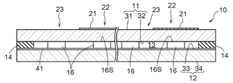
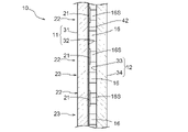
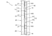
- FIG. 1 is an exploded perspective view showing a double glazing panel of a first embodiment; FIG. It is a longitudinal cross-sectional view of a multi-layer glass panel.
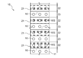
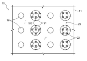
- 1 is a plan view of a multi-layer glass panel;
- FIG. FIG. 4 is a plan view of a double-glazed glass panel according to Modification 1 of the first embodiment;
- FIG. 5 is a plan view of a double-layered glass panel according to Modification 2 of the first embodiment;
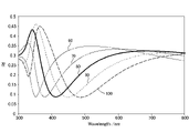
- 5 is a graph showing the relationship between the wavelength and the reflectance of the reflective film for each thickness of the reflective film.
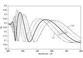
- 5 is a graph showing the relationship between the wavelength and the reflectance of the reflective film for each thickness of the reflective film.
- 5 is a graph showing the relationship between the wavelength and the reflectance of the reflective film for each thickness of the reflective film.
- 5 is a graph showing the relationship between the wavelength and the reflectance of the reflective film for each thickness of the reflective film.
- FIG. 10 is a vertical cross-sectional view of a multi-layer glass panel according to a second embodiment;
- FIG. 10 is a vertical cross-sectional view of a multi-layer glass panel according to a third embodiment;
- FIG. 11 is a vertical cross-sectional view of a multi-layer glass panel according to a fourth embodiment;
- FIG. 11 is a vertical cross-sectional view of a multi-layer glass panel according to a modified example of the fourth embodiment;
- FIG. 10 is a plan view of a multi-layer glass panel of another embodiment;
- FIG. 10 is a plan view of a multi-layer glass panel of another embodiment;
- FIG. 10 is a plan view of a multi-layer glass panel of another embodiment;
- FIG. 10 is a plan view of a multi-layer glass panel of another embodiment;
- a vacuum double-glazed glass panel (hereinafter abbreviated as “glass panel”) 10 includes a first glass plate 11 and a second glass plate facing the first glass plate 11. It comprises a plate 12 , a sealing portion 14 and a plurality of pillars 16 .
- the sealing portion 14 is provided around the outer edges of the first glass plate 11 and the second glass plate 12 .
- a plurality of columns 16 are arranged between the first glass plate 11 and the second glass plate 12 .
- the first glass plate 11 is float glass having a first surface 31 and a second surface 32 provided on the back side of the first surface 31 .
- the second glass plate 12 is a float glass having a third surface 33 facing the second surface 32 of the first glass plate 11 and a fourth surface 34 provided behind the third surface 33 .
- the first surface 31 of the first glass plate 11 is arranged on the outdoor side
- the fourth surface 34 of the second glass plate 12 is arranged on the indoor side.
- a gap 13 is formed between the first glass plate 11 and the second glass plate 12 at a predetermined interval, and the gap 13 is brought into a vacuum state (an example of a reduced pressure state) by the sealing portion 14. Hermetically sealed. Thereby, heat insulating performance can be imparted to the glass panel 10 .
- a plurality of columns 16 are interposed between the second surface 32 of the first glass plate 11 and the third surface 33 of the second glass plate 12 to A sealed portion 14 is formed over the entire periphery of the glass plates 11 and 12 while maintaining a predetermined distance from the third surface 33 .
- the sealing portion 14 is configured by a sealing material or the like.
- the first glass plate 11 is sucked and evacuated from a suction port (not shown). After the suction, the suction port is fused and sealed with low-melting-point glass or the like.
- the glass panel 10 may be sealed in a state where the air gap 13 is in a reduced pressure state than the atmospheric pressure.
- the multiple columns 16 contact the second surface 32 of the first glass plate 11 and the third surface 33 of the second glass plate 12 .
- the columnar body 16 is formed in a columnar shape, for example.
- the columnar body 16 is made of ceramic such as alumina or zirconia. Posts 16 may include nanoparticle fillers such as zirconia. By including zirconia in the columnar body 16, the thermal conductivity of the columnar body 16 can be reduced, and the heat resistance and strength can be easily improved.
- Materials for the pillars 16 include ceramic nanoparticles (Al 2 O 3 , SiO 2 , ZrO 2 , SiC, Si 3 N 4 and combinations thereof), ceramic precursors such as SSQ and polysilazanes, sintered ceramics (Al 2 O3, SiO2 , ZrO2 , SiC , Si3N4 , zircon, steatite, cordierite, aluminum titanate, etc.), glass ( silica, soda lime, borosilicate, etc.), glass ceramics (crystallized glass ), glass frits, glass beads or bubbles, metals (SUS304, SUS430, SUS410, iron, nickel, etc.), resins (polyimide, polyamide, PEEK, PTFE, etc.), and combinations thereof.
- ceramic precursors such as SSQ and polysilazanes
- sintered ceramics Al 2 O3, SiO2 , ZrO2 , SiC , Si3N4 , zircon, steatite
- the diameter of the contact surface of the column 16 between the second surface 32 of the first glass plate 11 and the third surface 33 of the second glass plate 12 is set to, for example, 100 ⁇ m or more and 1000 ⁇ m or less.
- Birds have excellent visual acuity, as their visual acuity is five times or more that of humans, and seven times or more depending on the species of bird. Therefore, even if it is difficult for humans to recognize the column 16, it is sufficiently possible for birds to recognize the column 16.
- the diameter of the contact surface between the second surface 32 and the third surface 33 of the columnar body 16 is 1000 ⁇ m or less, the heat transmission coefficient (U value) of the glass panel 10 is lowered, so that the glass panel 10 has a heat insulating property. can be improved.
- the first surface 31 of the first glass plate 11 includes a reflective area 22 provided with a reflective film 21 having a function of reflecting ultraviolet rays, and a transmissive area 23 having a function of transmitting ultraviolet rays. .
- the reflective area 22 is composed of a plurality of reflective films 21, and each reflective film 21 is formed in a strip shape. As shown in FIGS. 1 to 3, in this embodiment, the reflective film 21 extends in the gravitational direction (vertical direction in FIG. 3), and the plurality of reflective films 21 extends in the horizontal direction (vertical direction in FIG. 3) orthogonal to the gravitational direction. 3) are provided at predetermined intervals.
- the transmissive region 23 is a region of the first surface 31 of the first glass plate 11 where the reflective film 21 is not formed.
- the reflective film 21 is configured by laminating a plurality of layers, for example.
- the laminated layers may contain tin oxide (SnO 2 ) or silicon oxide (SiO 2 ).
- the first layer is tin oxide
- the second layer is silicon oxide
- the third layer is fluorine-doped tin oxide (F: SnO 2 )
- the fourth layer is Silicon oxide layers may be laminated in order.
- the thickness of the tin oxide of the first layer is 5 nm to 100 nm (" ⁇ " means "more than or equal to" including the lower limit and the upper limit, and the same shall apply hereinafter), preferably 10 nm to 50 nm, more preferably 10 nm to 20 nm.
- the thickness of the silicon oxide of the second layer is 5 nm to 100 nm, preferably 10 nm to 50 nm, more preferably 15 nm to 30 nm.
- the thickness of the fluorine-doped tin oxide of the third layer is between 5 nm and 200 nm, preferably between 50 nm and 150 nm, more preferably between 100 nm and 120 nm.
- the thickness of the silicon oxide of the fourth layer is 5 nm to 200 nm, preferably 50 nm to 150 nm, more preferably 80 nm to 100 nm.
- the reflective film 21 may be composed of at least one layer from the first layer to the fourth layer.
- the reflective film 21 may contain titanium dioxide (TiO 2 ).
- the thickness of titanium dioxide is 10 nm to 100 nm, more preferably 10 nm to 50 nm.
- the reflective film 21 may be a single layer of titanium oxide.
- the reflective film 21 can be formed using magnetron sputtering, CVD, PCVD, sol-gel methods, or other thin film deposition techniques.
- the reflective film 21 includes, for example, SnO 2 (first layer), SiO 2 (second layer), F:SnO 2 (third layer), and SiO 2 (fourth layer) on the first surface 31 of the first glass plate 11 . layer) and TiO 2 may be laminated in order.
- the thickness of the reflective film 21 is set to, for example, 10 nm or more and 200 nm or less.
- the first surface 31 of the first glass plate 11 of the glass panel 10 is provided with a reflective region 22 that reflects ultraviolet rays and a transmissive region 23 that transmits ultraviolet rays. Furthermore, a plurality of columns 16 are arranged between the first glass plate 11 and the second glass plate 12 . Due to the reflective area 22 and the transmissive area 23, it is more likely that nature reflected in the reflective area 22 of the first glass plate 11 and indoor plants and the like that can be seen through the glass plates 11 and 12 are mixed in the field of view of the bird. In addition, the existence of the plurality of pillars 16 increases the possibility of birds recognizing the glass panel 10 as an artifact. As a result, it is possible to prevent birds from colliding with the glass panel 10 . In particular, since ultraviolet rays have wavelengths that can be seen by birds but not by humans, the ability of birds to recognize the glass panel 10 is enhanced by providing the glass panel 10 with a reflective film 21 having a function of reflecting ultraviolet rays. be able to.
- the reflective film 21 is formed on the first surface 31 in a stripe shape.
- the reflective area 22 is formed by arranging a plurality of reflective films 21 at predetermined intervals in the horizontal direction (horizontal direction) of the first glass plate 11 .
- the width of the reflective region 22 may be 1 cm or more, preferably 5 cm or more, and more preferably 10 cm or more.
- a plurality of reflective films 21 are preferably arranged at intervals of 3 cm or more and 20 cm or less (intervals between opposing outer lines of adjacent reflective films 21), and the intervals are 5 cm or more and 10 cm or less.
- the maximum width of the transmissive region 23 is 3 cm or more and 20 cm or less, preferably 5 cm or more and 10 cm or less. If the maximum width of the transmissive region 23 is 3 cm or more and 20 cm or less, the nature reflected in the reflective region 22 of the first glass plate 11 and the indoor plants etc. that can be seen through the glass plates 11 and 12 can be surely mixed. It is possible to create. In addition, if the maximum width of the transmissive region 23 is 5 cm or more and 10 cm or less, the width should be set to a width at which birds tend to pass through the transmissive region 23 (for example, the width in the direction of gravity is 5 cm and the width in the horizontal direction is 10 cm) or less. , and the bird collision prevention function of the glass panel 10 can be improved.
- At least one of the plurality of pillars 16 has a region 16S that overlaps with the reflective film 21 when viewed in a direction perpendicular to the first surface 31 .
- the contact surfaces with the glass plates 11 and 12 overlap the reflective film 21 in about one-third of the plurality of columns 16 .
- the glass panel 10 has a first reflection portion (“A” in FIG. 3 ) of only the reflection area 22 (reflection film 21 ) as a portion where light is reflected.
- the first reflection portion (A) reflects strong ultraviolet light having a wavelength of around 370 nm.
- the second reflecting portion (B) the strong ultraviolet rays and the visible light reflected by the pillars 16 are reflected.
- the third reflecting portion (C) the weak ultraviolet rays and the visible light reflected by the pillars 16 are reflected.
- the fourth reflecting portion (D) reflects weak ultraviolet rays. It should be noted that the difference in the reflected light due to the four types of reflection portions (A to D) is different from the intensity of the reflected light brightness based on the film thickness difference of the reflective film 21 in the reflective region 22, which will be described later.
- the plurality of columns 16 are arranged at equal intervals, and the reflection region 22 has a plurality of reflection films 21 arranged at predetermined intervals. It is arranged and formed every. However, the interval between the adjacent reflective films 21 is different from the interval between the centers of the adjacent columns 16 . Specifically, the intervals between the plurality of reflective films 21 are larger than the intervals between the centers of the plurality of pillars 16 .
- the plurality of pillars 16 are arranged at regular intervals and the plurality of reflective films 21 are arranged at intervals different from those of the plurality of pillars 16 as in the present embodiment, the four types of reflection portions become complicated. Therefore, the bird collision prevention function against the glass panel 10 can be further improved.
- the plurality of pillars 16 are arranged at equal intervals in the glass panel 10 while being in contact with the second surface 32 and the third surface 33, and the distance between the centers of the adjacent pillars 16 is, for example, 3 cm or more and 20 cm. It is below.
- a heat insulating film 41 having a function of reflecting far-infrared rays is arranged on the entire surface of the third surface 33 of the second glass plate 12.
- the heat insulating film 41 can be composed of, for example, a Low-E film.
- the Low-E film is composed of a single metal layer, or a multi-layer stack of two or more layers selected from a metal layer, a metal oxide layer, a metal nitride layer and a metal oxynitride layer.
- Suitable examples of metal layers include silver layers.
- Suitable examples of metal oxide layers include tin oxide layers, titanium oxide layers and zinc oxide layers.
- Suitable examples of metal nitride layers include silicon nitride.
- Suitable examples of metal oxynitride layers include silicon oxynitride.
- the Low-E film is preferably formed by a vacuum film formation method such as a physical vapor deposition method (PVD), and is particularly preferred by a sputtering method because a film can be uniformly formed over a large area.
- PVD physical vapor deposition method
- the heat in the room can be prevented from escaping outside by the second glass plate 12, and the heat insulation can be improved.
- the reflective area 22 on the first surface 31 of the first glass plate 11 it becomes easier for birds to recognize the reflective area 22 on the glass panel 10 , and it is possible to further prevent birds from colliding with the glass panel 10 .
- the glass plate can be made more efficient than the case where the reflective film 21 and the heat insulating film 41 are provided on one glass plate. Yield can be improved.
- the glass panel 10 has a plurality of reflective films 21 arranged at intervals in the direction of gravity in the reflective area 22 .
- the plurality of reflective films 21 in the reflective region 22 are arranged at intervals of, for example, 3 cm or more and 20 cm or less.
- the maximum width of the transmissive region 23 is 3 cm or more and 20 cm or less. If the maximum width of the transmissive region 23 is 3 cm or more and 20 cm or less, the glass panel 10 can improve the bird's collision prevention function.
- the plurality of reflective films 21 may be arranged to cross each other.
- a plurality of reflecting films 21 extending in the horizontal direction (horizontal direction) and a plurality of reflecting films 21 extending in the gravitational direction (vertical direction) intersect to form a reflecting area 22 in a grid pattern.
- the transmissive area 23 can be set to a width less than 10 cm where birds tend to pass through (for example, the horizontal width is 10 cm). can be set to less than a certain vertical width (for example, the width in the direction of gravity is 5 cm). As a result, the bird collision prevention function of the glass panel 10 can be further improved.
- the plurality of columns 16 in contact with the second surface 32 and the third surface 33 are columns that overlap the reflection area 22 when viewed in a direction perpendicular to the first surface 31 .
- the sum of the 16 contact areas is 50% or more of the total contact area of the plurality of columns 16 .
- the reflective area 22 has a lower UV transmittance and a higher UV reflectance than the transmissive area 23 . Similarly, it is known that the near-infrared transmittance in the reflective region 22 is low. Therefore, in the glass panel 10 , the reflective area 22 tends to be at a lower temperature than the transmissive area 23 .
- the contact area of the pillars 16 overlapping the reflective region 22 having a relatively low temperature is set to 50% or more of the total contact area of the plurality of pillars 16 .
- the heat transmission coefficient (U value) can be reduced, and the heat insulation performance can be maintained.
- the glass panel 10 has a smaller amount of heat in the regions of the glass plates 11 and 12 where the pillars 16 overlapping the reflection region 22 are present, so heat transfer via the pillars 16 is further suppressed. can do. As a result, in the glass panel 10, the heat transmission coefficient (U value) can be reduced, and the heat insulation performance can be maintained.
- a reflective film 21 having a thickness of 0 to 200 nm (10 nm steps) was placed on the surface of a glass plate having a thickness of 3.1 mm, and changes in reflectance (Rf) at wavelengths (Wavelength) of 300 nm to 800 nm were measured.
- a single layer of TiO 2 was used as the reflective film 21 .
- 6 to 9 show the measurement results of the reflectance (Rf), and the numerical values in the lead lines indicate the thickness (nm) of the reflective film 21.
- the reflectance is 0.0. was about 1.
- the reflective film 21 had a thickness of 10 nm to 200 nm, a reflectance of 0.3 or higher was obtained at a wavelength of 300 nm to 400 nm (ultraviolet region).
- the thickness of the reflective film 21 may be 10 nm or more and 50 nm or less.
- the reflective area 22 can have a higher UV reflectance than the transmissive area 23 even if the thickness of the reflective film 21 is small. As a result, the ability of birds to recognize the glass panel 10 can be enhanced while suppressing the manufacturing cost of the glass panel 10 .
- the thickness of the reflective film 21 may be 60 nm or more and 100 nm or less.
- the reflective region 22 has reflectance not only in the ultraviolet region (wavelength 300 nm to 400 nm) but also in the visible region (wavelength 400 nm to 780 nm) other than the ultraviolet region. becomes higher. That is, the reflective area 22 has higher reflectance for ultraviolet light and higher reflectance for visible light than the transmissive area 23 . As a result, the brightness of the reflected light in the reflective area 22 of the glass panel 10 is improved. , and the difference in reflected light from the four reflection sites (A to D).
- the thickness of the reflective film 21 may be 140 nm or more and 200 nm or less.
- the reflective region 22 has reflectance not only in the ultraviolet region (wavelength 300 nm to 400 nm) but also in the visible region (wavelength 400 nm to 780 nm) other than the ultraviolet region. becomes higher.
- the thickness of the reflective film 21 is set to 140 nm or more and 200 nm or less, the peak of the reflectance is clearly divided between the ultraviolet region and the visible region.
- Cheap That is, the reflective area 22 has higher reflectance for ultraviolet light and higher reflectance for visible light than the transmissive area 23 . As a result, the brightness of the reflected light in the reflection area 22 of the glass panel 10 is improved, so that the bird's ability to recognize the glass panel 10 can be enhanced.
- the glass panel 10 has a plurality of reflective films 21, which are the reflective regions 22, arranged on the second surface 32 of the first glass plate 11, and a low heat insulating film 41 as the heat insulating film 41.
- the -E film is arranged on the entire surface of the third surface 33 of the second glass plate 12 .
- the heat-insulating film 41 on the third surface 33 of the glass panel 10 as in the present embodiment, the heat-insulating property of the glass panel 10 can be improved without escaping indoor heat to the outside. Moreover, in the glass panel 10, since the reflective film 21 is not exposed to the outside air by providing the reflective area 22 on the second surface 32, the weather resistance of the reflective area 22 can be enhanced. Furthermore, since the reflective film 21 is provided on the first glass plate 11 and the heat insulating film 41 is provided on the second glass plate 12, compared to the case where the reflective film 21 and the heat insulating film 41 are provided on one glass plate, the glass The yield of the board can be improved.
- a Low-E film is disposed on the entire surface of the second surface 32 of the first glass plate 11 as a heat shield film 42 having a function of reflecting near-infrared rays. are arranged on the third surface 33 of the second glass plate 12 .
- the heat shielding film 42 By providing the heat shielding film 42 on the second surface 32 of the glass panel 10 as in the present embodiment, heat from the outside of the glass panel 10 is less likely to be transmitted to the interior of the room. can be done. Moreover, since the reflective film 21 is not exposed to the outside air by providing the reflective area 22 on the third surface 33 of the glass panel 10, the weather resistance of the reflective area 22 can be enhanced. Furthermore, since the heat shielding film 42 is provided on the first glass plate 11 and the reflecting film 21 is provided on the second glass plate 12, the heat shielding film 42 is provided on one glass plate. , the yield of the glass plate can be improved.
- the Low-E film as the heat shield film 42 is arranged on the entire surface of the second surface 32 of the first glass plate 11, and the reflective film 21 is the heat shield film 42. It is arranged so that it overlaps with the surface side.
- the second surface 32 is provided with the heat shield film 42, the heat from the outside is not easily transmitted to the inside of the room, and the heat shielding property can be improved.
- the reflective area 22 is provided on the second surface 32 , the reflective area 22 is arranged at a position close to the outdoor side, so that the ability of birds to recognize the glass panel 10 can be enhanced.
- the glass plates 11 and 12 have a plurality of belt-shaped reflective films 21 extending in the gravitational direction (vertical direction) or in the horizontal direction (horizontal direction).
- the plurality of reflective films 21 may extend in an oblique direction intersecting the gravitational direction (up-down direction) and the horizontal direction (left-right direction).
- the region 16S overlapping the reflective film 21 in the columnar body 16 may be a partial region of the columnar body 16 . Further, as shown in FIG. 14 , the interval between adjacent reflective films 21 in a plurality of reflective films 21 may be narrower than the interval between adjacent pillars 16 in a plurality of pillars 16 .
- the plurality of reflective films 21 may be formed in dot shapes on the plate surfaces of the glass plates 11 and 12 .
- the intervals between the plurality of reflecting films 21 may be the same as or different from the intervals between the plurality of pillars 16 .
- the reflective areas 22 can be provided in the minimum necessary range, and the manufacturing cost of the glass panel 10 can be reduced.
- the center spacing of the plurality of reflective films 21 is configured to be larger than the center spacing of the plurality of pillars 16 .
- FIG. 15 the center spacing of the plurality of reflective films 21 is configured to be larger than the center spacing of the plurality of pillars 16 .
- the reflective films 21 are formed in a dot shape, and the center intervals of the plurality of reflective films 21 are configured to be smaller than the center intervals of the plurality of columnar bodies 16 .
- the plurality of pillars 16 some overlap the reflective film 21 as a whole and some overlap the reflective film 21 partially.
- the plurality of reflective films 21 may have a dot shape and a stripe shape combined.
- a reflective area 22 may be provided in the .
- the glass plates 11 and 12 show an example in which the reflection regions 22 are formed by arranging the plurality of reflection films 21 at regular intervals. It does not have to be an interval.
- the shape of the columnar body 16 is cylindrical.
- an antireflection film may be arranged in the transmissive regions 23 of the glass plates 11 and 12 .
- the present invention can be widely used for multi-layer glass panels.
Landscapes
- Engineering & Computer Science (AREA)
- Structural Engineering (AREA)
- Civil Engineering (AREA)
- Chemical & Material Sciences (AREA)
- Life Sciences & Earth Sciences (AREA)
- Physics & Mathematics (AREA)
- General Physics & Mathematics (AREA)
- Optics & Photonics (AREA)
- Organic Chemistry (AREA)
- Chemical Kinetics & Catalysis (AREA)
- General Chemical & Material Sciences (AREA)
- Geochemistry & Mineralogy (AREA)
- Materials Engineering (AREA)
- Health & Medical Sciences (AREA)
- Architecture (AREA)
- Toxicology (AREA)
- Ceramic Engineering (AREA)
- Environmental Sciences (AREA)
- Zoology (AREA)
- Wood Science & Technology (AREA)
- Pest Control & Pesticides (AREA)
- Insects & Arthropods (AREA)
- Birds (AREA)
- Joining Of Glass To Other Materials (AREA)
- Catching Or Destruction (AREA)
Abstract
Description
以下、第1実施形態に係る減圧複層ガラスパネルについて図面を参照しながら説明する。
図4に示されるように、ガラスパネル10は、反射領域22において複数の反射膜21が重力方向に間隔を空けて配置されている。図4に示される例においても、反射領域22における複数の反射膜21は、例えば3cm以上20cm以下の間隔で配置されている。これにより、透過領域23の最大幅は、3cm以上20cm以下となる。透過領域23の最大幅を3cm以上20cm以下とすれば、ガラスパネル10において鳥の衝突防止機能を向上させることができる。
ガラスパネル10において、複数の反射膜21は交差して配置されていてもよい。図5に示される例では、水平方向(左右方向)に延びる複数の反射膜21と重力方向(上下方向)に延びる複数の反射膜21とが交差し、反射領域22が格子状に形成されている。反射領域22が格子状であることで、透過領域23を鳥が通過する習性のある横幅(例えば水平方向の幅が10cm)未満に設定することができるとともに、透過領域23を鳥が通過する習性のある縦幅(例えば重力方向の幅が5cm)未満に設定することができる。その結果、ガラスパネル10において鳥の衝突防止機能をより向上させることができる。
上述の第1実施形態の変形例2では、第1面31と垂直な方向視において、反射領域22と重複する柱体16の接触面積の合計が、複数の柱体16の総接触面積の50%以上である例を示したが、反射領域22と重複する柱体16の接触面積の合計は、複数の柱体16の総接触面積の20%以上であってもよい。
厚さ3.1mmのガラス板の表面に、0~200nmの厚み(10nm刻み)の反射膜21を配置し、夫々について波長(Wavelength)300nm~800nmにおける反射率(Rf)の変化を計測した。反射膜21としてTiO2の単層を用いた。図6~図9に反射率(Rf)の計測結果を示し、引出線の数値は反射膜21の厚み(nm)を示す。
第2実施形態では、図10に示されるように、ガラスパネル10は、反射領域22である複数の反射膜21が第1ガラス板11の第2面32に配置され、断熱膜41としてのLow-E膜が第2ガラス板12の第3面33の全面に配置されている。
第3実施形態では、図11に示されるように、近赤外線の反射機能を有する遮熱膜42としてLow-E膜が第1ガラス板11の第2面32の全面に配置され、反射領域22である複数の反射膜21が第2ガラス板12の第3面33に配置されている。
第4実施形態では、図12に示されるように、遮熱膜42としてのLow-E膜が第1ガラス板11の第2面32に全面に配置され、反射膜21は遮熱膜42の表面側に重なるように配置されている。
本変形例では、図13に示されるように、反射膜21が第1ガラス板11の第2面32に配置され、遮熱膜42としてのLow-E膜が、第1ガラス板11の第2面32の全面であって複数の反射膜21の表面側を覆う形態で配置されている。これにより、反射領域22は、柱体16との間に遮熱膜42が介在した状態で配置されるため、柱体16との接触による反射領域22の損傷を防止することができる。なお、この構成を第3面33に適用してもよい。
(1)上記の実施形態では、ガラス板11,12において、帯状の複数の反射膜21が重力方向(上下方向)または水平方向(左右方向)に延設される例を示したが、帯状の複数の反射膜21は、重力方向(上下方向)及び水平方向(左右方向)に交差する斜め方向に延設されていてもよい。
11 :第1ガラス板
12 :第2ガラス板
13 :空隙部
14 :密閉部
16 :柱体
16S :領域
21 :反射膜
22 :反射領域
23 :透過領域
31 :第1面
32 :第2面
33 :第3面
34 :第4面
41 :断熱膜
42 :遮熱膜
Claims (17)
- 室外側に配置可能な第1面と、前記第1面の裏側に設けられる第2面とを有する第1ガラス板と、
前記第2面に対向する第3面と、前記第3面の裏側に設けられる第4面とを有する第2ガラス板と、
前記第2面及び前記第3面に接触する複数の柱体と、を備え、
前記第1面、前記第2面、前記第3面及び前記第4面の少なくとも何れか1つは、紫外線に対して反射機能を有する反射膜が設けられた反射領域と、前記紫外線に対して透過機能を有する透過領域と、を含んでおり、
複数の前記柱体の少なくとも1つは、前記第1面と垂直な方向視において、前記反射膜と重複する領域を有している複層ガラスパネル。 - 前記反射領域は、複数の前記反射膜が所定間隔毎に配置されて形成され、
前記透過領域の最大幅が3cm以上20cm以下である請求項1に記載の複層ガラスパネル。 - 複数の前記柱体は、等間隔で配置されており、
隣り合う夫々の前記柱体の中心間隔は、3cm以上20cm以下である請求項1または2に記載の複層ガラスパネル。 - 複数の前記柱体は、等間隔に配置されており、
前記反射領域は、複数の前記反射膜が所定間隔毎に配置されて形成され、
隣り合う夫々の前記反射膜の間隔は、隣り合う夫々の前記柱体の中心間隔とは異なる請求項1から3のいずれか一項に記載の複層ガラスパネル。 - 前記反射膜は、ストライプ形状である請求項1から4のいずれか一項に記載の複層ガラスパネル。
- 前記反射膜は、ドット形状である請求項1から5のいずれか一項に記載の複層ガラスパネル。
- 前記反射膜は、酸化チタンを含んでいる請求項1から6のいずれか一項に記載の複層ガラスパネル。
- 前記反射膜の厚みは、10nm以上50nm以下である請求項7に記載の複層ガラスパネル。
- 前記反射膜の厚みは、60nm以上100nm以下である請求項7に記載の複層ガラスパネル。
- 前記反射膜の厚みは、140nm以上200nm以下である請求項7に記載の複層ガラスパネル。
- 前記第1ガラス板及び前記第2ガラス板の外縁全周に設けられ、前記第1ガラス板と前記第2ガラス板との間に減圧状態に密閉された空隙部を形成する密閉部を更に備えた請求項1から10のいずれか一項に記載の複層ガラスパネル。
- 前記第2面及び前記第3面に接触する複数の前記柱体は、前記第1面と垂直な方向視において、前記反射領域と重複する前記柱体の接触面積の合計が、複数の前記柱体の総接触面積の20%以上である請求項1から11のいずれか一項に記載の複層ガラスパネル。
- 前記第2面及び前記第3面に接触する複数の前記柱体は、前記第1面と垂直な方向視において、前記反射領域と重複する前記柱体の接触面積の合計が、複数の前記柱体の総接触面積の50%以上である請求項1から11のいずれか一項に記載の複層ガラスパネル。
- 前記第3面には、遠赤外線の反射機能を有する断熱膜が積層されており、
前記第1面は、前記反射領域及び前記透過領域を含んでいる請求項1から13のいずれか一項に記載の複層ガラスパネル。 - 前記第3面には、遠赤外線の反射機能を有する断熱膜が積層されており、
前記第2面は、前記反射領域及び前記透過領域を含んでいる請求項1から13のいずれか一項に記載の複層ガラスパネル。 - 前記第2面には、近赤外線の反射機能を有する遮熱膜が積層されており、
前記第3面は、前記反射領域及び前記透過領域を含んでいる請求項1から13のいずれか一項に記載の複層ガラスパネル。 - 鳥の衝突を防止するために用いられる請求項1から16のいずれか一項に記載の複層ガラスパネル。
Priority Applications (4)
| Application Number | Priority Date | Filing Date | Title |
|---|---|---|---|
| CN202280025795.4A CN117120391A (zh) | 2021-03-29 | 2022-03-22 | 多层玻璃面板 |
| US18/274,417 US20240093550A1 (en) | 2021-03-29 | 2022-03-22 | Multi-glazed panel |
| JP2023511003A JPWO2022210073A1 (ja) | 2021-03-29 | 2022-03-22 | |
| EP22780288.1A EP4317101A4 (en) | 2021-03-29 | 2022-03-22 | DOUBLE GLASS |
Applications Claiming Priority (2)
| Application Number | Priority Date | Filing Date | Title |
|---|---|---|---|
| JP2021-056150 | 2021-03-29 | ||
| JP2021056150 | 2021-03-29 |
Publications (1)
| Publication Number | Publication Date |
|---|---|
| WO2022210073A1 true WO2022210073A1 (ja) | 2022-10-06 |
Family
ID=83455252
Family Applications (1)
| Application Number | Title | Priority Date | Filing Date |
|---|---|---|---|
| PCT/JP2022/013036 Ceased WO2022210073A1 (ja) | 2021-03-29 | 2022-03-22 | 複層ガラスパネル |
Country Status (5)
| Country | Link |
|---|---|
| US (1) | US20240093550A1 (ja) |
| EP (1) | EP4317101A4 (ja) |
| JP (1) | JPWO2022210073A1 (ja) |
| CN (1) | CN117120391A (ja) |
| WO (1) | WO2022210073A1 (ja) |
Cited By (1)
| Publication number | Priority date | Publication date | Assignee | Title |
|---|---|---|---|---|
| DE102022134997A1 (de) * | 2022-12-29 | 2024-07-04 | Seen Ag | Mehrscheiben-Glas- oder -Isolierglas-Sichtelement, insbesondere Fenster- und/oder Fassadenelement, Herstellungsverfahren und eine Verwendung des Mehrscheiben-Glas- oder -Isolierglas Sichtelements |
Citations (5)
| Publication number | Priority date | Publication date | Assignee | Title |
|---|---|---|---|---|
| US20140168760A1 (en) * | 2012-12-17 | 2014-06-19 | Guardian Industries Corp. | Window for reducing bird collisions |
| JP2016520033A (ja) * | 2013-05-24 | 2016-07-11 | ピルキントン グループ リミテッド | 板ガラス |
| WO2017056418A1 (ja) * | 2015-09-29 | 2017-04-06 | パナソニックIpマネジメント株式会社 | ガラスパネルユニット,これを備えたガラス窓、及びガラスパネルユニットの製造方法 |
| JP2017524629A (ja) * | 2014-05-27 | 2017-08-31 | サントル・ルクセンブルジョワ・ドゥ・ルシェルシュ・プール・ル・ベール・エ・ラ・セラミック(シーアールブイシー)エスエイアールエルCentre Luxembourgeois de Recherches pour le Verre et la Ceramique (C.R.V.C.) SARL | 鳥の衝突防止用ig窓ユニット |
| JP2017525640A (ja) * | 2014-05-28 | 2017-09-07 | ピルキントン グループ リミテッド | 板ガラス |
Family Cites Families (3)
| Publication number | Priority date | Publication date | Assignee | Title |
|---|---|---|---|---|
| FR2889886A1 (fr) * | 2005-08-19 | 2007-02-23 | Saint Gobain | Lampe uv plane a decharge coplanaire et utilisations |
| PL3357885T3 (pl) * | 2015-09-29 | 2020-06-29 | Panasonic Intellectual Property Management Co., Ltd. | Zespół paneli szklanych i okno szklane |
| JP6861614B2 (ja) * | 2017-03-28 | 2021-04-21 | 大阪瓦斯株式会社 | 放射冷却装置および放射冷却方法 |
-
2022
- 2022-03-22 WO PCT/JP2022/013036 patent/WO2022210073A1/ja not_active Ceased
- 2022-03-22 US US18/274,417 patent/US20240093550A1/en active Pending
- 2022-03-22 JP JP2023511003A patent/JPWO2022210073A1/ja active Pending
- 2022-03-22 EP EP22780288.1A patent/EP4317101A4/en active Pending
- 2022-03-22 CN CN202280025795.4A patent/CN117120391A/zh active Pending
Patent Citations (5)
| Publication number | Priority date | Publication date | Assignee | Title |
|---|---|---|---|---|
| US20140168760A1 (en) * | 2012-12-17 | 2014-06-19 | Guardian Industries Corp. | Window for reducing bird collisions |
| JP2016520033A (ja) * | 2013-05-24 | 2016-07-11 | ピルキントン グループ リミテッド | 板ガラス |
| JP2017524629A (ja) * | 2014-05-27 | 2017-08-31 | サントル・ルクセンブルジョワ・ドゥ・ルシェルシュ・プール・ル・ベール・エ・ラ・セラミック(シーアールブイシー)エスエイアールエルCentre Luxembourgeois de Recherches pour le Verre et la Ceramique (C.R.V.C.) SARL | 鳥の衝突防止用ig窓ユニット |
| JP2017525640A (ja) * | 2014-05-28 | 2017-09-07 | ピルキントン グループ リミテッド | 板ガラス |
| WO2017056418A1 (ja) * | 2015-09-29 | 2017-04-06 | パナソニックIpマネジメント株式会社 | ガラスパネルユニット,これを備えたガラス窓、及びガラスパネルユニットの製造方法 |
Non-Patent Citations (1)
| Title |
|---|
| See also references of EP4317101A4 |
Cited By (1)
| Publication number | Priority date | Publication date | Assignee | Title |
|---|---|---|---|---|
| DE102022134997A1 (de) * | 2022-12-29 | 2024-07-04 | Seen Ag | Mehrscheiben-Glas- oder -Isolierglas-Sichtelement, insbesondere Fenster- und/oder Fassadenelement, Herstellungsverfahren und eine Verwendung des Mehrscheiben-Glas- oder -Isolierglas Sichtelements |
Also Published As
| Publication number | Publication date |
|---|---|
| EP4317101A4 (en) | 2025-03-19 |
| JPWO2022210073A1 (ja) | 2022-10-06 |
| EP4317101A1 (en) | 2024-02-07 |
| US20240093550A1 (en) | 2024-03-21 |
| CN117120391A (zh) | 2023-11-24 |
Similar Documents
| Publication | Publication Date | Title |
|---|---|---|
| CN107429538B (zh) | 用于防止鸟类碰撞的绝缘玻璃窗单元 | |
| EP3684613B1 (en) | Ig window unit including laminated substrates for preventing bird collisions | |
| JP6450747B2 (ja) | 板ガラス | |
| US11841519B2 (en) | Window unit having UV reflecting coating with high contrast ratio at large viewing angles for reducing bird collisions | |
| RU2639750C2 (ru) | Изолирующие стеклопакеты с низкоэмиссионными и антиотражающими покрытиями | |
| US20240253330A1 (en) | Glazing for preventing bird collisions | |
| JP2017525640A (ja) | 板ガラス | |
| RU2754898C2 (ru) | Оконный блок-стеклопакет с тройным серебряным покрытием и диэлектрическим покрытием на противоположных сторонах стеклянной подложки | |
| EP3383814B1 (en) | Laser welding transparent glass panes using a low emissivity coating | |
| JP7788240B2 (ja) | ガラス体 | |
| US12110252B2 (en) | Low-e coated architectural glass having high selectivity | |
| US20240093550A1 (en) | Multi-glazed panel |
Legal Events
| Date | Code | Title | Description |
|---|---|---|---|
| 121 | Ep: the epo has been informed by wipo that ep was designated in this application |
Ref document number: 22780288 Country of ref document: EP Kind code of ref document: A1 |
|
| ENP | Entry into the national phase |
Ref document number: 2023511003 Country of ref document: JP Kind code of ref document: A |
|
| WWE | Wipo information: entry into national phase |
Ref document number: 18274417 Country of ref document: US |
|
| WWE | Wipo information: entry into national phase |
Ref document number: 2022780288 Country of ref document: EP |
|
| NENP | Non-entry into the national phase |
Ref country code: DE |
|
| ENP | Entry into the national phase |
Ref document number: 2022780288 Country of ref document: EP Effective date: 20231030 |