WO2022210181A1 - マット材、排ガス浄化装置及びマット材の製造方法 - Google Patents
マット材、排ガス浄化装置及びマット材の製造方法 Download PDFInfo
- Publication number
- WO2022210181A1 WO2022210181A1 PCT/JP2022/013606 JP2022013606W WO2022210181A1 WO 2022210181 A1 WO2022210181 A1 WO 2022210181A1 JP 2022013606 W JP2022013606 W JP 2022013606W WO 2022210181 A1 WO2022210181 A1 WO 2022210181A1
- Authority
- WO
- WIPO (PCT)
- Prior art keywords
- mat material
- inorganic
- mat
- binder
- inorganic fibers
- Prior art date
- Legal status (The legal status is an assumption and is not a legal conclusion. Google has not performed a legal analysis and makes no representation as to the accuracy of the status listed.)
- Ceased
Links
Images


Classifications
-
- F—MECHANICAL ENGINEERING; LIGHTING; HEATING; WEAPONS; BLASTING
- F01—MACHINES OR ENGINES IN GENERAL; ENGINE PLANTS IN GENERAL; STEAM ENGINES
- F01N—GAS-FLOW SILENCERS OR EXHAUST APPARATUS FOR MACHINES OR ENGINES IN GENERAL; GAS-FLOW SILENCERS OR EXHAUST APPARATUS FOR INTERNAL-COMBUSTION ENGINES
- F01N3/00—Exhaust or silencing apparatus having means for purifying, rendering innocuous, or otherwise treating exhaust
- F01N3/08—Exhaust or silencing apparatus having means for purifying, rendering innocuous, or otherwise treating exhaust for rendering innocuous
- F01N3/10—Exhaust or silencing apparatus having means for purifying, rendering innocuous, or otherwise treating exhaust for rendering innocuous by thermal or catalytic conversion of noxious components of exhaust
- F01N3/24—Exhaust or silencing apparatus having means for purifying, rendering innocuous, or otherwise treating exhaust for rendering innocuous by thermal or catalytic conversion of noxious components of exhaust characterised by constructional aspects of converting apparatus
- F01N3/28—Construction of catalytic reactors
- F01N3/2839—Arrangements for mounting catalyst support in housing, e.g. with means for compensating thermal expansion or vibration
- F01N3/2853—Arrangements for mounting catalyst support in housing, e.g. with means for compensating thermal expansion or vibration using mats or gaskets between catalyst body and housing
-
- F—MECHANICAL ENGINEERING; LIGHTING; HEATING; WEAPONS; BLASTING
- F01—MACHINES OR ENGINES IN GENERAL; ENGINE PLANTS IN GENERAL; STEAM ENGINES
- F01N—GAS-FLOW SILENCERS OR EXHAUST APPARATUS FOR MACHINES OR ENGINES IN GENERAL; GAS-FLOW SILENCERS OR EXHAUST APPARATUS FOR INTERNAL-COMBUSTION ENGINES
- F01N3/00—Exhaust or silencing apparatus having means for purifying, rendering innocuous, or otherwise treating exhaust
- F01N3/08—Exhaust or silencing apparatus having means for purifying, rendering innocuous, or otherwise treating exhaust for rendering innocuous
- F01N3/10—Exhaust or silencing apparatus having means for purifying, rendering innocuous, or otherwise treating exhaust for rendering innocuous by thermal or catalytic conversion of noxious components of exhaust
- F01N3/24—Exhaust or silencing apparatus having means for purifying, rendering innocuous, or otherwise treating exhaust for rendering innocuous by thermal or catalytic conversion of noxious components of exhaust characterised by constructional aspects of converting apparatus
- F01N3/28—Construction of catalytic reactors
- F01N3/2803—Construction of catalytic reactors characterised by structure, by material or by manufacturing of catalyst support
- F01N3/2835—Construction of catalytic reactors characterised by structure, by material or by manufacturing of catalyst support fibrous
-
- B—PERFORMING OPERATIONS; TRANSPORTING
- B01—PHYSICAL OR CHEMICAL PROCESSES OR APPARATUS IN GENERAL
- B01D—SEPARATION
- B01D53/00—Separation of gases or vapours; Recovering vapours of volatile solvents from gases; Chemical or biological purification of waste gases, e.g. engine exhaust gases, smoke, fumes, flue gases, aerosols
- B01D53/34—Chemical or biological purification of waste gases
- B01D53/74—General processes for purification of waste gases; Apparatus or devices specially adapted therefor
- B01D53/86—Catalytic processes
- B01D53/88—Handling or mounting catalysts
-
- C—CHEMISTRY; METALLURGY
- C04—CEMENTS; CONCRETE; ARTIFICIAL STONE; CERAMICS; REFRACTORIES
- C04B—LIME, MAGNESIA; SLAG; CEMENTS; COMPOSITIONS THEREOF, e.g. MORTARS, CONCRETE OR LIKE BUILDING MATERIALS; ARTIFICIAL STONE; CERAMICS; REFRACTORIES; TREATMENT OF NATURAL STONE
- C04B28/00—Compositions of mortars, concrete or artificial stone, containing inorganic binders or the reaction product of an inorganic and an organic binder, e.g. polycarboxylate cements
- C04B28/24—Compositions of mortars, concrete or artificial stone, containing inorganic binders or the reaction product of an inorganic and an organic binder, e.g. polycarboxylate cements containing alkyl, ammonium or metal silicates; containing silica sols
-
- D—TEXTILES; PAPER
- D04—BRAIDING; LACE-MAKING; KNITTING; TRIMMINGS; NON-WOVEN FABRICS
- D04H—MAKING TEXTILE FABRICS, e.g. FROM FIBRES OR FILAMENTARY MATERIAL; FABRICS MADE BY SUCH PROCESSES OR APPARATUS, e.g. FELTS, NON-WOVEN FABRICS; COTTON-WOOL; WADDING ; NON-WOVEN FABRICS FROM STAPLE FIBRES, FILAMENTS OR YARNS, BONDED WITH AT LEAST ONE WEB-LIKE MATERIAL DURING THEIR CONSOLIDATION
- D04H1/00—Non-woven fabrics formed wholly or mainly of staple fibres or like relatively short fibres
- D04H1/40—Non-woven fabrics formed wholly or mainly of staple fibres or like relatively short fibres from fleeces or layers composed of fibres without existing or potential cohesive properties
- D04H1/42—Non-woven fabrics formed wholly or mainly of staple fibres or like relatively short fibres from fleeces or layers composed of fibres without existing or potential cohesive properties characterised by the use of certain kinds of fibres insofar as this use has no preponderant influence on the consolidation of the fleece
- D04H1/4209—Inorganic fibres
-
- D—TEXTILES; PAPER
- D04—BRAIDING; LACE-MAKING; KNITTING; TRIMMINGS; NON-WOVEN FABRICS
- D04H—MAKING TEXTILE FABRICS, e.g. FROM FIBRES OR FILAMENTARY MATERIAL; FABRICS MADE BY SUCH PROCESSES OR APPARATUS, e.g. FELTS, NON-WOVEN FABRICS; COTTON-WOOL; WADDING ; NON-WOVEN FABRICS FROM STAPLE FIBRES, FILAMENTS OR YARNS, BONDED WITH AT LEAST ONE WEB-LIKE MATERIAL DURING THEIR CONSOLIDATION
- D04H1/00—Non-woven fabrics formed wholly or mainly of staple fibres or like relatively short fibres
- D04H1/40—Non-woven fabrics formed wholly or mainly of staple fibres or like relatively short fibres from fleeces or layers composed of fibres without existing or potential cohesive properties
- D04H1/58—Non-woven fabrics formed wholly or mainly of staple fibres or like relatively short fibres from fleeces or layers composed of fibres without existing or potential cohesive properties by applying, incorporating or activating chemical or thermoplastic bonding agents, e.g. adhesives
- D04H1/587—Non-woven fabrics formed wholly or mainly of staple fibres or like relatively short fibres from fleeces or layers composed of fibres without existing or potential cohesive properties by applying, incorporating or activating chemical or thermoplastic bonding agents, e.g. adhesives characterised by the bonding agents used
-
- D—TEXTILES; PAPER
- D04—BRAIDING; LACE-MAKING; KNITTING; TRIMMINGS; NON-WOVEN FABRICS
- D04H—MAKING TEXTILE FABRICS, e.g. FROM FIBRES OR FILAMENTARY MATERIAL; FABRICS MADE BY SUCH PROCESSES OR APPARATUS, e.g. FELTS, NON-WOVEN FABRICS; COTTON-WOOL; WADDING ; NON-WOVEN FABRICS FROM STAPLE FIBRES, FILAMENTS OR YARNS, BONDED WITH AT LEAST ONE WEB-LIKE MATERIAL DURING THEIR CONSOLIDATION
- D04H1/00—Non-woven fabrics formed wholly or mainly of staple fibres or like relatively short fibres
- D04H1/40—Non-woven fabrics formed wholly or mainly of staple fibres or like relatively short fibres from fleeces or layers composed of fibres without existing or potential cohesive properties
- D04H1/58—Non-woven fabrics formed wholly or mainly of staple fibres or like relatively short fibres from fleeces or layers composed of fibres without existing or potential cohesive properties by applying, incorporating or activating chemical or thermoplastic bonding agents, e.g. adhesives
- D04H1/64—Non-woven fabrics formed wholly or mainly of staple fibres or like relatively short fibres from fleeces or layers composed of fibres without existing or potential cohesive properties by applying, incorporating or activating chemical or thermoplastic bonding agents, e.g. adhesives the bonding agent being applied in wet state, e.g. chemical agents in dispersions or solutions
-
- D—TEXTILES; PAPER
- D04—BRAIDING; LACE-MAKING; KNITTING; TRIMMINGS; NON-WOVEN FABRICS
- D04H—MAKING TEXTILE FABRICS, e.g. FROM FIBRES OR FILAMENTARY MATERIAL; FABRICS MADE BY SUCH PROCESSES OR APPARATUS, e.g. FELTS, NON-WOVEN FABRICS; COTTON-WOOL; WADDING ; NON-WOVEN FABRICS FROM STAPLE FIBRES, FILAMENTS OR YARNS, BONDED WITH AT LEAST ONE WEB-LIKE MATERIAL DURING THEIR CONSOLIDATION
- D04H1/00—Non-woven fabrics formed wholly or mainly of staple fibres or like relatively short fibres
- D04H1/70—Non-woven fabrics formed wholly or mainly of staple fibres or like relatively short fibres characterised by the method of forming fleeces or layers, e.g. reorientation of fibres
- D04H1/72—Non-woven fabrics formed wholly or mainly of staple fibres or like relatively short fibres characterised by the method of forming fleeces or layers, e.g. reorientation of fibres the fibres being randomly arranged
- D04H1/732—Non-woven fabrics formed wholly or mainly of staple fibres or like relatively short fibres characterised by the method of forming fleeces or layers, e.g. reorientation of fibres the fibres being randomly arranged by fluid current, e.g. air-lay
-
- C—CHEMISTRY; METALLURGY
- C04—CEMENTS; CONCRETE; ARTIFICIAL STONE; CERAMICS; REFRACTORIES
- C04B—LIME, MAGNESIA; SLAG; CEMENTS; COMPOSITIONS THEREOF, e.g. MORTARS, CONCRETE OR LIKE BUILDING MATERIALS; ARTIFICIAL STONE; CERAMICS; REFRACTORIES; TREATMENT OF NATURAL STONE
- C04B38/00—Porous mortars, concrete, artificial stone or ceramic ware; Preparation thereof
- C04B38/0006—Honeycomb structures
Definitions
- the present invention relates to a mat material, an exhaust gas purifier, and a method for manufacturing the mat material.
- Exhaust gas emitted from internal combustion engines such as diesel engines contains particulate matter (hereinafter also referred to as PM) such as soot. It's becoming Moreover, since the exhaust gas contains harmful gas components such as CO, HC, and NOx, there are concerns about the effects of these harmful gas components on the environment and the human body.
- PM particulate matter
- an exhaust gas treating body made of porous ceramic, a casing housing the exhaust gas treating body, an exhaust gas treating body and the casing are provided.
- Various exhaust gas purifiers have been proposed, which are composed of a mat member made of an inorganic fiber aggregate and disposed between. This mat material prevents the exhaust gas treating body from coming into contact with and damaging the casing that covers the outer periphery of the exhaust gas treating body due to vibrations and impacts caused by the running of the vehicle, and prevents exhaust gas from leaking from between the exhaust gas treating body and the casing. It is installed mainly for the purpose of preventing Therefore, the mat material is required to have the function of increasing the surface pressure generated by the repulsive force due to compression and securely holding the exhaust gas treating body.
- Patent Document 1 discloses a sheet-like molded body obtained by integrating inorganic short fibers and an organic binder by a papermaking method. It expands up to 6 times and generates a restoring surface pressure due to inorganic short fibers, and the fiber mass per unit flat area of 100 cm 2 in the molded product is within ⁇ 8% of the mass average value in any part.
- a sealing material for a catalytic converter for purifying automobile exhaust gas characterized by: Further, in Patent Document 1, as a method for producing the sealing material, inorganic short fibers are dispersed in a medium to prepare a slurry, which is formed into a sheet of a desired shape by a papermaking method, then dried, and if necessary, Disclosed is a method for producing a sealing material, characterized in that an organic binder is present in the slurry when the sheet is cut, or is added after the sheet is formed, or both, and drying is performed while applying a compressive force. It is
- Patent Literature 1 describes a method of producing a mat material by a papermaking method, but the resulting mat material has a problem that the initial compression surface pressure is not sufficiently high.
- An object of the present invention is to provide a mat material having a sufficiently high initial compression surface pressure.
- the inventors of the present invention have found that the reason why the initial compression surface pressure of the mat material according to Patent Document 1 is low is that the inorganic fiber dispersion in which the inorganic fibers are dispersed, which is used when making the mat material, contains an inorganic It was found that there were many koyori with fibers twisted together.
- the mat material of the present invention is a mat material in which an inorganic binder and an organic binder are affixed to inorganic fibers, and has an initial compression surface pressure of 900 kPa or more when measured by compressing the mat material to a bulk density of 0.50 g/cm 3 . It is characterized by
- an inorganic binder is affixed to inorganic fibers.
- the inorganic binder forms unevenness on the inorganic fiber surface. Such unevenness improves the coefficient of friction between inorganic fibers. As a result, the initial compression surface pressure of the mat material is also improved.
- an organic binder is attached to inorganic fibers. Since the organic binder makes the inorganic fibers slippery to each other, the inorganic fibers can be displaced when a strong stress is applied to the inorganic fibers, and the inorganic fibers are less likely to be damaged. As a result, even when stress is continuously applied to the mat material, the compressive surface pressure of the mat material is less likely to decrease.
- the initial compression surface pressure measured by compressing the mat material to a bulk density of 0.50 g/cm 3 is 900 kPa or more, so the initial compression surface pressure is sufficiently high. Therefore, when the mat material of the present invention is used in an exhaust gas purifier, it is possible to prevent the exhaust gas from leaking and the exhaust gas treating body from falling off from the metal casing due to gas pressure.
- the weight ratio of the inorganic binder to the mat material is preferably more than 0 wt % and 10 wt % or less.
- the weight ratio of the inorganic binder contained in the mat material of the present invention is within the above range, the irregularities formed on the surfaces of the inorganic fibers are sufficiently increased, and the coefficient of friction between the inorganic fibers is improved. As a result, the initial compression surface pressure of the mat material is also improved.
- the weight ratio of the organic binder to the mat material is preferably more than 0 wt % and 10 wt % or less.
- the weight ratio of the organic binder contained in the mat material of the present invention is within the above range, the inorganic fibers are sufficiently slippery to each other, and the inorganic fibers are less likely to break. Therefore, even when stress is continuously applied to the mat material, the compressive surface pressure of the mat material is less likely to decrease.
- the inorganic binder and the organic binder are attached to the surfaces of the inorganic fibers in a dispersed state.
- the inorganic binder and the organic binder are evenly attached to the surfaces of the inorganic fibers. Therefore, the inclusion of the inorganic binder and the organic binder has the effect of improving the initial compression surface pressure of the mat material, and the effect of making it difficult for the compression surface pressure of the mat material to decrease even when stress is continuously applied to the mat material. improves.
- the matting material of the present invention preferably further contains a polymeric dispersant.
- a polymeric dispersant when the inorganic binder and the organic binder are attached to the surfaces of the inorganic fibers, if a polymeric dispersant is used, the inorganic binder and the organic binder are evenly attached to the surfaces of the inorganic fibers. easier to do.
- aggregates composed of the inorganic binder and the organic binder may be attached to the surfaces of the inorganic fibers. Even if aggregates composed of an inorganic binder and an organic binder are affixed to the surface of the inorganic fibers, the effect of improving the initial compression surface pressure of the mat material and the effect of improving the mat material even when stress is continuously applied to the mat material. It is possible to obtain the effect that the compression surface pressure of the material is less likely to decrease.
- the mat material of the present invention may be a paper-made mat. Since the paper-made mat is produced by papering inorganic fibers, the inorganic fibers are less likely to be damaged during production. Therefore, it becomes easy to improve the initial compression surface pressure of the mat material.
- the matting material of the present invention is an inorganic fiber obtained by mixing an inorganic fiber dispersion in which the inorganic fibers contained in the inorganic fiber dispersion have a bulk specific gravity in water of 0.001 to 0.02 g/cm 3 , an inorganic binder, and an organic binder. It is preferable to form a fiber-binder mixed liquid into paper.
- the reason why the surface pressure is generated in the mat material is that friction is generated at the points of contact between the inorganic fibers, and a force that inhibits the movement of the inorganic fibers is generated. In the mat material, when the number of contact points between the inorganic fibers is large, the number of places where friction occurs increases, so the surface pressure of the mat material increases.
- the inorganic fibers forming the small grain will be bundled, so the grain can be regarded as a single inorganic fiber. Therefore, the number of inorganic fibers in the mat material is reduced. Moreover, the specific surface area of the entire inorganic fibers contained in the mat material is reduced. As a result, the number of contact points between the inorganic fibers in the mat material tends to decrease, and the initial compression surface pressure of the mat material tends to decrease. In an inorganic fiber dispersion having a bulk specific gravity in water of 0.001 to 0.02 g/cm 3 , the existence ratio of grains in which inorganic fibers are twisted together is low.
- the ratio of presence of shavings is low. Therefore, the number of contact points between the inorganic fibers in the mat material can be sufficiently increased, and as a result, the initial compression surface pressure of the mat material is also improved.
- the inorganic fibers are uniformly dispersed, so stress can be easily dispersed. Therefore, even when stress is continuously applied to the mat member, the inorganic fibers are less likely to be damaged. As a result, even when stress is continuously applied to the mat material, the compressive surface pressure of the mat material is less likely to decrease.
- the mat material includes the twists in which the inorganic fibers are twisted together, and in a cross section parallel to the thickness direction of the mat material, the ratio of the cross section of the twists to the area of the cross section of the mat material.
- the area ratio is preferably 0.5% or more and 10% or less.
- the mat material of the present invention is: It is preferable that the compression surface pressure of the mat material compressed to a bulk density of 0.45 g/cm 3 is 175 kPa or more.
- Such a mat material is suitable as a mat material for an exhaust gas purifying device because its compression surface pressure is less likely to deteriorate.
- An exhaust gas purifying apparatus of the present invention includes an exhaust gas treating body, a metal casing for housing the exhaust gas treating body, and a mat material disposed between the exhaust gas treating body and the metal casing for holding the exhaust gas treating body.
- the exhaust gas purifying apparatus is provided, wherein the mat material is the mat material of the present invention.
- An exhaust gas purification apparatus of the present invention includes the mat material of the present invention. Therefore, the initial compression surface pressure of the mat member is sufficiently high, and it is possible to prevent the exhaust gas from leaking and the exhaust gas treating body from falling off from the metal casing due to the gas pressure.
- the method for producing a mat material of the present invention includes a defibration step of adding water to pre-fibrillation inorganic fibers to fibrillate the pre-fibrillation inorganic fibers to prepare an inorganic fiber dispersion, and , an inorganic fiber-binder mixed solution preparation step of mixing an inorganic binder and an organic binder to obtain an inorganic fiber-binder mixed solution, and a papermaking step of making a mat precursor by making and dehydrating the inorganic fiber-binder mixed solution. and a heating and pressurizing step of heating and pressurizing the mat precursor to form a mat material.
- the pre-fibrillated inorganic fibers are dispersed so that the underwater bulk specific gravity of the fibrillated inorganic fibers is 0.001 to 0.02 g/cm 3 . defibrate.
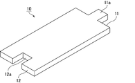
- FIG. 1 is a perspective view schematically showing an example of the mat member according to the present invention.
- FIG. 2 is a cross-sectional view schematically showing an example of the exhaust gas purifier of the present invention.
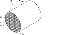
- FIG. 3A is a perspective view schematically showing an example of an exhaust gas treating body that constitutes the exhaust gas purifying apparatus of the present invention.
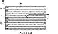
- FIG. 3B is a cross-sectional view taken along line AA of FIG. 3A. 4 is a cross-sectional photograph of a cross section parallel to the thickness direction of the mat material according to Example 1.
- FIG. 1 is a perspective view schematically showing an example of the mat member according to the present invention.
- FIG. 2 is a cross-sectional view schematically showing an example of the exhaust gas purifier of the present invention.
- FIG. 3A is a perspective view schematically showing an example of an exhaust gas treating body that constitutes the exhaust gas purifying apparatus of the present invention.
- FIG. 3B is a cross-sectional view taken along line AA of FIG. 3A
- the present invention is not limited to the following configurations, and can be appropriately modified and applied without changing the gist of the present invention.
- a combination of two or more of the individual preferred configurations of the present invention described below is also the present invention.
- FIG. 1 is a perspective view schematically showing an example of the mat member according to the present invention.
- the mat material 10 has a rectangular shape in plan view, and one end 11 of the mat material 10 has a A convex portion 11a is provided, and the other end portion 12 is provided with a concave portion 12a.
- the sealing performance is improved when the mat member 10 is arranged in an exhaust gas purifying device to be described later.
- the convex portion 11a and the concave portion 12a are formed at the center of the mat member 10 in the width direction.
- the side surface of the projection may be integrated with the side surface of the mat material. That is, when the mat member is viewed from above, the end portion may be formed in an L shape.
- the projections 11a and the recesses 12a are rectangular. There may be.
- the mat member 10 shown in FIG. 1 has the projections 11a and the recesses 12a
- the mat member of the present invention may not have the projections and recesses at the ends of the mat member.
- Such a shape includes, for example, a shape that is a parallelogram when the mat member is viewed from above.
- a parallelogram includes a rectangle.
- the mat material 10 is a mat material in which an inorganic binder and an organic binder are affixed to inorganic fibers, and the initial compression surface pressure measured by compressing the mat material 10 to a bulk density of 0.50 g/cm 3 is 900 kPa or more. . Further, the initial compression surface pressure is preferably 950 kPa or more, more preferably 1000 kPa or more. The initial compression surface pressure is preferably 1400 kPa or less, more preferably 1200 kPa or less.
- an inorganic binder is attached to inorganic fibers.
- the inorganic binder forms unevenness on the inorganic fiber surface. Such unevenness improves the coefficient of friction between inorganic fibers. As a result, the initial compression surface pressure of the mat material 10 is also improved.
- an organic binder is attached to inorganic fibers.
- the organic binder makes the inorganic fibers slippery to each other, so that when a strong stress is applied to the inorganic fibers, the inorganic fibers can be displaced and the inorganic fibers are less likely to be damaged. As a result, even when stress is continuously applied to the mat material 10, the compressive surface pressure of the mat material 10 is less likely to decrease.
- the initial compression surface pressure measured by compressing the mat member 10 to a bulk density of 0.50 g/cm 3 is 900 kPa or more, so the initial compression surface pressure is sufficiently high. Therefore, when the mat material 10 is used in an exhaust gas purifying device, which will be described later, it is possible to prevent the exhaust gas from leaking and the exhaust gas treating body from falling off from the metal casing due to the gas pressure.
- the surface pressure of the mat member 10 can be measured using, for example, a hot surface pressure measuring device manufactured by MTS, which is equipped with a heater.
- the bulk density is 0.45 g.
- the compression surface pressure of the mat material 10 compressed to 1/cm 3 is preferably 175 kPa or more, more preferably 175 to 230 kPa.
- Such a mat material 10 is suitable as a mat material for an exhaust gas purifying device, which will be described later, because the compression surface pressure of the mat material 10 is less likely to deteriorate. That is, the exhaust gas repeatedly flows into the exhaust gas purifier. Therefore, the exhaust gas treating body and the metal casing that constitute the exhaust gas purifying apparatus undergo repeated volumetric changes due to heat.
- the mat material arranged in the exhaust gas purifying device is repeatedly compressed and released.
- the mat member 10 has the above characteristics, even if compression and release are repeated, the compression surface pressure of the mat member 10 is sufficiently high. It can be well retained within the casing.
- the said 1 cycle means the following.
- the mat material is arranged between the upper plate and the lower plate of a hot contact pressure measuring device equipped with a heater.
- the upper plate is moved at a speed of 25.4 mm/min to compress the mat material to a bulk density of 0.50 g/cm 3 and then held for 10 minutes.
- the upper plate is heated to 900°C at a heating rate of 45°C/min, and the lower plate is heated to 650°C.
- the upper plate at 900° C.
- the upper plate moves the upper plate at a speed of 25.4 mm/min to release the mat material until the bulk density reaches 0.45 g/cm 3 , Hold in that state for 5 minutes.
- This compression and release are preparatory operations for conforming the mat material to the device and are not included in one cycle in the specification.
- the upper plate was moved at a speed of 25.4 mm/min to recompress the mat material until the bulk density reached 0.50 g/cm 3 . and hold for 10 minutes.
- One cycle is the step of recompressing the mat material until the bulk density reaches 0.50 g/cm 3 and the step of reopening the mat material until the bulk density reaches 0.45 g/cm 3 .
- the inorganic fibers preferably have an average fiber length of 0.1 to 10 mm, more preferably 0.2 to 8 mm. If the average fiber length of the inorganic fibers is less than 0.1 mm, the fiber length of the inorganic fibers is too short, and the shape retainability of the mat member is deteriorated. Furthermore, when the mat material is formed, the inorganic fibers are not properly entangled with each other, making it difficult to obtain a sufficient surface pressure.
- the average fiber length of the inorganic fibers exceeds 10 mm, the fiber length of the inorganic fibers is too long, and in the inorganic fiber dispersion liquid in which the inorganic fibers are dispersed in water in the papermaking process, the entanglement of the inorganic fibers becomes too strong, resulting in the formation of a mat.
- the inorganic fibers tend to accumulate unevenly, and the shear strength tends to decrease.
- the inorganic fiber length is measured by using tweezers to extract the inorganic fiber from the mat material without breaking it, and measuring the fiber length using an optical microscope.
- the average fiber length means the average length of 300 inorganic fibers extracted from the mat material and the fiber lengths measured. If the inorganic fibers cannot be removed from the mat material without breaking, the mat material is degreased, and the degreased mat material is put into water to loosen the entanglement between the inorganic fibers so that the inorganic fibers do not break. Good to take.
- the inorganic fibers preferably have an average fiber diameter of 3 to 8 ⁇ m, more preferably 5 to 7 ⁇ m. If the average fiber diameter of the inorganic fibers is less than 3 ⁇ m, the strength is low and the inorganic fibers are likely to be cut by impact or the like. When the average fiber diameter of the inorganic fibers exceeds 8 ⁇ m, the fiber diameter is too large, the Young's modulus of the inorganic fibers themselves increases, and the flexibility of the mat material tends to decrease.
- inorganic fibers examples include alumina fibers, alumina-silica fibers, silica fibers, glass wool and rock wool. Among these, alumina-silica fibers are preferred. These inorganic fibers have high heat resistance, and mat materials formed from such inorganic fibers are less likely to change shape due to temperature changes.
- alumina (Al 2 O 3 ):silica (SiO 2 ) 70:30 to 74:26.
- inorganic fibers In the mat material 10, two or more kinds of inorganic fibers may be used together.
- the type of inorganic binder is not particularly limited, but alumina sol, silica sol, airgel, fumed silica, titanium particles, and the like can be used.
- alumina sol, silica sol, airgel, fumed silica, titanium particles, and the like can be used.
- two or more kinds of inorganic binders may be used together.
- the weight ratio of the inorganic binder to the mat material 10 preferably exceeds 0 wt%, and more preferably is 0.3 wt% or more. Moreover, the weight ratio is preferably 10 wt % or less, more preferably 8 wt % or less.
- the weight ratio of the inorganic binder contained in the mat material 10 is within the above range, the irregularities formed on the surface of the inorganic fibers are sufficiently increased, and the coefficient of friction between the inorganic fibers is improved. As a result, the initial compression surface pressure of the mat material is also improved.
- the type of organic binder is not particularly limited, but rubber-based resin, styrene-based resin, silicone-based resin, acrylic-based resin, polyester-based resin, polyurethane resin, or the like can be used. In the mat material 10, two or more organic binders may be used together.
- the weight ratio of the organic binder to the mat material 10 preferably exceeds 0 wt %, and more preferably is 0.3 wt % or more. Moreover, the weight ratio is preferably 10 wt % or less, more preferably 8 wt % or less.
- the inorganic fibers are sufficiently slippery to each other, and the inorganic fibers are less likely to break. Therefore, even when stress is continuously applied to the mat material 10, the compressive surface pressure of the mat material 10 is less likely to decrease.
- the mat material 10 may contain a polymeric dispersant, a flocculant, and a surfactant in addition to the organic binder and the inorganic binder.
- the use of a polymer-based dispersant makes it easier for the inorganic binder and the organic binder to uniformly attach to the surfaces of the inorganic fibers. Become. Therefore, the effect of improving the initial compression surface pressure of the mat material 10 and the effect of preventing the compression surface pressure of the mat material 10 from decreasing even when stress is continuously applied to the mat material 10 are improved. Moreover, the mat material 10 manufactured in this manner contains a polymer-based dispersant.
- Polymeric dispersants include, but are not limited to, polycarboxylic acids and/or salts thereof, naphthalenesulfonate formalin condensates and/or salts thereof, polyacrylic acids and/or salts thereof, polymethacrylic acids and/or Hydrophilic synthetic polymeric substances such as salts thereof, polyvinyl sulfonic acid and/or salts thereof, anionic polymeric dispersants, and nonionic polymeric dispersants such as polyvinyl alcohol, polyvinylpyrrolidone, and polyethylene glycol; gelatin, natural hydrophilic macromolecular substances such as casein and water-soluble starch; and hydrophilic semi-synthetic macromolecular substances such as carboxymethylcellulose.
- hydrophilic synthetic polymeric substances are preferred, and anionic polymeric dispersants are more preferred.
- the number average molecular weight of the anionic polymeric dispersant is preferably from 500 to 100,000.
- the number average molecular weight of the anionic polymeric dispersant can be calculated, for example, from molecular weight measurement by gel permeation chromatography (GPC).
- the flocculant examples include, but are not particularly limited to, acrylamide. If a flocculant is used when manufacturing the mat material 10, the inorganic binder and the organic binder are likely to be entangled with the inorganic fibers.
- the thickness of the mat material 10 is preferably 5 to 20 mm.
- the thickness of the mat material is less than 5 mm, the surface pressure of the mat material tends to decrease.
- the exhaust gas treating body is likely to come off.
- the volume of the exhaust gas treating body changes, the mat material becomes difficult to absorb the volume change of the exhaust gas treating body. Therefore, cracks and the like are likely to occur in the exhaust gas treating body. If the thickness of the mat material exceeds 20 mm, it loses its flexibility and becomes difficult to handle. In addition, winding wrinkles and cracks are likely to occur when the mat material is wound around an exhaust gas treating body, which will be described later.
- the basis weight (weight per unit area) of the mat material 10 is not particularly limited, it is preferably 200 to 4000 g/m 2 and more preferably 900 to 3000 g/m 2 .
- the basis weight of the matting material is less than 200 g/m 2 , it becomes difficult to obtain sufficient holding power.
- the basis weight of the matting material exceeds 4000 g/m 2 , the bulk of the matting material is difficult to decrease.
- the uncompressed bulk density of the mat material 10 is preferably 0.10 to 0.30 g/cm 3 , more preferably 0.10 to 0.25 g/cm 3 . If the bulk density of the mat material is less than 0.10 g/cm 3 , the entanglement of the inorganic fibers is weak and the inorganic fibers are easily peeled off, making it difficult to maintain the desired shape of the mat material. If the bulk density of the matting material exceeds 0.30 g/cm 3 , the matting material becomes hard and easily cracks.
- the inorganic binder and the organic binder are attached to the surfaces of the inorganic fibers in a dispersed state.
- the inorganic binder and the organic binder are evenly attached to the surfaces of the inorganic fibers. Therefore, the inclusion of the inorganic binder and the organic binder has the effect of improving the initial compression surface pressure of the mat material 10, and the compression surface pressure of the mat material 10 is reduced even when stress is continuously applied to the mat material 10. Increases resistance to damage.
- aggregates composed of an inorganic binder and an organic binder may be attached to the surfaces of the inorganic fibers. Even if aggregates composed of an inorganic binder and an organic binder are affixed to the surface of inorganic fibers, the effect of improving the initial compression surface pressure of the mat material 10 and the case where stress is continuously applied to the mat material 10 However, it is possible to obtain the effect that the compression surface pressure of the mat member 10 is less likely to decrease.
- the mat material 10 whether the inorganic binder and the organic binder are attached to the surfaces of the inorganic fibers in a dispersed state, or whether aggregates composed of the inorganic binder and the organic binder are attached to the surfaces of the inorganic fibers depends on the mat material. It can be determined by taking out the inorganic fiber from 10 and observing the surface of the inorganic fiber using a scanning electron microscope (SEM).
- SEM scanning electron microscope
- the mat material 10 may be a paper-made mat or a needle mat, but is preferably a paper-made mat.
- the mat material 10 is manufactured by papering inorganic fibers, so that the inorganic fibers are less likely to be damaged during manufacturing. Therefore, the initial compression surface pressure of the mat material 10 can be easily improved.
- the inorganic binder and the organic binder can be attached to the obtained inorganic fibers only by adding the inorganic binder and the organic binder to the inorganic fiber dispersion liquid used for papermaking.
- the mat material 10 when the mat material 10 is a paper-made mat, the mat material 10 includes an inorganic fiber dispersion in which the inorganic fibers contained in the inorganic fiber dispersion have a bulk specific gravity in water of 0.001 to 0.02 g/cm 3 , It is preferable to form an inorganic fiber-binder mixed liquid in which an inorganic binder and an organic binder are mixed into paper.
- the bulk specific gravity of the inorganic fibers in water is more preferably 0.002 to 0.01 g/cm 3 .
- the reason why the surface pressure is generated in the mat member 10 is that friction is generated at the contact points between the inorganic fibers, and a force that inhibits the movement of the inorganic fibers is generated.
- the surface pressure of the mat material 10 is improved.
- the inorganic fibers that form the twisted twist will be bundled, so the twisted twist can be regarded as one inorganic fiber. Therefore, the number of inorganic fibers in the mat material 10 is reduced. Moreover, the specific surface area of the entire inorganic fibers contained in the mat member 10 is reduced.
- the number of contact points between the inorganic fibers in the mat material 10 is reduced, and the initial compression surface pressure of the mat material 10 tends to be low.
- an inorganic fiber dispersion having a bulk specific gravity in water of 0.001 to 0.02 g/cm 3 the existence ratio of grains in which inorganic fibers are twisted together is low. Further, even in the mat member 10 manufactured using such an inorganic fiber dispersion, the existence ratio of shavings is low. Therefore, the number of contact points between the inorganic fibers in the mat material 10 can be sufficiently increased, and as a result, the initial compression surface pressure of the mat material 10 is also improved.
- the inorganic fibers are uniformly dispersed, so stress can be easily dispersed. Therefore, even when stress is continuously applied to the mat member 10, the inorganic fibers are less likely to be damaged. As a result, even when stress is continuously applied to the mat material 10, the compressive surface pressure of the mat material 10 is less likely to decrease.
- the water bulk specific gravity of the inorganic fibers of the mat material means a value measured by the following method.
- the mat material is heat-treated at 600° C. for 1 hour to burn off the organic component.
- 0.5 g of the mat material after the heat treatment is collected while manually loosening the inorganic fibers.
- the collected inorganic fibers are placed in a container containing 80 mL of water, and stirred at 1000 rpm for 10 minutes.
- the aqueous solution containing inorganic fibers is transferred to a 100 mL graduated cylinder, and water is added until the lower surface of the meniscus of the aqueous solution is positioned at the 100 mL scale.
- the sedimentation height of the inorganic fibers was read, the product of the sedimentation height of the inorganic fibers and the area of the bottom surface of the graduated cylinder was taken as the volume of the inorganic fibers in water, and the weight of the inorganic fibers (0.5 g) was taken as the inorganic fibers.
- the value obtained by dividing by the volume in water is taken as the underwater bulk specific gravity of the inorganic fiber of the mat material.
- the mat material 10 is preferably formed by papermaking from an inorganic fiber-binder mixed liquid obtained by mixing an inorganic fiber dispersion containing a surfactant, an inorganic binder, and an organic binder.
- an inorganic fiber dispersion liquid obtained by mixing an inorganic fiber dispersion containing a surfactant, an inorganic binder, and an organic binder.
- the proportion of the grains in the obtained mat material 10 is reduced, and the initial compression surface pressure of the mat member 10 is improved. Further, even when stress is continuously applied to the mat material 10, the compressive surface pressure of the mat material 10 is less likely to decrease.
- the type of surfactant is not particularly limited, but polycarboxylic acid-based surfactants, acrylic acid-based surfactants, and the like can be mentioned. Among these, polycarboxylic acid-based surfactants are preferred.
- the polycarboxylic acid-based surfactant can increase the negative charge on the surface of the fiber, and the inorganic fibers repel each other, making it more difficult for the inorganic fibers to twist.
- the mat material 10 When the mat material 10 is a paper-made mat, the mat material 10 includes grains made of twisted inorganic fibers. is preferably 0.5% or more, more preferably 0.7% or more. Moreover, the area ratio of the cross section of the koyori is preferably 10% or less, more preferably 9% or less. When the ratio of the area of the cross section of the grain to the area of the cross section of the mat material 10 is within the above range, the existence ratio of the grain is appropriate, so that the initial compression surface pressure of the mat member 10 is improved.
- An exhaust gas purifier using the mat material 10 is also one aspect of the present invention.
- FIG. 2 is a cross-sectional view schematically showing an example of the exhaust gas purifier of the present invention.
- the exhaust gas purification apparatus 1 includes an exhaust gas treating body 20, a metal casing 30 that houses the exhaust gas treating body 20, and a mat material 10 that is arranged between the exhaust gas treating body 20 and the metal casing 30. consists of In the exhaust gas purifier 1, the mat material 10 functions as a holding seal material.
- the exhaust gas purifier 1 has a mat material 10 . Since the initial compression surface pressure of the mat material 10 is sufficiently high, it is possible to prevent the exhaust gas from leaking and the exhaust gas treating body 20 from falling off from the metal casing 30 due to gas pressure.
- FIG. 3A is a perspective view schematically showing an example of an exhaust gas treating body that constitutes the exhaust gas purifying apparatus of the present invention.
- FIG. 3B is a cross-sectional view taken along line AA of FIG. 3A.
- the exhaust gas treating body 20 included in the exhaust gas purifier 1 has a columnar shape in which a large number of cells 21 are arranged in parallel in the longitudinal direction with cell walls 22 interposed therebetween.
- the exhaust gas treating body 20 is an exhaust gas filter (honeycomb filter) in which one of the cells 21 is plugged with a plugging material 23 .
- the exhaust gas discharged from the internal combustion engine and flowing into the exhaust gas treating body 20 (in FIG. 3B, the exhaust gas is indicated by G and the flow of the exhaust gas is indicated by an arrow) is It flows into one cell 21 that is open to the outside and passes through the cell wall 22 that separates the cells 21 .
- the PM in the exhaust gas is captured by the cell walls 22, and the exhaust gas is purified.
- the purified exhaust gas flows out from another cell 21 opened at the exhaust gas outflow side end surface and is discharged to the outside.
- the exhaust gas treating body 20 shown in FIGS. 3A and 3B is a filter in which one end of the cell 21 is sealed with a sealing material 23, but the exhaust gas constituting the exhaust gas purifying apparatus of the present invention
- the processing body does not have to be sealed at the ends of the cells.
- Such an exhaust gas treating body can be suitably used as a catalyst carrier.
- the exhaust gas treating body 20 may be made of a non-oxidized porous ceramic such as silicon carbide or silicon nitride, or may be made of an oxidized porous ceramic such as sialon, alumina, corderite, or mullite. Among these, silicon carbide is preferred.
- the porosity of the porous ceramic is not particularly limited, but is preferably 35 to 60%. If the porosity is less than 35%, the exhaust gas treating body may quickly become clogged.
- the average pore diameter of the porous ceramic is preferably 5 to 30 ⁇ m. If the average pore size is less than 5 ⁇ m, PM may easily cause clogging. If the average pore size exceeds 30 ⁇ m, PM passes through the pores, and the filter may not be able to collect PM and fail to function as a filter.
- the porosity and pore diameter can be measured by a conventionally known method of measurement using a scanning electron microscope (SEM).
- the cell density in the cross section of the exhaust gas treating body 20 is not particularly limited, but the preferable lower limit is 31.0 cells/cm 2 (200 cells/inch 2 ), and the preferable upper limit is 93.0 cells/cm 2 (600 cells/inch 2 ). inch 2 ). A more preferable lower limit is 38.8/cm 2 (250/inch 2 ), and a more preferable upper limit is 77.5/cm 2 (500/inch 2 ).
- the exhaust gas treating body 20 may carry a catalyst for purifying the exhaust gas, and the catalyst to be carried is preferably a noble metal such as platinum, palladium, rhodium, etc. Among them, platinum is more preferable.
- a noble metal such as platinum, palladium, rhodium, etc.
- platinum is more preferable.
- alkali metals such as potassium and sodium, and alkaline earth metals such as barium can also be used. These catalysts may be used alone or in combination of two or more. When these catalysts are carried, it becomes easier to burn and remove PM, and it becomes possible to purify toxic exhaust gas.
- Metal casing 30 is generally cylindrical. It is preferable that the inner diameter of the metal casing 30 (the inner diameter of the portion accommodating the exhaust gas treating body) be slightly shorter than the diameter of the exhaust gas treating body 20 around which the mat material 10 is wound.
- the inner diameter of the metal casing 30 is such a length, the mat material 10 is compressed after the exhaust gas treating body 20 wrapped with the mat material 10 is press-fitted into the metal casing 30 , so that the mat material 10 is subjected to surface pressure. occurs.
- the initial compression surface pressure of the mat material 10 is sufficiently high, it is possible to prevent the exhaust gas from leaking and the exhaust gas treating body 20 from falling off from the metal casing 30 due to the gas pressure.
- the metal casing 30 is not particularly limited, it is preferably made of stainless steel.
- the method for producing a mat material of the present invention includes a defibration step of adding water to pre-fibrillation inorganic fibers to fibrillate the pre-fibrillation inorganic fibers to prepare an inorganic fiber dispersion, an inorganic fiber dispersion, an inorganic A step of preparing an inorganic fiber-binder mixed solution by mixing a binder and an organic binder to form an inorganic fiber-binder mixed solution, a papermaking step of making a mat precursor by making and dehydrating the inorganic fiber-binder mixed solution, and a mat precursor and a heating and pressurizing step of heating and pressurizing the body to form a mat material.
- a defibration step of adding water to pre-fibrillation inorganic fibers to fibrillate the pre-fibrillation inorganic fibers to prepare an inorganic fiber dispersion, an inorganic fiber dispersion, an inorganic
- the inorganic fibers before defibration may be produced by a conventionally known method, or may be commercially available.
- methods for producing pre-disentanglement inorganic fibers include the following methods. That is, a spinning mixture containing basic aluminum chloride and silica sol is spun by a blowing method to produce an inorganic fiber precursor. Next, the inorganic fiber precursor is compressed to produce a rectangular sheet, and the compressed sheet is calcined to produce inorganic fibers before disentanglement composed of silica-alumina fibers.
- the defibration method is not particularly limited, but the inorganic fibers before defibration may be dry defibrated and then wet defibrated by adding water, or may be wet defibrated by adding water from the beginning. .
- Defibrillation can be performed using machines such as slush pulpers, feather mills, disc mills, bale openers, beaters, hammer mills, carders, and wool vickers. Defibrillation may be performed using one type of machine, or may be performed using two or more types of machines.
- Examples of wet fibrillation methods using a slush pulper include the following methods. 1,000 L of water is added to 10 kg of the inorganic fibers before disentanglement, and the mixture is stirred with a slush pulper at 2,000 to 5,000 rpm for 5 to 60 minutes to crush the inorganic fibers before disentanglement into short fibers. A method of defibrating is mentioned.
- the disentanglement step it is preferable to further add a surfactant to the pre-disentanglement inorganic fibers to disentangle the pre-disentanglement inorganic fibers.
- a surfactant during defibration of the pre-fibrillation inorganic fibers can reduce entanglement of the inorganic fibers.
- the existence ratio of grains in which the inorganic fibers are twisted together becomes low.
- a mat material having a sufficiently high initial compression surface pressure is produced by performing an inorganic fiber-binder mixed solution preparation step, a papermaking step, and a heating and pressurizing step. can do.
- the mat material manufactured in this way is less likely to have its compressive surface pressure lowered even when stress is continuously applied.
- the type of surfactant used in the fibrillation step is not particularly limited, but examples thereof include polycarboxylic acid-based surfactants and acrylic acid-based surfactants.
- the amount of surfactant used in the fibrillation step is not particularly limited, but it is preferably 0.1 to 10 g per 1 L of water.
- the inorganic fibers before defibration are preferably defibrated so that the bulk specific gravity of the inorganic fibers after defibration in water is 0.001 to 0.02 g/cm 3 , and preferably 0.002 to 0.02 g/cm 3 . It is more preferable to defibrate the pre-fibrillation inorganic fibers so as to have a density of 01 g/cm 3 .
- the proportion of iron shavings contained in the produced matting material is also reduced. Therefore, the number of contact points between the inorganic fibers in the mat material can be sufficiently increased, and as a result, the initial compression surface pressure of the mat material is also improved.
- the inorganic fibers are uniformly dispersed, so stress can be easily dispersed. Therefore, even when stress is continuously applied to the manufactured mat material, the inorganic fibers are less likely to be damaged. As a result, even when stress is continuously applied to the manufactured mat material, the compressive surface pressure of the mat material is less likely to decrease.
- the underwater bulk specific gravity of the inorganic fiber after fibrillation means the value measured by the following method.
- the defibrated inorganic fibers are dried by heat treatment under the condition of 600° C. for 1 hour.
- 0.5 g of the inorganic fiber after heat treatment is sampled.
- the collected inorganic fibers are placed in a container containing 80 mL of water, and stirred at 1000 rpm for 10 minutes.
- the aqueous solution containing inorganic fibers is transferred to a 100 mL graduated cylinder, and water is added until the lower surface of the meniscus of the aqueous solution is positioned at the 100 mL scale.
- the sedimentation height of the inorganic fibers was read, the product of the sedimentation height of the inorganic fibers and the area of the bottom surface of the graduated cylinder was taken as the volume of the inorganic fibers in water, and the weight of the inorganic fibers (0.5 g) was taken as the inorganic fibers.
- the value obtained by dividing by the volume in water is taken as the bulk specific gravity in water of the inorganic fiber after fibrillation.
- Inorganic fiber-binder mixture preparation process In the inorganic fiber-binder mixture preparation step, the inorganic fiber dispersion prepared in the fibrillation step, the inorganic binder and the organic binder are mixed to obtain an inorganic fiber-binder mixture.
- the type of inorganic binder is not particularly limited, alumina sol, silica sol, aerogel, fumed silica, titanium particles, and the like can be used.
- the weight of the inorganic binder to be added is preferably more than 0 wt %, more preferably 0.3 wt % or more, relative to the weight of the inorganic fibers contained in the inorganic fiber dispersion.
- the weight ratio is preferably 10 wt % or less, more preferably 8 wt % or less.
- the type of organic binder is not particularly limited, but rubber-based resins, styrene-based resins, silicone-based resins, acrylic-based resins, polyester-based resins, polyurethane resins, and the like can be used.
- the weight of the organic binder to be added is preferably more than 0 wt %, more preferably 0.3 wt % or more, relative to the weight of the inorganic fibers contained in the inorganic fiber dispersion.
- the weight ratio is preferably 10 wt % or less, more preferably 8 wt % or less.
- a polymeric dispersant may be further added to the inorganic fiber dispersion.
- the inorganic binder and the organic binder are more likely to adhere uniformly to the surfaces of the inorganic fibers. Therefore, the initial compressive surface pressure of the mat material obtained through the process described later is likely to be improved, and even when stress is continuously applied to the mat material, the compressive surface pressure of the mat material is less likely to decrease.
- Polymeric dispersants include, but are not limited to, polycarboxylic acids and/or salts thereof, naphthalenesulfonate formalin condensates and/or salts thereof, polyacrylic acids and/or salts thereof, polymethacrylic acids and/or Anionic polymeric dispersants such as salts thereof, polyvinyl sulfonic acid and/or salts thereof, hydrophilic synthetic polymeric substances such as nonionic polymeric dispersants such as polyvinyl alcohol, polyvinylpyrrolidone and polyethylene glycol; gelatin; , casein, and water-soluble starch; and hydrophilic semi-synthetic high-molecular substances such as carboxymethyl cellulose. Among these, hydrophilic synthetic polymeric substances are preferred, and anionic polymeric dispersants are more preferred.
- the number average molecular weight of the anionic polymeric dispersant is preferably from 500 to 100,000.
- flocculant examples include, but are not particularly limited to, acrylamide.
- acrylamide acrylamide
- the inorganic fiber-binder mixed solution prepared in the inorganic fiber-binder mixed solution preparation step is made into paper and dehydrated to obtain a mat precursor.
- the method and conditions for papermaking and dehydration are not particularly limited. Conventionally known methods and conditions can be employed. For example, it is preferable to make paper using a continuous paper making machine so that the basis weight of the mat material after production is 1000 to 3000 g/m 2 .
- heating and pressurizing step In the heating and pressurizing step, the mat precursor produced in the papermaking step is heated and pressurized to form a mat member.
- the heating and pressurizing conditions are preferably 100 to 300° C. for 5 to 15 minutes.
- the mat member of the present invention can be manufactured through the above steps.
- the obtained mat material can be cut into a desired size as necessary.
- an organic polymer polyvinyl alcohol
- the weight of the inorganic binder is set to 2 wt% with respect to the weight of the inorganic fibers contained in the inorganic fiber dispersion, and the weight of the organic binder is set to 7 wt% of the weight of the inorganic fibers contained in the inorganic fiber dispersion.
- the weight of the polymeric dispersant was adjusted to 1 wt % with respect to the weight of the inorganic fibers contained in the inorganic fiber dispersion.
- the mat member according to Example 1 was manufactured by cutting the mat member into a length of 300 cm and a width of 100 cm.
- the initial compression surface pressure measured by compressing the mat material according to Example 1 to a bulk density of 0.50 g/cm 3 was 902 kPa.
- FIG. 4 shows a cross-sectional photograph of the cross section of the mat member according to Example 1. As shown in FIG. 4 is a cross-sectional photograph of a cross section parallel to the thickness direction of the mat material according to Example 1.
- FIG. 4 it was observed that the mat material according to Example 1 contained coyori (indicated by arrows in FIG. 4) in which inorganic fibers were twisted together.
- the ratio of the cross-sectional area of the koyori to the cross-sectional area of the mat material was measured and found to be 0.5%.
- Comparative example 1 A mat material according to Comparative Example 1 was manufactured in the same manner as in Example 1, except that the inorganic binder was not added in the inorganic fiber-binder mixture preparation step.
- the initial compression surface pressure measured by compressing the mat material according to Comparative Example 1 to a bulk density of 0.50 g/cm 3 was 812 kPa.
- Comparative example 2 A mat material according to Comparative Example 1 was produced in the same manner as in Example 1, except that the organic binder was not added in the inorganic fiber-binder mixture preparation step.
- the initial compression surface pressure measured by compressing the mat material according to Comparative Example 2 to a bulk density of 0.50 g/cm 3 was 885 kPa.
- Each mat member was placed between the upper plate and the lower plate of a hot contact pressure measuring device manufactured by MTS, which was equipped with a heater.
- the upper plate was moved at a speed of 25.4 mm/min to compress the mat material to a bulk density of 0.50 g/cm 3 and then held for 10 minutes.
- the upper plate was heated to 900°C at a heating rate of 45°C/min, and the lower plate was heated to 650°C.
- the upper plate at 900° C. and the lower plate at 650° C., move the upper plate at a speed of 25.4 mm/min to release the mat material until the bulk density reaches 0.45 g/cm 3 , This state was maintained for 5 minutes.
- the upper plate was moved at a speed of 25.4 mm/min to recompress the mat material until the bulk density reached 0.50 g/cm 3 . and held for 10 minutes.
- the upper plate was moved at a speed of 25.4 mm/min to re-release the mat material until the bulk density reaches 0.45 g/ cm3 . and held for 10 minutes.
- the step of recompressing the mat material until the bulk density reaches 0.50 g/cm 3 and the step of reopening the mat material until the bulk density reaches 0.45 g/cm 3 are repeated for 1000 cycles, and after 1000 cycles, The compression surface pressure of each mat material compressed to a bulk density of 0.45 g/cm 3 was measured. Table 1 shows the results.
- the initial compression surface pressure of the mat material is sufficiently high, and the compression surface pressure after repeated compression and release is also sufficiently high. found.
- Exhaust gas purifying device 10 Mat material 11 One end 11a Protruding portion 12 The other end 12a Recessed portion 20 Exhaust gas treating body 21 Cell 22 Cell wall 23 Sealing material 30 Metal casing
Landscapes
- Engineering & Computer Science (AREA)
- Chemical & Material Sciences (AREA)
- Chemical Kinetics & Catalysis (AREA)
- Health & Medical Sciences (AREA)
- Environmental & Geological Engineering (AREA)
- Textile Engineering (AREA)
- General Chemical & Material Sciences (AREA)
- General Engineering & Computer Science (AREA)
- Biomedical Technology (AREA)
- Oil, Petroleum & Natural Gas (AREA)
- Analytical Chemistry (AREA)
- Mechanical Engineering (AREA)
- Toxicology (AREA)
- Combustion & Propulsion (AREA)
- Ceramic Engineering (AREA)
- Inorganic Chemistry (AREA)
- Dispersion Chemistry (AREA)
- Materials Engineering (AREA)
- Organic Chemistry (AREA)
- Structural Engineering (AREA)
- Paper (AREA)
- Exhaust Gas After Treatment (AREA)
- Porous Artificial Stone Or Porous Ceramic Products (AREA)
Abstract
Description
また、特許文献1には、当該シール材を製造する方法として、無機短繊維を媒体に分散させてスラリーを調製し、それを抄造法で所望形状にシート成形した後乾燥し、必要に応じて裁断する際に、有機質バインダーをスラリーに存在させるか、シート成形した後に添加するか、又はその両方であり、しかも乾燥は圧縮力を付与しながら行うことを特徴とするシール材の製造方法が開示されている。
そのため、本発明のマット材を排ガス浄化装置に用いた場合、排ガスの漏れや、ガス圧により排ガス処理体が金属ケーシングから脱落することを防ぐことができる。
本発明のマット材に含まれる無機バインダの重量割合が上記範囲である場合、無機繊維の表面に形成される凹凸が充分に多くなり、無機繊維同士の摩擦係数が向上する。その結果、マット材の初期圧縮面圧も向上する。
本発明のマット材に含まれる有機バインダの重量割合が上記範囲である場合、無機繊維同士が充分に滑りやすくなり、無機繊維が破損されにくくなる。そのため、マット材に連続的に応力がかかった場合でもマット材の圧縮面圧が低下しにくくなる。
無機バインダ及び有機バインダが、それぞれ分散した状態で無機繊維の表面に添着されていると、無機繊維の表面に斑なく無機バインダ及び有機バインダが添着されることになる。そのため、無機バインダ及び有機バインダを含むことによる、マット材の初期圧縮面圧が向上する効果、及び、マット材に連続的に応力がかかった場合でもマット材の圧縮面圧が低下しにくくなる効果が向上する。
本発明のマット材を製造する場合において、無機バインダ及び有機バインダを無機繊維の表面に添着させる際に、高分子系分散剤を用いると、無機バインダ及び有機バインダが、均一に無機繊維表面に添着しやすくなる。
無機繊維の表面に、無機バインダ及び有機バインダからなる凝集体が添着されていたとしても、マット材の初期圧縮面圧が向上する効果、及び、マット材に連続的に応力がかかった場合でもマット材の圧縮面圧が低下しにくくなる効果を得ることができる。
抄造マットは、無機繊維を抄いて製造されるので、製造中に無機繊維が損傷しにくい。そのため、マット材の初期圧縮面圧を向上しやすくなる。
マット材に面圧が生じる理由は、無機繊維同士の接点において摩擦が生じ、無機繊維が動くことを阻害する力が生じるためである。マット材において、無機繊維同士の接点の数が多いと、摩擦が発生する箇所が多くなるので、マット材の面圧は向上する。
マット材に、無機繊維同士が縒れたコヨリが存在すると、コヨリを形成する無機繊維が束になってしまうので、コヨリを一つの無機繊維とみなせる。そのため、マット材における無機繊維の数が減少することになる。また、マット材に含まれる無機繊維全体の比表面積が小さくなる。そうすると、マット材における無機繊維同士の接点の数が少なくなり、マット材の初期圧縮面圧が低くなる傾向がある。
水中嵩比重が、0.001~0.02g/cm3である無機繊維分散液では、無機繊維同士が縒れたコヨリの存在割合が低くなる。また、このような無機繊維分散液を用いて製造されたマット材でもコヨリの存在割合は低くなる。そのため、マット材における無機繊維同士の接点の数を充分に多くすることができ、その結果、マット材の初期圧縮面圧も向上する。
また、このような無機繊維分散液を用いて製造されたマット材では、無機繊維が均一に分散するので、応力を分散しやすくなる。そのため、マット材に連続的に応力がかかった場合でも、無機繊維が破損されにくくなる。その結果、マット材に連続的に応力がかかった場合でもマット材の圧縮面圧が低下しにくくなる。
マット材の断面の面積に対するコヨリの断面の面積の割合が上記範囲であると、コヨリの存在割合が適度な割合となるので、マット材の初期圧縮面圧が向上する。
このようなマット材は、圧縮面圧が劣化しにくいので、排ガス浄化装置用のマット材として適している。
解繊後の無機繊維の水中嵩比重を上記範囲とすることで、無機繊維分散液におけるコヨリの存在割合を低くすることができる。
以下、本発明のマット材について説明する。
しかしながら、本発明は、以下の構成に限定されるものではなく、本発明の要旨を変更しない範囲において適宜変更して適用することができる。なお、以下において記載する本発明の個々の好ましい構成を2つ以上組み合わせたものもまた本発明である。
図1は、本発明に係るマット材の一例を模式的に示す斜視図である。
図1に示すように、マット材10は、平面視矩形であり、マット材10を対象物に巻き付ける際に、端部同士が嵌合するように、マット材10の一方の端部11には凸部11aが設けられており、もう一方の端部12に凹部12aが設けられている。
このような凸部11a及び凹部12aが設けられていると、マット材10を後述する排ガス浄化装置に配置した際に、シール性が向上する。
なお、図1に示すマット材10では、凸部11a及び凹部12aは、マット材10の短手方向の中心に形成されているが、本発明のマット材では、凸部及び凹部は、互いに勘合できればマット材の短手方向の中心に形成されていなくてもよい。例えば、凸部の側面が、マット材の側面と一体化していてもよい。すなわち、マット材を平面視した際に、端部がL字状に形成されていてもよい。
また、図1に示すマット材10では、凸部11a及び凹部12aは矩形であるが、本発明のマット材では、凸部及び凹部は、互いに勘合できれば、三角形や半円形等の別の形状であってもよい。
また、図1に示すマット材10では、凸部11a及び凹部12aが形成されていたが、本発明のマット材は、マット材の端部に凸部及び凹部を有していなくてもよい。
このような形状としては、例えば、マット材を平面視した際に平行四辺形である形状が挙げられる。なお、平行四辺形は矩形を含む。マット材がこのような形状である場合、マット材を対象物に巻き付けた際に、一方の端部ともう一方の端部を丁度接触させることができる。また、マット材の一方の端部ともう一方の端部は直線状に形成されている必要は無く、例えば、一方の端部ともう一方の端部とが丁度接触するようなギザギザが形成されていてもよい。
また、上記初期圧縮面圧は、950kPa以上であることが好ましく、1000kPa以上であることがより好ましい。また、上記初期圧縮面圧は、1400kPa以下であることが好ましく、1200kPa以下であることがより好ましい。
そのため、マット材10を後述する排ガス浄化装置に用いた場合、排ガスの漏れや、ガス圧により排ガス処理体が金属ケーシングから脱落することを防ぐことができる。
このようなマット材10は、圧縮面圧が劣化しにくいので、後述する排ガス浄化装置用のマット材として適している。
つまり、排ガス浄化装置では、排ガスが繰り返し流入する。そのため、排ガス浄化装置を構成する排ガス処理体及び金属ケーシングは、熱により繰り返し体積変化することになる。
排ガス処理体や金属ケーシングの体積変化に伴い、排ガス浄化装置に配置されたマット材は、圧縮及び開放が繰り返される。
マット材10が上記特徴を有する場合、圧縮及び解放が繰り返し行われたとしてもマット材10の圧縮面圧が充分に高いので、排ガス浄化装置に排ガスが繰り返し流入したとしても、排ガス処理体を金属ケーシング内に充分に保持することができる。
まず、マット材を加熱ヒーターを備えた熱間面圧測定装置の上部板と、下部板との間に配置する。
次に、室温において、上部板を25.4mm/minの速度で動かして、嵩密度が0.50g/cm3となるまでマット材を圧縮した後、10分間保持する。
その後、マット材を圧縮した状態で、45℃/mimの昇温速度で上部板を900℃まで昇温し、下部板を650℃まで加熱する。
次に、上部板を900℃とし、下部板を650℃としたまま、上部板を25.4mm/minの速度で動かして嵩密度が0.45g/cm3となるまでマット材を開放し、その状態で5分間保持する。この圧縮及び開放は、マット材を装置になじませるための準備操作であり、明細書における1サイクルに含めない。
次に、上部板を900℃とし、下部板を650℃としたまま、上部板を25.4mm/minの速度で動かして、嵩密度が0.50g/cm3となるまでマット材を再圧縮し、10分間保持する。
次に、上部板を900℃とし、下部板を650℃としたまま、上部板を25.4mm/minの速度で動かして、嵩密度が0.45g/cm3となるまでマット材を再解放し、10分間保持する。
嵩密度が0.50g/cm3となるまでマット材を再圧縮する工程、及び、嵩密度が0.45g/cm3となるまでマット材を再開放する工程が1サイクルである。
無機繊維の平均繊維長が0.1mm未満であると、無機繊維の繊維長が短すぎるため、マット材としての形状保持性が低下してしまう。さらに、マット材にしたときに無機繊維同士に好適な絡み合いが起こらず、充分な面圧を得ることが困難になる。
無機繊維の平均繊維長が10mmを超えると、無機繊維の繊維長が長すぎるため、抄造工程で水に無機繊維を分散した無機繊維分散液において、無機繊維同士の絡み合いが強くなりすぎるため、マット材としたときに無機繊維が不均一に集積しやすくなり、せん断強度も低下しやすくなる。
本明細書において、平均繊維長とは、マット材から無機繊維300本を抜き取り、繊維長を計測した平均長さを意味する。マット材から無機繊維を破断せずに抜き取れない場合、マット材を脱脂処理して、脱脂済みマット材を水の中へ投入し、無機繊維同士の絡みをほぐしながら無機繊維が破断しないように採取すると良い。
無機繊維の平均繊維径が3μm未満であると、強度が弱く、衝撃等により無機繊維が裁断されやすくなる。
無機繊維の平均繊維径が8μmを超えると、繊維径が太すぎ無機繊維自体のヤング率が高くなりマット材の柔軟性が低くなりやすくなる。
これらの無機繊維は耐熱性が高く、このような無機繊維により形成されたマット材は、温度変化によって形状変化しにくい。
マット材10では、無機バインダが2種以上併用されていてもよい。
マット材10に含まれる無機バインダの重量割合が上記範囲である場合、無機繊維の表面に形成される凹凸が充分に多くなり、無機繊維同士の摩擦係数が向上する。その結果、マット材の初期圧縮面圧も向上する。
マット材10では、有機バインダが2種以上併用されていてもよい。
マット材10に含まれる有機バインダの重量割合が上記範囲である場合、無機繊維同士が充分に滑りやすくなり、無機繊維が破損されにくくなる。そのため、マット材10に連続的に応力がかかった場合でもマット材10の圧縮面圧が低下しにくくなる。
また、このように製造されたマット材10は、高分子系分散剤を含むことになる。
これらの中では、親水性合成高分子物質が好ましく、アニオン性高分子系分散剤がより好ましい。アニオン性高分子系分散剤の数平均分子量は500~100000であることが好ましい。アニオン性高分子系分散剤の数平均分子量は、例えば、ゲル浸透クロマトグラフィ(GPC)による分子量測定から算出することができる。
マット材10を製造する場合において凝集剤を用いると、無機バインダ及び有機バインダが無機繊維に絡みつきやすくなる。
マット材の厚さが5mm未満であると、マット材の面圧が低下しやすくなる。また、マット材を後述する排ガス浄化装置に用いた際に、排ガス処理体が抜け落ちやすくなる。また、排ガス処理体に体積変化が生じた場合、マット材は排ガス処理体の体積変化を吸収しにくくなる。そのため、排ガス処理体にクラック等が発生しやすくなる。
マット材の厚みが20mmを超えると、柔軟性が失われるので扱いづらくなる。また、マット材を後述する排ガス処理体に巻き付けた際に、巻きジワや割れが生じやすくなる。
マット材の目付量が200g/m2未満であると、保持力が充分になりにくくなる。
マット材の目付量が4000g/m2を超えると、マット材の嵩が低くなりにくい。
マット材の嵩密度が0.10g/cm3未満であると、無機繊維のからみ合いが弱く、無機繊維が剥離しやすいため、マット材の形状を所定の形状に保ちにくくなる。
マット材の嵩密度が0.30g/cm3を超えると、マット材が硬くなるためマット材が割れやすくなる。
無機バインダ及び有機バインダが、それぞれ分散した状態で無機繊維の表面に添着されていると、無機繊維の表面に斑なく無機バインダ及び有機バインダが添着されることになる。そのため、無機バインダ及び有機バインダを含むことによる、マット材10の初期圧縮面圧が向上する効果、及び、マット材10に連続的に応力がかかった場合でもマット材10の圧縮面圧が低下しにくくなる効果が向上する。
無機繊維の表面に、無機バインダ及び有機バインダからなる凝集体が添着されていたとしても、マット材10の初期圧縮面圧が向上する効果、及び、マット材10に連続的に応力がかかった場合でもマット材10の圧縮面圧が低下しにくくなる効果を得ることができる。
マット材10が抄造マットである場合、マット材10は、無機繊維を抄いて製造されるので、製造中に無機繊維が損傷しにくい。そのため、マット材10の初期圧縮面圧を向上しやすくなる。
また、抄造を行う際に用いる無機繊維分散液に無機バインダ及び有機バインダを加えるだけで、得られる無機繊維に無機バインダ及び有機バインダを添着することができる。
マット材10に、無機繊維同士が縒れたコヨリが存在すると、コヨリを形成する無機繊維が束になってしまうので、コヨリを一つの無機繊維とみなせる。そのため、マット材10における無機繊維の数が減少することになる。また、マット材10に含まれる無機繊維全体の比表面積が小さくなる。そうすると、マット材10における無機繊維同士の接点の数が少なくなり、マット材10の初期圧縮面圧が低くなる傾向がある。
水中嵩比重が、0.001~0.02g/cm3である無機繊維分散液では、無機繊維同士が縒れたコヨリの存在割合が低くなる。また、このような無機繊維分散液を用いて製造されたマット材10でもコヨリの存在割合は低くなる。そのため、マット材10における無機繊維同士の接点の数を充分に多くすることができ、その結果、マット材10の初期圧縮面圧も向上する。
また、このような無機繊維分散液を用いて製造されたマット材10では、無機繊維が均一に分散するので、応力を分散しやすくなる。そのため、マット材10に連続的に応力がかかった場合でも、無機繊維が破損されにくくなる。その結果、マット材10に連続的に応力がかかった場合でもマット材10の圧縮面圧が低下しにくくなる。
まず、マット材を600℃で1時間の条件で熱処理を行い有機成分を焼失させる。
次に、熱処理後のマット材から無機繊維を手で解しながら0.5gを採取する。その後、採取した無機繊維を80mLの水の入った容器に入れ、1000rmp、10分間の条件で攪拌処理を行う。
次に、無機繊維を含む水溶液を100mLメスシリンダーに移し変え、さらに、当該水溶液のメニスカスの下面が100mLの目盛に位置するまで水を加える。
30分間静置後、無機繊維の沈降高さを読み取り、無機繊維の沈降高さとメスシリンダーの底面の面積との積を無機繊維の水中体積とし、無機繊維の重量(0.5g)を無機繊維の水中体積で除した値をマット材の無機繊維の水中嵩比重とする。
無機繊維分散液を作製する場合、解繊前無機繊維に水を加え、解繊前無機繊維を破砕し短繊維化することにより解繊する。この際、界面活性剤の存在下で解繊を行うと、得られる無機繊維同士が縒れにくくなりコヨリが生じにくい。
コヨリが少ない無機繊維分散液を用いて、マット材10を抄造すると、得られたマット材10でもコヨリの存在割合が低くなり、マット材10の初期圧縮面圧が向上する。また、マット材10に連続的に応力がかかった場合でもマット材10の圧縮面圧が低下しにくくなる。
これらの中では、ポリカルボン酸系界面活性剤が好ましい。ポリカルボン酸系界面活性剤は、繊維表面の負電荷を増大させることができ、無機繊維同士が反発するので、無機繊維同士がさらに縒れにくくなる。
マット材10の断面の面積に対するコヨリの断面の面積の割合が上記範囲であると、コヨリの存在割合が適度な割合となるので、マット材10の初期圧縮面圧が向上する。
まず、マット材を厚さ方向に平行に切断し、切断面をスキャンする。次に、断面の任意の位置における縦×横=50×50mmの範囲を選択し、その範囲を画像データとして取得する。
得られた画像データを二値化し、コヨリの断面部分とそうでない断面を識別可能な状態とする。
次に、コヨリの断面の面積を算出し、その画像におけるコヨリの断面の面積の割合を算出する。
マット材の断面における選択する範囲を変更する以外は同様の操作を3回繰り返し、各画像におけるコヨリの断面の面積の割合の平均値をマット材の断面の面積に対するコヨリの断面の面積の割合とする。
なお、マット材10を用いた排ガス浄化装置も本発明の一態様である。
図3Aは、本発明の排ガス浄化装置を構成する排ガス処理体の一例を模式的に示す斜視図である。図3Bは、図3AのA-A線断面図である。
図3A及び図3Bに示すように、排ガス浄化装置1に含まれる排ガス処理体20は、多数のセル21がセル壁22を隔てて長手方向に並設された円柱状のものである。
また、排ガス処理体20では、各々のセル21におけるいずれか一方が封止材23によって目封じされた排ガスフィルタ(ハニカムフィルタ)である。
気孔率が35%未満であると、排ガス処理体がすぐに目詰まりを起こすことがあり、一方、気孔率が60%を超えると、排ガス処理体の強度が低下して容易に破壊されることがある。
平均気孔径が5μm未満であると、PMが容易に目詰まりを起こすことがある。
平均気孔径が30μmを超えると、PMが気孔を通り抜けてしまい、PMを捕集することができず、フィルタとして機能することができないことがある。
なお、上記気孔率及び気孔径は、走査型電子顕微鏡(SEM)による測定の従来公知の方法により測定することができる。
これら触媒が担持されていると、PMを燃焼除去しやすくなり、有毒な排ガスの浄化も可能になる。
金属ケーシング30は、略円筒形である。
金属ケーシング30の内径(排ガス処理体を収容する部分の内径)は、マット材10が巻き付けられた排ガス処理体20の直径より若干短くなっていることが好ましい。
金属ケーシング30の内径がこのような長さであると、マット材10が巻き付けられた排ガス処理体20を金属ケーシング30に圧入した後、マット材10が圧縮されるので、マット材10に面圧が生じる。
上記の通り、マット材10の初期圧縮面圧は充分に高いので、排ガスの漏れや、ガス圧により排ガス処理体20が金属ケーシング30から脱落することを防ぐことができる。
本発明のマット材の製造方法は、解繊前無機繊維に、水を加えて解繊前無機繊維を解繊し、無機繊維分散液を作製する解繊工程と、無機繊維分散液と、無機バインダ及び有機バインダとを混合し、無機繊維-バインダ混合液とする無機繊維-バインダ混合液作製工程と、無機繊維-バインダ混合液を抄造及び脱水してマット前駆体とする抄造工程と、マット前駆体を加熱加圧してマット材とする加熱加圧工程とを含む。
以下、各工程について詳述する。
解繊工程では、解繊前無機繊維に、水を加えて解繊前無機繊維を解繊し、無機繊維分散液を作製する。
解繊前無機繊維を作製する方法としては、例えば、以下の方法が挙げられる。
すなわち、塩基性塩化アルミニウムとシリカゾルを含む紡糸用混合物をブローイング法により紡糸して無機繊維前駆体を作製する。次に、無機繊維前駆体を圧縮して、長方形のシート状物を作製し、圧縮したシート状物を焼成することにより、シリカ-アルミナ繊維からなる解繊前無機繊維を作製することができる。
解繊は、1種の機械を用いて行ってもよく、2種以上の機械を用いて行ってもよい。
解繊前無機繊維10kgに対し水1,000Lを加え、2000~5000rpmで5~60分間の条件で、スラッシュパルパーにより撹拌することで、解繊前無機繊維を破砕し、短繊維化することで解繊する方法が挙げられる。
解繊前無機繊維の解繊時に界面活性剤が存在することにより、無機繊維同士が絡まることを低減することができる。その結果、解繊工程後の無機繊維分散液では、無機繊維同士が縒れたコヨリの存在割合が低くなる。
このようなコヨリの存在割合が低い無機繊維分散液を用いて、無機繊維-バインダ混合液作製工程、抄造工程及び加熱加圧工程を行うことにより、初期圧縮面圧が充分に高いマット材を製造することができる。また、このように製造されたマット材は、連続的に応力がかかった場合でも圧縮面圧が低下しにくくなる。
また、解繊工程において使用する界面活性剤の量は、特に限定されないが、水1Lに対し、0.1~10gであることが好ましい。
解繊後の無機繊維の水中嵩比重を上記範囲とすることで、無機繊維分散液におけるコヨリの存在割合を低くすることができる。
また、このような無機繊維分散液を用いて後述する工程を行い、マット材を製造すると、製造されるマット材に含まれるコヨリの存在割合も低くなる。
そのため、マット材における無機繊維同士の接点の数を充分に多くすることができ、その結果、マット材の初期圧縮面圧も向上する。
また、このような無機繊維分散液を用いて製造されたマット材では、無機繊維が均一に分散するので、応力を分散しやすくなる。そのため、製造されたマット材に連続的に応力がかかった場合でも、無機繊維が破損されにくくなる。その結果、製造されたマット材に連続的に応力がかかった場合でもマット材の圧縮面圧が低下しにくくなる。
まず、解繊後の無機繊維を600℃で1時間の条件で熱処理を行い乾燥させる。
次に、熱処理後の無機繊維を0.5gを採取する。その後、採取した無機繊維を80mLの水の入った容器に入れ、1000rmp、10分間の条件で攪拌処理を行う。
次に、無機繊維を含む水溶液を100mLメスシリンダーに移し変え、さらに、当該水溶液のメニスカスの下面が100mLの目盛に位置するまで水を加える。
30分間静置後、無機繊維の沈降高さを読み取り、無機繊維の沈降高さとメスシリンダーの底面の面積との積を無機繊維の水中体積とし、無機繊維の重量(0.5g)を無機繊維の水中体積で除した値を解繊後の無機繊維の水中嵩比重とする。
無機繊維-バインダ混合液作製工程では、解繊工程で作製した無機繊維分散液と、無機バインダ及び有機バインダとを混合し、無機繊維-バインダ混合液とする。
また、添加する無機バインダの重量は、無機繊維分散液に含まれる無機繊維の重量に対し、0wt%を超えることが好ましく、0.3wt%以上であることがより好ましい。また、当該重量割合は、10wt%以下であることが好ましく、8wt%以下であることがより好ましい。
また、添加する有機バインダの重量は、無機繊維分散液に含まれる無機繊維の重量に対し、0wt%を超えることが好ましく、0.3wt%以上であることがより好ましい。また、当該重量割合は、10wt%以下であることが好ましく、8wt%以下であることがより好ましい。
これらの中では、親水性合成高分子物質が好ましく、アニオン性高分子系分散剤がより好ましい。アニオン性高分子系分散剤の数平均分子量は500~100000であることが好ましい。
凝集剤を用いると、無機バインダ及び有機バインダが無機繊維に絡みつきやすくなる。
抄造工程では、無機繊維-バインダ混合液作製工程で作製した無機繊維-バインダ混合液を抄造及び脱水してマット前駆体とする。
抄造及び脱水の方法及び条件は、特に限定されず。従来公知の方法及び条件を採用することができる。
例えば、連続抄造機を用いて、製造後のマット材の目付量が1000~3000g/m2となるように抄造することが好ましい。
加熱加圧工程では、抄造工程で作製したマット前駆体を加熱加圧してマット材とする。
加熱加圧の条件としては、100~300℃、5~15分の条件が好ましい。
なお、得られたマット材は、必要に応じて裁断することにより所望の大きさにすることができる。
以下、本発明をより具体的に開示した実施例を示す。なお、本発明はこれらの実施例のみに限定されるものではない。
[解繊工程]
Al含有量が70g/Lであり、Al:Cl=1:1.8(原子比)となるように調製した塩基性塩化アルミニウム水溶液に対して、焼成後の無機繊維における組成比が、Al2O3:SiO2=72:28(重量比)となるようにシリカゾルを配合し、さらに、有機重合体(ポリビニルアルコール)を適量添加して混合液を調製した。
得られた混合液を濃縮して紡糸用混合物とし、この紡糸用混合物をブローイング法により紡糸して無機繊維前駆体を作製した。続いてこの無機繊維前駆体を圧縮して、長方形のシート状物を作製した。圧縮したシート状物を最高温度1250℃で焼成し、アルミナとシリカとを72重量部:28重量部で含む解繊前無機繊維を作製した。
なお、解繊後の無機繊維の水中嵩比重は、0.01g/cm3であった。
次に、無機繊維分散液に、無機バインダとして製品名:AS200(製造元:日産化学株式会社)を加え、有機バインダとして製品名:Nipool Lx854E(製造元:日本ゼオン株式会社)を加え、650rpmで1分間撹拌することにより、無機繊維-バインダ混合液を作製した。
この際、無機バインダの重量が無機繊維分散液に含まれる無機繊維の重量に対し2wt%となるようにし、有機バインダの重量が無機繊維分散液に含まれる無機繊維の重量に対し7wt%となるようにし、高分子系分散剤の重量が無機繊維分散液に含まれる無機繊維の重量に対し1wt%となるようにした。
次に、作製した無機繊維-バインダ混合液を、連続抄造機を用いて従来公知の方法で、乾燥後の目付量が1500g/m2となるように抄造してマット前駆体とした。
次に、マット前駆体を、プレス機を用いて200℃、10分の条件で加熱加圧しマット材とした。
マット材を、長手方向300cm、短手方向100cmとなるように裁断し、実施例1に係るマット材を製造した。
図4は、実施例1に係るマット材を厚さ方向に平行な断面の断面写真である。
図4に示すように、実施例1に係るマット材には、無機繊維同士が縒れたコヨリ(図4中、矢印で示す)が含まれていることが観察された。
無機繊維-バインダ混合液作製工程において無機バインダを加えない以外は、実施例1と同様にして比較例1に係るマット材を製造した。
比較例1に係るマット材を嵩密度0.50g/cm3まで圧縮して測定した初期圧縮面圧は、812kPaであった。
無機繊維-バインダ混合液作製工程において有機バインダを加えない以外は、実施例1と同様にして比較例1に係るマット材を製造した。
比較例2に係るマット材を嵩密度0.50g/cm3まで圧縮して測定した初期圧縮面圧は、885kPaであった。
実施例1及び比較例1~2に係るマット材について、以下の方法により圧縮及び開放を繰り返した後の圧縮面圧を測定した。
次に、室温において、上部板を25.4mm/minの速度で動かして、嵩密度が0.50g/cm3となるまでマット材を圧縮した後、10分間保持した。
その後、マット材を圧縮した状態で、45℃/minの昇温速度で上部板を900℃まで昇温し、下部板を650℃まで加熱した。
次に、上部板を900℃とし、下部板を650℃としたまま、上部板を25.4mm/minの速度で動かして嵩密度が0.45g/cm3となるまでマット材を開放し、その状態で5分間保持した。
次に、上部板を900℃とし、下部板を650℃としたまま、上部板を25.4mm/minの速度で動かして、嵩密度が0.50g/cm3となるまでマット材を再圧縮し10分間保持した。
次に、上部板を900℃とし、下部板を650℃としたまま、上部板を25.4mm/minの速度で動かして、嵩密度が0.45g/cm3となるまでマット材を再解放し、10分間保持した。
嵩密度が0.50g/cm3となるまでマット材を再圧縮する工程、及び、嵩密度が0.45g/cm3となるまでマット材を再開放する工程を1000サイクル繰り返し、1000サイクル後に、嵩密度が0.45g/cm3となるように圧縮された各マット材の圧縮面圧を測定した。結果を表1に示す。

10 マット材
11 一方の端部
11a 凸部
12 もう一方の端部
12a 凹部
20 排ガス処理体
21 セル
22 セル壁
23 封止材
30 金属ケーシング
Claims (13)
- 無機繊維に無機バインダ及び有機バインダが添着されたマット材であって、
前記マット材を嵩密度0.50g/cm3まで圧縮して測定した初期圧縮面圧が900kPa以上であることを特徴とするマット材。 - 前記マット材に対する前記無機バインダの重量割合が、0wt%を超え、10wt%以下である請求項1に記載のマット材。
- 前記マット材に対する前記有機バインダの重量割合が、0wt%を超え、10wt%以下である請求項1又は2に記載のマット材。
- 前記無機バインダ及び前記有機バインダが、それぞれ分散した状態で前記無機繊維の表面に添着されている請求項1~3のいずれか一項に記載のマット材。
- さらに高分子系分散剤を含有している請求項1~4のいずれか一項に記載のマット材。
- 前記無機バインダ及び前記有機バインダからなる凝集体が、前記無機繊維の表面に添着されている請求項1~3のいずれか一項に記載のマット材。
- 前記マット材は、抄造マットである、請求項1~6のいずれか一項に記載のマット材。
- 無機繊維分散液に含まれる無機繊維の水中嵩比重が、0.001~0.02g/cm3である無機繊維分散液と、無機バインダ及び有機バインダとを混合した無機繊維-バインダ混合液を抄造してなる請求項7に記載のマット材。
- 前記マット材は、前記無機繊維同士が縒れたコヨリを含み、前記マット材の厚さ方向に平行な断面において、前記マット材の断面の面積に対する前記コヨリの断面の面積の割合が、0.5%以上、10%以下である請求項7~8のいずれか一項に記載のマット材。
- 前記マット材を、嵩密度0.50g/cm3に圧縮し、その後、嵩密度0.45g/cm3に開放することを1サイクルとした際に、1000サイクル後に、嵩密度が0.45g/cm3となるまで圧縮された前記マット材の圧縮面圧が175kPa以上である、請求項1~9のいずれか一項に記載のマット材。
- 排ガス処理体と、
前記排ガス処理体を収容する金属ケーシングと、
前記排ガス処理体と前記金属ケーシングとの間に配置され、前記排ガス処理体を保持するマット材とを備える排ガス浄化装置であって、
前記マット材は、請求項1~10のいずれか一項に記載のマット材であることを特徴とする排ガス浄化装置。 - 解繊前無機繊維に、水を加えて前記解繊前無機繊維を解繊し、無機繊維分散液を作製する解繊工程と、
前記無機繊維分散液と、無機バインダ及び有機バインダとを混合し、無機繊維-バインダ混合液とする無機繊維-バインダ混合液作製工程と、
前記無機繊維-バインダ混合液を抄造及び脱水してマット前駆体とする抄造工程と、
前記マット前駆体を加熱加圧してマット材とする加熱加圧工程とを含むことを特徴とするマット材の製造方法。 - 前記解繊工程では、解繊後の前記無機繊維の水中嵩比重が、0.001~0.02g/cm3となるように前記解繊前無機繊維を解繊する請求項12に記載のマット材の製造方法。
Priority Applications (3)
| Application Number | Priority Date | Filing Date | Title |
|---|---|---|---|
| EP22780396.2A EP4317112B1 (en) | 2021-03-31 | 2022-03-23 | Matting, exhaust gas purification device, and method for manufacturing matting |
| CN202280021734.0A CN116997704B (zh) | 2021-03-31 | 2022-03-23 | 垫材、废气净化装置和垫材的制造方法 |
| US18/475,207 US12031471B2 (en) | 2021-03-31 | 2023-09-27 | Matting, exhaust gas purification device, and method for manufacturing matting |
Applications Claiming Priority (2)
| Application Number | Priority Date | Filing Date | Title |
|---|---|---|---|
| JP2021060531A JP7432552B2 (ja) | 2021-03-31 | 2021-03-31 | マット材、排ガス浄化装置及びマット材の製造方法 |
| JP2021-060531 | 2021-03-31 |
Related Child Applications (1)
| Application Number | Title | Priority Date | Filing Date |
|---|---|---|---|
| US18/475,207 Continuation US12031471B2 (en) | 2021-03-31 | 2023-09-27 | Matting, exhaust gas purification device, and method for manufacturing matting |
Publications (1)
| Publication Number | Publication Date |
|---|---|
| WO2022210181A1 true WO2022210181A1 (ja) | 2022-10-06 |
Family
ID=83456799
Family Applications (1)
| Application Number | Title | Priority Date | Filing Date |
|---|---|---|---|
| PCT/JP2022/013606 Ceased WO2022210181A1 (ja) | 2021-03-31 | 2022-03-23 | マット材、排ガス浄化装置及びマット材の製造方法 |
Country Status (5)
| Country | Link |
|---|---|
| US (1) | US12031471B2 (ja) |
| EP (1) | EP4317112B1 (ja) |
| JP (1) | JP7432552B2 (ja) |
| CN (1) | CN116997704B (ja) |
| WO (1) | WO2022210181A1 (ja) |
Families Citing this family (7)
| Publication number | Priority date | Publication date | Assignee | Title |
|---|---|---|---|---|
| JP7803243B2 (ja) | 2022-09-29 | 2026-01-21 | 三菱電機株式会社 | 半導体装置および半導体装置の製造方法 |
| WO2024209827A1 (ja) * | 2023-04-03 | 2024-10-10 | イビデン株式会社 | 抄造マット及び抄造マットの製造方法 |
| JP7488981B1 (ja) | 2023-04-03 | 2024-05-22 | イビデン株式会社 | 抄造マット及び抄造マットの製造方法 |
| CN118742689B (zh) * | 2023-04-03 | 2025-06-27 | 揖斐电株式会社 | 抄制垫和抄制垫的制造方法 |
| JP7796299B2 (ja) * | 2023-05-18 | 2026-01-08 | イビデン株式会社 | 抄造マット及び抄造マットの製造方法 |
| CN118632957B (zh) * | 2024-02-22 | 2025-05-23 | 揖斐电株式会社 | 抄制垫和抄制垫的制造方法 |
| JP7847281B1 (ja) | 2024-12-26 | 2026-04-16 | イビデン株式会社 | 抄造マット及び積層シート付抄造マット |
Citations (7)
| Publication number | Priority date | Publication date | Assignee | Title |
|---|---|---|---|---|
| JP2003262116A (ja) | 2002-03-08 | 2003-09-19 | Denki Kagaku Kogyo Kk | シール材とその製造方法、及び触媒コンバータ |
| JP2013127244A (ja) * | 2011-11-16 | 2013-06-27 | Ibiden Co Ltd | 保持シール材、その製造方法及び排ガス浄化装置 |
| WO2013111428A1 (ja) * | 2012-01-23 | 2013-08-01 | ニチアス株式会社 | 気体処理装置用保持材、気体処理装置及びこれらの製造方法 |
| JP2013155750A (ja) * | 2013-05-20 | 2013-08-15 | Ibiden Co Ltd | 触媒コンバータ用保持シール材 |
| JP2015214907A (ja) * | 2014-05-08 | 2015-12-03 | イビデン株式会社 | 保持シール材、保持シール材の製造方法及び排ガス浄化装置 |
| JP2016108397A (ja) * | 2014-12-03 | 2016-06-20 | イビデン株式会社 | 保持シール材、排ガス浄化装置及び保持シール材の製造方法 |
| JP2016108987A (ja) * | 2014-12-03 | 2016-06-20 | イビデン株式会社 | 保持シール材、排ガス浄化装置及び保持シール材の製造方法 |
Family Cites Families (6)
| Publication number | Priority date | Publication date | Assignee | Title |
|---|---|---|---|---|
| ZW2894A1 (en) * | 1993-02-17 | 1994-05-04 | Khashoggi E Ind | Methods and systems for manufacturing packaging materials, containers, and other articles of manufacture from hydraulically settable mixtures and highly inorganically filled compositions |
| JP4920909B2 (ja) | 2005-06-07 | 2012-04-18 | ケープラシート株式会社 | ウェブ、スタンパブルシートおよびスタンパブルシート膨張成形品ならびにこれらの製造方法 |
| BRPI0711781B1 (pt) * | 2006-06-01 | 2019-02-05 | 3M Innovative Properties Co | esteira de montagem multicamadas adaptada operacionalmente para uso na montagem de um elemento de controle de poluição em um dispositivo de controle de poluição e dispositivo de controle de poluição |
| JP5183296B2 (ja) | 2008-05-15 | 2013-04-17 | イビデン株式会社 | 保持シール材、保持シール材の製造方法及び排ガス浄化装置 |
| JP6411721B2 (ja) * | 2013-09-24 | 2018-10-24 | イビデン株式会社 | 保持シール材の製造方法 |
| JP6204826B2 (ja) * | 2013-12-27 | 2017-09-27 | イビデン株式会社 | 保持シール材の製造方法 |
-
2021
- 2021-03-31 JP JP2021060531A patent/JP7432552B2/ja active Active
-
2022
- 2022-03-23 EP EP22780396.2A patent/EP4317112B1/en active Active
- 2022-03-23 WO PCT/JP2022/013606 patent/WO2022210181A1/ja not_active Ceased
- 2022-03-23 CN CN202280021734.0A patent/CN116997704B/zh active Active
-
2023
- 2023-09-27 US US18/475,207 patent/US12031471B2/en active Active
Patent Citations (7)
| Publication number | Priority date | Publication date | Assignee | Title |
|---|---|---|---|---|
| JP2003262116A (ja) | 2002-03-08 | 2003-09-19 | Denki Kagaku Kogyo Kk | シール材とその製造方法、及び触媒コンバータ |
| JP2013127244A (ja) * | 2011-11-16 | 2013-06-27 | Ibiden Co Ltd | 保持シール材、その製造方法及び排ガス浄化装置 |
| WO2013111428A1 (ja) * | 2012-01-23 | 2013-08-01 | ニチアス株式会社 | 気体処理装置用保持材、気体処理装置及びこれらの製造方法 |
| JP2013155750A (ja) * | 2013-05-20 | 2013-08-15 | Ibiden Co Ltd | 触媒コンバータ用保持シール材 |
| JP2015214907A (ja) * | 2014-05-08 | 2015-12-03 | イビデン株式会社 | 保持シール材、保持シール材の製造方法及び排ガス浄化装置 |
| JP2016108397A (ja) * | 2014-12-03 | 2016-06-20 | イビデン株式会社 | 保持シール材、排ガス浄化装置及び保持シール材の製造方法 |
| JP2016108987A (ja) * | 2014-12-03 | 2016-06-20 | イビデン株式会社 | 保持シール材、排ガス浄化装置及び保持シール材の製造方法 |
Non-Patent Citations (1)
| Title |
|---|
| See also references of EP4317112A4 |
Also Published As
| Publication number | Publication date |
|---|---|
| JP7432552B2 (ja) | 2024-02-16 |
| EP4317112A4 (en) | 2024-10-16 |
| US20240018889A1 (en) | 2024-01-18 |
| CN116997704B (zh) | 2024-10-11 |
| JP2022156707A (ja) | 2022-10-14 |
| EP4317112A1 (en) | 2024-02-07 |
| CN116997704A (zh) | 2023-11-03 |
| EP4317112B1 (en) | 2025-07-30 |
| US12031471B2 (en) | 2024-07-09 |
Similar Documents
| Publication | Publication Date | Title |
|---|---|---|
| WO2022210181A1 (ja) | マット材、排ガス浄化装置及びマット材の製造方法 | |
| EP1905895B1 (en) | Sheet member and manufacturing method of the same, and exhaust gas processing device | |
| JP6419556B2 (ja) | 保持シール材及び排ガス浄化装置 | |
| EP4471260A1 (en) | Sheet formation mat and method for manufacturing sheet formation mat | |
| JP7352759B1 (ja) | 抄造マット、巻き付け体及び抄造マットの製造方法 | |
| JP7488981B1 (ja) | 抄造マット及び抄造マットの製造方法 | |
| JP7514408B1 (ja) | 抄造マット及び抄造マットの製造方法 | |
| CN104903506B (zh) | 韧性无机纤维的处理及其在用于废气处理装置的安装垫中的用途 | |
| WO2023163009A1 (ja) | マット材、排ガス浄化装置及びマット材の製造方法 | |
| JP6294147B2 (ja) | 保持シール材、保持シール材の製造方法及び排ガス浄化装置 | |
| JP6294148B2 (ja) | 保持シール材の製造方法 | |
| JP7796299B2 (ja) | 抄造マット及び抄造マットの製造方法 | |
| JP7495779B2 (ja) | マット材、排ガス浄化装置及び断熱材付き排気管 | |
| JP7672565B1 (ja) | マット材、巻付け体、及び、排ガス浄化装置 | |
| JP7329977B2 (ja) | マット材、排ガス浄化装置及びマット材付き排気管 | |
| JP2016108397A (ja) | 保持シール材、排ガス浄化装置及び保持シール材の製造方法 | |
| CN118632957B (zh) | 抄制垫和抄制垫的制造方法 | |
| JP7514406B2 (ja) | 無機繊維マットの製造方法、及び、無機繊維マット | |
| US20250354511A1 (en) | Mat material, exhaust gas purification apparatus, and method for manufacturing exhaust gas purification apparatus | |
| JP2026065996A (ja) | 抄造マット及び抄造マットの製造方法 |
Legal Events
| Date | Code | Title | Description |
|---|---|---|---|
| 121 | Ep: the epo has been informed by wipo that ep was designated in this application |
Ref document number: 22780396 Country of ref document: EP Kind code of ref document: A1 |
|
| WWE | Wipo information: entry into national phase |
Ref document number: 202280021734.0 Country of ref document: CN |
|
| WWE | Wipo information: entry into national phase |
Ref document number: 2022780396 Country of ref document: EP |
|
| ENP | Entry into the national phase |
Ref document number: 2022780396 Country of ref document: EP Effective date: 20231031 |
|
| NENP | Non-entry into the national phase |
Ref country code: DE |
|
| WWG | Wipo information: grant in national office |
Ref document number: 2022780396 Country of ref document: EP |