WO2022210470A1 - 接合体の製造方法 - Google Patents
接合体の製造方法 Download PDFInfo
- Publication number
- WO2022210470A1 WO2022210470A1 PCT/JP2022/014812 JP2022014812W WO2022210470A1 WO 2022210470 A1 WO2022210470 A1 WO 2022210470A1 JP 2022014812 W JP2022014812 W JP 2022014812W WO 2022210470 A1 WO2022210470 A1 WO 2022210470A1
- Authority
- WO
- WIPO (PCT)
- Prior art keywords
- interior
- contact surface
- silicon
- outer layer
- silicon carbide
- Prior art date
- Legal status (The legal status is an assumption and is not a legal conclusion. Google has not performed a legal analysis and makes no representation as to the accuracy of the status listed.)
- Ceased
Links
Images


Classifications
-
- C—CHEMISTRY; METALLURGY
- C04—CEMENTS; CONCRETE; ARTIFICIAL STONE; CERAMICS; REFRACTORIES
- C04B—LIME, MAGNESIA; SLAG; CEMENTS; COMPOSITIONS THEREOF, e.g. MORTARS, CONCRETE OR LIKE BUILDING MATERIALS; ARTIFICIAL STONE; CERAMICS; REFRACTORIES; TREATMENT OF NATURAL STONE
- C04B35/00—Shaped ceramic products characterised by their composition; Ceramics compositions; Processing powders of inorganic compounds preparatory to the manufacturing of ceramic products
- C04B35/515—Shaped ceramic products characterised by their composition; Ceramics compositions; Processing powders of inorganic compounds preparatory to the manufacturing of ceramic products based on non-oxide ceramics
- C04B35/56—Shaped ceramic products characterised by their composition; Ceramics compositions; Processing powders of inorganic compounds preparatory to the manufacturing of ceramic products based on non-oxide ceramics based on carbides or oxycarbides
- C04B35/565—Shaped ceramic products characterised by their composition; Ceramics compositions; Processing powders of inorganic compounds preparatory to the manufacturing of ceramic products based on non-oxide ceramics based on carbides or oxycarbides based on silicon carbide
- C04B35/575—Shaped ceramic products characterised by their composition; Ceramics compositions; Processing powders of inorganic compounds preparatory to the manufacturing of ceramic products based on non-oxide ceramics based on carbides or oxycarbides based on silicon carbide obtained by pressure sintering
-
- B—PERFORMING OPERATIONS; TRANSPORTING
- B32—LAYERED PRODUCTS
- B32B—LAYERED PRODUCTS, i.e. PRODUCTS BUILT-UP OF STRATA OF FLAT OR NON-FLAT, e.g. CELLULAR OR HONEYCOMB, FORM
- B32B18/00—Layered products essentially comprising ceramics, e.g. refractory products
-
- B—PERFORMING OPERATIONS; TRANSPORTING
- B32—LAYERED PRODUCTS
- B32B—LAYERED PRODUCTS, i.e. PRODUCTS BUILT-UP OF STRATA OF FLAT OR NON-FLAT, e.g. CELLULAR OR HONEYCOMB, FORM
- B32B3/00—Layered products comprising a layer with external or internal discontinuities or unevennesses, or a layer of non-planar shape; Layered products comprising a layer having particular features of form
- B32B3/26—Layered products comprising a layer with external or internal discontinuities or unevennesses, or a layer of non-planar shape; Layered products comprising a layer having particular features of form characterised by a particular shape of the outline of the cross-section of a continuous layer; characterised by a layer with cavities or internal voids ; characterised by an apertured layer
- B32B3/266—Layered products comprising a layer with external or internal discontinuities or unevennesses, or a layer of non-planar shape; Layered products comprising a layer having particular features of form characterised by a particular shape of the outline of the cross-section of a continuous layer; characterised by a layer with cavities or internal voids ; characterised by an apertured layer characterised by an apertured layer, the apertures going through the whole thickness of the layer, e.g. expanded metal, perforated layer, slit layer regular cells B32B3/12
-
- B—PERFORMING OPERATIONS; TRANSPORTING
- B32—LAYERED PRODUCTS
- B32B—LAYERED PRODUCTS, i.e. PRODUCTS BUILT-UP OF STRATA OF FLAT OR NON-FLAT, e.g. CELLULAR OR HONEYCOMB, FORM
- B32B3/00—Layered products comprising a layer with external or internal discontinuities or unevennesses, or a layer of non-planar shape; Layered products comprising a layer having particular features of form
- B32B3/26—Layered products comprising a layer with external or internal discontinuities or unevennesses, or a layer of non-planar shape; Layered products comprising a layer having particular features of form characterised by a particular shape of the outline of the cross-section of a continuous layer; characterised by a layer with cavities or internal voids ; characterised by an apertured layer
- B32B3/30—Layered products comprising a layer with external or internal discontinuities or unevennesses, or a layer of non-planar shape; Layered products comprising a layer having particular features of form characterised by a particular shape of the outline of the cross-section of a continuous layer; characterised by a layer with cavities or internal voids ; characterised by an apertured layer characterised by a layer formed with recesses or projections, e.g. hollows, grooves, protuberances, ribs
-
- B—PERFORMING OPERATIONS; TRANSPORTING
- B32—LAYERED PRODUCTS
- B32B—LAYERED PRODUCTS, i.e. PRODUCTS BUILT-UP OF STRATA OF FLAT OR NON-FLAT, e.g. CELLULAR OR HONEYCOMB, FORM
- B32B37/00—Methods or apparatus for laminating, e.g. by curing or by ultrasonic bonding
- B32B37/06—Methods or apparatus for laminating, e.g. by curing or by ultrasonic bonding characterised by the heating method
-
- B—PERFORMING OPERATIONS; TRANSPORTING
- B32—LAYERED PRODUCTS
- B32B—LAYERED PRODUCTS, i.e. PRODUCTS BUILT-UP OF STRATA OF FLAT OR NON-FLAT, e.g. CELLULAR OR HONEYCOMB, FORM
- B32B38/00—Ancillary operations in connection with laminating processes
- B32B38/0012—Mechanical treatment, e.g. roughening, deforming, stretching
-
- C—CHEMISTRY; METALLURGY
- C04—CEMENTS; CONCRETE; ARTIFICIAL STONE; CERAMICS; REFRACTORIES
- C04B—LIME, MAGNESIA; SLAG; CEMENTS; COMPOSITIONS THEREOF, e.g. MORTARS, CONCRETE OR LIKE BUILDING MATERIALS; ARTIFICIAL STONE; CERAMICS; REFRACTORIES; TREATMENT OF NATURAL STONE
- C04B35/00—Shaped ceramic products characterised by their composition; Ceramics compositions; Processing powders of inorganic compounds preparatory to the manufacturing of ceramic products
- C04B35/515—Shaped ceramic products characterised by their composition; Ceramics compositions; Processing powders of inorganic compounds preparatory to the manufacturing of ceramic products based on non-oxide ceramics
- C04B35/56—Shaped ceramic products characterised by their composition; Ceramics compositions; Processing powders of inorganic compounds preparatory to the manufacturing of ceramic products based on non-oxide ceramics based on carbides or oxycarbides
- C04B35/565—Shaped ceramic products characterised by their composition; Ceramics compositions; Processing powders of inorganic compounds preparatory to the manufacturing of ceramic products based on non-oxide ceramics based on carbides or oxycarbides based on silicon carbide
- C04B35/573—Shaped ceramic products characterised by their composition; Ceramics compositions; Processing powders of inorganic compounds preparatory to the manufacturing of ceramic products based on non-oxide ceramics based on carbides or oxycarbides based on silicon carbide obtained by reaction sintering or recrystallisation
-
- C—CHEMISTRY; METALLURGY
- C04—CEMENTS; CONCRETE; ARTIFICIAL STONE; CERAMICS; REFRACTORIES
- C04B—LIME, MAGNESIA; SLAG; CEMENTS; COMPOSITIONS THEREOF, e.g. MORTARS, CONCRETE OR LIKE BUILDING MATERIALS; ARTIFICIAL STONE; CERAMICS; REFRACTORIES; TREATMENT OF NATURAL STONE
- C04B35/00—Shaped ceramic products characterised by their composition; Ceramics compositions; Processing powders of inorganic compounds preparatory to the manufacturing of ceramic products
- C04B35/622—Forming processes; Processing powders of inorganic compounds preparatory to the manufacturing of ceramic products
- C04B35/626—Preparing or treating the powders individually or as batches ; preparing or treating macroscopic reinforcing agents for ceramic products, e.g. fibres; mechanical aspects section B
- C04B35/62605—Treating the starting powders individually or as mixtures
- C04B35/62695—Granulation or pelletising
-
- C—CHEMISTRY; METALLURGY
- C04—CEMENTS; CONCRETE; ARTIFICIAL STONE; CERAMICS; REFRACTORIES
- C04B—LIME, MAGNESIA; SLAG; CEMENTS; COMPOSITIONS THEREOF, e.g. MORTARS, CONCRETE OR LIKE BUILDING MATERIALS; ARTIFICIAL STONE; CERAMICS; REFRACTORIES; TREATMENT OF NATURAL STONE
- C04B35/00—Shaped ceramic products characterised by their composition; Ceramics compositions; Processing powders of inorganic compounds preparatory to the manufacturing of ceramic products
- C04B35/622—Forming processes; Processing powders of inorganic compounds preparatory to the manufacturing of ceramic products
- C04B35/626—Preparing or treating the powders individually or as batches ; preparing or treating macroscopic reinforcing agents for ceramic products, e.g. fibres; mechanical aspects section B
- C04B35/63—Preparing or treating the powders individually or as batches ; preparing or treating macroscopic reinforcing agents for ceramic products, e.g. fibres; mechanical aspects section B using additives specially adapted for forming the products, e.g.. binder binders
- C04B35/6303—Inorganic additives
- C04B35/6316—Binders based on silicon compounds
-
- C—CHEMISTRY; METALLURGY
- C04—CEMENTS; CONCRETE; ARTIFICIAL STONE; CERAMICS; REFRACTORIES
- C04B—LIME, MAGNESIA; SLAG; CEMENTS; COMPOSITIONS THEREOF, e.g. MORTARS, CONCRETE OR LIKE BUILDING MATERIALS; ARTIFICIAL STONE; CERAMICS; REFRACTORIES; TREATMENT OF NATURAL STONE
- C04B35/00—Shaped ceramic products characterised by their composition; Ceramics compositions; Processing powders of inorganic compounds preparatory to the manufacturing of ceramic products
- C04B35/622—Forming processes; Processing powders of inorganic compounds preparatory to the manufacturing of ceramic products
- C04B35/64—Burning or sintering processes
- C04B35/645—Pressure sintering
-
- C—CHEMISTRY; METALLURGY
- C04—CEMENTS; CONCRETE; ARTIFICIAL STONE; CERAMICS; REFRACTORIES
- C04B—LIME, MAGNESIA; SLAG; CEMENTS; COMPOSITIONS THEREOF, e.g. MORTARS, CONCRETE OR LIKE BUILDING MATERIALS; ARTIFICIAL STONE; CERAMICS; REFRACTORIES; TREATMENT OF NATURAL STONE
- C04B37/00—Joining burned ceramic articles with other burned ceramic articles or other articles by heating
- C04B37/001—Joining burned ceramic articles with other burned ceramic articles or other articles by heating directly with other burned ceramic articles
-
- B—PERFORMING OPERATIONS; TRANSPORTING
- B32—LAYERED PRODUCTS
- B32B—LAYERED PRODUCTS, i.e. PRODUCTS BUILT-UP OF STRATA OF FLAT OR NON-FLAT, e.g. CELLULAR OR HONEYCOMB, FORM
- B32B38/00—Ancillary operations in connection with laminating processes
- B32B2038/0052—Other operations not otherwise provided for
- B32B2038/0064—Smoothing, polishing, making a glossy surface
-
- B—PERFORMING OPERATIONS; TRANSPORTING
- B32—LAYERED PRODUCTS
- B32B—LAYERED PRODUCTS, i.e. PRODUCTS BUILT-UP OF STRATA OF FLAT OR NON-FLAT, e.g. CELLULAR OR HONEYCOMB, FORM
- B32B2309/00—Parameters for the laminating or treatment process; Apparatus details
- B32B2309/60—In a particular environment
- B32B2309/62—Inert
-
- B—PERFORMING OPERATIONS; TRANSPORTING
- B32—LAYERED PRODUCTS
- B32B—LAYERED PRODUCTS, i.e. PRODUCTS BUILT-UP OF STRATA OF FLAT OR NON-FLAT, e.g. CELLULAR OR HONEYCOMB, FORM
- B32B2309/00—Parameters for the laminating or treatment process; Apparatus details
- B32B2309/60—In a particular environment
- B32B2309/68—Vacuum
-
- C—CHEMISTRY; METALLURGY
- C04—CEMENTS; CONCRETE; ARTIFICIAL STONE; CERAMICS; REFRACTORIES
- C04B—LIME, MAGNESIA; SLAG; CEMENTS; COMPOSITIONS THEREOF, e.g. MORTARS, CONCRETE OR LIKE BUILDING MATERIALS; ARTIFICIAL STONE; CERAMICS; REFRACTORIES; TREATMENT OF NATURAL STONE
- C04B2235/00—Aspects relating to ceramic starting mixtures or sintered ceramic products
- C04B2235/02—Composition of constituents of the starting material or of secondary phases of the final product
- C04B2235/30—Constituents and secondary phases not being of a fibrous nature
- C04B2235/34—Non-metal oxides, non-metal mixed oxides, or salts thereof that form the non-metal oxides upon heating, e.g. carbonates, nitrates, (oxy)hydroxides, chlorides
- C04B2235/3418—Silicon oxide, silicic acids or oxide forming salts thereof, e.g. silica sol, fused silica, silica fume, cristobalite, quartz or flint
-
- C—CHEMISTRY; METALLURGY
- C04—CEMENTS; CONCRETE; ARTIFICIAL STONE; CERAMICS; REFRACTORIES
- C04B—LIME, MAGNESIA; SLAG; CEMENTS; COMPOSITIONS THEREOF, e.g. MORTARS, CONCRETE OR LIKE BUILDING MATERIALS; ARTIFICIAL STONE; CERAMICS; REFRACTORIES; TREATMENT OF NATURAL STONE
- C04B2235/00—Aspects relating to ceramic starting mixtures or sintered ceramic products
- C04B2235/02—Composition of constituents of the starting material or of secondary phases of the final product
- C04B2235/30—Constituents and secondary phases not being of a fibrous nature
- C04B2235/38—Non-oxide ceramic constituents or additives
- C04B2235/3817—Carbides
- C04B2235/3826—Silicon carbides
-
- C—CHEMISTRY; METALLURGY
- C04—CEMENTS; CONCRETE; ARTIFICIAL STONE; CERAMICS; REFRACTORIES
- C04B—LIME, MAGNESIA; SLAG; CEMENTS; COMPOSITIONS THEREOF, e.g. MORTARS, CONCRETE OR LIKE BUILDING MATERIALS; ARTIFICIAL STONE; CERAMICS; REFRACTORIES; TREATMENT OF NATURAL STONE
- C04B2235/00—Aspects relating to ceramic starting mixtures or sintered ceramic products
- C04B2235/02—Composition of constituents of the starting material or of secondary phases of the final product
- C04B2235/30—Constituents and secondary phases not being of a fibrous nature
- C04B2235/48—Organic compounds becoming part of a ceramic after heat treatment, e.g. carbonising phenol resins
-
- C—CHEMISTRY; METALLURGY
- C04—CEMENTS; CONCRETE; ARTIFICIAL STONE; CERAMICS; REFRACTORIES
- C04B—LIME, MAGNESIA; SLAG; CEMENTS; COMPOSITIONS THEREOF, e.g. MORTARS, CONCRETE OR LIKE BUILDING MATERIALS; ARTIFICIAL STONE; CERAMICS; REFRACTORIES; TREATMENT OF NATURAL STONE
- C04B2235/00—Aspects relating to ceramic starting mixtures or sintered ceramic products
- C04B2235/02—Composition of constituents of the starting material or of secondary phases of the final product
- C04B2235/50—Constituents or additives of the starting mixture chosen for their shape or used because of their shape or their physical appearance
- C04B2235/54—Particle size related information
- C04B2235/5418—Particle size related information expressed by the size of the particles or aggregates thereof
- C04B2235/5436—Particle size related information expressed by the size of the particles or aggregates thereof micrometer sized, i.e. from 1 to 100 micron
-
- C—CHEMISTRY; METALLURGY
- C04—CEMENTS; CONCRETE; ARTIFICIAL STONE; CERAMICS; REFRACTORIES
- C04B—LIME, MAGNESIA; SLAG; CEMENTS; COMPOSITIONS THEREOF, e.g. MORTARS, CONCRETE OR LIKE BUILDING MATERIALS; ARTIFICIAL STONE; CERAMICS; REFRACTORIES; TREATMENT OF NATURAL STONE
- C04B2235/00—Aspects relating to ceramic starting mixtures or sintered ceramic products
- C04B2235/60—Aspects relating to the preparation, properties or mechanical treatment of green bodies or pre-forms
- C04B2235/604—Pressing at temperatures other than sintering temperatures
-
- C—CHEMISTRY; METALLURGY
- C04—CEMENTS; CONCRETE; ARTIFICIAL STONE; CERAMICS; REFRACTORIES
- C04B—LIME, MAGNESIA; SLAG; CEMENTS; COMPOSITIONS THEREOF, e.g. MORTARS, CONCRETE OR LIKE BUILDING MATERIALS; ARTIFICIAL STONE; CERAMICS; REFRACTORIES; TREATMENT OF NATURAL STONE
- C04B2235/00—Aspects relating to ceramic starting mixtures or sintered ceramic products
- C04B2235/65—Aspects relating to heat treatments of ceramic bodies such as green ceramics or pre-sintered ceramics, e.g. burning, sintering or melting processes
- C04B2235/658—Atmosphere during thermal treatment
- C04B2235/6581—Total pressure below 1 atmosphere, e.g. vacuum
-
- C—CHEMISTRY; METALLURGY
- C04—CEMENTS; CONCRETE; ARTIFICIAL STONE; CERAMICS; REFRACTORIES
- C04B—LIME, MAGNESIA; SLAG; CEMENTS; COMPOSITIONS THEREOF, e.g. MORTARS, CONCRETE OR LIKE BUILDING MATERIALS; ARTIFICIAL STONE; CERAMICS; REFRACTORIES; TREATMENT OF NATURAL STONE
- C04B2235/00—Aspects relating to ceramic starting mixtures or sintered ceramic products
- C04B2235/70—Aspects relating to sintered or melt-casted ceramic products
- C04B2235/74—Physical characteristics
- C04B2235/77—Density
-
- C—CHEMISTRY; METALLURGY
- C04—CEMENTS; CONCRETE; ARTIFICIAL STONE; CERAMICS; REFRACTORIES
- C04B—LIME, MAGNESIA; SLAG; CEMENTS; COMPOSITIONS THEREOF, e.g. MORTARS, CONCRETE OR LIKE BUILDING MATERIALS; ARTIFICIAL STONE; CERAMICS; REFRACTORIES; TREATMENT OF NATURAL STONE
- C04B2235/00—Aspects relating to ceramic starting mixtures or sintered ceramic products
- C04B2235/70—Aspects relating to sintered or melt-casted ceramic products
- C04B2235/80—Phases present in the sintered or melt-cast ceramic products other than the main phase
-
- C—CHEMISTRY; METALLURGY
- C04—CEMENTS; CONCRETE; ARTIFICIAL STONE; CERAMICS; REFRACTORIES
- C04B—LIME, MAGNESIA; SLAG; CEMENTS; COMPOSITIONS THEREOF, e.g. MORTARS, CONCRETE OR LIKE BUILDING MATERIALS; ARTIFICIAL STONE; CERAMICS; REFRACTORIES; TREATMENT OF NATURAL STONE
- C04B2235/00—Aspects relating to ceramic starting mixtures or sintered ceramic products
- C04B2235/70—Aspects relating to sintered or melt-casted ceramic products
- C04B2235/96—Properties of ceramic products, e.g. mechanical properties such as strength, toughness, wear resistance
-
- C—CHEMISTRY; METALLURGY
- C04—CEMENTS; CONCRETE; ARTIFICIAL STONE; CERAMICS; REFRACTORIES
- C04B—LIME, MAGNESIA; SLAG; CEMENTS; COMPOSITIONS THEREOF, e.g. MORTARS, CONCRETE OR LIKE BUILDING MATERIALS; ARTIFICIAL STONE; CERAMICS; REFRACTORIES; TREATMENT OF NATURAL STONE
- C04B2237/00—Aspects relating to ceramic laminates or to joining of ceramic articles with other articles by heating
- C04B2237/30—Composition of layers of ceramic laminates or of ceramic or metallic articles to be joined by heating, e.g. Si substrates
- C04B2237/32—Ceramic
- C04B2237/36—Non-oxidic
- C04B2237/365—Silicon carbide
-
- C—CHEMISTRY; METALLURGY
- C04—CEMENTS; CONCRETE; ARTIFICIAL STONE; CERAMICS; REFRACTORIES
- C04B—LIME, MAGNESIA; SLAG; CEMENTS; COMPOSITIONS THEREOF, e.g. MORTARS, CONCRETE OR LIKE BUILDING MATERIALS; ARTIFICIAL STONE; CERAMICS; REFRACTORIES; TREATMENT OF NATURAL STONE
- C04B2237/00—Aspects relating to ceramic laminates or to joining of ceramic articles with other articles by heating
- C04B2237/50—Processing aspects relating to ceramic laminates or to the joining of ceramic articles with other articles by heating
- C04B2237/52—Pre-treatment of the joining surfaces, e.g. cleaning, machining
-
- C—CHEMISTRY; METALLURGY
- C04—CEMENTS; CONCRETE; ARTIFICIAL STONE; CERAMICS; REFRACTORIES
- C04B—LIME, MAGNESIA; SLAG; CEMENTS; COMPOSITIONS THEREOF, e.g. MORTARS, CONCRETE OR LIKE BUILDING MATERIALS; ARTIFICIAL STONE; CERAMICS; REFRACTORIES; TREATMENT OF NATURAL STONE
- C04B2237/00—Aspects relating to ceramic laminates or to joining of ceramic articles with other articles by heating
- C04B2237/50—Processing aspects relating to ceramic laminates or to the joining of ceramic articles with other articles by heating
- C04B2237/62—Forming laminates or joined articles comprising holes, channels or other types of openings
-
- C—CHEMISTRY; METALLURGY
- C04—CEMENTS; CONCRETE; ARTIFICIAL STONE; CERAMICS; REFRACTORIES
- C04B—LIME, MAGNESIA; SLAG; CEMENTS; COMPOSITIONS THEREOF, e.g. MORTARS, CONCRETE OR LIKE BUILDING MATERIALS; ARTIFICIAL STONE; CERAMICS; REFRACTORIES; TREATMENT OF NATURAL STONE
- C04B2237/00—Aspects relating to ceramic laminates or to joining of ceramic articles with other articles by heating
- C04B2237/50—Processing aspects relating to ceramic laminates or to the joining of ceramic articles with other articles by heating
- C04B2237/64—Forming laminates or joined articles comprising grooves or cuts
Definitions
- the present invention relates to a method for manufacturing a joined body.
- Patent Document 1 discloses a method of forming an oxide film in advance only on the non-joining surfaces of the silicon carbide ceramic materials when joining the silicon carbide ceramic materials together using a brazing filler metal containing silicon. Have been described. By such a method, the pores or grooves are not clogged even when the silicon carbide ceramic materials are joined together on the surfaces having the pores or grooves.
- a method for manufacturing a joined body includes a first outer layer portion located on the outer surface side and containing silicon oxide as a main component, and a first inner portion containing silicon carbide and silicon surrounded by the first outer layer portion. a step of obtaining a composite; obtaining a second composite having a second outer layer portion located on the outer surface side and containing silicon oxide as a main component, and a second inner portion containing silicon carbide and silicon surrounded by the second outer layer portion.
- FIG. 3 is an explanatory diagram showing a joined body obtained by a manufacturing method according to an embodiment of the present disclosure
- FIG. 4 is an explanatory diagram showing steps of a manufacturing method according to an embodiment of the present disclosure
- the conventional joining method uses a brazing material, so there is a brazing material layer between the silicon carbide ceramic materials.
- a brazing material layer between the silicon carbide ceramic materials.
- the presence of voids in the brazing material layer reduces the joint strength.
- silicon carbide ceramic materials are joined together by vacuum brazing. Therefore, the carbon contained in the brazing filler metal may scatter and stain the furnace wall.
- a bonded body having excellent bonding strength and a method for manufacturing a bonded body having excellent bonding strength without staining the furnace wall are desired.
- the method for manufacturing a joined body according to the present disclosure includes the step of contacting the first contact surface and the second contact surface and performing heat treatment in a vacuum atmosphere or an inert gas atmosphere. Therefore, according to the present disclosure, it is possible to provide a method for manufacturing a bonded body having excellent bonding strength without contaminating the walls of the furnace.
- a joined body obtained by a manufacturing method according to an embodiment of the present disclosure includes the first composite and the second composite as described above. Prepare. A bonded body according to the present disclosure will be described based on FIG.
- a joined body 10 includes a first composite 1 and a second composite 2.
- the first composite 1 has a first outer layer 11 and a first interior 12 surrounded by the first outer layer 11 .
- the first outer layer portion 11 is located on the outer surface side of the first composite 1 and contains silicon oxide as a main component.
- the first outer layer portion 11 is an oxide film containing silicon oxide as a main component, and its thickness is not limited.
- the first outer layer portion 11 has a thickness of, for example, 700 nm or more and 900 nm or less.
- Main component as used herein means a component that accounts for 80% by mass or more.
- the components are identified by an X-ray diffractometer using CuK ⁇ rays, and the content of silicon carbide and silicon can be obtained by, for example, the Rietveld method.
- the first interior 12 contains silicon carbide and silicon and is surrounded by the first outer layer portion 11 .
- an oxide film mainly composed of silicon oxide formed by oxidizing the outer surface of the member corresponds to the "first outer layer portion 11"
- the remaining portion corresponds to the "first interior 12”.
- the contents of silicon carbide and silicon contained in the first interior 12 are not limited.
- Silicon carbide may be contained, for example, at a rate of 70% by mass or more and 92% by mass or less. Silicon carbide is superior to silicon in mechanical properties such as Young's modulus (dynamic modulus) and three-point bending strength. Therefore, when the content of silicon carbide is 70% by mass or more, the mechanical properties of the resulting joined body are improved.
- silicon has higher thermal conductivity than silicon carbide. Therefore, when the content of silicon carbide is 92% by mass or less, the thermal conductivity of the resulting joined body is improved. Therefore, if the content of silicon carbide is 70% by mass or more and 92% by mass or less, both mechanical properties and thermal conductivity can be achieved.
- the difference between the average distance between the centers of gravity of silicon and the average circle-equivalent diameter of silicon is not limited, and may be, for example, 8 ⁇ m or more and 20 ⁇ m or less.
- this difference is 8 ⁇ m or more, the distribution density of silicon carbide increases. Therefore, the rigidity of the resulting joined body is improved, and the unevenness of rigidity is reduced.
- this difference is 20 ⁇ m or less, the resulting joined body has improved thermal conductivity, and uneven thermal conductivity is reduced.
- the closed porosity of the first interior 12 is not limited, and may be, for example, 0.1% or less. If the closed porosity of the first interior 12 is 0.1% or less, the closed pore volume is reduced. Therefore, even if particles are contained in the closed pores in the resulting joined body, the risk of silicon being eroded by the particles is reduced.
- the second composite 2 has a second outer layer portion 21 and a second inner portion 22 surrounded by the second outer layer portion 21 .
- the second outer layer portion 21 is located on the outer surface side of the second composite 2 and contains silicon oxide as a main component.
- the second outer layer portion 21 is an oxide film containing silicon oxide as a main component, and its thickness is not limited.
- the second outer layer portion 21 has a thickness of, for example, 700 nm or more and 900 nm or less.
- the “main component” is as described above, and detailed description is omitted.
- the second interior 22 contains silicon carbide and silicon and is surrounded by the second outer layer portion 21 .
- an oxide film mainly composed of silicon oxide formed by oxidizing the outer surface of the member corresponds to the "second outer layer portion 21"
- the remaining portion corresponds to the "second interior 22".
- the contents of silicon carbide and silicon contained in the second interior 22 are not limited. Silicon carbide may be contained, for example, at a rate of 70% by mass or more and 92% by mass or less. Silicon carbide is superior to silicon in mechanical properties such as Young's modulus (dynamic modulus) and three-point bending strength. Therefore, when the content of silicon carbide is 70% by mass or more, the mechanical properties of the resulting joined body are improved. On the other hand, silicon has higher thermal conductivity than silicon carbide. Therefore, when the content of silicon carbide is 92% by mass or less, the thermal conductivity of the resulting joined body is improved. Therefore, if the content of silicon carbide is 70% by mass or more and 92% by mass or less, both mechanical properties and thermal conductivity can be achieved.
- Each component contained in the first interior 21 and the second interior 22 may be identified by an X-ray diffractometer, and each content of silicon carbide and silicon may be obtained by the Rietveld method.
- the difference between the average distance between the centroids of silicon and the average circle-equivalent diameter of silicon is not limited, and may be, for example, 8 ⁇ m or more and 20 ⁇ m or less.
- this difference is 8 ⁇ m or more, the distribution density of silicon carbide increases. Therefore, the rigidity of the resulting joined body is improved, and the unevenness of rigidity is reduced.
- this difference is 20 ⁇ m or less, the resulting joined body has improved thermal conductivity, and uneven thermal conductivity is reduced.
- the distance between the centers of gravity of silicon in the first interior 21 and the second interior 22 may be obtained by the following method. First, a part of each of the first interior 21 and the second interior 22 is cut out. After cutting out, diamond abrasive grains are used to select an average range from the mirror surface obtained by polishing the cross section. After that, a range having an area of 0.191 mm 2 (horizontal length of 351 ⁇ m, vertical length of 545 ⁇ m) is photographed with a scanning electron microscope to obtain an observed image.
- the image analysis software "Azo-kun (ver 2.52)" registered trademark, manufactured by Asahi Kasei Engineering Co., Ltd.
- the distance between the centers of gravity of silicon is obtained by a method called the distance between the centers of gravity of dispersion measurement using an image analysis software manufactured by Co., Ltd.
- the setting conditions for this method are a threshold of 190 to 195, which is an index indicating the brightness of the image, a light brightness, a small figure removal area of 1 ⁇ m 2 , and a noise removal filter.
- the circle-equivalent diameter of silicon is obtained by a technique called particle analysis, using the observation image as a target.
- the setting conditions for this method are the same as those used in the centroid distance method.
- the closed porosity of the second interior 22 is not limited, and may be, for example, 0.1% or less. If the closed porosity of the second interior 22 is 0.1% or less, the closed pore volume is reduced. Therefore, even if particles are contained in the closed pores in the resulting joined body, the risk of silicon being eroded by the particles is reduced.
- the circle-equivalent diameter of silicon can be obtained by a technique called particle analysis, using the observation image as a target.
- the setting conditions for this method are a threshold of 155, which is an index indicating the brightness of an image, a brightness of dark, a small figure removal area of 1 ⁇ m 2 , and a noise removal filter.
- first composite body 1 and the second composite body 2 have the first outer layer portion 11 and the second outer layer portion 21, respectively, even if the joined body 10 is exposed to high temperature conditions, the first inner portion 12 and the second 2.
- the shape stability of the interior 22 is improved. The reason is that the melting point of silicon oxide is higher than that of silicon.
- the first contact surface 15 on which the first interior 12 contacts the second interior 22 and the second contact surface 25 on which the second interior 22 contacts the first interior 12 are: , are diffusion bonded. Diffusion bonding is to join members together without using an adhesive or the like. The members are brought into close contact with each other, and under temperature conditions below the melting point of the members, diffusion of atoms occurring between the joint surfaces is used. It is to join the members together.
- silicon atoms (Si) are diffused and joined to the first contact surface 15 and the second contact surface 25 .
- the joined body 10 In the joined body 10 according to one embodiment, no gap is included between the first contact surface 15 and the second contact surface 25 . Since the first contact surface 15 and the second contact surface 25 are diffusion-bonded and no gap is included between the first contact surface 15 and the second contact surface 25, the joined body 10 is excellent. It has excellent bonding strength. Furthermore, in the joined body 10, heat exchange between the first interior 12 and the second interior 22 is easily performed.
- the maximum length in the thickness direction between the first contact surface 15 and the second contact surface 25 is It means that it does not contain voids larger than 20 ⁇ m. Therefore, even when only fine voids with a maximum length of 20 ⁇ m or less are included, this corresponds to “not including voids”.
- voids for example, a mirror surface obtained by polishing a cross section including the first contact surface 15 and the second contact surface 25 may be observed with a scanning electron microscope at a magnification of about 250 times. The length of the first contact surface (second contact surface) on the mirror surface is assumed to be 0.35 mm, for example, and the maximum length of the gap at this length is measured.
- the first contact surface 15 may be provided with a first concave portion 13 extending in the depth direction, as shown in FIG.
- a first concave portion 13 By providing such a first concave portion 13 , the fluid can flow through the first concave portion 13 of the joined body 10 to be obtained.
- the width and depth of the first recess 13 can be appropriately adjusted according to the speed and viscosity of the fluid. Therefore, the effect of the fillet in the first recess 13 (for example, the generation of fluid turbulence caused by the fillet) is reduced to a negligible level. As a result, even if the fluid is caused to flow through the first concave portion 13, variations in flow path resistance can be reduced.
- the size and shape of the first concave portion 13 are not limited, and may be appropriately set according to the size of the joined body 10, application, type of fluid to be flowed, and the like. Furthermore, a through hole (first through hole) may be used instead of the first recess 13 .
- At least one of the inner wall surface and the inner bottom surface of the first recess 13 or the inner wall surface of the first through hole may be provided with a first inner layer portion 14 containing silicon oxide as a main component.
- a first inner layer portion 14 containing silicon oxide as a main component.
- the second contact surface 25 may be provided with a second concave portion 23 extending in the depth direction, as shown in FIG.
- the fluid can flow through the second recesses 23 of the resulting joined body 10 .
- the second recess 23 as in the first recess 13 , even if the fluid is allowed to flow through the second recess 23 , variations in the flow path resistance can be reduced.
- the size and shape of the second concave portion 23 are not limited, and may be appropriately set according to the size of the joined body 10, application, type of fluid to be flowed, and the like. Furthermore, a through hole (second through hole) may be used instead of the second recess 23 .
- At least one of the inner wall surface and the inner bottom surface of the second recess 23 or the inner wall surface of the second through hole may be provided with a second inner layer portion 24 containing silicon oxide as a main component.
- the reason is as explained in the first recess 13 above.
- the second inner layer portion 24 may have a thickness of, for example, 700 nm or more and 900 nm or less.
- the first recess 13 (or first through hole) and the second recess 23 (or first through hole) may have the same shape or different shapes. Furthermore, the first recess 13 (or the first through hole) and the second recess 23 (or the first through hole) join the first composite 1 and the second composite 2 as shown in FIG. may be correspondingly located or may be located at different locations.
- a method for manufacturing a joined body according to an embodiment of the present disclosure includes the following steps (a) to (c).
- Step (a) and step (b) are steps for obtaining the first complex 1 and the second complex 2, respectively.
- First, 8.7 parts by mass to 42.9 parts by mass of silicon powder having an average particle size of 1 ⁇ m to 90 ⁇ m are mixed with 100 parts by mass of ⁇ -type silicon carbide powder having an average particle size of 40 ⁇ m to 250 ⁇ m. do.
- a thermosetting resin is added as a molding aid so that the percentage of residual carbon after degreasing treatment is 10% or more.
- the average particle size of silicon carbide and silicon can be measured by a liquid phase sedimentation method, a light throwing method, a laser scattering diffraction method, or the like.
- thermosetting resin is not limited, and examples thereof include phenol resin, epoxy resin, furan resin, phenoxy resin, melamine resin, urea resin, aniline resin, unsaturated polyester resin, urethane resin, and methacrylic resin. These resins may be used alone or in combination of two or more. In terms of low shrinkage after thermosetting, it is preferable to use, for example, a resol-type or novolac-type phenolic resin as the molding aid.
- a powder containing 95% by mass or more of silicon may be used, and a powder containing 99% by mass or more of silicon is preferably used.
- the shape of the silicon powder to be used is not limited, and may be, for example, spherical, nearly spherical, or irregular.
- the silicon powder becomes a silicon phase by heat treatment and connects crystal grains of silicon carbide.
- the mixed raw materials are granulated using a granulator such as a tumbling granulator, spray layer, compression granulator, and extrusion granulator to obtain granules.
- a tumbling granulator may be used to obtain granules having a large particle size (for example, 0.4 mm or more and 1.6 mm or less).
- the granulation time is not limited, and 30 minutes or longer is preferable in consideration of the crushability of the compact.
- the particle size of the granules is not limited, and considering the crushability and handleability of the compact, it is preferably 0.4 mm or more and 1.6 mm or less, and may be 0.5 mm or more and 1.5 mm or less.
- the obtained granules are molded.
- methods for molding granules include dry pressure molding and cold isostatic pressing.
- the pressure during molding is, for example, 78.4 MPa or more and 117.6 MPa or less.
- a sintered body is obtained by heat-treating the obtained molded body at 1460° C. or higher and 1500° C. or lower in a non-oxidizing atmosphere.
- a degreasing treatment may be performed at a temperature of 400° C. or higher and 600° C. or lower in a non-oxidizing atmosphere such as argon, helium, neon, or vacuum.
- FIG. 2 is an explanatory diagram showing steps of a manufacturing method according to an embodiment of the present disclosure.
- a first recess 13 and a second recess 23 are formed in the sintered body (member) thus obtained.
- the member is subjected to oxidation treatment to form an oxide film containing silicon oxide as a main component on the surface of the member.
- This oxide film corresponds to "first outer layer portion 11 and first inner layer portion 14" and “second outer layer portion 21 and second inner layer portion 24", and the remaining portions correspond to "first inner layer portion 12" and "second inner layer portion”. 22”.
- the thicknesses of “first outer layer portion 11 and first inner layer portion 14” and “second outer layer portion 21 and second inner layer portion 24” are as described above.
- the first composite 1 and the second composite 2 are obtained.
- Step (c) is a step of grinding or polishing at least one of the first contact surface 15 of the first composite 1 and the second contact surface 25 of the second composite 2 .
- Step (c) is a step of grinding or polishing at least one of the first contact surface 15 of the first composite 1 and the second contact surface 25 of the second composite 2 .
- the method of grinding or polishing is not limited. For example, it is polished by grinding, lapping, polishing, or the like.
- the step (d) is a step of contacting the first contact surface and the second contact surface and heat-treating them.
- the heat treatment is performed in a vacuum atmosphere or an inert gas atmosphere.
- the heat treatment temperature is, for example, 1100° C. or higher and 1650° C. or lower.
- silicon is moderately melted around each of the first contact surface 15 and the second contact surface 25, and the first composite 1 and the second composite 2 are strengthened.
- can be joined to By setting the heat treatment temperature to 1650° C. or less, and by not melting anything other than the above-mentioned peripheries, the rigidity of each of the first composite 1 and the second composite 2 can be maintained in a high state.
- the heat treatment time is appropriately set according to the size of the first composite 1 and the second composite 2, and is, for example, 1 minute or more and 180 minutes or less.
- the first contact surface 15 and the second contact surface 25 of the first composite 1 and the second composite 2 are diffusion-bonded to obtain the bonded body 10 according to one embodiment.
- the pressure may be applied from the thickness direction, or only the weight of the upper member may be applied.
- a joined body according to the present disclosure is used, for example, as a member exposed to a high temperature environment of 500°C or higher, or 800°C or higher, in a heat exchange device.
- a member includes, for example, a heat exchanger for water and high-temperature gas because of its high strength at high temperatures.
- Example 1 First, a first composite and a second composite were produced respectively. Before diffusion bonding, the first contact surface of the first composite and the second contact surface of the second composite were brought into the state shown in Table 1 in advance. The first contact surface and the second contact surface were brought into contact with each other, and diffusion bonding was performed at a heat treatment temperature of 1350° C. in a vacuum atmosphere to obtain a sample.
- the mirror surface obtained by polishing the cross section including the first contact surface and the second contact surface of each sample was observed with a scanning electron microscope at a magnification of 250 times for the presence or absence of voids.
- the length of the first contact surface (second contact surface) on the mirror surface was set to 0.35 mm, and the void in this length was the object of observation.
- Samples in which voids with a maximum length in the thickness direction exceeding 20 ⁇ m were observed were rated as “present”, and other samples were rated as “absent”. Table 1 shows the results.
- sample No. 2 to 4 do not include a gap between the first contact surface and the second contact surface. That is, no voids having a maximum length in the thickness direction exceeding 20 ⁇ m were observed. Therefore, it can be said that good diffusion bonding is obtained.
- Example 2 First, a sample made of the joined body of the present embodiment was prepared. The contents of silicon carbide and silicon contained in each sample were adjusted in advance to the values shown in Table 2. Each component contained in the first interior and the second interior of each sample was identified with an X-ray diffractometer, and each content of silicon carbide and silicon was obtained by the Rietveld method. Contents of components other than silicon carbide and silicon were found to be 0.1% by mass or less as a result of determination by a fluorescent X-ray spectrometer. Dynamic elastic modulus and thermal conductivity were measured for each sample.
- the dynamic elastic modulus was measured using the ultrasonic pulse method described in JIS R 1602:1995.
- the sample used for the measurement of the dynamic elastic modulus is a prism of 10 mm square and 40 mm in length, and the first contact surface and the second contact surface (both rectangular with a length of 40 mm and a width of 10 mm) are the samples. It was arranged so as to be perpendicular to the laser pulse light irradiated to the Table 2 shows the results.
- Thermal conductivity was measured using the flash method described in JIS R 1611: 2010 (ISO 18755: 2005 (MOD). A plate was arranged so that the first contact surface and the second contact surface (both circular with a diameter of 3 mm) were perpendicular to the laser pulse light irradiated to the sample.
- the mirror surface obtained by polishing the cross-section including the first contact surface and the second contact surface of each sample was observed for the presence or absence of voids in the same manner as in Example 1. It was confirmed that there were no voids in any of the samples.
- the content of silicon carbide in at least one of the first interior and the second interior is 70% by mass or more and 92% by mass or less. Therefore, it can be said that it has both a high dynamic elastic modulus and a high thermal conductivity.
- Example 3 First, a sample made of the joined body of the present embodiment was prepared. The content of silicon carbide contained in each sample was adjusted to 81% by mass, and the content of silicon was adjusted to 19% by mass.
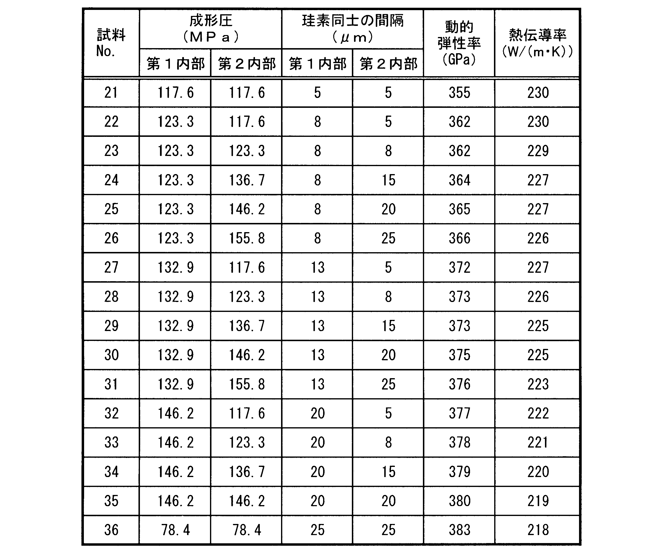
- Table 3 shows the pressure used in molding to obtain the first interior and the second interior as molding pressure. The mirror surface obtained by polishing the cross section including the first contact surface and the second contact surface of each sample was observed for the presence or absence of voids in the same manner as in Example 1. As a result, all samples had voids. Confirmed not.
- the distance between the centers of gravity of silicon in the first inner part and the second inner part of each sample was obtained by the following method. First, a sample including the first inner part and the second inner part was separately cut out, and an average range was selected from the mirror surface obtained by polishing the cross section of the sample using diamond abrasive grains. An observation image was obtained by photographing a range of 191 mm 2 (horizontal length: 351 ⁇ m, vertical length: 545 ⁇ m) with a CCD camera.
- the distance between the centers of gravity of silicon was measured using the image analysis software ⁇ Azo-kun (ver. asked for The setting conditions for this method were a threshold value of 190, which is an index indicating the brightness of the image, a brightness of light, a small figure removal area of 1 ⁇ m 2 , and a noise removal filter.
- the circle-equivalent diameter of silicon was obtained by a technique called particle analysis, using the observed image as a target.
- the setting conditions for this method were as follows: the threshold value, which is an index indicating the brightness of the image, was set to 195; the brightness was bright; the small figure removal area was 1 ⁇ m 2 ;
- the average value of the distance between the centers of gravity of silicon and the average value of the equivalent circle diameter were calculated, and the value obtained by subtracting the average value of the average equivalent circle diameter from the average value of the distance between the centers of gravity of silicon was shown in Table 3 as the silicon spacing.
- the distance between silicon atoms in at least one of the first interior and the second interior is 8 ⁇ m or more and 20 ⁇ m or less. Therefore, it has both a high dynamic elastic modulus and a high thermal conductivity, and it can be said that there is little bias in rigidity and thermal conductivity.
Landscapes
- Chemical & Material Sciences (AREA)
- Engineering & Computer Science (AREA)
- Ceramic Engineering (AREA)
- Manufacturing & Machinery (AREA)
- Materials Engineering (AREA)
- Structural Engineering (AREA)
- Organic Chemistry (AREA)
- Inorganic Chemistry (AREA)
- Mechanical Engineering (AREA)
- Chemical Kinetics & Catalysis (AREA)
- Ceramic Products (AREA)
Abstract
Description
工程(b):外面側に位置し酸化珪素を主成分として含む第2外層部、および第2外層部に囲繞される炭化珪素および珪素を含む第2内部を有する第2複合体を得る工程。
工程(c):第1内部が第2内部に当接する第1当接面、および第2内部が第1内部に当接する第2当接面の少なくとも一方を、研削または研磨する工程。
工程(d):第1当接面と第2当接面とを当接させ、真空雰囲気中または不活性ガス雰囲気中で熱処理する工程。
まず、第1複合体および第2複合体をそれぞれ作製した。拡散接合する前に、第1複合体の第1当接面および第2複合体の第2当接面とは、予め表1に示す状態の面になるようにした。第1当接面と第2当接面とを当接させ、真空雰囲気中で熱処理温度を1350℃として拡散接合して試料を得た。

まず、本実施形態の接合体からなる試料を準備した。各試料に含まれる炭化珪素および珪素の各含有量は、予め表2に示す値になるように調整した。各試料の第1内部および第2内部に含まれる各成分は、X線回折装置で同定し、炭化珪素および珪素の各含有量は、リートベルト法で求めた。炭化珪素および珪素以外の成分の含有量は、蛍光X線分析装置で求めた結果、その含有量の合計は0.1質量%以下であった。各試料について、動的弾性率および熱伝導率を測定した。

まず、本実施形態の接合体からなる試料を準備した。各試料に含まれる炭化珪素の含有量は81質量%、珪素の含有量は19質量%になるように調整した。ここで、第1内部および第2内部を得るために、成形する際に用いる圧力を成形圧として表3に示した。各試料の第1当接面および第2当接面を含む断面を研磨して得られる鏡面を実施例1で示した方法と同じ方法で空隙の有無を観察した結果、いずれの試料も空隙がないことを確認した。
1 第1複合体
11 第1外層部
12 第1内部
13 第1凹部
14 第1内層部
15 第1当接面
2 第2複合体
21 第2外層部
22 第2内部
23 第2凹部
24 第2内層部
25 第2当接面
Claims (8)
- 外面側に位置し酸化珪素を主成分として含む第1外層部、および該第1外層部に囲繞される炭化珪素および珪素を含む第1内部を有する第1複合体を得る工程と、
外面側に位置し酸化珪素を主成分として含む第2外層部、および該第2外層部に囲繞される炭化珪素および珪素を含む第2内部を有する第2複合体を得る工程と、
前記第1内部が前記第2内部に当接する第1当接面、および前記第2内部が前記第1内部に当接する第2当接面の少なくとも一方を、研削または研磨する工程と、
前記第1当接面と前記第2当接面とを当接させ、真空雰囲気中または不活性ガス雰囲気中で熱処理する工程と、
を含む、接合体の製造方法。 - 前記第1当接面が、深さ方向に向かって第1凹部または第1貫通孔を備える、請求項1に記載の接合体の製造方法。
- 前記第1複合体が、前記第1凹部の内壁面および内底面の少なくとも一方、または前記第1貫通孔の内壁面に、酸化珪素を主成分として含む第1内層部を備える、請求項2に記載の接合体の製造方法。
- 前記第2当接面が、深さ方向に向かって第2凹部または第2貫通孔を備える、請求項1~3のいずれかに記載の接合体の製造方法。
- 前記第2複合体が、前記第2凹部の内壁面および内底面の少なくとも一方、または前記第2貫通孔の内壁面に、酸化珪素を主成分として含む第2内層部を備える、請求項4に記載の接合体の製造方法。
- 前記第1内部および前記第2内部の少なくとも一方における炭化珪素の含有量が、70質量%以上92質量%以下である、請求項1~5のいずれかに記載の接合体の製造方法。
- 前記第1内部および前記第2内部の少なくとも一方において、珪素の重心間距離の平均値と珪素の円相当径の平均値との差が、8μm以上20μm以下である、請求項1~6のいずれかに記載の接合体の製造方法。
- 前記第1内部および前記第2内部の少なくとも一方の閉気孔率が、0.1%以下である、請求項1~7のいずれかに記載の接合体の製造方法。
Priority Applications (3)
| Application Number | Priority Date | Filing Date | Title |
|---|---|---|---|
| JP2023511223A JPWO2022210470A1 (ja) | 2021-03-29 | 2022-03-28 | |
| EP22780681.7A EP4317111A4 (en) | 2021-03-29 | 2022-03-28 | PROCESS FOR PRODUCING AN ASSEMBLY |
| US18/553,323 US20240182369A1 (en) | 2021-03-29 | 2022-03-28 | Method for manufacturing bonded body |
Applications Claiming Priority (2)
| Application Number | Priority Date | Filing Date | Title |
|---|---|---|---|
| JP2021-056172 | 2021-03-29 | ||
| JP2021056172 | 2021-03-29 |
Publications (1)
| Publication Number | Publication Date |
|---|---|
| WO2022210470A1 true WO2022210470A1 (ja) | 2022-10-06 |
Family
ID=83459057
Family Applications (1)
| Application Number | Title | Priority Date | Filing Date |
|---|---|---|---|
| PCT/JP2022/014812 Ceased WO2022210470A1 (ja) | 2021-03-29 | 2022-03-28 | 接合体の製造方法 |
Country Status (4)
| Country | Link |
|---|---|
| US (1) | US20240182369A1 (ja) |
| EP (1) | EP4317111A4 (ja) |
| JP (1) | JPWO2022210470A1 (ja) |
| WO (1) | WO2022210470A1 (ja) |
Citations (5)
| Publication number | Priority date | Publication date | Assignee | Title |
|---|---|---|---|---|
| JPH0274572A (ja) * | 1988-09-09 | 1990-03-14 | Ngk Insulators Ltd | 炭化珪素焼結体の接合方法 |
| JPH02107580A (ja) * | 1988-09-27 | 1990-04-19 | Norton Co | 炭化ケイ素部品の接合方法及び複合炭化ケイ素構造体 |
| JP2007153700A (ja) * | 2005-12-07 | 2007-06-21 | Toshiba Ceramics Co Ltd | 炭化ケイ素多孔質セラミックスの接合方法および接合部材 |
| JP2009078943A (ja) * | 2007-09-26 | 2009-04-16 | Covalent Materials Corp | 炭化ケイ素セラミックス材の接合方法 |
| JP2019055897A (ja) * | 2017-09-21 | 2019-04-11 | 日本特殊陶業株式会社 | 炭化珪素部材の製造方法 |
Family Cites Families (7)
| Publication number | Priority date | Publication date | Assignee | Title |
|---|---|---|---|---|
| DE3003186C2 (de) * | 1980-01-30 | 1983-01-27 | Dornier System Gmbh, 7990 Friedrichshafen | Anwendung des Diffusionsschweißens zur Verbindung von Bauteilen aus Siliciumverbundwerkstoffen |
| US4487644A (en) * | 1981-10-02 | 1984-12-11 | Kernforschungsanlage J/u/ lich | Binderless weld-bonding of preshaped sic-base parts into solid bodies |
| DE102004044942A1 (de) * | 2004-09-16 | 2006-03-30 | Esk Ceramics Gmbh & Co. Kg | Verfahren zum verformungsarmen Diffusionsschweißen von keramischen Komponenten |
| DE102011012834A1 (de) * | 2011-02-22 | 2012-08-23 | Fraunhofer-Gesellschaft zur Förderung der angewandten Forschung e.V. | Verfahren zur Herstellung von Leichtbaustrukturelementen |
| DE102011012835A1 (de) * | 2011-02-22 | 2012-08-23 | Friedrich-Schiller-Universität Jena | Verfahren zum Fügen von Substraten |
| JP2013075799A (ja) * | 2011-09-30 | 2013-04-25 | Taiheiyo Cement Corp | SiC/Si複合材料体の接合方法及びSiC/Si複合材料接合体 |
| JP5869437B2 (ja) * | 2012-06-28 | 2016-02-24 | 株式会社日本セラテック | SiC焼結体の接合方法 |
-
2022
- 2022-03-28 EP EP22780681.7A patent/EP4317111A4/en not_active Withdrawn
- 2022-03-28 WO PCT/JP2022/014812 patent/WO2022210470A1/ja not_active Ceased
- 2022-03-28 US US18/553,323 patent/US20240182369A1/en not_active Abandoned
- 2022-03-28 JP JP2023511223A patent/JPWO2022210470A1/ja active Pending
Patent Citations (6)
| Publication number | Priority date | Publication date | Assignee | Title |
|---|---|---|---|---|
| JPH0274572A (ja) * | 1988-09-09 | 1990-03-14 | Ngk Insulators Ltd | 炭化珪素焼結体の接合方法 |
| JPH02107580A (ja) * | 1988-09-27 | 1990-04-19 | Norton Co | 炭化ケイ素部品の接合方法及び複合炭化ケイ素構造体 |
| JP2007153700A (ja) * | 2005-12-07 | 2007-06-21 | Toshiba Ceramics Co Ltd | 炭化ケイ素多孔質セラミックスの接合方法および接合部材 |
| JP2009078943A (ja) * | 2007-09-26 | 2009-04-16 | Covalent Materials Corp | 炭化ケイ素セラミックス材の接合方法 |
| JP4954838B2 (ja) | 2007-09-26 | 2012-06-20 | コバレントマテリアル株式会社 | 炭化ケイ素セラミックス材の接合方法 |
| JP2019055897A (ja) * | 2017-09-21 | 2019-04-11 | 日本特殊陶業株式会社 | 炭化珪素部材の製造方法 |
Non-Patent Citations (1)
| Title |
|---|
| See also references of EP4317111A4 |
Also Published As
| Publication number | Publication date |
|---|---|
| JPWO2022210470A1 (ja) | 2022-10-06 |
| EP4317111A4 (en) | 2025-04-09 |
| EP4317111A1 (en) | 2024-02-07 |
| US20240182369A1 (en) | 2024-06-06 |
Similar Documents
| Publication | Publication Date | Title |
|---|---|---|
| JP5666748B1 (ja) | 冷却板、その製法及び半導体製造装置用部材 | |
| RU2505378C2 (ru) | Алюминиево-алмазный композиционный материал и способ его получения | |
| JP5729517B1 (ja) | 反応焼結炭化珪素部材 | |
| JP5759152B2 (ja) | アルミニウム−ダイヤモンド系複合体及びその製造方法 | |
| US7218502B2 (en) | Bonding member and electrostatic chuck | |
| JP6708460B2 (ja) | 接合体の製造方法 | |
| Johnson et al. | Effect of liquid content on distortion and rearrangement densification of liquid-phase-sintered W-Cu | |
| JPH07332367A (ja) | 三様式の細孔構成を有する多孔性SiCのベアリング材料及びその製造方法 | |
| TWI862772B (zh) | 接合材、接合材的製造方法及接合體 | |
| CN102498233A (zh) | 金属氧化物-金属复合溅射靶 | |
| WO2007074720A1 (ja) | 半導体素子実装用基板とそれを用いた半導体装置および半導体素子実装用基板の製造方法 | |
| WO2019194137A1 (ja) | SiC-Siコンポジット部材の製造方法およびSiC-Siコンポジット部材 | |
| JP2008132562A (ja) | 真空チャックおよびこれを用いた真空吸着装置 | |
| JP2004515648A (ja) | 金属とセラミックとの複合体からなる薄膜の製造方法 | |
| JP5231064B2 (ja) | 真空吸着装置及びその製造方法 | |
| CN113084176A (zh) | 一种自支撑金刚石膜/Cu复合热沉材料及其制备方法 | |
| US5203488A (en) | Method for joining ceramic composite bodies and articles formed thereby | |
| JP2017024161A (ja) | 研磨工具及びその製造方法並びに研磨物の製造方法 | |
| JP4624690B2 (ja) | 切削工具用インサート及びその製造方法 | |
| US20240182369A1 (en) | Method for manufacturing bonded body | |
| JP7583686B2 (ja) | 吸着用部材およびその製造方法 | |
| JP5046859B2 (ja) | 接合体、吸着部材、吸着装置および加工装置 | |
| JP6236314B2 (ja) | 炭化珪素接合体及びその製造方法 | |
| JP2005118979A (ja) | 研削・研磨用真空チャックおよび吸着板 | |
| JP5275292B2 (ja) | 高密度固化成形体の製造方法 |
Legal Events
| Date | Code | Title | Description |
|---|---|---|---|
| 121 | Ep: the epo has been informed by wipo that ep was designated in this application |
Ref document number: 22780681 Country of ref document: EP Kind code of ref document: A1 |
|
| WWE | Wipo information: entry into national phase |
Ref document number: 2023511223 Country of ref document: JP |
|
| WWE | Wipo information: entry into national phase |
Ref document number: 18553323 Country of ref document: US |
|
| WWE | Wipo information: entry into national phase |
Ref document number: 2022780681 Country of ref document: EP |
|
| NENP | Non-entry into the national phase |
Ref country code: DE |
|
| ENP | Entry into the national phase |
Ref document number: 2022780681 Country of ref document: EP Effective date: 20231030 |
|
| WWW | Wipo information: withdrawn in national office |
Ref document number: 2022780681 Country of ref document: EP |