WO2022210647A1 - ポリプロピレン系樹脂押出発泡粒子の製造方法 - Google Patents
ポリプロピレン系樹脂押出発泡粒子の製造方法 Download PDFInfo
- Publication number
- WO2022210647A1 WO2022210647A1 PCT/JP2022/015295 JP2022015295W WO2022210647A1 WO 2022210647 A1 WO2022210647 A1 WO 2022210647A1 JP 2022015295 W JP2022015295 W JP 2022015295W WO 2022210647 A1 WO2022210647 A1 WO 2022210647A1
- Authority
- WO
- WIPO (PCT)
- Prior art keywords
- resin
- polypropylene
- extruded
- die
- composition
- Prior art date
- Legal status (The legal status is an assumption and is not a legal conclusion. Google has not performed a legal analysis and makes no representation as to the accuracy of the status listed.)
- Ceased
Links
Images

Classifications
-
- B—PERFORMING OPERATIONS; TRANSPORTING
- B29—WORKING OF PLASTICS; WORKING OF SUBSTANCES IN A PLASTIC STATE IN GENERAL
- B29B—PREPARATION OR PRETREATMENT OF THE MATERIAL TO BE SHAPED; MAKING GRANULES OR PREFORMS; RECOVERY OF PLASTICS OR OTHER CONSTITUENTS OF WASTE MATERIAL CONTAINING PLASTICS
- B29B9/00—Making granules
- B29B9/12—Making granules characterised by structure or composition
-
- B—PERFORMING OPERATIONS; TRANSPORTING
- B29—WORKING OF PLASTICS; WORKING OF SUBSTANCES IN A PLASTIC STATE IN GENERAL
- B29B—PREPARATION OR PRETREATMENT OF THE MATERIAL TO BE SHAPED; MAKING GRANULES OR PREFORMS; RECOVERY OF PLASTICS OR OTHER CONSTITUENTS OF WASTE MATERIAL CONTAINING PLASTICS
- B29B7/00—Mixing; Kneading
- B29B7/30—Mixing; Kneading continuous, with mechanical mixing or kneading devices
- B29B7/58—Component parts, details or accessories; Auxiliary operations
- B29B7/582—Component parts, details or accessories; Auxiliary operations for discharging, e.g. doors
-
- B—PERFORMING OPERATIONS; TRANSPORTING
- B29—WORKING OF PLASTICS; WORKING OF SUBSTANCES IN A PLASTIC STATE IN GENERAL
- B29B—PREPARATION OR PRETREATMENT OF THE MATERIAL TO BE SHAPED; MAKING GRANULES OR PREFORMS; RECOVERY OF PLASTICS OR OTHER CONSTITUENTS OF WASTE MATERIAL CONTAINING PLASTICS
- B29B7/00—Mixing; Kneading
- B29B7/30—Mixing; Kneading continuous, with mechanical mixing or kneading devices
- B29B7/58—Component parts, details or accessories; Auxiliary operations
- B29B7/72—Measuring, controlling or regulating
- B29B7/726—Measuring properties of mixture, e.g. temperature or density
-
- B—PERFORMING OPERATIONS; TRANSPORTING
- B29—WORKING OF PLASTICS; WORKING OF SUBSTANCES IN A PLASTIC STATE IN GENERAL
- B29B—PREPARATION OR PRETREATMENT OF THE MATERIAL TO BE SHAPED; MAKING GRANULES OR PREFORMS; RECOVERY OF PLASTICS OR OTHER CONSTITUENTS OF WASTE MATERIAL CONTAINING PLASTICS
- B29B7/00—Mixing; Kneading
- B29B7/80—Component parts, details or accessories; Auxiliary operations
- B29B7/88—Adding charges, i.e. additives
-
- B—PERFORMING OPERATIONS; TRANSPORTING
- B29—WORKING OF PLASTICS; WORKING OF SUBSTANCES IN A PLASTIC STATE IN GENERAL
- B29C—SHAPING OR JOINING OF PLASTICS; SHAPING OF MATERIAL IN A PLASTIC STATE, NOT OTHERWISE PROVIDED FOR; AFTER-TREATMENT OF THE SHAPED PRODUCTS, e.g. REPAIRING
- B29C44/00—Shaping by internal pressure generated in the material, e.g. swelling or foaming ; Producing porous or cellular expanded plastics articles
- B29C44/34—Auxiliary operations
- B29C44/3461—Making or treating expandable particles
-
- C—CHEMISTRY; METALLURGY
- C08—ORGANIC MACROMOLECULAR COMPOUNDS; THEIR PREPARATION OR CHEMICAL WORKING-UP; COMPOSITIONS BASED THEREON
- C08J—WORKING-UP; GENERAL PROCESSES OF COMPOUNDING; AFTER-TREATMENT NOT COVERED BY SUBCLASSES C08B, C08C, C08F, C08G or C08H
- C08J3/00—Processes of treating or compounding macromolecular substances
- C08J3/12—Powdering or granulating
-
- C—CHEMISTRY; METALLURGY
- C08—ORGANIC MACROMOLECULAR COMPOUNDS; THEIR PREPARATION OR CHEMICAL WORKING-UP; COMPOSITIONS BASED THEREON
- C08J—WORKING-UP; GENERAL PROCESSES OF COMPOUNDING; AFTER-TREATMENT NOT COVERED BY SUBCLASSES C08B, C08C, C08F, C08G or C08H
- C08J9/00—Working-up of macromolecular substances to porous or cellular articles or materials; After-treatment thereof
- C08J9/04—Working-up of macromolecular substances to porous or cellular articles or materials; After-treatment thereof using blowing gases generated by a previously added blowing agent
- C08J9/12—Working-up of macromolecular substances to porous or cellular articles or materials; After-treatment thereof using blowing gases generated by a previously added blowing agent by a physical blowing agent
- C08J9/122—Hydrogen, oxygen, CO2, nitrogen or noble gases
-
- C—CHEMISTRY; METALLURGY
- C08—ORGANIC MACROMOLECULAR COMPOUNDS; THEIR PREPARATION OR CHEMICAL WORKING-UP; COMPOSITIONS BASED THEREON
- C08J—WORKING-UP; GENERAL PROCESSES OF COMPOUNDING; AFTER-TREATMENT NOT COVERED BY SUBCLASSES C08B, C08C, C08F, C08G or C08H
- C08J9/00—Working-up of macromolecular substances to porous or cellular articles or materials; After-treatment thereof
- C08J9/16—Making expandable particles
-
- C—CHEMISTRY; METALLURGY
- C08—ORGANIC MACROMOLECULAR COMPOUNDS; THEIR PREPARATION OR CHEMICAL WORKING-UP; COMPOSITIONS BASED THEREON
- C08J—WORKING-UP; GENERAL PROCESSES OF COMPOUNDING; AFTER-TREATMENT NOT COVERED BY SUBCLASSES C08B, C08C, C08F, C08G or C08H
- C08J9/00—Working-up of macromolecular substances to porous or cellular articles or materials; After-treatment thereof
- C08J9/22—After-treatment of expandable particles; Forming foamed products
- C08J9/228—Forming foamed products
- C08J9/232—Forming foamed products by sintering expandable particles
-
- B—PERFORMING OPERATIONS; TRANSPORTING
- B29—WORKING OF PLASTICS; WORKING OF SUBSTANCES IN A PLASTIC STATE IN GENERAL
- B29B—PREPARATION OR PRETREATMENT OF THE MATERIAL TO BE SHAPED; MAKING GRANULES OR PREFORMS; RECOVERY OF PLASTICS OR OTHER CONSTITUENTS OF WASTE MATERIAL CONTAINING PLASTICS
- B29B7/00—Mixing; Kneading
- B29B7/30—Mixing; Kneading continuous, with mechanical mixing or kneading devices
- B29B7/34—Mixing; Kneading continuous, with mechanical mixing or kneading devices with movable mixing or kneading devices
- B29B7/38—Mixing; Kneading continuous, with mechanical mixing or kneading devices with movable mixing or kneading devices rotary
- B29B7/46—Mixing; Kneading continuous, with mechanical mixing or kneading devices with movable mixing or kneading devices rotary with more than one shaft
- B29B7/48—Mixing; Kneading continuous, with mechanical mixing or kneading devices with movable mixing or kneading devices rotary with more than one shaft with intermeshing devices, e.g. screws
-
- B—PERFORMING OPERATIONS; TRANSPORTING
- B29—WORKING OF PLASTICS; WORKING OF SUBSTANCES IN A PLASTIC STATE IN GENERAL
- B29B—PREPARATION OR PRETREATMENT OF THE MATERIAL TO BE SHAPED; MAKING GRANULES OR PREFORMS; RECOVERY OF PLASTICS OR OTHER CONSTITUENTS OF WASTE MATERIAL CONTAINING PLASTICS
- B29B9/00—Making granules
- B29B9/02—Making granules by dividing preformed material
- B29B9/06—Making granules by dividing preformed material in the form of filamentary material, e.g. combined with extrusion
-
- B—PERFORMING OPERATIONS; TRANSPORTING
- B29—WORKING OF PLASTICS; WORKING OF SUBSTANCES IN A PLASTIC STATE IN GENERAL
- B29B—PREPARATION OR PRETREATMENT OF THE MATERIAL TO BE SHAPED; MAKING GRANULES OR PREFORMS; RECOVERY OF PLASTICS OR OTHER CONSTITUENTS OF WASTE MATERIAL CONTAINING PLASTICS
- B29B9/00—Making granules
- B29B9/02—Making granules by dividing preformed material
- B29B9/06—Making granules by dividing preformed material in the form of filamentary material, e.g. combined with extrusion
- B29B9/065—Making granules by dividing preformed material in the form of filamentary material, e.g. combined with extrusion under-water, e.g. underwater pelletizers
-
- B—PERFORMING OPERATIONS; TRANSPORTING
- B29—WORKING OF PLASTICS; WORKING OF SUBSTANCES IN A PLASTIC STATE IN GENERAL
- B29C—SHAPING OR JOINING OF PLASTICS; SHAPING OF MATERIAL IN A PLASTIC STATE, NOT OTHERWISE PROVIDED FOR; AFTER-TREATMENT OF THE SHAPED PRODUCTS, e.g. REPAIRING
- B29C48/00—Extrusion moulding, i.e. expressing the moulding material through a die or nozzle which imparts the desired form; Apparatus therefor
- B29C48/03—Extrusion moulding, i.e. expressing the moulding material through a die or nozzle which imparts the desired form; Apparatus therefor characterised by the shape of the extruded material at extrusion
- B29C48/04—Particle-shaped
-
- B—PERFORMING OPERATIONS; TRANSPORTING
- B29—WORKING OF PLASTICS; WORKING OF SUBSTANCES IN A PLASTIC STATE IN GENERAL
- B29C—SHAPING OR JOINING OF PLASTICS; SHAPING OF MATERIAL IN A PLASTIC STATE, NOT OTHERWISE PROVIDED FOR; AFTER-TREATMENT OF THE SHAPED PRODUCTS, e.g. REPAIRING
- B29C48/00—Extrusion moulding, i.e. expressing the moulding material through a die or nozzle which imparts the desired form; Apparatus therefor
- B29C48/03—Extrusion moulding, i.e. expressing the moulding material through a die or nozzle which imparts the desired form; Apparatus therefor characterised by the shape of the extruded material at extrusion
- B29C48/05—Filamentary, e.g. strands
-
- B—PERFORMING OPERATIONS; TRANSPORTING
- B29—WORKING OF PLASTICS; WORKING OF SUBSTANCES IN A PLASTIC STATE IN GENERAL
- B29C—SHAPING OR JOINING OF PLASTICS; SHAPING OF MATERIAL IN A PLASTIC STATE, NOT OTHERWISE PROVIDED FOR; AFTER-TREATMENT OF THE SHAPED PRODUCTS, e.g. REPAIRING
- B29C48/00—Extrusion moulding, i.e. expressing the moulding material through a die or nozzle which imparts the desired form; Apparatus therefor
- B29C48/25—Component parts, details or accessories; Auxiliary operations
- B29C48/30—Extrusion nozzles or dies
- B29C48/345—Extrusion nozzles comprising two or more adjacently arranged ports, for simultaneously extruding multiple strands, e.g. for pelletising
-
- C—CHEMISTRY; METALLURGY
- C08—ORGANIC MACROMOLECULAR COMPOUNDS; THEIR PREPARATION OR CHEMICAL WORKING-UP; COMPOSITIONS BASED THEREON
- C08J—WORKING-UP; GENERAL PROCESSES OF COMPOUNDING; AFTER-TREATMENT NOT COVERED BY SUBCLASSES C08B, C08C, C08F, C08G or C08H
- C08J2203/00—Foams characterized by the expanding agent
- C08J2203/06—CO2, N2 or noble gases
-
- C—CHEMISTRY; METALLURGY
- C08—ORGANIC MACROMOLECULAR COMPOUNDS; THEIR PREPARATION OR CHEMICAL WORKING-UP; COMPOSITIONS BASED THEREON
- C08J—WORKING-UP; GENERAL PROCESSES OF COMPOUNDING; AFTER-TREATMENT NOT COVERED BY SUBCLASSES C08B, C08C, C08F, C08G or C08H
- C08J2323/00—Characterised by the use of homopolymers or copolymers of unsaturated aliphatic hydrocarbons having only one carbon-to-carbon double bond; Derivatives of such polymers
- C08J2323/02—Characterised by the use of homopolymers or copolymers of unsaturated aliphatic hydrocarbons having only one carbon-to-carbon double bond; Derivatives of such polymers not modified by chemical after treatment
- C08J2323/10—Homopolymers or copolymers of propene
- C08J2323/12—Polypropene
-
- C—CHEMISTRY; METALLURGY
- C08—ORGANIC MACROMOLECULAR COMPOUNDS; THEIR PREPARATION OR CHEMICAL WORKING-UP; COMPOSITIONS BASED THEREON
- C08J—WORKING-UP; GENERAL PROCESSES OF COMPOUNDING; AFTER-TREATMENT NOT COVERED BY SUBCLASSES C08B, C08C, C08F, C08G or C08H
- C08J2323/00—Characterised by the use of homopolymers or copolymers of unsaturated aliphatic hydrocarbons having only one carbon-to-carbon double bond; Derivatives of such polymers
- C08J2323/02—Characterised by the use of homopolymers or copolymers of unsaturated aliphatic hydrocarbons having only one carbon-to-carbon double bond; Derivatives of such polymers not modified by chemical after treatment
- C08J2323/10—Homopolymers or copolymers of propene
- C08J2323/14—Copolymers of propene
-
- C—CHEMISTRY; METALLURGY
- C08—ORGANIC MACROMOLECULAR COMPOUNDS; THEIR PREPARATION OR CHEMICAL WORKING-UP; COMPOSITIONS BASED THEREON
- C08J—WORKING-UP; GENERAL PROCESSES OF COMPOUNDING; AFTER-TREATMENT NOT COVERED BY SUBCLASSES C08B, C08C, C08F, C08G or C08H
- C08J2423/00—Characterised by the use of homopolymers or copolymers of unsaturated aliphatic hydrocarbons having only one carbon-to-carbon double bond; Derivatives of such polymers
- C08J2423/02—Characterised by the use of homopolymers or copolymers of unsaturated aliphatic hydrocarbons having only one carbon-to-carbon double bond; Derivatives of such polymers not modified by chemical after treatment
- C08J2423/10—Homopolymers or copolymers of propene
-
- C—CHEMISTRY; METALLURGY
- C08—ORGANIC MACROMOLECULAR COMPOUNDS; THEIR PREPARATION OR CHEMICAL WORKING-UP; COMPOSITIONS BASED THEREON
- C08J—WORKING-UP; GENERAL PROCESSES OF COMPOUNDING; AFTER-TREATMENT NOT COVERED BY SUBCLASSES C08B, C08C, C08F, C08G or C08H
- C08J9/00—Working-up of macromolecular substances to porous or cellular articles or materials; After-treatment thereof
- C08J9/0061—Working-up of macromolecular substances to porous or cellular articles or materials; After-treatment thereof characterized by the use of several polymeric components
Definitions
- the present invention relates to a method for producing extruded polypropylene resin expanded particles.
- a polypropylene resin-based in-mold expansion-molded article obtained using polypropylene-based resin expanded particles has the advantages of an in-mold expansion-molded article, such as arbitrariness of shape, shock-absorbing properties, light weight, and heat insulating properties.
- Examples of methods for producing expanded polypropylene resin particles include a batch foaming method, which is a discontinuous process, and an extrusion foaming method, which is a continuous process.
- the extrusion foaming method has many advantages in terms of efficiency, environment, etc., but has a problem that it is difficult to obtain foamed polypropylene resin particles with good moldability.
- Patent Document 1 discloses a method for producing expanded particles of a thermoplastic resin by an extrusion expansion method by adjusting the diameter of the expanded particles within a specific range.
- One embodiment of the present invention has been made in view of the above-mentioned problems, and its object is to provide a method for producing extruded polypropylene resin expanded beads that can provide polypropylene resin expanded beads excellent in moldability with good productivity. to provide.
- a composition containing a resin mixture containing a polypropylene resin having a branched structure and a foaming agent is extruded using an extruder equipped with a die.
- the composition of the inlet portion of the die is The pressure of the article is 14.5 MPa or more, and the discharge rate of the composition per hole of the die is more than 2.5 kg/hr and less than or equal to 5.0 kg/hr.
- FIG. 4 is a cross-sectional view showing the configuration near the outlet of the die used in one embodiment of the present invention.
- the depressurized foaming method which is a batch foaming method, includes a step of melt-kneading a polypropylene resin and extruding to obtain polypropylene resin particles, and the obtained polypropylene resin particles.
- a foaming step is required in which the particles are pressurized and heated together with an inorganic dispersant and a foaming agent in an aqueous solvent, impregnated with the foaming agent into the resin, and then released under a low pressure to foam.
- the depressurized foaming method has the problem that the process is complicated because it is a discontinuous process, and the problem that a wastewater treatment facility is required due to the use of an inorganic dispersant, which requires a large facility site.
- extrusion foaming method a composition containing a thermoplastic resin and a foaming agent is supplied to an extruder, and the composition is melt-kneaded and optionally cooled to form a melt-kneaded composition (hereinafter “expandable melt (also referred to as "resin”) is obtained. Thereafter, the composition is extruded into a low-pressure region through a die attached to the tip of the extruder and finely chopped to obtain foamed particles of thermoplastic resin.
- expandable melt also referred to as "resin”
- the extrusion foaming method is (a) a continuous process that can simplify the process, and (b) does not require a large facility site such as a wastewater treatment facility.
- a production base can be set up near the place of demand, and transportation and labor costs can be reduced. Therefore, the extrusion foaming method has many advantages in terms of efficiency, environment, etc., and it is possible to produce expanded polypropylene resin particles at low cost.
- the extrusion foaming method using carbon dioxide gas which has less environmental impact, as a foaming agent has a lower gas retention during foaming than the extrusion foaming method using an organic foaming agent. For this reason, it is particularly difficult to obtain polypropylene-based resin expanded particles with good moldability by the extrusion foaming method using carbon dioxide gas.
- the shredding method (granulation method) for obtaining expanded particles in the extrusion foaming method is roughly divided into the cold cut method and the die face cut method.
- the die face cut method is a method in which a composition extruded from a die is cut with a rotating cutter while being in contact with the face of the die or with a slight gap secured.
- the die face cutting method can be further divided into the following three methods according to the difference in cooling method. That is, under water cut (hereinafter sometimes referred to as UWC) method, water ring cut (hereinafter sometimes referred to as WRC) method, and hot cut (hereinafter sometimes referred to as HC) method is.
- UWC under water cut
- WRC water ring cut
- HC hot cut
- a chamber attached to the tip of the die is filled with a liquid cooling medium (e.g., water) adjusted to a predetermined pressure so as to be in contact with the face of the die, and the molten resin extruded from the hole of the die is poured into the cooling medium. It is a method of cutting in the middle (for example, in water).
- the UWC process is characterized in that the cooling medium is also used to cool the resin while conveying it to subsequent equipment (a water separator).
- a composition obtained by melt-kneading in an extruder (also referred to as a molten resin) is extruded through a die into a liquid phase (in a liquid cooling medium, for example, water), and immediately after the die and into the liquid
- a chopping unit for example, a cutter, etc.
- the inventors of the present invention have found that in the UWC method, productivity can be improved while maintaining good moldability of extruded polypropylene resin foam particles (for example, the amount of composition discharged per die hole is 1.2 kg /hr), an intensive study was carried out.
- the present inventors have independently found the following knowledge and completed the present invention:
- the composition A composition containing a polypropylene-based resin having a branched structure and carbon dioxide gas is used as the substance, and (a) the temperature of the liquid phase and (b) the pressure of the composition at the inlet of the die are each controlled within an appropriate range.
- the present inventor investigated the reason why the moldability of the extruded expanded particles can be improved by the above (a) to (c). As a result, the inventors speculated the cause as follows: (1) Under high production conditions in which the discharge rate of foamable molten resin per die hole exceeds 1.2 kg/hr and is 2.5 kg/hr or less, the preparation time for foaming is longer than the preparation time for solidification. It is assumed that If the foaming preparation time is longer than the solidification preparation time, it is presumed that solidification by cooling of the foamable molten resin starts before foaming of the foamable molten resin starts (that is, before the cells start to swell).
- the cell membrane When the cells expand due to foaming in a state in which the resin becomes difficult to stretch due to solidification, the cell membrane is likely to break. Polypropylene-based resin extruded expanded particles containing many broken cell membranes are inferior in moldability; (2) As the foamable molten resin, a polypropylene-based resin having a branched structure and a foamable molten resin containing carbon dioxide gas are used, and the above (a) and (b) are controlled within appropriate ranges. It is presumed that the preparation time for solidification becomes longer than the preparation time for foaming by setting the discharge amount of foamable molten resin per hole to be more than 2.5 kg/hr and 5.0 kg/hr or less.
- the preparation time for solidification is longer than the preparation time for foaming, it is presumed that solidification starts while the cells are expanded by foaming or after the cells are sufficiently expanded by foaming. Therefore, the obtained extruded polypropylene-based resin particles retain cell membranes and exhibit excellent moldability. It should be noted that the present invention is by no means limited to such speculation.
- the “foaming preparation time” means the time it takes from when the foamable molten resin is discharged into the liquid phase to when foaming starts.
- the “foaming preparation time” is the time required for the pressure of the foaming agent in the foamable molten resin discharged into the liquid phase to decrease to the pressure at which foaming can start (saturation pressure of carbon dioxide gas). , can also be said.
- the “preparation time for solidification” means the time it takes for the foamable molten resin to start solidifying after being discharged into the liquid phase.
- the “preparation time for solidification” can be said to be the time required for the temperature of the foamable molten resin discharged into the liquid phase to drop to the temperature at which solidification can start (the melting point of the resin mixture). It should be noted that the present invention is not limited in any way by such presumption.
- Moldability in this specification is a property of extruded polypropylene resin foam particles and means ease of molding.
- good moldability means that it is easy to further expand the extruded polypropylene resin particles and fuse the extruded particles to each other during in-mold foam molding. That is, the phrase "good moldability" in the present specification means that a polypropylene resin-based in-mold expansion-molded article having a high expansion ratio and excellent fusion bondability can be easily obtained.
- the moldability is evaluated by the 50% compressive strength of extruded polypropylene resin foam particles. The method for evaluating the 50% compressive strength will be described in detail in Examples below.
- a method for producing extruded expanded polypropylene resin expanded particles uses an extruder equipped with a die to melt-knead a composition containing a resin mixture containing a polypropylene-based resin having a branched structure and a foaming agent.
- the "liquid phase region” may be referred to as the "liquid phase region”
- the "polypropylene resin having a branched structure” may be referred to as the "branched polypropylene resin”.
- "Extruded resin expanded particles” may be referred to as “extruded expanded particles”
- "a composition containing a resin mixture containing a polypropylene-based resin having a branched structure and carbon dioxide gas as a blowing agent” is referred to as a “composition”.
- the "method for producing extruded polypropylene-based resin expanded particles according to one embodiment of the present invention” may be referred to as "this production method”.
- this manufacturing method has the configuration described above, it has the advantage of being able to obtain extruded polypropylene-based resin expanded particles with excellent moldability with high productivity. More specifically, according to the present production method, in the underwater cut method, even under high production conditions in which the discharge amount of the composition per hole of the die is increased, moldability is excellent. It has the advantage of being able to obtain extruded polypropylene-based resin particles.
- the resin mixture containing a polypropylene-based resin having a branched structure can be said to be a component other than the foaming agent in the composition.
- the resin mixture contains a polypropylene-based resin having a branched structure, and may optionally contain additives such as cell nucleating agents and colorants.
- polypropylene resin having a branched structure refers to (a) a polypropylene resin obtained by partially cross-linking the molecules of a polypropylene resin to which no branched structure has been introduced, and (b) A polypropylene resin in which a diene compound other than (poly)propylene or the like is introduced as a branched chain is intended for a polypropylene resin in which no branched structure is introduced.
- the polypropylene resin having a branched structure means a polypropylene resin having a loss tangent tan ⁇ of 5 or less at 200° C. and 0.1 rad/s. Other aspects (measurement method, etc.) of the loss tangent tan ⁇ will be described in detail in the section (polypropylene resin having a branched structure) below.
- polypropylene-based resin into which no branched structure is introduced may be referred to as "linear polypropylene-based resin", and the "polypropylene-based resin having a branched structure” is referred to as "branched polypropylene-based resin”.
- linear polypropylene resin and branched polypropylene resin may be collectively referred to as “polypropylene resin”.
- the linear polypropylene-based resin can also be said to be a raw material for the branched polypropylene-based resin.
- the linear polypropylene-based resin means a resin containing 50 mol% or more of structural units derived from a propylene monomer out of 100 mol% of all structural units contained in the resin.
- structural unit derived from propylene monomer may be referred to as "propylene unit”.
- the linear polypropylene resin may be (a) a homopolymer of propylene, or (b) a block copolymer, alternating copolymer, random copolymer or graft of propylene and a monomer other than propylene. It may be a copolymer or (c) a mixture of two or more thereof.
- the linear polypropylene resin may have one or more structural units derived from a monomer other than the propylene monomer, or may have one or more types.
- “Monomers other than propylene monomers” used in the production of linear polypropylene resins are sometimes referred to as “comonomers”, and “monomers other than propylene monomers” contained in linear polypropylene resins Structural unit derived from” may be referred to as "comonomer unit".
- Comonomers include monomers such as: (a) ethylene, 1-butene, isobutene, 1-pentene, 3-methyl-1-butene, 1-hexene, 4-methyl-1-pentene, ⁇ -olefins having 2 or 4 to 12 carbon atoms such as 3,4-dimethyl-1-butene, 1-heptene, 3-methyl-1-hexene, 1-octene, 1-decene, (b) cyclopentene, norbornene, Cyclic olefins such as tetracyclo[6,2,11,8,13,6]-4-dodecene, (c) 5-methylene-2-norbornene, 5-ethylidene-2-norbornene, 1,4-hexadiene, methyl- dienes such as 1,4-hexadiene, 7-methyl-1,6-octadiene, and (d) vinyl chloride, vinylidene chloride, acrylonitrile, meth
- Acrylic esters include methyl acrylate, ethyl acrylate, butyl acrylate, hexyl acrylate, 2-ethylhexyl acrylate, lauryl acrylate, stearyl acrylate, 2-hydroxyethyl acrylate, 2-hydroxypropyl acrylate and and glycidyl acrylate.
- Methacrylates include methyl methacrylate, ethyl methacrylate, butyl methacrylate, hexyl methacrylate, 2-ethylhexyl methacrylate, lauryl methacrylate, stearyl methacrylate, 2-hydroxyethyl methacrylate, 2-hydroxypropyl methacrylate and and glycidyl methacrylate.
- Styrenic monomers include styrene, methylstyrene, dimethylstyrene, alphamethylstyrene, paramethylstyrene, ethylstyrene, diethylstyrene, isopropylstyrene, t-butylstyrene, bromostyrene, dibromostyrene, tribromostyrene, chlorostyrene. , dichlorostyrene and trichlorostyrene.
- Linear polypropylene resin as a comonomer unit, preferably has a structural unit derived from an ⁇ -olefin having 2 or 4 to 12 carbon atoms, ethylene, 1-butene, isobutene, 1-pentene, 3-methyl-1 -butene, 1-hexene, 4-methyl-1-pentene, 3,4-dimethyl-1-butene, 1-heptene, 3-methyl-1-hexene, 1-octene and/or 1-decene, etc.
- this configuration (a) the advantage that a branched polypropylene resin having a high melt tension and a low gel fraction can be obtained, and (b) the obtained branched polypropylene resin has excellent moldability. It has the advantage of being able to provide particles.
- the linear polypropylene-based resin is preferably a propylene homopolymer, a polypropylene-based block copolymer, a polypropylene-based alternating copolymer and/or a polypropylene-based random copolymer, and a propylene homopolymer and/or a polypropylene-based random A copolymer is more preferred.
- a branched polypropylene resin having a high melt tension and a low gel fraction can be obtained
- the obtained branched polypropylene resin has excellent moldability. It has the advantage of being able to provide particles.
- the linear polypropylene resin preferably contains 90 mol% or more of propylene units, more preferably 93 mol% or more, and 95 mol% or more of all 100 mol% of the total structural units contained in the linear polypropylene resin. It is more preferable to contain it, and it is particularly preferable to contain it in an amount of 97 mol % or more. This configuration has the advantage of obtaining a branched polypropylene resin having a high melt tension and a low gel fraction.
- the melting point of the linear polypropylene resin is not particularly limited.
- the melting point of the linear polypropylene resin is, for example, preferably 130° C. to 165° C., more preferably 135° C. to 164° C., even more preferably 138° C. to 163° C., and 140° C. to 162° C. °C is particularly preferred.
- the melting point of the linear polypropylene-based resin is within the range described above, (a) the extruded foamed particles obtained have the advantage of being excellent in moldability, and (b) the extruded foamed particles provide a foamed molded product with excellent breakage resistance.
- the melting point of the linear polypropylene-based resin is (a) 130° C. or higher, there is no risk of deterioration in the dimensional stability of the foam-molded product, and there is no risk of insufficient heat resistance of the foam-molded product. It has the advantage that the compression strength of the molded body tends to be strong, and (b) when the temperature is 165 ° C. or less, it is possible to mold the extruded expanded particles at a relatively low steam pressure, so the polypropylene resin is extruded. It has the advantage that extruded foam particles can be molded using a general purpose molding machine for foam particles.
- the melting point of the linear polypropylene-based resin is a value obtained by measuring with a differential scanning calorimeter method (hereinafter referred to as "DSC method").
- DSC method differential scanning calorimeter method
- the specific operating procedure is as follows: (1) 5 to 6 mg of the linear polypropylene resin is heated from 40° C. to 220° C. at a rate of 10° C./min to obtain the linear polypropylene. (2) Then, the temperature of the melted linear polypropylene resin is lowered from 220° C. to 40° C. at a rate of 10° C./min to crystallize the linear polypropylene resin.
- the temperature of the crystallized linear polypropylene resin is further increased from 40°C to 220°C at a rate of temperature increase of 10°C/min.
- the temperature of the peak (melting peak) of the DSC curve of the linear polypropylene-based resin obtained during the second heating can be obtained as the melting point of the linear polypropylene-based resin. If there are multiple peaks (melting peaks) in the DSC curve of the linear polypropylene resin obtained during the second heating by the above method, the temperature of the peak (melting peak) with the maximum amount of heat of fusion is , the melting point of the linear polypropylene resin.
- the differential scanning calorimeter for example, DSC6200 type manufactured by Seiko Instruments Inc. can be used.
- the melt flow rate (MFR) of the linear polypropylene resin is not particularly limited.
- the MFR of the linear polypropylene resin at 230° C. is, for example, preferably 0.5 g/10 min to 50.0 g/10 min, and preferably 1.0 g/10 min to 30.0 g/10 min. It is more preferably 2.0 g/10 minutes to 20.0 g/10 minutes, and particularly preferably 2.0 g/10 minutes to 10.0 g/10 minutes.
- a branched polypropylene resin having an MFR at 230 ° C. of 0.5 g / 10 minutes to 20 g / 10 minutes can be easily obtained. has the advantage of
- the MFR of the linear polypropylene-based resin is measured using an MFR measuring device described in JIS K7210, with an orifice diameter of 2.0959 ⁇ 0.0050 mm ⁇ , an orifice length of 8.000 ⁇ 0.025 mm, And it is a value obtained by measuring under conditions of a load of 2160 g and a temperature of 230 ⁇ 0.2°C.
- a polypropylene-based resin having a branched structure (branched polypropylene-based resin) can be obtained by introducing a branched structure into a linear polypropylene-based resin.
- the method for introducing a branched structure into the linear polypropylene-based resin is not particularly limited. A method of melt-kneading a mixture containing a compound and a radical polymerization initiator can be used.
- a branched polypropylene-based resin can be obtained by sequentially performing the following (i) to (iv): (i) a linear polypropylene-based resin, a conjugated diene-based compound, and a radical polymerization initiator (ii) extruding the obtained melt-kneaded material from the die; (iii) cooling the extruded melt-kneaded material (also referred to as a strand) (iv) chopping the strands simultaneously with and after cooling the strands.
- Specific examples of the method (a2) include the method described in WO2020/004429.
- a branched structure can be stably introduced into a linear polypropylene-based resin, and the reproducibility of the introduction of the branched structure is high; and/or (ii) no complicated equipment is required and high productivity Since a branched polypropylene-based resin can be obtained, in one embodiment of the present invention, the branched polypropylene-based resin is obtained by the above-described method (a2), in other words, a linear polypropylene-based resin and a conjugated diene It is preferably a branched polypropylene resin obtained by melt-kneading a mixture containing a system compound and a radical polymerization initiator.
- the structure of the portion other than the crosslinked portion is derived from the structure of the linear polypropylene resin. Therefore, the description of the linear polypropylene-based resin can be appropriately used for each aspect relating to the main chain of the branched polypropylene-based resin.
- a preferred embodiment for the linear polypropylene-based resin is also a preferred embodiment for the main chain of the branched polypropylene-based resin.
- the main chain of the branched polypropylene resin is preferably one or more selected from the group consisting of a propylene homopolymer, a polypropylene block copolymer and a polypropylene random copolymer. and polypropylene-based random copolymers.
- the branched polypropylene resin has the advantage of (a) having a high melt tension and a low gel fraction, and (b) the advantage of being able to provide extruded polypropylene resin expanded particles with excellent moldability.
- the loss tangent tan ⁇ of the branched polypropylene resin can be smaller than the loss tangent tan ⁇ of the linear polypropylene resin.
- the loss tangent tan ⁇ is the ratio (G''/G') of the storage modulus G' and the loss modulus G''.
- the loss tangent tan ⁇ of the resin at 200° C. and 0.1 rad/s is preferably 4 or less, more preferably 3 or less, and even more preferably 2 or less.
- the lower limit of the loss tangent tan ⁇ of the branched polypropylene resin is not particularly limited, it is, for example, 0.3 or more.
- loss tangent tan ⁇ in this specification will be described below.
- loss tangent tan ⁇ , storage modulus G′, and loss modulus G′′ are measured using a rotational rheometer (TA Instruments It is measured by a vibration experiment using ARES, a product of ARES Corporation.
- (1) to (3) are as follows: (1) A sample resin for measurement (branched polypropylene resin) is sandwiched between two parallel plates (gap 1 mm); 2) applying a cyclic strain due to vibration to the sample resin between the plates by driving one side plate; The modulus G', the loss modulus G'', and the loss tangent tan ⁇ are determined.
- the melt flow rate of the branched polypropylene resin is not particularly limited.
- the MFR of the branched polypropylene resin at 230° C. is, for example, preferably 0.5 g/10 min to 20.0 g/10 min, and preferably 1.0 g/10 min to 15.0 g/10 min. More preferably, it is particularly preferably 2.0 g/10 minutes to 10.0 g/10 minutes.
- the MFR of the branched polypropylene-based resin is measured using an MFR measuring device described in JIS K7210, and the diameter of the orifice is 2.0959 ⁇ 0.0050 mm ⁇ , the length of the orifice is 8.000 ⁇ 0.025 mm, And it is a value obtained by measuring under conditions of a load of 2160 g and a temperature of 230 ⁇ 0.2°C.
- the melt tension of the branched polypropylene resin at 200°C is not particularly limited.
- the melt tension of the branched polypropylene-based resin can generally be higher than the melt tension of the starting linear polypropylene-based resin.
- the melt tension of the branched polypropylene resin at 200° C. is, for example, preferably 3 cN to 20 cN, more preferably 3 cN to 15 cN, and particularly preferably 3 cN to 10 cN.
- This configuration has the advantage that it is possible to obtain extruded expanded particles with a wide molding width.
- the "molding width" is intended to be the vapor pressure range of water vapor capable of providing an in-mold foam molding having desired physical properties (e.g., desired fusion rate) in in-mold foam molding using extruded foam particles. do.
- melt tension of the branched polypropylene resin is measured using Capilograph 1D (manufactured by Toyo Seiki Seisakusho Co., Ltd., Japan).
- Capilograph 1D manufactured by Toyo Seiki Seisakusho Co., Ltd., Japan.
- (1) to (5) are as follows: (1) A sample resin (branched polypropylene resin) for measurement is placed in a barrel with a diameter of 9.55 mm heated to the test temperature (200 ° C.).
- the resin mixture may further contain a resin other than the branched polypropylene-based resin (sometimes referred to as "other resin") and/or rubber within a range that does not impair the effects of one embodiment of the present invention. good.
- Other resins and rubbers may be collectively referred to as "other resins and the like”.
- Other resins include (a) linear polypropylene resins such as ethylene/propylene random copolymers, ethylene/propylene block copolymers, ethylene/propylene alternating copolymers, and propylene homopolymers; Density polyethylene, medium density polyethylene, low density polyethylene, linear low density polyethylene, linear ultra-low density polyethylene, ethylene/vinyl acetate copolymer, ethylene/acrylic acid copolymer, and ethylene/methacrylic acid copolymer and (c) styrenic resins such as polystyrene, styrene/maleic anhydride copolymers, and styrene/ethylene copolymers.
- the rubber include olefin rubbers such as ethylene/propylene rubber, ethylene/butene rubber, ethylene/hexene rubber, and ethylene/octene rubber.
- the content of other resins in the resin mixture is, for example, preferably 60 parts by weight or less, more preferably 40 parts by weight or less, and 20 parts by weight or less with respect to 100 parts by weight of the resin mixture. is more preferred.
- the lower limit of the content of other resins and the like is not particularly limited, and may be, for example, 0 parts by weight with respect to 100 parts by weight of the resin mixture.
- the resin mixture may contain a cell nucleating agent for the purpose of controlling the number and shape of cells in the resulting extruded foam particles.
- Bubble nucleating agents can include sodium bicarbonate-citric acid mixtures, monosodium citrate, talc, calcium carbonate, and the like. One of these cell nucleating agents may be used alone, or two or more thereof may be used in combination.
- the amount of cell nucleating agent used is not particularly limited.
- the amount of cell nucleating agent used is, for example, preferably 0.01 to 5.00 parts by weight, preferably 0.01 to 3.50 parts by weight, with respect to 100 parts by weight of the branched polypropylene resin. parts, more preferably 0.01 to 1.00 parts by weight, and particularly preferably 0.01 to 0.50 parts by weight.
- “amount to be used” may be referred to as a "compound amount”.
- the resin mixture may or may not contain a colorant.
- extruded expanded particles of natural color eg, color derived from the resin mixture
- extruded foam particles of desired color ie, color derived from the colorant
- the coloring agent include perylene-based organic pigments, azo-based organic pigments, quinacridone-based organic pigments, phthalocyanine-based organic pigments, threne-based organic pigments, dioxazine-based organic pigments, isoindoline-based organic pigments, and carbon black. . These colorants may be used singly or in combination of two or more.
- the foam molded product When a foam molded product is used for a member that is visible to people, it may be required that the foam molded product is black from the viewpoint of designability. Therefore, carbon black is preferable as the coloring agent.
- the amount of the coloring agent used in other words, the content of the coloring agent in the resin mixture, is not particularly limited.
- the resin mixture may contain other components as necessary, such as (a) antioxidants, metal deactivators, phosphorus-based processing stabilizers, ultraviolet absorbers, ultraviolet stabilizers, fluorescent brighteners, metallic soaps, and antacid adsorption. and/or (b) additives such as crosslinkers, chain transfer agents, lubricants, plasticizers, fillers, reinforcements, flame retardants, and antistatic agents. . These other components may be used individually by 1 type, and may be used in combination of 2 or more type.
- the melting point of the resin mixture is not particularly limited.
- the melting point of the resin mixture is, for example, preferably 130°C to 165°C, more preferably 135°C to 164°C, even more preferably 138°C to 163°C, and 140°C to 162°C. is particularly preferred.
- the melting point of the resin mixture is within the range described above, it is said that (a) the extruded foamed particles obtained have the advantage of being excellent in moldability, and (b) the extruded foamed particles can provide a foamed article having excellent breakage resistance. have the advantage.
- the melting point of the resin mixture is (a) 130° C.
- the melting point of the resin mixture is a value obtained by measuring by the DSC method. Specifically, it can be identified by the same method as the method for measuring the melting point of the linear polypropylene-based resin described above, except that a resin mixture is used instead of the linear polypropylene-based resin.
- composition (2-2. Composition)
- the substance obtained by adding the foaming agent to the resin mixture described above may be referred to as a "composition”.
- Carbon dioxide gas is used as the foaming agent in this production method. As a result, this manufacturing method has the advantages of low production cost and low environmental load.
- the composition preferably does not substantially contain substances other than carbon dioxide that can function as a foaming agent.
- the content of substances other than carbon dioxide that can function as a foaming agent in the composition is preferably 0.01 parts by weight or less, and preferably 0.001 parts by weight or less, relative to 100 parts by weight of the composition. is more preferably 0.0001 parts by weight or less, and particularly preferably 0 parts by weight.
- Substances other than carbon dioxide that can function as blowing agents include, for example, (a) aliphatic hydrocarbons such as propane, n-butane, isobutane, n-pentane, isopentane and hexane; (c) inorganic gases such as air and nitrogen; and (d) water.
- aliphatic hydrocarbons such as propane, n-butane, isobutane, n-pentane, isopentane and hexane
- inorganic gases such as air and nitrogen
- water water
- the amount of foaming agent used can be adjusted as appropriate according to the target expansion ratio of the foam.
- the amount (total amount) of the foaming agent used is preferably, for example, 0.5 to 7.0 parts by weight with respect to 100.0 parts by weight of the resin mixture. , More preferably 0.5 to 6.0 parts by weight, more preferably 0.5 to 5.0 parts by weight, 0.5 to 4.0 parts by weight is more preferred, and 0.5 to 3.0 parts by weight is particularly preferred.
- the "amount of foaming agent used” can also be referred to as "amount of carbon dioxide used” or "content of foaming agent (carbon dioxide) in the composition”.
- the manufacturing apparatus used in this manufacturing method melt-kneads the composition, extrudes the melt-kneaded composition into a liquid phase region, and shreds in the region to granulate extruded polypropylene resin expanded particles. It is a device for Such a manufacturing apparatus may be an extruder provided with a die.
- the extruder includes a kneading device for melt-kneading the composition, and a granulation unit having a die, the kneading device and the granulation unit having a die are connected, and the composition is extruded. They are arranged in this order from the upstream side toward the downstream side of the direction.
- a raw material supply device and a foaming agent supply device may be connected to the kneading device.
- a cooling section for lowering the temperature of the composition may be provided between the kneading device and the granulating section.
- a diverter valve switching valve
- a transporting unit for transporting the resin may be arranged between the kneading device and the granulating unit, for example, between the kneading device and the cooling unit and/or between the cooling unit and the granulating unit.
- a raw material for a resin mixture such as a branched polypropylene-based resin is supplied through a raw material supply device
- carbon dioxide as a blowing agent is supplied through a blowing agent supply device into a kneading device.
- the resin mixture and carbon dioxide as a blowing agent are melted and kneaded in the kneading device. Then, the melt-kneaded composition passes through the transport section, the cooling section and the diverter valve as necessary, and reaches the granulation section.
- the composition extruded into the liquid phase region through the die hole of the granulation unit is cut into pieces by a cutter in the region, and granulated while foaming in the region, thereby extruding and foaming the polypropylene resin. Particles are produced.
- the kneading device side is defined as the upstream side
- the granulation unit side is defined as the downstream side.
- the kneading device can be appropriately selected from conventionally known kneading devices and used, for example, a kneading device using a screw.
- a kneading device using screws for example, a single screw extruder and/or a twin screw extruder can be adopted.
- twin-screw extruder the screw rotation directions may be the same or different.
- the raw material supply device is composed of members for supplying branched polypropylene resin and the like.
- the number of raw material supply devices can be appropriately set according to the properties, types, number, etc. of the raw materials of the resin mixture.
- the foaming agent supply device is composed of a member that supplies carbon dioxide gas as a foaming agent to the resin mixture melted and kneaded by the kneading device. More specifically, the foaming agent supply device includes a foaming agent reservoir (carbon dioxide cylinder) and a pump (high-pressure pump). In the foaming agent supply device, the pump supplies the foaming agent stored in the foaming agent storage unit to the kneading device.
- the transportation section is composed of a transportation member for transporting the composition from the kneading device to the granulation section.
- the transport member may be any known transport member used in extrusion foaming processes, such as a gear pump.
- a gear pump is a member useful for maintaining or appropriately increasing the pressure of the composition flow.
- the cooling section is composed of a cooling member that cools the composition transported from the transporting section (the kneading device when the transporting section is omitted).
- the cooling member may be any known cooling member used in the extrusion foaming method. Examples of the cooling member include a single-screw extruder, static mixer, melt cooler, and the like.
- the cooling member is preferably one or more selected from the group consisting of a single screw extruder, static mixer and melt cooler.
- One type of the cooling member described above may be used alone, or two or more types may be used in combination.
- the diverter valve is a switching valve that is arranged upstream of the granulation unit and switches between transfer of the composition to the granulation unit and discharge to the outside. If the physical properties or properties of the melt-kneaded composition are not stable in a steady state, if the temperature of each part of the extruder is not stable in a steady state, or if cutting defects or clogging of the die hole occur, granulation may be temporarily suspended. In the case of a direct stop, the composition is discharged to the outside by the diverter valve without being supplied to the granulating section.
- the composition is It is supplied to the granulation section by a diverter valve.
- FIG. 1 is a cross-sectional view showing the configuration near the exit of a die used in one embodiment of the present invention.
- the die 10 has a face surface 11 at its end.
- the face surface 11 is the surface of the die 10 that contacts the outside, and is the surface that contacts the liquid phase in one embodiment of the present invention.
- a face surface 11 of the die 10 is formed with at least one hole 12 serving as an outlet for the composition.
- the hole 12 communicates with the resin passage 13 inside the die 10 .
- the diameter of the holes 12 is smaller than the diameter of the resin passages 13 .
- a land portion 15 is formed between the hole 12 and the resin passage 13 and has a flow path 14 having the same diameter as the hole 12 and a smaller diameter than the resin passage 13 .
- the die 10 has lands 15 .
- the land portion 15 refers to a region of the die 10 having the flow path 14 having a diameter smaller than that of the resin passage 13 .
- the diameter of the hole 12 is indicated by symbol b in FIG.
- the diameter of the hole 12 intends the diameter of the inscribed circle of the shape of the hole 12 .
- the shape of the cross section of the resin passage 13 perpendicular to the extrusion direction hereinafter, sometimes simply referred to as “the shape of the resin passage 13”
- the diameter of the resin passage 13 is equal to that of the resin passage 13 is intended for the diameter of the shape of If the shape of the resin passage 13 is not circular, the diameter of the resin passage 13 is intended to be the diameter of the inscribed circle of the shape of the resin passage 13 .
- the diameter of the flow path 14 is intended for the diameter of the shape of If the shape of the channel 14 is not circular, the diameter of the channel 14 is intended to be the diameter of the inscribed circle of the shape of the channel 14 .
- the resin passage 13 also communicates with the outlet at the tip of the extruder. That is, the composition melted and kneaded in the extruder passes from the tip of the extruder through the resin passage 13 in the die 10, passes through the flow path 14 of the land portion 15, reaches the hole 12, and exits the hole 12. It is extruded into the liquid phase region.
- the shape of the cross section of the hole 12 of the die 10 perpendicular to the extrusion direction (hereinafter sometimes simply referred to as "the shape of the hole 12") is not particularly limited.
- the shape of the hole 12 of the die 10 is preferably circular, approximately circular, elliptical, etc., since extruded foam particles having a spherical or approximately spherical shape can be obtained. is more preferable.
- the number of holes 12 provided in the die 10 is not particularly limited.
- the diameter of the hole 12 is not particularly limited, it is preferably less than 1.0 mm, more preferably 0.90 mm or less, even more preferably 0.85 mm or less, and 0.80 mm or less. is particularly preferred. If the diameter of the holes 12 is less than 1.0 mm, there is an advantage that the extruded expanded particles are low in weight (the weight specified by the standard or less) and are spherical or approximately spherical.
- the lower limit of the diameter of the hole 12 is not particularly limited, but the smaller the diameter of the hole 12, the higher the pressure in the composition portion at the inlet of the die 10. 0.4 mm or more, more preferably 0.5 mm or more, and particularly preferably 0.6 mm or more.
- the pressure of the composition in the die 10 can be controlled within a desired range.
- the pressure of the composition in the die 10 tends to increase as the length of the land 15 increases, and the pressure of the composition in the die 10 tends to decrease as the length of the land 15 decreases.
- a preferable length of the land portion 15 is not particularly limited, and varies depending on the physical properties of the branched polypropylene-based resin, the temperature of the composition, the discharge amount of the composition, and the like.
- the length of the land portion 15 is, for example, preferably 0.5 mm to 5.5 mm, more preferably 1.5 mm to 5.0 mm, and 2.0 mm to 4.0 mm. It is even more preferable to have If the length of the land portion 15 is 0.5 mm or more, the land portion 15 has a good pressure resistance performance, so that there is an advantage that the shape and size of the hole 12 are easily maintained. If the length of the land portion 15 is 5.5 mm or less, there is an advantage that the pressure of the composition in the die 10 can be easily controlled within a suitable range. Note that the diameter of the channel 14 is the same as the diameter of the hole 12 . Therefore, the length of the land portion 15 can also be said to be the length of the hole 12 having the diameter described above.
- the length and diameter of the resin passage 13 are not particularly limited, and can be appropriately adjusted according to the total discharge amount of the composition according to the number of holes 12 .
- the granulation section is further equipped with a cutter.
- a cutter In the granulating section, extruded expanded polypropylene resin particles are granulated by the UWC method.
- the cutter is a member that cuts the composition extruded from the hole 12 of the die 10 in the liquid phase region.
- the cutter may comprise one or more cutter blades and a rotating shaft. The cutter blade is configured to press against the face surface 11 of the die 10 or to secure a slight gap while rotating around the axis of rotation.
- the granulating section may further include a cutter case that accommodates a cutter.
- a cutter case that accommodates a cutter.
- within the cutter case may be a region of lower pressure and liquid phase than the extruder.
- This production method includes a melt-kneading step of melt-kneading a composition containing a resin mixture containing a branched polypropylene-based resin and carbon dioxide gas as a blowing agent.
- the melt-kneading step can also be said to be a step of melting the branched polypropylene-based resin and dissolving the foaming agent in the branched polypropylene-based resin in the kneading device of the extruder.
- the melt-kneading step can also be said to be a step of preparing a melt-kneaded product of a composition containing a resin mixture containing a branched polypropylene-based resin and a foaming agent.
- the order and method of supplying the branched polypropylene-based resin and the foaming agent to the melt-kneading unit are not particularly limited.
- a foaming agent is supplied from a foaming agent supply device in the middle of the kneading device to the kneading device. In other words, a method of preparing (finishing) a composition in a kneading device and further melt-kneading the composition.
- the method and order of supplying these raw materials to the kneading device are not particularly limited.
- Other resins, cell nucleating agents and other components used as necessary may be added simultaneously with the branched polypropylene resin and/or the blowing agent, or may be added separately and in any order.
- the barrel temperature in the kneading device for melting the raw material such as the branched polypropylene resin is not particularly limited as long as it does not interfere with the supply of the foaming agent to the raw material. If the branched polypropylene resin is not melted at the supply position of the foaming agent in the kneading device, the foaming agent may escape to the upstream side of the kneading device. Therefore, it is preferable to set the barrel temperature so that the branched polypropylene-based resin is completely melted and the blowing agent is not vaporized due to the high resin temperature.
- the branched polypropylene resin is preferably melt-kneaded at a barrel temperature of 160°C to 260°C, more preferably melt-kneaded at a barrel temperature of 170°C to 240°C, and 180°C to 220°C. Melt-kneading at barrel temperature is more preferred.
- the melt-kneading step further includes a cooling step of lowering the temperature of the melt-kneaded composition within a temperature range at which the melt-kneaded composition does not solidify after the composition is melt-kneaded, for example, by the method described above.
- the cooling step is performed by sending the composition melted and kneaded in the kneading device to the cooling section and cooling the composition to a desired temperature in the cooling section.
- the temperature of the composition at the outlet of the cooling unit is, for example, the melting point of the resin mixture containing the branched polypropylene resin + 0 ° C. to the melting point + 40 ° C. It is preferable, It is more preferably in the range of the melting point of the resin mixture +10°C to the melting point +40°C, more preferably in the range of the melting point of the resin mixture +10°C to the melting point +30°C, and the melting point of the resin mixture +10°C to the melting point +40°C. It is particularly preferable that the melting point is in the range of +20°C.
- the temperature of the composition at the outlet of the cooling section is within the above range, there is an advantage that the temperature of the composition immediately after entering the die 10 can be easily adjusted within a preferred range.
- the temperature of the composition at the outlet of the cooling section can be controlled within a desired range by adjusting the temperature and heat transfer area of the cooling member, the residence time of the composition in the cooling member, and the like.
- the manufacturing method includes an extrusion step of extruding the composition through a die 10 into a region of lower pressure and liquid phase than the extruder.
- the extrusion step can also be said to be a step of extruding the composition obtained in the melt-kneading step, that is, the melt-kneaded composition through the die 10 into a liquid phase.
- the pressure of the composition at the inlet of the die 10 is adjusted to 14.5 MPa or higher.
- the pressure is more preferably 16.0 MPa or higher, even more preferably 18.0 MPa or higher, and particularly preferably 20.0 MPa or higher.
- the pressure of the composition at the inlet of the die 10 is 14.5 MPa or more, extruded polypropylene-based resin expanded particles with excellent moldability can be easily obtained even under high production conditions in the UWC method.
- the reason for this is that when the pressure of the composition at the inlet of the die 10 is 14.5 MPa or higher, the temperature of the composition passing through the flow path 14 of the land 15 of the die 10 rises due to shear heat generation or the like. is presumed to be a factor.
- the present invention is not limited in any way by such presumption.
- the temperature of the composition exceeds the proper range before the composition passes through the land portion 15, there is a problem that the compressive strength of the foamed molded product formed from the obtained extruded foamed particles is low. can occur.
- the temperature of the composition in the die 10 is raised by increasing the set temperature of the die 10 in order to make the solidification preparation time longer than the foaming preparation time, the viscosity of the composition decreases, resulting in foaming. A problem may arise in that the cell membrane is likely to break during the process.
- the "pressure of the composition at the inlet of the die" is represented by gauge pressure.
- the upper limit of the pressure of the composition at the inlet of the die 10 is not particularly limited, but from the viewpoint of the pressure resistance of the die 10, it is preferably 35.0 MPa or less, more preferably 30.0 MPa or less. It is more preferably 28.0 MPa or less, and particularly preferably 25.0 MPa or less.
- Methods for adjusting the pressure of the composition at the inlet of the die 10 to fall within the desired range include methods of adjusting various conditions that can affect the pressure of the composition at the inlet of the die 10. .
- Various conditions that can affect the pressure include (a) the length of the land portion 15, (b) the discharge amount of the composition per hole of the die 10, and (c) the temperature of the composition in the die 10. (for example, the temperature of the composition immediately after entering the die 10), (d) the temperature of the die 10, (e) the content of carbon dioxide gas in the composition, (f) the diameter b of the hole 12, (g) the liquid phase temperature and the like.
- the pressure of the composition at the inlet of the die 10 can be measured either by (a) a pressure gauge installed near the inlet of the die 10, or (b) just before entering the die 10, for example near the outlet of the transport section. can be measured by a tangentially placed pressure gauge.
- the pressure of the composition may change as the composition passes through die 10 .
- a pressure gauge for measuring the pressure of the composition immediately after entering the die 10 is preferably installed, for example, within 20 mm upstream or downstream from the inlet of the die 10 along the extrusion direction.
- the discharge rate of the composition per hole of the die 10 is greater than 2.5 kg/hr in the extrusion process. From the viewpoint of improving productivity, it is preferable that the discharge amount of the composition per hole of the die 10 in the extrusion process is as large as possible.
- the discharge rate of the composition per hole of the die 10 is not particularly limited, but may be, for example, 2.8 kg/hr or more, or 3.0 kg/hr or more.
- the pressure of the composition at the inlet of the die 10 increases as the discharge amount of the composition per hole of the die 10 increases.
- the discharge rate of the composition per hole of the die 10 exceeds 1.2 kg/hr and is 2.5 kg/hr or less, the moldability of the obtained extruded foam particles tends to deteriorate. It is presumed that one of the reasons for this is that the cell membranes in the extruded expanded particles are more likely to break due to the expansion preparation time being longer than the solidification preparation time. It should be noted that the present invention is not limited in any way by such presumption. If the discharge rate of the composition per hole of the die 10 is 1.2 kg/hr or less, the moldability of the obtained extruded expanded particles can be improved, but the productivity is lowered.
- the discharge rate of the composition per hole of the die 10 is 5.0 kg/hr or less, preferably 4.5 kg/hr or less. , 4.0 kg/hr or less, more preferably 3.6 kg/hr or less, and particularly preferably 3.3 kg/hr or less.
- Methods for adjusting the discharge amount of the composition per hole of the die 10 within a desired range include a method of adjusting the total discharge amount of the composition, a method of adjusting the number of holes 12 of the die 10, and the like. be done.
- the temperature of the composition immediately after entering the die 10 is preferably adjusted to be the melting point of the resin mixture +0°C to the melting point +40°C, and the melting point of the resin mixture +10°C to the melting point +40°C. More preferably, the melting point of the resin mixture is adjusted to +10°C to the melting point +30°C, and the melting point of the resin mixture is adjusted to +10°C to the melting point +20°C. is particularly preferred.
- (a) the pressure of the composition at the inlet of the die 10 can be easily adjusted to a preferable range, and (b) the compression strength of the molded article molded from the obtained extruded expanded particles is increased. It has the advantage of being easy. The lower the temperature of the composition immediately after entering the die 10, the higher the viscosity of the composition and the greater the pressure of the composition at the inlet of the die 10.
- Such various conditions include (a) the set temperature of the die 10, the length of the die 10 in the extrusion direction (sometimes referred to as the thickness of the die 10), and the size of the face surface 11 of the die 10 ( contact area with the liquid phase), (b) temperature of the composition in adjacent members (extruder, cooling section, transport section, diverter valve), and (c) temperature of the liquid phase described later.
- the temperature of the composition immediately after entering the die 10 can be measured by (a) a thermometer installed near the inlet of the die 10, or (b) the composition and the can be measured by a thermometer placed in contact.
- the temperature of the composition may change as the composition passes through die 10 .
- a thermometer for measuring the temperature of the composition immediately after entering the die 10 is preferably installed, for example, within 20 mm upstream or downstream from the inlet of the die 10 along the extrusion direction.
- the temperature of the die 10 is preferably from the melting point of the resin mixture +40°C to the melting point +100°C, more preferably from the melting point of the resin mixture +50°C to the melting point +100°C. It is more preferably from the melting point +50°C to the melting point +90°C, further preferably from the melting point of the resin mixture +50°C to the melting point +80°C, and particularly preferably from the melting point +50°C to the melting point +70°C of the resin mixture. .
- This configuration has the advantage that the temperature of the composition in the die 10 can be easily adjusted to a temperature that facilitates keeping the pressure of the composition in the die 10 within a suitable range (for example, high pressure).
- the temperature of the die 10 means the temperature indicated by a thermocouple installed at a depth of 35 mm from the outer surface of the die 10.
- the composition is extruded into a region of lower pressure and liquid phase than the extruder.
- the liquid phase in this region is not particularly limited, but water is preferable because it can be produced inexpensively and safely.
- the temperature of the region is 40°C to 90°C, preferably 60°C to 90°C, more preferably 60°C to 85°C, even more preferably 60°C to 80°C, and 60°C. C. to 70.degree. C. is particularly preferred.
- This configuration has the advantages of (a) being able to stably control the temperature of the composition immediately after entering the die 10 and (b) being easy to adjust the solidification preparation time within a preferred range. Further, when the temperature of the region is 90° C. or lower, there is an advantage that it is easy to obtain the extruded expanded particles with few mutually adhered extruded expanded particles.
- the "temperature of the region” can also be said to be the "temperature of the liquid phase.”
- the temperature of said region can be measured by a thermometer placed in contact with the liquid phase.
- the pressure of the liquid phase against the composition in the region is preferably 0.05 MPa ⁇ G to 0.60 MPa ⁇ G, more preferably 0.07 MPa ⁇ G to 0.55 MPa ⁇ G, and 0.10 MPa ⁇ G. It is more preferably from G to 0.50 MPa ⁇ G, and particularly preferably from 0.10 MPa ⁇ G to 0.45 MPa ⁇ G.
- MPa ⁇ G intends that MPa indicates gauge pressure.
- the composition before or during foaming may be shredded, or the composition after foaming may be shredded. If the composition is shredded before or during foaming, the shredded composition may complete foaming in the region.
- the shredding step can also be said to be a step of shredding the composition into particles to prepare extruded polypropylene-based resin expanded particles.
- the shredded composition is cooled in a region while or after foaming and solidification begins after foaming is complete.
- the method of shredding the composition extruded from the die 10 is not particularly limited.
- Step of obtaining extruded expanded polypropylene resin particles The step of obtaining the extruded polypropylene resin particles can also be said to be a step of collecting the extruded polypropylene resin particles prepared in the chopping step.
- the method for recovering extruded polypropylene resin expanded particles is not particularly limited. Examples of the method for recovering the extruded polypropylene-based resin expanded particles include centrifugal dehydration.
- the extruded polypropylene resin particles obtained by the production method of the present invention may be referred to as “the extruded expanded particles of the present invention”.
- the melting point of the extruded foamed particles during the second temperature rise in differential scanning calorimetry is, for example, preferably 130° C. to 165° C., more preferably 135° C. to 164° C., and 138° C. to 163° C. more preferably 140° C. to 162° C., particularly preferably 141° C. to 153.8° C., even more preferably 141° C. to 153.5° C., Most preferably, the temperature is 142°C or higher and 153.0°C or lower.
- the melting point may be, for example, 130°C or higher and lower than 153.8°C.
- the following methods (1) to (3) are performed in order: (1) 5 mg to 6 mg of the extruded expanded beads are subjected to a differential scanning calorimeter DSC (For example, DSC6200, manufactured by Seiko Instruments Inc.), the temperature is raised from 40° C. to 300° C. at a rate of 10° C./min to melt the extruded expanded particles; (3) The crystallized resin is further crystallized by lowering the temperature from 300°C to 40°C at a temperature lowering rate of 10°C/min; to 300°C.
- the DSC curve obtained during the temperature increase in (3) be the DSC curve for the second temperature increase.
- the peak temperature of the melting peak indicated by the DSC curve during the second heating is defined as the "melting point during the second heating" of the extruded expanded particles.
- the extruded foamed particles have the advantage of being excellent in moldability, specifically, the advantage of having high 50% compressive strength of the resulting foamed molded product.
- the uncut surface of the surface perpendicular to the thickness direction of the foam molded product is the surface (also referred to as the skin layer) that was in contact with the mold during in-mold foam molding;
- a tensile compression tester for example, TG-50kN, manufactured by MinebeaMitsumi Co., Ltd.
- compression at 50% compression when compressing at a speed of 10% of the thickness (about 5 mm / min) Measure the stress value.
- the obtained value is taken as the 50% compressive strength (MPa) of the foam molded product.
- MPa 50% compressive strength
- the 50% compressive strength of the foamed molded product obtained from the extruded expanded beads is preferably larger than the evaluation reference value (X) calculated based on the formula (1), and is preferably 1.04 times or more of X. More preferably, it is 1.08 times or more of X.
- the extruded foam particles having a 50% compressive strength greater than the evaluation standard value (X) have excellent moldability and excellent fusion bondability. Therefore, by molding (for example, in-mold foam molding) the present extruded foamed particles, it is possible to obtain a foam molded article having excellent compressive strength and excellent fusion bondability.
- Evaluation reference value (X) [MPa] (0.0000056 ⁇ D 3 +0.062 ⁇ D 2 ⁇ 0.0302 ⁇ D ⁇ 20)/1000 (1).
- D in the formula is the density (g/L) of the test piece.
- the extruded expanded particles can preferably exhibit a high expansion ratio of 3 to 24 times.
- the expansion ratio of the present extruded expanded particles is more preferably 3 to 15 times, still more preferably 3 to 9 times.
- the polypropylene-based resin foam molded article obtained using the extruded foamed particles has the advantage that features such as shape flexibility, cushioning properties, light weight, and heat insulating properties are more exhibited. .
- the expansion ratio of the extruded polypropylene resin expanded beads is calculated by the following method: (1) measuring the weight w (g) of the extruded expanded beads; The extruded foamed particles used are submerged in ethanol contained in a graduated cylinder, and the volume v (cm 3 ) of the extruded foamed particles is measured based on the amount of rise in the liquid level of the graduated cylinder; (3) Weight w ( g) is divided by the volume v (cm 3 ) to calculate the density ⁇ 1 of the extruded foamed beads; (4) The same operations as (1) to (3) are performed using the base resin instead of the extruded foamed beads.
- the base resin can also be said to be a resin component that substantially constitutes the extruded expanded beads.
- the density of the base resin of the extruded foamed beads does not substantially change even when the extruded foamed beads are melted under reduced pressure and returned to the resin mass. Therefore, the density of the resin mass obtained by melting the extruded foamed beads under reduced pressure can be regarded as the density of the base resin of the extruded foamed beads.
- the process of melting the extruded foamed particles under reduced pressure to obtain a resin lump may be referred to as "returning the resin”
- the resin lump obtained by returning the resin may be referred to as a "returned resin”.
- a specific method for returning the resin is not particularly limited, but for example, the following method (b1) to (b5) can be performed in order: (b2) then, using a vacuum pump over 5-10 minutes, the pressure in the dryer is brought to ⁇ 0.05 MPa (gauge pressure) to ⁇ 0.10 MPa (gauge pressure). (b3) Then, the extruded foamed particles are left in the dryer for 30 minutes to prepare a resin mass (returned resin); (b4) Then, the temperature in the dryer is cooled to room temperature, and then dried (b5) After that, the resin mass is taken out from the dryer.
- the following method (b1) to (b5) can be performed in order: (b2) then, using a vacuum pump over 5-10 minutes, the pressure in the dryer is brought to ⁇ 0.05 MPa (gauge pressure) to ⁇ 0.10 MPa (gauge pressure). (b3) Then, the extruded foamed particles are left in the dryer for 30 minutes to prepare a resin mass (returned resin); (b4) Then, the temperature in
- a method for producing a polypropylene-based resin foam molded product according to an embodiment of the present invention includes [2. Method for producing extruded expanded polypropylene resin particles], or extruded polypropylene resin particles obtained by the production method described in [3. Extruded polypropylene resin expanded particles] section, after filling the molding space formed by at least two molds provided in the mold, extruding the polypropylene resin in the molding space It has a heating step of heating the expanded particles.
- the "polypropylene-based resin foam molded article according to one embodiment of the present invention” may be referred to as “this foam molded article”.
- a foamed molded product obtained by manufacturing using a mold is sometimes called an in-mold foamed molded product.
- the method for producing a polypropylene resin foam-molded article according to one embodiment of the present invention has the above-described configuration, and thus has the advantage of being able to provide a polypropylene resin foam-molded article having excellent compressive strength.
- the 50% compression strength of the present foam molded product is preferably larger than the evaluation reference value (X) calculated based on the above formula (1), more preferably 1.04 times or more of X, and X More preferably, it is 1.08 times or more.
- the 50% compressive strength of the foam-molded article is greater than the evaluation reference value (X)
- the foam-molded article has the advantage of being excellent in strength and also in fusion bondability.
- the mold used is not particularly limited.
- the mold may comprise at least two molds, for example a fixed mold that is not drivable and a moving mold that is drivable.
- a molding space is formed inside the fixed mold and the movable mold by moving the movable mold closer to the fixed mold.
- the stationary mold and the moving mold can be in contact (ie, the mold can be sealed).
- the stationary mold frame and the movable mold frame do not have to be in contact with each other, and there is a slight gap between the fixed mold frame and the movable mold frame. gaps (also called cracking) may be formed.
- the method of filling the molding space with the extruded polypropylene resin expanded particles and the method of heating the extruded polypropylene resin expanded particles in the mold are It is not particularly limited. Examples of these methods include the following methods (b1) to (b4).
- the extruded expanded beads are pressurized with an inorganic gas in a container to impregnate the extruded expanded beads with the inorganic gas, thereby imparting a predetermined particle internal pressure to the extruded expanded beads. Then, a method of filling the extruded foamed particles into the molding space of the mold and heating the extruded foamed particles in the molding space with steam; (b2) Filling the molding space of the mold with the extruded foam particles.
- the heating step preferably includes a step of heating the extruded polypropylene-based resin expanded particles with steam.
- the pressure of steam for heating the extruded expanded particles (hereinafter sometimes referred to as steam pressure) varies depending on the characteristics of the extruded expanded particles used. , cannot be defined unconditionally.
- At least one selected from the group consisting of air, nitrogen, oxygen, carbon dioxide, helium, neon, argon, etc. can be used as the inorganic gas in method (b1).
- air and/or carbon dioxide are preferred.
- the internal pressure of the expanded beads in the method (b1) is preferably 0.05 MPa to 0.30 MPa (gauge pressure), more preferably 0.06 MPa to 0.25 MPa (gauge pressure).
- the temperature in the container when impregnating the foamed particles with the inorganic gas is preferably 10°C to 90°C, more preferably 40°C to 90°C.
- An embodiment of the present invention may have the following configuration.
- a melt-kneading step of melt-kneading a composition containing a resin mixture containing a polypropylene-based resin having a branched structure and a foaming agent, and in a liquid phase at a pressure lower than that of the extruder An extruding step of passing the composition through the die in a certain region, a chopping step of shredding the composition in the region, and a step of obtaining extruded polypropylene-based resin expanded particles.
- the foaming agent is carbon dioxide
- the temperature of the region is 40° C.
- the pressure of the composition at the inlet of the die is 14.5 MPa or more and 35.0 MPa or less, and the die A method for producing extruded expanded polypropylene resin particles, wherein the discharge rate of the composition per hole is greater than 2.5 kg/hr and not greater than 5.0 kg/hr.
- the polypropylene-based resin having a branched structure is a resin obtained by melt-kneading a mixture containing a linear polypropylene-based resin, a conjugated diene-based compound and a radical polymerization initiator, [1] to [7].
- the main chain of the polypropylene-based resin having a branched structure is one or more selected from the group consisting of propylene homopolymers, polypropylene-based block copolymers and polypropylene-based random copolymers [1] The method for producing extruded polypropylene resin expanded particles according to any one of [13].
- the extruder has a cooling section, the cooling section is composed of a cooling member, and the cooling member is one or more selected from the group consisting of a single screw extruder, a static mixer and a melt cooler.
- Extruded polypropylene resin expanded particles obtained by the method for producing extruded polypropylene resin expanded particles according to any one of [1] to [18] are formed from at least two molds provided with a mold. and heating the extruded polypropylene resin particles in the molding space.
- D in the formula (1) is the density (g/L) of the polypropylene resin foam molding
- the density of the polypropylene resin foam molding is the polypropylene resin foam It is a value obtained by measuring the weight W (g) of the molded article and dividing the measured weight W (g) by the volume V of the polypropylene-based resin foam molded article.
- the melting point of the resin mixture was measured by the DSC method by the following method: (1) 5-6 mg of the resin mixture was heated from 40°C to 220°C at a rate of 10°C/min. (2) the temperature of the molten resin mixture was then lowered from 220° C. to 40° C. at a rate of 10° C./min to crystallize the resin mixture; (3) then Furthermore, the temperature of the crystallized resin mixture was raised from 40°C to 220°C at a heating rate of 10°C/min. The temperature of the peak (melting peak) of the DSC curve of the resin mixture obtained during the second heating (that is, at the time of (3)) was taken as the melting point of the resin mixture.
- the temperature of the peak (melting peak) with the maximum amount of heat of fusion is the temperature of the resin mixture.
- DSC6200 type manufactured by Seiko Instruments Inc. was used.
- MFR of branched polypropylene resin at 230°C The MFR of the branched polypropylene resin was measured using an MFR measuring instrument described in JIS K7210 under the following conditions: orifice diameter 2.0959 ⁇ 0.0050 mm ⁇ , orifice length 8.000 ⁇ 0. 025 mm, a load of 2160 g, and a temperature of 230 ⁇ 0.2°C.
- the expansion ratio of the extruded polypropylene resin expanded beads was calculated by the following method: (1) the weight w (g) of the extruded expanded beads was measured; , immersed in ethanol contained in a graduated cylinder, and the volume v (cm 3 ) of the extruded foamed particles was measured based on the rise in the liquid level of the graduated cylinder; (3) weight w (g) was converted to volume v ( cm 3 ) to calculate the density ⁇ 1 of the extruded foamed beads; (4) Using the base resin (returned resin) instead of the extruded foamed beads, perform the same operations as (1) to (3). ( 5 ) Dividing the density ⁇ 2 of the base resin of the extruded expanded beads by the density ⁇ 1 of the extruded expanded beads ( ⁇ 2 / ⁇ 1), the expansion ratio and did.
- the density of the resin mass obtained by returning the extruded foamed particles to the resin was regarded as the density of the base resin.
- the following steps (b1) to (b5) were performed in order, and the obtained resin mass was used as the resin returned from the extruded foamed particles: (b1) the extruded foamed particles were placed in a dryer adjusted to a temperature of 160°C; ) Then, using a vacuum pump over 5 to 10 minutes, the pressure in the dryer was reduced to -0.05 MPa (gauge pressure) to -0.10 MPa (gauge pressure); (b3) The extruded foamed particles were allowed to stand for 30 minutes in the dryer to prepare a resin mass (returned resin); (b4) Then, after the temperature in the dryer was cooled to room temperature, the pressure in the dryer was returned to normal pressure. (b5) After that, the resin mass was taken out from the dryer.
- the loss tangent tan ⁇ (loss elastic modulus G′′/storage elastic modulus G′) of the branched polypropylene-based resin was measured by vibration experiments by the following method: (1) Between two parallel plates (gap 1 mm) , a sample resin (branched polypropylene resin) for measurement was sandwiched; (2) by driving one side plate, a periodic strain due to vibration was applied to the sample resin between the plates; (3) applied The storage modulus G′, the loss modulus G′′, and the loss tangent tan ⁇ were obtained from the waveform of shear stress as a response to strain and their phase difference. The vibration experiment was performed in a nitrogen atmosphere at a measurement temperature of 200° C. and a measurement angular frequency of 0.1 rad/s using a rotary rheometer (manufactured by TA Instruments, trade name: ARES).
- melt tension at 200°C The melt tension of the branched polypropylene-based resins used in Examples and Comparative Examples was measured using Capilograph 1D (manufactured by Toyo Seiki Seisakusho, Ltd., Japan). Specifically, (1) to (5) were as follows: (1) A barrel with a diameter of 9.55 mm heated to 200° C. was filled with the branched polypropylene resin used in Examples and Comparative Examples.
- the uncut surface of the surface perpendicular to the thickness direction of the foam molded product was the surface (also referred to as the skin layer) that was in contact with the mold during in-mold foam molding; (4) the test piece; Regarding ISO 844, compressing at a rate of 10% (about 5 mm / min) of the thickness using a tensile compression tester (TG-50kN, manufactured by MinebeaMitsumi Co., Ltd.) Compressive stress at 50% compression was measured. The obtained value was defined as the 50% compressive strength of the foam molded product.
- Evaluation reference value (X) [MPa] (0.0000056 ⁇ D 3 +0.062 ⁇ D 2 ⁇ 0.0302 ⁇ D ⁇ 20)/1000 (1).
- D in the formula is the density (g/L) of the test piece.
- Resins 1 to 4 were prepared as branched polypropylene resins.
- Resin 1 was produced by performing the following (1) to (5) in order: (1) Random polypropylene resin as a linear polypropylene resin (manufactured by Prime Polymer Co., Ltd., F-724NPC, loss tangent tan ⁇ : 6.8) 100 parts by weight and 1.0 parts by weight of a radical polymerization initiator were supplied at 70 kg/h to a twin-screw extruder having a shaft diameter of ⁇ 45 mm; 0.4 parts by weight of isoprene was supplied as a conjugated diene compound with respect to 100 parts by weight of the polypropylene resin; (3) the mixture in the twin-screw extruder was melt-kneaded at a cylinder temperature of 200° C.
- Random polypropylene resin as a linear polypropylene resin manufactured by Prime Polymer Co., Ltd., F-724NPC, loss tangent tan ⁇ : 6.8
- 100 parts by weight and 1.0 parts by weight of a radical polymerization initiator were supplied at 70
- Resin 2 uses F227D (loss tangent tan ⁇ : 7.0) manufactured by Prime Polymer Co., Ltd. as a random polypropylene resin as a linear polypropylene resin, and the amount of the conjugated diene compound is 0.00 per 100 parts by weight of the linear polypropylene resin.
- Resin 2 was prepared in the same manner as Resin 1, except that it was 3 parts by weight.
- the MFR at 230° C. of Resin 2 obtained was 3.0 g/10 minutes.
- the loss tangent tan ⁇ of the obtained resin 2 at 200° C. and 0.1 rad/s is 1.1, which is lower than that of the random polypropylene resin (F227D) used as the linear polypropylene resin. rice field.
- DT50 2,2-di-t-butylperoxybutane
- PBI t-butylperoxyisopropylmonocarbonate
- the loss tangent tan ⁇ of the obtained resin 3 at 200 ° C. and 0.1 rad / s is 5 or less, and the loss tangent tan ⁇ is lower than that of the random polypropylene resin (F-724NPC) used as the linear polypropylene resin.
- the obtained Resin 4 had an MFR of 3.8 g/10 min at 230°C and a melt tension of 10.6 cN at 200°C.
- the loss tangent tan ⁇ of the obtained resin 4 at 200 ° C. and 0.1 rad / s is 5 or less, and the loss tangent tan ⁇ is lower than that of the random polypropylene resin (F-724NPC) used as the linear polypropylene resin.
- F-724NPC random polypropylene resin
- a carbon masterbatch having a carbon concentration of 40% by weight was prepared as follows. WB140HMS (manufactured by Borealis) was blended with carbon black at a concentration of 40% by weight, melt-kneaded by an extruder, and the resulting melt-kneaded product was extruded into water and cut.
- Resin mixtures 1 to 3 were prepared as resin mixtures.
- Resin mixture 1 is a blend of 75.55 parts by weight of resin 1, 20 parts by weight of resin 2, 4.25 parts by weight of a carbon masterbatch having a carbon concentration of 40% by weight, and 0.2 parts by weight of talc as a bubble nucleating agent. It was prepared by The melting point of resin mixture 1 was 146.6°C.
- Resin mixture 2 was prepared by blending 95.55 parts by weight of resin 3, 4.25 parts by weight of carbon masterbatch having a carbon concentration of 40% by weight, and 0.2 parts by weight of talc as a bubble nucleating agent.
- the melting point of resin mixture 2 was 147.5°C.
- Resin mixture 3 was prepared by blending 95.55 parts by weight of resin 4, 4.25 parts by weight of carbon masterbatch having a carbon concentration of 40% by weight, and 0.2 parts by weight of talc as a cell nucleating agent.
- the melting point of resin mixture 3 was 147.8°C.
- the extruder used for producing extruded polypropylene resin particles includes a kneading device, a first transport section, a cooling section, a second transport section, a diverter valve (DV), and a die.
- a device in which the granulation units provided with were connected in series in this order was used.
- a twin-screw extruder was used as a kneading device.
- Gear pumps were used as the first and second transports.
- a melt cooler was used as the cooling part.
- the shape of the hole is a perfect circle, the diameter of the hole is 0.8 mm or 0.6 mm, the land has a cylindrical channel, the length of the land is 3.8 mm, and the number of holes 3 or 6 dies were used.
- the granulator a granulator with a cutter and a cutter case filled with a liquid phase (water) was used.
- Example 1 An extruder equipped with a die having a hole diameter of 0.8 mm and three holes was used as the extruder, resin mixture 1 was used as the resin mixture, and extruded foamed particles were produced by the following method.
- the resin mixture was charged from the raw material feeder into the twin-screw extruder at 10.0 kg/h, and melt-kneading of the resin mixture was started at a barrel temperature of 200°C and a screw rotation speed of 170 rpm.
- 2.5 parts by weight of carbon dioxide gas as a blowing agent was forced into the twin-screw extruder with respect to 100 parts by weight of the resin mixture to prepare a composition.
- the melt-kneaded composition was passed through a first transport section (set temperature 170°C), a cooling section, a second transport section, and a diverter valve (set temperature from cooling section to DV 157°C) in this order. (Melting kneading step).
- the composition that passed through the diverter valve entered the die (die temperature: 199°C). At the entrance of the die, the pressure of the composition was 19.7 MPa. The temperature of the composition immediately after entering the die was 166°C. A thermometer for measuring the temperature of the composition immediately after entering the die was installed at a position 10 mm upstream from the inlet of the die along the extrusion direction. The composition is passed through the land portion, and the liquid phase (liquid phase temperature (water temperature) 80 ° C., liquid phase pressure (water pressure ) 0.2 MPa) (extrusion step). The extruded composition was cut in the liquid phase with a cutter (rotational speed 4,200 rpm) (chopping step).
- the cut composition was foamed and cooled to obtain extruded polypropylene resin expanded particles (step of obtaining extruded polypropylene resin expanded particles).
- the expansion ratio was measured for the extruded polypropylene-based resin particles obtained.
- a test piece was produced and the 50% compressive strength was measured.
- Table 1 shows the manufacturing conditions and measurement results.
- the pressure of the composition and the pressure of the liquid phase (water pressure) in the table are gauge pressures.
- Example 2 Extruded expanded polypropylene resin particles were obtained in the same manner as in Example 1, except that the production conditions were changed as shown in Table 1.
- the pressure of the composition at the inlet of the die was 20.3 MPa, and the temperature of the composition immediately after entering the die was 169°C.
- the expansion ratio was measured for the extruded polypropylene-based resin particles obtained.
- a test piece was produced and the 50% compressive strength was measured. Table 1 shows the manufacturing conditions and measurement results.
- Example 3 Extruded expanded polypropylene resin particles were obtained in the same manner as in Example 1, except that the production conditions were changed as shown in Table 1.
- the pressure of the composition at the inlet of the die was 18.6 MPa, and the temperature of the composition immediately after entering the die was 173°C.
- the expansion ratio was measured for the extruded polypropylene-based resin particles obtained.
- a test piece was produced and the 50% compressive strength was measured. Table 1 shows the manufacturing conditions and measurement results.
- Example 4 The same as Example 1 except that the type of resin mixture, the amount of carbon dioxide gas, the die, and the manufacturing conditions were changed as shown in Table 1, and the screw rotation speed was changed to 116 rpm, and the cutter rotation speed was changed to 4,108 rpm.
- Polypropylene-based resin extruded expanded particles were obtained by the manufacturing method.
- the pressure of the composition at the inlet of the die was 22.2 MPa, and the temperature of the composition immediately after entering the die was 183°C.
- the expansion ratio was measured for the extruded polypropylene-based resin particles obtained.
- a test piece was produced and the 50% compressive strength was measured. Table 1 shows the manufacturing conditions and measurement results.
- Example 5 The same as Example 1 except that the type of resin mixture, the amount of carbon dioxide gas, the die, and the manufacturing conditions were changed as shown in Table 1, and the screw rotation speed was changed to 287 rpm and the cutter rotation speed was changed to 3,767 rpm.
- Polypropylene-based resin extruded expanded particles were obtained by the manufacturing method.
- the pressure of the composition at the inlet of the die was 14.7 MPa, and the temperature of the composition immediately after entering the die was 169°C.
- the expansion ratio was measured for the extruded polypropylene-based resin particles obtained.
- a test piece was produced and the 50% compressive strength was measured. Table 1 shows the manufacturing conditions and measurement results.
- Example 2 Extruded expanded polypropylene resin particles were obtained in the same manner as in Example 5 except that the production conditions were changed as shown in Table 1, and the screw rotation speed was changed to 160 rpm and the cutter rotation speed was changed to 2,100 rpm.
- the pressure of the composition at the inlet of the die was 11.4 MPa, and the temperature of the composition immediately after entering the die was 178°C.
- the expansion ratio was measured for the extruded polypropylene-based resin particles obtained. Moreover, a test piece was produced and the 50% compressive strength was measured. Table 1 shows the manufacturing conditions and measurement results.
- Example 3 Extruded expanded polypropylene resin particles were obtained in the same manner as in Example 5, except that the production conditions were changed as shown in Table 1, and the screw rotation speed was changed to 240 rpm and the cutter rotation speed was changed to 3,150 rpm.
- the pressure of the composition at the inlet of the die was 14.1 MPa, and the temperature of the composition immediately after entering the die was 175°C.
- the expansion ratio was measured for the extruded polypropylene-based resin particles obtained. Moreover, a test piece was produced and the 50% compressive strength was measured. Table 1 shows the manufacturing conditions and measurement results.
- Example 6 Extruded expanded polypropylene resin particles were obtained in the same manner as in Example 1, except that the type of resin mixture, the amount of carbon dioxide added, and the production conditions were changed as shown in Table 1.
- the pressure of the composition at the inlet of the die was 23.4 MPa, and the temperature of the composition immediately after entering the die was 160°C.
- the expansion ratio was measured for the extruded polypropylene-based resin particles obtained.
- a test piece was produced and the 50% compressive strength was measured. Table 1 shows the manufacturing conditions and measurement results.
- Example 7 Extruded expanded polypropylene resin particles were obtained in the same manner as in Example 1, except that the type of resin mixture, the amount of carbon dioxide added, and the production conditions were changed as shown in Table 1.
- the pressure of the composition at the inlet of the die was 17.3 MPa, and the temperature of the composition immediately after entering the die was 163°C.
- the expansion ratio was measured for the extruded polypropylene-based resin particles obtained.
- a test piece was produced and the 50% compressive strength was measured. Table 1 shows the manufacturing conditions and measurement results.
- the polypropylene-based resin extruded foamed particles of Examples 1 to 7 produced by this production method exhibited a good expansion ratio and a 50% compressive strength higher than the evaluation standard value (X). It was excellent in quality. Therefore, it was found that according to the present production method, extruded polypropylene resin expanded particles excellent in expansion ratio and moldability can be provided even under high production conditions.
- Comparative Example 1 in which the discharge rate per hole is 2.5 kg/hr or less, and the composition at the inlet of the die, in which the discharge rate per hole is 2.5 kg/hr or less
- extruded expanded polypropylene resin particles with excellent moldability can be provided with high productivity. Therefore, one embodiment of the present invention can be suitably used to obtain a polypropylene-based resin foam molded article having good physical properties such as shape flexibility, cushioning properties, lightness, compressive strength and heat insulation properties. Therefore, one embodiment of the present invention can be suitably used in fields such as automobile interior parts, cushioning materials, packaging materials, and heat insulating materials.
- REFERENCE SIGNS LIST 10 die 11 face 12 hole 13 resin passage 14 flow path in land 15 land a length of land b diameter of hole
Landscapes
- Chemical & Material Sciences (AREA)
- Engineering & Computer Science (AREA)
- Health & Medical Sciences (AREA)
- Chemical Kinetics & Catalysis (AREA)
- Medicinal Chemistry (AREA)
- Polymers & Plastics (AREA)
- Organic Chemistry (AREA)
- Mechanical Engineering (AREA)
- Materials Engineering (AREA)
- Manufacture Of Porous Articles, And Recovery And Treatment Of Waste Products (AREA)
Abstract
Description
ポリプロピレン系樹脂発泡粒子の製造方法のうち、バッチ発泡法である除圧発泡法では、ポリプロピレン系樹脂を溶融混練し、押出することによりポリプロピレン系樹脂粒子を得る工程、並びに、得られたポリプロピレン系樹脂粒子を無機系分散剤および発泡剤とともに水系溶媒中で加圧加温し、発泡剤を樹脂中に含浸させた後、低圧下に放出して発泡させる発泡工程を要する。除圧発泡法は、不連続プロセスであるために工程が複雑であるという問題、および、無機系分散剤を使用するために廃水処理設備が必要であり、広範な設備敷地が必要であるという問題がある。
(1)ダイの1穴あたりの発泡性溶融樹脂の吐出量が1.2kg/hrを超え、かつ2.5kg/hr以下である高生産条件下では、発泡準備時間が、固化準備時間より長くなると推測される。発泡準備時間が固化準備時間より長い場合、発泡性溶融樹脂の発泡が始まる前(すなわち、セルが膨らみ始める前)に、発泡性溶融樹脂の冷却による固化が開始されると推測される。固化により樹脂が伸びにくくなった状態で、発泡によりセルが膨らむと、セル膜が破断しやすい。破断したセル膜を多く含むポリプロピレン系樹脂押出発泡粒子は、成形性に劣る;
(2)発泡性溶融樹脂として、分岐構造を有するポリプロピレン系樹脂および炭酸ガスを含む発泡性溶融樹脂を使用し、前記(a)および(b)を適正な範囲に制御し、さらに、ダイの1穴あたりの発泡性溶融樹脂の吐出量を2.5kg/hrより大きく、かつ5.0kg/hr以下とすることにより、固化準備時間が、発泡準備時間より長くなると推測される。固化準備時間が発泡準備時間より長い場合、発泡によりセルが膨らみながら、または発泡によりセルが十分に膨らんだ後に、固化が始まると推測される。したがって、得られるポリプロピレン系樹脂押出発泡粒子は、セル膜が保持されており、優れた成形性を示す。
なお、本発明は、かかる推測になんら限定されるものではない。
本発明の一実施形態に係るポリプロピレン系樹脂押出発泡粒子の製造方法は、ダイを備える押出機を用いて、分岐構造を有するポリプロピレン系樹脂を含む樹脂混合物と発泡剤とを含む組成物を溶融混練する溶融混練工程と、前記押出機よりも低圧かつ液相である領域に、前記ダイを通過させて前記組成物を押出す押出工程と、前記領域中で前記組成物を細断する細断工程と、ポリプロピレン系樹脂押出発泡粒子を得る工程と、を有し、前記発泡剤は炭酸ガスであり、前記領域の温度は、40℃~90℃であり、前記ダイの入口部の前記組成物の圧力は、14.5MPa以上であり、前記ダイの1穴あたりの前記組成物の吐出量は、2.5kg/hrより大きく、かつ、5.0kg/hr以下である。
本製造方法において、分岐構造を有するポリプロピレン系樹脂を含む樹脂混合物とは、組成物における発泡剤以外の成分ともいえる。樹脂混合物は、分岐構造を有するポリプロピレン系樹脂を含み、さらに任意で気泡核形成剤および着色剤等の添加剤を含み得る。
線状ポリプロピレン系樹脂は、(a)プロピレンの単独重合体であってもよく、(b)プロピレンとプロピレン以外の単量体とのブロック共重合体、交互共重合体、ランダム共重合体もしくはグラフト共重合体であってもよく、または(c)これらの2種以上の混合物であってもよい。
分岐構造を有するポリプロピレン系樹脂(分岐状ポリプロピレン系樹脂)は、線状ポリプロピレン系樹脂に分岐構造を導入することによって得ることができる。線状ポリプロピレン系樹脂に分岐構造を導入する方法としては、特に限定されないが、例えば、(a1)線状ポリプロピレン系樹脂に放射線を照射する方法、および(a2)線状ポリプロピレン系樹脂と共役ジエン系化合物とラジカル重合開始剤とを含む混合物を溶融混練する方法などが挙げられる。
樹脂混合物は、本発明の一実施形態に係る効果を損なわない範囲で、分岐状ポリプロピレン系樹脂以外の樹脂(「その他の樹脂」と称する場合がある。)および/またはゴムをさらに含んでいてもよい。その他の樹脂およびゴムを総称して「その他の樹脂等」と称する場合もある。その他の樹脂としては、(a)エチレン/プロピレンランダム共重合体、エチレン/プロピレンブロック共重合体、エチレン/プロピレン交互共重合体、プロピレン単独重合体などの線状のポリプロピレン系樹脂、(b)高密度ポリエチレン、中密度ポリエチレン、低密度ポリエチレン、直鎖状低密度ポリエチレン、直鎖状超低密度ポリエチレン、エチレン/酢酸ビニル共重合体、エチレン/アクリル酸共重合体、およびエチレン/メタアクリル酸共重合体などのエチレン系樹脂、並びに(c)ポリスチレン、スチレン/無水マレイン酸共重合体、およびスチレン/エチレン共重合体などのスチレン系樹脂、などが挙げられる。前記ゴムとしては、エチレン/プロピレンゴム、エチレン/ブテンゴム、エチレン/ヘキセンゴム、エチレン/オクテンゴムなどのオレフィン系ゴムが挙げられる。
樹脂混合物は、得られる押出発泡粒子の気泡数および気泡の形状をコントロールする目的で、気泡核形成剤を含んでいてもよい。気泡核形成剤としては、重炭酸ソーダ-クエン酸混合物、クエン酸モノナトリウム塩、タルク、および炭酸カルシウムなどを挙げることができる。これら気泡核形成剤は、1種を単独で用いてもよく、2種以上を組み合わせて用いてもよい。
樹脂混合物は、着色剤を含んでいてもよく、含んでいなくてもよい。樹脂混合物が着色剤を含まない場合、ナチュラル色(例えば、樹脂混合物に由来する色)の押出発泡粒子を得ることができる。樹脂混合物が着色剤を含む場合、所望の色(すなわち、着色剤に由来する色)の押出発泡粒子を得ることができる。着色剤としては、例えば、ペリレン系有機顔料、アゾ系有機顔料、キナクリドン系有機顔料、フタロシアニン系有機顔料、スレン系有機顔料、ジオキサジン系有機顔料、イソインドリン系有機顔料、およびカーボンブラックなどが挙げられる。これら着色剤は、1種を単独で用いてもよく、2種以上を組み合わせて用いてもよい。人の目に触れる部材に発泡成形体を使用する場合、意匠性などの観点からは、当該発泡成形体が黒色であることが求められる場合がある。そのため、着色剤としては、カーボンブラックが好ましい。着色剤の使用量、換言すれば樹脂混合物中の着色剤の含有量、は特に限定されない。
樹脂混合物は、必要に応じてその他成分として、(a)酸化防止剤、金属不活性剤、燐系加工安定剤、紫外線吸収剤、紫外線安定剤、蛍光増白剤、金属石鹸、および制酸吸着剤などの安定剤、並びに/または、(b)架橋剤、連鎖移動剤、滑剤、可塑剤、充填材、強化材、難燃剤、および帯電防止剤などの添加剤、をさらに含んでいてもよい。これらその他成分は、1種を単独で用いてもよく、2種以上を組み合わせて用いてもよい。
樹脂混合物の融点は、特に限定されない。樹脂混合物の融点は、例えば、130℃~165℃であることが好ましく、135℃~164℃であることがより好ましく、138℃~163℃であることがさらに好ましく、140℃~162℃であることが特に好ましい。樹脂混合物の融点が上述した範囲内である場合、(a)得られる押出発泡粒子が成形性に優れるという利点、および(b)当該押出発泡粒子が耐破断性に優れる発泡成形体を提供できるという利点、を有する。樹脂混合物の融点が、(a)130℃以上である場合、発泡成形体の寸法安定性が低下する虞がなく、発泡成形体の耐熱性が不十分となる虞がなく、かつ発泡成形体の圧縮強度が強くなる傾向があるという利点を有し、(b)165℃以下である場合、押出発泡粒子を比較的低い蒸気圧で成形することが可能となるため、ポリプロピレン系樹脂押出発泡粒子用の汎用成形機を使用して押出発泡粒子を成形できるという利点を有する。
本製造方法において、上述した樹脂混合物に発泡剤を加えて得られた物質を、「組成物」と称する場合がある。
以下、本製造方法で使用する製造装置について説明する。本実施形態で使用する製造装置は、組成物を溶融混練し、溶融混練された組成物を液相領域に押出し、当該領域中にて細断することによりポリプロピレン系樹脂押出発泡粒子を造粒するための装置である。このような製造装置としては、ダイを備える押出機であればよい。当該押出機は、組成物を溶融混練するための混練装置、および、ダイを有する造粒部を備えており、混練装置と、ダイを有する造粒部とは連結しており、組成物の押出方向の上流側から下流側に向かってこの順に配置されている。混練装置には、原料供給装置および発泡剤供給装置が接続されていてもよい。混練装置と造粒部との間に、組成物の温度を低下させる冷却部が配設されていてもよい。また、造粒部の上流、例えば冷却部と造粒部との間に、ダイバータバルブ(切替弁)を備えていてもよい。さらに、混練装置と造粒部との間、例えば、混練装置と冷却部との間および/または冷却部と造粒部との間に、樹脂を輸送する輸送部が配設されていてもよい。
本製造方法は、分岐状ポリプロピレン系樹脂を含む樹脂混合物と、発泡剤としての炭酸ガスとを含む組成物を溶融混練する溶融混練工程を含む。溶融混練工程は、押出機の混練装置にて、分岐状ポリプロピレン系樹脂を溶融させて、分岐状ポリプロピレン系樹脂に発泡剤を溶解させる工程ともいえる。また、溶融混練工程は、分岐状ポリプロピレン系樹脂を含む樹脂混合物と発泡剤とを含む組成物の溶融混練物を調製する工程ともいえる。
本製造方法は、押出機よりも低圧かつ液相である領域に、ダイ10を通過させて組成物を押出す押出工程を含む。押出工程は、溶融混練工程で得られた組成物、すなわち溶融混練された組成物を、ダイ10を通して液相中に押し出す工程ともいえる。
ダイ10を通して押出機よりも低圧かつ液相である領域に押出された組成物は、発泡準備時間を経て、発泡を開始する。細断工程では、発泡前または発泡中の組成物を細断してもよく、発泡し終えた組成物を細断してもよい。発泡前または発泡中の組成物を細断する場合、細断された組成物は、領域中で発泡を完了し得る。細断工程は、組成物を粒子状に細断して、ポリプロピレン系樹脂押出発泡粒子を調製する工程ともいえる。本製造方法においては、細断された組成物は、発泡しながらまたは発泡した後に領域中で冷却され、発泡を完了した後に、固化が始まる。
ポリプロピレン系樹脂押出発泡粒子を得る工程は、細断工程で調製されたポリプロピレン系樹脂押出発泡粒子を回収する工程ともいえる。
本明細書において、「本製造方法によって得られるポリプロピレン系樹脂押出発泡粒子」を「本押出発泡粒子」と称する場合もある。
本押出発泡粒子は、成形性に優れるという利点、具体的には、得られる発泡成形体の50%圧縮強度が高いという利点を有する。
評価基準値(X)[MPa]=(0.0000056×D3+0.062×D2-0.0302×D-20)/1000・・・(1)。
ここで、式中のDは試験片の密度(g/L)である。試験片の密度は、試験片の重量W(g)を測定し、測定された重量W(g)を、試験片(縦/横/厚み=50/50/50mm)の体積V(0.125L)で除すことにより得られた値とする。
本押出発泡粒子は、好ましくは3倍~24倍という高い発泡倍率を示し得る。本押出発泡粒子の発泡倍率は、より好ましくは3倍~15倍であり、さらに好ましくは3倍~9倍である。前記構成によると、当該押出発泡粒子を用いて得られたポリプロピレン系樹脂発泡成形体において、形状の任意性、緩衝性、軽量性、および断熱性などの特徴がより発揮される、という利点を有する。
本発明の一実施形態に係るポリプロピレン系樹脂発泡成形体の製造方法は、〔2.ポリプロピレン系樹脂押出発泡粒子の製造方法〕の項に記載の製造方法により得られたポリプロピレン系樹脂押出発泡粒子、または、〔3.ポリプロピレン系樹脂押出発泡粒子〕の項に記載のポリプロピレン系樹脂押出発泡粒子を、金型が備える少なくとも2つの型から形成される成形空間内に充填した後、当該成形空間内の前記ポリプロピレン系樹脂押出発泡粒子を加熱する加熱工程を有する。
(b2)押出発泡粒子を金型の成形空間内に充填する。次いで、該成形空間内の体積を10%~75%減ずるように成形空間内の押出発泡粒子を圧縮した後、成形空間内の押出発泡粒子を水蒸気で加熱する方法;
(b3)押出発泡粒子をガス圧力で圧縮して金型の成形空間内に充填する。その後、成形空間内の押出発泡粒子の回復力を利用して、成形空間内の押出発泡粒子を水蒸気で加熱する方法;
(b4)特に前処理することなく、押出発泡粒子を金型の成形空間内に充填する。その後、成形空間内の押出発泡粒子を水蒸気で加熱する方法。
[融点]
樹脂混合物の融点は、以下の方法によって、DSC法により測定した:(1)樹脂混合物5~6mgの温度を10℃/分の昇温速度で40℃から220℃まで昇温することにより当該樹脂混合物を融解させた;(2)その後、融解された樹脂混合物の温度を10℃/分の降温速度で220℃から40℃まで降温することにより当該樹脂混合物を結晶化させた;(3)その後、さらに、結晶化された樹脂混合物の温度を10℃/分の昇温速度で40℃から220℃まで昇温した。2回目の昇温時(すなわち(3)のとき)に得られる当該樹脂混合物のDSC曲線のピーク(融解ピーク)の温度を当該樹脂混合物の融点とした。なお、上述の方法により、2回目の昇温時に得られる、樹脂混合物のDSC曲線において、ピーク(融解ピーク)が複数存在する場合、融解熱量が最大のピーク(融解ピーク)の温度を、樹脂混合物の融点とした。示差走査熱量計として、セイコーインスツルメンツ(株)製、DSC6200型を使用した。
分岐状ポリプロピレン系樹脂のMFRは、JIS K7210に記載のMFR測定器を用いて以下の条件で測定した:オリフィスの直径が2.0959±0.0050mmφ、オリフィスの長さが8.000±0.025mm、荷重が2160g、かつ温度が230±0.2℃。
以下の方法によって、ポリプロピレン系樹脂押出発泡粒子の発泡倍率を算出した:(1)押出発泡粒子の重量w(g)を測定した;(2)次に、重量の測定に用いた押出発泡粒子を、メスシリンダー中に入っているエタノール中に沈め、メスシリンダーの液面位置の上昇分に基づき押出発泡粒子の体積v(cm3)を測定した;(3)重量w(g)を体積v(cm3)で除し、押出発泡粒子の密度ρ1を算出した;(4)押出発泡粒子の代わりに基材樹脂(戻し樹脂)を用いて(1)~(3)と同様の操作を行うことにより、基材樹脂の密度ρ2を算出した;(5)押出発泡粒子の基材樹脂の密度ρ2を押出発泡粒子の密度ρ1で除し(ρ2/ρ1)、発泡倍率とした。
分岐状ポリプロピレン系樹脂の損失正接tanδ(損失弾性率G''/貯蔵弾性率G’)は、以下の方法によって振動実験により測定した:(1)2枚のパラレルプレート(ギャップ1mm)の間に、測定用の試料樹脂(分岐状ポリプロピレン系樹脂)を挟んだ;(2)片側プレートを駆動することにより、プレート間の試料樹脂に振動による周期的な歪を印可した;(3)印加された歪に対する応答としてのせん断応力の波形およびそれらの位相差から、貯蔵弾性率G’、損失弾性率G''、および損失正接tanδを求めた。振動実験は、窒素雰囲気下、測定温度200℃で、測定角周波数0.1rad/sで、回転式レオメータ(TAインスツルメンツ社製、商品名:ARES)を用いて行った。
実施例および比較例で用いた分岐状ポリプロピレン系樹脂の溶融張力を、キャピログラフ1D(日本 株式会社東洋精機製作所製)を用いて測定した。具体的には、以下(1)~(5)の通りであった:(1)200℃に加熱された径9.55mmのバレルに実施例および比較例で用いた分岐状ポリプロピレン系樹脂を充填した;(2)次いで、分岐状ポリプロピレン系樹脂を10分間、200℃に加熱されたバレル内で加熱した;(3)次いで、キャピラリーダイ(口径1.0mm、長さ10mm)から、一定に保持したピストン降下速度(10mm/分)にて、分岐状ポリプロピレン系樹脂を紐状に出しながら、この紐状物を前記キャピラリーダイの下方350mmに位置する張力検出のプーリーに通過させた後、巻取りロールを用いる巻取りを開始した;(4)紐状物の引き取りが安定した後、紐状物の巻取り速度を初速1.0m/分から、4分間で200m/分の速度に達するまで一定の割合で増加させた;(5)紐状物が破断したときのロードセル付きプーリーにかかる荷重を溶融張力として測定した。
成形性は、以下の方法によって、発泡成形体の50%圧縮強度を測定することにより評価した:(1)縦/横/厚み/=381/381/60mmの金型に対し、クラッキングを18mm設け、金型内にポリプロピレン系樹脂押出発泡粒子を充填した;(2)型内発泡成形の蒸気圧0.26MPa・Gにて、ポリプロピレン系樹脂押出発泡粒子を型内発泡成形し、発泡成形体を得た;(3)得られた発泡成形体から、縦/横/厚み=50/50/50mmの試験片を切り出した。ここで、発泡成形体の厚み方向に垂直な面は、片面のみをカットした。すなわち、発泡成形体の厚み方向に垂直な面の、カットしていない面は、型内発泡成形時に金型に接触していた面(スキン層ともいう)であった;(4)当該試験片について、ISO 844に準拠し、引張圧縮試験機(ミネベアミツミ社製、TG-50kN)を用いて、厚みの10%(約5mm/分)の速度で圧縮したときの50%圧縮時の圧縮応力の値を測定した。得られた値を、発泡成形体の50%圧縮強度とした。
評価基準値(X)[MPa]=(0.0000056×D3+0.062×D2-0.0302×D-20)/1000・・・(1)。
ここで、式中のDは試験片の密度(g/L)である。試験片の密度は、試験片の重量W(g)を測定し、測定された重量W(g)を、試験片(縦/横/厚み=50/50/50mm)の体積V(0.125L)で除すことにより得られた値とした。
分岐状ポリプロピレン系樹脂として、樹脂1~4を用意した。
カーボン濃度40重量%のカーボンマスターバッチは、以下のように調製した。Borealis社製、WB140HMSに濃度40重量%になるようにカーボンブラックを配合し、押出機にて溶融混練し、得られた溶融混練物を水中に押出しカットすることで作成した。
樹脂混合物として、樹脂混合物1~3を用意した。
以下の実施例および比較例では、ポリプロピレン系樹脂押出発泡粒子の製造に使用する押出機として、混練装置、第1の輸送部、冷却部、第2の輸送部、ダイバータバルブ(DV)、およびダイを備える造粒部がこの順に直列に連結された装置を使用した。混練装置としては、二軸押出機を使用した。第1および第2の輸送部としては、ギアポンプを使用した。冷却部としては、メルトクーラーを使用した。ダイとしては、(a)穴の形状は真円形、穴の直径0.8mmまたは0.6mm、ランド部は円柱状の流路を有し、ランド部の長さ3.8mm、および穴の数3または6、のダイを使用した。造粒部としては、カッター、および液相(水)で満たされたカッターケースを備える造粒部を使用した。
押出機として穴の直径が0.8mm、穴の数が3のダイを備えた押出機を使用し、樹脂混合物として樹脂混合物1を使用し、以下の方法により押出発泡粒子を製造した。
製造条件を表1に記載のとおりに変更した以外は、実施例1と同じ方法にて、ポリプロピレン系樹脂押出発泡粒子を得た。ダイの入口部の組成物の圧力は20.3MPaであり、ダイに進入直後の組成物の温度は169℃であった。得られたポリプロピレン系樹脂押出発泡粒子について、発泡倍率を測定した。また、試験片を作製し、50%圧縮強度を測定した。各製造条件および測定結果を表1に示す。
製造条件を表1に記載のとおりに変更した以外は、実施例1と同じ製法で、ポリプロピレン系樹脂押出発泡粒子を得た。ダイの入口部の組成物の圧力は18.6MPaであり、ダイに進入直後の組成物の温度は173℃であった。得られたポリプロピレン系樹脂押出発泡粒子について、発泡倍率を測定した。また、試験片を作製し、50%圧縮強度を測定した。各製造条件および測定結果を表1に示す。
樹脂混合物の種類、炭酸ガス配合量、ダイ、および製造条件を表1に記載のとおりに変更し、スクリュ回転数を116rpm、カッター回転数を4,108rpmに変更した以外は、実施例1と同じ製法で、ポリプロピレン系樹脂押出発泡粒子を得た。ダイの入口部の組成物の圧力は22.2MPaであり、ダイに進入直後の組成物の温度は183℃であった。得られたポリプロピレン系樹脂押出発泡粒子について、発泡倍率を測定した。また、試験片を作製し、50%圧縮強度を測定した。各製造条件および測定結果を表1に示す。
ダイおよび製造条件を表1に記載のとおりに変更し、スクリュ回転数を120rpm、カッター回転数を2,100rpmに変更した以外は、実施例4と同じ製法で、ポリプロピレン系樹脂押出発泡粒子を得た。ダイの入口部の組成物の圧力は19.9MPaであり、ダイに進入直後の組成物の温度は176℃であった。得られたポリプロピレン系樹脂押出発泡粒子について、発泡倍率を測定した。また、試験片を作製し、50%圧縮強度を測定した。各製造条件および測定結果を表1に示す。
樹脂混合物の種類、炭酸ガス配合量、ダイ、および製造条件を表1に記載のとおりに変更し、スクリュ回転数を287rpm、カッター回転数を3,767rpmに変更した以外は、実施例1と同じ製法で、ポリプロピレン系樹脂押出発泡粒子を得た。ダイの入口部の組成物の圧力は14.7MPaであり、ダイに進入直後の組成物の温度は169℃であった。得られたポリプロピレン系樹脂押出発泡粒子について、発泡倍率を測定した。また、試験片を作製し、50%圧縮強度を測定した。各製造条件および測定結果を表1に示す。
製造条件を表1に記載のとおりに変更し、スクリュ回転数を160rpm、カッター回転数を2,100rpmに変更した以外は、実施例5と同じ製法で、ポリプロピレン系樹脂押出発泡粒子を得た。ダイの入口部の組成物の圧力は11.4MPaであり、ダイに進入直後の組成物の温度は178℃であった。得られたポリプロピレン系樹脂押出発泡粒子について、発泡倍率を測定した。また、試験片を作製し、50%圧縮強度を測定した。各製造条件および測定結果を表1に示す。
製造条件を表1に記載のとおりに変更し、スクリュ回転数を240rpm、カッター回転数を3,150rpmに変更した以外は、実施例5と同じ製法で、ポリプロピレン系樹脂押出発泡粒子を得た。ダイの入口部の組成物の圧力は14.1MPaであり、ダイに進入直後の組成物の温度は175℃であった。得られたポリプロピレン系樹脂押出発泡粒子について、発泡倍率を測定した。また、試験片を作製し、50%圧縮強度を測定した。各製造条件および測定結果を表1に示す。
樹脂混合物の種類、炭酸ガス配合量、および製造条件を表1に記載のとおりに変更した以外は、実施例1と同じ製法で、ポリプロピレン系樹脂押出発泡粒子を得た。ダイの入口部の組成物の圧力は23.4MPaであり、ダイに進入直後の組成物の温度は160℃であった。得られたポリプロピレン系樹脂押出発泡粒子について、発泡倍率を測定した。また、試験片を作製し、50%圧縮強度を測定した。各製造条件および測定結果を表1に示す。
樹脂混合物の種類、炭酸ガス配合量、および製造条件を表1に記載のとおりに変更した以外は、実施例1と同じ製法で、ポリプロピレン系樹脂押出発泡粒子を得た。ダイの入口部の組成物の圧力は17.3MPaであり、ダイに進入直後の組成物の温度は163℃であった。得られたポリプロピレン系樹脂押出発泡粒子について、発泡倍率を測定した。また、試験片を作製し、50%圧縮強度を測定した。各製造条件および測定結果を表1に示す。
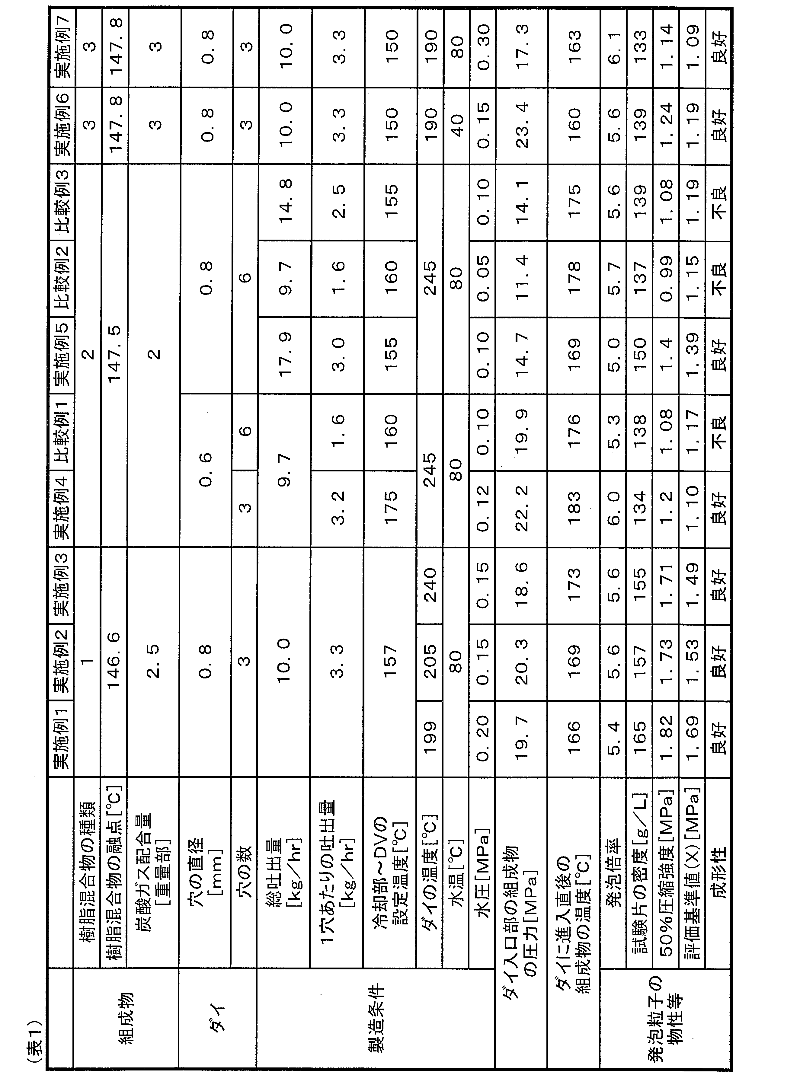
11 フェース面
12 穴
13 樹脂通路
14 ランド部における流路
15 ランド部
a ランド部の長さ
b 穴の直径
Claims (15)
- ダイを備える押出機を用いて、分岐構造を有するポリプロピレン系樹脂を含む樹脂混合物と発泡剤とを含む組成物を溶融混練する溶融混練工程と、
前記押出機よりも低圧かつ液相である領域に、前記ダイを通過させて前記組成物を押出す押出工程と、
前記領域中で前記組成物を細断する細断工程と、
ポリプロピレン系樹脂押出発泡粒子を得る工程と、を有し、
前記発泡剤は炭酸ガスであり、
前記領域の温度は、40℃~90℃であり、
前記ダイの入口部の前記組成物の圧力は、14.5MPa以上であり、
前記ダイの1穴あたりの前記組成物の吐出量は、2.5kg/hrより大きく、かつ、5.0kg/hr以下である、ポリプロピレン系樹脂押出発泡粒子の製造方法。 - 前記ダイに進入直後の前記組成物の温度は、前記樹脂混合物の融点+0℃~当該融点+40℃である、請求項1に記載のポリプロピレン系樹脂押出発泡粒子の製造方法。
- 前記ダイに進入直後の前記組成物の温度は、前記樹脂混合物の融点+10℃~当該融点+40℃である、請求項1に記載のポリプロピレン系樹脂押出発泡粒子の製造方法。
- 前記ダイの温度は、前記樹脂混合物の融点+40℃~当該融点+100℃である、請求項1~3の何れか1項に記載のポリプロピレン系樹脂押出発泡粒子の製造方法。
- 前記ダイの穴の直径は、1.0mm未満である、請求項1~4の何れか1項に記載のポリプロピレン系樹脂押出発泡粒子の製造方法。
- 前記領域の温度は、60℃~90℃である、請求項1~5の何れか1項に記載のポリプロピレン系樹脂押出発泡粒子の製造方法。
- 前記ポリプロピレン系樹脂押出発泡粒子の発泡倍率は、3倍~24倍である、請求項1~6の何れか1項に記載のポリプロピレン系樹脂押出発泡粒子の製造方法。
- 前記分岐構造を有するポリプロピレン系樹脂は、線状ポリプロピレン系樹脂と共役ジエン系化合物とラジカル重合開始剤とを含む混合物を溶融混練して得られる樹脂である、請求項1~7の何れか1項に記載のポリプロピレン系樹脂押出発泡粒子の製造方法。
- 前記分岐構造を有するポリプロピレン系樹脂の200℃、0.1rad/sにおける損失正接tanδは、4以下である、請求項1~8の何れか1項に記載のポリプロピレン系樹脂押出発泡粒子の製造方法。
- 前記分岐構造を有するポリプロピレン系樹脂の230℃におけるMFRは、0.5g/10分~20.0g/10分である、請求項1~9の何れか1項に記載のポリプロピレン系樹脂押出発泡粒子の製造方法。
- 前記分岐構造を有するポリプロピレン系樹脂の200℃における溶融張力は、3cN~20cNである、請求項1~10の何れか1項に記載のポリプロピレン系樹脂押出発泡粒子の製造方法。
- 前記樹脂混合物の融点は、130℃~165℃である、請求項1~11の何れか1項に記載のポリプロピレン系樹脂押出発泡粒子の製造方法。
- 前記発泡剤の使用量は、前記樹脂混合物の重量100.0重量部に対して、0.5重量部~7.0重量部である、請求項1~12の何れか1項に記載のポリプロピレン系樹脂押出発泡粒子の製造方法。
- 請求項1~13のいずれか1項に記載のポリプロピレン系樹脂押出発泡粒子の製造方法により得られたポリプロピレン系樹脂押出発泡粒子を、金型が備える少なくとも2つの型から形成される成形空間内に充填し、当該成形空間内の前記ポリプロピレン系樹脂押出発泡粒子を加熱する加熱工程を有する、ポリプロピレン系樹脂発泡成形体の製造方法。
- 前記ポリプロピレン系樹脂発泡成形体の50%圧縮強度は、下記式(1)に基づいて算出される評価基準値(X)より大きい、請求項14に記載のポリプロピレン系樹脂発泡成形体の製造方法:
前記50%圧縮強度は、ISO 844に準拠し、引張圧縮試験機を用いて、前記ポリプロピレン系樹脂発泡成形体の厚みの10%の速度で前記ポリプロピレン系樹脂発泡成形体を圧縮したときの50%圧縮時の圧縮応力の値であり、
前記式(1)は、
評価基準値(X)[MPa]=(0.0000056×D3+0.062×D2-0.0302×D-20)/1000
であり、
前記式(1)中のDは前記ポリプロピレン系樹脂発泡成形体の密度(g/L)であり、
前記ポリプロピレン系樹脂発泡成形体の前記密度は、前記ポリプロピレン系樹脂発泡成形体の重量W(g)を測定し、測定された重量W(g)を、前記ポリプロピレン系樹脂発泡成形体の体積Vで除すことにより得られた値である。
Priority Applications (2)
| Application Number | Priority Date | Filing Date | Title |
|---|---|---|---|
| EP22780858.1A EP4316764B1 (en) | 2021-03-29 | 2022-03-29 | PROCESS FOR THE PRODUCTION OF EXTRUDED EXPANDED POLYPROPYLENE RESIN PARTICLES |
| JP2023511336A JP7840931B2 (ja) | 2021-03-29 | 2022-03-29 | ポリプロピレン系樹脂押出発泡粒子の製造方法 |
Applications Claiming Priority (2)
| Application Number | Priority Date | Filing Date | Title |
|---|---|---|---|
| JP2021-055924 | 2021-03-29 | ||
| JP2021055924 | 2021-03-29 |
Publications (1)
| Publication Number | Publication Date |
|---|---|
| WO2022210647A1 true WO2022210647A1 (ja) | 2022-10-06 |
Family
ID=83459394
Family Applications (1)
| Application Number | Title | Priority Date | Filing Date |
|---|---|---|---|
| PCT/JP2022/015295 Ceased WO2022210647A1 (ja) | 2021-03-29 | 2022-03-29 | ポリプロピレン系樹脂押出発泡粒子の製造方法 |
Country Status (3)
| Country | Link |
|---|---|
| EP (1) | EP4316764B1 (ja) |
| JP (1) | JP7840931B2 (ja) |
| WO (1) | WO2022210647A1 (ja) |
Cited By (1)
| Publication number | Priority date | Publication date | Assignee | Title |
|---|---|---|---|---|
| CN116589787A (zh) * | 2023-03-24 | 2023-08-15 | 重庆长安汽车股份有限公司 | 发泡聚丙烯板材及其制备方法、轮罩衬板及其制备方法、车辆 |
Citations (5)
| Publication number | Priority date | Publication date | Assignee | Title |
|---|---|---|---|---|
| JPH0711041A (ja) | 1993-06-22 | 1995-01-13 | Sekisui Plastics Co Ltd | 熱可塑性樹脂の予備発泡粒子及びその製造方法 |
| JP2002542360A (ja) | 1999-04-19 | 2002-12-10 | バセル テクノロジー カンパニー ベスローテン フェンノートシャップ | 高い溶融強度を持つ軟質プロピレンポリマーブレンド |
| JP2013010890A (ja) * | 2011-06-30 | 2013-01-17 | Japan Polypropylene Corp | ポリプロピレン系樹脂組成物および発泡シート |
| JP2018059055A (ja) * | 2016-09-30 | 2018-04-12 | 積水化成品工業株式会社 | ポリプロピレン系樹脂、樹脂発泡シート、及び、樹脂発泡成形体 |
| WO2020004429A1 (ja) | 2018-06-28 | 2020-01-02 | 株式会社カネカ | 改質ポリプロピレン樹脂およびその製造方法、並びに、当該改質ポリプロピレン樹脂を用いた押出発泡粒子およびその製造方法 |
Family Cites Families (2)
| Publication number | Priority date | Publication date | Assignee | Title |
|---|---|---|---|---|
| EP3489287B1 (en) * | 2016-07-19 | 2023-01-04 | Kaneka Corporation | Polypropylene-type resin pre-expanded particles, and method for producing said pre-expanded particles |
| JP7059554B2 (ja) | 2017-10-05 | 2022-04-26 | 日本ポリプロ株式会社 | ポリプロピレン系多層発泡シート表層用樹脂組成物 |
-
2022
- 2022-03-29 JP JP2023511336A patent/JP7840931B2/ja active Active
- 2022-03-29 WO PCT/JP2022/015295 patent/WO2022210647A1/ja not_active Ceased
- 2022-03-29 EP EP22780858.1A patent/EP4316764B1/en active Active
Patent Citations (5)
| Publication number | Priority date | Publication date | Assignee | Title |
|---|---|---|---|---|
| JPH0711041A (ja) | 1993-06-22 | 1995-01-13 | Sekisui Plastics Co Ltd | 熱可塑性樹脂の予備発泡粒子及びその製造方法 |
| JP2002542360A (ja) | 1999-04-19 | 2002-12-10 | バセル テクノロジー カンパニー ベスローテン フェンノートシャップ | 高い溶融強度を持つ軟質プロピレンポリマーブレンド |
| JP2013010890A (ja) * | 2011-06-30 | 2013-01-17 | Japan Polypropylene Corp | ポリプロピレン系樹脂組成物および発泡シート |
| JP2018059055A (ja) * | 2016-09-30 | 2018-04-12 | 積水化成品工業株式会社 | ポリプロピレン系樹脂、樹脂発泡シート、及び、樹脂発泡成形体 |
| WO2020004429A1 (ja) | 2018-06-28 | 2020-01-02 | 株式会社カネカ | 改質ポリプロピレン樹脂およびその製造方法、並びに、当該改質ポリプロピレン樹脂を用いた押出発泡粒子およびその製造方法 |
Non-Patent Citations (1)
| Title |
|---|
| See also references of EP4316764A4 |
Cited By (2)
| Publication number | Priority date | Publication date | Assignee | Title |
|---|---|---|---|---|
| CN116589787A (zh) * | 2023-03-24 | 2023-08-15 | 重庆长安汽车股份有限公司 | 发泡聚丙烯板材及其制备方法、轮罩衬板及其制备方法、车辆 |
| CN116589787B (zh) * | 2023-03-24 | 2024-07-26 | 重庆长安汽车股份有限公司 | 发泡聚丙烯板材及其制备方法、轮罩衬板及其制备方法、车辆 |
Also Published As
| Publication number | Publication date |
|---|---|
| EP4316764B1 (en) | 2025-12-31 |
| EP4316764A4 (en) | 2025-03-19 |
| JPWO2022210647A1 (ja) | 2022-10-06 |
| EP4316764A1 (en) | 2024-02-07 |
| JP7840931B2 (ja) | 2026-04-06 |
Similar Documents
| Publication | Publication Date | Title |
|---|---|---|
| US10941265B2 (en) | Polypropylene-type resin pre-expanded particles, and method for producing said pre-expanded particles | |
| JP7671610B2 (ja) | ポリプロピレン系樹脂押出発泡粒子の製造方法 | |
| US8779017B2 (en) | Foam and production method of the same | |
| EP2208751B1 (en) | Pre-expanded polypropylene resin particle, and method for production thereof | |
| JP7857279B2 (ja) | ポリプロピレン系樹脂押出発泡粒子およびその製造方法、並びに発泡成形体 | |
| EP4063441A1 (en) | Polypropylene resin foam particles, method for producing same, and polypropylene resin foam molded article | |
| JP7833419B2 (ja) | 分岐構造を有するポリプロピレン系樹脂の製造方法、押出発泡粒子の製造方法、および、発泡成形体の製造方法 | |
| EP4112678A1 (en) | Polypropylene-based resin foamed particles, method for producing same, and polypropylene-based resin foam molded body | |
| JP7840931B2 (ja) | ポリプロピレン系樹脂押出発泡粒子の製造方法 | |
| WO2022154070A1 (ja) | ポリプロピレン系樹脂押出発泡粒子およびその製造方法、並びに発泡成形体 | |
| JP7832171B2 (ja) | 押出発泡用ポリプロピレン系樹脂組成物、押出発泡粒子および発泡成形体 | |
| WO2023127914A1 (ja) | ポリプロピレン系樹脂押出発泡粒子の製造方法 | |
| JP7809692B2 (ja) | ポリプロピレン系樹脂押出発泡粒子 | |
| JP7789684B2 (ja) | 押出発泡粒子およびその製造方法 | |
| EP4083089A1 (en) | Polypropylene resin composition, method for producing same, method for producing pre-foamed particles, and method for producing foam molded articles | |
| JP7862369B2 (ja) | ポリプロピレン系樹脂押出発泡粒子およびその製造方法、並びに発泡成形体 | |
| WO2023176911A1 (ja) | ポリプロピレン系樹脂押出発泡粒子の製造方法 | |
| WO2022210645A1 (ja) | ポリプロピレン系樹脂押出発泡粒子およびその製造方法、並びに発泡成形体 | |
| WO2023054223A1 (ja) | ポリプロピレン系樹脂押出発泡粒子、ポリプロピレン系樹脂発泡成形体および積層発泡体 | |
| WO2022210648A1 (ja) | ポリプロピレン系樹脂押出発泡粒子の製造方法 | |
| EP4299665A1 (en) | Polypropylene resin extruded foam particles and polypropylene resin foam molded body | |
| JP2024142608A (ja) | 分岐構造を有するポリプロピレン系樹脂の押出発泡粒子の製造方法、および発泡成形体の製造方法 |
Legal Events
| Date | Code | Title | Description |
|---|---|---|---|
| 121 | Ep: the epo has been informed by wipo that ep was designated in this application |
Ref document number: 22780858 Country of ref document: EP Kind code of ref document: A1 |
|
| WWE | Wipo information: entry into national phase |
Ref document number: 2023511336 Country of ref document: JP |
|
| WWE | Wipo information: entry into national phase |
Ref document number: 2022780858 Country of ref document: EP |
|
| NENP | Non-entry into the national phase |
Ref country code: DE |
|
| ENP | Entry into the national phase |
Ref document number: 2022780858 Country of ref document: EP Effective date: 20231030 |
|
| WWG | Wipo information: grant in national office |
Ref document number: 2022780858 Country of ref document: EP |