WO2022210656A1 - 止血器具 - Google Patents
止血器具 Download PDFInfo
- Publication number
- WO2022210656A1 WO2022210656A1 PCT/JP2022/015311 JP2022015311W WO2022210656A1 WO 2022210656 A1 WO2022210656 A1 WO 2022210656A1 JP 2022015311 W JP2022015311 W JP 2022015311W WO 2022210656 A1 WO2022210656 A1 WO 2022210656A1
- Authority
- WO
- WIPO (PCT)
- Prior art keywords
- support member
- patient
- hemostatic device
- puncture site
- band
- Prior art date
- Legal status (The legal status is an assumption and is not a legal conclusion. Google has not performed a legal analysis and makes no representation as to the accuracy of the status listed.)
- Ceased
Links
Images












Classifications
-
- A—HUMAN NECESSITIES
- A61—MEDICAL OR VETERINARY SCIENCE; HYGIENE
- A61B—DIAGNOSIS; SURGERY; IDENTIFICATION
- A61B17/00—Surgical instruments, devices or methods
- A61B17/12—Surgical instruments, devices or methods for ligaturing or otherwise compressing tubular parts of the body, e.g. blood vessels or umbilical cord
- A61B17/132—Tourniquets
- A61B17/135—Tourniquets inflatable
-
- A—HUMAN NECESSITIES
- A61—MEDICAL OR VETERINARY SCIENCE; HYGIENE
- A61B—DIAGNOSIS; SURGERY; IDENTIFICATION
- A61B17/00—Surgical instruments, devices or methods
- A61B17/12—Surgical instruments, devices or methods for ligaturing or otherwise compressing tubular parts of the body, e.g. blood vessels or umbilical cord
- A61B17/132—Tourniquets
- A61B17/1322—Tourniquets comprising a flexible encircling member
- A61B17/1325—Tourniquets comprising a flexible encircling member with means for applying local pressure
-
- A—HUMAN NECESSITIES
- A61—MEDICAL OR VETERINARY SCIENCE; HYGIENE
- A61B—DIAGNOSIS; SURGERY; IDENTIFICATION
- A61B17/00—Surgical instruments, devices or methods
- A61B17/0057—Implements for plugging an opening in the wall of a hollow or tubular organ, e.g. for sealing a vessel puncture or closing a cardiac septal defect
- A61B2017/00646—Type of implements
- A61B2017/00659—Type of implements located only on one side of the opening
-
- A—HUMAN NECESSITIES
- A61—MEDICAL OR VETERINARY SCIENCE; HYGIENE
- A61B—DIAGNOSIS; SURGERY; IDENTIFICATION
- A61B17/00—Surgical instruments, devices or methods
- A61B2017/00831—Material properties
- A61B2017/00902—Material properties transparent or translucent
-
- A—HUMAN NECESSITIES
- A61—MEDICAL OR VETERINARY SCIENCE; HYGIENE
- A61B—DIAGNOSIS; SURGERY; IDENTIFICATION
- A61B17/00—Surgical instruments, devices or methods
- A61B17/12—Surgical instruments, devices or methods for ligaturing or otherwise compressing tubular parts of the body, e.g. blood vessels or umbilical cord
- A61B2017/12004—Surgical instruments, devices or methods for ligaturing or otherwise compressing tubular parts of the body, e.g. blood vessels or umbilical cord for haemostasis, for prevention of bleeding
-
- A—HUMAN NECESSITIES
- A61—MEDICAL OR VETERINARY SCIENCE; HYGIENE
- A61B—DIAGNOSIS; SURGERY; IDENTIFICATION
- A61B90/00—Instruments, implements or accessories specially adapted for surgery or diagnosis and not covered by any of the groups A61B1/00 - A61B50/00, e.g. for luxation treatment or for protecting wound edges
- A61B90/08—Accessories or related features not otherwise provided for
- A61B2090/0807—Indication means
-
- A—HUMAN NECESSITIES
- A61—MEDICAL OR VETERINARY SCIENCE; HYGIENE
- A61B—DIAGNOSIS; SURGERY; IDENTIFICATION
- A61B90/00—Instruments, implements or accessories specially adapted for surgery or diagnosis and not covered by any of the groups A61B1/00 - A61B50/00, e.g. for luxation treatment or for protecting wound edges
- A61B90/39—Markers, e.g. radio-opaque or breast lesions markers
- A61B2090/3937—Visible markers
Definitions
- the present invention relates to a hemostatic device.
- various medical elongate bodies are introduced into the blood vessel through the puncture site formed by puncturing the blood vessel of the patient's limb such as arm or hand, and treatment and treatment of the lesion site are performed.
- the procedure to do is known.
- U.S. Pat. No. 6,200,009 discloses a hemostatic device for hemostasis at a puncture site formed to allow access to blood vessels running through the hand (including the distal radial artery).
- the hemostatic device of Patent Document 1 includes a pressing member that applies pressure to a puncture site formed in a patient's hand (hereinafter also simply referred to as "puncture site"), and a fixing member for fixing the pressing member to the patient's hand.
- the strap includes a first strap to be placed between the patient's fingers and a second strap to be wrapped around the forearm side of the patient's hand.
- an operator When forming the puncture site on the hand, an operator such as a doctor (hereinafter referred to as the "operator") must place the puncture site at a predetermined position avoiding the metacarpal bone of the index finger and the metacarpal bone of the thumb of the hand. may be set. By setting the puncture site at such a predetermined position, the operator can prevent the puncture device such as the indwelling needle from interfering with the metacarpal bone of each finger when forming the puncture site.
- a doctor hereinafter referred to as the "operator”
- the operator arranges the pressing member and the support member of the hemostatic device of Patent Document 1 so as to overlap the puncture site.
- the support member may be placed on the metacarpal bone of the index finger and the metacarpal bone of the thumb.
- the hemostatic device of Patent Document 1 when the second belt member is wrapped around the patient's hand while the supporting member is placed on the patient's hand as described above, a gap is created between the pressing member and the hand. , the second strap does not fit around the circumference of the patient's hand.
- the pressure member and the support member can be firmly fixed to the patient's hand by strongly tightening the first band of the hemostatic device of Patent Document 1.
- the first band of the hemostatic device of Patent Document 1 needs to be tightly tightened, which may cause pain to the patient. Therefore, in the hemostatic device of Patent Document 1, when the first strap cannot be strongly tightened due to patient pain or the like, the supporting member approaches the body surface of the hand from the fingertip side of the hand toward the forearm side. It is arranged in a state inclined to the direction.
- the hemostatic device of Patent Document 1 when the support member is arranged as described above, the pressing member cannot apply pressure force to the puncture site in the vertical direction. As a result, the hemostatic device of Patent Document 1 cannot effectively apply pressure to the puncture site.
- the present invention provides an effective method for stopping bleeding at a puncture site formed at a predetermined position avoiding the metacarpal bone of the index finger and the metacarpal bone of the thumb of the hand.
- An object of the present invention is to provide a hemostatic device capable of applying pressure.
- a hemostatic device comprises: a support member configured to cover a puncture site formed in a patient; a fixing member configured to fix the support member to the puncture site of the patient; a pressing member connected to a member and configured to press against the puncture site of the patient, the support member located distally of the pressing member and forming an end of the support member. a lower end located on the base end side of the pressing member and forming an end opposite to the upper end; and a side surface connecting the upper end and the lower end, wherein the Having a greater stiffness than the pressing member, the securing member is configured for placement between the patient's fingers and includes a first band extending in a first direction and a second band extending in a second direction different from the first direction.
- the support member has a width that decreases from the upper end portion toward the lower end portion, and a thickness of the side portion that decreases toward the upper end portion.
- the first band extends in the first direction from the upper end, and the second band extends from the side of the side surface. side in the second direction.
- the above hemostatic instrument has a support member with greater rigidity than the pressing member.
- the support member is arranged to cover the puncture site together with the pressing member when stopping bleeding at the puncture site formed at a predetermined position avoiding the metacarpal bone of the index finger of the patient's hand and the metacarpal bone of the thumb of the patient's hand. be done.
- the support member can prevent the pressing member from rising from the patient's hand by pressing the pressing member against the patient's hand.
- the width of the support member is reduced from the upper end to the lower end. Therefore, when the support member is placed in the patient's hand, the support member can be placed along the metacarpal bone of the index finger and the metacarpal bone of the thumb.
- the above-described hemostatic device can tightly wrap the second strap portion around the patient's hand.
- the thickness of the side surface portion of the supporting member decreases from the upper end portion toward the lower end portion.
- a first strap configured to be positioned between the patient's fingers extends from the top side of the support member and is configured to press the top side of the support member against the patient's hand. be done. Therefore, the pressing member can apply force to one end of the support member when starting to stop bleeding with the hemostatic device attached to the patient's hand. One end side of the support member is lifted by the force applied by the pressing member. The support member is thereby arranged such that the lower surface of the support member is substantially parallel to the body surface of the patient's hand.
- the pressing force of the pressing member is applied to the puncture site by fixing the first strap portion and the second strap portion to the patient's hand while the pressing member and the support member are arranged at the puncture site.
- the hemostatic device can effectively apply pressure to the puncture site.
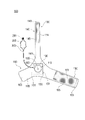
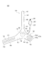
- FIG. 3 is a diagram showing the hemostatic device according to the first embodiment, and is a plan view seen from the outer surface side of each band.
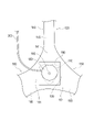
- FIG. 3 is a diagram showing the hemostatic device according to the first embodiment, and is a plan view seen from the inner surface side of each band. It is a figure which expands and shows a part of hemostatic instrument seen from the outer surface side of each band part. It is a figure which expands and shows a part of hemostatic instrument seen from the inner surface side of each band part.
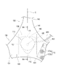
- FIG. 4 is an enlarged plan view showing a part of the hemostatic device seen from the outer surface side of each band.
- FIG. 6A is a partial cross-sectional view of the hemostatic device taken along arrows 6A-6A shown in FIG.
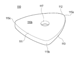
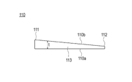
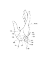
- FIG. 9A is a side view of the support member according to the first embodiment viewed from the direction of arrow 9A in FIG. 8; 1 is a view showing a patient's hand (right hand) to be used with the hemostatic device according to the first embodiment; FIG. It is a figure which shows simply the 1st usage example of the hemostatic instrument which concerns on 1st Embodiment. It is a figure which shows simply the 1st usage example of the hemostatic instrument which concerns on 1st Embodiment.
- FIG. 14A is a partial cross-sectional view taken along arrows 14A-14A shown in FIG. 13;
- FIG. FIG. 4 is a diagram schematically showing a second usage example of the hemostatic device according to the first embodiment;
- FIG. 11 is a diagram schematically showing a third usage example of the hemostatic device according to the first embodiment;
- FIG. 10 is a diagram schematically showing a fourth usage example of the hemostatic device according to the first embodiment;
- FIG. 10 is a diagram showing a hemostatic device according to a modification of the first embodiment, and is a plan view seen from the outer surface side of each band.
- FIG. 10 is a view showing the hemostatic device according to the second embodiment, and is a plan view seen from the outer surface side of each band. It is a figure which shows the modification of a support member. It is a figure which shows the modification regarding the shape of a support member. It is a figure which shows the modification regarding the shape of a support member. It is a figure which shows the modification regarding the shape of a support member. It is a figure which shows the modification regarding the shape of a support member. It is a figure which shows the modification regarding the shape of a support member.
- FIGS. 10 to 17 are diagrams for explaining examples of use and effects of the hemostatic device 100.
- FIG. 10 to 17 are diagrams for explaining examples of use and effects of the hemostatic device 100.
- the hemostatic device 100 is, for example, as shown in FIGS. 10 and 13 to 17, a puncture site (for example, a puncture site described later) formed in a hand H located distally (fingertip side) relative to the patient's forearm A.
- a puncture site for example, a puncture site described later
- a hand H located distally (fingertip side) relative to the patient's forearm A.
- the specific position of the puncture site to be stopped by the hemostatic device 100 is not particularly limited. is exemplified.
- the first puncture site p1 is, as shown in FIGS. 10, 13 and 14, the snuff box of the palmar artery running on the dorsal side of the right hand H1 (hand H) located distal to the forearm A of the patient.
- This is a puncture site formed in the distal radial artery (hereinafter, also referred to as "blood vessel V1") positioned distally of the V1.
- the first puncture site p1 is located between the positions of the metacarpal bone B1 of the index finger and the metacarpal bone B2 of the thumb, at a predetermined position avoiding the metacarpal bone B1 of the index finger and the metacarpal bone B2 of the thumb.
- the snuff box is a cavity in the hand located near the radius when the patient spreads the thumb of the hand H.
- the second puncture site p2 is, as shown in FIGS. 10 and 15, a puncture site formed in the artery V2 located in the snuff box of the palmar artery running on the dorsal side of the right hand H1.
- the second puncture site p2 is positioned closer to the patient's forearm A side than the first puncture site p1, and is located between the extensor pollicis longus tendon T1 and the extensor pollicis brevis tendon T2 located on the back of the patient's right hand H1. located in between.
- the second puncture site p2 is located at a predetermined position avoiding the metacarpal bone B1 of the index finger and the metacarpal bone B2 of the thumb.
- the third puncture site p3 is a puncture site formed in the patient's left hand H2 (hand H) at a position corresponding to the first puncture site p1 illustrated in the patient's right hand H1.
- the fourth puncture site p4 is a puncture site formed in the patient's left hand H2 (hand H) at a position corresponding to the second puncture site p2 illustrated in the patient's right hand H1.
- first puncture site p1 formed on the patient's right hand H1 is simply referred to as the "first puncture site p1”
- second puncture site p2 formed on the patient's right hand H1 is simply referred to as the "second puncture site p1”. It is also described as “puncture site p2”.
- third puncture site p3 formed on the patient's left hand H2 is simply referred to as “third puncture site p3”
- fourth puncture site p4 formed on the patient's left hand H2 is simply referred to as "fourth puncture site p4". Also described.
- the hemostatic device 100 will be described in detail below.
- the hemostatic device 100 includes a support member 110 configured to cover the first puncture site p1, and the support member 110 covering the first puncture site p1. and a pressing member 180 connected to the support member 110 and configured to press against the first puncture site.
- the above “connected to the support member 110 ” includes that the pressing member 180 is indirectly connected to the support member 110 .
- connecting the pressing member 180 (expanding member 180) to the supporting member 110 via the connecting member 190 as shown in FIGS. “include.
- the pressing member 180 may be an expandable member such as a balloon having a lumen 183 through which fluid such as air can flow.
- an expansion member in the following description, an example in which the pressing member 180 is configured by an expansion member will be described.
- the expansion member 180 is composed of, for example, a sheet of membrane-like member formed in a bag shape so as to have a lumen 183 .
- the expansion member 180 is formed by joining the edges of two sheet-like membrane materials formed in a substantially rectangular shape with a lumen 183 formed between the two sheet-like membrane materials.
- the expansion member 180 expands when fluid such as air is supplied to the lumen 183 and contracts when the fluid supplied to the lumen 183 is discharged.
- FIG. 6 shows a cross-sectional view of expansion member 180 when fluid is supplied to expansion member 180 and expansion member 180 is expanded.
- the film material forming the expansion member 180 can be made of, for example, a resin material having a predetermined thickness.
- a tube 203 (see FIGS. 1 and 2), which will be described later, is connected to the lumen 183 of the expansion member 180 .
- the material of the film-like member constituting the expansion member 180 is not particularly limited, but examples include polyvinyl chloride, polyethylene, polypropylene, polybutadiene, polyolefin such as ethylene-vinyl acetate copolymer (EVA), polyethylene terephthalate (PET ), polyester such as polybutylene terephthalate (PBT), polyvinylidene chloride, silicone, polyurethane, polyamide elastomer, polyurethane elastomer, various thermoplastic elastomers such as polyester elastomer, nylon, nylon elastomer, or any combination thereof (blend resins, polymer alloys, laminates, etc.) can be used.
- polyvinyl chloride polyethylene, polypropylene, polybutadiene
- polyolefin such as ethylene-vinyl acetate copolymer (EVA), polyethylene terephthalate (PET ), polyester such as polybutylene terephthalate (PBT
- the expansion member 180 is arranged on the inner surface 130a side of the covering portion 130 of the fixing member 120, as shown in FIG.
- the inner surface 130a of the covering portion 130 is a surface that is arranged on the body surface side of the patient's right hand H1 when the hemostatic device 100 is attached to the patient's right hand H1 (see FIG. 14). Also, the outer surface 130b of the covering portion 130 is a surface located on the opposite side of the inner surface 130a.
- a connecting member 190 is arranged on the inner surface 130a of the covering portion 130.
- Extension member 180 can be connected to support member 110 via connecting member 190 .
- the peripheral edge of extension member 180 can be connected to connecting member 190 by, for example, an adhesive or a fusion bond.
- connection member 190 is arranged so as to form a space 191 between itself and the cover 130 .
- a support member 110 is arranged in the space 191 .
- connection member 190 can be configured by a member made of resin, for example.
- the outer periphery of the connecting member 190 can be connected to the covering portion 130 by, for example, an adhesive or fusion.
- the expansion member 180 has a circular shape in a plan view shown in FIGS. 1 to 5.
- the shape of the expansion member 180 in plan view is not limited to a circle.
- the expansion member 180 is provided with a marker portion 185 for aligning the expansion member 180 with the first puncture site p1.
- the marker part 185 is arranged on the outer surface of the expansion member 180 as shown in FIG. Note that the marker portion 185 may be arranged on the inner surface of the expansion member 180 facing the lumen 183 .
- the marker portion 185 can be formed of, for example, a rectangular marker in which the entire marker portion 185 is colored.
- the specific shape, color, forming method, and position of the marker portion 185 on the expansion member 180 are not particularly limited.
- the marker portion 185 may be composed of a transparent center portion and a colored linear frame portion surrounding the center portion.
- the support member 110 is positioned distally of the extension member 180 and forms an end of the support member 110; 180 and has a lower end portion 112 forming an end portion opposite to the upper end portion 111 and a side portion 113 connecting the upper end portion 111 and the lower end portion 112 .
- the distal end side of the expansion member 180 means the end side (the upper side in FIGS. 5 and 13) of the expansion member 180 arranged on the patient's fingertip side when the hemostatic device 100 is attached to the patient's right hand H1.
- the "base end side of the expansion member 180” is the end portion side of the expansion member 180 arranged on the forearm A side of the patient when the hemostatic device 100 is attached to the patient's right hand H1 (bottom side of FIGS. 5 and 13). side).
- the support member 110 is configured such that the width W of the support member 110 becomes shorter from the upper end portion 111 toward the lower end portion 112, as shown in FIG.
- the support member 110 is configured such that the thickness of the side surface portion 113 decreases from the upper end portion 111 toward the lower end portion 112, as shown in FIG. 6 and 9, the upper surface 110b of the support member 110 is inclined from the upper end portion 111 toward the lower end portion 112 toward the lower surface 110a.
- the lower surface 110a is the surface on which the expansion member 180 is arranged
- the upper surface 110b is the surface on which the covering portion 130 is arranged.
- the support member 110 has a symmetrical shape with respect to the long axis (the axis along the extending direction) C of the first band portion 140 .
- the support member 110 has a substantially triangular planar shape.
- Each corner 115a, 115b, 115c located on the outer peripheral side of the support member 110 has a rounded shape.
- the support member 110 has holes 117 penetrating through the support member 110 in the thickness direction.
- the hole 117 can be positioned to overlap the expansion member 180, as shown in FIG.
- the hole portion 117 is arranged at a position overlapping the marker portion 185 arranged on the expansion member 180 .
- the portion of the expansion member 180 provided with the marker portion 185, the portion of the connecting member 190 that overlaps the marker portion 185, and the portion of the covering portion 130 that overlaps the marker portion 185 can be transparent.
- the members 130, 180, and 190 are configured in this manner, the operator attaches the hemostatic device 100 to the patient's right hand H1 as shown in FIGS.
- transparent portions of members 130, 180, and 190 the position of marker portion 185 arranged on expansion member 180 and/or first puncture site p1 can be easily visually confirmed.
- transparent includes colored transparent, colorless transparent, and translucent.
- the support member 110 can be composed of a member having greater rigidity than the expansion member 180. With such a configuration, the support member 110 is expanded against the patient's right hand H1 when the expansion member 180 applies pressure to the first puncture site p1 as shown in FIG. Member 180 can be held down. Thereby, it is possible to prevent the expansion member 180 from rising from the patient's right hand H1.
- examples of the constituent material of the support member 110 include acrylic resin, polyvinyl chloride (particularly hard polyvinyl chloride), polyolefins such as polyethylene, polypropylene, and polybutadiene, polystyrene, Poly-(4-methylpentene-1), polycarbonate, ABS resin, polymethyl methacrylate (PMMA), polyacetal, polyacrylate, polyacrylonitrile, polyvinylidene fluoride, ionomer, acrylonitrile-butadiene-styrene copolymer, polyethylene terephthalate (PET ) etc. can be used.
- ⁇ Fixing member> The fixing member 120, as shown in FIGS. 160 and .
- the covering part 130 constitutes a body part to which the band parts 140, 150, 160 are connected. As shown in FIGS. 5 and 6, the support member 110, the expansion member 180, and the connection member 190 are arranged on the covering portion 130. As shown in FIGS. 5 and 6, the support member 110, the expansion member 180, and the connection member 190 are arranged on the covering portion 130. As shown in FIGS. 5 and 6, the support member 110, the expansion member 180, and the connection member 190 are arranged on the covering portion 130. As shown in FIGS.
- the fixing member 120 may be configured such that the covering portion 130 and the band portions 140, 150, and 160 are integrally formed, or the band portions 140, 150, and 160 are formed in the member that constitutes the covering portion 130. A member may be connected. Alternatively, the fixing member 120 may have the band members 140 , 150 , 160 directly connected to the supporting member 110 without the covering member 130 .
- the first band 140 is configured to be placed between the patient's fingers.
- the first strap portion 140 extends in a predetermined first direction.
- the first band portion 140 includes one end portion 141 located on the support member 110 side, the other end portion 143 located on the opposite side of the one end portion 141, and the one end portion 141 and the other end portion 141. a body portion 145 extending between the ends 143 .
- the first strap part 140 is placed on the inter-finger part fb between the thumb and forefinger of the patient's right hand H1 with the expansion member 180 arranged at the first puncture site p1.
- the second band portion 150 extends in a second direction different from the first direction in which the first band portion 140 extends. Specifically, as shown in FIG. 5, the second band portion 150 extends from one side (the left side in FIG. 5) of the side portion 113 of the support member 110. As shown in FIG.
- the second band portion 150 includes one end portion 151 located on the support member 110 side, the other end portion 153 located on the side opposite to the one end portion 151, and the one end portion 151 and the other end portion 151. a body portion 155 extending between the ends 153 .
- the third band portion 160 extends in a third direction different from each of the first direction in which the first band portion 140 extends and the second direction in which the second band portion 150 extends. exist. Specifically, as shown in FIG. 5, the third strap portion 160 is positioned on the other side of the side surface portion 113 located on the opposite side of the second strap portion 150 across the support member 110 (the right side in FIG. 5). extends from
- the third band portion 160 includes one end portion 161 located on the support member 110 side, the other end portion 163 located on the opposite side of the one end portion 161, and the one end portion 161 and the other end portion 161. and a body portion 165 extending between the ends 163 .
- the second strap portion 150 and the third strap portion 160 are wound along the outer periphery of the patient's right hand H1 when the hemostatic device 100 is attached to the patient's right hand H1. can be placed in
- each band 140, 150, 160 is not particularly limited, but can be made of, for example, vinyl chloride resin, polyurethane resin, polyester resin, or the like. Moreover, there are no particular restrictions on the shape, length, thickness, etc. of each of the band portions 140, 150, and 160. FIG.
- the fixing member 120 includes a first fixing portion 171, a second fixing portion 172, and a third fixing portion 171, a second fixing portion 172, and a third fixing portion which enable each of the strap portions 140, 150, and 160 to be fixed to the patient's right hand H1. 173 and a fourth fixing portion 174 .
- a first fixing portion 171 is arranged on the outer surface of the body portion 155 of the second band portion 150 .
- a second fixing portion 172 is arranged on the outer surface of the body portion 165 of the third belt portion 160 .
- a third fixing portion 173 is arranged on the inner surface of the body portion 155 of the second belt portion 150 .
- a fourth fixing portion 174 is arranged on the inner surface of the main body portion 145 of the first band portion 140 .
- the first fixing part 171 and the second fixing part 172 are composed of the male side of the hook-and-loop fastener.
- the third fixing portion 173 and the fourth fixing portion 174 are formed on the female side of the hook-and-loop fastener.
- the hook-and-loop fastener in this specification is a fastener that can be attached and detached on the surface, such as Magic Tape (registered trademark) and Velcro (registered trademark).
- the main body part 155 of the second band part 150 and the main body part 165 of the third band part 160 are configured to be detachable via the third fixing part 173 and the second fixing part 172 . Also, the body portion 145 of the first band portion 140 and the body portion 145 of the second band portion 150 are configured to be detachable via the first fixing portion 171 and the fourth fixing portion 174 .
- the second fixing portion 172 arranged on the main body portion 165 of the third strap portion 160 has an end located on the side of the other end portion 163 of the third strap portion 160 that is the first branch portion. 172a and a plurality of second branch portions 172b. Each of the branched portions 172a and 172b extends substantially linearly from the starting point of the branch formed on the one end portion 161 side of the third band portion 160 toward the other end portion 163 side.
- the fixing parts 171, 172, 173, and 174 are formed by connecting the band parts 140, 150, and 160 with the hemostatic device 100 placed on the patient's right hand H1, thereby forming the supporting member 110 and the expanding member 180. is not limited as long as it can be fixed to the patient's right hand H1. For example, it is possible to arbitrarily omit the installation of some fixing parts, change the positions of the fixing parts in each of the belt parts 140, 150, and 160, or the like. Moreover, when each fixed part 171, 172, 173, 174 is configured by a hook-and-loop fastener, the configuration may be such that the male side and the female side of the hook-and-loop fastener are interchanged.
- each fixing part 171, 172, 173, 174 includes, for example, a snap, a button, a clip, a frame formed with a hole or a protrusion, and an engaging member formed with a hole engageable with the frame.
- a connecting mechanism or the like having a joint portion may be used.
- the hemostatic device 100 has an injection section 201 for injecting fluid into the expansion member 180, as shown in FIGS.
- the injection part 201 is composed of a connector incorporating a check valve (not shown).
- a syringe (not shown) can be connected to the injection part 201 .
- a cushioning member 202 having an expandable space is arranged between the injection part 201 and the expansion member 180 .
- the cushioning member 202 is composed of a flexible bag-like member having a space formed therein.
- An arrow-shaped marker indicating the insertion direction of the syringe into the injection portion 201 may be provided on the cushioning member 202 .
- the injection part 201 is connected to one end of the cushioning member 202 .
- the lumen of injection section 201 communicates with the space of cushioning member 202 .
- the check valve incorporated in injection section 201 is closed, communication between the lumen of injection section 201 and the space of cushioning member 202 is blocked.
- a flexible tube 203 is connected to the other end of the cushioning member 202 .
- the lumen of tube 203 communicates with the space of cushioning member 202 .
- the tube 203 has one end connected to the buffer member 202 and the other end opposite to that connected to the expansion member 180 .
- the lumen of tube 203 communicates with lumen 183 of expansion member 180 .
- the operator When expanding the expansion member 180, the operator inserts the tip tube of a syringe (not shown) into the injection section 201 to open the check valve.
- the operator injects the air in the syringe into the lumen 183 of the expansion member 180 by pushing the plunger of the syringe while the check valve of the injection section 201 is open.
- expansion member 180 When air is injected into the lumen 183 of the expansion member 180, the expansion member 180 expands. As expansion member 180 expands, cushioning member 202 , which communicates with lumen 183 of expansion member 180 via tube 203 , expands. By visually confirming the expansion of the cushioning member 202, the operator can easily grasp that the expansion member 180 has expanded without air leakage.
- the operator When contracting the expanding member 180, the operator inserts the tip tube portion of the syringe into the injection portion 201 and pulls the plunger of the syringe. The operator can discharge the air in the lumen 183 of the expansion member 180 into the syringe by performing the above operation.
- the injection part 201, the buffer member 202, and the tube 203 may be prepared and provided in a state of being connected with the expansion member 180, or may be prepared and provided in a state of being separated from the expansion member 180. You may do so.
- FIG. 11 shows a state after performing various procedures using the sheath tube of the introducer 300 inserted into the first puncture site p1.
- the operator When attaching the hemostatic device 100 to the patient's right hand H1, the operator arranges the expansion member 180 and the support member 110 so as to overlap the first puncture site p1, as shown in FIG. At this time, the operator visually confirms the position of the marker portion 185 arranged on the expansion member 180 through the hole portion 117 (see FIG. 7) formed in the support member 110, and moves the marker portion 185.
- the expansion member 180 and the support member 110 can be appropriately positioned at the first puncture site p1.
- the operator arranges the support member 110 so that the support member 110 overlaps the metacarpal bone B1 of the index finger and the metacarpal bone B2 of the thumb.
- the distance between the metacarpal bone B1 of the index finger and the metacarpal bone B2 of the thumb gradually narrows from the fingertip side toward the forearm A side.
- the width W of the support member 110 decreases from the upper end portion 111 side toward the lower end portion 112 (see FIG. 8). Therefore, the operator can place the support member 110 along the metacarpal bone B1 of the index finger and the metacarpal bone B2 of the thumb.
- the operator can prevent the formation of a gap between the expansion member 180 and the right hand H1 by placing the support member 110 along the metacarpal bone B1 of the index finger and the metacarpal bone B2 of the thumb. .
- the operator wraps the second strap part 150 and the third strap part 160 along the outer periphery of the patient's right hand H1.
- the operator attaches the second fixing portion 172 (see FIG. 1) arranged on the outer surface of the third strap portion 160 to the third fixing portion 173 (see FIG. 2) arranged on the inner surface of the second strap portion 150. ), it is possible to connect the second band 150 and the third band 160 via the fixing portions 172 and 173 .
- the operator connects the belt parts 150 and 160 in a state in which the support member 110 is overlapped with the metacarpal bone B1 of the index finger and the metacarpal bone B2 of the thumb, thereby connecting the belt parts 150 and 160 to the right hand H1. can be tightly wrapped around the perimeter of the
- the operator can connect the third fixing part 173 arranged on the inner surface of the second strap part 150 to the second branch part 172b of the second fixing part 172 when stopping the bleeding at the first puncture site p1.
- the first puncture site p1 is positioned closer to the fingertips of the patient's right hand H1 than the second puncture site p2 (see FIG. 10). Therefore, when the operator stops bleeding at the first puncture site p1, the operator connects the second band 150 with the second band 150 via the second branch 172b located closer to the forearm A of the right hand H1 of the patient than the first branch 172a.
- the third strap part 160 By connecting the third strap part 160, the range in which each strap part 150, 160 restrains the patient's right hand H1 can be narrowed.
- the second fixing portion 172 is arranged on the main body portion 165 of the third band portion 160 . Therefore, a portion of the body portion 165 exists between the second fixing portion 172 and the one end portion 161 of the third band portion 160 .
- the operator winds the third strap part 160 around the patient's right hand H1
- the operator pulls the main body part 165 with one end 161 of the third strap part 160 as a base point, so that the second strap part 150 and the third strap part 150 are pulled together.
- the first branch portion 172a which is not used for connecting the belt portion 160, from floating up from the patient's right hand H1.
- the first branch portion 172a can be prevented from being lifted. (See Figures 15 and 17).
- the third belt body portion 160 itself is divided into a plurality of portions without providing the first branch portion 172a and the second branch portion 172b in the second fixing portion 172 (FIG. 19).
- the third band body part 160 is split at one end 161 located on the covering part 130 side, when the operator wraps the third band body part 160 around the patient's right hand H1, the covering part The second strap portion 150 cannot hold down the entire range (side) to which the strap portion 160 is connected. Therefore, the adhesion of the covering portion 130 and the third strap portion 160 to the right hand H1 is lowered.
- the third band body part 160 when the third band body part 160 is divided, the part of the third band body part 160 that is not connected to the second band body part 150 hangs down from the hemostatic device 100 while the hemostatic device 100 is being used. placed. Therefore, the third strap portion 160 becomes an obstacle when the hemostatic device 100 is attached.
- the width of the third band portion 160 when the third band portion 160 is divided, the width of the third band portion 160 must be increased. As a result, it becomes difficult to form the widths of the second strap portion 150 and the third strap portion 160 to be substantially the same. Further, as a result, when the hemostatic device 100 is attached to the patient's right hand H1, it is difficult to evenly apply force to the position where the second band 150 and the third band 160 are wound. Become.
- the operator passes the first band 140 through the inter-finger portion fb of the patient's right hand H1 located between the thumb and the forefinger, and pulls part of the first band 140 onto the patient's right hand H1. is placed on the palm side of the right hand H1.
- the operator attaches the first fixing portion 171 (see FIG. 1) arranged on the outer surface of the second strap portion 150 to the fourth fixing portion 174 (see FIG. 1) arranged on the inner surface of the first strap portion 140. 2) can connect the first strap portion 140 and the second strap portion 150 via the respective fixing portions 172,174.
- the support member 110 has a substantially triangular shape with three sides. Hemostasis device 100 has three strips 140 , 150 , 160 arranged to extend from each side of support member 110 . Therefore, in the hemostatic device 100, the band members 140, 150, and 160 are connected to each other, so that the support member 110 is placed on the right hand H1 of the patient in a state in which an equal force is applied to each side of the support member 110. can be fixed.
- the support member 110 has a symmetrical shape with respect to the long axis C of the first band portion 140 . Therefore, the hemostatic device 100 is configured by wrapping the band members 150 and 160 extending in the left-right direction with respect to the first band member 140 around the right hand H1 of the patient, thereby applying force to the support member 110 along the left-right direction. can be given equally. Accordingly, the hemostatic device 100 can prevent the support member 110 from being displaced when the support member 110 is placed on the patient's right hand H1.
- the operator expands the expansion member 180 by injecting air into the expansion member 180 with the syringe connected to the injection part 201 .
- the expansion member 180 applies pressure to the first puncture site p1.
- the support member 110 presses the expansion member 180 against the patient's right hand H1.
- the hemostatic device 100 can prevent the expansion member 180 from rising from the patient's right hand H1.
- the operator tightens the first strap portion 140 arranged between the fingers fb more strongly in order to increase the fixing force of the support member 110 to the patient's right hand H1. be able to.
- the operator can place the support member 110 on the patient's right hand H1 even if the support member 110 is placed in an unstable state on the patient's right hand H1. It can be fixed firmly.
- the first belt body part 140 is strongly tightened as described above, the patient may experience pain.
- the hemostatic device 100 is arranged such that the lower surface 110a of the support member 110 is inclined with respect to the body surface of the patient's right hand H1. I can put it away.
- the hemostatic device 100 is configured such that the thickness of the side surface portion 113 of the support member 110 decreases from the upper end portion 111 toward the lower end portion 112 .
- the first strap portion 140 configured to be placed between the patient's fingers between the fingers fb extends from the upper end portion 111 side of the support member 110 and extends from the upper end portion of the support member 110 .
- the part 111 side is configured to be pressed against the right hand F of the patient. Therefore, when the expansion member 180 starts expanding with the hemostatic device 100 attached to the right hand H1 of the patient, the expansion member 180 applies force to the upper end portion 111 of the support member 110 .
- the upper end portion 111 of the support member 110 is lifted by the force applied by the extension member 180 .
- the support member 110 is arranged so that the lower surface 110a of the support member 110 is substantially parallel to the body surface of the patient's right hand H1. Therefore, the hemostatic device 100 can apply pressure force to the first puncture site p1 in the vertical direction when the expansion member 180 is expanded.
- the support member 110 has rounded corners 115a, 115b, and 115c (see FIG. 8). Therefore, the hemostatic device 100 can prevent the corners 115a, 115b, and 115c of the support member 110 from digging into the patient's right hand H1 when the expansion member 180 is expanded to apply pressure to the puncture site p1.
- the operator can use the hemostatic device 100 to stop bleeding at the first puncture site p1 formed in the patient's right hand H1 by the above procedure.
- FIG. 15 shows a second usage example of the hemostatic device 100.
- FIG. A second usage example is a method of stopping bleeding at the second puncture site p2 (see FIG. 10) using the hemostatic device 100 .
- the operator places the inner surface of the second strap portion 150 on the first branch portion 172a (see FIG. 1) of the second fixing portion 172 placed on the outer surface of the third strap portion 160.
- the second strap part 150 and the third strap part 160 can be connected via the respective fixing parts 172, 173 by bringing the third fixing part 173 (see FIG. 2) into contact.
- the operator When stopping bleeding at the second puncture site p2, the operator holds the second band 150 and the third band 160 through the first branch 172a located closer to the patient's fingertip than the first branch 172a. By connecting them, the range in which the right hand H1 of the patient is restrained by each strap 150, 160 can be narrowed.
- FIG. 16 shows a third usage example of the hemostatic device 100.
- a third usage example is a method of using the hemostatic device 100 to stop bleeding at the third puncture site p3 formed in the patient's left hand H2.
- the operator uses the second branch portion 172b (see FIG. 1) of the second fixing portion 172 arranged on the outer surface of the third strap portion 160, as in the case of stopping bleeding at the first puncture portion p1. (see FIG. 2) arranged on the inner surface of the second strap portion 150 is brought into contact with the second strap portion 150 and the third strap portion 150 via the respective fixing portions 172, 173.
- a strap portion 160 can be connected.
- the operator When the operator stops bleeding at the third puncture site p3, the operator connects the second belt body portion 150 and the third band body portion 150 via the second branch portion 172b, which is located on the forearm A side of the patient's left hand H2, rather than the first branch portion 172a.
- the straps 160 By connecting the straps 160, the range in which the patient's left hand H2 is restrained by the straps 150, 160 can be narrowed.
- FIG. 17 shows a fourth usage example of the hemostatic device 100.
- a fourth usage example is a method of using the hemostatic device 100 to stop bleeding at the fourth puncture site p4 formed in the patient's left hand H2.
- the operator uses the first branch portion 172a (see FIG. 1) of the second fixing portion 172 arranged on the outer surface of the third strap portion 160, as in the case of stopping bleeding at the second puncture portion p2. (see FIG. 2) arranged on the inner surface of the second strap portion 150 is brought into contact with the second strap portion 150 and the third strap portion 150 via the respective fixing portions 172, 173.
- a strap portion 160 can be connected.
- the operator When stopping bleeding at the fourth puncture site p4, the operator connects the second band 150 and the third band 150 via the first branch 172a located closer to the fingertip side of the patient's left hand H2 than the second branch 172b. By connecting the portions 160, the range in which the patient's left hand H2 is restrained by each strap portion 150, 160 can be narrowed.
- the support member 110 configured to cover the first puncture site p1 and the fixing member configured to fix the support member 110 to the first puncture site p1 120 and an expansion member 180 connected to the support member 110 and configured to compress the first puncture site p1.
- the support member 110 has an upper end portion 111 located on the distal side of the expansion member 180 and forming the end portion of the support member 110 and an end portion located on the proximal side of the expansion member 180 and opposite to the upper end portion 111 . It has a bottom end 112 forming a side portion 113 connecting the top end 111 and the bottom end 112 , and has greater rigidity than the expansion member 180 .
- the fixation member 120 is configured for placement between a patient's fingers and includes a first strap portion 140 extending in a first direction and a second strap portion 140 extending in a second direction different from the first direction. a portion 150;
- the support member 110 is configured such that the width W of the support member 110 decreases from the upper end portion 111 to the lower end portion 112 and the thickness of the side surface portion 113 decreases from the upper end portion 111 to the lower end portion 112. there is The first strap portion 140 extends in the first direction from the upper end portion 111 side, and the second strap portion 150 extends in the second direction from the side portion 113 side.
- the hemostatic device 100 configured as described above has the support member 110 having greater rigidity than the expansion member 180 .
- the support member 110 stops bleeding at the first puncture site p1 formed at a predetermined position avoiding the metacarpal bone B1 of the index finger of the patient's right hand H1 and the metacarpal bone B2 of the thumb of the patient's right hand H1, the expansion member is used. Together with 180, it is arranged to cover the first puncture site p1.
- the support member 110 can prevent the expansion member 180 from rising from the patient's right hand H1 by pressing the expansion member 180 against the patient's right hand H1. Also, the width W of the support member 110 is reduced from the upper end portion 111 toward the lower end portion 112 .
- the support member 110 when the support member 110 is placed on the patient's right hand H1, the support member 110 can be placed along the metacarpal bone B1 of the index finger and the metacarpal bone B2 of the thumb. Therefore, the second strap part 150 can be tightly wrapped around the patient's right hand H1.
- the thickness of the side surface portion 113 of the support member 110 decreases from the upper end portion 111 toward the lower end portion 112 .
- the first strap portion 140 configured to be placed between the patient's fingers between the fingers fb extends from the upper end portion 111 side of the support member 110 and extends from the upper end portion of the support member 110 .
- the part 111 side is configured to be pressed against the patient's right hand H1.
- the expansion member 180 can apply force to the upper end portion 111 of the support member 110 when starting to stop bleeding with the hemostatic device 100 attached to the patient's right hand H1.
- the upper end portion 111 of the support member 110 is lifted by the force applied by the extension member 180 .
- the support member 110 is arranged such that the lower surface 110a of the support member 110 is substantially parallel to the body surface of the patient's right hand H1. Therefore, the hemostatic device 100 is expanded by fixing the first strap portion 140 and the second strap portion 150 to the patient's right hand H1 with the expansion member 180 and the support member 110 arranged at the first puncture site p1.
- the compressive force of member 180 can be directed perpendicular to the first puncture site p1. Thereby, the hemostatic device 100 can effectively apply pressure to the first puncture site p1.
- the support member 110 has a laterally symmetrical outer shape with respect to the long axis C of the first band portion 140 .
- the hemostatic device 100 since the support member 110 has a laterally symmetrical outer shape with respect to the long axis C of the first strap portion 140, the hemostatic device 100 can move in the left-right direction with respect to the first strap portion 140. By winding each of the extending band parts 150 and 160 around the patient's right hand H1, a uniform pulling force can be applied to the support member 110 along the left-right direction. Accordingly, the hemostatic device 100 can prevent the support member 110 from being displaced when the support member 110 is placed on the patient's right hand H1.
- the fixing member 120 also includes a third belt portion 160 extending in a third direction different from the first direction and the second direction.
- the third band portion 160 extends in the third direction from the side portion 113 located on the opposite side of the second band portion 150 with the support member 110 interposed therebetween.
- the third band portion 160 extends between one end portion 161 located on the side of the support member 110, the other end portion 163 located on the opposite side of the one end portion 161, and the one end portion 161 and the other end portion 163. and a body portion 165 .
- the body portion 165 includes a second fixing portion 172 which is detachably attached to the second strap portion 150 .
- the second fixing portion 172 is branched into a plurality of portions 172a and 172b at an end located on the other end 163 side.
- the hemostatic device 100 configured as described above, when the third strap portion 160 is wrapped around the patient's right hand H1, the main body portion 165 is pulled with the one end portion 161 of the third strap portion 160 as a base point. It is possible to prevent the first branch portion 172a (or the second branch portion 172b) of the second fixing portion 172, which is not used for connecting the second strap portion 150 and the third strap portion 160, from rising from the patient's right hand H1.
- the operator attaches the third fixing portion 173 arranged on the inner surface of the second strap portion 150 to the first branch portion 172a and the third strap portion 172a. It can be selectively connected to the two-branch portion 172b. As a result, the hemostatic device 100 can narrow the range in which the band members 150 and 160 restrain the patient's right hand H1 when the hemostatic device 100 is attached to the patient's right hand H1.
- corners 115a, 115b, and 115c located on the outer peripheral side surface of the support member 110 have a rounded shape.
- the hemostatic device 100 has the configuration described above, when the expansion member 180 expands to apply pressure to the first puncture site p1, the corners 115a, 115b, and 115c of the support member 110 are placed on the patient's right hand. It is possible to prevent biting into H1.
- the support member 110 has a hole 117 at a position overlapping the expansion member 180 .
- hemostatic device 100 Since the hemostatic device 100 has the configuration described above, when the operator places the expansion member 180 and the support member 110 at the first puncture site p1, the expansion member 100 is expanded through the hole 117 formed in the support member 110. The position of the marker portion 185 arranged on the member 180 can be visually confirmed. Therefore, hemostatic device 100 can appropriately position expansion member 180 at first puncture site p1 based on marker portion 185 .
- a hemostatic device according to a modified example of the first embodiment and a hemostatic device according to the second embodiment will be described.
- the description of the procedures for using the members and the hemostatic device already described in the first embodiment will be omitted as appropriate.
- the contents that are not particularly described in the modified example and the second embodiment can be the same as those in the first embodiment.
- the shape of the second fixing portion 172 arranged on the third strap portion 160 can be changed arbitrarily.
- the second fixing part 172 may be configured in a heart-like shape with two branches 172a and 172b formed on the other end 163 side of the third strap part 160. is also possible.
- a hemostatic device 100A according to the second embodiment, as shown in FIG. 19, includes a third strap portion 160 in which a fixing member 120 extends in a third direction different from the first direction and the second direction.
- the third band portion 160 extends in the third direction from the side portion 113 (see FIG. 8) located on the opposite side of the second band portion 150 with the support member 110 interposed therebetween.
- the third band portion 160 extends between one end portion 161 located on the side of the support member 110, the other end portion 163 located on the opposite side of the one end portion 161, and the one end portion 161 and the other end portion 163. and a body portion 165 .
- the third band portion 160 is branched into a first portion 160a and a second portion 160b at a body portion 165.
- a second fixing portion 172 can be arranged on each of the first portion 160a and the second portion 160b.
- the hemostatic device 100A according to the second embodiment when the operator connects the second strap portion 150 and the third strap portion 160, the third fixing portion 173 arranged on the inner surface of the second strap portion 150 is fixed. (see FIG. 2) can be selectively connected to the first portion 160a and the second portion 160b. Accordingly, in the hemostatic device 100A according to the second embodiment, similarly to the hemostatic device 100 according to the first embodiment, when the hemostatic device 100A is attached to the patient's hand H, the strap portions 150 and 160 are attached to the patient's hand. The range in which the right hand H1 is restrained can be narrowed.
- the support member 110A has no hole 117 (see FIG. 7). Thus, the support member 110A does not need to be formed with the hole 117.
- the planar shape of the support member is not particularly limited as long as the width of the support member is formed so as to decrease from the upper end portion 111 toward the lower end portion 112.
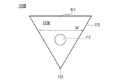
- the support member 110B may have a triangular shape without rounded corners as shown in FIG.
- the support member 110C may have a pentagonal shape as shown in FIG.
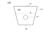
- the support member 110D may have a trapezoidal shape as shown in FIG.
- the support member 110E may have a hexagonal shape, as shown in FIG.
- the formation of the holes 117 may be omitted in the support members 110B, 110C, 110D, and 110E shown in FIGS. Further, the support members 110C, 110D, and 110E shown in FIGS. 22 to 24 may have rounded corners.
- hemostatic device according to the present invention has been described above through the embodiments and modifications, the present invention is not limited to the contents described in the specification, and can be appropriately modified based on the description of the claims. is possible.
- each part of the hemostatic device are not particularly limited as long as the pressure member placed at the puncture site can press the puncture site to stop bleeding, and can be changed as appropriate.
Landscapes
- Health & Medical Sciences (AREA)
- Life Sciences & Earth Sciences (AREA)
- Surgery (AREA)
- Engineering & Computer Science (AREA)
- Animal Behavior & Ethology (AREA)
- Vascular Medicine (AREA)
- Nuclear Medicine, Radiotherapy & Molecular Imaging (AREA)
- Veterinary Medicine (AREA)
- Public Health (AREA)
- Biomedical Technology (AREA)
- Heart & Thoracic Surgery (AREA)
- Medical Informatics (AREA)
- Molecular Biology (AREA)
- Reproductive Health (AREA)
- General Health & Medical Sciences (AREA)
- Biophysics (AREA)
- Hematology (AREA)
- Surgical Instruments (AREA)
Abstract
Description
図1~図9は、本実施形態に係る止血器具100を説明するための図、図10~図17は、止血器具100の使用例及び作用効果を説明するための図である。
止血器具100は、概説すると、図1、図2、図13、図14に示すように、第1穿刺部位p1を覆うように構成された支持部材110と、支持部材110を第1穿刺部位p1に固定するように構成された固定部材120と、支持部材110に接続され、第1穿刺部位を圧迫するように構成された押圧部材180と、を有する。なお、上記の「支持部材110に接続され、」は、押圧部材180が間接的に支持部材110に接続されることを含む。例えば、図1、図5、図6に示すように、押圧部材180(拡張部材180)が接続部材190を介して支持部材110に接続されることは、上記の「支持部材110に接続され、」に含まれる。
押圧部材180は、例えば、図6に示すように、空気等の流体を流入することが可能な内腔183を備えるバルーン等の拡張部材で構成することができる。本実施形態では、以下の説明において、押圧部材180を拡張部材で構成した例を説明する。
支持部材110は、図5、図6、図7、図8、図9に示すように、拡張部材180の先端側に位置し、支持部材110の端部を形成する上端部111と、拡張部材180の基端側に位置し、上端部111と反対側の端部を形成する下端部112と、上端部111と下端部112を繋ぐ側面部113と、を有する。
固定部材120は、図1、図2、図3、図4、図13に示すように、被覆部130と、第1帯体部140と、第2帯体部150と、第3帯体部160と、を有する。
止血器具100は、図1、図2に示すように、拡張部材180に流体を注入するための注入部201を有する。
次に、図10~図14を参照して、止血器具100の第1使用例を説明する。
第3帯体部160に配置される第2固定部位172の形状は、任意に変更することが可能である。例えば、図18に示すように、第2固定部位172は、第3帯体部160の他端部163側に二つの分岐部172a、172bが形成されたハート型のような形状で構成することも可能である。
第2実施形態に係る止血器具100Aは、図19に示すように、固定部材120が第1方向及び第2方向と異なる第3方向に延在する第3帯体部160を備える。
以下、図20~図24を参照して、支持部材の変形例を説明する。
110、110A、110B、110C、110D、110E 支持部材
110a 支持部材の下面
110b 支持部材の上面
111 支持部材の上端部
112 支持部材の下端部
113 支持部材の側面部
115a、115b、115c 支持部材の角部
120 固定部材
130 被覆部
130a 被覆部の内表面
130b 被覆部の外表面
140 第1帯体部
141 第1帯体部の一端部
143 第1帯体部の他端部
145 第1帯体部の本体部
150 第2帯体部
151 第2帯体部の一端部
153 第2帯体部の他端部
155 第2帯体部の本体部
160 第3帯体部
160a 第1部分
160b 第2部分
161 第3帯体部の一端部
163 第3帯体部の他端部
165 第3帯体部の本体部
171 第1固定部位
172 第2固定部位
172a 第1分岐部
172b 第2分岐部
173 第3固定部位
174 第4固定部位
180 拡張部材(押圧部材)
183 拡張部材の内腔
185 マーカー部
190 接続部材
191 空間部
A 前腕部
B1 人差し指の中手骨
B2 親指の中手骨
C 第1帯体部の長軸
H 手
H1 右手
H2 左手
T1 長母指伸筋腱
T2 短母伸筋腱
V1 血管(遠位橈骨動脈)
V2 動脈
fb 指間部
p1 第1穿刺部位
p2 第2穿刺部位
p3 第3穿刺部位
p4 第4穿刺部位
Claims (6)
- 患者に形成された穿刺部位を覆うように構成された支持部材と、
前記支持部材を前記患者の前記穿刺部位に固定するように構成された固定部材と、
前記支持部材に接続され、前記患者の前記穿刺部位を圧迫するように構成された押圧部材と、を有し、
前記支持部材は、前記押圧部材の先端側に位置し、前記支持部材の端部を形成する上端部と、前記押圧部材の基端側に位置し、前記上端部と反対側の端部を形成する下端部と、前記上端部と前記下端部を繋ぐ側面部と、を有し、前記押圧部材よりも大きな剛性を備え、
前記固定部材は、前記患者の指同士の間に配置するように構成され、第1方向に延在する第1帯体部と、前記第1方向と異なる第2方向に延在する第2帯体部と、を備え、
前記支持部材は、前記支持部材の幅が前記上端部から前記下端部に向かって短くなり、かつ、前記側面部の厚みが前記上端部から前記下端部に向かって薄くなるように構成されており、
前記第1帯体部は、前記上端部側から前記第1方向に延在し、
前記第2帯体部は、前記側面部側から前記第2方向に延在する、止血器具。 - 前記支持部材は、前記第1帯体部の長軸に対して左右対称の外形を有する、請求項1に記載の止血器具。
- 前記固定部材は、前記第1方向及び前記第2方向と異なる第3方向に延在する第3帯体部を備え、
前記第3帯体部は、前記支持部材を挟んで前記第2帯体部と反対側に位置する前記側面部から第3方向に延在しており、
前記第3帯体部は、前記支持部材側に位置する一端部と、前記一端部と反対側に位置する他端部と、前記一端部と前記他端部との間に延在する本体部と、を備え、
前記本体部は、前記第2帯体部に対して着脱可能に構成された固定部位を備え、
前記固定部位は、前記他端部側に位置する端部が複数の部分に分岐している、請求項1又は請求項2に記載の止血器具。 - 前記固定部材は、前記第1方向及び前記第2方向と異なる第3方向に延在する第3帯体部を備え、
前記第3帯体部は、前記支持部材を挟んで前記第2帯体部と反対側に位置する前記側面部から第3方向に延在しており、
前記第3帯体部は、前記支持部材側に位置する一端部と、前記一端部と反対側に位置する他端部と、前記一端部と前記他端部との間に延在する本体部と、を備え、
前記第3帯体部は、前記本体部で分岐している、請求項1又は請求項2に記載の止血器具。 - 前記支持部材の外周側面に位置する角部は、丸みを帯びた形状を有する、請求項1~4のいずれか1項に記載の止血器具。
- 前記支持部材は、前記押圧部材と重なる位置に孔部を有する、請求項1~5のいずれか1項に記載の止血器具。
Priority Applications (4)
| Application Number | Priority Date | Filing Date | Title |
|---|---|---|---|
| JP2023511344A JP7853283B2 (ja) | 2021-03-30 | 2022-03-29 | 止血器具 |
| EP22780867.2A EP4302709A4 (en) | 2021-03-30 | 2022-03-29 | Hemostatic instrument |
| CN202280023350.2A CN117119977B (zh) | 2021-03-30 | 2022-03-29 | 止血器具 |
| US18/468,222 US20240000462A1 (en) | 2021-03-30 | 2023-09-15 | Hemostatic device |
Applications Claiming Priority (2)
| Application Number | Priority Date | Filing Date | Title |
|---|---|---|---|
| JP2021057231 | 2021-03-30 | ||
| JP2021-057231 | 2021-03-30 |
Related Child Applications (1)
| Application Number | Title | Priority Date | Filing Date |
|---|---|---|---|
| US18/468,222 Continuation US20240000462A1 (en) | 2021-03-30 | 2023-09-15 | Hemostatic device |
Publications (1)
| Publication Number | Publication Date |
|---|---|
| WO2022210656A1 true WO2022210656A1 (ja) | 2022-10-06 |
Family
ID=83459419
Family Applications (1)
| Application Number | Title | Priority Date | Filing Date |
|---|---|---|---|
| PCT/JP2022/015311 Ceased WO2022210656A1 (ja) | 2021-03-30 | 2022-03-29 | 止血器具 |
Country Status (5)
| Country | Link |
|---|---|
| US (1) | US20240000462A1 (ja) |
| EP (1) | EP4302709A4 (ja) |
| JP (1) | JP7853283B2 (ja) |
| CN (1) | CN117119977B (ja) |
| WO (1) | WO2022210656A1 (ja) |
Cited By (2)
| Publication number | Priority date | Publication date | Assignee | Title |
|---|---|---|---|---|
| WO2023176667A1 (ja) * | 2022-03-18 | 2023-09-21 | テルモ株式会社 | 止血器具 |
| WO2025047705A1 (ja) * | 2023-08-28 | 2025-03-06 | テルモ株式会社 | 止血器具 |
Families Citing this family (1)
| Publication number | Priority date | Publication date | Assignee | Title |
|---|---|---|---|---|
| JPWO2023176664A1 (ja) * | 2022-03-18 | 2023-09-21 |
Citations (4)
| Publication number | Priority date | Publication date | Assignee | Title |
|---|---|---|---|---|
| WO2020027122A1 (ja) * | 2018-08-01 | 2020-02-06 | テルモ株式会社 | 止血器具 |
| WO2020111184A1 (ja) * | 2018-11-29 | 2020-06-04 | テルモ株式会社 | 止血器具 |
| JP2021502220A (ja) * | 2017-11-03 | 2021-01-28 | メリット・メディカル・システムズ・インコーポレイテッドMerit Medical Systems,Inc. | 止血装置及び使用方法 |
| JP2021057231A (ja) | 2019-09-30 | 2021-04-08 | 大日本印刷株式会社 | 全固体リチウムイオンバッテリー用包装材料、及び包装体 |
Family Cites Families (12)
| Publication number | Priority date | Publication date | Assignee | Title |
|---|---|---|---|---|
| DE10054188A1 (de) * | 2000-11-02 | 2002-05-16 | Laura Turkalj | Kompressionsverband |
| KR20020072631A (ko) * | 2001-03-12 | 2002-09-18 | 강종만 | 의료용 피부 확장 펼침기 |
| DE60328343D1 (de) * | 2002-07-15 | 2009-08-27 | Terumo Corp | Blutstillende Vorrichtung mit aufblasbarem Ballon |
| US7135032B2 (en) * | 2002-09-06 | 2006-11-14 | Radi Medical Systems Ab | Femoral compression device with support |
| US9332994B2 (en) * | 2013-07-12 | 2016-05-10 | Vasoinnovations, Inc. | Apparatus and method to stop bleeding |
| US9427239B2 (en) * | 2013-07-12 | 2016-08-30 | Semier Technologies, Inc. | Apparatus and method of use for an adjustable radial and ulnar compression wristband |
| WO2016118695A1 (en) * | 2015-01-21 | 2016-07-28 | Biolife, L.L.C. | Combination hemostatic tablet or powder and radial arterial compression band with syringe assembly |
| US10426490B2 (en) * | 2016-07-12 | 2019-10-01 | Reza Salimi | Transparent pressure dressing device and methods for enabling hemostasis of blood |
| WO2019199969A1 (en) * | 2018-04-11 | 2019-10-17 | Merit Medical Systems, Inc. | Inflatable compression device |
| JP2019216947A (ja) * | 2018-06-19 | 2019-12-26 | テルモ株式会社 | 止血器具 |
| US11116516B2 (en) * | 2018-08-06 | 2021-09-14 | Medtronic Vascular, Inc. | Distal radial compression device |
| CN111281572B (zh) * | 2020-03-09 | 2021-05-07 | 中国人民解放军总医院第八医学中心 | 心脏介入治疗综合辅助装置 |
-
2022
- 2022-03-29 EP EP22780867.2A patent/EP4302709A4/en active Pending
- 2022-03-29 WO PCT/JP2022/015311 patent/WO2022210656A1/ja not_active Ceased
- 2022-03-29 CN CN202280023350.2A patent/CN117119977B/zh active Active
- 2022-03-29 JP JP2023511344A patent/JP7853283B2/ja active Active
-
2023
- 2023-09-15 US US18/468,222 patent/US20240000462A1/en active Pending
Patent Citations (4)
| Publication number | Priority date | Publication date | Assignee | Title |
|---|---|---|---|---|
| JP2021502220A (ja) * | 2017-11-03 | 2021-01-28 | メリット・メディカル・システムズ・インコーポレイテッドMerit Medical Systems,Inc. | 止血装置及び使用方法 |
| WO2020027122A1 (ja) * | 2018-08-01 | 2020-02-06 | テルモ株式会社 | 止血器具 |
| WO2020111184A1 (ja) * | 2018-11-29 | 2020-06-04 | テルモ株式会社 | 止血器具 |
| JP2021057231A (ja) | 2019-09-30 | 2021-04-08 | 大日本印刷株式会社 | 全固体リチウムイオンバッテリー用包装材料、及び包装体 |
Non-Patent Citations (1)
| Title |
|---|
| See also references of EP4302709A4 |
Cited By (2)
| Publication number | Priority date | Publication date | Assignee | Title |
|---|---|---|---|---|
| WO2023176667A1 (ja) * | 2022-03-18 | 2023-09-21 | テルモ株式会社 | 止血器具 |
| WO2025047705A1 (ja) * | 2023-08-28 | 2025-03-06 | テルモ株式会社 | 止血器具 |
Also Published As
| Publication number | Publication date |
|---|---|
| EP4302709A4 (en) | 2024-07-17 |
| EP4302709A1 (en) | 2024-01-10 |
| US20240000462A1 (en) | 2024-01-04 |
| JPWO2022210656A1 (ja) | 2022-10-06 |
| CN117119977A (zh) | 2023-11-24 |
| JP7853283B2 (ja) | 2026-04-28 |
| CN117119977B (zh) | 2026-05-08 |
Similar Documents
| Publication | Publication Date | Title |
|---|---|---|
| CN110461255B (zh) | 止血器具和止血方法 | |
| JP6936223B2 (ja) | 止血器具 | |
| US20240000462A1 (en) | Hemostatic device | |
| JP4624434B2 (ja) | 止血器具 | |
| JP7236439B2 (ja) | 止血器具 | |
| JP3176074U (ja) | 止血器具 | |
| JP2020018686A (ja) | 止血器具 | |
| KR101874025B1 (ko) | 수액세트용 접착밴드 | |
| JPWO2020050367A1 (ja) | 止血器具 | |
| JP2020116313A (ja) | 止血器具、および被覆部材 | |
| EP3818951B1 (en) | Hemostatic instrument | |
| EP4487792A1 (en) | Hemostasis tool | |
| JP7523377B2 (ja) | 止血器具 | |
| JP2022175655A (ja) | 止血器具 | |
| JP2022035819A (ja) | 止血器具 | |
| WO2022176938A1 (ja) | 止血器具 | |
| EP4487793A1 (en) | Hemostasis device | |
| WO2023176667A1 (ja) | 止血器具 | |
| EP4473920A1 (en) | Hemostasis device | |
| EP4458282A1 (en) | Hemostasis device | |
| WO2023176665A1 (ja) | 止血器具 | |
| WO2022210657A1 (ja) | 止血器具 | |
| JP2025027571A (ja) | 止血器具 | |
| WO2025069897A1 (ja) | 止血器具、及び止血器具セット | |
| JP2024017621A (ja) | 止血器具 |
Legal Events
| Date | Code | Title | Description |
|---|---|---|---|
| 121 | Ep: the epo has been informed by wipo that ep was designated in this application |
Ref document number: 22780867 Country of ref document: EP Kind code of ref document: A1 |
|
| WWE | Wipo information: entry into national phase |
Ref document number: 2023511344 Country of ref document: JP |
|
| WWE | Wipo information: entry into national phase |
Ref document number: 2022780867 Country of ref document: EP |
|
| ENP | Entry into the national phase |
Ref document number: 2022780867 Country of ref document: EP Effective date: 20231002 |
|
| NENP | Non-entry into the national phase |
Ref country code: DE |