WO2022210691A1 - 飛行装置 - Google Patents
飛行装置 Download PDFInfo
- Publication number
- WO2022210691A1 WO2022210691A1 PCT/JP2022/015388 JP2022015388W WO2022210691A1 WO 2022210691 A1 WO2022210691 A1 WO 2022210691A1 JP 2022015388 W JP2022015388 W JP 2022015388W WO 2022210691 A1 WO2022210691 A1 WO 2022210691A1
- Authority
- WO
- WIPO (PCT)
- Prior art keywords
- flight
- flight device
- estimated
- control unit
- instruction signal
- Prior art date
- Legal status (The legal status is an assumption and is not a legal conclusion. Google has not performed a legal analysis and makes no representation as to the accuracy of the status listed.)
- Ceased
Links
Images


Classifications
-
- G—PHYSICS
- G01—MEASURING; TESTING
- G01G—WEIGHING
- G01G19/00—Weighing apparatus or methods adapted for special purposes not provided for in the preceding groups
- G01G19/52—Weighing apparatus combined with other objects, e.g. furniture
-
- G—PHYSICS
- G05—CONTROLLING; REGULATING
- G05D—SYSTEMS FOR CONTROLLING OR REGULATING NON-ELECTRIC VARIABLES
- G05D1/00—Control of position, course, altitude or attitude of land, water, air or space vehicles, e.g. using automatic pilots
- G05D1/08—Control of attitude, i.e. control of roll, pitch, or yaw
- G05D1/0808—Control of attitude, i.e. control of roll, pitch, or yaw specially adapted for aircraft
-
- B—PERFORMING OPERATIONS; TRANSPORTING
- B64—AIRCRAFT; AVIATION; COSMONAUTICS
- B64C—AEROPLANES; HELICOPTERS
- B64C39/00—Aircraft not otherwise provided for
- B64C39/02—Aircraft not otherwise provided for characterised by special use
- B64C39/024—Aircraft not otherwise provided for characterised by special use of the remote controlled vehicle type, i.e. RPV
-
- B—PERFORMING OPERATIONS; TRANSPORTING
- B64—AIRCRAFT; AVIATION; COSMONAUTICS
- B64D—EQUIPMENT FOR FITTING IN OR TO AIRCRAFT; FLIGHT SUITS; PARACHUTES; ARRANGEMENT OR MOUNTING OF POWER PLANTS OR PROPULSION TRANSMISSIONS IN AIRCRAFT
- B64D1/00—Dropping, ejecting, releasing or receiving articles, liquids, or the like, in flight
- B64D1/16—Dropping or releasing powdered, liquid, or gaseous matter, e.g. for fire-fighting
- B64D1/18—Dropping or releasing powdered, liquid, or gaseous matter, e.g. for fire-fighting by spraying, e.g. insecticides
-
- B—PERFORMING OPERATIONS; TRANSPORTING
- B64—AIRCRAFT; AVIATION; COSMONAUTICS
- B64U—UNMANNED AERIAL VEHICLES [UAV]; EQUIPMENT THEREFOR
- B64U10/00—Type of UAV
- B64U10/10—Rotorcrafts
- B64U10/13—Flying platforms
- B64U10/14—Flying platforms with four distinct rotor axes, e.g. quadcopters
-
- B—PERFORMING OPERATIONS; TRANSPORTING
- B64—AIRCRAFT; AVIATION; COSMONAUTICS
- B64U—UNMANNED AERIAL VEHICLES [UAV]; EQUIPMENT THEREFOR
- B64U50/00—Propulsion; Power supply
- B64U50/10—Propulsion
- B64U50/19—Propulsion using electrically powered motors
-
- B—PERFORMING OPERATIONS; TRANSPORTING
- B64—AIRCRAFT; AVIATION; COSMONAUTICS
- B64U—UNMANNED AERIAL VEHICLES [UAV]; EQUIPMENT THEREFOR
- B64U50/00—Propulsion; Power supply
- B64U50/30—Supply or distribution of electrical power
-
- G—PHYSICS
- G01—MEASURING; TESTING
- G01G—WEIGHING
- G01G19/00—Weighing apparatus or methods adapted for special purposes not provided for in the preceding groups
- G01G19/08—Weighing apparatus or methods adapted for special purposes not provided for in the preceding groups for incorporation in vehicles
-
- G—PHYSICS
- G05—CONTROLLING; REGULATING
- G05D—SYSTEMS FOR CONTROLLING OR REGULATING NON-ELECTRIC VARIABLES
- G05D1/00—Control of position, course, altitude or attitude of land, water, air or space vehicles, e.g. using automatic pilots
- G05D1/08—Control of attitude, i.e. control of roll, pitch, or yaw
- G05D1/0808—Control of attitude, i.e. control of roll, pitch, or yaw specially adapted for aircraft
- G05D1/0816—Control of attitude, i.e. control of roll, pitch, or yaw specially adapted for aircraft to ensure stability
-
- G—PHYSICS
- G05—CONTROLLING; REGULATING
- G05D—SYSTEMS FOR CONTROLLING OR REGULATING NON-ELECTRIC VARIABLES
- G05D1/00—Control of position, course, altitude or attitude of land, water, air or space vehicles, e.g. using automatic pilots
- G05D1/10—Simultaneous control of position or course in three dimensions
- G05D1/101—Simultaneous control of position or course in three dimensions specially adapted for aircraft
- G05D1/106—Change initiated in response to external conditions, e.g. avoidance of elevated terrain or of no-fly zones
-
- G—PHYSICS
- G05—CONTROLLING; REGULATING
- G05D—SYSTEMS FOR CONTROLLING OR REGULATING NON-ELECTRIC VARIABLES
- G05D1/00—Control of position, course, altitude or attitude of land, water, air or space vehicles, e.g. using automatic pilots
- G05D1/40—Control within particular dimensions
- G05D1/49—Control of attitude, i.e. control of roll, pitch or yaw
- G05D1/495—Control of attitude, i.e. control of roll, pitch or yaw to ensure stability
-
- B—PERFORMING OPERATIONS; TRANSPORTING
- B64—AIRCRAFT; AVIATION; COSMONAUTICS
- B64U—UNMANNED AERIAL VEHICLES [UAV]; EQUIPMENT THEREFOR
- B64U2101/00—UAVs specially adapted for particular uses or applications
- B64U2101/40—UAVs specially adapted for particular uses or applications for agriculture or forestry operations
-
- B—PERFORMING OPERATIONS; TRANSPORTING
- B64—AIRCRAFT; AVIATION; COSMONAUTICS
- B64U—UNMANNED AERIAL VEHICLES [UAV]; EQUIPMENT THEREFOR
- B64U2101/00—UAVs specially adapted for particular uses or applications
- B64U2101/45—UAVs specially adapted for particular uses or applications for releasing liquids or powders in-flight, e.g. crop-dusting
-
- B—PERFORMING OPERATIONS; TRANSPORTING
- B64—AIRCRAFT; AVIATION; COSMONAUTICS
- B64U—UNMANNED AERIAL VEHICLES [UAV]; EQUIPMENT THEREFOR
- B64U2201/00—UAVs characterised by their flight controls
- B64U2201/10—UAVs characterised by their flight controls autonomous, i.e. by navigating independently from ground or air stations, e.g. by using inertial navigation systems [INS]
-
- B—PERFORMING OPERATIONS; TRANSPORTING
- B64—AIRCRAFT; AVIATION; COSMONAUTICS
- B64U—UNMANNED AERIAL VEHICLES [UAV]; EQUIPMENT THEREFOR
- B64U2201/00—UAVs characterised by their flight controls
- B64U2201/20—Remote controls
-
- B—PERFORMING OPERATIONS; TRANSPORTING
- B64—AIRCRAFT; AVIATION; COSMONAUTICS
- B64U—UNMANNED AERIAL VEHICLES [UAV]; EQUIPMENT THEREFOR
- B64U30/00—Means for producing lift; Empennages; Arrangements thereof
- B64U30/20—Rotors; Rotor supports
-
- Y—GENERAL TAGGING OF NEW TECHNOLOGICAL DEVELOPMENTS; GENERAL TAGGING OF CROSS-SECTIONAL TECHNOLOGIES SPANNING OVER SEVERAL SECTIONS OF THE IPC; TECHNICAL SUBJECTS COVERED BY FORMER USPC CROSS-REFERENCE ART COLLECTIONS [XRACs] AND DIGESTS
- Y02—TECHNOLOGIES OR APPLICATIONS FOR MITIGATION OR ADAPTATION AGAINST CLIMATE CHANGE
- Y02T—CLIMATE CHANGE MITIGATION TECHNOLOGIES RELATED TO TRANSPORTATION
- Y02T50/00—Aeronautics or air transport
- Y02T50/60—Efficient propulsion technologies, e.g. for aircraft
Definitions
- the present invention relates to flight devices.
- flying devices capable of unmanned flight in the air have been known.
- Such a flight device is capable of flying in the air with the thrust of a rotor rotationally driven around a vertical axis.
- Flight devices include, for example, transportation, surveying, photography, and agriculture.
- the flight device is equipped with various devices and medicines.
- Patent Literature 1 and Patent Literature 2 describe inventions for estimating the remaining amount of fuel in a tank of a flight device.
- Patent document 1 has a load cell as a weight measuring device.
- a load cell can be used to measure the weight difference from the weight of an empty tank and detect the remaining amount of the attached tank during pesticide application. Therefore, it is possible to detect the remaining amount of pesticide without using a flow meter.
- Patent Literature 2 describes remaining amount acquisition means for acquiring remaining amount information of the content of the aerosol container.
- information on the remaining amount of the contents of the aerosol container is detected by a weight sensor.
- Patent Documents 1 and 2 are equipped with dedicated load cells and weight sensors to detect the remaining amount in the tank, which may lead to high costs. rice field.
- the load acting on the load cell and weight sensor may not accurately reflect the remaining amount in the tank.
- the present invention has been made in view of the above circumstances, and its object is to provide a flight device capable of accurately measuring the weight of a carrier with a simple configuration.
- a flight device of the present invention includes a rotor, a motor, a flight sensor, a power conversion unit, and an arithmetic control unit, and is a flight device for transporting a vehicle.
- the motor rotates the rotor
- the flight sensor measures physical quantities acting on the airframe base
- the arithmetic control unit measures the physical quantity.
- an instruction signal is generated so as to set the airframe base portion to a predetermined position and orientation
- the power conversion unit adjusts the amount of electric power supplied to the motor based on the inputted instruction signal
- the arithmetic control unit is characterized by calculating an estimated weight, which is an estimated value of the weight of the transportation body, based on the magnitude of the instruction signal.
- the flight device of the present invention further comprises a spraying device, the transporter is a chemical sprayed by the spraying device, and the arithmetic control unit controls the chemical agent based on the magnitude of the instruction signal. and calculating an estimated remaining amount, which is an estimated value of the remaining amount of the battery.
- a plurality of the rotors, the motors, and the power conversion units are provided, and the arithmetic control unit generates a plurality of the instruction signals to be input to each of the power conversion units, Further, the estimated weight of the transporter is estimated based on an instruction signal average value, which is an average value of the instruction signals.
- the flight device of the present invention further includes a battery that supplies electric power to the power conversion unit, and the arithmetic control unit calculates the estimated weight based on the instruction signal and the voltage value of the battery. It is characterized by
- the signal indicating the estimated weight is transmitted to a display device, and the estimated weight is displayed on the display section of the display device.
- a flight device of the present invention includes a rotor, a motor, a flight sensor, a power conversion unit, and an arithmetic control unit, and is a flight device for transporting a vehicle.
- the motor rotates the rotor
- the flight sensor measures physical quantities acting on the airframe base
- the arithmetic control unit measures the physical quantity.
- an instruction signal is generated so as to set the airframe base portion to a predetermined position and orientation
- the power conversion unit adjusts the amount of electric power supplied to the motor based on the inputted instruction signal
- the arithmetic control unit is characterized by calculating an estimated weight, which is an estimated value of the weight of the transportation body, based on the magnitude of the instruction signal. Therefore, according to the flight device of the present invention, the weight of the transport body can be estimated from the instruction signal generated to bring the airframe base into the predetermined position and orientation. Therefore, it is possible to estimate the weight of the carrier without using a dedicated weight sensor.
- the flight device of the present invention further comprises a spraying device, the transporter is a chemical sprayed by the spraying device, and the arithmetic control unit controls the chemical agent based on the magnitude of the instruction signal. and calculating an estimated remaining amount, which is an estimated value of the remaining amount of the battery. Therefore, according to the flying device of the present invention, the remaining amount of sprayed medicine can be estimated in real time.
- the flight device of the present invention a plurality of the rotors, the motors, and the power conversion units are provided, and the arithmetic control unit generates a plurality of the instruction signals to be input to each of the power conversion units, Further, the estimated weight of the transporter is estimated based on an instruction signal average value, which is an average value of the instruction signals. Therefore, according to the flight device of the present invention, by estimating the estimated weight of the transporter based on the average value of the instruction signals, the weight of the transporter can be stabilized in both the hovering state and the moving state. can be reasonably estimated.
- the flight device of the present invention further includes a battery that supplies electric power to the power conversion unit, and the arithmetic control unit calculates the estimated weight based on the instruction signal and the voltage value of the battery. It is characterized by Therefore, according to the flight device of the present invention, the estimated weight can be calculated more accurately by taking into consideration the voltage value of the battery in addition to the command signal when calculating the estimated weight.
- the signal indicating the estimated weight is transmitted to a display device, and the estimated weight is displayed on the display section of the display device. Therefore, according to the flight device of the present invention, for example, an operator who operates the flight device can know the estimated weight of the transport in real time.
- FIG. 4 is a flow chart showing a method of calculating an estimated weight value of a vehicle in the flight device according to the embodiment of the present invention; 4 is a graph showing temporal changes in motor output value and spraying state in the flight device according to the embodiment of the present invention. 4 is a graph showing changes over time in the motor output value and the movement speed of the flight device in the flight device according to the embodiment of the present invention.
- the flight device 10 will be described below with reference to the drawings.
- the same reference numerals are given to the same members in principle, and repeated descriptions will be omitted.
- up, down, front, back, left, and right directions are used, but left and right are left and right when the flight device 10 is viewed from the front in FIG. 1(A).
- FIG. 1(A) is a top view showing the flight device 10
- FIG. 1(B) is a front view showing the flight device 10.
- a flight device 10 includes a fuselage base portion 16, a power unit (not shown) mounted on the fuselage base portion 16, and a peripheral portion of the fuselage base portion 16 extending toward the periphery. It mainly includes an arm 271, etc., a motor 121, etc. arranged at the outer end of the arm 271, etc., and a rotor 111, etc. rotated by the motor 121, etc.
- the motor 121 and the like are collectively referred to as the motor 12 and the rotor 111 and the like are collectively referred to as the rotor 11 .
- the flight device 10 uses electric power obtained from the battery housed in the fuselage base portion 16 to rotate the rotor 111 and the like with the motor 121 and the like at a predetermined rotational speed, enabling it to float and move in the air.
- a flying device 10 for spraying agricultural chemicals on fields such as paddy fields is illustrated.
- the fuselage base section 16 is arranged in the center of the flight device 10, and houses various devices not shown here.
- the skin of the body base portion 16 is covered with a synthetic resin plate or steel plate formed into a predetermined shape.
- a drug tank 29 for storing a drug 20, which will be described later, is built in the body base portion 16. As shown in FIG.
- An arm 271 , an arm 272 , an arm 273 and an arm 274 extend outward from the power converter 14 .
- a motor 121 and a rotor 111 are arranged at the outer end of the arm 271 .
- Motor 122 and rotor 112 are located at the outer end of arm 272 .
- Motor 123 and rotor 113 are arranged at the outer end of arm 273 .
- Motor 124 and rotor 114 are located at the outer end of arm 274 .
- the rotor 111 and the like generate a thrust for floating the body base portion 16 by rotating.
- the motor 121 and the like rotate the rotor 111 and the like.
- Liquid pesticides, granular pesticides, etc. can be used as the pesticides 20 stored in the pesticide tank 29 .
- a leg section 32 and a leg section 33 that contact the ground during landing are arranged in the lower part of the fuselage base section 16 .
- the legs 32 and 33 are members also called skids, and when the flight device 10 lands, the lower ends of the legs 32 and 33 are in contact with the ground.
- a spraying device 18 for spraying the medicine 20 is arranged below the body base portion 16 .
- the spraying device 18 incorporates a pump for transporting the drug 20. As shown in FIG.
- a support arm 19 extending upward to the right is connected to the leg portion 32 , and a nozzle 36 is installed at the upper end of the support arm 19 .
- the leg portion 33 is connected to a support arm 34 extending upward on the left side, and a nozzle 35 is installed at the upper end of the support arm 34 .
- the nozzles 35 and 36 and the spraying device 18 are connected via pipes 37 .
- the spraying device 18 operates the pump of the spraying device 18 during the spraying ON state based on instructions from the controller 28, which will be described later. By doing so, the medicine 20 stored in the medicine tank 29 is sprayed downward from the nozzles 35 and 36 via the pipe 37 by the pressure of the spraying device 18 . On the other hand, during the spraying off state, the pump of the spraying device 18 is not operated and the chemical agent 20 is not sprayed from the nozzles 35 and 36 based on instructions from the controller 28, which will be described later.
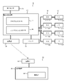
- FIG. 2 is a block diagram showing the connection configuration of the flight device 10. As shown in FIG.
- the flight device 10 mainly includes a motor 121, etc., a flight sensor 13, a power conversion section 14, and an arithmetic control section 15, and transports a drug 20 as a transporter. Further, the flight device 10 has a communication section 25 , a battery 21 and a power conversion section 14 .
- the operator 28 is operated on the ground by the operator who operates the flight device 10 . Also, the communication unit 26, the display device 22, and the display unit 23 are installed near the operator.
- the flight sensor 13 measures the physical quantity acting on the fuselage base portion 16 and transmits a signal indicating the size of this physical quantity to the arithmetic control section 15 .
- Sensors included in the flight sensor 13 are, for example, an acceleration sensor, an angular velocity sensor, a geomagnetic sensor, an atmospheric pressure sensor, and a GNSS antenna.
- the acceleration sensor detects changes in inclination and movement as physical quantities.
- the angular velocity sensor detects changes in inclination and orientation as physical quantities.
- a geomagnetic sensor detects a direction as a physical quantity by magnetic force.
- An atmospheric pressure sensor detects altitude as a physical quantity.
- a GNSS antenna determines the location.
- the arithmetic control unit 15 has an arithmetic device consisting of a CPU (Central Processing Unit) and a storage device consisting of a RAM (Random Access Memory) and a ROM (Read Only Memory), and controls the operation of the entire flight device 10. . Further, the arithmetic control unit 15 adjusts the amount of electric power supplied to the motor 121 and the like based on the instruction signal input from the flight sensor 13, as will be described later. Furthermore, as will be described later, the arithmetic control unit 15 calculates an estimated remaining amount, which is an estimated value of the remaining amount of the drug 20, which is a carrier, based on the magnitude of the instruction signal.
- an estimated remaining amount which is an estimated value of the remaining amount of the drug 20, which is a carrier
- the arithmetic control unit 15 has a flight controller 17 and a companion controller 24.
- the flight controller 17 generates an instruction signal for setting the position, attitude, movement speed, etc. of the flight device 10 based on the signal input from the flight sensor 13 .
- This instruction signal for example, a DUTY value in PWM control can be adopted.
- the DUTY value for each motor 121 is calculated.
- the companion controller 24 calculates the estimated remaining amount of the drug 20 based on information input from the flight controller 17, such as information input from the flight sensor 13, information indicating the voltage of the battery 21, and the like.
- the power conversion unit 14 has ESCs 141 to 144.
- ESC is an abbreviation for Electric Speed Controller, which is an electronic device that controls the number of revolutions of the motor 12 .
- the ESC 141 is arranged between the motor 121 and the arithmetic control unit 15 and controls the rotation speed of the motor 121 .
- the ESC 142 is arranged between the motor 122 and the arithmetic control unit 15 and controls the rotation speed of the motor 122 .
- the ESC 143 is arranged between the motor 123 and the arithmetic control section 15 and controls the rotation speed of the motor 123 .
- the ESC 144 is arranged between the motor 124 and the arithmetic control section 15 and controls the rotation speed of the motor 124 .
- ESC 141 through ESC 144 rotate motors 121 through 124 at high speed if the DUTY value input from flight controller 17 is large.
- the flight device 10 is capable of performing each operation of ascending operation, hovering operation, moving operation and descending operation.
- the operation of the flight device 10 is executed by the flight controller 17 based on commands transmitted from the pilot plane 28 based on the operations of the operator.
- the flight controller 17 controls the motor 121 or motor controller 121 so that the flight device 10 assumes a predetermined attitude based on information input from the acceleration sensor and the angular velocity sensor included in the flight sensor 13 . 124 rotation speed is adjusted.
- the flight controller 17 rotates the motor 12 at a relatively high speed so that the flight device 10 ascends to a predetermined altitude.
- the flight controller 17 basically outputs substantially the same DUTY value to the ESCs 141 to 144 and makes the rotational speeds of the motors 121 to 124 substantially the same. Further, the flight controller 17 performs a hovering operation to keep the altitude of the flight device 10 substantially constant when the flight device 10 ascends to a predetermined altitude based on the information input from the air pressure sensor included in the flight sensor 13 .
- the flight controller 17 adjusts the rotational speeds of the motors 121 and 122 based on information input from the air pressure sensor included in the flight sensor 13 so that the altitude of the flight device 10 is substantially constant. ing.
- the flight controller 17 outputs substantially the same DUTY value to the ESCs 141 to 144, and makes the rotational speeds of the motors 121 to 124 substantially the same.
- the flight controller 17 adjusts the rotational speeds of the motors 121 to 124 so that the flight device 10 can move forward, backward, leftward, and rightward at a predetermined speed.
- the rotational speeds of motors 121 and 122 are made faster than the rotational speeds of motors 123 and 124 . That is, the flight controller 17 makes the DUTY value output to ESC141 and ESC142 larger than the DUTY value output to ESC143 and ESC144.
- rotors 111 and 112 rotate at a higher speed than rotors 113 and 114, and fuselage base portion 16 of flight device 10 assumes a tilted posture, resulting in flight.
- Device 10 moves in a predetermined direction.
- the flight controller 17 when the flight controller 17 recognizes that the flight device 10 has reached a predetermined position based on the output of the GNSS antenna, etc. included in the flight sensor 13, the flight controller 17 performs a braking operation. For example, the flight controller 17 makes the rotational speeds of the motors 121 and 122 slower than the rotational speeds of the motors 123 and 124 . That is, the flight controller 17 makes the DUTY value output to ESC143 and ESC144 larger than the DUTY value output to ESC141 and ESC142. By doing so, referring to FIG. 1A, rotors 111 and 112 rotate at a lower speed than rotors 113 and 114, and plane movement of flight device 10 can be stopped. . After that, the flight controller 17 performs a hovering operation.
- the flight controller 17 rotates the motor 12 at a relatively low speed so that the flight device 10 descends to a predetermined altitude.
- the flight controller 17 basically outputs substantially the same DUTY value to the ESCs 141 to 144 and makes the rotational speeds of the motors 121 to 124 substantially the same. Further, the flight controller 17 performs a hovering operation to keep the altitude of the flight device 10 substantially constant after the flight device 10 descends to a predetermined altitude based on the information input from the air pressure sensor included in the flight sensor 13 .
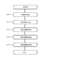
- FIG. 3 is a flow chart showing a method for calculating the estimated remaining amount of the drug 20, which is the carrier, in the flight device 10.
- the flight sensor 13 measures physical quantities. Specifically, an acceleration sensor, an angular velocity sensor, a geomagnetic sensor, an air pressure sensor, a GNSS antenna, and the like included in the flight sensor 13 measure the position and orientation of the flight device 10 . Physical quantities measured by the flight sensor 13 are input to the flight controller 17 . In addition, the operational status of the flight device 10 during flight is also input to the flight controller 17 .
- step S11 the flight controller 17 calculates a DUTY value as an instruction signal based on the physical quantity described above.
- the flight controller 17 outputs a DUTY value based on the various information input in step S10, the operational status, and the like.
- the flight controller 17 calculates a DUTY value for each of the ESCs 141 through 144 shown in FIG.
- the DUTY value also changes depending on the weight of the flight device 10 containing the drug 20. That is, when spraying agricultural chemicals, it is necessary to keep the altitude of the flight device 10 substantially the same in order to effectively spray the agricultural chemicals on plants such as rice. Moreover, since the weight of the chemical agent 20 is heavy at the beginning of pesticide spraying, the DUTY value selected by the flight controller 17 is relatively large. On the other hand, as the pesticide spraying progresses, the weight of the chemical agent 20 becomes lighter, so the DUTY value selected by the flight controller 17 becomes relatively smaller.
- the flight controller 17 may average the DUTY values calculated for each of the ESCs 141 to 144 in order to accurately estimate the weight of the medicine 20 in a later step.
- the DUTY value calculated for each of ESC 141 to ESC 144 varies depending on the attitude and flight state of flight device 10 . Therefore, by calculating the DUTY average value (instruction signal average value), which is the average value of these four DUTY values, the influence of the attitude and flight conditions can be eliminated. Therefore, as will be described later, the estimated remaining amount of the medicine 20 can be accurately calculated from the average value of the DUTY values regardless of the flight state of the flight device 10 .
- the calculated DUTY average value is input to the companion controller 24 .
- the companion controller 24 calculates the estimated remaining amount of the medicine 20, which is the estimated weight value. Specifically, the companion controller 24 reads the DUTY average value and the battery voltage value, which is the voltage value of the battery 21 . Then, the estimated remaining amount of the drug 20 is calculated based on a predetermined function having the DUTY average value and the battery voltage value as variables.
- the estimated remaining amount of the drug 20 is calculated in consideration of the DUTY average value and the battery voltage value.
- the reason is that the flight controller 17 increases the DUTY value in order to rotate the motor 12 at a predetermined rotational speed when the battery voltage value becomes low. Therefore, as the spraying of the medicine 20 using the flying device 10 progresses, the DUTY value gradually increases. Therefore, if the estimated remaining amount of the medicine 20 is calculated using only the DUTY value as a variable, the estimated remaining amount is calculated excessively. there is a risk of it happening. Therefore, in this embodiment, the estimated remaining amount of the medicine 20 is accurately calculated by correcting the DUTY value based on the battery voltage value.
- step S13 the companion controller 24 and the flight controller 17 transmit information indicating the estimated remaining amount of the medicine 20. Specifically, information indicating the estimated remaining amount of medicine 20 is transmitted from flight device 10 to display device 22 via communication unit 25 and pilot device 28 by wireless communication.
- step S14 the estimated remaining amount of the medicine 20 is displayed on the display unit 23 of the display device 22.
- the operator can know the estimated remaining amount of the medicine 20 by viewing the display unit 23 . Therefore, when the estimated remaining amount of the medicine 20 becomes equal to or less than a certain level, the operator can move the flying device 10 to a predetermined location and replenish the medicine 20 .
- FIG. 4 is a graph showing temporal changes in the motor output value and the spraying state in the flight device 10.
- FIG. The horizontal axis of this graph indicates the elapsed time, and the vertical axis indicates the motor output (DUTY value) and the ON/OFF state of the spray switch.
- the chemical 20 is sprayed from the spraying device 18 when the spraying switch is in the ON state.
- the spraying switch is in the OFF state, the chemical 20 is not sprayed from the spraying device 18 .
- the DUTY values output from the flight controller 17 to each of the ESCs 141 through 144 for rotating the four motors 121 through 124 provided in the flight device 10 are shown.
- the DUTY value output to the ESC 141 is indicated by a solid line
- the DUTY value output to the ESC 142 is indicated by a dashed line
- the DUTY value output to the ESC 143 is indicated by a one-dot chain line
- the DUTY value output to the ESC 144 is indicated by a two-dot chain line.
- the ON/OFF state of the spray switch is indicated by a solid line.
- the DUTY values input to ESC141 to ESC144 in this graph gradually decrease over time while the spray switch is on.
- the DUTY value input to ESC 141 to ESC 144 does not change while the spray switch is in the OFF state.
- the reason why such an event is shown is that while the spray switch is in the ON state, the remaining amount of the drug 20 gradually decreases, and the DUTY value required to keep the altitude of the flight device 10 constant decreases. is. Therefore, the amount of decrease in the DUTY value has a positive correlation with the amount of decrease in the medicine 20, and it can be understood that the remaining amount of the medicine 20 can be estimated from the DUTY value.
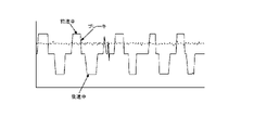
- FIG. 5 is a graph showing temporal changes in the motor output value and the movement speed of the flight device 10 in the flight device 10 .
- the horizontal axis of this graph indicates the elapsed time, and the vertical axis indicates the pitch operation (forward/backward operation) and motor average output (DUTY average value) of the flight device 10 .
- a solid line indicates the pitch operation, and a dotted line indicates the average motor output.
- the flight device 10 can move forward, brake, and reverse by operating the pilot plane 28 by the operator. Such operations are repeated when the flying device 10 sprays agricultural chemicals.
- the flight device 10 moves forward, brakes, and reverses, the DUTY values input from the flight controller 17 to each of the ESCs 141 to 144 change greatly.
- the remaining amount of the medicine 20 can be stably and accurately estimated regardless of the operating state of the flying device 10 .
- the above-described present embodiment can provide the following main effects.
- the weight of the carrier can be estimated from the command signal generated to bring the airframe base portion 16 into a predetermined position and orientation. Therefore, it is possible to estimate the weight of the carrier without using a dedicated weight sensor.
- the remaining amount of the medicine 20 can always be calculated from the DUTY average value, the remaining amount of the sprayed medicine 20 can be estimated in real time.
- the estimated weight of the medicine 20 can be stably calculated in both the hovering state and the moving state.
- the voltage value of the battery 21 is taken into consideration in addition to the DUTY average value, so that the estimated weight can be calculated more accurately.
- FIG. 1 illustrates an electric drone that uses only a battery as an energy source as the flight device 10
- a hybrid drone that uses an engine and a battery as an energy source can also be used.
- the estimated remaining amount of the medicine 20 was calculated based on the average DUTY value, but the estimated remaining amount can also be calculated using non-averaged DUTY values.
- the estimated remaining capacity can be calculated using any one of the DUTY values, the median value of the DUTY values, or the like.
- the estimated remaining amount of medicine 20 was calculated based on the average DUTY value and the battery voltage value, but the estimated remaining amount can also be calculated using only the average DUTY value.
- the remaining amount of the drug 20 as the transporter is estimated from the DUTY value, but an object other than the drug 20 can be used as the transporter.
- Flight device 11 Rotor 111 Rotor 112 Rotor 113 Rotor 114 Rotor 12 Motor 121 Motor 122 Motor 123 Motor 124 Motor 13 Flight sensor 14 Power converter 141 ESC 142 ESCs 143 ESC 144 ESC 15 Arithmetic control unit 16 Airframe base unit 17 Flight controller 18 Spray device 19 Support arm 20 Medicine 21 Battery 22 Display device 23 Display unit 24 Companion controller 25 Communication unit 26 Communication unit 271 Arm 272 Arm 273 Arm 274 Arm 28 Manipulator 29 Chemical tank 32 leg 33 leg 34 support arm 35 nozzle 36 nozzle 37 pipe
Landscapes
- Engineering & Computer Science (AREA)
- Aviation & Aerospace Engineering (AREA)
- Chemical & Material Sciences (AREA)
- Combustion & Propulsion (AREA)
- Physics & Mathematics (AREA)
- General Physics & Mathematics (AREA)
- Remote Sensing (AREA)
- Automation & Control Theory (AREA)
- Radar, Positioning & Navigation (AREA)
- Mechanical Engineering (AREA)
- Life Sciences & Earth Sciences (AREA)
- Pest Control & Pesticides (AREA)
- Catching Or Destruction (AREA)
Abstract
Description
11 ロータ
111 ロータ
112 ロータ
113 ロータ
114 ロータ
12 モータ
121 モータ
122 モータ
123 モータ
124 モータ
13 飛行センサ
14 電力変換部
141 ESC
142 ESC
143 ESC
144 ESC
15 演算制御部
16 機体ベース部
17 フライトコントローラ
18 散布装置
19 支持アーム
20 薬剤
21 バッテリ
22 表示装置
23 表示部
24 コンパニオンコントローラ
25 通信部
26 通信部
271 アーム
272 アーム
273 アーム
274 アーム
28 操縦機
29 薬剤タンク
32 脚部
33 脚部
34 支持アーム
35 ノズル
36 ノズル
37 パイプ
Claims (5)
- ロータと、モータと、飛行センサと、電力変換部と、演算制御部と、を具備し、輸送体を輸送する飛行装置であり、
前記ロータは、回転することで、機体ベース部を浮遊させるための推力を発生させ、
前記モータは、前記ロータを回転駆動し、
前記飛行センサは、前記機体ベース部に作用する物理量を計測し、
前記演算制御部は、前記物理量に基づいて、前記機体ベース部を所定の位置姿勢とするべく、指示信号を生成し、
前記電力変換部は、入力される前記指示信号に基づいて、前記モータに供給される電力量を調整し、
更に、前記演算制御部は、前記指示信号の大きさに基づいて、前記輸送体の重量の推定値である推定重量を算出することを特徴とする飛行装置。 - 散布装置を、更に具備し、
前記輸送体は、前記散布装置が散布する薬剤であり、
前記演算制御部は、前記指示信号の大きさに基づいて、前記薬剤の残量の推定値である推定残量を算出することを特徴とする請求項1に記載の飛行装置。 - 前記ロータ、前記モータおよび前記電力変換部を、複数有し、
前記演算制御部は、
各々の前記電力変換部に入力される複数の前記指示信号を生成し、
更に、前記指示信号の平均値である指示信号平均値に基づいて、前記輸送体の前記推定重量を推定することを特徴とする請求項1または請求項2に記載の飛行装置。 - 前記電力変換部に電力を供給するバッテリを、更に具備し、
前記演算制御部は、
前記指示信号および前記バッテリの電圧値に基づいて、前記推定重量を算出することを特徴とする請求項1から請求項3の何れかに記載の飛行装置。 - 前記推定重量を示す信号は、表示装置に伝送され、
前記表示装置の表示部には、前記推定重量が映し出されることを特徴とする請求項1から請求項4の何れかに記載の飛行装置。
Priority Applications (2)
| Application Number | Priority Date | Filing Date | Title |
|---|---|---|---|
| EP22780902.7A EP4316983A4 (en) | 2021-04-02 | 2022-03-29 | Flight device |
| US17/928,380 US12339157B2 (en) | 2021-04-02 | 2022-03-29 | Flight device |
Applications Claiming Priority (2)
| Application Number | Priority Date | Filing Date | Title |
|---|---|---|---|
| JP2021063661A JP6901815B1 (ja) | 2021-04-02 | 2021-04-02 | 飛行装置 |
| JP2021-063661 | 2021-04-02 |
Publications (1)
| Publication Number | Publication Date |
|---|---|
| WO2022210691A1 true WO2022210691A1 (ja) | 2022-10-06 |
Family
ID=76753115
Family Applications (1)
| Application Number | Title | Priority Date | Filing Date |
|---|---|---|---|
| PCT/JP2022/015388 Ceased WO2022210691A1 (ja) | 2021-04-02 | 2022-03-29 | 飛行装置 |
Country Status (5)
| Country | Link |
|---|---|
| US (1) | US12339157B2 (ja) |
| EP (1) | EP4316983A4 (ja) |
| JP (3) | JP6901815B1 (ja) |
| CN (1) | CN115167499B (ja) |
| WO (1) | WO2022210691A1 (ja) |
Families Citing this family (8)
| Publication number | Priority date | Publication date | Assignee | Title |
|---|---|---|---|---|
| US12246835B2 (en) * | 2018-02-28 | 2025-03-11 | Nileworks Inc. | Drone, control method thereof, and program |
| CA3035225A1 (en) * | 2019-02-28 | 2020-08-28 | Daniel Mccann | System and method for field treatment and monitoring |
| JP6990477B1 (ja) * | 2021-09-14 | 2022-01-12 | 株式会社石川エナジーリサーチ | 飛行装置 |
| WO2023060350A1 (en) * | 2021-10-13 | 2023-04-20 | Precision Ai Inc. | Hybrid aerial vehicle with adjustable vertical lift for field treatment |
| JP7838755B2 (ja) * | 2022-03-29 | 2026-04-01 | 株式会社石川エナジーリサーチ | 飛行装置 |
| JP2024038901A (ja) * | 2022-09-08 | 2024-03-21 | 株式会社石川エナジーリサーチ | 飛行装置 |
| JP7170364B1 (ja) * | 2022-09-08 | 2022-11-14 | 株式会社石川エナジーリサーチ | 飛行装置 |
| JP7680567B2 (ja) | 2022-09-30 | 2025-05-20 | 富士フイルム株式会社 | 脂肪模擬組成物、及び代替肉 |
Citations (4)
| Publication number | Priority date | Publication date | Assignee | Title |
|---|---|---|---|---|
| WO2020090671A1 (ja) * | 2018-10-30 | 2020-05-07 | 株式会社ナイルワークス | ドローン、ドローンの制御方法、および、ドローン制御プログラム |
| WO2020137554A1 (ja) * | 2018-12-27 | 2020-07-02 | 株式会社ナイルワークス | ドローン、ドローンの制御方法、および、ドローン制御プログラム |
| JP2020117203A (ja) | 2019-01-23 | 2020-08-06 | 東光鉄工株式会社 | ドローンの重量測定装置 |
| JP2020142772A (ja) | 2019-03-08 | 2020-09-10 | 東洋製罐株式会社 | 飛行体の吐出システム |
Family Cites Families (16)
| Publication number | Priority date | Publication date | Assignee | Title |
|---|---|---|---|---|
| JP2003159674A (ja) | 2001-11-21 | 2003-06-03 | Sony Corp | ロボット装置、ロボット装置の外力検出方法及びロボット装置の外力検出プログラム、並びにロボット装置の外力検出のためのキャリブレーション方法及びロボット装置の外力検出のためのキャリブレーションプログラム |
| WO2015029996A1 (ja) * | 2013-08-30 | 2015-03-05 | 電気化学工業株式会社 | 被覆材用樹脂組成物 |
| CN105874397A (zh) * | 2014-11-28 | 2016-08-17 | 深圳市大疆创新科技有限公司 | 无人机及其水样检测方法 |
| CN205353316U (zh) * | 2015-12-03 | 2016-06-29 | 杨珊珊 | 一种电动无人机 |
| JP6704293B2 (ja) | 2016-05-17 | 2020-06-03 | 日立オートモティブシステムズ株式会社 | インバータ制御装置および電力変換装置 |
| KR101668981B1 (ko) * | 2016-07-14 | 2016-10-25 | 농업회사법인 주식회사 대한무인항공서비스 | 무인항공 살포기 및 그를 이용한 살포 방법 |
| GB2568188B (en) * | 2016-09-09 | 2022-03-30 | Walmart Apollo Llc | Geographic area monitoring systems and methods that balance power usage between multiple unmanned vehicles |
| CN109803887B (zh) * | 2016-09-30 | 2022-10-04 | 日本电产株式会社 | 多轴飞行器的控制系统 |
| WO2018110598A1 (ja) | 2016-12-13 | 2018-06-21 | 株式会社自律制御システム研究所 | 無人航空機、無人航空機の制御装置、無人航空機の制御方法、及び無人航空機の障害検出装置 |
| CN107140195A (zh) * | 2017-05-12 | 2017-09-08 | 王跃辉 | 一种农用无人机 |
| US12246835B2 (en) * | 2018-02-28 | 2025-03-11 | Nileworks Inc. | Drone, control method thereof, and program |
| CN108522475A (zh) * | 2018-05-10 | 2018-09-14 | 成都信息工程大学 | 基于液压套筒调节喷洒头位置的智能型农药喷洒无人机 |
| JP6777355B2 (ja) * | 2018-06-04 | 2020-10-28 | 株式会社ナイルワークス | ドローンシステム、ドローンシステムの制御方法、およびドローンシステムの制御プログラム |
| JP7256637B2 (ja) * | 2018-12-12 | 2023-04-12 | 株式会社Subaru | 冗長アクチュエータシステム |
| JP7382860B2 (ja) | 2019-03-14 | 2023-11-17 | 愛三工業株式会社 | マルチコプタ |
| JP6630893B1 (ja) | 2019-03-28 | 2020-01-15 | 光司商会株式会社 | 吊り作業支援システム |
-
2021
- 2021-04-02 JP JP2021063661A patent/JP6901815B1/ja active Active
- 2021-06-11 JP JP2021097979A patent/JP7685213B2/ja active Active
- 2021-09-08 CN CN202111048632.1A patent/CN115167499B/zh active Active
-
2022
- 2022-03-29 US US17/928,380 patent/US12339157B2/en active Active
- 2022-03-29 EP EP22780902.7A patent/EP4316983A4/en active Pending
- 2022-03-29 WO PCT/JP2022/015388 patent/WO2022210691A1/ja not_active Ceased
-
2024
- 2024-12-25 JP JP2024228436A patent/JP7633749B1/ja active Active
Patent Citations (4)
| Publication number | Priority date | Publication date | Assignee | Title |
|---|---|---|---|---|
| WO2020090671A1 (ja) * | 2018-10-30 | 2020-05-07 | 株式会社ナイルワークス | ドローン、ドローンの制御方法、および、ドローン制御プログラム |
| WO2020137554A1 (ja) * | 2018-12-27 | 2020-07-02 | 株式会社ナイルワークス | ドローン、ドローンの制御方法、および、ドローン制御プログラム |
| JP2020117203A (ja) | 2019-01-23 | 2020-08-06 | 東光鉄工株式会社 | ドローンの重量測定装置 |
| JP2020142772A (ja) | 2019-03-08 | 2020-09-10 | 東洋製罐株式会社 | 飛行体の吐出システム |
Non-Patent Citations (1)
| Title |
|---|
| See also references of EP4316983A4 |
Also Published As
| Publication number | Publication date |
|---|---|
| JP6901815B1 (ja) | 2021-07-14 |
| JP2022158789A (ja) | 2022-10-17 |
| EP4316983A1 (en) | 2024-02-07 |
| EP4316983A4 (en) | 2025-02-26 |
| CN115167499B (zh) | 2024-12-06 |
| US12339157B2 (en) | 2025-06-24 |
| US20230221166A1 (en) | 2023-07-13 |
| JP2022158631A (ja) | 2022-10-17 |
| JP7685213B2 (ja) | 2025-05-29 |
| JP7633749B1 (ja) | 2025-02-20 |
| JP2025036542A (ja) | 2025-03-14 |
| CN115167499A (zh) | 2022-10-11 |
Similar Documents
| Publication | Publication Date | Title |
|---|---|---|
| JP7685213B2 (ja) | 飛行装置 | |
| US12296952B2 (en) | Long line loiter apparatus, system, and method | |
| US11640178B2 (en) | Unmanned aircraft, device for controlling unmanned aircraft, method for controlling unmanned aircraft, and device for detecting failure of unmanned aircraft | |
| RU2718460C1 (ru) | Мультикоптер с воздушными винтами различного назначения | |
| US20210403163A1 (en) | Disbursement system for an unmanned aerial vehicle | |
| US10266265B2 (en) | Spraying system having a liquid flow and rotating speed feedback | |
| US9061764B2 (en) | Steerable container delivery system | |
| CN112357074B (zh) | 泵送系统及无人飞行器 | |
| JP7217894B2 (ja) | 作業計画装置、作業計画装置の制御方法、および、その制御プログラム、ならびにドローン | |
| WO2020137554A1 (ja) | ドローン、ドローンの制御方法、および、ドローン制御プログラム | |
| US12209884B2 (en) | Using unwound tether length to measure altitude | |
| KR20240011797A (ko) | 롱 라인 로이터 (long line loiter) 장치, 시스템 및 방법 | |
| US20250330032A1 (en) | Vehicle Battery Capacity Measurement Using Autonomous Discharge | |
| JP7170364B1 (ja) | 飛行装置 | |
| JP2024038901A (ja) | 飛行装置 |
Legal Events
| Date | Code | Title | Description |
|---|---|---|---|
| 121 | Ep: the epo has been informed by wipo that ep was designated in this application |
Ref document number: 22780902 Country of ref document: EP Kind code of ref document: A1 |
|
| WWE | Wipo information: entry into national phase |
Ref document number: 2022780902 Country of ref document: EP |
|
| ENP | Entry into the national phase |
Ref document number: 2022780902 Country of ref document: EP Effective date: 20231102 |
|
| NENP | Non-entry into the national phase |
Ref country code: DE |
|
| WWG | Wipo information: grant in national office |
Ref document number: 17928380 Country of ref document: US |