WO2022210983A1 - 合成ガス製造用触媒構造体、合成ガス製造装置および合成ガス製造用触媒構造体の製造方法 - Google Patents
合成ガス製造用触媒構造体、合成ガス製造装置および合成ガス製造用触媒構造体の製造方法 Download PDFInfo
- Publication number
- WO2022210983A1 WO2022210983A1 PCT/JP2022/016311 JP2022016311W WO2022210983A1 WO 2022210983 A1 WO2022210983 A1 WO 2022210983A1 JP 2022016311 W JP2022016311 W JP 2022016311W WO 2022210983 A1 WO2022210983 A1 WO 2022210983A1
- Authority
- WO
- WIPO (PCT)
- Prior art keywords
- catalyst
- synthesis gas
- catalyst structure
- precursor material
- carrier
- Prior art date
- Legal status (The legal status is an assumption and is not a legal conclusion. Google has not performed a legal analysis and makes no representation as to the accuracy of the status listed.)
- Ceased
Links
Images


Classifications
-
- B—PERFORMING OPERATIONS; TRANSPORTING
- B01—PHYSICAL OR CHEMICAL PROCESSES OR APPARATUS IN GENERAL
- B01J—CHEMICAL OR PHYSICAL PROCESSES, e.g. CATALYSIS OR COLLOID CHEMISTRY; THEIR RELEVANT APPARATUS
- B01J21/00—Catalysts comprising the elements, oxides, or hydroxides of magnesium, boron, aluminium, carbon, silicon, titanium, zirconium, or hafnium
- B01J21/06—Silicon, titanium, zirconium or hafnium; Oxides or hydroxides thereof
- B01J21/066—Zirconium or hafnium; Oxides or hydroxides thereof
-
- B—PERFORMING OPERATIONS; TRANSPORTING
- B01—PHYSICAL OR CHEMICAL PROCESSES OR APPARATUS IN GENERAL
- B01J—CHEMICAL OR PHYSICAL PROCESSES, e.g. CATALYSIS OR COLLOID CHEMISTRY; THEIR RELEVANT APPARATUS
- B01J23/00—Catalysts comprising metals or metal oxides or hydroxides, not provided for in group B01J21/00
- B01J23/70—Catalysts comprising metals or metal oxides or hydroxides, not provided for in group B01J21/00 of the iron group metals or copper
- B01J23/74—Iron group metals
- B01J23/755—Nickel
-
- B—PERFORMING OPERATIONS; TRANSPORTING
- B01—PHYSICAL OR CHEMICAL PROCESSES OR APPARATUS IN GENERAL
- B01J—CHEMICAL OR PHYSICAL PROCESSES, e.g. CATALYSIS OR COLLOID CHEMISTRY; THEIR RELEVANT APPARATUS
- B01J23/00—Catalysts comprising metals or metal oxides or hydroxides, not provided for in group B01J21/00
- B01J23/70—Catalysts comprising metals or metal oxides or hydroxides, not provided for in group B01J21/00 of the iron group metals or copper
- B01J23/89—Catalysts comprising metals or metal oxides or hydroxides, not provided for in group B01J21/00 of the iron group metals or copper combined with noble metals
- B01J23/892—Nickel and noble metals
-
- B—PERFORMING OPERATIONS; TRANSPORTING
- B01—PHYSICAL OR CHEMICAL PROCESSES OR APPARATUS IN GENERAL
- B01J—CHEMICAL OR PHYSICAL PROCESSES, e.g. CATALYSIS OR COLLOID CHEMISTRY; THEIR RELEVANT APPARATUS
- B01J29/00—Catalysts comprising molecular sieves
- B01J29/03—Catalysts comprising molecular sieves not having base-exchange properties
- B01J29/035—Microporous crystalline materials not having base exchange properties, such as silica polymorphs, e.g. silicalites
- B01J29/0352—Microporous crystalline materials not having base exchange properties, such as silica polymorphs, e.g. silicalites containing iron group metals, noble metals or copper
- B01J29/0356—Iron group metals or copper
-
- B—PERFORMING OPERATIONS; TRANSPORTING
- B01—PHYSICAL OR CHEMICAL PROCESSES OR APPARATUS IN GENERAL
- B01J—CHEMICAL OR PHYSICAL PROCESSES, e.g. CATALYSIS OR COLLOID CHEMISTRY; THEIR RELEVANT APPARATUS
- B01J35/00—Catalysts, in general, characterised by their form or physical properties
- B01J35/30—Catalysts, in general, characterised by their form or physical properties characterised by their physical properties
- B01J35/391—Physical properties of the active metal ingredient
- B01J35/393—Metal or metal oxide crystallite size
-
- B—PERFORMING OPERATIONS; TRANSPORTING
- B01—PHYSICAL OR CHEMICAL PROCESSES OR APPARATUS IN GENERAL
- B01J—CHEMICAL OR PHYSICAL PROCESSES, e.g. CATALYSIS OR COLLOID CHEMISTRY; THEIR RELEVANT APPARATUS
- B01J35/00—Catalysts, in general, characterised by their form or physical properties
- B01J35/40—Catalysts, in general, characterised by their form or physical properties characterised by dimensions, e.g. grain size
- B01J35/45—Nanoparticles
-
- B—PERFORMING OPERATIONS; TRANSPORTING
- B01—PHYSICAL OR CHEMICAL PROCESSES OR APPARATUS IN GENERAL
- B01J—CHEMICAL OR PHYSICAL PROCESSES, e.g. CATALYSIS OR COLLOID CHEMISTRY; THEIR RELEVANT APPARATUS
- B01J35/00—Catalysts, in general, characterised by their form or physical properties
- B01J35/60—Catalysts, in general, characterised by their form or physical properties characterised by their surface properties or porosity
- B01J35/64—Pore diameter
- B01J35/647—2-50 nm
-
- B—PERFORMING OPERATIONS; TRANSPORTING
- B01—PHYSICAL OR CHEMICAL PROCESSES OR APPARATUS IN GENERAL
- B01J—CHEMICAL OR PHYSICAL PROCESSES, e.g. CATALYSIS OR COLLOID CHEMISTRY; THEIR RELEVANT APPARATUS
- B01J37/00—Processes, in general, for preparing catalysts; Processes, in general, for activation of catalysts
- B01J37/02—Impregnation, coating or precipitation
- B01J37/0201—Impregnation
- B01J37/0203—Impregnation the impregnation liquid containing organic compounds
-
- B—PERFORMING OPERATIONS; TRANSPORTING
- B01—PHYSICAL OR CHEMICAL PROCESSES OR APPARATUS IN GENERAL
- B01J—CHEMICAL OR PHYSICAL PROCESSES, e.g. CATALYSIS OR COLLOID CHEMISTRY; THEIR RELEVANT APPARATUS
- B01J37/00—Processes, in general, for preparing catalysts; Processes, in general, for activation of catalysts
- B01J37/02—Impregnation, coating or precipitation
- B01J37/0201—Impregnation
- B01J37/0205—Impregnation in several steps
-
- B—PERFORMING OPERATIONS; TRANSPORTING
- B01—PHYSICAL OR CHEMICAL PROCESSES OR APPARATUS IN GENERAL
- B01J—CHEMICAL OR PHYSICAL PROCESSES, e.g. CATALYSIS OR COLLOID CHEMISTRY; THEIR RELEVANT APPARATUS
- B01J37/00—Processes, in general, for preparing catalysts; Processes, in general, for activation of catalysts
- B01J37/02—Impregnation, coating or precipitation
- B01J37/0201—Impregnation
- B01J37/0207—Pretreatment of the support
-
- B—PERFORMING OPERATIONS; TRANSPORTING
- B01—PHYSICAL OR CHEMICAL PROCESSES OR APPARATUS IN GENERAL
- B01J—CHEMICAL OR PHYSICAL PROCESSES, e.g. CATALYSIS OR COLLOID CHEMISTRY; THEIR RELEVANT APPARATUS
- B01J37/00—Processes, in general, for preparing catalysts; Processes, in general, for activation of catalysts
- B01J37/08—Heat treatment
- B01J37/082—Decomposition and pyrolysis
- B01J37/088—Decomposition of a metal salt
-
- B—PERFORMING OPERATIONS; TRANSPORTING
- B01—PHYSICAL OR CHEMICAL PROCESSES OR APPARATUS IN GENERAL
- B01J—CHEMICAL OR PHYSICAL PROCESSES, e.g. CATALYSIS OR COLLOID CHEMISTRY; THEIR RELEVANT APPARATUS
- B01J37/00—Processes, in general, for preparing catalysts; Processes, in general, for activation of catalysts
- B01J37/08—Heat treatment
- B01J37/10—Heat treatment in the presence of water, e.g. steam
-
- B—PERFORMING OPERATIONS; TRANSPORTING
- B01—PHYSICAL OR CHEMICAL PROCESSES OR APPARATUS IN GENERAL
- B01J—CHEMICAL OR PHYSICAL PROCESSES, e.g. CATALYSIS OR COLLOID CHEMISTRY; THEIR RELEVANT APPARATUS
- B01J37/00—Processes, in general, for preparing catalysts; Processes, in general, for activation of catalysts
- B01J37/16—Reducing
- B01J37/18—Reducing with gases containing free hydrogen
-
- C—CHEMISTRY; METALLURGY
- C01—INORGANIC CHEMISTRY
- C01B—NON-METALLIC ELEMENTS; COMPOUNDS THEREOF; METALLOIDS OR COMPOUNDS THEREOF NOT COVERED BY SUBCLASS C01C
- C01B3/00—Hydrogen; Gaseous mixtures containing hydrogen; Separation of hydrogen from mixtures containing it; Purification of hydrogen; Reversible storage of hydrogen
- C01B3/02—Production of hydrogen; Production of gaseous mixtures containing hydrogen
- C01B3/32—Production of hydrogen; Production of gaseous mixtures containing hydrogen by reaction of gaseous or liquid organic compounds with gasifying agents, e.g. water, carbon dioxide or air
- C01B3/34—Production of hydrogen; Production of gaseous mixtures containing hydrogen by reaction of gaseous or liquid organic compounds with gasifying agents, e.g. water, carbon dioxide or air by reaction of hydrocarbons with gasifying agents
- C01B3/38—Production of hydrogen; Production of gaseous mixtures containing hydrogen by reaction of gaseous or liquid organic compounds with gasifying agents, e.g. water, carbon dioxide or air by reaction of hydrocarbons with gasifying agents using catalysts
- C01B3/40—Production of hydrogen; Production of gaseous mixtures containing hydrogen by reaction of gaseous or liquid organic compounds with gasifying agents, e.g. water, carbon dioxide or air by reaction of hydrocarbons with gasifying agents using catalysts characterised by the catalyst
-
- B—PERFORMING OPERATIONS; TRANSPORTING
- B01—PHYSICAL OR CHEMICAL PROCESSES OR APPARATUS IN GENERAL
- B01J—CHEMICAL OR PHYSICAL PROCESSES, e.g. CATALYSIS OR COLLOID CHEMISTRY; THEIR RELEVANT APPARATUS
- B01J2229/00—Aspects of molecular sieve catalysts not covered by B01J29/00
- B01J2229/10—After treatment, characterised by the effect to be obtained
- B01J2229/14—After treatment, characterised by the effect to be obtained to alter the inside of the molecular sieve channels
-
- B—PERFORMING OPERATIONS; TRANSPORTING
- B01—PHYSICAL OR CHEMICAL PROCESSES OR APPARATUS IN GENERAL
- B01J—CHEMICAL OR PHYSICAL PROCESSES, e.g. CATALYSIS OR COLLOID CHEMISTRY; THEIR RELEVANT APPARATUS
- B01J2229/00—Aspects of molecular sieve catalysts not covered by B01J29/00
- B01J2229/10—After treatment, characterised by the effect to be obtained
- B01J2229/18—After treatment, characterised by the effect to be obtained to introduce other elements into or onto the molecular sieve itself
- B01J2229/183—After treatment, characterised by the effect to be obtained to introduce other elements into or onto the molecular sieve itself in framework positions
-
- B—PERFORMING OPERATIONS; TRANSPORTING
- B01—PHYSICAL OR CHEMICAL PROCESSES OR APPARATUS IN GENERAL
- B01J—CHEMICAL OR PHYSICAL PROCESSES, e.g. CATALYSIS OR COLLOID CHEMISTRY; THEIR RELEVANT APPARATUS
- B01J2229/00—Aspects of molecular sieve catalysts not covered by B01J29/00
- B01J2229/10—After treatment, characterised by the effect to be obtained
- B01J2229/18—After treatment, characterised by the effect to be obtained to introduce other elements into or onto the molecular sieve itself
- B01J2229/186—After treatment, characterised by the effect to be obtained to introduce other elements into or onto the molecular sieve itself not in framework positions
-
- B—PERFORMING OPERATIONS; TRANSPORTING
- B01—PHYSICAL OR CHEMICAL PROCESSES OR APPARATUS IN GENERAL
- B01J—CHEMICAL OR PHYSICAL PROCESSES, e.g. CATALYSIS OR COLLOID CHEMISTRY; THEIR RELEVANT APPARATUS
- B01J2235/00—Indexing scheme associated with group B01J35/00, related to the analysis techniques used to determine the catalysts form or properties
- B01J2235/15—X-ray diffraction
-
- B—PERFORMING OPERATIONS; TRANSPORTING
- B01—PHYSICAL OR CHEMICAL PROCESSES OR APPARATUS IN GENERAL
- B01J—CHEMICAL OR PHYSICAL PROCESSES, e.g. CATALYSIS OR COLLOID CHEMISTRY; THEIR RELEVANT APPARATUS
- B01J2235/00—Indexing scheme associated with group B01J35/00, related to the analysis techniques used to determine the catalysts form or properties
- B01J2235/30—Scanning electron microscopy; Transmission electron microscopy
-
- B—PERFORMING OPERATIONS; TRANSPORTING
- B01—PHYSICAL OR CHEMICAL PROCESSES OR APPARATUS IN GENERAL
- B01J—CHEMICAL OR PHYSICAL PROCESSES, e.g. CATALYSIS OR COLLOID CHEMISTRY; THEIR RELEVANT APPARATUS
- B01J2523/00—Constitutive chemical elements of heterogeneous catalysts
-
- B—PERFORMING OPERATIONS; TRANSPORTING
- B01—PHYSICAL OR CHEMICAL PROCESSES OR APPARATUS IN GENERAL
- B01J—CHEMICAL OR PHYSICAL PROCESSES, e.g. CATALYSIS OR COLLOID CHEMISTRY; THEIR RELEVANT APPARATUS
- B01J29/00—Catalysts comprising molecular sieves
- B01J29/04—Catalysts comprising molecular sieves having base-exchange properties, e.g. crystalline zeolites
- B01J29/06—Crystalline aluminosilicate zeolites; Isomorphous compounds thereof
- B01J29/40—Crystalline aluminosilicate zeolites; Isomorphous compounds thereof of the pentasil type, e.g. types ZSM-5, ZSM-8 or ZSM-11, as exemplified by patent documents US3702886, GB1334243 and US3709979, respectively
- B01J29/42—Crystalline aluminosilicate zeolites; Isomorphous compounds thereof of the pentasil type, e.g. types ZSM-5, ZSM-8 or ZSM-11, as exemplified by patent documents US3702886, GB1334243 and US3709979, respectively containing iron group metals, noble metals or copper
- B01J29/46—Iron group metals or copper
-
- C—CHEMISTRY; METALLURGY
- C01—INORGANIC CHEMISTRY
- C01B—NON-METALLIC ELEMENTS; COMPOUNDS THEREOF; METALLOIDS OR COMPOUNDS THEREOF NOT COVERED BY SUBCLASS C01C
- C01B2203/00—Integrated processes for the production of hydrogen or synthesis gas
- C01B2203/02—Processes for making hydrogen or synthesis gas
- C01B2203/0205—Processes for making hydrogen or synthesis gas containing a reforming step
- C01B2203/0227—Processes for making hydrogen or synthesis gas containing a reforming step containing a catalytic reforming step
- C01B2203/0238—Processes for making hydrogen or synthesis gas containing a reforming step containing a catalytic reforming step the reforming step being a carbon dioxide reforming step
-
- C—CHEMISTRY; METALLURGY
- C01—INORGANIC CHEMISTRY
- C01B—NON-METALLIC ELEMENTS; COMPOUNDS THEREOF; METALLOIDS OR COMPOUNDS THEREOF NOT COVERED BY SUBCLASS C01C
- C01B2203/00—Integrated processes for the production of hydrogen or synthesis gas
- C01B2203/10—Catalysts for performing the hydrogen forming reactions
- C01B2203/1041—Composition of the catalyst
- C01B2203/1047—Group VIII metal catalysts
- C01B2203/1052—Nickel or cobalt catalysts
-
- C—CHEMISTRY; METALLURGY
- C01—INORGANIC CHEMISTRY
- C01B—NON-METALLIC ELEMENTS; COMPOUNDS THEREOF; METALLOIDS OR COMPOUNDS THEREOF NOT COVERED BY SUBCLASS C01C
- C01B2203/00—Integrated processes for the production of hydrogen or synthesis gas
- C01B2203/10—Catalysts for performing the hydrogen forming reactions
- C01B2203/1041—Composition of the catalyst
- C01B2203/1082—Composition of support materials
-
- Y—GENERAL TAGGING OF NEW TECHNOLOGICAL DEVELOPMENTS; GENERAL TAGGING OF CROSS-SECTIONAL TECHNOLOGIES SPANNING OVER SEVERAL SECTIONS OF THE IPC; TECHNICAL SUBJECTS COVERED BY FORMER USPC CROSS-REFERENCE ART COLLECTIONS [XRACs] AND DIGESTS
- Y02—TECHNOLOGIES OR APPLICATIONS FOR MITIGATION OR ADAPTATION AGAINST CLIMATE CHANGE
- Y02P—CLIMATE CHANGE MITIGATION TECHNOLOGIES IN THE PRODUCTION OR PROCESSING OF GOODS
- Y02P20/00—Technologies relating to chemical industry
- Y02P20/50—Improvements relating to the production of bulk chemicals
- Y02P20/52—Improvements relating to the production of bulk chemicals using catalysts, e.g. selective catalysts
Definitions
- the present invention relates to a synthesis gas production catalyst structure, a synthesis gas production apparatus, and a method for producing a synthesis gas production catalyst structure. More specifically, a synthesis gas production catalyst structure having high long-term stability, which is used in producing a synthesis gas containing carbon monoxide and hydrogen by contacting a methane-containing gas with carbon dioxide; The present invention relates to a synthesis gas production apparatus provided with the synthesis gas production catalyst structure and a production method of the synthesis gas production catalyst structure.
- Patent Document 1 discloses a porous structure carrier composed of a zeolite-type compound and at least one catalytic substance contained in the carrier, A synthesis in which the carrier has passages communicating with each other, the ratio of the long side dimension L to the thickness dimension d of the carrier (L/d ratio) is 5.0 or more, and the catalyst substance is present in at least the passages of the carrier A catalyst structure for gas production is disclosed.
- Patent Document 1 With the catalyst structure of Patent Document 1, the maintenance of catalytic activity over a long period of time by suppressing coking has been realized, resulting in a new deterioration mode of the catalyst due to the oxidation of fine particles containing iron group elements such as nickel (Ni). became visible. This new deterioration mode gradually lowers the activity of the catalyst, showing a different tendency from coking, which rapidly lowers the activity of the catalyst.
- catalyst particles containing an iron group element are present at least in the channels of the support, and from the group consisting of platinum (Pt), palladium (Pd), rhodium (Rh) and ruthenium (Ru)
- Pt platinum
- Pd palladium
- Rh rhodium
- Ru ruthenium
- catalyst particles containing an iron group element in addition to catalyst particles containing an iron group element, catalyst particles containing a platinum group element are used. It is desirable to be able to
- An object of the present invention is to provide a synthesis gas production catalyst structure capable of maintaining excellent catalytic activity over a long period of time and efficiently producing a synthesis gas containing carbon monoxide and hydrogen.
- An object of the present invention is to provide a manufacturing apparatus and a method for manufacturing a catalyst structure for syngas production.
- the catalyst structure has passages communicating with each other inside a carrier having a porous structure composed of a zeolite-type compound, and has an iron group
- the first catalyst particles containing the element are present at least in the passages of the carrier, and the second catalyst containing the transition metal element having redox capability is present on at least one of the inner and outer surfaces of the carrier, whereby the catalyst structure is Contains a transition metal element that can suppress coking on the surface of the first catalyst particles when used for dry reforming to generate carbon monoxide and hydrogen from carbon dioxide and methane, and has a redox ability. Oxidation of the first catalyst particles contained in the carrier can be suppressed by the second catalyst.
- the present inventors have found that excellent catalytic activity can be maintained for a long period of time, and synthesis gas containing carbon monoxide and hydrogen can be produced efficiently. Based on these findings, the present invention has been completed.
- a catalyst structure for synthesis gas production used in producing synthesis gas containing carbon monoxide and hydrogen comprising a porous structure carrier composed of a zeolite-type compound, and nickel, iron and cobalt a first catalyst particle containing one or more iron group elements selected from the group consisting of; a second catalyst containing one or more specific transition metal elements selected from transition metal elements having redox ability; wherein the interior of the carrier has passages communicating with each other, the first catalyst particles are present at least in the passages of the carrier, and the second catalyst is at least one of the interior and the exterior surface of the carrier
- a catalyst structure for synthesis gas production characterized in that it is present in [2] The above [1], wherein the second catalyst contains at least one of zirconium, vanadium, chromium, manganese, cobalt, copper, zinc, molybdenum, and titanium as the specific transition metal element.
- the total amount of the first catalyst particles is 0.50% by mass or more and 3.50% by mass, as determined by ICP emission spectroscopy (high-frequency inductively coupled plasma emission spectroscopy), with respect to the synthesis gas production catalyst structure. % or less, the catalyst structure for synthesis gas production according to any one of the above [1] to [5].
- the second catalyst is 0.85% by mass or more and 12.00% by mass in total with respect to the synthesis gas production catalyst structure as a quantitative value by ICP emission spectroscopy (high frequency inductively coupled plasma emission spectroscopy)
- the catalyst structure for synthesis gas production according to any one of the above [1] to [9], characterized in that it contains less than [11]
- the passage is any one of one-dimensional, two-dimensional, and three-dimensional pores in the framework structure of the zeolite-type compound, and any one of the one-dimensional, two-dimensional, and three-dimensional pores.
- the above-mentioned [1 ] to [10] the catalyst structure for syngas production.
- the catalyst structure for synthesis gas production according to any one of [1] to [14] above, wherein the zeolite-type compound is a silicate compound.
- a synthesis gas production apparatus comprising the catalyst structure for producing synthesis gas according to any one of [1] to [16] above or the precursor of the catalyst structure for producing synthesis gas according to [17] above. .
- a method for producing a catalyst structure for synthesis gas production characterized in that the catalyst structure is selected from one or more transition metal elements.
- the iron group element is one or more selected from the group consisting of nickel, iron and cobalt
- the specific transition metal element is selected from one or more transition metal elements having redox capability
- a synthesis gas production catalyst structure capable of maintaining excellent catalytic activity for a long period of time and efficiently producing synthesis gas containing carbon monoxide and hydrogen, and synthesis gas
- a production apparatus and method for producing a catalyst structure for syngas production can be provided.
- a synthesis gas production catalyst structure capable of suppressing the collapse of the crystal structure of the zeolite constituting the carrier and the decrease in the pore volume
- a method of manufacturing a catalytic structure can also be provided.
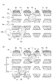
- FIG. 1 schematically shows the internal structure of a catalyst structure according to an embodiment of the present invention
- FIG. 1(a) is a perspective view (partially shown in cross section)
- FIG. 1(b) is a partially enlarged sectional view.
- 2A and 2B are partially enlarged cross-sectional views for explaining an example of the function of the catalyst structure of FIG.
- FIG. 3 schematically shows the internal structure of a catalyst structure according to a first modified example of the embodiment of the present invention, and FIG. ), and FIG. 3B is a partially enlarged sectional view.
- FIG. 4 schematically shows the internal structure of a catalyst structure according to a second modification of the embodiment of the present invention, and FIG. ), and FIG. 4B is a partially enlarged sectional view.
- FIG. 4 schematically shows the internal structure of a catalyst structure according to a second modification of the embodiment of the present invention, and FIG.
- FIG. 4B is a partially enlarged sectional view.
- FIG. 5 is a flow chart showing an example of a method for manufacturing the catalyst structure of FIG.
- FIG. 6 is a flow chart showing a modification of the method for manufacturing the catalyst structure of FIG.
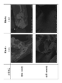
- FIG. 7 is a scanning electron microscope (SEM) photograph of the surfaces of the catalyst structures of Inventive Examples 1 and 2 at magnifications of 1,000 and 50,000.
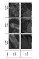
- FIG. 8 is scanning electron microscope (SEM) photographs of the surfaces of the catalyst structures of Inventive Examples 3 to 5 at magnifications of 1,000 and 50,000.
- FIG. 9 shows the quantitative values of zirconium (Zr), which is a transition metal element having redox ability, by ICP emission spectroscopy (inductively coupled plasma emission spectroscopy), and the CH4 conversion rate at the initial stage of the reaction, for the catalyst structure of the example of the present invention. [%], with the quantitative value of zirconium (Zr) on the horizontal axis and the CH4 conversion rate on the vertical axis.
- FIG. 10 shows the time from the start of the catalytic reaction (reaction time (days)) and the CH 4 conversion rate [%] for the catalyst structures of Inventive Examples 1 to 3 and 6 and Comparative Examples 1 to 3.
- Figure 2 is a graph showing the relationship, with reaction time on the horizontal axis and CH4 conversion on the vertical axis.
- FIG. 11 shows the results of H 2 -TPR measurement for the catalyst structures of Inventive Example 2 and Comparative Example 1.
- FIG. 11(b) is a diagram showing measurement results before and after evaluation
- FIG. 11(b) is a diagram showing measurement results before and after catalyst life evaluation for the catalyst structure of Comparative Example 1.
- FIG. 11(b) is a diagram showing measurement results before and after catalyst life evaluation for the catalyst structure of Comparative Example 1.
- FIG. 1 is a diagram schematically showing the configuration of a synthesis gas production catalyst structure (hereinafter sometimes simply referred to as “catalyst structure”) according to an embodiment of the present invention, and FIG. It is a perspective view (partially shown in cross section), and FIG. 1(b) is a partially enlarged sectional view. Note that the catalyst structure in FIG. 1 shows an example thereof, and the shape and dimensions of each component according to the present invention are not limited to those in FIG.
- the catalyst structure 1 is a synthesis gas production catalyst structure used in producing a synthesis gas containing carbon monoxide and hydrogen, and is composed of a zeolite compound. a first catalyst particle 20 containing an iron group element to be described later; and a second catalyst 30 containing one or more specific transition metal elements selected from transition metal elements having redox ability. and at least.
- the present inventors have previously developed a catalyst structure in which a metal catalyst is embedded in a carrier such as zeolite, and by using the catalyst structure in a dry reforming reaction, exhibit good coking resistance and It has been found that excellent catalytic activity can be maintained over a long period of time.
- the present inventors have found that oxidation of the metal catalyst by water (H 2 O) molecules produced as a by-product by the reverse shift reaction, which is a side reaction, is the main cause of the decrease in catalytic activity other than coking. , and suppresses oxidation of the metal catalyst by using catalyst particles containing an iron group element inherent in the carrier and catalyst particles containing a platinum group element such as platinum (Pt) in combination. It has been previously found that the catalyst activity can be maintained for a longer period of time because the catalyst activity can be maintained.
- catalyst particles containing a platinum group element were used in addition to catalyst particles containing an iron group element. rice field.
- the catalyst structure 1 of the present invention uses both the first catalyst particles 20 containing an iron group element inherent in the carrier and the second catalyst 30 containing a transition metal element having redox capability.
- oxidation of the first catalyst particles 20 can be suppressed.
- FIG. 11(a) shows the results of H 2 -TPR measurement before and after the catalyst life evaluation for the catalyst structure carrying the second catalyst containing a transition metal element having a redox ability of the example of the present invention.
- FIG. 11(b) is a diagram showing the results of H 2 -TPR measurement before and after catalyst life evaluation for a catalyst structure in which a second catalyst is not supported in a comparative example.
- zirconium (Zr) which is a transition metal element having a redox ability, is more likely to cause the zeolite that constitutes the support after the dry reforming reaction to collapse and fine-tune the crystal structure compared to platinum group elements such as platinum (Pt). It is also possible to suppress a decrease in catalytic activity due to a decrease in pore volume.
- the catalytic activity of the first catalyst particles 20 can be maintained for a long period of time.
- the first catalyst particles 20 are catalyst substances having catalytic activity (catalytic activity) at least when the catalyst structure 1 is used as a catalyst, and have the form of fine particles. The action of the first catalyst particles 20 and the second catalyst 30 will be described later in detail.
- the carrier 10 is composed of a zeolite-type compound and has a porous structure.
- the "zeolite type compound” in the present invention is described in Toyota Central R&D Labs. R&D Review Vol. 29, No. 2, (1994.6), it includes not only crystalline aluminum nosilicate but also zeolite-like substances including phosphate-based porous crystals having a similar structure.
- Zeolite-type compounds include, for example, zeolite (aluminosilicate), cation-exchanged zeolite, silicate compounds such as silicalite, zeolite analogues such as aluminoborates, aluminoarsenates and germanates, and molybdenum phosphate. phosphate-based zeolite-like substances, and the like.
- the zeolite-type compound is preferably a silicate compound.
- the skeletal structure of the zeolite-type compound is not particularly limited, and examples include zeolite compounds defined by the Structure Commission of the International Zeolite Association. Among them, it is preferably selected from MTW type, MFI type (ZSM-5), FER type (ferrierite), LTA type (A type), MOR type (mordenite), and LTL type (L type), MFI type zeolite is more preferable, and Silicalite-1, which does not contain aluminum (Al) element, is more preferable among MFI type zeolites.
- a zeolite-type compound is formed with a plurality of pores having a pore size corresponding to each skeleton structure. be.
- the carrier 10 has a porous structure and, as shown in FIG. 1(b), preferably has passages 11 communicating with each other by forming a plurality of holes 11a, 11a, .
- the first catalyst particles 20 contain at least an iron group element to be described later, are present in at least the passages 11 of the carrier 10 , and are preferably held in at least the passages 11 of the carrier 10 .
- the second catalyst 30 contains at least a transition metal element having redox capability and is present on at least one of the inner surface and the outer surface of the carrier 10 .
- the movement of the first catalyst particles 20 within the carrier 10 is restricted, and the aggregation of the first catalyst particles 20, 20 and the aggregation of the first catalyst particles 20 and the second catalyst 30 are effective. is prevented.
- the reduction in the effective surface area of the first catalyst particles 20 is effectively suppressed, so that the first catalyst particles 20 can be used for the dry reforming reaction in which carbon monoxide and hydrogen are generated from carbon dioxide and methane. It can act as a catalyst.
- water (H 2 O) generated in a side reaction of the dry reforming reaction is decomposed by the second catalyst 30, thereby suppressing oxidation of the first catalyst particles 20 by water.
- the catalytic activity of the first catalyst particles 20 can be maintained for a long period of time, so that the life of the catalyst structure 1 can be extended.
- the frequency of replacement of the catalyst structure 1 can be reduced, thereby significantly reducing the amount of waste of the used catalyst structure 1, thereby saving resources. be able to.
- the passage 11 is defined by the framework structure of the zeolite-type compound, and any of the one-dimensional, two-dimensional, and three-dimensional pores, and the one-dimensional, two-dimensional, and three-dimensional pores It is preferable to have an enlarged diameter portion 12 different from any of them, and at this time, at least the first catalyst particles 20 of the first catalyst particles 20 and the second catalyst 30 are present in the enlarged diameter portion 12 is preferable, and it is more preferable to be enclosed by the enlarged diameter portion 12 . As a result, the movement of the first catalyst particles 20 existing in the diameter-enlarged portion 12 within the carrier 10 is further restricted, and the separation of the first catalyst particles 20 and the aggregation of the fine particles of the first catalyst particles 20, 20 are prevented. , the agglomeration of the first catalyst particles 20 and the second catalyst 30 can be more effectively prevented.
- the inclusion refers to a state in which the first catalyst particles 20 (or the second catalyst 30) are included in the carrier 10, and the zeolite means that it is not in contact with the outside of the Further, the catalyst particles (the first catalyst particles 20 in the present embodiment) and the carrier 10 existing in the enlarged diameter portion 12 do not necessarily have to be in direct contact with each other.
- the catalyst particles may be indirectly held on the carrier 10 with another substance (for example, a surfactant or the like) interposed therebetween.
- the one-dimensional pore here means a tunnel-shaped or cage-shaped pore that forms a one-dimensional channel, or a plurality of tunnel-shaped or cage-shaped pores that form a plurality of one-dimensional channels (a plurality of one-dimensional pores). channel).
- a two-dimensional pore refers to a two-dimensional channel in which a plurality of one-dimensional channels are two-dimensionally connected
- a three-dimensional pore refers to a three-dimensional channel in which a plurality of one-dimensional channels are three-dimensionally connected. Point. Therefore, the enlarged diameter portion does not include a supercage in which pores spread as a regular structure of zeolite.
- FIG. 1B shows the case where the first catalyst particles 20 are enclosed in the expanded diameter portion 12, but the configuration is not limited to this, and the first catalyst particles 20 are partially It may be held in the passage 11 in a state of protruding outside the enlarged diameter portion 12 . Also, the first catalyst particles 20 may be partially embedded in a portion of the passage 11 other than the enlarged diameter portion 12 (for example, an inner wall portion of the passage 11), or may be held by adhesion or the like.
- the enlarged diameter portion 12 communicates with a plurality of holes 11a, 11a forming any one of the one-dimensional hole, the two-dimensional hole, and the three-dimensional hole.
- a passage different from the one-dimensional hole, the two-dimensional hole, or the three-dimensional hole is provided inside the carrier 10, so that the functions of the first catalyst particles 20 and the second catalyst 30 can be exhibited more effectively.
- the passage 11 is formed three-dimensionally inside the carrier 10 including a branching portion or a merging portion, and the enlarged diameter portion 12 is preferably provided at the branching portion or the merging portion of the passage 11. .
- the average inner diameter D F of the passages 11 formed in the carrier 10 is calculated from the average value of the short diameter and long diameter of the holes 11a constituting any one of the one-dimensional, two-dimensional and three-dimensional holes. It is 0.1 nm to 1.5 nm, preferably 0.5 nm to 0.8 nm. Further, the inner diameter D E of the expanded diameter portion 12 is, for example, 0.5 nm to 50 nm, preferably 1.1 nm to 40 nm, more preferably 1.1 nm to 3.3 nm. The inner diameter D E of the expanded diameter portion 12 depends on, for example, the pore diameter of the precursor material (A) described later and the particle size of the first catalyst particles 20 included in the expanded diameter portion 12 . The inner diameter D E of the expanded diameter portion 12 is large enough to enclose the catalyst particles 20 .
- the shape of the carrier 10 is not particularly limited, but it can be flat, for example.
- the long side dimension of the flat plate constituting the carrier 10 is preferably 1.00 ⁇ m or more, more preferably 1.00 ⁇ m or more and 50.00 ⁇ m or less, and even more preferably 1.00 ⁇ m or more and 25.00 ⁇ m or less.
- the thickness dimension of the flat plate constituting the carrier 10 is preferably 0.05 ⁇ m or more and 2.00 ⁇ m or less.
- the short side dimension along the direction perpendicular to both the long side dimension and the thickness dimension is smaller than the long side dimension of the flat plate and greater than the thickness dimension of the flat plate.
- the first catalyst particles 20 contain at least one iron-group element selected from the group consisting of nickel (Ni), iron (Fe), and cobalt (Co), and are in the form of fine particles by themselves.
- the first catalyst particles 20 are preferably nickel (Ni) particles from the viewpoint of enhancing the catalytic properties required in the first catalyst particles 20 .
- the first catalyst particles 20 may be fine metal particles containing a metal composed of one metal element, a mixture of two or more metal elements, or an alloy of at least some of them. .
- the fine metal particles are preferably composed of non-oxidized metal.
- the first catalyst particles 20 may be metal oxide fine particles composed of oxides of one or more metal elements or composite materials thereof before use. Before using the metal oxide fine particles as a catalyst, the oxides are reduced by a reduction step (step S7) described later, or exposed to a usage environment including a reducing atmosphere for a certain period of time, so that the metal fine particles can be reduced when used as a catalyst.
- the “metal” (as a material) that constitutes the metal fine particles when used as a catalyst includes a single metal composed of one metal element, a metal mixture containing two or more metal elements, or a metal mixture containing two or more metal elements.
- the term includes metal alloys, and is a general term for metals containing one or more metal elements.
- Metal fine particles and metal oxide fine particles may be held in the passage 11 in the state of primary particles, or may be held in the passage 11 in the state of secondary particles formed by agglomeration of primary particles. .
- the average particle size D C1 of the first catalyst particles 20 is preferably larger than the average inner diameter D F of the passage 11 (D C1 >D F ). Also, the average particle size D C1 of the first catalyst particles 20 is preferably equal to or less than the inner diameter D E of the enlarged diameter portion 12 (D C1 ⁇ D E ).
- D C1 ⁇ D E the inner diameter of the enlarged diameter portion 12
- the average particle diameter D C1 of the first catalyst particles 20 is preferably in the range of 1.0 nm or more and 13.0 nm or less, more preferably in the range of 1.0 nm or more and 9.0 nm or less, and still more preferably 1 0 nm or more and 4.5 nm or less.
- the average particle diameter D C1 of the first catalyst particles 20 is within this range, it becomes difficult for carbon to polymerize on the first catalyst particles 20, and coking, which will be described later, is less likely to occur, thereby further improving the catalytic activity. can be made
- the dimension ratio (D C1 /D F ) of the average particle diameter D C of the first catalyst particles 20 to the average inner diameter D F of the passage 11 is preferably in the range of more than 1 and 130 or less, more preferably 1. It is in the range of 1 to 90, more preferably in the range of 1.1 to 45, and further preferably in the range of 1.4 to 6.3.
- the average particle diameter D C1 of the first catalyst particles 20 is measured by measuring the cross section of the catalyst structure 1 by small angle X-ray scattering (SAXS), and fitting the obtained SAXS data with a spherical model by the Guinier approximation method. A method can be mentioned. At this time, the dispersed state of the first catalyst particles 20 in the catalyst structure 1 can also be obtained.
- SAXS small angle X-ray scattering
- SPring-8 beamline BL19B2 can be used for measurement by SAXS.
- the content of the first catalyst particles 20 in the catalyst structure 1 is a quantitative value by ICP emission spectroscopy (high frequency inductively coupled plasma emission spectroscopy) from the viewpoint of obtaining desired catalyst properties and making coking more difficult to occur. It is preferably contained in the range of 0.50% by mass to 3.50% by mass in total with respect to the body 1, and is contained in the range of 0.50% by mass to 2.50% by mass. More preferably, the content is in the range of 0.50% by mass or more and 1.50% by mass or less. If the content of the first catalyst particles 20 is less than 0.50% by mass, there is a possibility that the activity as a catalyst for dry reforming will be insufficient, such as low activity.
- the carrier 10 tends to carry too many first catalyst particles 20 and the strength of the carrier 10 decreases.
- the content of the first catalyst particles 20 obtained by ICP emission spectroscopy is represented by, for example, ⁇ (mass of iron group element)/(mass of all elements in catalyst structure 1) ⁇ 100.
- the first catalyst particles 20 have the effect of promoting the reaction of converting carbon dioxide and methane contained in the source gas into reaction gases containing carbon monoxide and hydrogen in dry reforming.
- dry reforming has a higher carbon content in the raw material than steam reforming, which reacts methane and steam, so it is easier to deposit carbon on the surface of the catalyst. Therefore, in dry reforming, a problem that catalytic activity is lowered due to deposition of carbon and a coking problem that the deposited carbon clogs the reaction tube holding the catalyst structure 1 are likely to occur.
- nickel (Ni), iron (Fe), and cobalt (Co) nickel (Ni), which is known to have high activity, has a large amount of reaction, which inevitably causes coking. likely to occur.
- iron (Fe) and cobalt (Co) have low activity, the amount of coking is smaller than that of nickel (Ni).
- the catalyst structure 1 using an iron group element is required to make coking difficult in exchange for enhancing activity. Therefore, in the catalyst structure 1 of the present invention, by using together the first catalyst particles 20 containing an iron group element and the second catalyst 30 containing a transition metal element having redox ability, the activity is enhanced and , making caulking unlikely.
- the second catalyst 30 contains a specific transition metal element selected from transition metal elements having redox (abbreviation of reduction oxidation reaction) ability, and is present on at least one of the inner surface and the outer surface of the carrier 10 .
- the second catalyst 30 can suppress oxidation of the first catalyst particles 20 by decomposing water (H 2 O) molecules by-produced by the reverse shift reaction, which is a side reaction in the dry reforming reaction. can maintain the catalytic activity of the first catalyst particles 20 for a long time.
- the second catalyst 30 contains one or more specific transition metal elements having redox ability, among which zirconium (Zr), vanadium (V), chromium (Cr), manganese (Mn), cobalt ( Co), copper (Cu), zinc (Zn), molybdenum (Mo), and titanium (Ti), and more preferably zirconium (Zr).
- the second catalyst 30 preferably contains these specific transition metal elements, alloys of at least a part thereof, and oxides of these specific transition metal elements.
- the shape of the second catalyst 30 is not particularly limited, and may have, for example, a particulate shape or a film-like shape formed by aggregating particles.
- the shape of the second catalyst 30 is preferably at least one of film-like and particulate-like.
- the shape of the second catalyst 30 is preferably particulate.
- both the first catalyst particles 20 and the second catalyst 30 are preferably fine metal particles or fine metal oxide particles.
- the average particle diameter D C2 of the second catalyst 30 inside the carrier is preferably larger than the average inner diameter D F of the passage 11 (D C2 >D F ). Also, the average particle diameter D C2 of the second catalyst 30 present inside the carrier is preferably equal to or less than the inner diameter D E of the enlarged diameter portion 12 (D C2 ⁇ D E ). By setting the average particle diameter D C2 of the second catalyst 30 within this range, movement of the second catalyst 30 within the carrier 10 of the second catalyst 30 is restricted.
- the second catalyst 30 receives an external force from the fluid, the movement of the second catalyst 30 within the carrier 10 is suppressed, and the second catalyst 30 dispersedly arranged on the carrier 10 is prevented from moving to the second catalyst 30 . Aggregation due to contact with the catalyst 30 and the first catalyst particles 20 can be effectively prevented.
- the content of the second catalyst 30 in the catalyst structure 1 is determined by ICP emission spectroscopy (high frequency inductively coupled plasma emission spectroscopy), it is preferably 0.85% by mass or more in total with respect to the catalyst structure 1 .
- the content of the second catalyst 30 is preferably less than 12.00% by mass in total as a quantitative value by ICP emission spectroscopy.
- the content of the second catalyst 30 in the catalyst structure 1 obtained by ICP emission spectroscopy is, for example, ⁇ (mass of the specific transition metal element contained in the second catalyst 30)/(all elements in the catalyst structure 1 mass) ⁇ 100.
- the catalyst structure 1 may contain other elements that are different from both the iron group elements and the specific transition metal elements.
- Other elements include one or more metal elements selected from the group consisting of metals of Groups 1, 2 and 12 of the periodic table. Among them, it is preferable to contain one or more metal elements selected from the group consisting of potassium (K), magnesium (Mg), manganese (Mn) and zinc (Zn) as other elements.
- K potassium
- Mg magnesium
- Mn manganese
- Zn zinc
- the content of other elements is 5% by mass or less with respect to the catalyst structure 1 as a quantitative value by ICP emission spectroscopy. is preferably
- the catalyst structure 1 has a platinum group selected from the group consisting of platinum (Pt), palladium (Pd), rhodium (Rh) and ruthenium (Ru). It is preferable to further contain a third catalyst (not shown) containing an element.
- the content of the platinum group element constituting the third catalyst in the catalyst structure 1 is preferably 0.02% by mass or more, more preferably 0.10% by mass or more, relative to the catalyst structure 1. is more preferable, and 0.40% by mass or more is even more preferable.
- the upper limit of the content of the platinum group element constituting the third catalyst in the catalyst structure 1 is not particularly limited. good too.
- a third catalyst can be present on one or both of the inner and outer surfaces of the carrier 10 . In particular, the third catalyst is preferably present on the outer surface of carrier 10 .
- the material cost of the catalyst structure 1 using platinum group elements is reduced.
- the catalyst structure 1 preferably does not contain platinum group elements as other elements.
- the catalyst structure 1 is present on at least one of the carrier 10 having a porous structure, the first catalyst particles 20 that are present in the carrier 10 and contain an iron group element, and the inner and outer surfaces of the carrier, and a second catalyst 30 containing a transition metal element having redox capability.
- the first catalyst particles 20 contained in the carrier come into contact with a fluid containing methane and carbon dioxide, whereby the first catalyst particles 20 exhibit catalytic ability in the chemical reaction of dry reforming. do.
- the fluid in contact with the outer surface 10a of the catalyst structure 1 flows into the carrier 10 through the holes 11a formed in the outer surface 10a, is guided into the passage 11, and moves through the passage 11. , exits the catalyst structure 1 through another hole 11a.
- Catalytic reaction by the first catalyst particles 20 occurs when the fluid comes into contact with the first catalyst particles 20 present in the passage 11 on the path along which the fluid moves through the passage 11 .
- the catalyst structure 1 has a molecular sieving ability due to the porous structure of the carrier.
- the molecular sieving ability of the catalyst structure 1 will be described with reference to FIG.
- the methane-containing gas is a mixed gas containing methane and a gas other than methane.
- the methane-containing gas and carbon dioxide may be brought into contact with the catalyst structure 1 in order or may be brought into contact simultaneously.
- molecules 15 a having a size equal to or less than the pore diameter of the hole 11 a in other words, the inner diameter of the passage 11 or less can enter the carrier 10 .
- molecules 15b having a size exceeding the pore diameter of pore 11a cannot penetrate into carrier 10 . In this way, when the fluid contains multiple types of compounds, the reaction of the compounds that cannot penetrate into the carrier 10 is regulated, and the compounds that can penetrate into the carrier 10 can react.
- the first catalyst particles 20 are enclosed in the enlarged diameter portion 12 of the passage 11.
- the average particle diameter D C1 of the first catalyst particles 20 is larger than the average inner diameter D F of the passage 11 and smaller than the inner diameter D E of the expanded diameter portion 12 (D F ⁇ D C1 ⁇ D E )
- a small passage 13 is formed between the first catalyst particle 20 and the enlarged diameter portion 12 . Therefore, as indicated by arrows in FIG. Since the first catalyst particles 20 are surrounded by the enlarged diameter portion 12 , movement within the carrier 10 is restricted. This prevents aggregation of the fine particles of the first catalyst particles 20 in the carrier 10 . As a result, a large contact area between the first catalyst particles 20 and the fluid can be stably maintained.
- the catalyst structure 1 is present on at least one of the inner surface and the outer surface of the support and contains a transition metal element having redox capability, and the second catalyst 30 causes the reverse shift reaction, which is a side reaction of the dry reforming reaction. Since the water (H 2 O) generated as a by-product can be decomposed, it is considered possible to suppress a decrease in catalytic activity due to oxidation of the first catalyst particles 20 containing an iron group element.
- a synthesis gas containing carbon monoxide and hydrogen can be produced using a methane-containing gas and carbon dioxide as raw materials.
- This catalytic reaction dry reforming reaction
- This catalytic reaction is performed at a high temperature of, for example, 700° C. or higher, but since the first catalyst particles 20 are present in the carrier 10, they are not easily affected by heating.
- the CH 4 conversion rate (initial CH 4 conversion rate) 1 hour after the start of supplying the raw material gas is preferably 50% or more, preferably 70%. It is more preferable to be above.
- catalytic activity can be enhanced when the catalyst structure for syngas production is used in a dry reforming reaction.
- FIG. 3 schematically shows the internal structure of a catalyst structure according to a first modified example of the embodiment of the present invention, and FIG. ), and FIG. 3B is a partially enlarged sectional view.
- the same components as those of the catalyst structure 1 of FIG. 1 are denoted by the same reference numerals, and descriptions thereof are omitted or simplified, and differences are mainly described.
- the catalyst structure 1 of FIG. 1 shows the case where the second catalyst 30 is present on the outer surface 10a of the carrier 10, it is not limited to this configuration, and for example, the catalyst structure 1A shown in FIG. As such, the second catalyst 30A is present inside the carrier 10 and is preferably carried in at least the passages 11 of the carrier 10 . That is, both the first catalyst particles 20 and the second catalyst 30A may exist in the passages 11 of the carrier 10 in the catalyst structure 1A.
- the passages 11 are defined by the framework structure of the zeolite-type compound, and any one of the one-dimensional, two-dimensional and three-dimensional pores.
- the enlarged diameter portion 12 is different from both, it is preferable that both the first catalyst particles 20 and the second catalyst 30 exist in the enlarged diameter portion 12 and are enclosed in the enlarged diameter portion 12. more preferably.
- both the average particle diameter D C1 of the first catalyst particles 20 and the average particle diameter D C2 of the second catalyst 30 existing inside the carrier 10 are larger than the average inner diameter D F of the passage 11 . is preferred (D C1 >D F , D C2 >D F ).
- both the average particle diameter D C1 of the first catalyst particles 20 and the average particle diameter D C2 of the second catalyst 30 existing inside the carrier 10 are equal to or less than the inner diameter D E of the expanded diameter portion 12 . is preferred (D C1 ⁇ D E , D C2 ⁇ D E ).
- the first catalyst existing inside the carrier 10 Movement of the particles 20 and the second catalyst 30 within the carrier 10 is restricted. Therefore, aggregation of the first catalyst particles 20 and the second catalyst 30 dispersed on the carrier 10 can be effectively prevented, and as a result, the service life of the catalyst structure 1A can be further extended.
- the second catalyst 30 and the carrier 10 do not necessarily have to be in direct contact with each other. In this state, the second catalyst 30 may indirectly exist on the carrier 10 .
- FIG. 4 schematically shows the internal structure of a catalyst structure according to a second modification of the embodiment of the present invention, and FIG. ), and FIG. 4B is a partially enlarged sectional view.
- the same components as those of the catalyst structure 1 of FIG. 1 are denoted by the same reference numerals, and descriptions thereof are omitted or simplified, and differences are mainly described.
- the catalyst structure 1 in FIG. 1 shows a case in which the first catalyst particles 20 and the second catalyst 30 are provided, it is not limited to this configuration.
- the catalyst structure 1B in FIG. in addition to the first catalyst particles 20 and the second catalyst 30 described above, at least one other catalyst 40 held on the outer surface 10a of the carrier 10 may be further provided.
- Other catalysts 40 include those containing one or more iron group elements selected from the group consisting of nickel (Ni), iron (Fe) and cobalt (Co).
- the shape of the other catalyst 40 is not particularly limited, and examples thereof include at least one of a film shape and a particulate shape.
- the other catalyst 40 exhibits catalytic ability in the dry reforming chemical reaction together with the first catalyst particles 20, and can further promote the dry reforming reaction.
- the total content of the first catalyst particles 20 and the second catalyst 30 present inside the carrier 10 is greater than the content of the other catalysts 40 held on the outer surface 10a of the carrier 10. preferable.
- the catalytic ability of the first catalyst particles 20 held inside the carrier 10 and the second catalyst 30 present in the carrier 10 becomes dominant, so that the first catalyst particles 20 and the second catalyst 30 are stably It is possible to exhibit the catalytic ability by
- the catalyst structure 1B has the second catalyst 30 on the outer surface 10a of the carrier 10 . That is, it is preferred that the second catalyst 30 and the other catalyst 40 are present on the outer surface 10a of the carrier 10 . As a result, even when another catalyst 40 is provided on the outer surface 10a of the carrier 10, when dry reforming is performed, by-products are produced in the vicinity of the other catalyst 40 held on the outer surface 10a of the carrier 10. Since the water (H 2 O) molecules that have formed can be decomposed, the service life of the catalyst structure 1B can be further extended.
- FIG. 5 is a flow chart showing an example of the method for producing the catalyst structure of the present invention. An example of a method for manufacturing a catalyst structure will be described below.
- Step S1 preparation process
- a precursor material (A) having pores of 13.0 nm or less for obtaining a carrier having a porous structure composed of a zeolite-type compound is prepared.
- the precursor material (A) is preferably a regular mesoporous material, and can be appropriately selected according to the type (composition) of the zeolite compound that constitutes the carrier of the catalyst structure.
- the regular mesoporous material has a pore diameter of 13.0 nm or less, more preferably 1.0 nm or more and 13.0 nm. It is preferable that the pores below be a compound consisting of a Si—O skeleton that has a uniform size and is regularly developed in one, two, or three dimensions.
- Such regular mesoporous materials can be obtained as various synthetic products depending on the synthesis conditions. 16, MCM-41 and the like, among which MCM-41 is preferred.
- the pore diameter of SBA-1 is 10 nm to 30 nm
- the pore diameter of SBA-15 is 6 nm to 10 nm
- the pore diameter of SBA-16 is 6 nm
- the pore diameter of KIT-6 is 9 nm
- the pore diameter of FSM-16 is 3 nm. ⁇ 5 nm
- the pore size of MCM-41 is between 1 nm and 10 nm.
- ordered mesoporous materials include mesoporous silica, mesoporous aluminosilicate, and mesoporous metallosilicate.
- the precursor material (A) may be either a commercial product or a synthetic product. Synthesis of the precursor material (A) can be carried out by a known method for synthesizing ordered mesoporous materials. For example, a mixed solution containing raw materials containing constituent elements of the precursor material (A) and a templating agent for defining the structure of the precursor material (A) is prepared, and the pH is adjusted as necessary. , perform hydrothermal treatment (hydrothermal synthesis). After that, the precipitate (product) obtained by the hydrothermal treatment is recovered (for example, filtered), washed and dried as necessary, and further calcined to obtain a powdery ordered mesoporous material. A precursor material (A) is obtained.
- the raw material to be included in the mixed solution is selected according to the type of carrier, and examples thereof include silica agents such as tetraethoxysilane (TEOS), fumed silica, and quartz sand.
- a solvent for the mixed solution for example, water, an organic solvent such as alcohol, or a mixed solvent thereof can be used.
- the templating agent various surfactants, block copolymers, and the like can be used, and it is preferable to select them according to the type of the ordered mesoporous material synthesized, for example, when producing MCM-41. is preferably a surfactant such as hexadecyltrimethylammonium bromide or tetraethylammonium hydroxide.
- the hydrothermal treatment can be carried out, for example, in a closed vessel under conditions of 80° C. to 800° C., 5 hours to 240 hours, and 0 to 2000 kPa.
- the calcination treatment can be performed, for example, in the air at 350° C. to 850° C. for 2 hours to 30 hours.
- Step S2 first impregnation step
- the prepared precursor material (A) is impregnated with an iron group element-containing solution containing at least an iron group element to obtain a precursor material (B).
- the iron group element-containing solution contains at least one iron group element selected from the group consisting of nickel (Ni), iron (Fe) and cobalt (Co).
- the iron group element-containing solution may be a solution containing a metal component (for example, metal ion) corresponding to the iron group element (M 1 ) constituting the first catalyst particles of the catalyst structure. It can be prepared by dissolving a metal salt containing an iron group element (M 1 ) in a solvent.
- metal salts include metal salts such as chlorides, hydroxides, oxides, sulfates and nitrates, among which chlorides and nitrates are preferred.
- the solvent for example, water, an organic solvent such as alcohol, or a mixed solvent thereof can be used.
- the method for impregnating the precursor material (A) with the iron group element-containing solution is not particularly limited, but for example, the powdery precursor material (A) is stirred before the first firing step (step S3) described later
- a surfactant it is preferable to add a surfactant.
- Such an additive has the function of covering the outer surface of the precursor material (A), and suppresses the iron group element-containing solution added later from adhering to the outer surface of the precursor material (A). , the iron group element-containing solution is believed to be more likely to penetrate into the pores of the precursor material (A).
- nonionic surfactants such as polyoxyethylene oleyl ether, polyoxyethylene alkyl ether, and polyoxyethylene alkylphenyl ether. Since these surfactants have a large molecular size and cannot penetrate into the pores of the precursor material (A), they do not adhere to the inside of the pores, and the iron group element-containing solution penetrates into the pores. is not considered to prevent As a method for adding the nonionic surfactant, for example, before the first baking step (step S3) described later, the nonionic surfactant is added to the precursor material (A) in an amount of 50% to 500% by mass. % by mass is preferred.
- the amount of the nonionic surfactant added to the precursor material (A) is less than 50% by mass, the above suppressing effect is difficult to develop, and the nonionic surfactant is added to the precursor material (A) in an amount of 500% by mass. Adding more than % by mass is not preferable because the viscosity increases too much. Therefore, the amount of the nonionic surfactant added to the precursor material (A) is set within the above range.
- the addition amount of the iron group element-containing solution to be added to the precursor material (A) is the amount of the iron group element (M 1 ) contained in the iron group element-containing solution to be impregnated into the precursor material (A) (i.e. , the amount of the iron group element (M 1 ) to be incorporated in the precursor material (B)), and is preferably adjusted as appropriate.
- the amount of the iron group element-containing solution added to the precursor material (A) is the ratio (atomic ratio Si/M 1 ), preferably 10 to 1000, more preferably 50 to 200.
- the iron group element to be added to the precursor material (A) is set to 50 to 200 in terms of the atomic ratio Si/M 1 , so that the iron group element (M 1 ) as the first catalyst particles is quantitatively determined by ICP emission spectroscopy, and the catalyst structure It can be contained in the range of 0.50% by mass or more and 3.50% by mass or less in total with respect to the body.
- the amount of the iron group element (M 1 ) present inside the pores depends on various factors such as the metal concentration of the iron group element-containing solution, the presence or absence of the above additives, and other temperature and pressure. If the conditions are the same, it is roughly proportional to the addition amount of the iron group element-containing solution added to the precursor material (A). In addition, the amount of the iron group element (M 1 ) inherent in the precursor material (B) is proportional to the amount of the iron group element (M 1 ) constituting the first catalyst particles inherent in the support of the catalyst structure. be.
- the addition amount of the iron group element-containing solution added to the precursor material (A) within the above range the inside of the pores of the precursor material (A) can be sufficiently impregnated with the iron group element-containing solution. and thus the amount of the first catalyst particles embedded in the support of the catalyst structure can be adjusted.
- a cleaning treatment may be performed as necessary.
- the cleaning solution water, an organic solvent such as alcohol, or a mixed solution thereof can be used.
- the precursor material (A) is impregnated with the iron group element-containing solution, washed as necessary, and then dried. Drying treatments include natural drying for about one night and high-temperature drying at 150° C. or less.
- the precursor material (A) becomes ordered mesomorphic. Sufficient drying is preferable because the skeleton structure of the porous material may be destroyed.
- Step S3 first baking step
- the precursor material (B) obtained by impregnating the precursor material (A) with the iron group element-containing solution for obtaining a porous structure carrier composed of a zeolite-type compound is calcined to obtain the precursor material ( C) is obtained.
- the firing treatment in the first firing step (step S3) is preferably performed, for example, in the air, within a predetermined temperature range, under processing conditions of 2 to 30 hours.
- the predetermined temperature range for the firing treatment is preferably 350°C to 850°C, more preferably 500°C to 850°C.
- Step S4 hydrothermal treatment step
- the precursor material (C) obtained by baking the precursor material (B) is hydrothermally treated to obtain the precursor material (D). More specifically, a mixed solution is prepared by mixing the precursor material (C) and a structure-directing agent, and the precursor material (C) obtained by baking the precursor material (B) is subjected to hydrothermal treatment. to obtain the precursor material (D).
- the structure-directing agent is a templating agent for defining the skeleton structure of the carrier of the catalyst structure, and for example, a surfactant can be used.
- the structure-directing agent is preferably selected according to the skeleton structure of the carrier of the catalyst structure. is preferred.
- the precursor material (C) and the structure-directing agent may be mixed during the hydrothermal treatment step (step S4) or before the hydrothermal treatment step (step S4).
- the method for preparing the mixed solution is not particularly limited, and the precursor material (C), the structure-directing agent, and the solvent may be mixed at the same time, or the precursor material (C) and the structure-directing agent may be mixed together in the solvent.
- Each dispersion solution may be mixed after dispersing each of the agents into individual solutions.
- the solvent for example, water, an organic solvent such as alcohol, a mixed solvent thereof, or the like can be used.
- the mixed solution is adjusted in pH with an acid or a base before the hydrothermal treatment.
- the hydrothermal treatment can be carried out by a known method. For example, it is preferably carried out in a closed container under the treatment conditions of 80° C. to 200° C., 5 hours to 100 hours, and 0 to 2000 kPa. Also, the hydrothermal treatment is preferably performed in a basic atmosphere.
- the reaction mechanism here is not necessarily clear, by performing hydrothermal treatment using the precursor material (C) as a raw material, the skeletal structure of the precursor material (C) as an ordered mesoporous substance gradually collapses. While the position of the first catalyst particles inside the pores of the precursor material (C) is generally maintained, the action of the structure-directing agent forms a new skeleton structure (porous structure) as a support for the catalyst structure. be done.
- the precursor material (D) thus obtained comprises a support having a porous structure, and first catalyst particles that are inherent in the support and contain at least the above iron group element, and further, the support has the porous structure
- the plurality of pores have passages communicating with each other, and the first catalyst particles are at least partially present in the passages of the carrier.
- a mixed solution is prepared by mixing the precursor material (C) and the structure-directing agent, and the precursor material (C) is hydrothermally treated.
- the precursor material (C) may be hydrothermally treated without mixing the precursor material (C) and the structure-directing agent.
- the precipitate obtained after the hydrothermal treatment is preferably collected (for example, filtered) and then washed, dried, and calcined as necessary to obtain the precursor material (D).
- the cleaning solution water, an organic solvent such as alcohol, or a mixed solution thereof can be used. Drying treatments include natural drying for about one night and high-temperature drying at 150° C. or less. It should be noted that if the calcination treatment is performed in a state in which a large amount of water remains in the precipitate, there is a risk that the skeletal structure as a carrier of the catalyst structure may be broken, so it is preferable to dry the precipitate sufficiently. Further, the calcination treatment can be performed, for example, in the air under the treatment conditions of 350° C. to 850° C. for 2 hours to 30 hours. By such a calcination treatment, the structure-directing agent adhering to the precipitate after the hydrothermal treatment is burned off.
- Step S5 second impregnation step
- the precursor material (D) obtained by hydrothermally treating the precursor material (C) contains a specific transition metal element containing at least a specific transition metal element selected from transition metal elements having redox ability. impregnate the solution;
- the specific transition metal element-containing solution may be a solution containing a transition metal element having redox ability that constitutes the second catalyst, and can be prepared, for example, by dissolving a metal salt containing zirconium (Zr) in a solvent.
- metal salts include metal salts such as chlorides, hydroxides, oxides, sulfates and nitrates, among which chlorides and nitrates are preferred.
- the solvent for example, water, an organic solvent such as alcohol, or a mixed solvent thereof can be used.
- the method for impregnating the precursor material (D) with the solution containing the specific transition metal element is not particularly limited. It is preferable to add the specific transition metal element-containing solution to the precursor material (D) little by little in multiple batches while stirring.
- the precursor material (D) is A surfactant may be added as an additive in advance before adding the specific transition metal element-containing solution.
- the addition amount of the specific transition metal element-containing solution to be added to the precursor material (D) takes into account the amount of the specific transition metal element contained in the specific transition metal element-containing solution to be impregnated into the precursor material (D). It is preferable to adjust accordingly. For example, when the precursor material (D) is impregnated with the specific transition metal element-containing solution before the second firing step (step S6) described later, the specific transition metal element-containing solution added to the precursor material (D) The amount added is the percentage of the mass of the specific transition metal element contained in the solution containing the specific transition metal element with respect to the total mass of the precursor material (D) and the specific transition metal element to be added, and is preferably 1% by mass to 15% by mass.
- the specific transition metal element-containing solution is 1% by mass as a percentage of the mass of the specific transition metal element contained in the specific transition metal element-containing solution with respect to the total mass of the precursor material (D) and the specific transition metal element to be added.
- the specific transition metal element contained in the obtained catalyst structure 1 is a quantitative value by ICP emission spectroscopy (high frequency inductively coupled plasma emission spectroscopy), and the total amount of It can be contained in the range of 0.85% by mass or more and less than 12.00% by mass.
- a cleaning treatment may be performed as necessary.
- the precursor material (D) is impregnated with the solution containing the specific transition metal element, washed as necessary, and then dried.
- the conditions for the washing treatment and the drying treatment can be, for example, the same as the conditions for the washing treatment and the drying treatment after impregnation with the iron group element-containing solution.
- Step S6 second firing step
- the precursor material (D) impregnated with the specific transition metal element-containing solution is calcined to obtain a catalyst structure.
- the calcination treatment for the precursor material (D) is preferably carried out, for example, in air, within a predetermined temperature range, under treatment conditions of 2 to 30 hours.
- the predetermined temperature range for this firing treatment is preferably 350°C to 850°C, more preferably 500°C to 850°C.
- the specific transition metal element component impregnated inside the ordered mesoporous material or adhered to the outer surface grows crystals to form the second catalyst.
- the catalyst structure thus obtained comprises a carrier having a porous structure, first catalyst particles containing at least an iron group element present in the carrier, and a specific transition existing on at least one of the inner surface and the outer surface of the carrier.
- a second catalyst containing at least a metal element, the carrier having passages in which a plurality of pores communicate with each other due to its porous structure, and at least a portion of the first catalyst particles existing in the passages of the carrier. ing.
- the precursor material (D) before performing the second impregnation step (step S5) and the second firing step (step S6), or after performing the second impregnation step (step S5) and the second firing step (step S6) may be impregnated with a solution containing another element different from both the iron group element and the specific transition metal element, and fired.
- a solution containing other elements a solution containing a platinum group element can be mentioned.
- Conditions for impregnating and calcining the solution containing other elements may be, for example, the same conditions as those in the second impregnating step (step S5) and the second calcining step (step S6) described above.
- Step S7 reduction step
- the method for producing a catalyst structure of the present embodiment preferably includes a reduction step (step S7) in which the precursor material (D) calcined in the second calcination step (step S6) is subjected to a reduction treatment.
- a reduction step step S7 in which the precursor material (D) calcined in the second calcination step (step S6) is subjected to a reduction treatment.
- the catalyst structure of the present invention containing at least one metal of Co, Fe, and Ni as the iron group element (M 1 ), after the first impregnation step (step S2) of impregnating with the iron group element-containing solution
- the heat treatment in the steps (steps S3 to S6), particularly the heat treatment in the hydrothermal treatment step (step S4) oxidizes the iron group elements.
- metal oxide fine particles mainly composed of oxides of iron group elements are present as catalyst particles in the support of the catalyst structure after the second firing step (step S6). Therefore, in order to obtain a catalyst structure in which the first catalyst particles containing an iron group element are present as fine metal particles, hydrogen gas or the like is added to the precursor material (D) fired in the second firing step (step S6). It is preferable to perform the reduction treatment in a reducing gas atmosphere of . By performing the reduction treatment, the metal oxide fine particles inherent in the carrier are reduced to form metal fine particles corresponding to the metal elements constituting the metal oxide fine particles. As a result, it is possible to obtain a catalyst structure in which the metal fine particles are present in the carrier as the first catalyst particles.
- the reduction step (step S7) may be performed as necessary.
- the environment in which the catalyst structure is used can become a reducing atmosphere at least temporarily, the metal oxide fine particles are reduced by exposure to the use environment including the reducing atmosphere for a certain period of time.
- a similar catalyst structure is obtained. Therefore, in this case, the precursor of the catalyst structure described above, wherein the precursor material of at least the first catalyst particles of the first catalyst particles and the second catalyst is metal oxide fine particles, It can also be used as it is.
- FIG. 6 is a flow chart showing a modification of the method for producing a catalyst structure of the present invention.
- the same reference numerals are assigned to the same components as in the method for manufacturing a catalyst structure shown in the flow chart of FIG.
- the first impregnation step (step S2) of impregnating the precursor material (A) with the iron group element-containing solution (step S2), and the precursor material impregnated with the iron group element-containing solution A first firing step (step S3) of firing B), a hydrothermal treatment step (step S4) of hydrothermally treating the precursor material (C) obtained by firing the precursor material (B), and a precursor material
- a first impregnation step (step S2) in which the precursor material (A) is impregnated with a metal-containing solution containing an iron group element-containing solution and a specific transition metal element-containing solution, and a metal-containing solution A first firing step (step S3) of firing the precursor material (B) impregnated with, and a hydrothermal treatment step of hydrothermally treating the precursor material (C) obtained by firing the precursor material (B) ( It is also preferable to fabricate the catalyst structure 1 by performing step S4).
- the first catalyst particles containing the iron group element and the second catalyst containing the specific transition metal element can be simultaneously formed inside the carrier 10, so that the catalyst structure 1 can be formed more efficiently. can be made.
- Step S2 first impregnation step
- the precursor material (A) having pores of 13.0 nm or less for obtaining a porous structure carrier composed of a zeolite-type compound, a metal containing an iron group element and a specific transition metal element
- the containing solution is impregnated to obtain a precursor material (B).
- the iron group element-containing solution contains at least one iron group element selected from the group consisting of nickel (Ni), iron (Fe) and cobalt (Co).
- the specific transition metal element-containing solution contains at least a specific transition metal element selected from one or more transition metal elements having redox capability.
- the metal-containing solution may be a solution containing at least a metal component corresponding to the iron group element (M 1 ) that constitutes the first catalyst particles and a specific transition metal element that constitutes the second catalyst. It can be prepared by dissolving a metal salt containing a group element (M 1 ) and a metal salt containing a specific transition metal element in a solvent.
- the metal-containing solution may further contain other elements such as platinum group elements.
- the method for impregnating the precursor material (A) with the metal-containing solution is not particularly limited. It is preferable to add the metal-containing solution to the precursor material (A) little by little in multiple batches. In addition, from the viewpoint of making it easier for the metal-containing solution to penetrate into the pores of the precursor material (A), a surfactant is added as an additive to the precursor material (A) in advance before adding the metal-containing solution. It is preferable to add.
- Such an additive has the function of coating the outer surface of the precursor material (A), suppresses the metal-containing solution added thereafter from adhering to the outer surface of the precursor material (A), It is believed that the contained solution is more likely to penetrate into the pores of the precursor material (A).
- the concentration and addition amount of the metal - containing solution to be added to the precursor material ( A ) are determined by (that is, the amount of the iron group element (M 1 ) and the specific transition metal element (M 2 ) to be contained in the precursor material (B)) is preferably taken into consideration and adjusted as appropriate.
- the addition amount of the metal-containing solution added to the precursor material (A) is In terms of the ratio of silicon (Si) constituting the precursor material (A) to the iron group element (M 1 ) contained in the metal-containing solution added to the material (A) (atomic ratio Si/M 1 ) , preferably 10-1000, more preferably 50-200.
- iron as the first catalyst particles can be contained in a total amount of 0.50% by mass or more and 3.50% by mass or less based on the catalyst structure as a quantitative value by ICP emission spectroscopy.
- the concentration and amount of the metal-containing solution added to the precursor material (A) are It is preferable to adjust the percentage of the mass of the specific transition metal element to the total mass of the material (A) and the specific transition metal element to be added in the range of 1% by mass or more and 15% by mass or less.
- the concentration and addition amount of the metal-containing solution to be added to the precursor material (A) are expressed as a percentage of the mass of the specific transition metal element with respect to the total mass of the precursor material (A) and the specific transition metal element to be added,
- the content of the specific transition metal element in the obtained catalyst structure 1 is in the range of 1% by mass or more and 15% by mass or less, the total content of the specific transition metal element is 0.85% by mass as a quantitative value by ICP emission spectroscopy. It can be in the range of not less than 12.00% by mass.
- the amount of the iron group element (M 1 ) present inside the pores depends on various conditions such as the metal concentration of the metal-containing solution, the presence or absence of the above additives, and other temperature and pressure. If it is the same, it is roughly proportional to the amount of the metal-containing solution added to the precursor material (A). In addition, the amount of the iron group element (M 1 ) inherent in the precursor material (B) is proportional to the amount of the iron group element (M 1 ) constituting the first catalyst particles inherent in the support of the catalyst structure. be.
- the addition amount of the metal-containing solution to be added to the precursor material (A) within the above range, the inside of the pores of the precursor material (A) can be sufficiently impregnated with the metal-containing solution. , the amount of the first catalyst particles and the second catalyst contained in the carrier of the catalyst structure can be adjusted.
- a cleaning treatment may be performed as necessary. Moreover, it is preferable that the precursor material (A) is impregnated with the metal-containing solution, washed as necessary, and then dried.
- Step S3 first baking step
- the precursor material (B) in which the precursor material (A) is impregnated with the metal-containing solution containing the iron group element and the specific transition metal element is fired to obtain the precursor material (C).
- the firing treatment in the first firing step (step S3) is preferably performed, for example, in the air, within a predetermined temperature range, under processing conditions of 2 to 30 hours.
- the predetermined temperature range for the firing treatment is preferably 350°C to 850°C, more preferably 500°C to 850°C.
- Step S4 hydrothermal treatment step
- the precursor material (C) obtained by calcining the precursor material (B) is hydrothermally treated to obtain a catalyst structure. More specifically, a mixed solution is prepared by mixing the precursor material (C) and a structure-directing agent, and the precursor material (C) obtained by baking the precursor material (B) is subjected to hydrothermal treatment. to obtain a catalyst structure.
- the hydrothermal treatment can be carried out by a known method. For example, it is preferably carried out in a closed container under the treatment conditions of 80° C. to 200° C., 5 hours to 100 hours, and 0 to 2000 kPa. Also, the hydrothermal treatment is preferably performed in a basic atmosphere.
- the catalyst structure obtained in this manner includes a carrier having a porous structure, first catalyst particles inherent in the carrier and containing at least the above iron group element, and first catalyst particles containing at least the above specific transition metal element. Further, the porous structure of the carrier has passages in which a plurality of pores communicate with each other, and at least a portion of the first catalyst particles and the second catalyst are present in the passages of the carrier.
- Step S7 reduction step
- the method for manufacturing a catalyst structure of the present embodiment preferably includes a reduction step (step S7) in which the catalyst structure obtained in the hydrothermal treatment step (step S4) is subjected to a reduction treatment.
- the reduction treatment By performing the reduction treatment, the metal oxide fine particles inherent in the carrier are reduced to form metal fine particles corresponding to the metal elements constituting the metal oxide fine particles. As a result, it is possible to obtain a catalyst structure in which the metal fine particles are present in the carrier as the first catalyst particles.
- step S7 may be performed as necessary.
- the environment in which the catalyst structure is used can become a reducing atmosphere at least temporarily, the metal oxide fine particles are reduced by exposure to the use environment including the reducing atmosphere for a certain period of time. A similar catalyst structure is obtained.
- the catalyst structure of the present invention is particularly suitable for chemical reactions in which the catalytic activity is reduced due to oxidation of the first catalyst particles or generation of coke (coking).
- a synthesis gas production method in which carbon monoxide and hydrogen are synthesized from methane and carbon dioxide by dry reforming using the catalyst structure 1 of the present invention.
- a catalyst includes a carrier 10 having a porous structure made of a zeolite-type compound, first catalyst particles 20 present at least in the passages 11 of the carrier 10 and containing an iron group element, and inside and outside the carrier 10.
- a catalyst structure 1 is used which includes at least a second catalyst 30 which exists on at least one of the surfaces and contains a specific transition metal element. That is, the present invention provides a synthesis gas production method for synthesizing carbon monoxide and hydrogen from methane and carbon dioxide using the catalyst structure 1 described above.
- a synthesis gas production apparatus including the catalyst structure or a precursor of the catalyst structure may be provided.
- a synthesis gas production apparatus is not particularly limited as long as it can promote the dry reforming reaction using the catalyst structure.
- the catalyst structure according to the present invention in such a synthesis gas production apparatus, the synthesis gas production apparatus can also achieve the same effects as described above.
- the present invention is not limited to the above-described embodiments. , various modifications and changes are possible based on the technical idea of the present invention.
- nickel (II) nitrate hexahydrate manufactured by Wako Pure Chemical Industries, Ltd.
- Wako Pure Chemical Industries, Ltd. which is a metal salt containing an iron group element
- the powdery precursor material (A) is impregnated by adding the iron group element-containing aqueous solution little by little in multiple steps (first impregnation step: step S2), and at room temperature (20 ° C. ⁇ 10° C.) for 12 hours or more to obtain a precursor material (B).
- first impregnation step: step S2 the powdery precursor material (A) is impregnated by adding the iron group element-containing aqueous solution little by little in multiple steps (first impregnation step: step S2), and at room temperature (20 ° C. ⁇ 10° C.) for 12 hours or more to obtain a precursor material (B).
- the addition amount of the iron group element-containing aqueous solution added to the precursor material (A) is the amount of silicon constituting the precursor material (A) with respect to the content of the iron group element (M 1 ) in the iron group element-containing aqueous solution. The value was adjusted to 100 when converted to the (Si) content ratio (atomic number ratio Si/M 1 ). The amount of the iron group element-containing aqueous solution added at this time is the percentage of the mass of nickel (Ni) with respect to the total mass of nickel (Ni), which is the precursor material (A) and the iron group element (M 1 ) to be added. , 1 mass %.
- the precursor material (B) impregnated with the metal-containing aqueous solution obtained as described above is calcined in air at 550° C. for 24 hours (first calcination step: step S3) to obtain a precursor Material (C) was obtained.
- precursor material (D) The precursor material (C) obtained as described above was mixed with tetrapropylammonium bromide (TPABr) as a structure-directing agent to prepare a mixed aqueous solution, which was heated in a sealed container at 120°C to 150°C. The precursor material (C) was hydrothermally treated for 72 hours (hydrothermal treatment step: step S4).
- TPABr tetrapropylammonium bromide
- the specific transition metal element-containing aqueous solution is zirconium nitrate dihydrate (chemical formula: ZrO(NO 3 ) 2 2H 2 O, manufactured by Wako Pure Chemical Industries, Ltd.), which is a metal salt containing zirconium, in water. It was prepared by dissolving in
- step S5 The obtained specific transition metal element-containing aqueous solution is added to the above-mentioned precursor material (D) in small amounts in multiple steps for impregnation (second impregnation step: step S5), whereby the precursor material (D) was loaded with zirconium (Zr). Then, it was dried at a drying temperature of 100° C. for 2 hours.
- the addition amount of the specific transition metal element-containing aqueous solution added to the precursor material (D) in the second impregnation step is the specific transition metal element with respect to the total mass of the precursor material (D) and the specific transition metal element to be added.
- the mass percentage of the element zirconium was adjusted to the value shown in Table 1.
- Example 6 zirconium (Zr) and platinum (Pt) are supported by impregnating the catalyst structure (E) obtained by performing the second firing step (step S6) with a platinum-containing aqueous solution.
- a catalyst structure was obtained.
- the manufacturing conditions of the catalyst structure (E) are the same as those of the catalyst structure of Example 2 of the present invention.
- the platinum-containing aqueous solution is a platinum-containing metal salt, tetraammineplatinum (II) nitrate (chemical formula: Pt(NH 3 ) 4 (NO 3 ) 2 , manufactured by Sigma-Aldrich, model number: 278726), added to water. Prepared by dissolving.
- the obtained platinum-containing aqueous solution was added to the catalyst structure (E) little by little in a plurality of times to impregnate the catalyst structure (E), thereby supporting platinum. Then, it was dried at a drying temperature of 100° C. for 2 hours.
- the amount of the platinum-containing aqueous solution added to the catalyst structure (E) in the second impregnation step is the percentage of the mass of platinum (Pt) with respect to the total mass of the structure (E) and platinum added. Adjustments were made so that the values shown in Table 1 were obtained.
- Comparative example 1 In Comparative Example 1, the precursor material (D) before being impregnated with the specific transition metal element-containing aqueous solution was used as the catalyst structure.
- the conditions for preparing the precursor material (D) are the same as in Examples 1 to 5 of the present invention.
- Comparative Examples 2 and 3 catalyst structures supporting platinum (Pt) were obtained by impregnating the precursor material (D) with a platinum-containing aqueous solution.
- the conditions for preparing the precursor material (D) are the same as in Examples 1 to 5 of the present invention.
- the platinum-containing aqueous solution is a platinum-containing metal salt, tetraammineplatinum (II) nitrate (chemical formula: Pt(NH 3 ) 4 (NO 3 ) 2 , manufactured by Sigma-Aldrich, model number: 278726), added to water. Prepared by dissolving.
- step S5 The obtained platinum-containing aqueous solution was added to the precursor material (D) little by little in a plurality of times to impregnate the precursor material (D) (second impregnation step: step S5) to support platinum. Then, it was dried at a drying temperature of 100° C. for 2 hours.
- the amount of the platinum-containing aqueous solution added to the precursor material (D) in the second impregnation step is the percentage of the mass of platinum (Pt) with respect to the total mass of the precursor material (D) and platinum added. , adjusted to the values shown in Table 1.
- step S6 the precursor material (D) impregnated with the platinum-containing aqueous solution as described above was calcined in the air at 450° C. for 3 hours to obtain a catalyst structure (second calcination step: step S6 ) (Comparative Examples 2 and 3).
- [A] Structure of carrier (zeolite compound) and average inner diameter of passages The structures of the catalyst structures of Inventive Examples 1 to 6 and Comparative Examples 1 to 3 were evaluated using XRD (manufactured by Bruker, D8 ADVANCE). did. As a result, all of the catalyst structures of the present invention examples and comparative examples agreed with the peak patterns of MFI-type zeolites registered in the powder X-ray diffraction database PDF-2 of The International Center for Diffraction Data (ICDD). Furthermore, according to the database of the Structure Commission of the International Zeolite Association, the inner diameter of the passages of MFI zeolite is 0.51 nm to 0.56 nm. , the inner diameter of the passage is estimated to be about 0.5 nm.
- [B] Existence position and particle diameter of the first catalyst particles
- precursor materials (D) samples subjected to the hydrothermal treatment step (step S4) prepared in Examples 1 to 6 of the present invention and Comparative Examples 1 to 3
- An observation sample was prepared by a pulverization method, and cross-sectional observation was performed using a transmission electron microscope (TEM) (TITAN G2, manufactured by FEI).
- TEM transmission electron microscope
- the precursor materials (D) samples subjected to the hydrothermal treatment step (step S4) prepared in Examples 1 to 6 of the present invention and Comparative Examples 1 to 3, the first catalyst existing inside the carrier
- SAXS small angle X-ray scattering
- Measurements by SAXS were performed using the SPring-8 beamline BL19B2.
- the obtained SAXS data was fitted with a spherical model by the Guinier approximation method to calculate the average particle diameter D C1 of the first catalyst particles.
- FIG. 7 is scanning electron microscope (SEM) photographs of the surfaces of the catalyst structures of Inventive Examples (Examples) 1 and 2 at magnifications of 1,000 and 50,000.
- FIG. 8 is scanning electron microscope (SEM) photographs of the surfaces of the catalyst structures of Examples 3 to 5 of the present invention at magnifications of 1,000 and 50,000.
- zirconium (Zr) which is a specific transition metal element, was present in the form of a film on the outer surface of the carrier. More specifically, zirconium (Zr) was present in the portion A shown in FIG.
- [D] Metal species and contents of the first catalyst particles, the second catalyst and the third catalyst in the catalyst structure The contents (% by mass) of the constituent iron group elements, the specific transition metal elements constituting the second catalyst, and the platinum group elements constituting the third catalyst were measured for each metal species.
- the content of iron group elements, specific transition metal elements and platinum group elements for each metal species is quantified using ICP emission spectroscopy (high frequency inductively coupled plasma emission spectroscopy, Agilent, product number: 5110IPC-OES). rice field. Table 1 shows the results.
- the catalyst structures of Examples 1 to 5 of the present invention and Comparative Examples 1 and 2 were charged in an amount in the range of 140 mg to 160 mg in a normal pressure flow reactor to form a catalyst layer, and while supplying hydrogen gas, Reduction treatment was performed at 850° C. for 90 minutes.
- FIG. 9 shows the quantitative values of zirconium (Zr), which is a transition metal element having redox ability, by ICP emission spectroscopy (inductively coupled plasma emission spectroscopy), and the CH4 conversion rate at the initial stage of the reaction, for the catalyst structure of the example of the present invention. [%], with the quantitative value of zirconium (Zr) on the horizontal axis and the CH4 conversion rate on the vertical axis.
- the catalyst structures of Examples 1 to 3 of the present invention all had a CH 4 conversion rate of 50% or more at the initial stage of the reaction. Therefore, particularly, the catalyst structures of Examples 1 to 3 of the present invention are expected to further increase the catalytic activity when the catalyst structures for synthesis gas production are used in the dry reforming reaction.
- the method for evaluating the life of the catalyst was to continue the catalytic reaction (dry reforming reaction) in the evaluation of [E] initial catalyst characteristics described above, and to calculate the conversion rate of CH 4 in the same manner. Then, a graph showing the relationship between the number of days from the start of the catalytic reaction (reaction days (day)) on the horizontal axis and the conversion rate of CH 4 (methane conversion rate) [%] on the vertical axis was obtained. . The resulting graph is shown in FIG.
- FIG. 10 shows the number of days from the start of the catalytic reaction (reaction time (days)) and the CH 4 conversion rate for the catalyst structures of Inventive Examples (Examples) 1 to 3 and 6 and Comparative Examples 1 to 3. [%], with reaction time on the horizontal axis and CH4 conversion on the vertical axis.
- the first catalyst particles containing an iron group element are held inside the carrier, and the second catalyst containing zirconium as a transition metal element having redox ability is carried on the surface of the carrier.
- the confirmed catalyst structures (Inventive Examples 1-3, 6) exhibited a decrease in CH 4 conversion compared to the catalyst structure (Comparative Example 1) in which the second catalyst was not supported in the catalyst life evaluation. It slowed down.
- the first catalyst particles (nickel particles) containing an iron group element are held inside the support
- the second catalyst containing zirconium as a transition metal element having redox ability is supported on the outer surface of the support
- the support has The catalyst structure (Invention Example 6), in which it was confirmed that the third catalyst containing platinum as a platinum group element was retained on the outer surface, was evaluated for the life of the catalyst. Compared to the solid (Comparative Example 3 ), the rate of decrease in CH4 conversion was slowed.
- the second catalyst was supported on the surface of the carrier, and the methane conversion rate after 30 days from the start of the catalytic reaction was 20% or more. Met. This result was equal to or better than that of the catalyst structures containing platinum without supporting the second catalyst (Comparative Examples 2 and 3).
- the catalyst structure of Inventive Example 6 supports 4.33% by mass of zirconium as a transition metal element, and the amount of zirconium supported is close to that of Inventive Example 2, which is 5.00% by mass. have quantity.
- the catalyst structure of Inventive Example 6 had a methane conversion rate of around 80% after 30 days from the start of the catalytic reaction.
- the methane conversion rate decreased to around 40% after 30 days from the start of the catalytic reaction.
- the catalyst structure of Inventive Example 6 is: It has been found that the replacement of the catalyst structure can be greatly reduced.
- the catalyst structure of Example 6 of the present invention contains platinum, which belongs to a platinum group element, on the outer surface of the support, and the material cost is high when compared with catalyst structures of the same mass, but it is also higher. Therefore, it is possible to reduce the running cost of the catalytic reaction.
- the first catalyst particles containing an iron group element are held inside the carrier, and the first catalyst particles containing a transition metal element having Redox ability are held on at least one of the inside and the outer surface of the carrier. It was found that the catalyst structure in which the two catalysts were confirmed can maintain excellent catalytic activity over a long period of time.
- the structures produced in Examples 1 to 3 and 6 of the present invention exhibited results comparable to those of the catalyst structures of Comparative Examples 1 to 3 in terms of catalytic activity in the initial stage of the dry reforming reaction. . Therefore, it was found that the catalyst structures produced in Examples 1 to 3 and 6 of the present invention are also excellent in catalytic activity in the initial stage of the catalytic reaction.
- H 2 -TPR measurement of catalyst structure In order to confirm that zirconium (Zr), which is a transition metal element with redox ability, can suppress the oxidation of the first catalyst particles inside the support, the catalyst life was measured. H 2 -TPR measurement was performed on the catalyst structure before and after the evaluation test. H 2 -TPR was measured using BELCAT II (manufactured by Microtrac-Bell Co., Ltd.) as a measuring device after pretreatment. Here, the pretreatment was carried out by heating about 50 mg of the catalyst structure at a pretreatment temperature of 700° C. for a holding time of 90 minutes while flowing the gas (flow rate: 50 ccm) shown in Table 2. .
- BELCAT II manufactured by Microtrac-Bell Co., Ltd.
- a pretreatment is performed by flowing a mixed gas containing 5% hydrogen (H 2 ) gas and 95% argon (Ar) gas, so that the first catalyst particles Some nickel (Ni) particles were brought to a reduced state.
- pretreatment was performed by flowing argon (Ar) gas instead of the mixed gas, so that the oxidation state of the nickel (Ni) particles was maintained under the same conditions. to perform preprocessing.
- the catalyst structure was heated at a rate of 10° C./min while flowing a mixed gas containing 5% hydrogen (H 2 ) gas and 95% argon (Ar) gas (flow rate: 50 ccm).
- the temperature was raised to 900° C. at a temperature elevation rate, and moisture contained in the gas obtained at that time was detected by a thermal conductivity detector (TCD).
- TCD thermal conductivity detector
- FIG. 11 shows the results of H 2 -TPR measurement for the catalyst structures of Inventive Example 2 and Comparative Example 1.
- FIG. 11(b) is a diagram showing measurement results before and after evaluation
- FIG. 11(b) is a diagram showing measurement results before and after catalyst life evaluation for the catalyst structure of Comparative Example 1.
- FIG. 11(a) In the catalyst structure of Inventive Example 2, as shown in FIG. 11(a), no clear peak change was observed before and after the catalyst life evaluation.
- the catalyst structure of Comparative Example 1 in the sample after the catalyst life evaluation, a peak was observed near 300° C. to 400° C. that was not observed before the catalyst life evaluation. was taken. This peak is due to the reduction of NiO, and it is considered that nickel (Ni), which is the first catalyst particles, was oxidized after the catalyst life evaluation.
- the first catalyst particles containing an iron group element are held inside the carrier, and the second catalyst containing a transition metal element having redox capability is carried on at least one of the inside and the outer surface of the carrier.
- the catalyst structure that has been confirmed to have excellent catalytic activity over a long period of time oxidation of the first catalyst particles can be suppressed by supporting the second catalyst containing a transition metal element having redox ability. It is speculated that it can be maintained.
- the catalyst structures of Examples 1 to 6 of the present invention can maintain excellent catalytic activity over a long period of time, and can efficiently produce synthesis gas containing carbon monoxide and hydrogen. be done.
Landscapes
- Chemical & Material Sciences (AREA)
- Chemical Kinetics & Catalysis (AREA)
- Organic Chemistry (AREA)
- Engineering & Computer Science (AREA)
- Materials Engineering (AREA)
- Physics & Mathematics (AREA)
- Thermal Sciences (AREA)
- Crystallography & Structural Chemistry (AREA)
- Health & Medical Sciences (AREA)
- General Health & Medical Sciences (AREA)
- Combustion & Propulsion (AREA)
- Inorganic Chemistry (AREA)
- Catalysts (AREA)
Abstract
Description
[1]一酸化炭素と水素とを含む合成ガスを製造する際に用いられる合成ガス製造用触媒構造体であって、ゼオライト型化合物で構成される多孔質構造の担体と、ニッケル、鉄およびコバルトからなる群から選択される1種以上の鉄族元素を含有する第1触媒粒子と、Redox能を有する遷移金属元素から選択される1種以上の特定遷移金属元素を含有する第2触媒と、を備え、前記担体の内部に、互いに連通する通路を有し、前記第1触媒粒子が、前記担体の前記通路に少なくとも存在し、前記第2触媒が、前記担体の内部および外表面の少なくとも一方に存在することを特徴とする、合成ガス製造用触媒構造体。
[2]前記第2触媒は、前記特定遷移金属元素として、ジルコニウム、バナジウム、クロム、マンガン、コバルト、銅、亜鉛、モリブデン、チタンのうち少なくともいずれかを含有することを特徴とする、上記[1]に記載の合成ガス製造用触媒構造体。
[3]前記第2触媒は、前記特定遷移金属元素として、ジルコニウムを含有することを特徴とする、上記[1]または[2]に記載の合成ガス製造用触媒構造体。
[4]前記第1触媒粒子は、ニッケル粒子であることを特徴とする、上記[1]から[3]のいずれか1つに記載の合成ガス製造用触媒構造体。
[5]前記触媒構造体は、白金、パラジウム、ロジウムおよびルテニウムからなる群から選択される白金族元素を含有する第3触媒をさらに備える、上記[1]から[4]のいずれか1つに記載の合成ガス製造用触媒構造体。
[6]前記第1触媒粒子が、前記合成ガス製造用触媒構造体に対して、ICP発光分光(高周波誘導結合プラズマ発光分光)による定量値で、合計で0.50質量%以上3.50質量%以下含有されていることを特徴とする、上記[1]から[5]のいずれか1つに記載の合成ガス製造用触媒構造体。
[7]前記第1触媒粒子の平均粒径が、前記通路の平均内径よりも大きいことを特徴とする、上記[1]から[6]のいずれか1つに記載の合成ガス製造用触媒構造体。
[8]前記第1触媒粒子の平均粒径が、1.0nm以上13.0nm以下の範囲であることを特徴とする、上記[1]から[7]のいずれか1つに記載の合成ガス製造用触媒構造体。
[9]前記第1触媒粒子の平均粒径の、前記通路の平均内径に対する寸法割合が、1超130以下の範囲であることを特徴とする、上記[1]から[8]のいずれか1つに記載の合成ガス製造用触媒構造体。
[10]前記第2触媒が、ICP発光分光(高周波誘導結合プラズマ発光分光)による定量値で、前記合成ガス製造用触媒構造体に対して、合計で0.85質量%以上12.00質量%未満含有されていることを特徴とする、上記[1]から[9]のいずれか1つに記載の合成ガス製造用触媒構造体。
[11]前記通路は、前記ゼオライト型化合物の骨格構造の一次元孔、二次元孔及び三次元孔のうちのいずれかと、前記一次元孔、前記二次元孔及び前記三次元孔のうちのいずれとも異なる拡径部とを有し、かつ
前記第1触媒粒子および前記第2触媒のうち、少なくとも前記第1触媒粒子が、前記拡径部に存在していることを特徴とする、上記[1]から[10]のいずれか1つに記載の合成ガス製造用触媒構造体。
[12]前記拡径部は、前記一次元孔、前記二次元孔及び前記三次元孔のうちのいずれかを構成する複数の孔同士を連通している、上記[11]に記載の合成ガス製造用触媒構造体。
[13]前記担体の内部に存在している前記第1触媒粒子の平均粒径が、前記拡径部の内径以下であることを特徴とする、上記[11]または[12]に記載の合成ガス製造用触媒構造体。
[14]前記第1触媒粒子および前記第2触媒は、いずれも金属微粒子または金属酸化物微粒子であることを特徴とする、上記[1]から[13]のいずれか1つに記載の合成ガス製造用触媒構造体。
[15]前記ゼオライト型化合物は、ケイ酸塩化合物であることを特徴とする、上記[1]から[14]のいずれか1つに記載の合成ガス製造用触媒構造体。
[16]前記合成ガス製造用触媒構造体を常圧流通式反応装置に充填し、700℃でGHSV2000h-1、CH4/CO2(体積比)=1.0の原料ガスを供給してドライリフォーミング反応を行なったときの、前記原料ガスの供給開始から1時間後における初期のCH4転化率が50%以上となることを特徴とする、上記[1]から[15]のいずれか1つに記載の合成ガス製造用触媒構造体。
[17]上記[1]から[16]のいずれか1つに記載の合成ガス製造用触媒構造体の前駆体であって、前記第1触媒粒子および前記第2触媒のうち、少なくとも前記第1触媒粒子の前駆体物質が、金属酸化物微粒子であることを特徴とする、合成ガス製造用触媒構造体の前駆体。
[18]上記[1]から[16]のいずれか1つに記載の合成ガス製造用触媒構造体または上記[17]に記載の合成ガス製造用触媒構造体の前駆体を備える合成ガス製造装置。
[19]ゼオライト型化合物で構成される多孔質構造の担体を得るための13.0nm以下の細孔を有する前駆体材料(A)に鉄族元素を含有する鉄族元素含有溶液が含浸された前駆体材料(B)を焼成する第一焼成工程と、前記前駆体材料(B)を焼成して得られた前駆体材料(C)を水熱処理する水熱処理工程と、前記前駆体材料(C)を水熱処理して得られた前駆体材料(D)に特定遷移金属元素を含有する特定遷移金属元素含有溶液を含浸させる工程と、前記特定遷移金属元素含有溶液が含浸された前駆体材料(D)を焼成する第二焼成工程と、を有し、前記鉄族元素が、ニッケル、鉄およびコバルトからなる群から選択される1種以上であり、前記特定遷移金属元素が、Redox能を有する1種以上の遷移金属元素から選択されることを特徴とする、合成ガス製造用触媒構造体の製造方法。
[20]ゼオライト型化合物で構成される多孔質構造の担体を得るための13.0nm以下の細孔を有する前駆体材料(A)に鉄族元素および特定遷移金属元素を含有する金属含有溶液が含浸された前駆体材料(B)を焼成する第一焼成工程と、前記前駆体材料(B)を焼成して得られた前駆体材料(C)を水熱処理する水熱処理工程と、を有し、前記鉄族元素が、ニッケル、鉄およびコバルトからなる群から選択される1種以上であり、前記特定遷移金属元素が、Redox能を有する1種以上の遷移金属元素から選択されることを特徴とする、合成ガス製造用触媒構造体の製造方法。
図1は、本発明の実施形態に係る合成ガス製造用触媒構造体(以下、単に「触媒構造体」という場合がある。)の構成を概略的に示す図であり、図1(a)は斜視図(一部を横断面で示す。)であり、図1(b)は部分拡大断面図である。なお、図1における触媒構造体は、その一例を示すものであり、本発明に係る各構成の形状や寸法などは、図1のものに限られない。
担体10は、ゼオライト型化合物で構成され、多孔質構造を有している。ここで、本発明における「ゼオライト型化合物」は、豊田中央研究所R&Dレビュー Vol.29、No2、(1994.6)にも示されるように、結晶性アルミニウムノケイ酸塩だけでなく、同様の構造を有するリン酸塩系多孔質結晶などを含むゼオライト類似物質を含むものである。
第1触媒粒子20は、ニッケル(Ni)、鉄(Fe)およびコバルト(Co)からなる群から選択される1種以上の鉄族元素を含有しており、単独では微粒子の形態を有する。その中でも、第1触媒粒子20において必要とされる触媒特性を高める観点では、第1触媒粒子20はニッケル(Ni)粒子であることが好ましい。
第2触媒30は、Redox(reduction oxidation reactionの略)能を有する遷移金属元素から選択される特定遷移金属元素を含有しており、担体10の内部および外表面の少なくとも一方に存在する。第2触媒30は、ドライリフォーミング反応における副反応である逆シフト反応によって副生した水(H2O)分子を分解することで、第1触媒粒子20の酸化を抑制することができ、それにより第1触媒粒子20の触媒活性を長い時間にわたり維持することができる。
触媒構造体1は、上記のとおり、多孔質構造の担体10と、担体10に内在し、かつ鉄族元素を含む第1触媒粒子20と、担体の内部および外表面の少なくとも一方に存在し、かつRedox能を有する遷移金属元素を含有する第2触媒30とを少なくとも備える。
図3は、本発明の実施形態の第一変形例に係る触媒構造体の内部構造が分かるように概略的に示したものであって、図3(a)は斜視図(一部を横断面で示す。)、図3(b)は部分拡大断面図である。なお、以下の説明において、図1の触媒構造体1と同一の構成要素には同一の符号を付してその説明を省略または簡略にし、主に相違点について説明する。
図4は、本発明の実施形態の第二変形例に係る触媒構造体の内部構造が分かるように概略的に示したものであって、図4(a)は斜視図(一部を横断面で示す。)、図4(b)は部分拡大断面図である。なお、以下の説明において、図1の触媒構造体1と同一の構成要素には同一の符号を付してその説明を省略または簡略にし、主に相違点について説明する。
図5は、本発明の触媒構造体の製造方法の一例を示すフローチャートである。以下、触媒構造体の製造方法の一例について説明する。
図5に示すように、先ず、ゼオライト型化合物で構成される多孔質構造の担体を得るための13.0nm以下の細孔を有する前駆体材料(A)を準備する。前駆体材料(A)は、好ましくは規則性メソ細孔物質であり、触媒構造体の担体を構成するゼオライト型化合物の種類(組成)に応じて適宜選択できる。
次に、準備した前駆体材料(A)に、鉄族元素を少なくとも含んだ鉄族元素含有溶液を含浸させ、前駆体材料(B)を得る。
次に、ゼオライト型化合物で構成される多孔質構造の担体を得るための前駆体材料(A)に鉄族元素含有溶液が含浸された前駆体材料(B)を焼成して、前駆体材料(C)を得る。
次いで、前駆体材料(B)を焼成して得られた前駆体材料(C)を水熱処理して、前駆体材料(D)を得る。より具体的には、前駆体材料(C)と構造規定剤とを混合した混合溶液を調製し、前記前駆体材料(B)を焼成して得られた前駆体材料(C)を水熱処理して、前駆体材料(D)を得ることが好ましい。
次に、前駆体材料(C)を水熱処理して得られた前駆体材料(D)に、Redox能を有する遷移金属元素から選択される特定遷移金属元素を少なくとも含んだ、特定遷移金属元素含有溶液を含浸させる。
次に、特定遷移金属元素含有溶液が含浸された前駆体材料(D)を焼成して、触媒構造体を得る。
本実施形態の触媒構造体の製造方法では、第二焼成工程(ステップS6)で焼成された前駆体材料(D)に、還元処理を行う還元工程(ステップS7)を有することが好ましい。特に、鉄族元素(M1)としてCo、Fe、Niのうち少なくとも1つの金属を含む本発明の触媒構造体では、鉄族元素含有溶液を含浸させる第一含浸工程(ステップS2)の後の工程(ステップS3~S6)における熱処理、特に水熱処理工程(ステップS4)における熱処理により、鉄族元素が酸化されてしまう。そのため、第二焼成工程(ステップS6)を行った後の触媒構造体の担体には、触媒粒子として鉄族元素の酸化物によって主に構成される金属酸化物微粒子が内在することになる。そのため、鉄族元素を含有する第1触媒粒子が金属微粒子として内在する触媒構造体を得るためには、第二焼成工程(ステップS6)で焼成された前駆体材料(D)に、水素ガス等の還元ガス雰囲気下で、還元処理を行うことが好ましい。還元処理を行うことにより、担体に内在する金属酸化物微粒子が還元され、金属酸化物微粒子を構成する金属元素に対応する金属微粒子が形成される。その結果、金属微粒子が第1触媒粒子として担体に内在する触媒構造体を得ることができる。
図6は、本発明の触媒構造体の製造方法の変形例を示すフローチャートである。なお、以下の説明において、図5のフローチャートで示される触媒構造体の製造方法と同一の構成要素には同一の符号を付してその説明を省略または簡略にし、主に相違点について説明する。
本実施態様では、ゼオライト型化合物で構成される多孔質構造の担体を得るための13.0nm以下の細孔を有する前駆体材料(A)に、鉄族元素および特定遷移金属元素を含有する金属含有溶液を含浸させ、前駆体材料(B)を得る。
次に、前駆体材料(A)に鉄族元素および特定遷移金属元素を含有する金属含有溶液が含浸された前駆体材料(B)を焼成して、前駆体材料(C)を得る。
次いで、前駆体材料(B)を焼成して得られた前駆体材料(C)を水熱処理して、触媒構造体を得る。より具体的には、前駆体材料(C)と構造規定剤とを混合した混合溶液を調製し、前記前駆体材料(B)を焼成して得られた前駆体材料(C)を水熱処理して、触媒構造体を得ることが好ましい。
本実施形態の触媒構造体の製造方法では、水熱処理工程(ステップS4)で得られた触媒構造体に、還元処理を行う還元工程(ステップS7)を有することが好ましい。還元処理を行うことにより、担体に内在する金属酸化物微粒子が還元され、金属酸化物微粒子を構成する金属元素に対応する金属微粒子が形成される。その結果、金属微粒子が第1触媒粒子として担体に内在する触媒構造体を得ることができる。
本発明の触媒構造体は、特に、第1触媒粒子の酸化や、コークの生成(コーキング)によって、触媒活性が低下する化学反応に好適に用いることができる。
[前駆体材料(A)の合成]
シリカ剤(テトラエトキシシラン(TEOS)、和光純薬工業株式会社製)と、鋳型剤(構造規定剤)であるヘキサデシルトリメチルアンモニウムブロミド(CTAB)(和光純薬工業株式会社製)とを混合した混合水溶液を作製し、適宜pH調整を行い、密閉容器内で、80℃~350℃で100時間にわたり水熱処理を行った。その後、生成した沈殿物をろ別し、水およびエタノールで洗浄し、さらに600℃で24時間にわたり空気中で焼成して、表1に示される種類および孔径の前駆体材料(A)を得た(準備工程:ステップS1)。
次に、鉄族元素を含有する金属塩である硝酸ニッケル(II)六水和物(和光純薬工業株式会社製)を、水に溶解させて、鉄族元素含有溶液を調製した。
上記のようにして得られた前駆体材料(C)と、構造規定剤であるテトラプロピルアンモニウムブロミド(TPABr)とを混合して混合水溶液を作製し、密閉容器内で、120℃~150℃、72時間にわたり前駆体材料(C)の水熱処理を行った(水熱処理工程:ステップS4)。
本発明例1~5では、得られた前駆体材料(D)に特定遷移金属元素含有水溶液を含浸させることで、特定遷移金属元素としてジルコニウムを担持している触媒構造体を得た。
本発明例6では、第二焼成工程(ステップS6)を行なって得られる触媒構造体(E)に、白金含有水溶液を含浸させることで、ジルコニウム(Zr)と白金(Pt)を担持している触媒構造体を得た。ここで、触媒構造体(E)の作製条件は、本発明例2の触媒構造体と同じである。
比較例1は、特定遷移金属元素含有水溶液を含浸させる前の前駆体材料(D)を、触媒構造体として用いた。ここで、前駆体材料(D)の作製条件は、本発明例1~5と同じである。
比較例2、3では、前駆体材料(D)に白金含有水溶液を含浸させることで、白金(Pt)を担持している触媒構造体を得た。前駆体材料(D)の作製条件は、本発明例1~5と同じである。
本発明例および比較例1の触媒構造体について、以下に示す[A]~[F]の評価を行った。このうち、[A]~[E]の評価の結果を、表1に示す。
本発明例1~6および比較例1~3の触媒構造体について、XRD(Bruker社製、D8 ADVANCE)を用いて構造を評価した。その結果、本発明例および比較例の触媒構造体はすべて、The International Centre for Diffraction Data(ICDD)の粉末X線回折データベースPDF-2に登録されている、MFI型ゼオライトのピークパターンと一致した。さらに、Structure Commission of the International Zeolite Associationのデータベースによると、MFI型ゼオライトの通路の内径は0.51nm~0.56nmであることから、本発明例1~6および比較例1~3の触媒構造体は、いずれも通路の内径が約0.5nmであることが推察される。
本発明例1~6および比較例1~3で作製した前駆体材料(D)(水熱処理工程(ステップS4)までを行った試料)について、粉砕法にて観察試料を作製し、透過電子顕微鏡(TEM)(TITAN G2、FEI社製)を用いて、断面観察を行った。その結果、本発明例1~6および比較例1~3の触媒構造体では、ゼオライトからなる担体の内部に金属微粒子が内在し、保持されていることが確認された。
また、本発明例1~6および比較例1~3の触媒構造体について、第2触媒および第3触媒の存在位置を確認するため、SEM(SU8020、日立ハイテクノロジーズ社製)およびEDX(X-Max、堀場製作所製)で触媒構造体の表面観察を行った。
また、本発明例1~6および比較例1~3の触媒構造体について、第1触媒粒子を構成する鉄族元素と、第2触媒を構成する特定遷移金属元素と、第3触媒を構成する白金族元素の含有量(質量%)を、金属種ごとにそれぞれ測定した。ここで、鉄族元素、特定遷移金属元素および白金族元素の金属種ごとの含有量の定量は、ICP発光分光(高周波誘導結合プラズマ発光分光、Agilent社、品番:5110IPC-OES)を用いて行なった。結果を表1に示す。
また、本発明例1~5および比較例1~2の触媒構造体について、ドライリフォーミング反応の初期における触媒初期特性を、以下の条件で評価した。
CH4転化率[%]=出口ガス中のCH4量[cm3/h]/入口ガス中のCH4量[cm3/h]×100 ・・式(I)
長期間にわたって優れた触媒活性を維持することに関する評価の一例として、本発明例1~6および比較例1~3の触媒構造体のうち、反応初期におけるCH4転化率の値が、理論的に求められるCH4平衡転化率の値(CH4/CO2比=1.0のときのCH4平衡転化率は約73%)に近い本発明例1~3、6および比較例1~3について、触媒寿命を評価した。他方で、本発明例3~4は初期触媒特性が低いため、触媒寿命の評価は行っていない。

Redox能を有する遷移金属元素であるジルコニウム(Zr)によって担体の内部にある第1触媒粒子の酸化が抑制できていることを確認するため、触媒寿命の評価試験の前後の触媒構造体について、それぞれH2-TPR測定を行なった。H2-TPR測定は、測定装置としてBELCATII(マイクロトラック・ベル株式会社製)を用い、前処理を行なった後で行った。ここで、前処理は、約50mgの触媒構造体について、表2に記載されるガス(流量:50ccm)を流しながら、700℃の前処理温度で90分間の保持時間にわたり加熱することで行なった。ここで、触媒寿命評価前の触媒構造体については、水素(H2)ガスを5%、アルゴン(Ar)ガスを95%含有する混合ガスを流す前処理を行うことで、第一触媒粒子であるニッケル(Ni)粒子を還元された状態にした。また、触媒寿命評価後の触媒構造体については、混合ガスの代わりにアルゴン(Ar)ガスを流す前処理を行うことで、ニッケル(Ni)粒子の酸化状態を変えない範囲で、同じような条件で前処理を行うようにした。

10、10A 担体
10a 担体の外表面
11 通路
11a 担体の孔
12 拡径部
15a、15b 分子
20 第1触媒粒子
30、30A、30B 第2触媒
40 他の触媒
DC1 第1触媒粒子の平均粒径
DC2 担体の内部に存在している第2触媒の平均粒径
DF 通路の平均内径
DE 拡径部の内径
Claims (20)
- 一酸化炭素と水素とを含む合成ガスを製造する際に用いられる合成ガス製造用触媒構造体であって、
ゼオライト型化合物で構成される多孔質構造の担体と、
ニッケル、鉄およびコバルトからなる群から選択される1種以上の鉄族元素を含有する第1触媒粒子と、
Redox能を有する遷移金属元素から選択される1種以上の特定遷移金属元素を含有する第2触媒と、
を備え、
前記担体の内部に、互いに連通する通路を有し、
前記第1触媒粒子が、前記担体の前記通路に少なくとも存在し、
前記第2触媒が、前記担体の内部および外表面の少なくとも一方に存在することを特徴とする、合成ガス製造用触媒構造体。 - 前記第2触媒は、前記特定遷移金属元素として、ジルコニウム、バナジウム、クロム、マンガン、コバルト、銅、亜鉛、モリブデン、チタンのうち少なくともいずれかを含有することを特徴とする、請求項1に記載の合成ガス製造用触媒構造体。
- 前記第2触媒は、前記特定遷移金属元素として、ジルコニウムを含有することを特徴とする、請求項1または2に記載の合成ガス製造用触媒構造体。
- 前記第1触媒粒子は、ニッケル粒子であることを特徴とする、請求項1から3のいずれか1項に記載の合成ガス製造用触媒構造体。
- 前記触媒構造体は、白金、パラジウム、ロジウムおよびルテニウムからなる群から選択される白金族元素を含有する第3触媒をさらに備える、請求項1から4のいずれか1項に記載の合成ガス製造用触媒構造体。
- 前記第1触媒粒子が、前記合成ガス製造用触媒構造体に対して、ICP発光分光(高周波誘導結合プラズマ発光分光)による定量値で、合計で0.50質量%以上3.50質量%以下含有されていることを特徴とする、請求項1から5のいずれか1項に記載の合成ガス製造用触媒構造体。
- 前記第1触媒粒子の平均粒径が、前記通路の平均内径よりも大きいことを特徴とする、請求項1から6のいずれか1項に記載の合成ガス製造用触媒構造体。
- 前記第1触媒粒子の平均粒径が、1.0nm以上13.0nm以下の範囲であることを特徴とする、請求項1から7のいずれか1項に記載の合成ガス製造用触媒構造体。
- 前記第1触媒粒子の平均粒径の、前記通路の平均内径に対する寸法割合が、1超130以下の範囲であることを特徴とする、請求項1から8のいずれか1項に記載の合成ガス製造用触媒構造体。
- 前記第2触媒が、ICP発光分光(高周波誘導結合プラズマ発光分光)による定量値で、前記合成ガス製造用触媒構造体に対して、合計で0.85質量%以上12.00質量%未満含有されていることを特徴とする、請求項1から9のいずれか1項に記載の合成ガス製造用触媒構造体。
- 前記通路は、前記ゼオライト型化合物の骨格構造の一次元孔、二次元孔及び三次元孔のうちのいずれかと、前記一次元孔、前記二次元孔及び前記三次元孔のうちのいずれとも異なる拡径部とを有し、かつ
前記第1触媒粒子および前記第2触媒のうち、少なくとも前記第1触媒粒子が、前記拡径部に存在していることを特徴とする、請求項1から10のいずれか1項に記載の合成ガス製造用触媒構造体。 - 前記拡径部は、前記一次元孔、前記二次元孔及び前記三次元孔のうちのいずれかを構成する複数の孔同士を連通している、請求項11に記載の合成ガス製造用触媒構造体。
- 前記担体の内部に存在している前記第1触媒粒子の平均粒径が、前記拡径部の内径以下であることを特徴とする、請求項11または12に記載の合成ガス製造用触媒構造体。
- 前記第1触媒粒子および前記第2触媒は、いずれも金属微粒子または金属酸化物微粒子であることを特徴とする、請求項1から13のいずれか1項に記載の合成ガス製造用触媒構造体。
- 前記ゼオライト型化合物は、ケイ酸塩化合物であることを特徴とする、請求項1から14のいずれか1項に記載の合成ガス製造用触媒構造体。
- 前記合成ガス製造用触媒構造体を常圧流通式反応装置に充填し、700℃でGHSV2000h-1、CH4/CO2(体積比)=1.0の原料ガスを供給してドライリフォーミング反応を行なったときの、前記原料ガスの供給開始から1時間後における初期のCH4転化率が50%以上となることを特徴とする、請求項1から15のいずれか1項に記載の合成ガス製造用触媒構造体。
- 請求項1から16のいずれか1項に記載の合成ガス製造用触媒構造体の前駆体であって、前記第1触媒粒子および前記第2触媒のうち、少なくとも前記第1触媒粒子の前駆体物質が、金属酸化物微粒子であることを特徴とする、合成ガス製造用触媒構造体の前駆体。
- 請求項1から16のいずれか1項に記載の合成ガス製造用触媒構造体または請求項17に記載の合成ガス製造用触媒構造体の前駆体を備える合成ガス製造装置。
- ゼオライト型化合物で構成される多孔質構造の担体を得るための13.0nm以下の細孔を有する前駆体材料(A)に鉄族元素を含有する鉄族元素含有溶液が含浸された前駆体材料(B)を焼成する第一焼成工程と、
前記前駆体材料(B)を焼成して得られた前駆体材料(C)を水熱処理する水熱処理工程と、
前記前駆体材料(C)を水熱処理して得られた前駆体材料(D)に特定遷移金属元素を含有する特定遷移金属元素含有溶液を含浸させる工程と、
前記特定遷移金属元素含有溶液が含浸された前駆体材料(D)を焼成する第二焼成工程と、
を有し、
前記鉄族元素が、ニッケル、鉄およびコバルトからなる群から選択される1種以上であり、
前記特定遷移金属元素が、Redox能を有する1種以上の遷移金属元素から選択されることを特徴とする、合成ガス製造用触媒構造体の製造方法。 - ゼオライト型化合物で構成される多孔質構造の担体を得るための13.0nm以下の細孔を有する前駆体材料(A)に鉄族元素および特定遷移金属元素を含有する金属含有溶液が含浸された前駆体材料(B)を焼成する第一焼成工程と、
前記前駆体材料(B)を焼成して得られた前駆体材料(C)を水熱処理する水熱処理工程と、
を有し、
前記鉄族元素が、ニッケル、鉄およびコバルトからなる群から選択される1種以上であり、
前記特定遷移金属元素が、Redox能を有する1種以上の遷移金属元素から選択されることを特徴とする、合成ガス製造用触媒構造体の製造方法。
Priority Applications (4)
| Application Number | Priority Date | Filing Date | Title |
|---|---|---|---|
| JP2023511536A JPWO2022210983A1 (ja) | 2021-03-31 | 2022-03-30 | |
| EP22781193.2A EP4316657A4 (en) | 2021-03-31 | 2022-03-30 | Catalyst structure for synthesis gas production, synthesis gas production device, and method for producing catalyst structure for synthesis gas production |
| CN202280023105.1A CN117120162A (zh) | 2021-03-31 | 2022-03-30 | 合成气体制造用催化剂结构体、合成气体制造装置及合成气体制造用催化剂结构体的制造方法 |
| US18/553,120 US20250170563A9 (en) | 2021-03-31 | 2022-03-30 | Catalyst structure for synthesis gas production, synthesis gas production device, and method for producing catalyst structure for synthesis gas production |
Applications Claiming Priority (2)
| Application Number | Priority Date | Filing Date | Title |
|---|---|---|---|
| JP2021-062273 | 2021-03-31 | ||
| JP2021062273 | 2021-03-31 |
Publications (1)
| Publication Number | Publication Date |
|---|---|
| WO2022210983A1 true WO2022210983A1 (ja) | 2022-10-06 |
Family
ID=83459643
Family Applications (1)
| Application Number | Title | Priority Date | Filing Date |
|---|---|---|---|
| PCT/JP2022/016311 Ceased WO2022210983A1 (ja) | 2021-03-31 | 2022-03-30 | 合成ガス製造用触媒構造体、合成ガス製造装置および合成ガス製造用触媒構造体の製造方法 |
Country Status (5)
| Country | Link |
|---|---|
| US (1) | US20250170563A9 (ja) |
| EP (1) | EP4316657A4 (ja) |
| JP (1) | JPWO2022210983A1 (ja) |
| CN (1) | CN117120162A (ja) |
| WO (1) | WO2022210983A1 (ja) |
Cited By (2)
| Publication number | Priority date | Publication date | Assignee | Title |
|---|---|---|---|---|
| CN116371460A (zh) * | 2023-03-16 | 2023-07-04 | 杭州极弱磁场重大科技基础设施研究院 | 用于甲烷干重整的沸石分子筛封装金属催化剂制备方法 |
| CN117123261A (zh) * | 2023-07-14 | 2023-11-28 | 安徽理工大学 | 一种富缺陷金属氧化物封装镍/凹凸棒石基zsm-5沸石催化剂及其制备方法和应用 |
Citations (6)
| Publication number | Priority date | Publication date | Assignee | Title |
|---|---|---|---|---|
| US20180311651A1 (en) * | 2015-10-30 | 2018-11-01 | Sabic Global Technologies B.V. | Use of hollow zeolites doped with bimetallic or trimetallic particles for hydrocarbon reforming reactions |
| WO2018221697A1 (ja) * | 2017-05-31 | 2018-12-06 | 古河電気工業株式会社 | 合成ガス製造用触媒構造体、該合成ガス製造用触媒構造体を備える合成ガス製造装置及び合成ガス製造用触媒構造体の製造方法 |
| WO2020116477A1 (ja) * | 2018-12-03 | 2020-06-11 | 古河電気工業株式会社 | 触媒構造体およびその製造方法、ならびに該触媒構造体を用いた炭化水素の製造方法 |
| WO2020116475A1 (ja) * | 2018-12-03 | 2020-06-11 | 古河電気工業株式会社 | 触媒構造体およびその製造方法、ならびに該触媒構造体を用いた炭化水素の製造方法 |
| WO2020116473A1 (ja) | 2018-12-03 | 2020-06-11 | 古河電気工業株式会社 | 合成ガス製造用触媒構造体及びその前駆体並びに合成ガス製造装置及び合成ガス製造用触媒構造体の製造方法 |
| JP2020095652A (ja) | 2018-12-11 | 2020-06-18 | 株式会社ダブルスタンダード | 認証システム、認証方法、認証プログラム |
Family Cites Families (1)
| Publication number | Priority date | Publication date | Assignee | Title |
|---|---|---|---|---|
| US11161101B2 (en) * | 2017-05-31 | 2021-11-02 | Furukawa Electric Co., Ltd. | Catalyst structure and method for producing the catalyst structure |
-
2022
- 2022-03-30 EP EP22781193.2A patent/EP4316657A4/en active Pending
- 2022-03-30 JP JP2023511536A patent/JPWO2022210983A1/ja active Pending
- 2022-03-30 US US18/553,120 patent/US20250170563A9/en active Pending
- 2022-03-30 WO PCT/JP2022/016311 patent/WO2022210983A1/ja not_active Ceased
- 2022-03-30 CN CN202280023105.1A patent/CN117120162A/zh active Pending
Patent Citations (6)
| Publication number | Priority date | Publication date | Assignee | Title |
|---|---|---|---|---|
| US20180311651A1 (en) * | 2015-10-30 | 2018-11-01 | Sabic Global Technologies B.V. | Use of hollow zeolites doped with bimetallic or trimetallic particles for hydrocarbon reforming reactions |
| WO2018221697A1 (ja) * | 2017-05-31 | 2018-12-06 | 古河電気工業株式会社 | 合成ガス製造用触媒構造体、該合成ガス製造用触媒構造体を備える合成ガス製造装置及び合成ガス製造用触媒構造体の製造方法 |
| WO2020116477A1 (ja) * | 2018-12-03 | 2020-06-11 | 古河電気工業株式会社 | 触媒構造体およびその製造方法、ならびに該触媒構造体を用いた炭化水素の製造方法 |
| WO2020116475A1 (ja) * | 2018-12-03 | 2020-06-11 | 古河電気工業株式会社 | 触媒構造体およびその製造方法、ならびに該触媒構造体を用いた炭化水素の製造方法 |
| WO2020116473A1 (ja) | 2018-12-03 | 2020-06-11 | 古河電気工業株式会社 | 合成ガス製造用触媒構造体及びその前駆体並びに合成ガス製造装置及び合成ガス製造用触媒構造体の製造方法 |
| JP2020095652A (ja) | 2018-12-11 | 2020-06-18 | 株式会社ダブルスタンダード | 認証システム、認証方法、認証プログラム |
Non-Patent Citations (3)
| Title |
|---|
| LIU, D. ; QUEK, X.Y. ; CHEO, W.N.E. ; LAU, R. ; BORGNA, A. ; YANG, Y.: "MCM-41 supported nickel-based bimetallic catalysts with superior stability during carbon dioxide reforming of methane: Effect of strong metal-support interaction", JOURNAL OF CATALYSIS, ACADEMIC PRESS, DULUTH, MN., US, vol. 266, no. 2, 10 September 2009 (2009-09-10), US , pages 380 - 390, XP026495198, ISSN: 0021-9517, DOI: 10.1016/j.jcat.2009.07.004 * |
| See also references of EP4316657A4 |
| TOYOTA CENTRAL R&D LABS R&D REVIEW, vol. 29, no. 2, 1994, pages 6 |
Cited By (2)
| Publication number | Priority date | Publication date | Assignee | Title |
|---|---|---|---|---|
| CN116371460A (zh) * | 2023-03-16 | 2023-07-04 | 杭州极弱磁场重大科技基础设施研究院 | 用于甲烷干重整的沸石分子筛封装金属催化剂制备方法 |
| CN117123261A (zh) * | 2023-07-14 | 2023-11-28 | 安徽理工大学 | 一种富缺陷金属氧化物封装镍/凹凸棒石基zsm-5沸石催化剂及其制备方法和应用 |
Also Published As
| Publication number | Publication date |
|---|---|
| US20250170563A9 (en) | 2025-05-29 |
| EP4316657A1 (en) | 2024-02-07 |
| EP4316657A4 (en) | 2024-10-09 |
| JPWO2022210983A1 (ja) | 2022-10-06 |
| US20240189803A1 (en) | 2024-06-13 |
| CN117120162A (zh) | 2023-11-24 |
Similar Documents
| Publication | Publication Date | Title |
|---|---|---|
| JP7306990B2 (ja) | Coシフトもしくは逆シフト触媒構造体及びその製造方法、coシフトまたは逆シフト反応装置、二酸化炭素と水素の製造方法、並びに一酸化炭素と水の製造方法 | |
| JP7282027B2 (ja) | アンモニア分解触媒構造体及び燃料電池 | |
| JP7328145B2 (ja) | 水蒸気改質用触媒構造体、該水蒸気改質用触媒構造体を備える改質装置、及び水蒸気改質用触媒構造体の製造方法 | |
| JP7282026B2 (ja) | アンモニア合成触媒構造体及びその製造方法、アンモニア合成装置並びにアンモニアの合成方法 | |
| WO2022210983A1 (ja) | 合成ガス製造用触媒構造体、合成ガス製造装置および合成ガス製造用触媒構造体の製造方法 | |
| JPWO2018221700A1 (ja) | フィッシャー・トロプシュ合成触媒構造体、その製造方法及び該触媒構造体を用いた液体炭化水素の製造方法、並びに該触媒構造体を有する炭化水素製造装置 | |
| CN113164937B (zh) | 催化剂结构体及其制造方法、以及使用了该催化剂结构体的烃的制造方法 | |
| US12070740B2 (en) | Catalyst structure and method for producing same, and method for producing hydrocarbon by use of catalyst structure | |
| WO2021246394A1 (ja) | 合成ガス製造用触媒構造体、合成ガス製造装置および合成ガス製造用触媒構造体の製造方法 | |
| CN113164943B (zh) | 合成气体制造用催化剂结构体及其前体以及合成气体制造装置及合成气体制造用催化剂结构体的制造方法 | |
| JP7613687B2 (ja) | 機能性構造体の前駆体および機能性構造体 | |
| JP7353751B2 (ja) | フィッシャー・トロプシュ合成触媒構造体およびその製造方法、ならびに該触媒構造体を用いた炭化水素の製造方法 | |
| JP7635945B2 (ja) | 機能性構造体及びその製造方法 | |
| JP7812526B2 (ja) | 機能性構造体 | |
| JP7644926B2 (ja) | 機能性構造体 | |
| JP7269168B2 (ja) | 水素化分解用触媒構造体、その水素化分解用触媒構造体を備える水素化分解装置及び水素化分解用触媒構造体の製造方法 | |
| JP2020089813A (ja) | フィッシャー・トロプシュ合成触媒構造体およびその製造方法、ならびに該触媒構造体を用いた炭化水素の製造方法 |
Legal Events
| Date | Code | Title | Description |
|---|---|---|---|
| 121 | Ep: the epo has been informed by wipo that ep was designated in this application |
Ref document number: 22781193 Country of ref document: EP Kind code of ref document: A1 |
|
| WWE | Wipo information: entry into national phase |
Ref document number: 2023511536 Country of ref document: JP |
|
| WWE | Wipo information: entry into national phase |
Ref document number: 18553120 Country of ref document: US |
|
| WWE | Wipo information: entry into national phase |
Ref document number: 2022781193 Country of ref document: EP |
|
| ENP | Entry into the national phase |
Ref document number: 2022781193 Country of ref document: EP Effective date: 20231031 |
|
| NENP | Non-entry into the national phase |
Ref country code: DE |
|
| WWP | Wipo information: published in national office |
Ref document number: 18553120 Country of ref document: US |