WO2022215439A1 - 電力変換装置 - Google Patents
電力変換装置 Download PDFInfo
- Publication number
- WO2022215439A1 WO2022215439A1 PCT/JP2022/011099 JP2022011099W WO2022215439A1 WO 2022215439 A1 WO2022215439 A1 WO 2022215439A1 JP 2022011099 W JP2022011099 W JP 2022011099W WO 2022215439 A1 WO2022215439 A1 WO 2022215439A1
- Authority
- WO
- WIPO (PCT)
- Prior art keywords
- current
- control
- power converter
- control unit
- phase
- Prior art date
- Legal status (The legal status is an assumption and is not a legal conclusion. Google has not performed a legal analysis and makes no representation as to the accuracy of the status listed.)
- Ceased
Links
Images









Classifications
-
- H—ELECTRICITY
- H02—GENERATION; CONVERSION OR DISTRIBUTION OF ELECTRIC POWER
- H02P—CONTROL OR REGULATION OF ELECTRIC MOTORS, ELECTRIC GENERATORS OR DYNAMO-ELECTRIC CONVERTERS; CONTROLLING TRANSFORMERS, REACTORS OR CHOKE COILS
- H02P27/00—Arrangements or methods for the control of AC motors characterised by the kind of supply voltage
- H02P27/04—Arrangements or methods for the control of AC motors characterised by the kind of supply voltage using variable-frequency supply voltage, e.g. inverter or converter supply voltage
- H02P27/06—Arrangements or methods for the control of AC motors characterised by the kind of supply voltage using variable-frequency supply voltage, e.g. inverter or converter supply voltage using DC to AC converters or inverters
- H02P27/08—Arrangements or methods for the control of AC motors characterised by the kind of supply voltage using variable-frequency supply voltage, e.g. inverter or converter supply voltage using DC to AC converters or inverters with pulse width modulation
-
- H—ELECTRICITY
- H02—GENERATION; CONVERSION OR DISTRIBUTION OF ELECTRIC POWER
- H02M—APPARATUS FOR CONVERSION BETWEEN AC AND AC, BETWEEN AC AND DC, OR BETWEEN DC AND DC, AND FOR USE WITH MAINS OR SIMILAR POWER SUPPLY SYSTEMS; CONVERSION OF DC OR AC INPUT POWER INTO SURGE OUTPUT POWER; CONTROL OR REGULATION THEREOF
- H02M1/00—Details of apparatus for conversion
- H02M1/32—Means for protecting converters other than automatic disconnection
- H02M1/327—Means for protecting converters other than automatic disconnection against abnormal temperatures
-
- B—PERFORMING OPERATIONS; TRANSPORTING
- B60—VEHICLES IN GENERAL
- B60L—PROPULSION OF ELECTRICALLY-PROPELLED VEHICLES; SUPPLYING ELECTRIC POWER FOR AUXILIARY EQUIPMENT OF ELECTRICALLY-PROPELLED VEHICLES; ELECTRODYNAMIC BRAKE SYSTEMS FOR VEHICLES IN GENERAL; MAGNETIC SUSPENSION OR LEVITATION FOR VEHICLES; MONITORING OPERATING VARIABLES OF ELECTRICALLY-PROPELLED VEHICLES; ELECTRIC SAFETY DEVICES FOR ELECTRICALLY-PROPELLED VEHICLES
- B60L3/00—Electric devices on electrically-propelled vehicles for safety purposes; Monitoring operating variables, e.g. speed, deceleration or energy consumption
- B60L3/0023—Detecting, eliminating, remedying or compensating for drive train abnormalities, e.g. failures within the drive train
- B60L3/003—Detecting, eliminating, remedying or compensating for drive train abnormalities, e.g. failures within the drive train relating to inverters
-
- B—PERFORMING OPERATIONS; TRANSPORTING
- B60—VEHICLES IN GENERAL
- B60L—PROPULSION OF ELECTRICALLY-PROPELLED VEHICLES; SUPPLYING ELECTRIC POWER FOR AUXILIARY EQUIPMENT OF ELECTRICALLY-PROPELLED VEHICLES; ELECTRODYNAMIC BRAKE SYSTEMS FOR VEHICLES IN GENERAL; MAGNETIC SUSPENSION OR LEVITATION FOR VEHICLES; MONITORING OPERATING VARIABLES OF ELECTRICALLY-PROPELLED VEHICLES; ELECTRIC SAFETY DEVICES FOR ELECTRICALLY-PROPELLED VEHICLES
- B60L50/00—Electric propulsion with power supplied within the vehicle
- B60L50/50—Electric propulsion with power supplied within the vehicle using propulsion power supplied by batteries or fuel cells
- B60L50/51—Electric propulsion with power supplied within the vehicle using propulsion power supplied by batteries or fuel cells characterised by AC-motors
-
- B—PERFORMING OPERATIONS; TRANSPORTING
- B60—VEHICLES IN GENERAL
- B60L—PROPULSION OF ELECTRICALLY-PROPELLED VEHICLES; SUPPLYING ELECTRIC POWER FOR AUXILIARY EQUIPMENT OF ELECTRICALLY-PROPELLED VEHICLES; ELECTRODYNAMIC BRAKE SYSTEMS FOR VEHICLES IN GENERAL; MAGNETIC SUSPENSION OR LEVITATION FOR VEHICLES; MONITORING OPERATING VARIABLES OF ELECTRICALLY-PROPELLED VEHICLES; ELECTRIC SAFETY DEVICES FOR ELECTRICALLY-PROPELLED VEHICLES
- B60L50/00—Electric propulsion with power supplied within the vehicle
- B60L50/50—Electric propulsion with power supplied within the vehicle using propulsion power supplied by batteries or fuel cells
- B60L50/60—Electric propulsion with power supplied within the vehicle using propulsion power supplied by batteries or fuel cells using power supplied by batteries
-
- B—PERFORMING OPERATIONS; TRANSPORTING
- B60—VEHICLES IN GENERAL
- B60L—PROPULSION OF ELECTRICALLY-PROPELLED VEHICLES; SUPPLYING ELECTRIC POWER FOR AUXILIARY EQUIPMENT OF ELECTRICALLY-PROPELLED VEHICLES; ELECTRODYNAMIC BRAKE SYSTEMS FOR VEHICLES IN GENERAL; MAGNETIC SUSPENSION OR LEVITATION FOR VEHICLES; MONITORING OPERATING VARIABLES OF ELECTRICALLY-PROPELLED VEHICLES; ELECTRIC SAFETY DEVICES FOR ELECTRICALLY-PROPELLED VEHICLES
- B60L58/00—Methods or circuit arrangements for monitoring or controlling batteries or fuel cells, specially adapted for electric vehicles
- B60L58/10—Methods or circuit arrangements for monitoring or controlling batteries or fuel cells, specially adapted for electric vehicles for monitoring or controlling batteries
- B60L58/18—Methods or circuit arrangements for monitoring or controlling batteries or fuel cells, specially adapted for electric vehicles for monitoring or controlling batteries of two or more battery modules
-
- B—PERFORMING OPERATIONS; TRANSPORTING
- B60—VEHICLES IN GENERAL
- B60L—PROPULSION OF ELECTRICALLY-PROPELLED VEHICLES; SUPPLYING ELECTRIC POWER FOR AUXILIARY EQUIPMENT OF ELECTRICALLY-PROPELLED VEHICLES; ELECTRODYNAMIC BRAKE SYSTEMS FOR VEHICLES IN GENERAL; MAGNETIC SUSPENSION OR LEVITATION FOR VEHICLES; MONITORING OPERATING VARIABLES OF ELECTRICALLY-PROPELLED VEHICLES; ELECTRIC SAFETY DEVICES FOR ELECTRICALLY-PROPELLED VEHICLES
- B60L58/00—Methods or circuit arrangements for monitoring or controlling batteries or fuel cells, specially adapted for electric vehicles
- B60L58/10—Methods or circuit arrangements for monitoring or controlling batteries or fuel cells, specially adapted for electric vehicles for monitoring or controlling batteries
- B60L58/24—Methods or circuit arrangements for monitoring or controlling batteries or fuel cells, specially adapted for electric vehicles for monitoring or controlling batteries for controlling the temperature of batteries
- B60L58/25—Methods or circuit arrangements for monitoring or controlling batteries or fuel cells, specially adapted for electric vehicles for monitoring or controlling batteries for controlling the temperature of batteries by controlling the electric load
-
- B—PERFORMING OPERATIONS; TRANSPORTING
- B60—VEHICLES IN GENERAL
- B60L—PROPULSION OF ELECTRICALLY-PROPELLED VEHICLES; SUPPLYING ELECTRIC POWER FOR AUXILIARY EQUIPMENT OF ELECTRICALLY-PROPELLED VEHICLES; ELECTRODYNAMIC BRAKE SYSTEMS FOR VEHICLES IN GENERAL; MAGNETIC SUSPENSION OR LEVITATION FOR VEHICLES; MONITORING OPERATING VARIABLES OF ELECTRICALLY-PROPELLED VEHICLES; ELECTRIC SAFETY DEVICES FOR ELECTRICALLY-PROPELLED VEHICLES
- B60L9/00—Electric propulsion with power supply external to the vehicle
- B60L9/16—Electric propulsion with power supply external to the vehicle using AC induction motors
- B60L9/18—Electric propulsion with power supply external to the vehicle using AC induction motors fed from DC supply lines
-
- H—ELECTRICITY
- H02—GENERATION; CONVERSION OR DISTRIBUTION OF ELECTRIC POWER
- H02J—ELECTRIC POWER NETWORKS; CIRCUIT ARRANGEMENTS OR SYSTEMS FOR SUPPLYING OR DISTRIBUTING ELECTRIC POWER; SYSTEMS FOR STORING ELECTRIC ENERGY
- H02J7/00—Circuit arrangements for charging or discharging batteries or for supplying loads from batteries
- H02J7/50—Circuit arrangements for charging or discharging batteries or for supplying loads from batteries acting upon multiple batteries simultaneously or sequentially
-
- H—ELECTRICITY
- H02—GENERATION; CONVERSION OR DISTRIBUTION OF ELECTRIC POWER
- H02M—APPARATUS FOR CONVERSION BETWEEN AC AND AC, BETWEEN AC AND DC, OR BETWEEN DC AND DC, AND FOR USE WITH MAINS OR SIMILAR POWER SUPPLY SYSTEMS; CONVERSION OF DC OR AC INPUT POWER INTO SURGE OUTPUT POWER; CONTROL OR REGULATION THEREOF
- H02M1/00—Details of apparatus for conversion
- H02M1/36—Means for starting or stopping converters
-
- H—ELECTRICITY
- H02—GENERATION; CONVERSION OR DISTRIBUTION OF ELECTRIC POWER
- H02M—APPARATUS FOR CONVERSION BETWEEN AC AND AC, BETWEEN AC AND DC, OR BETWEEN DC AND DC, AND FOR USE WITH MAINS OR SIMILAR POWER SUPPLY SYSTEMS; CONVERSION OF DC OR AC INPUT POWER INTO SURGE OUTPUT POWER; CONTROL OR REGULATION THEREOF
- H02M7/00—Conversion of AC power input into DC power output; Conversion of DC power input into AC power output
- H02M7/42—Conversion of DC power input into AC power output without possibility of reversal
- H02M7/44—Conversion of DC power input into AC power output without possibility of reversal by static converters
- H02M7/48—Conversion of DC power input into AC power output without possibility of reversal by static converters using discharge tubes with control electrode or semiconductor devices with control electrode
- H02M7/53—Conversion of DC power input into AC power output without possibility of reversal by static converters using discharge tubes with control electrode or semiconductor devices with control electrode using devices of a triode or transistor type requiring continuous application of a control signal
- H02M7/537—Conversion of DC power input into AC power output without possibility of reversal by static converters using discharge tubes with control electrode or semiconductor devices with control electrode using devices of a triode or transistor type requiring continuous application of a control signal using semiconductor devices only, e.g. single switched pulse inverters
- H02M7/5387—Conversion of DC power input into AC power output without possibility of reversal by static converters using discharge tubes with control electrode or semiconductor devices with control electrode using devices of a triode or transistor type requiring continuous application of a control signal using semiconductor devices only, e.g. single switched pulse inverters in a bridge configuration
- H02M7/53871—Conversion of DC power input into AC power output without possibility of reversal by static converters using discharge tubes with control electrode or semiconductor devices with control electrode using devices of a triode or transistor type requiring continuous application of a control signal using semiconductor devices only, e.g. single switched pulse inverters in a bridge configuration with automatic control of output voltage or current
-
- H—ELECTRICITY
- H02—GENERATION; CONVERSION OR DISTRIBUTION OF ELECTRIC POWER
- H02P—CONTROL OR REGULATION OF ELECTRIC MOTORS, ELECTRIC GENERATORS OR DYNAMO-ELECTRIC CONVERTERS; CONTROLLING TRANSFORMERS, REACTORS OR CHOKE COILS
- H02P21/00—Arrangements or methods for the control of electric machines by vector control, e.g. by control of field orientation
- H02P21/22—Current control, e.g. using a current control loop
-
- H—ELECTRICITY
- H02—GENERATION; CONVERSION OR DISTRIBUTION OF ELECTRIC POWER
- H02P—CONTROL OR REGULATION OF ELECTRIC MOTORS, ELECTRIC GENERATORS OR DYNAMO-ELECTRIC CONVERTERS; CONTROLLING TRANSFORMERS, REACTORS OR CHOKE COILS
- H02P27/00—Arrangements or methods for the control of AC motors characterised by the kind of supply voltage
- H02P27/04—Arrangements or methods for the control of AC motors characterised by the kind of supply voltage using variable-frequency supply voltage, e.g. inverter or converter supply voltage
- H02P27/06—Arrangements or methods for the control of AC motors characterised by the kind of supply voltage using variable-frequency supply voltage, e.g. inverter or converter supply voltage using DC to AC converters or inverters
-
- H—ELECTRICITY
- H02—GENERATION; CONVERSION OR DISTRIBUTION OF ELECTRIC POWER
- H02P—CONTROL OR REGULATION OF ELECTRIC MOTORS, ELECTRIC GENERATORS OR DYNAMO-ELECTRIC CONVERTERS; CONTROLLING TRANSFORMERS, REACTORS OR CHOKE COILS
- H02P29/00—Arrangements for regulating or controlling electric motors, appropriate for both AC and DC motors
- H02P29/60—Controlling or determining the temperature of the motor or of the drive
- H02P29/62—Controlling or determining the temperature of the motor or of the drive for raising the temperature of the motor
-
- H—ELECTRICITY
- H02—GENERATION; CONVERSION OR DISTRIBUTION OF ELECTRIC POWER
- H02J—ELECTRIC POWER NETWORKS; CIRCUIT ARRANGEMENTS OR SYSTEMS FOR SUPPLYING OR DISTRIBUTING ELECTRIC POWER; SYSTEMS FOR STORING ELECTRIC ENERGY
- H02J7/00—Circuit arrangements for charging or discharging batteries or for supplying loads from batteries
- H02J7/14—Circuit arrangements for charging or discharging batteries or for supplying loads from batteries for charging batteries from dynamo-electric generators driven at varying speed, e.g. on vehicle
- H02J7/1423—Circuit arrangements for charging or discharging batteries or for supplying loads from batteries for charging batteries from dynamo-electric generators driven at varying speed, e.g. on vehicle with multiple batteries
-
- H—ELECTRICITY
- H02—GENERATION; CONVERSION OR DISTRIBUTION OF ELECTRIC POWER
- H02J—ELECTRIC POWER NETWORKS; CIRCUIT ARRANGEMENTS OR SYSTEMS FOR SUPPLYING OR DISTRIBUTING ELECTRIC POWER; SYSTEMS FOR STORING ELECTRIC ENERGY
- H02J7/00—Circuit arrangements for charging or discharging batteries or for supplying loads from batteries
- H02J7/14—Circuit arrangements for charging or discharging batteries or for supplying loads from batteries for charging batteries from dynamo-electric generators driven at varying speed, e.g. on vehicle
- H02J7/16—Regulation of the charging current or voltage by variation of field
Definitions
- the present disclosure relates to power converters.
- the main object of the present disclosure is to provide a power conversion device that does not output torque above a predetermined value from a rotating electrical machine during temperature increase control while the vehicle is stopped.
- a power converter having a series connection body of an upper arm switch and a lower arm switch and converting DC power supplied from a battery to AC power by switching control.
- of AC power to a rotating electrical machine coupled to an axle and having windings, the upper arm switch and the upper arm switch and the a control unit that performs switching control of a lower arm switch to control temperature rise of the battery; is acquired, and the current is controlled so as to gradually increase the current value within the current control range in which the torque of the rotating electrical machine is less than the threshold value.
- the control device acquires the current value of the rotating electric machine in the temperature increase control when the vehicle is stopped, and gradually increases the current value within the current control range in which the torque of the rotating electric machine is less than the threshold. control the current.
- the temperature increase control is performed while the vehicle is stopped, it is possible to prevent a sudden large current from flowing through the windings of the rotary electric machine and an unintended large torque to be generated. Therefore, it is possible to prevent the vehicle from moving.
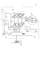
- FIG. 1 is a configuration diagram of a power converter
- FIG. 2 is a flowchart showing the temperature rise control process
- FIG. 3 is a diagram showing an equivalent circuit
- FIG. 4 is a functional block diagram of the control device
- FIG. 5 is a diagram showing a method of setting the command current
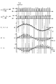
- FIG. 6 is a time chart showing the transition of the switch control mode
- FIG. 7 is a diagram showing simulation results
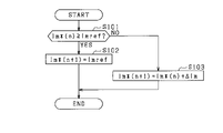
- FIG. 8 is a flowchart of command current setting processing
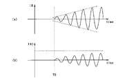
- FIG. 9 is a time chart showing changes in current and torque flowing through the neutral point
- FIG. 10 is a flowchart of command current setting processing in the second embodiment
- FIG. 10 is a flowchart of command current setting processing in the second embodiment
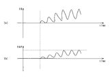
- FIG. 11 is a time chart showing changes in current and torque flowing through the neutral point in the second embodiment
- FIG. 12 is a flowchart of command current setting processing in the third embodiment
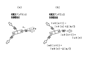
- FIG. 13 is a diagram for explaining phase current imbalance control
- FIG. 14 is a diagram schematically showing the windings and magnetic poles of each phase
- FIG. 15 is a diagram schematically showing the windings and magnetic poles of each phase
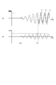
- FIG. 16 is a time chart showing changes in phase current and torque in the third embodiment
- FIG. 17 is a flowchart of command current setting processing in the fourth embodiment
- FIG. 18 is a time chart showing changes in current and torque flowing through the neutral point in the fourth embodiment
- FIG. 19 is a flowchart of command current setting processing in the fifth embodiment
- FIG. 20 is a time chart showing changes in current and torque flowing through the neutral point in the fifth embodiment
- FIG. 21 is a time chart showing changes in current and torque flowing through the neutral point in the modified example
- FIG. 22 is a time chart showing changes in current and torque flowing through the neutral point in the modified example.
- the power conversion device 10 includes an inverter 30 as a power converter connected to a rotating electric machine 40 .
- the power converter 10 has a function of exchanging electric power between the assembled battery 20 and the rotating electric machine 40 via the inverter 30 in order to raise the temperature of the assembled battery 20 as a battery.
- the rotary electric machine 40 is a three-phase synchronous machine, and includes star-connected U-, V-, and W-phase windings 41U, 41V, and 41W as stator windings.
- the phase windings 41U, 41V, and 41W are arranged with an electrical angle shift of 120°.
- the rotating electric machine 40 is, for example, a permanent magnet synchronous machine.
- the rotary electric machine 40 is a vehicle-mounted main machine and serves as a driving power source for the vehicle. That is, the rotating electric machine 40 is connected to the axle.
- the inverter 30 has three phases of series connections of upper arm switches QUH, QVH, QWH and lower arm switches QUL, QVL, QWL.
- voltage-controlled semiconductor switching elements are used as the switches QUH, QVH, QWH, QUL, QVL, and QWL, and more specifically, IGBTs and MOSFETs are used.
- Diodes DUH, DVH, DWH, DUL, DVL, and DWL as freewheel diodes are connected in antiparallel to the switches QUH, QVH, QWH, QUL, QVL, and QWL.
- a U-phase winding 41U of rotating electrical machine 40 is connected to a low-potential terminal of U-phase upper arm switch QUH and a high-potential terminal of U-phase lower arm switch QUL via U-phase conductive member 32U such as a bus bar. A first end is connected.
- the V-phase winding 41V of the rotary electric machine 40 is connected to the low-potential side terminal of the V-phase upper arm switch QVH and the high-potential side terminal of the V-phase lower arm switch QVL via a V-phase conductive member 32V such as a bus bar. A first end is connected.
- the W-phase winding 41W of the rotary electric machine 40 is connected to the low-potential side terminal of the W-phase upper arm switch QWH and the high-potential side terminal of the W-phase lower arm switch QWL via a W-phase conductive member 32W such as a bus bar.
- a first end is connected.
- Second ends of the U-, V-, and W-phase windings 41U, 41V, and 41W are connected at a neutral point O.
- each phase winding 41U, 41V, 41W is set to have the same number of turns.
- the phase windings 41U, 41V, and 41W are set to have the same inductance, for example.
- the high-potential side terminals of the upper arm switches QUH, QVH, and QWH and the positive terminal of the assembled battery 20 are connected by a positive-side bus line Lp such as a bus bar.
- the low potential side terminals of the lower arm switches QUL, QVL, QWL and the negative terminal of the assembled battery 20 are connected by a negative bus line Ln such as a bus bar.
- the power conversion device 10 includes a capacitor (smoothing capacitor) 31 that connects the positive electrode side bus Lp and the negative electrode side bus Ln.
- the capacitor 31 may be built in the inverter 30 or may be provided outside the inverter 30 .
- the assembled battery 20 is configured as a series connection of battery cells as single cells, and has a terminal voltage of, for example, several hundred volts.
- the terminal voltages (for example, rated voltages) of the battery cells forming the assembled battery 20 are set to be the same.
- a battery cell for example, a secondary battery such as a lithium ion battery can be used.
- the assembled battery 20 is divided into two blocks.
- the number of battery cells constituting the first storage battery 21 and the number of battery cells constituting the second storage battery 22 are the same. Therefore, the terminal voltage (eg, rated voltage) of the first storage battery 21 and the terminal voltage (eg, rated voltage) of the second storage battery 22 are the same.
- an intermediate terminal B is connected to the negative terminal of the first storage battery 21 and the positive terminal of the second storage battery 22 .
- the power conversion device 10 includes a monitoring unit 50 (corresponding to a voltage information detection section).
- the monitoring unit 50 monitors the terminal voltage, SOC, SOH, temperature, etc. of each battery cell that constitutes the assembled battery 20 .
- the power electronics device 10 includes a connection path 60 and a connection switch 61 .
- Connection path 60 electrically connects intermediate terminal B and neutral point O of assembled battery 20 .
- the connection switch 61 is provided on the connection path 60 .
- a relay is used as the connection switch 61 .
- the intermediate terminal B and the neutral point O are electrically connected by turning on the connection switch 61 .
- the intermediate terminal B and the neutral point O are electrically cut off by turning off the connection switch 61 .
- the power conversion device 10 includes a current sensor 62 that detects the current flowing through the connection path 60 (that is, the current flowing through the neutral point). A value detected by the current sensor 62 is input to a control device 70 (corresponding to a control unit) included in the power conversion device 10 .
- the control device 70 is mainly composed of a microcomputer, and performs switching control of each switch that constitutes the inverter 30 in order to feedback-control the control amount of the rotating electrical machine 40 to its command value.
- the power conversion device 10 converts the DC power of the assembled battery 20 into AC power and supplies it to the rotating electric machine 40 .
- the controlled variable is, for example, torque.
- the control device 70 controls on/off of the connection switch 61 and is capable of communicating with the monitoring unit 50 . Further, the control device 70 can communicate with a host control device 80 provided outside the power conversion device 10 . The host controller 80 supervises the control of the vehicle.
- control device 70 implements various control functions by executing programs stored in its own storage device.
- Various functions may be implemented by an electronic circuit that is hardware, or may be implemented by both hardware and software.
- FIG. 2 is a flow chart showing the procedure of temperature increase control processing. This process is repeatedly executed by the control device 70, for example, at a predetermined control cycle.
- step S10 it is determined whether or not there is a request to raise the temperature of the assembled battery 20. For example, when it is determined that there is an instruction to raise the temperature of the assembled battery 20 from the host controller 80, or when it is determined that the temperature of the assembled battery 20 detected by the monitoring unit 50 is less than the threshold temperature, there is a request to raise the temperature. should be determined.
- the temperature to be compared with the threshold temperature may be, for example, the lowest temperature among the detected temperatures of the battery cells, or the average temperature of the battery cells calculated based on the detected temperatures of the battery cells. .
- the situation in which the positive determination is made in step S10 assumes that the vehicle is stopped before the rotating electric machine 40 is driven.
- step S10 If it is determined in step S10 that there is no request to raise the temperature, the process advances to step S11 to determine whether or not there is a request to drive the rotating electric machine 40 .
- the drive request includes a request to drive the vehicle by rotationally driving the rotating electric machine 40 .
- step S11 If it is determined in step S11 that there is no drive request, the process proceeds to step S12 to set the standby mode. By setting this mode, the switches QUH to QWL of the inverter 30 are turned off. Then, in step S13, the connection switch 61 is turned off. Thereby, the intermediate terminal B and the neutral point O are electrically cut off.
- step S11 If it is determined in step S11 that there is a drive request, the process proceeds to step S14 to set the drive mode of the rotating electric machine 40. Then, in step S16, the connection switch 61 is turned on. Thereby, intermediate terminal B and neutral point O are electrically connected via connection path 60 . After that, in step S16, switching control of each of the switches QUH to QWL of the inverter 30 is performed in order to rotationally drive the rotary electric machine 40. FIG. As a result, the drive wheels of the vehicle rotate and the vehicle can run.
- step S16 may be performed using, for example, PWM based on a magnitude comparison between the command voltage applied to each phase winding 41U to 41W and the carrier signal (eg, triangular wave signal), or by using a pulse pattern. .
- step S10 If it is determined in step S10 that there is a temperature increase request, the process proceeds to step S17 to set the temperature increase control mode.
- step S18 the connection switch 61 is turned on.
- step S19 temperature-increasing PWM control for increasing the temperature of the assembled battery 20 is performed. This control will be described below.
- FIG. 3(a) shows an equivalent circuit of the power conversion device 10 used in temperature-rising PWM control.
- each phase winding 41U to 41W is shown as winding 41
- upper arm switches QUH, QVH, QWH are shown as upper arm switch QH
- upper arm diodes DUH, DVH, DWH are shown as upper arm switches. Shown as diode DH.
- the lower arm switches QUL, QVL, QWL are shown as a lower arm switch QL
- the lower arm diodes DUL, DVL, DWL are shown as a lower arm diode DL.
- the equivalent circuit of FIG. 3(a) can be shown as the equivalent circuit of FIG. 3(b).
- the circuit of FIG. 3B is a step-up/step-down chopper circuit capable of bi-directional power transmission between the first storage battery 21 and the second storage battery 22 .
- VBH indicates the terminal voltage of the first storage battery
- IBH indicates the current flowing through the first storage battery
- VBL indicates the terminal voltage of the second storage battery 22
- IBL indicates the voltage across the second storage battery 22.
- Indicates current flow. IBH and IBL are negative when charging currents of the first and second storage batteries 21 and 22 flow, and IBH and IBL are positive when discharging currents of the first and second storage batteries 21 and 22 flow.
- VR indicates the terminal voltage of the winding 41
- IR indicates the current flowing through the neutral point O (corresponding to the current value of the rotating electric machine). IR is negative when current flows to neutral point O in the positive direction from winding 41 to intermediate terminal B, and IR is positive when current flows to neutral point O in the opposite direction.
- Fig. 4 shows a block diagram of the temperature rising PWM control.
- current deviation calculation unit 71 calculates a current deviation by subtracting the current detected by current sensor 62 (hereinafter, detected current IMr) from command current Im*.
- the command current Im* is set as a sine wave, as shown in FIG. Specifically, in one cycle Tc of the command current Im*, the command current Im* is adjusted so that the positive command current Im* and the negative command current Im* are point symmetrical with respect to the zero cross timing of the command current Im*. set. As a result, the period from the zero up-cross timing to the zero down-cross timing of the command current Im* becomes the same as the period from the zero down-cross timing to the zero up-cross timing of the command current Im*.
- the area S1 of the first region and the area S2 of the second region become equal.
- the first region S1 is a region surrounded by the positive command current Im* and the time axis from the zero-up cross timing to the zero-down cross timing of the command current Im* in one cycle Tc of the command current Im*.
- the second region is a region surrounded by the negative command current Im* and the time axis from the zero down-crossing timing to the zero up-crossing timing of the command current Im* in one cycle Tc.
- the frequency fc of the command current Im* which is the reciprocal of one cycle Tc of the command current Im*, is preferably set to a frequency on the lower limit side of the human audible range, for example.
- the frequency fc is desirably set to 1 kHz or less, which is a frequency range in which the correction value (dB) is 0 or less in the A characteristic, and more desirably, a frequency between 30 Hz and 100 Hz (for example, 50 Hz ).
- the feedback control unit 72 calculates a duty ratio Duty as an operation amount for feedback-controlling the calculated current deviation to zero.
- the duty ratio Duty is a value that determines the ratio (Ton/Tsw) of the ON time Ton in one switching cycle Tsw of each of the switches QUH to QWL.
- the feedback control used in the feedback control section 72 may be proportional integral control, for example.
- the PWM generator 73 generates gate signals for the upper arm switches QUH, QVH, and QWH based on the calculated duty ratio Duty.
- a gate signal is a signal that instructs ON control or OFF control.
- the gate signals of the upper arm switches QUH, QVH, QWH are synchronized.
- the inverter 74 generates gate signals for the lower arm switches QUL, QVL, QWL by inverting the logic of the gate signals for the upper arm switches QUH, QVH, QWH generated by the PWM generator 73 .
- the gate signals of the lower arm switches QUL, QVL, QWL are synchronized.
- FIG. 6 shows the transition of the switching pattern, etc. during temperature-rising PWM control.
- FIG. 6(a) shows transitions of the gate signals of the upper arm switches QUH, QVH, QWH, and
- FIG. 6(b) shows transitions of the gate signals of the lower arm switches QUL, QVL, QWL.
- FIG. 6(c) shows changes in the current IR flowing through the neutral point O and changes in the command current Im*.
- FIG. 6(d) shows changes in the current IBH flowing through the first storage battery 21, and
- FIG. 6(e) shows changes in the current IBL flowing through the second storage battery 22. As shown in FIG.
- temperature-rising PWM control is performed in which the upper arm switches QUH, QVH, QWH and the lower arm switches QUL, QVL, QWL are alternately controlled to be ON. This control is continued until the temperature increase request in step S10 in FIG. 2 is no longer issued.
- a pulsed current flows through the first storage battery 21 and the second storage battery 22.
- the average values IBHave and IBLave of the pulse-like currents are sinusoidal currents containing the same frequency component as the frequency of the command current Im*.
- FIG. 7 shows the simulation results of this embodiment.
- FIGS. 7(a) to (c) correspond to FIGS. 6(c) to (e).
- a sinusoidal current flows through the first storage battery 21 and the second storage battery 22, and the temperature can be raised.
- the terminal voltage of the capacitor 31 does not fluctuate.
- the rotor may be rotationally driven.
- the temperature increase control is performed while the vehicle is stopped. Therefore, when a large current is suddenly applied to the rotating electrical machine 40, the rotor is rotationally driven, and the rotating electrical machine 40 unintentionally causes the temperature to exceed a predetermined value. is output, and there is a risk that the vehicle will move beyond the holding torque of the parking brake.
- the command current Im* is set as follows, and the magnitude of the current IR flowing through the neutral point O is controlled.
- control device 70 executes a command current setting process for determining command current Im* shown in FIG.
- the command current setting process is executed at predetermined intervals during temperature rise control.
- the control device 70 determines whether or not the command current Im*(n) ⁇ the target value Imref (step S101).
- the command current Im*(n) is the command current Im* in the current process, and "n" indicates the number of times the command current setting process is executed.
- the command current Im*(0) which is the initial value of the command current Im*(n)
- the target value Imref is a desired amplitude command value of the current IR for raising the temperature of the first storage battery 21 and the second storage battery 22, and is set within a current control range in which the torque of the rotary electric machine 40 is less than the upper limit torque.
- the target value Imref corresponds to the upper limit of the current control range.
- the upper limit torque is a torque that is set based on the parking brake holding torque that can keep the vehicle in a stopped state, and is set to a value that is equal to or lower than the parking brake holding torque.
- step S101 determines whether the determination result in step S101 is affirmative. If the determination result in step S101 is affirmative, the control device 70 sets the target value Imref as the command current Im*(n+1) in the next process (step S102). After the process of step S102, the control device 70 ends the command current setting process.
- the control device 70 sets a value obtained by adding the amplitude increase amount ⁇ Im to the current command current Im*(n) as the command current Im*(n+1) in the next process.
- the amplitude increase amount ⁇ Im is the amplitude increase amount per unit time (time change rate, increase rate), and is set to a value that is at least less than the upper limit torque.
- the amplitude increase amount ⁇ Im is set so that the command current Im* reaches the target value Imref in a plurality of times (for example, about 5 to 10 times) so that the rate of temperature rise does not become too slow. is desirable.
- the control device 70 ends the command current setting process.
- the current IR (amplitude of) flowing through the neutral point O gradually increases within the current control range determined by the upper limit torque from the temperature rise control start time T0. becomes.
- the torque of the rotary electric machine 40 also gradually increases as shown in FIG. 9B, but it is possible to prevent it from exceeding the upper limit torque (indicated by the dashed line). That is, it is possible not to exceed the parking brake holding torque.
- the control device controls the current so that the current IR is gradually increased within the current control range in which the torque of the rotating electric machine 40 is less than the upper limit torque.
- the intermediate terminal B (corresponding to the intermediate point) and the neutral point O are connected by a connection path 60 without passing through the switches QUH to QWL of the inverter 30 .
- the control device 70 controls the inverter 30 so that a ripple current flows between the first storage battery 21 and the second storage battery 22 via the inverter 30, the phase windings 41U, 41V, 41W, and the connection path 60. switching control.
- the amount of fluctuation in the terminal voltage of the capacitor 31 can be reduced, the capacity of the capacitor 31 can be reduced, and the size of the capacitor 31 can be reduced.
- the control device 70 synchronizes the switching control of the upper arm switches QUH, QVH, QWH of all phases and also synchronizes the switching control of the lower arm switches QUL, QVL, QWL of all phases in the temperature rise control.
- each phase winding 41U, 41V, 41W can be regarded as an equivalent circuit in which windings are connected in parallel. Therefore, it is possible to reduce the inductance of the windings during the temperature rise control. As a result, the amount of change in the current flowing through the neutral point O can be increased in one switching cycle Tsw, and temperature rise control can be performed using a large current.
- the control device 70 turns on the connection switch 61 when it determines that there is a request to raise the temperature of the assembled battery 20, and turns off the connection switch 61 when it determines that there is no request to raise the temperature. As a result, it is possible to suppress current from flowing from the neutral point O to the intermediate terminal B when the vehicle is running.
- control device 70 determines whether or not command current Im*(n) ⁇ target value Imref (step S201), similar to step S101. If the determination result is affirmative, control device 70 sets target value Imref as command current Im*(n+1) in the next process, as in step S102 (step S202). Then, the control device 70 ends the command current setting process.
- step S201 determines whether or not the rotor is moving.
- control device 70 adds the current command current Im*(n) and the amplitude increase amount ⁇ Im to the next process, as in step S103. (step S204). Then, the control device 70 ends the command current setting process.
- step S203 determines whether the current command current Im*(n) is negative, that is, if the rotor has moved.
- the controller 70 subtracts the amplitude margin ⁇ Imm from the current command current Im*(n), and converts it to the command current Im in the next process.
- *(n+1) is set (step S205).
- the amplitude margin ⁇ Imm is a predetermined positive value, and is preset to a value that allows the rotor to remain stationary.
- An arbitrary value may be set as the amplitude margin ⁇ Imm, but it is desirable that it be about half the amplitude increase ⁇ Im to a value equivalent to the amplitude increase ⁇ Im.
- a value smaller than the current command current Im*(n) by the amplitude margin ⁇ Imm is set as the command current Im*(n+1) for the next and subsequent processes.
- the control device 70 determines that the upper limit torque has been reached, and sets a value smaller than the current command current Im*(n) by an amplitude margin ⁇ Imm so that the rotor does not move any further. Set as current Im*(n+1). As a result, the operation of the vehicle can be suppressed, and the command current Im* can be increased to the limit of the upper torque limit. This makes it possible to raise the temperature quickly.
- the control device 70 sets a value smaller by the amplitude margin ⁇ Imm as the command current Im*(n+1) for subsequent processing.
- the amount of increase in amplitude ⁇ Im can be set to a value as large as possible, and forward movement of the vehicle can be suppressed while realizing early temperature rise.
- control device 70 is configured to be able to control the phase currents of the windings 41 of each phase of the rotary electric machine 40 . That is, the power conversion device 10 detects the phase current of the winding 41 of each phase of the rotating electrical machine 40 (corresponding to the current value of the rotating electrical machine in the third embodiment), and compares the detected value and the command value of each phase current. By comparison, the phase current of the winding 41 of each phase of the rotary electric machine 40 is controlled.
- control device 70 When the control device 70 starts the command current setting process shown in FIG. 12, the command currents Iu*(n), Iv*(n), Iw*(n) that command the amplitude of the phase currents of the windings 41 of the respective phases. is obtained (step S301).
- the command current Iu*(n) commands the amplitude of the U-phase current in the current process.
- the command current Iv*(n) commands the amplitude of the V-phase current in the current process.
- the command current Iw*(n) commands the amplitude of the W-phase current in the current process.
- control device 70 determines whether or not command current Iu*(n)+Iv*(n)+Iw*(n) ⁇ target value Imref (step S301). That is, it is determined whether or not the sum of the command currents Iu*(n), Iv*(n), and Iw*(n) is greater than or equal to the target value Imref.
- control device 70 terminates the command current setting process shown in FIG.
- the current command currents Iu*(n), Iv*(n) and Iw*(n) are used as the next command currents Iu*(n+1), Iv*(n+1) and Iw*(n+1).
- step S301 determines whether or not the rotor is moving.
- step S302 If the determination result in step S302 is affirmative, that is, if the rotor is not moving, the controller 70 controls the current command currents Iu*(n), Iv*(n), Iw*(n) to The values obtained by adding the amplitude increments ⁇ Im/3 are set as the command currents Iu*(n+1), Iv*(n+1), and Iw*(n+1) in the next processing (step S303).
- the amplitude increase amount ⁇ Im/3 is 1 ⁇ 3 of the amplitude increase amount ⁇ Im described in the first embodiment.
- step S303 determines whether the command currents Iu*(n+1) and Iv*(n+1) in the next process. ) and Iw*(n+1) (step S304).
- the control device 70 controls the command currents Iu*(n+1), Iv*(n+1), Iw * Determine (n+1).
- the direction of the phase current refers to the case where the phase current flows from the side of the inverter 30 to the side of the neutral point O as shown in FIG. It is divided into cases where it flows to the side.
- the rotor position ⁇ e is the position of the rotor magnetic pole 90 (for example, the N pole) expressed in electrical angle with the position of the U-phase winding 41U set to 0° (reference). be. This is an example, and the reference may be the position of any winding 41 or the S pole.
- the current The command current Iu*(n) is set as the next command current Iu*(n+1).
- the amplitude increase amount ⁇ Im/3 is added to the current command current Iv*(n). The added value is set as the next command current Iv*(n+1).
- the amplitude increase amount ⁇ Im/3 is added to the current command current Iw*(n).
- the subtracted value is set as the next command current Iw*(n+1).
- the magnitude of the amplitude of the phase current becomes unbalanced and the torque of the rotary electric machine 40 decreases in the subsequent processing.
- the rotor position ⁇ e is 20° (0° ⁇ e ⁇ 30°), and the phase current flows from the neutral point O side to the inverter 30 side (neutral point ⁇ inverter). It shows how the phase currents are unbalanced when they are flowing.
- the (amplitude of) each phase current gradually increases from the control start time T10 as shown in FIG. 16(a).
- the torque of the rotary electric machine 40 also gradually increases from time T10, as shown in FIG. 16(b).
- the phase currents Iu, Iv, and Iw are controlled to be unbalanced, and this state is maintained.
- the torque of the rotary electric machine 40 is reduced from time T11 when it reaches the upper limit torque, and the state is maintained.
- the solid line indicates the phase current Iu
- the one-dot chain line indicates the phase current Iv
- the two-dot chain line indicates the phase current Iw.
- the control device 70 determines that the rotor has exceeded the upper limit torque, and controls the magnitude of the amplitude of the phase current in the winding 41 of each phase to be unbalanced so that the rotor does not move any further. . Specifically, the control device 70 acquires the rotor position ⁇ e, and adjusts the phase currents of the windings 41 based on the direction of the phase currents of the windings 41 and the rotor position ⁇ e so that the phase currents of the windings 41 become unbalanced. Then, the command currents Iu*(n+1), Iv*(n+1), Iw*(n+1) are determined.
- the amplitude increment ⁇ Im/3 is added to the winding 41 whose amplitude is to be increased, and the amplitude increment ⁇ Im/3 is subtracted to the winding 41 whose amplitude is to be decreased.
- the amplitude increase amount ⁇ Im/3 to be added or subtracted has the same value, the total value of the command currents Iu*(n), Iv*(n) and Iw*(n) can be maintained. In other words, the torque can be reduced without reducing the total value. Therefore, the temperature can be raised more quickly.
- the control device 70 acquires vehicle attitude information and determines the upper limit torque based on the vehicle attitude information (step S400).
- the vehicle posture information is information for grasping on what slope the vehicle is stopped on the road, based on the inclination of the vehicle. For example, when the vehicle is stopped on a downward slope, the parking brake holding torque becomes smaller due to the weight of the vehicle compared to when the vehicle is stopped on a flat ground or an upward slope. In other words, even if the torque of the rotary electric machine 40 is small, it becomes easier to move forward. Therefore, in step S400, the upper limit torque is determined based on the vehicle posture information in consideration of this.
- the upper limit torque is set to be the same as that for flat terrain even for an uphill slope, but the upper limit torque may be increased for an uphill slope.
- the control device 70 determines whether or not the command current Im*(n) ⁇ the target value Imref (step S401).
- the current limit range may be changed according to the upper limit torque, and the target value Imref may be changed accordingly. That is, as the upper limit torque becomes smaller, the target value Imref may be reduced so that the torque of the rotary electric machine 40 does not exceed the upper limit torque.
- step S401 If the determination result in step S401 is affirmative, the control device 70 sets the target value Imref as the command current Im*(n+1) in the next process, similarly to step S102 (step S402).
- the controller 70 sets a value obtained by adding the amplitude increase amount ⁇ Im to the current command current Im*(n) as the command current Im*(n+1) in the next process.
- the amplitude increase amount ⁇ Im is set to a value that is at least less than the upper limit torque.
- the amplitude increase amount ⁇ Im is set so that the command current Im* reaches the target value Imref in a plurality of times (for example, about 5 to 10 times) so that the rate of temperature rise does not become too slow. is desirable. Therefore, the amplitude increase amount ⁇ Im may be changed according to the target value Imref.
- the current IR (amplitude of) flowing through the neutral point O as shown in FIG. 18(a) gradually increases within the current control range.
- the torque of the rotary electric machine 40 also gradually increases as shown in FIG. Note that when the slope is 0% (the upper limit torque is indicated by the broken line) and the downward slope is large (for example, 10%), the upper limit torque becomes smaller (indicated by the dashed line).
- the control device 70 acquires vehicle attitude information when the vehicle is stopped, and changes the upper limit torque based on the vehicle attitude information. Along with this, the control device 70 sets the target value Imref within a current limit range that does not exceed the upper torque limit. Accordingly, control device 70 controls the current so as to gradually increase current IR within a current control range in which the torque of rotating electrical machine 40 is less than the upper limit torque. Therefore, when the vehicle is stopped on a downward slope, it is possible to prevent the vehicle from moving based on the temperature increase control.
- the control device 70 determines the amplitude increase amount ⁇ Im1 and the amplitude decrease amount ⁇ Im2 (step S500). Specifically, the control device 70 controls the amplitude increase amount according to the state of the assembled battery 20 (battery temperature, SOC), the upper limit torque, the current control range, the target value Imref, or any combination thereof. ⁇ Im1 should be determined.
- the amplitude increase amount ⁇ Im1 is the amplitude increase amount per unit time (time change rate, increase rate), like the amplitude increase amount ⁇ Im in the first embodiment.
- the amplitude reduction amount ⁇ Im2 is the amplitude reduction amount per unit time (time change rate, reduction rate).
- the amplitude decrease amount ⁇ Im2 may be set to a value smaller than the amplitude increase amount ⁇ Im1.
- control device 70 determines whether or not the command current Im*(n) ⁇ the target value Imref (step S501).
- step S502 determines whether the command current setting process is a command current setting process. If the determination result in step S502 is negative, the control device 70 subtracts the amplitude decrease amount ⁇ Im2 determined in step S500 from the current command current Im*(n), *(n+1) is set (step S504). Then, the control device 70 ends the command current setting process.
- control device 70 adds the amplitude increase amount ⁇ Im1 determined in step S500 to the current command current Im*(n), and adds the value to command current Im in the next process. *(n+1) is set (step S505). Then, the control device 70 ends the command current setting process.
- the rate of increase (indicated by the dashed line) of (the amplitude of) the current IR flowing through the neutral point O can be arbitrarily changed as shown in FIG. 20(a).
- the rate of decrease of (the amplitude of) the current IR can be arbitrarily changed.
- An appropriate amplitude increase amount ⁇ Im1 can be set based on the state of the assembled battery 20 (battery temperature, SOC), upper limit torque, current control range, target value Imref, and other values. As a result, the current can be raised quickly. Moreover, since the appropriate amplitude increase amount ⁇ Im1 is set, it is possible to prevent the upper limit torque of the rotating electric machine 40 from being exceeded. In addition, since the amplitude reduction amount ⁇ Im2 can be set, when the target value Imref is exceeded, the command current Im*(n+1) in subsequent processing can be quickly reduced to the target value Imref or less.
- a current obtained by combining a direct current and an alternating current may be supplied to the assembled battery 20 to perform the temperature increase control.
- the assembled battery 20 is used, but a single battery may be used.
- temperature rising PWM control may be performed by on/off controlling two phases out of the three phases.
- control device 70 may cause current to flow between the capacitor 31 and the assembled battery 20 via the inverter 30 and the winding 41 .
- the imbalance is achieved by adding and subtracting the same amplitude increase amount ⁇ Im/3, but the amplitude increase amount to be added and the amplitude increase amount to be subtracted are set to different values. may It should be unbalanced as a result.
Landscapes
- Engineering & Computer Science (AREA)
- Power Engineering (AREA)
- Life Sciences & Earth Sciences (AREA)
- Sustainable Development (AREA)
- Sustainable Energy (AREA)
- Transportation (AREA)
- Mechanical Engineering (AREA)
- Electric Propulsion And Braking For Vehicles (AREA)
- Control Of Ac Motors In General (AREA)
- Inverter Devices (AREA)
Abstract
Description
以下、本開示に係る電力変換装置を具体化した第1実施形態について、図面を参照しつつ説明する。本実施形態において、電力変換装置は車両に搭載されている。なお、以下の各実施形態相互において、互いに同一又は均等である部分には、図中、同一符号を付しており、同一符号の部分についてはその説明を援用する。
第2実施形態における指令電流設定処理について図10に基づいて説明する。第2実施形態では、第1実施形態における基本構成を採用し、第1実施形態と異なる構成を中心に説明する。
第3実施形態における指令電流設定処理について図12に基づいて説明する。第3実施形態では、第1実施形態における基本構成を採用し、第1実施形態と異なる構成を中心に説明する。
第4実施形態における指令電流設定処理について図17に基づいて説明する。第4実施形態では、第1実施形態における基本構成を採用し、第1実施形態と異なる構成を中心に説明する。
第5実施形態における指令電流設定処理について図19に基づいて説明する。第5実施形態では、第1実施形態における基本構成を採用し、第1実施形態と異なる構成を中心に説明する。
上記実施形態における構成の一部を、以下に説明するように変更してもよい。以下、変形例について説明する。
Claims (9)
- 上アームスイッチ(QUH,QVH,QWH)及び下アームスイッチ(QUL,QVL,QWL)の直列接続体を有し、スイッチング制御によりバッテリ(20)から供給される直流電力を交流電力に変換する電力変換器(30)を備え、前記電力変換器からの交流電力を、車両の車軸に連結され、巻線(41)を有する回転電機(40)に供給する電力変換装置(10)において、
前記電力変換器及び前記巻線を介して前記バッテリに電流が流れるように、前記上アームスイッチ及び前記下アームスイッチのスイッチング制御を行って、前記バッテリの昇温制御を行う制御部(70)を備え、
前記制御部は、車両停止時の昇温制御において、前記回転電機のトルクが上限トルク未満となる電流制御範囲内で、前記回転電機の電流値を徐々に増加させるように、電流を制御する電力変換装置。 - 前記バッテリは、中間点において直列接続された第1蓄電池(21)及び第2蓄電池(22)から構成されており、
前記中間点と、前記巻線の中性点とを電気的に接続する接続経路(60)を備え、
前記制御部は、前記電力変換器、前記巻線及び前記接続経路を介して前記第1蓄電池と前記第2蓄電池との間に電流が流れるように、前記上アームスイッチ及び前記下アームスイッチのスイッチング制御を行う請求項1に記載の電力変換装置。 - 前記制御部は、前記電流値を徐々に増加させた結果、前記電流制御範囲の上限値に達した場合、当該上限値又は上限値を下回る値となるように、前記電流値を制御する請求項1又は2に記載の電力変換装置。
- 前記制御部は、前記回転電機のロータの位置を取得し、前記電流値を徐々に増加させる際、前記ロータの位置が動いたとき、動作時における電流値以下となるように、前記電流値を制御する請求項1~3のうちいずれか1項に記載の電力変換装置。
- 前記制御部は、車両の姿勢に関する車両姿勢情報を取得し、車両姿勢情報に応じて前記上限トルクを変更する請求項1~4のうちいずれか1項に記載の電力変換装置。
- 前記制御部は、前記巻線に流れる電流を交流電流とする請求項1~5のうちいずれか1項に記載の電力変換装置。
- 前記制御部は、前記回転電機の電流値の単位時間当たりの増加率又は減少率を変更可能に構成されている請求項1~6のうちいずれか1項に記載の電力変換装置。
- 前記回転電機は、複数相の巻線(41U,41V,41W)を有し、
前記制御部は、前記回転電機のロータの位置を取得し、前記ロータの位置が動いた場合、前記各巻線の相電流の向きと前記ロータの位置に基づいて、前記各巻線の相電流がアンバランスとなるように制御する請求項1~7のうちいずれか1項に記載の電力変換装置。 - 前記制御部は、前記各巻線の相電流をアンバランスとなるように制御する際、複数相の相電流のうち少なくとも1つの相電流の振幅を大きくする一方、複数相の相電流のうち少なくとも1つの相電流の振幅を小さくする請求項8に記載の電力変換装置。
Priority Applications (4)
| Application Number | Priority Date | Filing Date | Title |
|---|---|---|---|
| EP22784424.8A EP4322395B1 (en) | 2021-04-09 | 2022-03-11 | Power conversion device |
| CN202280026093.8A CN117157871A (zh) | 2021-04-09 | 2022-03-11 | 电力转换装置 |
| US18/377,545 US12413169B2 (en) | 2021-04-09 | 2023-10-06 | Power conversion apparatus |
| US19/291,056 US20250357880A1 (en) | 2021-04-09 | 2025-08-05 | Power conversion apparatus |
Applications Claiming Priority (2)
| Application Number | Priority Date | Filing Date | Title |
|---|---|---|---|
| JP2021-066577 | 2021-04-09 | ||
| JP2021066577A JP7600837B2 (ja) | 2021-04-09 | 2021-04-09 | 電力変換装置 |
Related Child Applications (1)
| Application Number | Title | Priority Date | Filing Date |
|---|---|---|---|
| US18/377,545 Continuation US12413169B2 (en) | 2021-04-09 | 2023-10-06 | Power conversion apparatus |
Publications (1)
| Publication Number | Publication Date |
|---|---|
| WO2022215439A1 true WO2022215439A1 (ja) | 2022-10-13 |
Family
ID=83546315
Family Applications (1)
| Application Number | Title | Priority Date | Filing Date |
|---|---|---|---|
| PCT/JP2022/011099 Ceased WO2022215439A1 (ja) | 2021-04-09 | 2022-03-11 | 電力変換装置 |
Country Status (5)
| Country | Link |
|---|---|
| US (2) | US12413169B2 (ja) |
| EP (1) | EP4322395B1 (ja) |
| JP (1) | JP7600837B2 (ja) |
| CN (1) | CN117157871A (ja) |
| WO (1) | WO2022215439A1 (ja) |
Families Citing this family (3)
| Publication number | Priority date | Publication date | Assignee | Title |
|---|---|---|---|---|
| JP7782485B2 (ja) * | 2023-02-06 | 2025-12-09 | トヨタ自動車株式会社 | 車両電源装置 |
| US20250239944A1 (en) * | 2024-01-22 | 2025-07-24 | Ford Global Technologies, Llc | Power module gate oxide self-healing method |
| WO2026058361A1 (ja) * | 2024-09-11 | 2026-03-19 | Astemo株式会社 | モータ制御装置 |
Citations (4)
| Publication number | Priority date | Publication date | Assignee | Title |
|---|---|---|---|---|
| US6882061B1 (en) * | 1998-12-31 | 2005-04-19 | Daimlerchrysler Corporation | Battery self-warming mechanism using the inverter and the battery main disconnect circuitry |
| JP2007028702A (ja) * | 2005-07-12 | 2007-02-01 | Toyota Motor Corp | 二次電池の制御装置 |
| JP2020120566A (ja) * | 2019-01-24 | 2020-08-06 | 株式会社Soken | 電力変換装置 |
| JP2021066577A (ja) | 2019-10-25 | 2021-04-30 | 上海交通大学Shanghai Jiao Tong University | エレベータ |
Family Cites Families (2)
| Publication number | Priority date | Publication date | Assignee | Title |
|---|---|---|---|---|
| JP4957538B2 (ja) * | 2007-12-27 | 2012-06-20 | アイシン・エィ・ダブリュ株式会社 | コンバータ装置,回転電機制御装置および駆動装置 |
| CN108306078A (zh) * | 2018-03-07 | 2018-07-20 | 苏州汇川联合动力系统有限公司 | 动力电池加热系统及方法 |
-
2021
- 2021-04-09 JP JP2021066577A patent/JP7600837B2/ja active Active
-
2022
- 2022-03-11 WO PCT/JP2022/011099 patent/WO2022215439A1/ja not_active Ceased
- 2022-03-11 CN CN202280026093.8A patent/CN117157871A/zh active Pending
- 2022-03-11 EP EP22784424.8A patent/EP4322395B1/en active Active
-
2023
- 2023-10-06 US US18/377,545 patent/US12413169B2/en active Active
-
2025
- 2025-08-05 US US19/291,056 patent/US20250357880A1/en active Pending
Patent Citations (4)
| Publication number | Priority date | Publication date | Assignee | Title |
|---|---|---|---|---|
| US6882061B1 (en) * | 1998-12-31 | 2005-04-19 | Daimlerchrysler Corporation | Battery self-warming mechanism using the inverter and the battery main disconnect circuitry |
| JP2007028702A (ja) * | 2005-07-12 | 2007-02-01 | Toyota Motor Corp | 二次電池の制御装置 |
| JP2020120566A (ja) * | 2019-01-24 | 2020-08-06 | 株式会社Soken | 電力変換装置 |
| JP2021066577A (ja) | 2019-10-25 | 2021-04-30 | 上海交通大学Shanghai Jiao Tong University | エレベータ |
Non-Patent Citations (1)
| Title |
|---|
| See also references of EP4322395A4 |
Also Published As
| Publication number | Publication date |
|---|---|
| EP4322395B1 (en) | 2026-02-18 |
| JP7600837B2 (ja) | 2024-12-17 |
| US20250357880A1 (en) | 2025-11-20 |
| EP4322395A4 (en) | 2024-11-13 |
| EP4322395A1 (en) | 2024-02-14 |
| CN117157871A (zh) | 2023-12-01 |
| US12413169B2 (en) | 2025-09-09 |
| JP2022161629A (ja) | 2022-10-21 |
| US20240048083A1 (en) | 2024-02-08 |
| EP4322395C0 (en) | 2026-02-18 |
Similar Documents
| Publication | Publication Date | Title |
|---|---|---|
| JP7370223B2 (ja) | 電力変換装置 | |
| JP7613905B2 (ja) | 制御装置、プログラム、及び制御方法 | |
| US8639405B2 (en) | Electric motor drive system for an electric vehicle | |
| US8269439B2 (en) | Drive controller and drive control method for electric motor | |
| JP7232747B2 (ja) | 電力変換装置 | |
| CN101953065B (zh) | 电动机驱动控制装置 | |
| JP4329855B2 (ja) | 交流モータの制御装置および交流モータの制御方法 | |
| US12249937B2 (en) | Rotating electrical machine control system | |
| US12413169B2 (en) | Power conversion apparatus | |
| EP3992020B1 (en) | Energy conversion device, power system and vehicle | |
| JP6636905B2 (ja) | 電力変換装置 | |
| JP5375679B2 (ja) | モータ駆動システムの制御装置 | |
| JP5352326B2 (ja) | モータ駆動制御装置 | |
| JP4919229B2 (ja) | インバータ装置 | |
| US8148927B2 (en) | Alternating-current motor control apparatus | |
| JP2008029075A (ja) | インバータ装置 | |
| JP6776961B2 (ja) | インバータ制御装置及びインバータ制御方法 | |
| JP5705677B2 (ja) | 回転電機制御システム | |
| JP7816270B2 (ja) | 電力変換装置、プログラム、電力変換装置の制御方法 | |
| JP2019161748A (ja) | インバータの制御方法及びインバータ制御装置 | |
| JP2017017825A (ja) | 交流負荷駆動装置 |
Legal Events
| Date | Code | Title | Description |
|---|---|---|---|
| 121 | Ep: the epo has been informed by wipo that ep was designated in this application |
Ref document number: 22784424 Country of ref document: EP Kind code of ref document: A1 |
|
| WWE | Wipo information: entry into national phase |
Ref document number: 2022784424 Country of ref document: EP |
|
| NENP | Non-entry into the national phase |
Ref country code: DE |
|
| ENP | Entry into the national phase |
Ref document number: 2022784424 Country of ref document: EP Effective date: 20231109 |
|
| WWG | Wipo information: grant in national office |
Ref document number: 2022784424 Country of ref document: EP |