WO2022215740A1 - 蓄電デバイス用外装材、その製造方法、シーラントフィルム、及び蓄電デバイス - Google Patents
蓄電デバイス用外装材、その製造方法、シーラントフィルム、及び蓄電デバイス Download PDFInfo
- Publication number
- WO2022215740A1 WO2022215740A1 PCT/JP2022/017315 JP2022017315W WO2022215740A1 WO 2022215740 A1 WO2022215740 A1 WO 2022215740A1 JP 2022017315 W JP2022017315 W JP 2022017315W WO 2022215740 A1 WO2022215740 A1 WO 2022215740A1
- Authority
- WO
- WIPO (PCT)
- Prior art keywords
- layer
- storage device
- sulfur
- heat
- exterior material
- Prior art date
- Legal status (The legal status is an assumption and is not a legal conclusion. Google has not performed a legal analysis and makes no representation as to the accuracy of the status listed.)
- Ceased
Links
Images


Classifications
-
- H—ELECTRICITY
- H01—ELECTRIC ELEMENTS
- H01M—PROCESSES OR MEANS, e.g. BATTERIES, FOR THE DIRECT CONVERSION OF CHEMICAL ENERGY INTO ELECTRICAL ENERGY
- H01M50/00—Constructional details or processes of manufacture of the non-active parts of electrochemical cells other than fuel cells, e.g. hybrid cells
- H01M50/10—Primary casings; Jackets or wrappings
- H01M50/102—Primary casings; Jackets or wrappings characterised by their shape or physical structure
- H01M50/105—Pouches or flexible bags
-
- H—ELECTRICITY
- H01—ELECTRIC ELEMENTS
- H01M—PROCESSES OR MEANS, e.g. BATTERIES, FOR THE DIRECT CONVERSION OF CHEMICAL ENERGY INTO ELECTRICAL ENERGY
- H01M50/00—Constructional details or processes of manufacture of the non-active parts of electrochemical cells other than fuel cells, e.g. hybrid cells
- H01M50/10—Primary casings; Jackets or wrappings
- H01M50/14—Primary casings; Jackets or wrappings for protecting against damage caused by external factors
- H01M50/141—Primary casings; Jackets or wrappings for protecting against damage caused by external factors for protecting against humidity
-
- H—ELECTRICITY
- H01—ELECTRIC ELEMENTS
- H01M—PROCESSES OR MEANS, e.g. BATTERIES, FOR THE DIRECT CONVERSION OF CHEMICAL ENERGY INTO ELECTRICAL ENERGY
- H01M50/00—Constructional details or processes of manufacture of the non-active parts of electrochemical cells other than fuel cells, e.g. hybrid cells
- H01M50/10—Primary casings; Jackets or wrappings
- H01M50/116—Primary casings; Jackets or wrappings characterised by the material
- H01M50/124—Primary casings; Jackets or wrappings characterised by the material having a layered structure
- H01M50/1243—Primary casings; Jackets or wrappings characterised by the material having a layered structure characterised by the internal coating on the casing
-
- B—PERFORMING OPERATIONS; TRANSPORTING
- B32—LAYERED PRODUCTS
- B32B—LAYERED PRODUCTS, i.e. PRODUCTS BUILT-UP OF STRATA OF FLAT OR NON-FLAT, e.g. CELLULAR OR HONEYCOMB, FORM
- B32B15/00—Layered products comprising a layer of metal
- B32B15/04—Layered products comprising a layer of metal comprising metal as the main or only constituent of a layer, which is next to another layer of the same or of a different material
- B32B15/08—Layered products comprising a layer of metal comprising metal as the main or only constituent of a layer, which is next to another layer of the same or of a different material of synthetic resin
- B32B15/088—Layered products comprising a layer of metal comprising metal as the main or only constituent of a layer, which is next to another layer of the same or of a different material of synthetic resin comprising polyamides
-
- B—PERFORMING OPERATIONS; TRANSPORTING
- B32—LAYERED PRODUCTS
- B32B—LAYERED PRODUCTS, i.e. PRODUCTS BUILT-UP OF STRATA OF FLAT OR NON-FLAT, e.g. CELLULAR OR HONEYCOMB, FORM
- B32B15/00—Layered products comprising a layer of metal
- B32B15/04—Layered products comprising a layer of metal comprising metal as the main or only constituent of a layer, which is next to another layer of the same or of a different material
- B32B15/08—Layered products comprising a layer of metal comprising metal as the main or only constituent of a layer, which is next to another layer of the same or of a different material of synthetic resin
- B32B15/09—Layered products comprising a layer of metal comprising metal as the main or only constituent of a layer, which is next to another layer of the same or of a different material of synthetic resin comprising polyesters
-
- B—PERFORMING OPERATIONS; TRANSPORTING
- B32—LAYERED PRODUCTS
- B32B—LAYERED PRODUCTS, i.e. PRODUCTS BUILT-UP OF STRATA OF FLAT OR NON-FLAT, e.g. CELLULAR OR HONEYCOMB, FORM
- B32B15/00—Layered products comprising a layer of metal
- B32B15/18—Layered products comprising a layer of metal comprising iron or steel
-
- B—PERFORMING OPERATIONS; TRANSPORTING
- B32—LAYERED PRODUCTS
- B32B—LAYERED PRODUCTS, i.e. PRODUCTS BUILT-UP OF STRATA OF FLAT OR NON-FLAT, e.g. CELLULAR OR HONEYCOMB, FORM
- B32B15/00—Layered products comprising a layer of metal
- B32B15/20—Layered products comprising a layer of metal comprising aluminium or copper
-
- B—PERFORMING OPERATIONS; TRANSPORTING
- B32—LAYERED PRODUCTS
- B32B—LAYERED PRODUCTS, i.e. PRODUCTS BUILT-UP OF STRATA OF FLAT OR NON-FLAT, e.g. CELLULAR OR HONEYCOMB, FORM
- B32B27/00—Layered products comprising a layer of synthetic resin
- B32B27/34—Layered products comprising a layer of synthetic resin comprising polyamides
-
- B—PERFORMING OPERATIONS; TRANSPORTING
- B32—LAYERED PRODUCTS
- B32B—LAYERED PRODUCTS, i.e. PRODUCTS BUILT-UP OF STRATA OF FLAT OR NON-FLAT, e.g. CELLULAR OR HONEYCOMB, FORM
- B32B27/00—Layered products comprising a layer of synthetic resin
- B32B27/36—Layered products comprising a layer of synthetic resin comprising polyesters
-
- B—PERFORMING OPERATIONS; TRANSPORTING
- B32—LAYERED PRODUCTS
- B32B—LAYERED PRODUCTS, i.e. PRODUCTS BUILT-UP OF STRATA OF FLAT OR NON-FLAT, e.g. CELLULAR OR HONEYCOMB, FORM
- B32B7/00—Layered products characterised by the relation between layers; Layered products characterised by the relative orientation of features between layers, or by the relative values of a measurable parameter between layers, i.e. products comprising layers having different physical, chemical or physicochemical properties; Layered products characterised by the interconnection of layers
- B32B7/04—Interconnection of layers
- B32B7/12—Interconnection of layers using interposed adhesives or interposed materials with bonding properties
-
- H—ELECTRICITY
- H01—ELECTRIC ELEMENTS
- H01G—CAPACITORS; CAPACITORS, RECTIFIERS, DETECTORS, SWITCHING DEVICES, LIGHT-SENSITIVE OR TEMPERATURE-SENSITIVE DEVICES OF THE ELECTROLYTIC TYPE
- H01G11/00—Hybrid capacitors, i.e. capacitors having different positive and negative electrodes; Electric double-layer [EDL] capacitors; Processes for the manufacture thereof or of parts thereof
- H01G11/14—Arrangements or processes for adjusting or protecting hybrid or EDL capacitors
- H01G11/20—Reformation or processes for removal of impurities, e.g. scavenging
-
- H—ELECTRICITY
- H01—ELECTRIC ELEMENTS
- H01G—CAPACITORS; CAPACITORS, RECTIFIERS, DETECTORS, SWITCHING DEVICES, LIGHT-SENSITIVE OR TEMPERATURE-SENSITIVE DEVICES OF THE ELECTROLYTIC TYPE
- H01G11/00—Hybrid capacitors, i.e. capacitors having different positive and negative electrodes; Electric double-layer [EDL] capacitors; Processes for the manufacture thereof or of parts thereof
- H01G11/78—Cases; Housings; Encapsulations; Mountings
- H01G11/80—Gaskets; Sealings
-
- H—ELECTRICITY
- H01—ELECTRIC ELEMENTS
- H01G—CAPACITORS; CAPACITORS, RECTIFIERS, DETECTORS, SWITCHING DEVICES, LIGHT-SENSITIVE OR TEMPERATURE-SENSITIVE DEVICES OF THE ELECTROLYTIC TYPE
- H01G11/00—Hybrid capacitors, i.e. capacitors having different positive and negative electrodes; Electric double-layer [EDL] capacitors; Processes for the manufacture thereof or of parts thereof
- H01G11/84—Processes for the manufacture of hybrid or EDL capacitors, or components thereof
-
- H—ELECTRICITY
- H01—ELECTRIC ELEMENTS
- H01G—CAPACITORS; CAPACITORS, RECTIFIERS, DETECTORS, SWITCHING DEVICES, LIGHT-SENSITIVE OR TEMPERATURE-SENSITIVE DEVICES OF THE ELECTROLYTIC TYPE
- H01G9/00—Electrolytic capacitors, rectifiers, detectors, switching devices, light-sensitive or temperature-sensitive devices; Processes of their manufacture
- H01G9/004—Details
- H01G9/08—Housing; Encapsulation
-
- H—ELECTRICITY
- H01—ELECTRIC ELEMENTS
- H01M—PROCESSES OR MEANS, e.g. BATTERIES, FOR THE DIRECT CONVERSION OF CHEMICAL ENERGY INTO ELECTRICAL ENERGY
- H01M50/00—Constructional details or processes of manufacture of the non-active parts of electrochemical cells other than fuel cells, e.g. hybrid cells
- H01M50/10—Primary casings; Jackets or wrappings
- H01M50/116—Primary casings; Jackets or wrappings characterised by the material
- H01M50/117—Inorganic material
-
- H—ELECTRICITY
- H01—ELECTRIC ELEMENTS
- H01M—PROCESSES OR MEANS, e.g. BATTERIES, FOR THE DIRECT CONVERSION OF CHEMICAL ENERGY INTO ELECTRICAL ENERGY
- H01M50/00—Constructional details or processes of manufacture of the non-active parts of electrochemical cells other than fuel cells, e.g. hybrid cells
- H01M50/10—Primary casings; Jackets or wrappings
- H01M50/116—Primary casings; Jackets or wrappings characterised by the material
- H01M50/121—Organic material
-
- H—ELECTRICITY
- H01—ELECTRIC ELEMENTS
- H01M—PROCESSES OR MEANS, e.g. BATTERIES, FOR THE DIRECT CONVERSION OF CHEMICAL ENERGY INTO ELECTRICAL ENERGY
- H01M50/00—Constructional details or processes of manufacture of the non-active parts of electrochemical cells other than fuel cells, e.g. hybrid cells
- H01M50/10—Primary casings; Jackets or wrappings
- H01M50/116—Primary casings; Jackets or wrappings characterised by the material
- H01M50/124—Primary casings; Jackets or wrappings characterised by the material having a layered structure
- H01M50/126—Primary casings; Jackets or wrappings characterised by the material having a layered structure comprising three or more layers
- H01M50/129—Primary casings; Jackets or wrappings characterised by the material having a layered structure comprising three or more layers with two or more layers of only organic material
-
- H—ELECTRICITY
- H01—ELECTRIC ELEMENTS
- H01M—PROCESSES OR MEANS, e.g. BATTERIES, FOR THE DIRECT CONVERSION OF CHEMICAL ENERGY INTO ELECTRICAL ENERGY
- H01M50/00—Constructional details or processes of manufacture of the non-active parts of electrochemical cells other than fuel cells, e.g. hybrid cells
- H01M50/10—Primary casings; Jackets or wrappings
- H01M50/131—Primary casings; Jackets or wrappings characterised by physical properties, e.g. gas permeability, size or heat resistance
-
- B—PERFORMING OPERATIONS; TRANSPORTING
- B32—LAYERED PRODUCTS
- B32B—LAYERED PRODUCTS, i.e. PRODUCTS BUILT-UP OF STRATA OF FLAT OR NON-FLAT, e.g. CELLULAR OR HONEYCOMB, FORM
- B32B2264/00—Composition or properties of particles which form a particulate layer or are present as additives
- B32B2264/10—Inorganic particles
- B32B2264/104—Oxysalt, e.g. carbonate, sulfate, phosphate or nitrate particles
-
- B—PERFORMING OPERATIONS; TRANSPORTING
- B32—LAYERED PRODUCTS
- B32B—LAYERED PRODUCTS, i.e. PRODUCTS BUILT-UP OF STRATA OF FLAT OR NON-FLAT, e.g. CELLULAR OR HONEYCOMB, FORM
- B32B2266/00—Composition of foam
- B32B2266/12—Gel
-
- B—PERFORMING OPERATIONS; TRANSPORTING
- B32—LAYERED PRODUCTS
- B32B—LAYERED PRODUCTS, i.e. PRODUCTS BUILT-UP OF STRATA OF FLAT OR NON-FLAT, e.g. CELLULAR OR HONEYCOMB, FORM
- B32B2307/00—Properties of the layers or laminate
- B32B2307/30—Properties of the layers or laminate having particular thermal properties
- B32B2307/306—Resistant to heat
-
- B—PERFORMING OPERATIONS; TRANSPORTING
- B32—LAYERED PRODUCTS
- B32B—LAYERED PRODUCTS, i.e. PRODUCTS BUILT-UP OF STRATA OF FLAT OR NON-FLAT, e.g. CELLULAR OR HONEYCOMB, FORM
- B32B2307/00—Properties of the layers or laminate
- B32B2307/30—Properties of the layers or laminate having particular thermal properties
- B32B2307/31—Heat sealable
-
- B—PERFORMING OPERATIONS; TRANSPORTING
- B32—LAYERED PRODUCTS
- B32B—LAYERED PRODUCTS, i.e. PRODUCTS BUILT-UP OF STRATA OF FLAT OR NON-FLAT, e.g. CELLULAR OR HONEYCOMB, FORM
- B32B2307/00—Properties of the layers or laminate
- B32B2307/70—Other properties
- B32B2307/724—Permeability to gases, adsorption
-
- B—PERFORMING OPERATIONS; TRANSPORTING
- B32—LAYERED PRODUCTS
- B32B—LAYERED PRODUCTS, i.e. PRODUCTS BUILT-UP OF STRATA OF FLAT OR NON-FLAT, e.g. CELLULAR OR HONEYCOMB, FORM
- B32B2307/00—Properties of the layers or laminate
- B32B2307/70—Other properties
- B32B2307/726—Permeability to liquids, absorption
-
- B—PERFORMING OPERATIONS; TRANSPORTING
- B32—LAYERED PRODUCTS
- B32B—LAYERED PRODUCTS, i.e. PRODUCTS BUILT-UP OF STRATA OF FLAT OR NON-FLAT, e.g. CELLULAR OR HONEYCOMB, FORM
- B32B27/00—Layered products comprising a layer of synthetic resin
- B32B27/06—Layered products comprising a layer of synthetic resin as the main or only constituent of a layer, which is next to another layer of the same or of a different material
- B32B27/08—Layered products comprising a layer of synthetic resin as the main or only constituent of a layer, which is next to another layer of the same or of a different material of synthetic resin
-
- H—ELECTRICITY
- H01—ELECTRIC ELEMENTS
- H01M—PROCESSES OR MEANS, e.g. BATTERIES, FOR THE DIRECT CONVERSION OF CHEMICAL ENERGY INTO ELECTRICAL ENERGY
- H01M50/00—Constructional details or processes of manufacture of the non-active parts of electrochemical cells other than fuel cells, e.g. hybrid cells
- H01M50/10—Primary casings; Jackets or wrappings
- H01M50/131—Primary casings; Jackets or wrappings characterised by physical properties, e.g. gas permeability, size or heat resistance
- H01M50/136—Flexibility or foldability
-
- Y—GENERAL TAGGING OF NEW TECHNOLOGICAL DEVELOPMENTS; GENERAL TAGGING OF CROSS-SECTIONAL TECHNOLOGIES SPANNING OVER SEVERAL SECTIONS OF THE IPC; TECHNICAL SUBJECTS COVERED BY FORMER USPC CROSS-REFERENCE ART COLLECTIONS [XRACs] AND DIGESTS
- Y02—TECHNOLOGIES OR APPLICATIONS FOR MITIGATION OR ADAPTATION AGAINST CLIMATE CHANGE
- Y02E—REDUCTION OF GREENHOUSE GAS [GHG] EMISSIONS, RELATED TO ENERGY GENERATION, TRANSMISSION OR DISTRIBUTION
- Y02E60/00—Enabling technologies; Technologies with a potential or indirect contribution to GHG emissions mitigation
- Y02E60/10—Energy storage using batteries
Definitions
- the present disclosure relates to an exterior material for an electricity storage device, a manufacturing method thereof, a sealant film, and an electricity storage device.
- the exterior material is an indispensable member for sealing the power storage device elements such as electrodes and electrolytes.
- metal exterior materials have been frequently used as exterior materials for power storage devices.
- Laminates have been proposed (see Patent Document 1, for example).
- a recess is formed by cold molding, and an electric storage device element such as an electrode or an electrolytic solution is placed in the space formed by the recess, and a heat-sealing resin is used.
- an electricity storage device in which an electricity storage device element is accommodated inside the exterior material for an electricity storage device can be obtained.
- the performance of the electricity storage device deteriorates. configured
- the barrier layer By providing the barrier layer, penetration of moisture from the outside of the barrier layer can be suppressed.
- the heat-sealable resin layer of the exterior material absorbs water before the electricity storage device element is sealed with the exterior material, moisture in the layers inside the barrier layer accumulates electricity after the electricity storage device element is sealed. There is also a risk of infiltration into device elements.
- power storage devices can become hot during charging and depending on the usage environment.
- all-solid-state batteries become hot during charging. Therefore, it is desirable that the power storage device have heat resistance.
- an all-solid-state battery may be used while being constrained in a state of being pressed under high pressure in order to suppress peeling between the negative electrode active material layer and the positive electrode active material layer. Therefore, it is desirable that the power storage device has pressure resistance.
- the first aspect of the present disclosure is mainly to provide an exterior material for an electricity storage device that suppresses the infiltration of moisture into the interior of the electricity storage device and has excellent heat resistance and pressure resistance. aim.
- a barrier layer (for example, made of metal foil) is provided on the exterior material made up of the film-like laminate described above. By providing the barrier layer, penetration of moisture from the outside of the barrier layer can be suppressed.
- the electrical storage device element is sealed by heat-sealing the heat-sealable resin layer of the exterior material
- the end surface of the exterior material is exposed to the outside, and moisture enters from the end surface of the heat-sealable resin layer.
- the heat-sealable resin layer of the exterior material absorbs water before the electricity storage device element is sealed with the exterior material, moisture in the layers inside the barrier layer accumulates electricity after the electricity storage device element is sealed. There is also a risk of infiltration into device elements.
- the electricity storage device is an all-solid battery that uses a sulfide-based inorganic solid electrolyte, or if it is a lithium secondary battery that uses lithium sulfur for the positive electrode, if moisture enters the interior of the electricity storage device, sulfur-based There is a concern that gas is generated, the internal pressure of the electricity storage device increases, and the electricity storage device explodes.
- power storage devices can become hot during charging and depending on the usage environment.
- all-solid-state batteries become hot during charging. Therefore, it is desirable that the power storage device have heat resistance.
- an all-solid-state battery may be used while being pressed under high pressure and constrained in order to suppress separation between the negative electrode active material layer or the positive electrode active material layer and the solid electrolyte. Therefore, it is desirable that the power storage device has pressure resistance.
- the second aspect of the present disclosure is to provide an exterior material for an electrical storage device that absorbs the sulfur-based gas generated inside the electrical storage device and has excellent heat resistance and pressure resistance. purpose.
- the laminate is composed of, in order from the outside, at least a substrate layer, a barrier layer, and a heat-fusible resin layer. It was found that an exterior material for an electricity storage device, which has a water absorbing layer containing a water absorbing agent inside the layer, suppresses the infiltration of moisture into the interior of the electricity storage device, and is excellent in heat resistance and pressure resistance.
- Consists of a laminate comprising, in order from the outside, at least a substrate layer, a barrier layer, and a heat-fusible resin layer,
- the heat-sealable resin layer is formed of a polybutylene terephthalate film,
- An exterior material for an electric storage device comprising a water absorbing layer containing a water absorbing agent inside the barrier layer.
- the laminate is composed of, in order from the outside, at least a substrate layer, a barrier layer, and a heat-fusible resin layer.
- An exterior material for an electric storage device which has a sulfur-based gas absorption layer containing a sulfur-based gas absorbent inside the layer, absorbs sulfur-based gas generated inside the electric storage device, and has excellent heat resistance and pressure resistance. I found out.
- Consists of a laminate comprising, in order from the outside, at least a substrate layer, a barrier layer, and a heat-fusible resin layer,
- the heat-sealable resin layer is formed of a polybutylene terephthalate film
- An exterior material for a power storage device comprising a sulfur-based gas absorbing layer containing a sulfur-based gas absorbent inside the barrier layer.
- an exterior material for an electricity storage device that suppresses the entry of moisture into the interior of the electricity storage device and has excellent heat resistance and pressure resistance. Further, according to the second aspect of the present disclosure, it is also possible to provide a method for manufacturing the exterior material for an electricity storage device, a sealant film, and an electricity storage device using the exterior material for an electricity storage device.
- an exterior material for an electricity storage device that absorbs sulfur-based gas generated inside the electricity storage device and has excellent heat resistance and pressure resistance. Further, according to the second aspect of the present disclosure, it is also possible to provide a method for manufacturing the exterior material for an electricity storage device, a sealant film, and an electricity storage device using the exterior material for an electricity storage device.
- FIG. 1 is a schematic diagram showing an example of a cross-sectional structure of an exterior material for an electricity storage device of the present disclosure
- BRIEF DESCRIPTION OF THE DRAWINGS FIG. 1 is a schematic diagram showing an example of a cross-sectional structure of an exterior material for an electricity storage device of the present disclosure
- BRIEF DESCRIPTION OF THE DRAWINGS FIG. 1 is a schematic diagram showing an example of a cross-sectional structure of an exterior material for an electricity storage device of the present disclosure
- BRIEF DESCRIPTION OF THE DRAWINGS FIG. 1 is a schematic diagram showing an example of a cross-sectional structure of an exterior material for an electricity storage device of the present disclosure
- BRIEF DESCRIPTION OF THE DRAWINGS FIG.
- FIG. 1 is a schematic diagram showing an example of a cross-sectional structure of an exterior material for an electricity storage device of the present disclosure
- 1 is a schematic diagram showing an example of a cross-sectional structure of a heat-fusible resin layer (sealant film) of an exterior material for an electricity storage device of the present disclosure
- FIG. 1 is a schematic diagram showing an example of a cross-sectional structure of a heat-fusible resin layer (sealant film) of an exterior material for an electricity storage device of the present disclosure
- FIG. 1 is a schematic diagram showing an example of a cross-sectional structure of a heat-fusible resin layer (sealant film) of an exterior material for an electricity storage device of the present disclosure
- FIG. 4 is a schematic diagram for explaining a method of housing an electricity storage device element in a package formed by the electricity storage device exterior material of the present disclosure. It is a schematic diagram for demonstrating the evaluation method of the seal strength (25 degreeC or 120 degreeC) in an Example. It is a schematic diagram for demonstrating the evaluation method of the seal strength (25 degreeC or 120 degreeC) in an Example. 1 is a schematic perspective view showing an example of an electricity storage device of the present disclosure; FIG. 1 is a schematic diagram showing an example of a cross-sectional structure of an electricity storage device of the present disclosure; FIG.
- the exterior material for an electricity storage device is composed of a laminate including, in order from the outside, at least a base layer, a barrier layer, and a heat-fusible resin layer.
- the resin layer is formed of a polybutylene terephthalate film, and is characterized by having a water absorbing layer containing a water absorbing agent inside the barrier layer.
- the exterior material for an electricity storage device suppresses the infiltration of moisture into the interior of the electricity storage device, and is excellent in heat resistance and pressure resistance.
- a power storage device exterior material is composed of a laminate including, in order from the outside, at least a base layer, a barrier layer, and a heat-fusible resin layer.
- the resin layer is formed of a polybutylene terephthalate film, and is characterized by including a sulfur-based gas absorption layer containing a sulfur-based gas absorbent inside the barrier layer.
- the power storage device exterior material absorbs sulfur-based gas generated inside the power storage device, and is excellent in heat resistance and pressure resistance.
- the exterior material for an electricity storage device of the present disclosure will be described in detail below.
- the numerical range indicated by “-” means “more than” and “less than”.
- the notation of 2 to 15 mm means 2 mm or more and 15 mm or less.
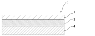
- the exterior material 10 for an electricity storage device of the present disclosure is, for example, as shown in FIG. consists of
- the base material layer 1 is the outermost layer
- the heat-fusible resin layer 4 is the innermost layer.
- the heat-sealable resin layers 4 of the electricity storage device exterior material 10 face each other, and the peripheral edges are heat-sealed.
- the electricity storage device element is accommodated in the space formed by .
- the barrier layer 3 is the reference
- the heat-fusible resin layer 4 side is inner than the barrier layer 3
- the base layer 1 side is more than the barrier layer 3. outside.
- the electrical storage device exterior material 10 is provided between the base material layer 1 and the barrier layer 3 for the purpose of improving the adhesion between these layers, if necessary. It may have an adhesive layer 2 .
- an adhesive layer 5 may optionally be provided between the barrier layer 3 and the heat-fusible resin layer 4 for the purpose of enhancing the adhesion between these layers.
- a surface coating layer 6 or the like may be provided on the outside of the base material layer 1 (on the side opposite to the heat-fusible resin layer 4 side), if necessary.
- the power storage device exterior material 1 of the present disclosure includes a water absorbing layer containing a water absorbing agent inside the barrier layer 3 .
- the heat-fusible resin layer 4, the adhesive layer 5, etc. may include a water absorbing layer.
- the thickness of the laminate that constitutes the power storage device exterior material 10 is not particularly limited, but from the viewpoint of cost reduction, energy density improvement, etc., it is, for example, 190 ⁇ m or less, preferably about 180 ⁇ m or less, about 155 ⁇ m or less, or about 120 ⁇ m or less. is mentioned.
- the thickness of the laminate constituting the power storage device exterior material 10 is preferably about 35 ⁇ m or more, about 45 ⁇ m or more, about 60 ⁇ m or more can be mentioned.
- the preferred range of the laminate constituting the power storage device exterior material 10 is, for example, about 35 to 190 ⁇ m, about 35 to 180 ⁇ m, about 35 to 155 ⁇ m, about 35 to 120 ⁇ m, about 45 to 190 ⁇ m, and about 45 to 180 ⁇ m. , about 45 to 155 ⁇ m, about 45 to 120 ⁇ m, about 60 to 190 ⁇ m, about 60 to 180 ⁇ m, about 60 to 155 ⁇ m, and about 60 to 120 ⁇ m, and particularly preferably about 60 to 155 ⁇ m.
- the power storage device exterior material 10 can be suitably applied to all-solid-state batteries.
- the thickness of the laminate constituting the power storage device exterior material 10 is not particularly limited. From the viewpoint of maintaining the function of the all-solid battery exterior material to protect the battery element, it is preferably about 10 ⁇ m or more, about 15 ⁇ m or more, about 20 ⁇ m or more, and a preferable range is, for example, 10 to about 10000 ⁇ m, about 10 to 8000 ⁇ m, about 10 to 5000 ⁇ m, about 15 to 10000 ⁇ m, about 15 to 8000 ⁇ m, about 15 to 5000 ⁇ m, about 20 to 10000 ⁇ m, about 20 to 8000 ⁇ m, about 20 to 5000 ⁇ m, particularly 200 to 5000 ⁇ m degree is preferred.
- the thickness (total thickness) of the laminate constituting the power storage device exterior material 10 is the base layer 1, the adhesive layer 2 provided as necessary, the barrier layer 3, if necessary
- the ratio of the total thickness of the adhesive layer 5, the heat-fusible resin layer 4, and the surface coating layer 6 provided as necessary is preferably 90% or more, more preferably 95% or more, More preferably, it is 98% or more.
- the electrical storage device exterior material 10 of the present disclosure includes the base material layer 1, the adhesive layer 2, the barrier layer 3, the adhesive layer 5, and the heat-fusible resin layer 4, the electrical storage device exterior
- the ratio of the total thickness of each layer to the thickness (total thickness) of the laminate constituting the material 10 is preferably 90% or more, more preferably 95% or more, and still more preferably 98% or more.
- the power storage device exterior material 10 of the present disclosure is a laminate including the base material layer 1, the adhesive layer 2, the barrier layer 3, and the heat-fusible resin layer 4, the power storage device exterior material
- the ratio of the total thickness of each of these layers to the thickness (total thickness) of the laminate constituting 10 is, for example, 80% or more, preferably 90% or more, more preferably 95% or more, and further preferably 98% or more. can be done.
- Each layer [water absorption layer] that forms the exterior material for the storage device includes a water absorption layer inside the barrier layer 3 .
- the water absorbing layer is a layer containing a water absorbing agent.
- the performance of the electricity storage device deteriorates. It is By providing the barrier layer, penetration of moisture from the outside of the barrier layer can be suppressed.
- the heat-sealable resin layer of the exterior material is heat-sealed to seal the electrical storage device element, the end face of the exterior material is exposed to the outside, and moisture is absorbed from the end face of the layer inside the barrier layer. There is a risk of intrusion.
- the layers inside the barrier layer of the exterior material absorb water before the electricity storage device element is sealed with the exterior material, the moisture in the layers inside the barrier layer is absorbed after the electricity storage device element is sealed. There is also a risk of infiltration into the electrical storage device element.
- the electrical storage device exterior material 1 includes a water absorbing layer containing a water absorbing agent inside the barrier layer 3, thereby preventing moisture from being absorbed from the end of the exterior material. It is possible to effectively suppress the infiltration and the infiltration of moisture contained in the layers inside the barrier layer, and furthermore, it is possible to absorb the moisture contained in the electricity storage device element. That is, since the power storage device exterior material 1 of the present disclosure includes a water absorbing layer containing a water absorbing agent inside the barrier layer 3, the moisture that has entered from the layers inside the barrier layer of the exterior material is absorbed by the water absorbing layer. By absorbing and retaining water, it is possible to prevent moisture from reaching the electricity storage device element, and furthermore, to absorb moisture contained in the electricity storage device element.
- the water absorbing layer is not particularly limited as long as it is located inside the barrier layer 3.
- the water-absorbing layer is preferably contained in at least one of the adhesive layer 5 and the heat-fusible resin layer 4, and more preferably contained in the heat-fusible resin layer 4, which is the innermost layer.
- the heat-fusible resin layer 4 may be composed of a single layer, or may be composed of two or more layers.
- the heat-fusible resin layer 4 includes a water absorbing layer, if the heat-fusible resin layer 4 is a single layer, the heat-fusible resin layer 4 becomes the water-absorbing layer, and the heat-fusible resin layer 4 has two or more layers.
- at least one layer becomes a water absorbing layer.
- the moisture to be absorbed is gaseous and/or liquid moisture.
- the power storage device exterior material of the present disclosure can also absorb sulfur-based gas, if necessary.
- sulfur-based gases include hydrogen sulfide, dimethyl sulfide, methyl mercaptan, and sulfur oxides represented by SOx.
- Moisture to be absorbed for example, when absorbed by a solid electrolyte type lithium ion battery, generates various outgases. It occurs in the case of an all-solid battery using a system inorganic solid electrolyte, or in the case of a lithium secondary battery in which lithium sulfur is used for the positive electrode).
- the resin contained in the water absorbing layer is not particularly limited as long as it does not impede the effects of the present disclosure. is more preferable.
- resins include resins such as polyesters, polyolefins, polyamides, epoxy resins, acrylic resins, fluororesins, polyurethanes, silicone resins and phenolic resins, and thermoplastic resins such as modified products of these resins.
- the resin contained in the water absorbing layer may be a copolymer of these resins or a modified product of the copolymer. Furthermore, it may be a mixture of these resins.
- heat-fusible resins such as polyesters and polyolefins are preferred.
- polyester examples include polyethylene terephthalate, polybutylene terephthalate, polyethylene naphthalate, polybutylene naphthalate, polyethylene isophthalate, and copolymerized polyester.
- copolyester examples include copolyester having ethylene terephthalate as a main repeating unit.
- copolymer polyester polymerized with ethylene isophthalate with ethylene terephthalate as the main repeating unit hereinafter abbreviated after polyethylene (terephthalate / isophthalate)
- polyethylene (terephthalate / adipate) polyethylene (terephthalate / sodium sulfoisophthalate)
- polyethylene (terephthalate/sodium isophthalate) polyethylene (terephthalate/phenyl-dicarboxylate), polyethylene (terephthalate/decanedicarboxylate), and the like.
- These polyesters may be used singly or in combination of two or more.
- the heat resistance and pressure resistance of the power storage device exterior material 1 (for example, deterioration in insulation when the power storage device is sealed with the power storage device exterior material 1 (due to crushing due to heat sealing)) is increased.
- polybutylene terephthalate is particularly preferred.
- the resin contained in the water absorbing layer is polybutylene terephthalate.
- polyolefins include polyethylenes such as low-density polyethylene, medium-density polyethylene, high-density polyethylene, and linear low-density polyethylene; ethylene- ⁇ -olefin copolymers; homopolypropylene and polypropylene block copolymers (for example, propylene- ⁇ -olefin copolymers; ethylene-butene-propylene terpolymers; and the like.
- the polyolefin resin is a copolymer, it may be a block copolymer or a random copolymer. These polyolefin-based resins may be used alone or in combination of two or more.
- the water-absorbing agent contained in the water-absorbing layer is not particularly limited as long as it exhibits water absorption when dispersed in the resin film.
- an inorganic water-absorbing agent can be preferably used from the viewpoint of stability over time in an electricity storage device.
- inorganic water-absorbing agents include calcium oxide, anhydrous magnesium sulfate, magnesium oxide, calcium chloride, zeolite, aluminum oxide, silica gel, alumina gel, and calcined alum.
- inorganic chemical water absorbing agents have a higher water absorbing effect than inorganic physical water absorbing agents, and it is possible to reduce the content. Easy to implement with a single layer.
- inorganic chemical water-absorbing agents calcium oxide, anhydrous magnesium sulfate, and magnesium oxide release little moisture, are highly stable over time even in low-humidity conditions inside the package, and have an absolutely dry effect.
- the absolute dry effect refers to the effect of absorbing water until the relative humidity reaches around 0%
- the humidity conditioning effect refers to the ability to absorb water when the humidity is high and release it when the humidity is low to keep the humidity constant. point to the effect.
- the resin content in the water absorbing layer is, for example, 50% by mass or more, preferably 55% by mass or more, and more preferably 60% by mass or more.
- the content of the water-absorbing agent contained in the water-absorbing layer is not particularly limited as long as the effect of the present disclosure is exhibited, and is preferably about 0.5 parts by mass or more, more preferably about 2 parts by mass or more, more preferably about 3 parts by mass or more, and preferably about 50 parts by mass or less, more preferably about 45 parts by mass or less, still more preferably 40 parts by mass.
- the preferred range of the content is about 0.5 to 50 parts by mass, about 0.5 to 45 parts by mass, about 0.5 to 40 parts by mass, about 2 to 50 parts by mass, 2 about 45 parts by mass, about 2 to 40 parts by mass, about 3 to 50 parts by mass, about 3 to 45 parts by mass, and about 3 to 40 parts by mass.
- the water-absorbing agent contained in the water-absorbing layer is preferably contained, for example, via a masterbatch obtained by melt-blending the water-absorbing agent and resin.
- a masterbatch is prepared by melt-blending a water-absorbing agent with a resin at a relatively high concentration.
- the obtained masterbatch can be further mixed with a resin and formed into a film to form a water absorbing layer.
- the content of the water absorbing agent in the masterbatch is preferably about 20 to 90% by mass, more preferably about 30 to 70% by mass. Within the above range, it is easy to include a necessary and sufficient amount of the water absorbing agent in a dispersed state in the water absorbing layer.
- the layer inside the barrier layer 3 may further contain a sulfur-based gas absorbent in addition to the water absorbing agent.
- a layer containing a sulfur-based gas absorbent may be referred to as a "sulfur-based gas absorbent layer".
- the sulfur-based gas absorbent may be included in the water absorbing layer or may be included in the layer not containing the water absorbing agent. If the layer inside the barrier layer 3 is composed of two or more layers, the sulfur-based gas absorbent is contained in a layer that does not contain a water-absorbing agent to form a sulfur-based gas absorbent layer. is preferred.
- the sulfur-based gas absorbing layer is positioned inside the barrier layer 3.
- the sulfur-based gas absorbing layer is preferably contained in at least one of the adhesive layer 5 and the heat-fusible resin layer 4, and more preferably contained in the heat-fusible resin layer 4, which is the innermost layer.
- the heat-fusible resin layer 4 may be composed of a single layer, or may be composed of two or more layers.
- the heat-fusible resin layer 4 includes a sulfur-based gas absorption layer
- the heat-fusible resin layer 4 becomes a sulfur-based gas absorption layer
- the heat-fusible resin When the layer 4 is composed of two or more layers, at least one layer is a sulfur-based gas absorbing layer.
- the sulfur-based gas absorbent preferably contains a sulfur-based gas physical absorbent and/or a sulfur-based gas chemical absorbent.
- various sulfur-based gas absorbents in combination, for example, by using a sulfur-based gas physical absorbent and a sulfur-based gas chemical absorbent together, it is possible to easily absorb various sulfur-based gases.
- a sulfur-based gas absorbent is used, for example, in the form of powder.
- the maximum particle size of the sulfur-based gas absorbent is preferably 20 ⁇ m or less, and the number average particle size of the powder is preferably 0.1 ⁇ m or more, 1.0 ⁇ m or more, and preferably 15 ⁇ m or less, 10 ⁇ m or less, 8 ⁇ m or less, etc.
- Preferred ranges include about 0.1 to 15 ⁇ m, about 0.1 to 10 ⁇ m, about 0.1 to 8 ⁇ m, about 1 to 15 ⁇ m, about 1 to 10 ⁇ m, and about 1 to 8 ⁇ m. If the number average particle size is smaller than the above range, the sulfur gas absorbent tends to aggregate. Since the surface area of the system gas absorbent becomes small, there is a possibility that sulfur system gas absorption may be inferior.
- the sulfur-based gas physical absorbent is a gas absorbent that has the action of physically absorbing the sulfur-based gas to be absorbed.
- the sulfur-based gas physical absorbent may contain one or more selected from the group consisting of hydrophobic zeolite, bentonite, and sepiolite having a SiO 2 /Al 2 O 3 molar ratio of 1/1 to 2000/1. preferable.
- a hydrophobic zeolite is a zeolite that is excellent in absorbing molecules with low polarity, such as sulfur-based gases, and has a porous structure.
- zeolite becomes more hydrophobic as the molar ratio of SiO 2 /Al 2 O 3 , which is a constituent component, becomes higher.
- the hydrophobicity increases, it becomes easier to absorb molecules with low polarity such as sulfur-based gases, and conversely, the affinity with molecules with high polarity such as water decreases, making it difficult to absorb them. .
- the SiO 2 /Al 2 O 3 molar ratio of the hydrophobic zeolite is preferably 30/1 to 10000/1, more preferably 35/1 to 9000/1, even more preferably 40/1 to 8500/1.
- Hydrophobic zeolite has high heat resistance and can maintain its absorption effect even when exposed to high temperatures of 230° C. or higher.
- a hydrophobic zeolite having a molar ratio within the above range is preferably used in view of the balance between sulfur-based gas absorption capacity and availability.
- Bentonite is an inorganic substance that contains montmorillonite, which is a clay mineral, as a main component, contains a large amount of layered aluminum phyllosilicate, and contains minerals such as quartz and feldspar as impurities.
- Bentonite includes, for example, Na-type bentonite containing many Na + ions, Ca-type bentonite containing many Ca 2+ ions, and Ca-type bentonite that is artificially converted to Na-type by adding several wt% of sodium carbonate. activated bentonite, etc.
- Sepiolite is a clay mineral whose main component is hydrated magnesium silicate, and its general chemical composition is represented by Mg 8 Si 12 O 30 (OH 2 ) 4 (OH) 4 6-8H 2 O, and is porous. have a structure.
- the pH (3% suspension) is preferably 8.0 to 9.0, more preferably 8.9 to 9.3, from the standpoint of availability.
- the sulfur-based gas chemical absorbent is a gas absorbent that has the action of chemically absorbing or decomposing the sulfur-based gas of the gas to be absorbed. Further, by chemical absorption or decomposition, it is less likely to be affected by water or the like, and once absorbed sulfur-based gas molecules are less likely to be desorbed, enabling efficient absorption. Also, the decomposition products are absorbed by sulfur-based gas physical absorbents or sulfur-based gas chemical absorbents.
- the sulfur-based gas chemical absorbent preferably contains one or more selected from the group consisting of metal oxide-supported inorganic substances, glass mixed with metal, and glass mixed with metal ions.
- the metal oxide in the metal oxide-supported inorganic material preferably contains one or more selected from the group consisting of CuO, ZnO, and AgO.
- the inorganic substance to be supported is preferably an inorganic porous material such as zeolite.
- the metal species of the metal in the metal-doped glass or the metal ion in the metal-ion-doped glass is from the group consisting of Ca, Mg, Na, Cu, Zn, Ag, Pt, Au, Fe, Al, Ni. It is preferable to include one or more selected types.
- the content of the sulfur-based gas absorbent contained in the sulfur-based gas absorption layer is not particularly limited as long as it absorbs the sulfur-based gas, and the resin 100 contained in the sulfur-based gas absorption layer It is preferably about 5 parts by mass or more, more preferably about 6 parts by mass or more, still more preferably about 7 parts by mass or more, and preferably about 60 parts by mass or less, more preferably about 55 parts by mass. parts or less, more preferably about 50 parts by mass or less, more preferably about 30 parts by mass or less.
- the sulfur-based gas absorbent contained in the sulfur-based gas absorbing layer is preferably contained via a masterbatch obtained by melt-blending the sulfur-based gas absorbent with a resin.
- a masterbatch is prepared by melt blending a sulfur-based gas absorbent with a resin at a relatively high concentration, and then the masterbatch and other materials are added so that the desired concentration in the sulfur-based gas absorbent layer is achieved. It is preferable to dry blend and use the components of.
- Each of the sulfur-based gas absorbents and resins to be melt-blended may be of one type or two or more types.
- the content of the sulfur-based gas absorbent in the masterbatch is preferably about 5 to 60% by mass, more preferably about 10 to 50% by mass. Within the above range, it is easy to contain a necessary and sufficient amount of the sulfur-based gas absorbent in a dispersed state in the sulfur-based gas absorbent layer.
- examples of the resin contained in the sulfur-based gas absorption layer are the same as the resins exemplified as the resin contained in the water absorption layer.
- the resin content in the sulfur-based gas absorbing layer is, for example, 60% by mass or more, preferably 65% by mass or more, and more preferably 70% by mass or more.
- the sulfur-based gas absorbent when the layer inside the barrier layer 3 contains the sulfur-based gas absorbent, the sulfur-based gas absorbent may be contained in the water absorbing layer, and the water absorbing agent is not included. may be included in the layer.
- the sulfur-based gas absorbent when the sulfur-based gas absorbent is contained in the water-absorbing layer, the water-absorbing layer also functions as a sulfur-based gas absorbing layer.
- the power storage device exterior material 10 includes a sulfur-based gas absorption layer inside the barrier layer 3 .
- the sulfur-based gas absorption layer is a layer containing a sulfur-based gas absorbent.
- the electricity storage device when moisture enters the inside of the electricity storage device (the electricity storage device element), sulfur-based gas is generated, the internal pressure of the electricity storage device increases, and there is concern that the electricity storage device may burst.
- the barrier layer By providing the barrier layer on the film-like exterior material, it is possible to suppress the infiltration of moisture from the outside of the barrier layer.
- the heat-sealable resin layer of the exterior material is heat-sealed to seal the electrical storage device element, the end face of the exterior material is exposed to the outside, and moisture is absorbed from the end face of the layer inside the barrier layer. There is a risk of intrusion.
- the layers inside the barrier layer of the exterior material absorb water before the electricity storage device element is sealed with the exterior material, the moisture in the layers inside the barrier layer is absorbed after the electricity storage device element is sealed. There is also a risk of infiltration into the electrical storage device elements.
- the power storage device exterior material 10 includes a sulfur-based gas absorption layer containing a sulfur-based gas absorbent inside the barrier layer 3, so that the power storage device 10 It is possible to suitably absorb the sulfur-based gas generated by the infiltration of moisture into the interior of the. That is, since the power storage device exterior material 1 of the present disclosure includes a sulfur-based gas absorption layer containing a sulfur-based gas absorbent inside the barrier layer 3, from the layer inside the barrier layer of the exterior material Even when sulfur-based gas is generated inside the electricity storage device due to infiltration, the sulfur-based gas can be absorbed and an increase in the internal pressure of the electricity storage device can be suppressed.
- the sulfur-based gas absorption layer is not particularly limited as long as it is positioned inside the barrier layer 3 .
- the sulfur-based gas absorbing layer is preferably contained in at least one of the adhesive layer 5 and the heat-fusible resin layer 4, and more preferably contained in the heat-fusible resin layer 4, which is the innermost layer.
- the heat-fusible resin layer 4 may be composed of a single layer, or may be composed of two or more layers.
- the heat-fusible resin layer 4 includes a sulfur-based gas absorption layer
- the heat-fusible resin layer 4 becomes a sulfur-based gas absorption layer
- the heat-fusible resin When the layer 4 is composed of two or more layers, at least one layer is a sulfur-based gas absorbing layer.
- examples of the sulfur-based gas to be absorbed include hydrogen sulfide, dimethyl sulfide, methyl mercaptan, and sulfur oxides represented by SOx.
- the resin film for an electricity storage device of the present disclosure can also absorb water as needed. Moisture is gaseous and/or liquid moisture. Moisture to be absorbed, for example, when absorbed by a solid electrolyte type lithium ion battery, generates various outgases. It occurs in the case of an all-solid battery using a system inorganic solid electrolyte, or in the case of a lithium secondary battery in which lithium sulfur is used for the positive electrode).
- the resin contained in the sulfur-based gas absorbing layer is not particularly limited as long as it does not impair the effects of the present disclosure. Resin is more preferred. Specific examples of resins include resins such as polyesters, polyolefins, polyamides, epoxy resins, acrylic resins, fluororesins, polyurethanes, silicone resins and phenolic resins, and thermoplastic resins such as modified products of these resins. Further, the resin contained in the sulfur-based gas absorbing layer may be a copolymer of these resins or a modified copolymer thereof. Furthermore, it may be a mixture of these resins. Among these, heat-fusible resins such as polyesters and polyolefins are preferred.
- polyester examples include polyethylene terephthalate, polybutylene terephthalate, polyethylene naphthalate, polybutylene naphthalate, polyethylene isophthalate, and copolymerized polyester.
- copolyester examples include copolyester having ethylene terephthalate as a main repeating unit.
- copolymer polyester polymerized with ethylene isophthalate with ethylene terephthalate as the main repeating unit hereinafter abbreviated after polyethylene (terephthalate / isophthalate)
- polyethylene (terephthalate / adipate) polyethylene (terephthalate / sodium sulfoisophthalate)
- polyethylene (terephthalate/sodium isophthalate) polyethylene (terephthalate/phenyl-dicarboxylate), polyethylene (terephthalate/decanedicarboxylate), and the like.
- These polyesters may be used singly or in combination of two or more.
- the heat resistance and pressure resistance of the power storage device exterior material 10 (for example, the decrease in insulation when the power storage device is sealed with the power storage device exterior material 10 (due to crushing due to heat sealing)) is suppressed.
- polybutylene terephthalate is particularly preferred from the viewpoint of Moreover, when the heat-fusible resin layer 4 includes a sulfur-based gas absorbing layer, the resin included in the sulfur-based gas absorbing layer is polybutylene terephthalate.
- polyolefins include polyethylenes such as low-density polyethylene, medium-density polyethylene, high-density polyethylene, and linear low-density polyethylene; ethylene- ⁇ -olefin copolymers; homopolypropylene and polypropylene block copolymers (for example, propylene- ⁇ -olefin copolymers; ethylene-butene-propylene terpolymers; and the like.
- the polyolefin resin is a copolymer, it may be a block copolymer or a random copolymer. These polyolefin-based resins may be used alone or in combination of two or more.
- the sulfur-based gas absorbent preferably contains a sulfur-based gas physical absorbent and/or a sulfur-based gas chemical absorbent.
- various sulfur-based gas absorbents in combination, for example, by using a sulfur-based gas physical absorbent and a sulfur-based gas chemical absorbent together, it is possible to easily absorb various sulfur-based gases.
- a sulfur-based gas absorbent is used, for example, in the form of powder.
- the maximum particle size of the sulfur-based gas absorbent is preferably 20 ⁇ m or less, and the number average particle size of the powder is preferably 0.1 ⁇ m or more and 15 ⁇ m or less. If the number average particle size is smaller than the above range, the sulfur gas absorbent tends to aggregate. Since the surface area of the system gas absorbent becomes small, there is a possibility that sulfur system gas absorption may be inferior.
- the sulfur-based gas physical absorbent is a gas absorbent that has the action of physically absorbing the sulfur-based gas to be absorbed.
- the sulfur-based gas physical absorbent may contain one or more selected from the group consisting of hydrophobic zeolite, bentonite, and sepiolite having a SiO 2 /Al 2 O 3 molar ratio of 1/1 to 2000/1. preferable.
- hydrophobic zeolite bentonite, and sepiolite are the same as those described in the first aspect, and will not be described.
- the sulfur-based gas chemical absorbent is a gas absorbent that has the action of chemically absorbing or decomposing the sulfur-based gas of the gas to be absorbed. Further, by chemical absorption or decomposition, it is less likely to be affected by water or the like, and once absorbed sulfur-based gas molecules are less likely to be desorbed, enabling efficient absorption. Also, the decomposition products are absorbed by sulfur-based gas physical absorbents or sulfur-based gas chemical absorbents.
- the sulfur-based gas chemical absorbent preferably contains one or more selected from the group consisting of metal oxide-supported inorganic substances, glass mixed with metal, and glass mixed with metal ions.
- the metal oxide in the metal oxide-supported inorganic material preferably contains one or more selected from the group consisting of CuO, ZnO, and AgO.
- the inorganic substance to be supported is preferably an inorganic porous material such as zeolite.
- the metal species of the metal in the metal-doped glass or the metal ion in the metal-ion-doped glass is from the group consisting of Ca, Mg, Na, Cu, Zn, Ag, Pt, Au, Fe, Al, Ni. It is preferable to include one or more selected types.
- the content of the sulfur-based gas absorbent contained in the sulfur-based gas absorption layer is not particularly limited as long as it absorbs the sulfur-based gas, and the resin 100 contained in the sulfur-based gas absorption layer It is preferably about 5 parts by mass or more, more preferably about 6 parts by mass or more, still more preferably about 7 parts by mass or more, and preferably about 60 parts by mass or less, more preferably about 55 parts by mass. parts or less, more preferably about 50 parts by mass or less, more preferably about 30 parts by mass or less.
- the sulfur-based gas absorbent contained in the sulfur-based gas absorbing layer is preferably contained via a masterbatch obtained by melt-blending the sulfur-based gas absorbent with a resin.
- a masterbatch is prepared by melt blending a sulfur-based gas absorbent with a resin at a relatively high concentration, and then the masterbatch and other materials are added so that the desired concentration in the sulfur-based gas absorbent layer is achieved. It is preferable to dry blend and use the components of.
- Each of the sulfur-based gas absorbents and resins to be melt-blended may be of one type or two or more types.
- the content of the sulfur-based gas absorbent in the masterbatch is preferably about 5 to 70% by mass, more preferably about 10 to 60% by mass. Within the above range, it is easy to contain a necessary and sufficient amount of the sulfur-based gas absorbent in a dispersed state in the sulfur-based gas absorbent layer.
- the layer inside the barrier layer 3 may further contain a water absorbing agent in addition to the sulfur-based gas absorbent.
- the layer containing the water-absorbing agent may be referred to as the "water-absorbing layer".
- the water-absorbing agent when a water-absorbing layer is included, the water-absorbing agent may be included in the sulfur-based gas-absorbing layer, or may be included in a layer containing no sulfur-based gas absorbent. If the layer inside the barrier layer 3 is composed of two or more layers, it is preferable that the water absorbing agent is contained in a layer that does not contain the sulfur-based gas absorbent to constitute the water absorbing layer.
- the resin content in the sulfur-based gas absorbing layer is, for example, 40% by mass or more, preferably 45% by mass or more, and more preferably 50% by mass or more.
- the water-absorbing agent contained in the water-absorbing layer is not particularly limited as long as it exhibits water absorption when dispersed in the resin film.
- an inorganic water-absorbing agent can be preferably used from the viewpoint of stability over time in an electricity storage device.
- Preferable specific examples of inorganic water-absorbing agents include calcium oxide, anhydrous magnesium sulfate, magnesium oxide, calcium chloride, zeolite, aluminum oxide, silica gel, alumina gel, and calcined alum.
- inorganic chemical water absorbing agents have a higher water absorbing effect than inorganic physical water absorbing agents, and it is possible to reduce the content. Easy to implement with a single layer.
- inorganic chemical water-absorbing agents calcium oxide, anhydrous magnesium sulfate, and magnesium oxide release little moisture, are highly stable over time even in low-humidity conditions inside the package, and have an absolutely dry effect.
- the absolute dry effect refers to the effect of absorbing water until the relative humidity reaches around 0%
- the humidity conditioning effect refers to the ability to absorb water when the humidity is high and release it when the humidity is low to keep the humidity constant. point to the effect.
- an inorganic chemical absorbent having a high temperature range in which moisture is re-released is preferable.
- the content of the water-absorbing agent contained in the water-absorbing layer is not particularly limited as long as the effect of the present disclosure is exhibited, and is preferably about 0.5 parts by mass or more, more preferably about 2 parts by mass or more, more preferably about 3 parts by mass or more, and preferably about 50 parts by mass or less, more preferably about 45 parts by mass or less, still more preferably 40 parts by mass.
- the preferred range of the content is about 0.5 to 50 parts by mass, about 0.5 to 45 parts by mass, about 0.5 to 40 parts by mass, about 2 to 50 parts by mass, 2 about 45 parts by mass, about 2 to 40 parts by mass, about 3 to 50 parts by mass, about 3 to 45 parts by mass, and about 3 to 40 parts by mass.
- the water-absorbing agent contained in the water-absorbing layer is preferably contained, for example, via a masterbatch obtained by melt-blending the water-absorbing agent and resin.
- a masterbatch is prepared by melt-blending a water-absorbing agent with a resin at a relatively high concentration.
- the obtained masterbatch can be further mixed with a resin and formed into a film to form a water absorbing layer.
- the content of the water absorbing agent in the masterbatch is preferably about 20 to 90% by mass, more preferably about 30 to 70% by mass. Within the above range, it is easy to include a necessary and sufficient amount of the water absorbing agent in a dispersed state in the water absorbing layer.
- the layer inside the barrier layer 3 further contains a water-absorbing agent in addition to the sulfur-based gas absorbent
- the water-absorbing layer is positioned inside the barrier layer 3.
- the water-absorbing layer is preferably contained in at least one of the adhesive layer 5 and the heat-fusible resin layer 4, and more preferably contained in the heat-fusible resin layer 4, which is the innermost layer.
- the heat-fusible resin layer 4 may be composed of a single layer, or may be composed of two or more layers.
- the heat-fusible resin layer 4 includes a water absorbing layer
- the heat-fusible resin layer 4 becomes the water-absorbing layer
- the heat-fusible resin layer 4 has two or more layers.
- at least one layer becomes a water absorbing layer.
- examples of the resin contained in the water absorption layer are the same as the resins exemplified as the resin contained in the sulfur-based gas absorption layer.
- the resin content in the water absorbing layer is, for example, 50% by mass or more, preferably 55% by mass or more, and more preferably 60% by mass or more.
- the water absorbing agent when the water absorbing agent is contained in the layer inside the barrier layer 3, the water absorbing agent may be contained in the sulfur-based gas absorbing layer, and the sulfur-based gas absorbing agent is not included. may be included in the layer.
- the sulfur-based gas absorption layer When the water absorbing agent is contained in the sulfur-based gas absorption layer, the sulfur-based gas absorption layer also functions as a water absorption layer.
- the base material layer 1 is a layer provided for the purpose of exhibiting a function as a base material of an exterior material for an electric storage device.
- the base material layer 1 is located on the outer layer side of the exterior material for electrical storage devices.
- the material forming the base material layer 1 is not particularly limited as long as it functions as a base material, that is, at least has insulating properties.
- the base material layer 1 can be formed using, for example, a resin, and the resin may contain additives described later.
- the substrate layer 1 can be made of, for example, a resin film made of resin.
- the base material layer 1 is formed of a resin film
- the resin forming the base material layer 1 may be formed into a film on the surface of the barrier layer 3 or the like by extrusion molding or coating to form the base material layer 1 formed of a resin film. , or may be formed by applying a resin.
- the resin film may be an unstretched film or a stretched film.
- stretched films include uniaxially stretched films and biaxially stretched films, with biaxially stretched films being preferred.
- stretching methods for forming a biaxially stretched film include successive biaxial stretching, inflation, and simultaneous biaxial stretching.
- Methods for applying the resin include a roll coating method, a gravure coating method, an extrusion coating method, and the like.
- resins forming the base material layer 1 include resins such as polyester, polyamide, polyolefin, epoxy resin, acrylic resin, fluororesin, polyurethane, silicon resin, phenolic resin, and modified products of these resins. Further, the resin forming the base material layer 1 may be a copolymer of these resins or a modified product of the copolymer. Furthermore, it may be a mixture of these resins.
- the base material layer 1 preferably contains these resins as a main component, and more preferably contains polyester or polyamide as a main component.
- the main component is, among the resin components contained in the base layer 1, a content of, for example, 50% by mass or more, preferably 60% by mass or more, more preferably 70% by mass or more, and still more preferably 80% by mass. % or more, more preferably 90 mass % or more, more preferably 95 mass % or more, still more preferably 98 mass % or more, still more preferably 99 mass % or more.
- the base layer 1 containing polyester or polyamide as a main component means that the content of polyester or polyamide among the resin components contained in the base layer 1 is, for example, 50% by mass or more, preferably 60% by mass.
- % or more more preferably 70 mass % or more, still more preferably 80 mass % or more, still more preferably 90 mass % or more, still more preferably 95 mass % or more, still more preferably 98 mass % or more, still more preferably 99 mass % or more means that
- the resin forming the base material layer 1 is preferably polyester or polyamide, more preferably polyester (especially polyethylene terephthalate).
- polyester examples include polyethylene terephthalate, polybutylene terephthalate, polyethylene naphthalate, polybutylene naphthalate, polyethylene isophthalate, and copolymerized polyester.
- copolyester examples include copolyester having ethylene terephthalate as a main repeating unit.
- copolymer polyester polymerized with ethylene isophthalate with ethylene terephthalate as the main repeating unit hereinafter abbreviated after polyethylene (terephthalate / isophthalate)
- polyethylene (terephthalate / adipate) polyethylene (terephthalate / sodium sulfoisophthalate)
- polyethylene (terephthalate/sodium isophthalate) polyethylene (terephthalate/phenyl-dicarboxylate), polyethylene (terephthalate/decanedicarboxylate), and the like.
- These polyesters may be used singly or in combination of two or more.
- polyamide specifically, aliphatic polyamide such as nylon 6, nylon 66, nylon 610, nylon 12, nylon 46, copolymer of nylon 6 and nylon 66; terephthalic acid and / or isophthalic acid Hexamethylenediamine-isophthalic acid-terephthalic acid copolymer polyamide such as nylon 6I, nylon 6T, nylon 6IT, nylon 6I6T (I represents isophthalic acid, T represents terephthalic acid) containing structural units derived from, polyamide MXD6 (polymetallic Polyamides containing aromatics such as silylene adipamide); alicyclic polyamides such as polyamide PACM6 (polybis(4-aminocyclohexyl)methane adipamide); Copolymerized polyamides, polyesteramide copolymers and polyetheresteramide copolymers which are copolymers of copolymerized polyamides with polyesters or polyalkylene ether glycols; and polyamides such
- the substrate layer 1 preferably includes at least one of a polyester film, a polyamide film, and a polyolefin film, preferably includes at least one of a stretched polyester film, a stretched polyamide film, and a stretched polyolefin film, More preferably, at least one of an oriented polyethylene terephthalate film, an oriented polybutylene terephthalate film, an oriented nylon film, and an oriented polypropylene film is included, and the biaxially oriented polyethylene terephthalate film, biaxially oriented polybutylene terephthalate film, and biaxially oriented nylon film , biaxially oriented polypropylene film.
- the base material layer 1 may be a single layer, or may be composed of two or more layers.
- the substrate layer 1 may be a laminate obtained by laminating resin films with an adhesive or the like, or may be formed by co-extrusion of resin to form two or more layers. It may also be a laminate of resin films. A laminate of two or more resin films formed by coextrusion of resin may be used as the base material layer 1 without being stretched, or may be used as the base material layer 1 by being uniaxially or biaxially stretched.
- the laminate of two or more resin films in the substrate layer 1 include a laminate of a polyester film and a nylon film, a laminate of nylon films of two or more layers, and a laminate of polyester films of two or more layers. etc., preferably a laminate of a stretched nylon film and a stretched polyester film, a laminate of two or more layers of stretched nylon films, and a laminate of two or more layers of stretched polyester films.
- the substrate layer 1 is a laminate of two layers of resin films, a laminate of polyester resin films and polyester resin films, a laminate of polyamide resin films and polyamide resin films, or a laminate of polyester resin films and polyamide resin films.
- a laminate is preferred, and a laminate of polyethylene terephthalate film and polyethylene terephthalate film, a laminate of nylon film and nylon film, or a laminate of polyethylene terephthalate film and nylon film is more preferred.
- the polyester resin is resistant to discoloration when, for example, an electrolytic solution adheres to the surface. It is preferably located in the outermost layer.
- the two or more layers of resin films may be laminated via an adhesive.
- Preferred adhesives are the same as those exemplified for the adhesive layer 2 described later.
- the method for laminating two or more layers of resin films is not particularly limited, and known methods can be employed. Examples thereof include dry lamination, sandwich lamination, extrusion lamination, thermal lamination, and the like. A lamination method is mentioned.
- the thickness of the adhesive is, for example, about 2 to 5 ⁇ m.
- an anchor coat layer may be formed on the resin film and laminated. Examples of the anchor coat layer include the same adhesives as those exemplified for the adhesive layer 2 described later. At this time, the thickness of the anchor coat layer is, for example, about 0.01 to 1.0 ⁇ m.
- At least one of the surface and the inside of the substrate layer 1 may contain additives such as lubricants, flame retardants, antiblocking agents, antioxidants, light stabilizers, tackifiers, and antistatic agents. good. Only one type of additive may be used, or two or more types may be mixed and used.
- a lubricant exists on the surface of the base material layer 1 from the viewpoint of improving the moldability of the exterior material for an electricity storage device.
- the lubricant is not particularly limited, but preferably includes an amide-based lubricant.
- Specific examples of amide lubricants include saturated fatty acid amides, unsaturated fatty acid amides, substituted amides, methylolamides, saturated fatty acid bisamides, unsaturated fatty acid bisamides, fatty acid ester amides, and aromatic bisamides.
- saturated fatty acid amides include lauric acid amide, palmitic acid amide, stearic acid amide, behenic acid amide, and hydroxystearic acid amide.
- unsaturated fatty acid amides include oleic acid amide and erucic acid amide.
- substituted amides include N-oleyl palmitic acid amide, N-stearyl stearic acid amide, N-stearyl oleic acid amide, N-oleyl stearic acid amide, N-stearyl erucic acid amide and the like.
- methylolamide include methylol stearamide.
- saturated fatty acid bisamides include methylenebisstearic acid amide, ethylenebiscapric acid amide, ethylenebislauric acid amide, ethylenebisstearic acid amide, ethylenebishydroxystearic acid amide, ethylenebisbehenic acid amide, hexamethylenebisstearin. acid amide, hexamethylenebisbehenamide, hexamethylenehydroxystearic acid amide, N,N'-distearyladipic acid amide, N,N'-distearylsebacic acid amide and the like.
- unsaturated fatty acid bisamides include ethylenebisoleic acid amide, ethylenebiserucic acid amide, hexamethylenebisoleic acid amide, N,N'-dioleyladipic acid amide, and N,N'-dioleylsebacic acid amide. etc.
- fatty acid ester amides include stearamide ethyl stearate.
- aromatic bisamide include m-xylylenebisstearic acid amide, m-xylylenebishydroxystearic acid amide, N,N'-distearyl isophthalic acid amide and the like.
- Lubricants may be used singly or in combination of two or more.
- a lubricant exists on the surface of the base material layer 1, its amount is not particularly limited, but is preferably about 3 mg/m 2 or more, more preferably about 4 to 15 mg/m 2 , and still more preferably 5 to 14 mg. / m 2 degree.
- the lubricant present on the surface of the substrate layer 1 may be obtained by exuding the lubricant contained in the resin constituting the substrate layer 1, or by coating the surface of the substrate layer 1 with the lubricant.
- the thickness of the base material layer 1 is not particularly limited as long as it functions as a base material, but it is, for example, about 3 to 50 ⁇ m, preferably about 10 to 35 ⁇ m.
- the thickness of each resin film constituting each layer is preferably about 2 to 25 ⁇ m.
- the adhesive layer 2 is a layer provided between the base layer 1 and the barrier layer 3 as necessary for the purpose of enhancing the adhesiveness between them.
- the adhesive layer 2 is made of an adhesive that can bond the base material layer 1 and the barrier layer 3 together.
- the adhesive used to form the adhesive layer 2 is not limited, but may be any of a chemical reaction type, a solvent volatilization type, a hot melt type, a hot pressure type, and the like. Further, it may be a two-liquid curing adhesive (two-liquid adhesive), a one-liquid curing adhesive (one-liquid adhesive), or a resin that does not involve a curing reaction. Further, the adhesive layer 2 may be a single layer or multiple layers.
- the adhesive component contained in the adhesive include polyesters such as polyethylene terephthalate, polybutylene terephthalate, polyethylene naphthalate, polybutylene naphthalate, polyethylene isophthalate, and copolymerized polyester; polyether; polyurethane; epoxy resin; Phenolic resins; polyamides such as nylon 6, nylon 66, nylon 12, and copolymerized polyamides; polyolefin resins such as polyolefins, cyclic polyolefins, acid-modified polyolefins, and acid-modified cyclic polyolefins; polyvinyl acetate; cellulose; (meth)acrylic resins; polyimide; polycarbonate; amino resin such as urea resin and melamine resin; rubber such as chloroprene rubber, nitrile rubber and styrene-butadiene rubber; These adhesive components may be used singly or in combination of two or more.
- polyurethane adhesives are preferred.
- an appropriate curing agent can be used in combination with these adhesive component resins to increase the adhesive strength.
- the curing agent is selected from among polyisocyanates, polyfunctional epoxy resins, oxazoline group-containing polymers, polyamine resins, acid anhydrides, etc., depending on the functional groups of the adhesive component.
- polyurethane adhesives examples include polyurethane adhesives containing a first agent containing a polyol compound and a second agent containing an isocyanate compound.
- Preferred examples include a two-component curing type polyurethane adhesive comprising a polyol such as polyester polyol, polyether polyol, and acrylic polyol as the first agent and an aromatic or aliphatic polyisocyanate as the second agent.
- polyurethane adhesives include polyurethane adhesives containing an isocyanate compound and a polyurethane compound obtained by reacting a polyol compound and an isocyanate compound in advance.
- polyurethane adhesives examples include polyurethane adhesives containing a polyurethane compound obtained by reacting a polyol compound and an isocyanate compound in advance and a polyol compound.
- polyurethane adhesives examples include polyurethane adhesives obtained by reacting a polyurethane compound obtained by reacting a polyol compound and an isocyanate compound in advance with moisture in the air and then curing the compound.
- the polyol compound it is preferable to use a polyester polyol having a hydroxyl group in a side chain in addition to the terminal hydroxyl group of the repeating unit.
- the second agent examples include aliphatic, alicyclic, aromatic, and araliphatic isocyanate compounds.
- isocyanate compounds include hexamethylene diisocyanate (HDI), xylylene diisocyanate (XDI), isophorone diisocyanate (IPDI), hydrogenated XDI (H6XDI), hydrogenated MDI (H12MDI), tolylene diisocyanate (TDI), and diphenylmethane diisocyanate. (MDI), naphthalene diisocyanate (NDI), and the like.
- polyfunctional isocyanate-modified products of one or more of these diisocyanates are also included.
- a polymer for example, a trimer
- Such multimers include adducts, biurets, nurates and the like. Since the adhesive layer 2 is formed of a polyurethane adhesive, the exterior material for an electric storage device is imparted with excellent electrolyte resistance, and even if the electrolyte adheres to the side surface, the base layer 1 is suppressed from being peeled off. .
- the adhesive layer 2 may contain other components as long as they do not impede adhesion, and may contain colorants, thermoplastic elastomers, tackifiers, fillers, and the like. Since the adhesive layer 2 contains a coloring agent, the exterior material for an electric storage device can be colored. Known substances such as pigments and dyes can be used as the colorant. In addition, only one type of colorant may be used, or two or more types may be mixed and used.
- the type of pigment is not particularly limited as long as it does not impair the adhesiveness of the adhesive layer 2.
- organic pigments include azo-based, phthalocyanine-based, quinacridone-based, anthraquinone-based, dioxazine-based, indigothioindigo-based, perinone-perylene-based, isoindolenine-based, and benzimidazolone-based pigments.
- pigments include carbon black, titanium oxide, cadmium, lead, chromium oxide, and iron pigments, as well as fine powder of mica and fish scale foil.
- carbon black is preferable, for example, in order to make the external appearance of the exterior material for a power storage device black.
- the average particle size of the pigment is not particularly limited, and is, for example, about 0.05 to 5 ⁇ m, preferably about 0.08 to 2 ⁇ m.
- the average particle size of the pigment is the median size measured with a laser diffraction/scattering particle size distribution analyzer.
- the content of the pigment in the adhesive layer 2 is not particularly limited as long as the power storage device exterior material is colored, and is, for example, about 5 to 60% by mass, preferably 10 to 40% by mass.
- the thickness of the adhesive layer 2 is not particularly limited as long as the substrate layer 1 and the barrier layer 3 can be adhered, but is, for example, about 1 ⁇ m or more, or about 2 ⁇ m or more. Moreover, the thickness of the adhesive layer 2 is, for example, about 10 ⁇ m or less, or about 5 ⁇ m or less. Moreover, the preferable range of the thickness of the adhesive layer 2 is about 1 to 10 ⁇ m, about 1 to 5 ⁇ m, about 2 to 10 ⁇ m, and about 2 to 5 ⁇ m.
- the colored layer is a layer provided as necessary between the base layer 1 and the barrier layer 3 (not shown).
- a colored layer may be provided between the base material layer 1 and the adhesive layer 2 and between the adhesive layer 2 and the barrier layer 3 . Further, a colored layer may be provided outside the base material layer 1 . By providing the colored layer, the exterior material for an electricity storage device can be colored.
- the colored layer can be formed, for example, by applying ink containing a coloring agent to the surface of the base material layer 1 or the surface of the barrier layer 3 .
- a coloring agent such as pigments and dyes can be used as the colorant.
- only one type of colorant may be used, or two or more types may be mixed and used.
- colorant contained in the colored layer are the same as those exemplified in the [Adhesive layer 2] column.
- the barrier layer 3 is a layer that at least prevents permeation of moisture.
- the barrier layer 3 examples include a metal foil, vapor deposition film, and resin layer having barrier properties.
- vapor-deposited films include metal vapor-deposited films, inorganic oxide vapor-deposited films, and carbon-containing inorganic oxide vapor-deposited films.
- the barrier layer 3 may also include a resin film provided with at least one of these deposited films and resin layers.
- a plurality of barrier layers 3 may be provided.
- the barrier layer 3 preferably includes a layer made of a metal material. Specific examples of the metal material that constitutes the barrier layer 3 include aluminum alloys, stainless steels, titanium steels, and steel plates. When used as a metal foil, at least one of an aluminum alloy foil and a stainless steel foil is included. is preferred.
- the aluminum alloy foil is more preferably a soft aluminum alloy foil made of, for example, an annealed aluminum alloy, from the viewpoint of improving the formability of the exterior material for an electricity storage device, and from the viewpoint of further improving the formability. Therefore, it is preferably an aluminum alloy foil containing iron.
- the iron content is preferably 0.1 to 9.0% by mass, more preferably 0.5 to 2.0% by mass.
- the iron content is 0.1% by mass or more, it is possible to obtain an exterior material for an electricity storage device having superior moldability.
- the iron content is 9.0% by mass or less, it is possible to obtain an exterior material for an electricity storage device that is more excellent in flexibility.
- the soft aluminum alloy foil for example, an aluminum alloy having a composition specified by JIS H4160: 1994 A8021H-O, JIS H4160: 1994 A8079H-O, JIS H4000: 2014 A8021P-O, or JIS H4000: 2014 A8079P-O foil.
- silicon, magnesium, copper, manganese, etc. may be added as needed.
- softening can be performed by annealing treatment or the like.
- stainless steel foils include austenitic, ferritic, austenitic/ferritic, martensitic, and precipitation hardened stainless steel foils. Furthermore, from the viewpoint of providing an exterior material for an electricity storage device with excellent formability, the stainless steel foil is preferably made of austenitic stainless steel.
- austenitic stainless steel that constitutes the stainless steel foil
- SUS304 is particularly preferable.
- the thickness of the barrier layer 3 should be at least as long as it functions as a barrier layer that suppresses the intrusion of moisture.
- the thickness of the barrier layer 3 is preferably about 85 ⁇ m or less, more preferably about 50 ⁇ m or less, even more preferably about 40 ⁇ m or less, particularly preferably about 35 ⁇ m or less.
- the thickness of the barrier layer 3 is preferably about 10 ⁇ m or more, more preferably about 20 ⁇ m or more, and more preferably about 25 ⁇ m or more.
- the preferred range of thickness of the barrier layer 3 is about 10 to 85 ⁇ m, about 10 to 50 ⁇ m, about 10 to 40 ⁇ m, about 10 to 35 ⁇ m, about 20 to 85 ⁇ m, about 20 to 50 ⁇ m, about 20 to 40 ⁇ m, 20 to 40 ⁇ m. About 35 ⁇ m, about 25 to 85 ⁇ m, about 25 to 50 ⁇ m, about 25 to 40 ⁇ m, and about 25 to 35 ⁇ m.
- the thickness of the barrier layer 3 is preferably about 45 ⁇ m or more, more preferably about 45 ⁇ m or more, from the viewpoint of imparting high moldability and high rigidity to the power storage device exterior material 10 .
- the high moldability of the electrical storage device exterior material 10 facilitates deep drawing, which can contribute to increasing the capacity of the electrical storage device. Further, when the capacity of the power storage device is increased, the weight of the power storage device increases, but the rigidity of the power storage device exterior material 10 is increased, which contributes to the high sealing performance of the power storage device.
- the thickness of the stainless steel foil is preferably about 60 ⁇ m or less, more preferably about 50 ⁇ m or less, even more preferably about 40 ⁇ m or less, and even more preferably about 30 ⁇ m. Below, it is particularly preferably about 25 ⁇ m or less. Also, the thickness of the stainless steel foil is preferably about 10 ⁇ m or more, more preferably about 15 ⁇ m or more. In addition, the preferable range of the thickness of the stainless steel foil is about 10 to 60 ⁇ m, about 10 to 50 ⁇ m, about 10 to 40 ⁇ m, about 10 to 30 ⁇ m, about 10 to 25 ⁇ m, about 15 to 60 ⁇ m, about 15 to 50 ⁇ m, 15 to 50 ⁇ m. About 40 ⁇ m, about 15 to 30 ⁇ m, and about 15 to 25 ⁇ m can be mentioned.
- the barrier layer 3 is a metal foil, it is preferable that at least the surface opposite to the base layer is provided with a corrosion-resistant film in order to prevent dissolution and corrosion.
- the barrier layer 3 may be provided with a corrosion resistant coating on both sides.
- the corrosion-resistant film includes, for example, hydrothermal transformation treatment such as boehmite treatment, chemical conversion treatment, anodizing treatment, plating treatment such as nickel and chromium, and corrosion prevention treatment such as applying a coating agent to the surface of the barrier layer. It is a thin film that provides corrosion resistance (for example, acid resistance, alkali resistance, etc.) to the barrier layer.
- the corrosion-resistant film specifically means a film that improves the acid resistance of the barrier layer (acid-resistant film), a film that improves the alkali resistance of the barrier layer (alkali-resistant film), and the like.
- the treatment for forming the corrosion-resistant film one type may be performed, or two or more types may be used in combination. Also, not only one layer but also multiple layers can be used.
- the hydrothermal transformation treatment and the anodizing treatment are treatments in which the surface of the metal foil is dissolved with a treating agent to form a metal compound having excellent corrosion resistance. These treatments are sometimes included in the definition of chemical conversion treatment.
- the barrier layer 3 includes the corrosion-resistant film.
- the corrosion-resistant coating prevents delamination between the barrier layer (e.g., aluminum alloy foil) and the substrate layer during the molding of the exterior material for power storage devices, and the hydrogen fluoride generated by the reaction between the electrolyte and moisture. , the dissolution and corrosion of the barrier layer surface, especially when the barrier layer is an aluminum alloy foil, the aluminum oxide present on the barrier layer surface is prevented from dissolving and corroding, and the adhesion (wettability) of the barrier layer surface is improved. , and exhibits the effect of preventing delamination between the base material layer and the barrier layer during heat sealing and preventing delamination between the base material layer and the barrier layer during molding.
- the barrier layer e.g., aluminum alloy foil
- corrosion-resistant coatings formed by chemical conversion treatment are known, and are mainly composed of at least one of phosphates, chromates, fluorides, triazinethiol compounds, and rare earth oxides. and corrosion-resistant coatings containing.
- Examples of chemical conversion treatments using phosphate and chromate include chromic acid chromate treatment, phosphoric acid chromate treatment, phosphoric acid-chromate treatment, and chromate treatment.
- Examples of compounds include chromium nitrate, chromium fluoride, chromium sulfate, chromium acetate, chromium oxalate, chromium biphosphate, chromium acetyl acetate, chromium chloride, potassium chromium sulfate, and the like.
- Phosphorus compounds used for these treatments include sodium phosphate, potassium phosphate, ammonium phosphate, polyphosphoric acid, and the like.
- Examples of the chromate treatment include etching chromate treatment, electrolytic chromate treatment, coating-type chromate treatment, etc., and coating-type chromate treatment is preferred.
- the inner layer side surface of the barrier layer (for example, aluminum alloy foil) is first subjected to a well-known method such as an alkali immersion method, an electrolytic cleaning method, an acid cleaning method, an electrolytic acid cleaning method, an acid activation method, or the like.
- metal phosphate such as Cr (chromium) phosphate, Ti (titanium) phosphate, Zr (zirconium) phosphate, Zn (zinc) phosphate is applied to the degreased surface.
- a processing solution mainly composed of a salt and a mixture of these metal salts a processing solution mainly composed of a non-metal phosphate salt and a mixture of these non-metal salts, or a mixture of these and a synthetic resin.
- This is a treatment in which a treatment liquid composed of a mixture is applied by a well-known coating method such as a roll coating method, a gravure printing method, or an immersion method, and then dried.
- Various solvents such as water, alcohol-based solvents, hydrocarbon-based solvents, ketone-based solvents, ester-based solvents, and ether-based solvents can be used as the treatment liquid, and water is preferred.
- the resin component used at this time includes polymers such as phenolic resins and acrylic resins. and the chromate treatment used.
- the repeating units represented by the following general formulas (1) to (4) may be contained singly or in any combination of two or more. good too.
- the acrylic resin is polyacrylic acid, acrylic acid methacrylic acid ester copolymer, acrylic acid maleic acid copolymer, acrylic acid styrene copolymer, or derivatives thereof such as sodium salts, ammonium salts, and amine salts. is preferred.
- derivatives of polyacrylic acid such as ammonium salt, sodium salt or amine salt of polyacrylic acid are preferred.
- polyacrylic acid means a polymer of acrylic acid.
- the acrylic resin is preferably a copolymer of acrylic acid and dicarboxylic acid or dicarboxylic anhydride, and the ammonium salt, sodium salt, Alternatively, it is also preferably an amine salt. Only one type of acrylic resin may be used, or two or more types may be mixed and used.
- X represents a hydrogen atom, hydroxy group, alkyl group, hydroxyalkyl group, allyl group or benzyl group.
- R 1 and R 2 are the same or different and represent a hydroxy group, an alkyl group or a hydroxyalkyl group.
- alkyl groups represented by X, R 1 and R 2 in general formulas (1) to (4) include methyl group, ethyl group, n-propyl group, isopropyl group, n-butyl group, isobutyl group, A linear or branched alkyl group having 1 to 4 carbon atoms such as a tert-butyl group can be mentioned.
- hydroxyalkyl groups represented by X, R 1 and R 2 include hydroxymethyl group, 1-hydroxyethyl group, 2-hydroxyethyl group, 1-hydroxypropyl group, 2-hydroxypropyl group, 3- A straight or branched chain having 1 to 4 carbon atoms substituted with one hydroxy group such as hydroxypropyl group, 1-hydroxybutyl group, 2-hydroxybutyl group, 3-hydroxybutyl group and 4-hydroxybutyl group An alkyl group is mentioned.
- the alkyl groups and hydroxyalkyl groups represented by X, R 1 and R 2 may be the same or different.
- X is preferably a hydrogen atom, a hydroxy group or a hydroxyalkyl group.
- the number average molecular weight of the aminated phenol polymer having repeating units represented by formulas (1) to (4) is, for example, preferably about 500 to 1,000,000, more preferably about 1,000 to 20,000. more preferred.
- the aminated phenol polymer is produced, for example, by polycondensing a phenol compound or naphthol compound and formaldehyde to produce a polymer comprising repeating units represented by the general formula (1) or general formula (3), followed by formaldehyde. and an amine (R 1 R 2 NH) to introduce a functional group (--CH 2 NR 1 R 2 ) into the polymer obtained above.
- An aminated phenol polymer is used individually by 1 type or in mixture of 2 or more types.
- the corrosion-resistant film is formed by a coating-type corrosion prevention treatment in which a coating agent containing at least one selected from the group consisting of rare earth element oxide sol, anionic polymer, and cationic polymer is applied.
- a thin film that is The coating agent may further contain phosphoric acid or a phosphate, a cross-linking agent for cross-linking the polymer.
- rare earth element oxide sol rare earth element oxide fine particles (for example, particles having an average particle size of 100 nm or less) are dispersed in a liquid dispersion medium.
- rare earth element oxides include cerium oxide, yttrium oxide, neodymium oxide, and lanthanum oxide, and cerium oxide is preferable from the viewpoint of further improving adhesion.
- the rare earth element oxides contained in the corrosion-resistant coating can be used singly or in combination of two or more.
- various solvents such as water, alcohol solvents, hydrocarbon solvents, ketone solvents, ester solvents, and ether solvents can be used, with water being preferred.
- the cationic polymer include polyethyleneimine, an ionic polymer complex composed of a polymer containing polyethyleneimine and carboxylic acid, a primary amine-grafted acrylic resin obtained by graft-polymerizing a primary amine to an acrylic backbone, polyallylamine, or a derivative thereof. , aminated phenols and the like are preferred.
- the anionic polymer is preferably poly(meth)acrylic acid or a salt thereof, or a copolymer containing (meth)acrylic acid or a salt thereof as a main component.
- the cross-linking agent is preferably at least one selected from the group consisting of a compound having a functional group such as an isocyanate group, a glycidyl group, a carboxyl group, or an oxazoline group, and a silane coupling agent.
- the phosphoric acid or phosphate is preferably condensed phosphoric acid or condensed phosphate.
- fine particles of metal oxides such as aluminum oxide, titanium oxide, cerium oxide, and tin oxide, and barium sulfate are dispersed in phosphoric acid, which is applied to the surface of the barrier layer. C. or more, and those formed by performing baking processing are mentioned.
- the corrosion-resistant film may, if necessary, have a laminated structure in which at least one of a cationic polymer and an anionic polymer is further laminated.
- a cationic polymer and anionic polymers include those described above.
- the analysis of the composition of the corrosion-resistant coating can be performed using, for example, time-of-flight secondary ion mass spectrometry.
- the amount of the corrosion - resistant film formed on the surface of the barrier layer 3 in the chemical conversion treatment is not particularly limited. is about 0.5 to 50 mg, preferably about 1.0 to 40 mg in terms of chromium, the phosphorus compound is about 0.5 to 50 mg, preferably about 1.0 to 40 mg in terms of phosphorus, and aminated phenol polymer is contained in a ratio of, for example, about 1.0 to 200 mg, preferably about 5.0 to 150 mg.
- the thickness of the corrosion-resistant coating is not particularly limited, but is preferably about 1 nm to 20 ⁇ m, more preferably 1 nm to 100 nm, from the viewpoint of cohesion of the coating and adhesion to the barrier layer and the heat-sealable resin layer. about 1 nm to 50 nm, more preferably about 1 nm to 50 nm.
- the thickness of the corrosion-resistant film can be measured by observation with a transmission electron microscope, or by a combination of observation with a transmission electron microscope and energy dispersive X-ray spectroscopy or electron beam energy loss spectroscopy.
- secondary ions composed of Ce, P and O for example, at least one of Ce 2 PO 4 + and CePO 4 ⁇ species
- secondary ions composed of Cr, P, and O eg, at least one of CrPO 2 + and CrPO 4 ⁇
- Chemical conversion treatment involves applying a solution containing a compound used to form a corrosion-resistant film to the surface of the barrier layer by a bar coating method, roll coating method, gravure coating method, immersion method, etc., and then changing the temperature of the barrier layer. is carried out by heating so that the temperature is about 70 to 200°C.
- the barrier layer may be previously subjected to a degreasing treatment by an alkali immersion method, an electrolytic cleaning method, an acid cleaning method, an electrolytic acid cleaning method, or the like. By performing the degreasing treatment in this way, it becomes possible to perform the chemical conversion treatment on the surface of the barrier layer more efficiently.
- an acid degreasing agent obtained by dissolving a fluorine-containing compound in an inorganic acid for degreasing treatment it is possible to form not only the degreasing effect of the metal foil but also the passive metal fluoride. In such cases, only degreasing treatment may be performed.
- the heat-fusible resin layer 4 corresponds to the innermost layer, and when the power storage device is assembled, the heat-fusible resin layers are heat-fused to each other to store electricity. It is a layer (sealant layer) that exhibits the function of sealing the device element.
- the heat-fusible resin layer 4 can be composed of a sealant film.
- the heat-fusible resin layer 4 is a layer inside the barrier layer 3, and preferably includes the water-absorbing layer.
- the heat-fusible resin layer 4 includes a water-absorbing layer (or the heat-fusible resin layer 4 constitutes the water-absorbing layer)
- the water-absorbing layer of the heat-fusible resin layer 4 is the same as the above-mentioned [water-absorbing layer]. It has the configuration described in the column.
- the heat-fusible resin layer 4 is a layer inside the barrier layer 3 and may contain the sulfur-based gas absorption layer.
- the heat-fusible resin layer 4 includes a sulfur-based gas absorption layer (or the heat-fusible resin layer 4 constitutes a sulfur-based gas absorption layer)
- the heat-fusible resin layer 4 absorbs a sulfur-based gas.
- the layer has the structure of the sulfur-based gas absorption layer described above.
- the heat-fusible resin layer 4 is formed of a polybutylene terephthalate film. Therefore, in the first embodiment, when the heat-fusible resin layer 4 includes a water-absorbing layer, the water-absorbing layer is composed of a polybutylene terephthalate film containing a water-absorbing agent. Similarly, when the heat-fusible resin layer 4 includes a sulfur-based gas absorbing layer, the sulfur-based gas absorbing layer is composed of a polybutylene terephthalate film containing a sulfur-based gas absorbent.
- the heat-fusible resin layer 4 is a layer inside the barrier layer 3, and preferably includes the sulfur-based gas absorbing layer.
- the heat-fusible resin layer 4 includes a sulfur-based gas absorption layer (or the heat-fusible resin layer 4 constitutes a sulfur-based gas absorption layer)
- the heat-fusible resin layer 4 absorbs a sulfur-based gas.
- the layer has the configuration described in the section [Sulfur-based gas absorption layer].
- the heat-fusible resin layer 4 is a layer inside the barrier layer 3, and may include the water-absorbing layer.
- the heat-fusible resin layer 4 includes a water-absorbing layer (or the heat-fusible resin layer 4 constitutes the water-absorbing layer)
- the water-absorbing layer of the heat-fusible resin layer 4 has the structure of the water-absorbing layer described above.
- the heat-fusible resin layer 4 is formed of a polybutylene terephthalate film. Therefore, when the heat-fusible resin layer 4 includes a sulfur-based gas absorbing layer, the sulfur-based gas absorbing layer is composed of a polybutylene terephthalate film containing a sulfur-based gas absorbent. Similarly, when the heat-fusible resin layer 4 includes a water-absorbing layer, the water-absorbing layer is composed of a polybutylene terephthalate film containing a water-absorbing agent.
- the power storage device exterior material 1 of the present disclosure has excellent heat resistance and pressure resistance because the heat-fusible resin layer 4 is formed of a polybutylene terephthalate film.
- a polybutylene terephthalate film contains polybutylene terephthalate as the main component.
- the main component means that the content of polybutylene terephthalate in the resin components contained in the polybutylene terephthalate film is, for example, 50% by mass or more, preferably 60% by mass or more, more preferably 70% by mass or more, and further It is preferably 80% by mass or more, more preferably 90% by mass or more, still more preferably 95% by mass or more, still more preferably 98% by mass or more, and still more preferably 99% by mass or more.
- the pre-formed polybutylene terephthalate film is attached to the heat-fusible resin layer. 4 may be used. Also, the resin forming the heat-fusible resin layer 4 is formed into a film on the surface of the barrier layer 3, the adhesive layer 5, etc. by extrusion molding, coating, etc., and the heat-fusible resin formed by the polybutylene terephthalate film. It may be layer 4.
- the heat-fusible resin layer 4 may be composed of a single layer, for example, as shown in FIG. 5, or composed of two or more layers, for example, as shown in FIGS. may be FIG. 6 shows a heat-fusible resin layer 4 (sealant film) composed of a laminate in which a first layer 41 on the barrier layer side and a second layer 42 on the innermost layer side are laminated, and FIG. , a third layer 43 on the barrier layer side, a first layer 41 located in the middle, and a second layer 42 on the innermost layer side, which are laminated in this order. is shown.
- the heat-fusible resin layer 4 when the heat-fusible resin layer 4 (sealant film) is composed of two or more layers, at least one of the two or more layers can constitute a water absorbing layer.
- the lamination structure of the heat-fusible resin layer 4 (sealant film) for example, in FIG. is mentioned.
- the second layer 42 is a water absorbing layer
- the first layer 41 and the third layer 43 are layers not containing a water absorbing agent
- at least one of the first layer 41 and the third layer 43 is the water absorbing layer
- the second layer 42 is a layer containing no water absorbing agent.
- the heat-fusible resin layer 4 is composed of three or more layers.
- the innermost layer (the side opposite to the barrier layer 3 side) of the heat-fusible resin layer 4 (sealant film) in the case of FIG. 7, the second layer 42) contains a water absorbing agent ( In particular, it is preferable that inorganic water-absorbing agents are not included.
- the water absorbing layer is preferably provided between the layers located on the surface from the viewpoint of more preferably exhibiting the water absorbing performance of the water absorbing layer of the heat-fusible resin layer 4 (sealant film). .
- the water absorbing layer is located on the surface, it will absorb moisture in the air before the electric storage device is manufactured, and the water absorbing performance of the water absorbing layer is likely to decrease.
- the water absorbing layer is the innermost layer (the side opposite to the barrier layer 3 side) (the second layer 42 in FIG. 7). This is because the third layer 43 is close to the electricity storage device element 4 and easily absorbs moisture contained in the electricity storage device element 4 .
- the heat-fusible resin layer 4 may further contain the aforementioned sulfur-based gas absorbent in addition to the water absorbing agent.
- the sulfur-based gas absorbent may be contained in the water absorbing layer, or may be contained in a layer containing no water absorbing agent. good.
- the sulfur-based gas absorbent is contained in the layer not containing the water absorbing agent to constitute the sulfur-based gas absorbent layer. preferably.
- Concerns about the inclusion of a plurality of types of particles in a single layer include that the particles become difficult to disperse during film formation of the heat-fusible resin layer 4 (sealant film), and holes are formed in the film.
- the strength of the heat-fusible resin layer 4 (sealant film) varies depending on the location.
- the amount of particles contained in a single layer exceeds a certain amount, the elongation and strength of the heat-fusible resin layer 4 (sealant film) are reduced, making it easier to tear at corners of the battery. is also of concern. If the amount is small, even if the water absorbing agent and the sulfur-based gas absorbent are contained in a single layer, these concerns are unlikely to occur.
- the water absorption layer and the sulfur-based gas absorption layer are separate layers.
- the first layer 41 is a water absorbing layer and the second layer 42 is a sulfur-based gas absorbing layer.
- the second layer 42 is a water absorbing layer
- at least one of the first layer 41 and the third layer 43 is a sulfur-based gas absorbing layer.
- a laminated structure in which at least one is a water absorbing layer and the second layer 42 is a sulfur-based gas absorbing layer is exemplified.
- the second layer 42 located on the electricity storage device element 4 side is preferably a sulfur-based gas absorbing layer.
- the water absorbing layer is preferably provided between the layers located on the surface. A laminated structure in which 41 is a water absorbing layer and the second layer 42 located on the electricity storage device element 4 side is a sulfur-based gas absorbing layer is most preferable.
- the resin content in the heat-fusible resin layer 4 is, for example, 50% by mass or more, preferably 55% by mass or more, and more preferably 60% by mass or more.
- the heat-fusible resin layer 4 when the heat-fusible resin layer 4 (sealant film) is composed of two or more layers, at least one of the two or more layers may constitute a sulfur-based gas absorption layer.
- a sulfur-based gas absorption layer As a specific example of the laminated structure of the heat-fusible resin layer 4 (sealant film), for example, in FIG. is a layer that does not contain a sulfur-based gas absorbent; mentioned. Further, for example, in FIG. 7, the first layer 41 located in the middle is a sulfur-based gas absorbing layer, and the second layer 42 and the third layer 43 are layers that do not contain a sulfur-based gas absorbent.
- At least one of the layer 41 and the third layer 43 is a sulfur-based gas absorbing layer, and the second layer 42 is a layer that does not contain a sulfur-based gas absorbent; the first layer 41 includes a sulfur-based gas absorbing layer and the second layer 42 and the third layer 43 are layers containing a sulfur-based gas absorbent; at least one of the first layer 41 and the third layer 43 is a layer that does not contain a sulfur-based gas absorbent layer and the second layer 42 is a layer containing a sulfur-based gas absorbent. Since hydrogen sulfide gas is generated from the electricity storage device element 4, the second layer 42 located on the electricity storage device element 4 side is preferably a sulfur-based gas absorbing layer.
- the water absorbing layer is preferably provided between the layers located on the surface.
- a laminated structure in which 41 is a water absorbing layer and the second layer 42 located on the electricity storage device element 4 side is a sulfur-based gas absorbing layer is most preferable.
- the heat-fusible resin layer 4 is composed of three or more layers. If there is, the layer (second layer 42 in FIG. 7) located on the innermost layer (the side opposite to the barrier layer 3 side) of the heat-fusible resin layer 4 (sealant film) contains a sulfur-based gas Absorbents are preferably not included.
- the heat-fusible resin layer 4 may further contain the aforementioned water absorbing agent in addition to the sulfur-based gas absorbent.
- the heat-fusible resin layer 4 contains a water absorbing agent
- the water absorbing agent may be contained in the sulfur-based gas absorbing layer, or may be contained in a layer not containing a sulfur-based gas absorbing agent. good. If the heat-fusible resin layer 4 (sealant film) is composed of two or more layers, the water-absorbing agent should be contained in a layer that does not contain a sulfur-based gas absorbent to form a water-absorbing layer. is preferred.
- Concerns about the inclusion of a plurality of types of particles in a single layer include that the particles become difficult to disperse during film formation of the heat-fusible resin layer 4 (sealant film), and holes are formed in the film.
- the strength of the heat-fusible resin layer 4 (sealant film) varies depending on the location.
- the amount of particles contained in a single layer exceeds a certain amount, the elongation and strength of the heat-fusible resin layer 4 (sealant film) are reduced, making it easier to tear at corners of the battery. is also of concern. If the amount is small, even if the water absorbing agent and the sulfur-based gas absorbent are contained in a single layer, these concerns are unlikely to occur.
- the water absorption layer and the sulfur-based gas absorption layer are separate layers.
- the first layer 41 on the barrier layer side is a sulfur-based gas absorbing layer
- the second layer 42 is a water absorbing layer.
- the first layer 41 is a sulfur-based gas absorption layer
- at least one of the second layer 42 and the third layer 43 is a water absorption layer.
- At least one layer is a sulfur-based gas absorbing layer
- the second layer 42 is a water absorbing layer.
- the water absorption layer is preferably provided between the layers positioned on the surface from the viewpoint of more preferably exhibiting the water absorption performance of the water absorption layer of the resin film 1 for an electricity storage device. This is because if the water absorbing layer is located on the surface, it will absorb moisture in the air before the electric storage device is manufactured, and the water absorbing performance of the water absorbing layer is likely to decrease.
- the first layer 11 positioned between the second layer 12 and the third layer 13 is a water absorption layer, which will be described later, and the second layer 12 positioned on the electricity storage device element 4 side is a sulfur-based gas absorption layer. Most preferred.
- the third layer 13 located on the exterior material 3 side is the water absorbing layer. This is because the third layer 13 is close to the exterior material 3 and easily absorbs moisture that has entered from the exterior material 3 side.
- the second layer 12 located on the side of the electricity storage device element 4 is the water absorption layer. This is because the second layer 12 is close to the electricity storage device element 4 and easily absorbs moisture contained in the electricity storage device element 4 .
- the heat-fusible resin layer 4 may contain a lubricant or the like as necessary.
- a lubricant it is possible to improve the moldability of the power storage device exterior material.
- the lubricant is not particularly limited, and known lubricants can be used. Lubricants may be used singly or in combination of two or more.
- the lubricant is not particularly limited, but preferably includes an amide-based lubricant. Specific examples of the lubricant include those exemplified for the base material layer 1 . Lubricants may be used singly or in combination of two or more.
- the amount of the lubricant is not particularly limited, but from the viewpoint of improving the moldability of the exterior material for an electricity storage device, the amount is preferably about 10 to 50 mg/m 2 . , and more preferably about 15 to 40 mg/m 2 .
- the lubricant present on the surface of the heat-fusible resin layer 4 may be obtained by exuding the lubricant contained in the resin constituting the heat-fusible resin layer 4 .
- the surface may be coated with a lubricant.
- the thickness of the heat-fusible resin layer 4 is not particularly limited as long as the heat-fusible resin layers are heat-sealed to each other to exhibit the function of sealing the electricity storage device element. About 85 ⁇ m or less, more preferably about 15 to 85 ⁇ m. For example, when the thickness of the adhesive layer 5 described later is 10 ⁇ m or more, the thickness of the heat-fusible resin layer 4 is preferably about 85 ⁇ m or less, more preferably about 15 to 45 ⁇ m. When the thickness of the adhesive layer 5 described later is less than 10 ⁇ m or when the adhesive layer 5 is not provided, the thickness of the heat-fusible resin layer 4 is preferably about 20 ⁇ m or more, more preferably 35 to 85 ⁇ m. degree.
- the method for producing the heat-fusible resin layer 4 (sealant film) is not particularly limited as long as the heat-fusible resin layer 4 (sealant film) can be obtained, and a known or commonly used film forming method or lamination method can be applied. can be done.
- the heat-fusible resin layer 4 (sealant film) is manufactured by known film-forming methods such as extrusion or co-extrusion, cast molding, T-die, cutting, and inflation, and/or lamination. It can be done by law.
- heat-fusible resin layer 4 is composed of two or more layers
- prefabricated films constituting each layer may be laminated via an adhesive layer.
- a molten resin composition may be laminated on the prepared layer by an extrusion or coextrusion method, may be laminated by melt pressure bonding while preparing multiple layers at the same time, or may be laminated on another layer, one type Alternatively, two or more resins may be applied and dried for coating.
- a layer contained in the heat-fusible resin layer 4 such as a water absorbing layer (sulfur-based gas absorbing layer) is extruded or co-extruded, laminated by an extrusion coating method, or laminated by an inflation coating method. It is also possible to laminate via an adhesive layer after forming a film by a method or a casting method. Even in the case of the extrusion coating method, lamination may be performed via an adhesive layer if necessary.
- a preformed film for the water absorption layer (or sulfur-based gas absorption layer) is laminated and adhered via an adhesive layer laminated by an extrusion coating method, a dry lamination method, a non-solvent lamination method, or the like. good too. And you may perform an aging process as needed.
- the resin composition forming the layer is heated and melted, and expanded in the required width direction with a T die. It is stretched and (co)extruded in a curtain shape, and the molten resin is allowed to flow down onto the surface to be laminated, and is sandwiched between a rubber roll and a cooled metal roll to form the layer, laminate on the surface to be laminated, and Gluing can be done at the same time.
- the melt flow rate (MFR) of the resin component contained in each layer when laminated by extrusion coating is preferably 0.2 to 50 g/10 minutes, more preferably 0.5 to 30 g/10 minutes. If the MFR is smaller or larger than the above range, the workability tends to be poor.
- MFR is a value measured by a method based on JIS K7210.
- the melt flow rate (MFR) of the resin component contained in each layer when using the inflation method is preferably 0.2 to 10 g / 10 minutes, more preferably 0.2 to 9.5 g / 10 minutes. preferable. If the MFR is smaller or larger than the above range, the workability tends to be poor.
- a layer contained in the heat-fusible resin layer 4 such as a sulfur-based gas absorbing layer (water absorbing layer) is extruded or coextruded, laminated by an extrusion coating method, or laminated by an inflation coating method. It is also possible to laminate via an adhesive layer after forming a film by a method or a casting method. Even in the case of the extrusion coating method, lamination may be performed via an adhesive layer if necessary. Alternatively, a preformed film for the sulfur-based gas absorption layer (or water absorption layer) is laminated and adhered via an adhesive layer laminated by an extrusion coating method, a dry lamination method, a non-solvent lamination method, or the like. good too. And you may perform an aging process as needed.
- the resin composition forming the layer is heated and melted, and the width required by the T die is obtained. It is expanded and stretched in the direction and extruded or coextruded in a curtain shape, and the molten resin is allowed to flow down onto the surface to be laminated, and is sandwiched between a rubber roll and a cooled metal roll to form the layer and to the surface to be laminated. lamination and adhesion can be performed simultaneously.
- the melt flow rate (MFR) of the resin component contained in each layer when laminated by extrusion coating is preferably 0.2 to 50 g/10 minutes, more preferably 0.5 to 30 g/10 minutes. If the MFR is smaller or larger than the above range, the workability tends to be poor.
- MFR is a value measured by a method based on JIS K7210.
- the melt flow rate (MFR) of the resin component contained in each layer when using the inflation method is preferably 0.2 to 10 g/10 minutes, more preferably 0.2 to 9.5 g/10 minutes. preferable. If the MFR is smaller or larger than the above range, the workability tends to be poor.
- the surface of each layer can be subjected to a desired surface treatment in advance, if necessary.
- pretreatment such as corona discharge treatment, ozone treatment, low-temperature plasma treatment using oxygen gas or nitrogen gas, glow discharge treatment, oxidation treatment using chemicals, etc. can be optionally applied to the corona treatment layer and ozone treatment.
- Layers, plasma-treated layers, oxidation-treated layers, etc. can be formed and provided.
- various coating agent layers such as a primer coating agent layer, an undercoat agent layer, an anchor coating agent layer, an adhesive layer, and a vapor deposition anchor coating agent layer can be arbitrarily formed on the surface to serve as the surface treatment layer.
- the above various coating agent layers include, for example, polyester-based resins, polyamide-based resins, polyurethane-based resins, epoxy-based resins, phenol-based resins, (meth)acrylic-based resins, polyvinyl acetate-based resins, and polyolefins such as polyethylene and polypropylene.
- a resin composition containing a base resin, a copolymer thereof, a modified resin, a cellulose resin, or the like as a main component of a vehicle can be used.
- Each layer constituting the heat-fusible resin layer 4 is further uniaxially stretched or biaxially stretched by a conventionally known method using a tenter method, a tubular method, or the like, if necessary. be able to.
- the adhesive layer 5 is provided between the barrier layer 3 (or the corrosion-resistant film) and the heat-fusible resin layer 4 as necessary in order to firmly bond them. It is a layer that can be
- the adhesive layer 5 is a layer inside the barrier layer 3 and may include the water absorbing layer.
- the adhesive layer 5 includes a water-absorbing layer (or the adhesive layer 5 constitutes the water-absorbing layer)
- the water-absorbing layer of the adhesive layer 5 has the structure described in the section [Water-absorbing layer].
- the adhesive layer 5 is a layer inside the barrier layer 3 and may contain the sulfur-based gas absorbing layer.
- the adhesive layer 5 includes a sulfur-based gas absorption layer (or the adhesive layer 5 constitutes the sulfur-based gas absorption layer)
- the sulfur-based gas absorption layer of the adhesion layer 5 has the structure of the sulfur-based gas absorption layer described above.
- the adhesive layer 5 is a layer inside the barrier layer 3 and may contain the sulfur-based gas absorption layer.
- the adhesive layer 5 includes a sulfur-based gas absorbing layer (or the adhesive layer 5 constitutes a sulfur-based gas absorbing layer)
- the sulfur-based gas absorbing layer of the adhesive layer 5 is the same as the above [sulfur-based gas absorbing layer]. It has the configuration described in the column.
- the adhesive layer 5 is a layer inside the barrier layer 3, and may include the water absorbing layer.
- the adhesion layer 5 includes a water absorption layer (or the adhesion layer 5 constitutes the water absorption layer)
- the water absorption layer of the adhesion layer 5 has the structure of the water absorption layer described above.
- the adhesive layer 5 is made of a resin that can bond the barrier layer 3 and the heat-fusible resin layer 4 together.
- the resin used for forming the adhesive layer 5 for example, the same adhesives as those exemplified for the adhesive layer 2 can be used.
- the resin used for forming the adhesive layer 5 contains a polyolefin skeleton. Polyolefins and acid-modified polyolefins exemplified for the resin layer 4 can be used.
- the adhesive layer 5 preferably contains an acid-modified polyolefin.
- Acid-modified components include dicarboxylic acids such as maleic acid, itaconic acid, succinic acid and adipic acid, their anhydrides, acrylic acid and methacrylic acid. Maleic acid is most preferred.
- the olefin component is preferably a polypropylene-based resin, and the adhesive layer 5 most preferably contains maleic anhydride-modified polypropylene.
- the adhesive layer 5 When the resin used to form the adhesive layer 5 contains a polyolefin skeleton, the adhesive layer 5 preferably contains a resin containing a polyolefin skeleton as a main component, and contains an acid-modified polyolefin as a main component. More preferably, it contains acid-modified polypropylene as a main component.
- the main component means that the resin component contained in the adhesive layer 5 has a content of, for example, 50% by mass or more, preferably 60% by mass or more, more preferably 70% by mass or more, and further preferably 80% by mass.
- the adhesive layer 5 containing acid-modified polypropylene as a main component means that the content of acid-modified polypropylene among the resin components contained in the adhesive layer 5 is, for example, 50% by mass or more, preferably 60% by mass or more, or more. It is preferably 70% by mass or more, more preferably 80% by mass or more, still more preferably 90% by mass or more, still more preferably 95% by mass or more, still more preferably 98% by mass or more, further preferably 99% by mass or more. means.
- the resin constituting the adhesive layer 5 contains a polyolefin skeleton can be analyzed by, for example, infrared spectroscopy, gas chromatography mass spectrometry, or the like, and the analysis method is not particularly limited.
- the fact that the resin constituting the adhesive layer 5 contains an acid - modified polyolefin means that, for example, when the maleic anhydride - modified polyolefin is measured by infrared spectroscopy, anhydrous A peak derived from maleic acid is detected. However, if the degree of acid denaturation is low, the peak may be too small to be detected. In that case, it can be analyzed by nuclear magnetic resonance spectroscopy.
- the adhesive layer 5 is made of a resin composition containing an acid-modified polyolefin and a curing agent.
- a cured product is more preferred.
- Preferred examples of the acid-modified polyolefin include those mentioned above.
- the adhesive layer 5 is a cured product of a resin composition containing acid-modified polyolefin and at least one selected from the group consisting of a compound having an isocyanate group, a compound having an oxazoline group, and a compound having an epoxy group.
- a cured product of a resin composition containing an acid-modified polyolefin and at least one selected from the group consisting of a compound having an isocyanate group and a compound having an epoxy group is particularly preferred.
- the adhesive layer 5 preferably contains at least one selected from the group consisting of polyurethane, polyester, and epoxy resin, and more preferably contains polyurethane and epoxy resin.
- an ester resin produced by a reaction between an epoxy group and a maleic anhydride group, and an amide ester resin produced by a reaction between an oxazoline group and a maleic anhydride group are preferable.
- the adhesive layer 5 contains an isocyanate group-containing compound, an oxazoline group-containing compound, or an unreacted product of a curing agent such as an epoxy resin
- the presence of the unreacted product can be detected by, for example, infrared spectroscopy, It can be confirmed by a method selected from Raman spectroscopy, time-of-flight secondary ion mass spectrometry (TOF-SIMS), and the like.
- the adhesive layer 5 contains at least It is preferably a cured product of a resin composition containing one curing agent.
- the curing agent having a heterocyclic ring includes, for example, a curing agent having an oxazoline group, a curing agent having an epoxy group, and the like.
- the curing agent having a C ⁇ N bond includes a curing agent having an oxazoline group, a curing agent having an isocyanate group, and the like.
- the curing agent having a C—O—C bond includes a curing agent having an oxazoline group, a curing agent having an epoxy group, and the like.
- the adhesive layer 5 is a cured product of a resin composition containing these curing agents, for example, gas chromatography mass spectrometry (GCMS), infrared spectroscopy (IR), time-of-flight secondary ion mass spectrometry (TOF -SIMS) and X-ray photoelectron spectroscopy (XPS).
- GCMS gas chromatography mass spectrometry
- IR infrared spectroscopy
- TOF -SIMS time-of-flight secondary ion mass spectrometry
- XPS X-ray photoelectron spectroscopy
- the compound having an isocyanate group is not particularly limited, but from the viewpoint of effectively increasing the adhesion between the barrier layer 3 and the adhesive layer 5, polyfunctional isocyanate compounds are preferred.
- the polyfunctional isocyanate compound is not particularly limited as long as it is a compound having two or more isocyanate groups.
- Specific examples of polyfunctional isocyanate curing agents include pentane diisocyanate (PDI), isophorone diisocyanate (IPDI), hexamethylene diisocyanate (HDI), tolylene diisocyanate (TDI), diphenylmethane diisocyanate (MDI), polymerization and nurate compounds, mixtures thereof, copolymers with other polymers, and the like.
- adducts, biurets, isocyanurates and the like are included.
- the content of the compound having an isocyanate group in the adhesive layer 5 is preferably in the range of 0.1 to 50% by mass, more preferably 0.5 to 40% by mass in the resin composition constituting the adhesive layer 5. A range is more preferred. Thereby, the adhesion between the barrier layer 3 and the adhesive layer 5 can be effectively improved.
- the compound having an oxazoline group is not particularly limited as long as it is a compound having an oxazoline skeleton.
- Specific examples of compounds having an oxazoline group include those having a polystyrene main chain and those having an acrylic main chain.
- the Epocross series by Nippon Shokubai Co., Ltd. etc. are mentioned, for example.
- the ratio of the compound having an oxazoline group in the adhesive layer 5 is preferably in the range of 0.1 to 50% by mass, more preferably 0.5 to 40% by mass, in the resin composition constituting the adhesive layer 5. is more preferable. Thereby, the adhesion between the barrier layer 3 and the adhesive layer 5 can be effectively improved.
- Examples of compounds having an epoxy group include epoxy resins.
- the epoxy resin is not particularly limited as long as it is a resin capable of forming a crosslinked structure with epoxy groups present in the molecule, and known epoxy resins can be used.
- the weight average molecular weight of the epoxy resin is preferably about 50 to 2000, more preferably about 100 to 1000, still more preferably about 200 to 800.
- the weight average molecular weight of the epoxy resin is a value measured by gel permeation chromatography (GPC) using polystyrene as a standard sample.
- epoxy resins include glycidyl ether derivatives of trimethylolpropane, bisphenol A diglycidyl ether, modified bisphenol A diglycidyl ether, bisphenol F-type glycidyl ether, novolac glycidyl ether, glycerin polyglycidyl ether, polyglycerin polyglycidyl ether, and the like. is mentioned.
- An epoxy resin may be used individually by 1 type, and may be used in combination of 2 or more types.
- the proportion of the epoxy resin in the adhesive layer 5 is preferably in the range of 0.1 to 50% by mass, more preferably in the range of 0.5 to 40% by mass, in the resin composition constituting the adhesive layer 5. is more preferred. Thereby, the adhesion between the barrier layer 3 and the adhesive layer 5 can be effectively improved.
- the polyurethane is not particularly limited, and known polyurethanes can be used.
- the adhesive layer 5 may be, for example, a cured product of two-component curing type polyurethane.
- the proportion of polyurethane in the adhesive layer 5 is preferably in the range of 0.1 to 50% by mass, more preferably in the range of 0.5 to 40% by mass, in the resin composition constituting the adhesive layer 5. more preferred.
- the adhesion between the barrier layer 3 and the adhesive layer 5 can be effectively enhanced in an atmosphere containing a component that induces corrosion of the barrier layer, such as an electrolytic solution.
- the adhesive layer 5 is a cured product of a resin composition containing at least one selected from the group consisting of a compound having an isocyanate group, a compound having an oxazoline group, and an epoxy resin, and the acid-modified polyolefin.
- the acid-modified polyolefin functions as a main agent, and the compound having an isocyanate group, the compound having an oxazoline group, and the compound having an epoxy group each function as a curing agent.
- the adhesive layer 5 may contain a modifier having a carbodiimide group.
- a pre-formed resin film may be used as the adhesive layer 5 when the adhesive layer 5 is laminated with the barrier layer 3, the heat-fusible resin layer 4, and the like to manufacture the power storage device exterior material 10 of the present disclosure.
- the adhesive layer 5 formed of the resin film is formed by extruding or coating the heat-fusible resin forming the adhesive layer 5 into a film on the surface of the barrier layer 3, the heat-fusible resin layer 4, or the like. may be
- the adhesive layer 5 is preferably formed from a cured resin composition containing at least one of polyester and polycarbonate and at least one of an alicyclic isocyanate compound and an aromatic isocyanate compound.
- the polyester is preferably polyester polyol.
- the polyester polyol is not particularly limited as long as it has an ester bond in its polymer main chain and has a plurality of hydroxyl groups in its terminals or side chains.
- the polycarbonate is preferably a polycarbonate polyol.
- the polyester polyol is not particularly limited as long as it has a carbonate bond in the polymer main chain and a plurality of hydroxyl groups in the terminals or side chains.
- Each of the polyester and polycarbonate contained in the resin composition forming the adhesive layer 5 may be of one kind, or may be of two or more kinds.
- the alicyclic isocyanate compound is not particularly limited as long as it is a compound having an alicyclic structure and an isocyanate group.
- the alicyclic isocyanate compound preferably has two or more isocyanate groups.
- Specific examples of the alicyclic isocyanate compound include isophorone diisocyanate (IPDI) and the like, polymers and nurates thereof, mixtures thereof and copolymers with other polymers.
- IPDI isophorone diisocyanate
- adducts, burettes, isocyanurates and the like are included.
- the number of alicyclic isocyanate compounds contained in the resin composition forming the adhesive layer 5 may be one, or two or more.
- the aromatic isocyanate compound is not particularly limited as long as it is a compound having an aromatic ring and an isocyanate group.
- the aromatic isocyanate compound preferably has two or more isocyanate groups.
- Specific examples of aromatic isocyanate compounds include tolylene diisocyanate (TDI), diphenylmethane diisocyanate (MDI), polymers and nurates thereof, mixtures thereof and copolymers with other polymers.
- TDI tolylene diisocyanate
- MDI diphenylmethane diisocyanate
- polymers and nurates thereof mixtures thereof and copolymers with other polymers.
- adducts, burettes, isocyanurates and the like are included.
- the number of aromatic isocyanate compounds contained in the resin composition forming the adhesive layer 5 may be one, or two or more.
- the resin composition forming the adhesive layer 5 contains at least one of an alicyclic isocyanate compound and an aromatic isocyanate compound
- the alicyclic isocyanate compound may be contained and the aromatic isocyanate compound may not be contained.
- an aromatic isocyanate compound may be included without an alicyclic isocyanate compound, or both an alicyclic isocyanate compound and an aromatic isocyanate compound may be included.
- the content of the alicyclic isocyanate compound and the aromatic isocyanate compound in the adhesive layer 5 is preferably in the range of 0.1 to 50% by mass in the resin composition constituting the adhesive layer 5. It is more preferably in the range of 0.5 to 40% by mass. Further, when the adhesive layer 5 contains both an alicyclic isocyanate compound and an aromatic isocyanate compound, the total content of these in the resin composition constituting the adhesive layer 5 is in the range of 0.1 to 50% by mass. preferably in the range of 0.5 to 40% by mass.
- the thickness of the adhesive layer 5 is preferably about 50 ⁇ m or less, about 40 ⁇ m or less, about 30 ⁇ m or less, about 20 ⁇ m or less, or about 5 ⁇ m or less. Also, the thickness of the adhesive layer 5 is preferably about 0.1 ⁇ m or more and about 0.5 ⁇ m or more.
- the thickness range of the adhesive layer 5 is preferably about 0.1 to 50 ⁇ m, about 0.1 to 40 ⁇ m, about 0.1 to 30 ⁇ m, about 0.1 to 20 ⁇ m, and about 0.1 to 5 ⁇ m. , about 0.5 to 50 ⁇ m, about 0.5 to 40 ⁇ m, about 0.5 to 30 ⁇ m, about 0.5 to 20 ⁇ m, and about 0.5 to 5 ⁇ m.
- the thickness is preferably about 1 to 10 ⁇ m, more preferably about 1 to 5 ⁇ m.
- the thickness is preferably about 2 to 50 ⁇ m, more preferably about 10 to 40 ⁇ m.
- the exterior material for an electricity storage device of the present disclosure is provided on the base layer 1 (base layer 1 (the side opposite to the barrier layer 3) may be provided with a surface coating layer 6.
- the surface coating layer 6 is a layer positioned on the outermost layer side of the exterior material for an electricity storage device when an electricity storage device is assembled using the exterior material for an electricity storage device.
- the surface coating layer 6 examples include resins such as polyvinylidene chloride, polyester, polyamide, epoxy resin, acrylic resin, fluororesin, polyurethane, silicon resin, phenolic resin, and modified products of these resins. Copolymers of these resins or modified copolymers may also be used. Furthermore, it may be a mixture of these resins.
- the resin is preferably a curable resin. That is, the surface coating layer 6 is preferably made of a cured product of a resin composition containing a curable resin.
- the resin forming the surface coating layer 6 is a curable resin
- the resin may be either a one-liquid curable type or a two-liquid curable type, preferably the two-liquid curable type.
- the two-liquid curing resin include two-liquid curing polyurethane, two-liquid curing polyester, and two-liquid curing epoxy resin. Among these, two-liquid curable polyurethane is preferred.
- two-liquid curable polyurethanes include polyurethanes containing a first agent containing a polyol compound and a second agent containing an isocyanate compound.
- Preferred examples include a two-component curing type polyurethane in which a polyol such as polyester polyol, polyether polyol, or acrylic polyol is used as the first agent and an aromatic or aliphatic polyisocyanate is used as the second agent.
- polyurethane include polyurethane containing a polyurethane compound obtained by reacting a polyol compound and an isocyanate compound in advance and an isocyanate compound.
- polyurethane examples include polyurethane containing a polyurethane compound obtained by reacting a polyol compound and an isocyanate compound in advance and a polyol compound.
- polyurethanes examples include polyurethanes obtained by reacting a polyurethane compound obtained by reacting a polyol compound and an isocyanate compound in advance with moisture in the air and the like to cure the compound.
- the polyol compound it is preferable to use a polyester polyol having a hydroxyl group in a side chain in addition to the terminal hydroxyl group of the repeating unit.
- the second agent examples include aliphatic, alicyclic, aromatic, and araliphatic isocyanate compounds.
- isocyanate compounds include hexamethylene diisocyanate (HDI), xylylene diisocyanate (XDI), isophorone diisocyanate (IPDI), hydrogenated XDI (H6XDI), hydrogenated MDI (H12MDI), tolylene diisocyanate (TDI), and diphenylmethane diisocyanate. (MDI), naphthalene diisocyanate (NDI), and the like.
- polyfunctional isocyanate-modified products of one or more of these diisocyanates are also included.
- a polymer for example, a trimer
- Such multimers include adducts, biurets, nurates and the like.
- the aliphatic isocyanate compound refers to an isocyanate having an aliphatic group and no aromatic ring
- the alicyclic isocyanate compound refers to an isocyanate having an alicyclic hydrocarbon group
- the aromatic isocyanate compound refers to an isocyanate having an aromatic ring. Since the surface coating layer 6 is made of polyurethane, the exterior material for an electric storage device is imparted with excellent electrolyte resistance.
- At least one of the surface and the inside of the surface coating layer 6 may be coated with the above-described lubricant or anti-rust agent as necessary depending on the functionality to be provided on the surface coating layer 6 and its surface.
- Additives such as blocking agents, matting agents, flame retardants, antioxidants, tackifiers and antistatic agents may be included.
- the additive include fine particles having an average particle size of about 0.5 nm to 5 ⁇ m. The average particle size of the additive is the median size measured with a laser diffraction/scattering particle size distribution analyzer.
- Additives may be either inorganic or organic.
- shape of the additive is not particularly limited, and examples thereof include spherical, fibrous, plate-like, amorphous, scale-like, and the like.
- additives include talc, silica, graphite, kaolin, montmorillonite, mica, hydrotalcite, silica gel, zeolite, aluminum hydroxide, magnesium hydroxide, zinc oxide, magnesium oxide, aluminum oxide, neodymium oxide, and antimony oxide.
- Additives may be used singly or in combination of two or more.
- silica, barium sulfate, and titanium oxide are preferred from the viewpoint of dispersion stability and cost.
- the additive may be subjected to various surface treatments such as insulation treatment and high-dispersion treatment.
- the method of forming the surface coating layer 6 is not particularly limited, and for example, a method of applying a resin for forming the surface coating layer 6 can be used. When adding additives to the surface coating layer 6, a resin mixed with the additives may be applied.
- the thickness of the surface coating layer 6 is not particularly limited as long as the above functions of the surface coating layer 6 are exhibited.
- Method for producing an exterior material for an electricity storage device is not particularly limited as long as a laminate obtained by laminating each layer included in the exterior material for an electricity storage device of the present invention is obtained.
- a method including a step of laminating the layer 1, the barrier layer 3, and the heat-fusible resin layer 4 in this order may be mentioned.
- a layered body (hereinafter also referred to as "layered body A") is formed by laminating a substrate layer 1, an adhesive layer 2, and a barrier layer 3 in this order.
- the laminate A is formed by applying an adhesive used for forming the adhesive layer 2 on the substrate layer 1 or on the barrier layer 3 whose surface is chemically treated as necessary, by a gravure coating method, It can be performed by a dry lamination method in which the barrier layer 3 or the substrate layer 1 is laminated and the adhesive layer 2 is cured after coating and drying by a coating method such as a roll coating method.
- the heat-fusible resin layer 4 is laminated on the barrier layer 3 of the laminate A.
- the heat-fusible resin layer 4 is directly laminated on the barrier layer 3
- the heat-fusible resin layer 4 is laminated on the barrier layer 3 of the laminate A by a method such as thermal lamination or extrusion lamination. do it.
- the adhesive layer 5 is provided between the barrier layer 3 and the heat-fusible resin layer 4, for example, (1) the adhesive layer 5 and the heat-fusible resin layer are placed on the barrier layer 3 of the laminate A.
- the surface coating layer 6 When the surface coating layer 6 is provided, the surface coating layer 6 is laminated on the surface of the substrate layer 1 opposite to the barrier layer 3 .
- the surface coating layer 6 can be formed, for example, by coating the surface of the substrate layer 1 with the above-described resin for forming the surface coating layer 6 .
- the order of the step of laminating the barrier layer 3 on the surface of the base material layer 1 and the step of laminating the surface coating layer 6 on the surface of the base material layer 1 is not particularly limited.
- the barrier layer 3 may be formed on the surface of the substrate layer 1 opposite to the surface coating layer 6 .
- each layer constituting the laminate may be subjected to surface activation treatment such as corona treatment, blasting treatment, oxidation treatment, and ozone treatment to improve processability as necessary.
- surface activation treatment such as corona treatment, blasting treatment, oxidation treatment, and ozone treatment.
- the printability of the ink onto the surface of the substrate layer 1 can be improved.
- the power storage device exterior material of the present disclosure is used in a packaging body for sealingly housing power storage device elements such as a positive electrode, a negative electrode, and an electrolyte. That is, an electricity storage device can be obtained by housing an electricity storage device element including at least a positive electrode, a negative electrode, and an electrolyte in a package formed by the electricity storage device exterior material of the present disclosure.
- an electricity storage device element having at least a positive electrode, a negative electrode, and an electrolyte is placed in the exterior material for an electricity storage device of the present disclosure in a state in which metal terminals connected to each of the positive electrode and the negative electrode protrude outward.
- covering the periphery of the electricity storage device element so as to form a flange portion (area where the heat-fusible resin layers contact each other), and heat-sealing the heat-fusible resin layers of the flange portion to seal. provides an electricity storage device using an exterior material for an electricity storage device.
- the heat-fusible resin portion of the electricity storage device exterior material of the present disclosure is on the inside (surface in contact with the electricity storage device element ) to form a package.
- the heat-fusible resin layers of the two exterior materials for an electricity storage device may be placed facing each other, and the peripheral edges of the exterior materials for an electricity storage device that have been stacked may be heat-sealed to form a package.
- one electrical storage device outer packaging material may be folded back and overlapped, and the peripheral edges may be heat-sealed to form a package. In the case of folding and stacking, as in the example shown in FIG.
- the sides other than the folded sides may be heat-sealed to form a package by three-side sealing, or the packages may be folded back so as to form a flange portion. It may be sealed on all sides.
- a recess for housing the power storage device element may be formed by deep drawing or stretch forming. As in the example shown in FIG. 8, one power storage device exterior material may be provided with a recess and the other power storage device exterior material may not be provided with a recess, or the other power storage device exterior material may also be recessed. may be provided. Further, for example, as shown in FIGS.
- the heat-sealable resin layer of the exterior material 10 for an electricity storage device is placed inside, and the electricity storage device element 23 (having a rectangular parallelepiped shape in FIGS. 11 and 12) is formed.
- a heat-sealed portion 70 is formed by wrapping the power storage device exterior material 10 around the circumference (trunk winding) and heat-sealing the heat-sealing resin layers to each other, and the lid 60 is closed so as to close the openings at both ends. are placed.
- the power storage device exterior material of the present disclosure can be suitably used for power storage devices such as batteries (including capacitors, capacitors, etc.).
- the exterior material for an electricity storage device of the present disclosure may be used for either a primary battery or a secondary battery, it is preferably used for a secondary battery.
- the type of secondary battery to which the power storage device exterior material of the present disclosure is applied is not particularly limited. , all-resin batteries, lead-acid batteries, nickel-hydrogen batteries, nickel-cadmium batteries, nickel-iron batteries, nickel-zinc batteries, silver-zinc oxide batteries, metal-air batteries, polyvalent cation batteries, capacitors, capacitors, etc. .
- lithium-ion batteries, lithium-ion polymer batteries, and all-solid-state batteries can be cited as suitable applications of the power storage device exterior material of the present disclosure, and are particularly preferably used for all-solid-state batteries.
- Water absorbing agent and sulfur-based gas absorbent are as follows.
- ⁇ Water absorbing agent> Calcium oxide: Calcium oxide manufactured by Yoshizawa Lime Industry Co., Ltd., HAL-J. Average particle size 1-2 ⁇ m.
- Magnesium oxide Magnesium oxide manufactured by Kojima Chemical Co., Ltd., Starmag PSF-150. Average particle size 0.6 ⁇ m.
- Aluminum oxide Nippon Light Metal Co., Ltd. aluminum oxide, A33F (SA30 series). Average particle size 2 ⁇ m.
- PBT masterbatch was prepared by uniformly mixing heat-melted polybutylene terephthalate (PBT) and each water absorbing agent so as to have the composition (mass ratio) shown in Table 1A.
- the obtained PBT masterbatches are of four types, "PBT MB1", “PBT MB2", “PBT MB3”, and "PBT MB4", each of which is in the form of pellets.
- sealant film (total thickness of 40 ⁇ m) was produced by extrusion molding so as to have the laminated structure of the heat-fusible resin layers shown in Table 2A.
- the layer containing the absorbent was used as the water-absorbing layer.
- the water absorbing layer is made to have the composition (mass ratio) shown in Table 2A, and the PBT masterbatch (pellet) and polybutylene terephthalate (PBT) obtained above are heated and melted and mixed uniformly. It was formed by extruding.
- Layers other than the water absorbing layer are layers formed of polybutylene terephthalate (PBT) and formed by extrusion (co-extrusion) at the same time as the water absorbing layer.
- PBT polybutylene terephthalate
- the first layer is arranged on the barrier layer side
- the third layer is the innermost layer
- the second layer is located between the first and third layers. layer.
- the sealant films of Examples 1A to 4A, 7A to 14A have a three-layer structure in which the first layer, the second layer, and the third layer are laminated in order.
- the second layer was the water absorbing layer
- the third layer was the water absorbing layer in Example 12A
- the first layer was the water absorbing layer in Example 13A.
- Example 5A has a two-layer structure in which the second layer and the third layer are laminated, and the second layer is the water absorbing layer.
- Example 6A has a one-layer structure of the second layer, and the second layer is the water absorbing layer. Comparative Example 1A does not contain an absorbent in the sealant film (heat-fusible resin layer).
- Example 10A the first layer was a sulfur-based gas absorbing layer
- Example 11A the third layer was a sulfur-based gas absorbing layer to impart sulfur-based gas absorbability.
- each PBT masterbatch is prepared by uniformly mixing 60 parts by mass of heat-melted PBT and 40 parts by mass of copper oxide/zinc oxide composite aluminosilicate, which is a sulfur-based gas chemical absorbent. Then, the obtained PBT masterbatch (pellets) and polybutylene terephthalate (PBT) were heat-melted, uniformly mixed, and subjected to extrusion molding.
- the content of the sulfur-based gas absorbent in the sulfur-based gas absorption layer was set to 5% by mass.
- a substrate layer As a substrate layer, a polyethylene terephthalate film (thickness: 25 ⁇ m or 12 ⁇ m) having its bonding surface side subjected to corona treatment and a nylon film (thickness: 25 ⁇ m) were prepared. Also, an aluminum alloy foil (JIS H4160:1994 A8021H-O, thickness 40 ⁇ m) was prepared as a barrier layer. Moreover, each said sealant film was used as a heat-fusible resin layer.
- the substrate layer and the barrier layer are adhered by a dry lamination method to form a substrate layer/adhesive layer/barrier layer.
- a laminated body was produced by laminating in order.
- the type and thickness of the base layer are as shown in Table 2.
- adhesive C two-liquid curing urethane adhesive (polyester polyol and alicyclic isocyanate compound) was used, and lamination obtained by a dry lamination method
- the barrier layer side of the body was adhered to the sealant film, and an adhesive layer (4 ⁇ m)/thermally-fusible resin layer (40 ⁇ m) was laminated on the barrier layer.
- the laminate obtained by laminating the substrate layer/adhesive layer/barrier layer/adhesive layer/heat-fusible resin layer (sealant film) in this order is removed.
- an exterior material for an electricity storage device was obtained.
- adhesive A and adhesive B both are polyolefin adhesive resins, Vicat softening point of adhesive A is 110 ° C., Vicat softening point of adhesive B is 120 ° C.
- the barrier layer side of the laminate obtained by the sandwich lamination method is adhered to the sealant film, and the adhesive layer (15 ⁇ m) / heat-fusible resin layer ( 40 ⁇ m) was laminated.
- the laminate obtained by laminating the substrate layer/adhesive layer/barrier layer/adhesive layer/heat-fusible resin layer (sealant film) in this order is Thus, an exterior material for an electricity storage device was obtained.
- each of the exterior materials of Examples 1A to 15A and Comparative Example 1A was cut into a size of 6 cm wide ⁇ 15 cm long (FIG. 9a).
- one sheet of each exterior material was folded in two at the center in the length direction (MD) and stacked to obtain a laminate.
- the heat-fusible resin layers of the exterior material were made to face each other (Fig. 9b).
- a heat seal tester manufactured by Tester Sangyo Co., Ltd.: TP-701-A
- a 6 cm ⁇ 7 mm region was heat-sealed from both sides of the obtained laminate under the following conditions (FIG.
- a cushioning material was inserted between each restraining jig and the exterior material so that pressure was uniformly applied to the laminate from both sides of the exterior material. After 6 hours, the exterior material was observed to confirm whether or not the metal wire was in contact with the barrier layer of the exterior material, and the insulation was evaluated according to the following criteria. Table 2 shows the results. Whether or not the metal wire was in contact with the barrier layer after the thermocompression test was performed was obtained by cutting the sample after the test in the thickness direction using a microtome (manufactured by Yamato Koki Kogyo Co., Ltd.: REM-710 Litratome). The cross section was observed with a laser microscope (manufactured by Keyence: VK-9700). A: The barrier layer of the exterior material is not in contact with the metal wire. C: The barrier layer of the exterior material is in contact with the metal wire.
- the first layer is arranged on the barrier layer side, and the third layer is the innermost layer.
- the sulfur-based gas absorbent is blended in a layer different from the water absorbing layer.
- the sulfur-based gas absorbent is blended in the first layer, and in Example 11A, the sulfur-based gas absorbent is blended in the third layer.
- *3 Evaluation of sulfur-based gas absorbability was performed only for Examples 10A and 11A.
- Sulfur-based gas chemical absorbent 2: Metal oxide-supporting inorganic porous material, Dashlite ZU manufactured by Sinanen Zeomic Co., Ltd. Zinc oxide composite aluminosilicate. Average particle size 3-5 ⁇ m.
- Sulfur-based gas chemical absorbent 3: Deogra, copper kneaded glass manufactured by Ishizuka Glass Co., Ltd. Average particle size 3-4 ⁇ m.
- PBT masterbatch was prepared by uniformly mixing heat-melted polybutylene terephthalate (PBT) and each sulfur-based gas absorbent so as to have the composition (mass ratio) shown in Table 1B.
- the resulting PBT masterbatches are 8 of "PBT MB1", “PBT MB2", “PBT MB3", “PBT MB4", “PBT MB5", “PBT MB6", “PBT MB7” and “PBT MB8". types, each in the form of pellets.
- sealant film (total thickness of 40 ⁇ m) was produced by extrusion molding so as to have the laminated structure of the heat-fusible resin layers shown in Table 2B.
- the layer containing the sulfur-based gas absorbent was used as the sulfur-based gas absorbent layer.
- the sulfur-based gas absorption layer is made to have the composition (mass ratio) shown in Table 2B, and the PBT masterbatch (pellet) and polybutylene terephthalate (PBT) obtained above are heated and melted to be uniform. It was mixed and extruded to form.
- Layers other than the sulfur-based gas absorption layer are layers formed of polybutylene terephthalate (PBT) and formed by extrusion molding (co-extrusion molding) at the same time as the sulfur-based gas absorption layer.
- PBT polybutylene terephthalate
- the first layer is arranged on the barrier layer side
- the third layer is the innermost layer
- the second layer is located between the first and third layers. layer.
- the sealant films of Examples 1B to 8B, 11B, and 12B have a three-layer structure in which the first layer, the second layer, and the third layer are laminated in order. It was used as a sulfur gas absorption layer.
- Example 9B has a two-layer structure in which the second layer and the third layer are laminated, and the second layer is the sulfur gas absorption layer.
- Example 10B has a one-layer structure of the second layer, and the second layer is a sulfur gas absorbing layer. Comparative Example 1B does not contain an absorbent in the sealant film (heat-fusible resin layer).
- Example 1B a polyethylene terephthalate film (thickness: 25 ⁇ m) whose bonding surface side was subjected to corona treatment was used as the substrate layer.
- Example 12B a laminated film obtained by laminating a polyethylene terephthalate film (thickness 12 ⁇ m) and a nylon film (thickness 15 ⁇ m) with a two-component curable urethane resin (thickness after curing: 3 ⁇ m) was used as the base layer.
- multilayer film it used so that the nylon film side might become the barrier layer side.
- An aluminum alloy foil (JIS H4160:1994 A8021H-O, thickness 40 ⁇ m) was prepared as a barrier layer. Moreover, each said sealant film was used as a heat-fusible resin layer. Next, using a two-liquid curable urethane adhesive (polyester polyol and alicyclic isocyanate compound), the substrate layer and the barrier layer are adhered by a dry lamination method to form a substrate layer/adhesive layer/barrier layer. A laminated body was produced by laminating in order. The type and thickness of the base material layer are as described in Table 2B.
- adhesive A a polyolefin-based adhesive resin
- the barrier layer side of the laminate obtained by the sandwich lamination method was adhered to the sealant film, and an adhesive layer (15 ⁇ m) was formed on the barrier layer.
- a heat-fusible resin layer 40 ⁇ m was laminated.
- the laminate obtained by laminating the substrate layer/adhesive layer/barrier layer/adhesive layer/heat-fusible resin layer (sealant film) in this order is removed.
- an exterior material for an electricity storage device was obtained.
- each of the exterior materials of Examples 1B to 12B and Comparative Example 1B was cut into a size of 6 cm wide ⁇ 15 cm long (FIG. 9a).
- one sheet of each exterior material was folded in two at the center in the length direction (MD) and stacked to obtain a laminate.
- the heat-fusible resin layers of the exterior material were made to face each other (Fig. 9b).
- a heat seal tester manufactured by Tester Sangyo Co., Ltd.: TP-701-A
- a 6 cm ⁇ 7 mm region was heat-sealed from both sides of the obtained laminate under the following conditions (FIG.
- a cushioning material was inserted between each restraining jig and the exterior material so that pressure was uniformly applied to the laminate from both sides of the exterior material. After 6 hours, the exterior material was observed to confirm whether or not the metal wire was in contact with the barrier layer of the exterior material, and the insulation was evaluated according to the following criteria. Table 2 shows the results. Whether or not the metal wire was in contact with the barrier layer after the thermocompression test was performed was obtained by cutting the sample after the test in the thickness direction using a microtome (manufactured by Yamato Koki Kogyo Co., Ltd.: REM-710 Litratome). The cross section was observed with a laser microscope (manufactured by Keyence: VK-9700). A: The barrier layer of the exterior material is not in contact with the metal wire. C: The barrier layer of the exterior material is in contact with the metal wire.
- Section 1A Consists of a laminate comprising, in order from the outside, at least a substrate layer, a barrier layer, and a heat-fusible resin layer,
- the heat-sealable resin layer is formed of a polybutylene terephthalate film
- An exterior material for an electric storage device comprising a water absorbing layer containing a water absorbing agent inside the barrier layer.
- Section 2A The exterior material for an electricity storage device according to Item 1A, wherein the content of the absorbent is 0.1 parts by mass or more with respect to 100 parts by mass of the resin contained in the heat-fusible resin layer.
- Section 3A Section 1A.
- Section 5A The power storage device exterior material according to any one of Items 1A to 4A, wherein the water absorbing layer contains 0.5 mass or more of the absorbent with respect to 100 mass parts of the resin.
- the heat-fusible resin layer is composed of two or more layers, The exterior material for an electricity storage device according to any one of Items 1A to 5A, wherein the heat-fusible resin layer includes the water absorbing layer.
- Section 8A. A sealant film used for a heat-sealable resin layer of an exterior material for an electricity storage device, The sealant film is formed of a polybutylene terephthalate film, A sealant film comprising a water absorbing layer containing a water absorbing agent. Section 9A.
- a method for manufacturing an exterior material for an electric storage device comprising a water absorbing layer containing a water absorbing agent inside the barrier layer.
- An electricity storage device wherein an electricity storage device element comprising at least a positive electrode, a negative electrode, and an electrolyte is accommodated in a package formed of the electricity storage device exterior material according to any one of Items 1A to 7A.
- Section 1B Consists of a laminate comprising, in order from the outside, at least a substrate layer, a barrier layer, and a heat-fusible resin layer,
- the heat-sealable resin layer is formed of a polybutylene terephthalate film
- An exterior material for a power storage device comprising a sulfur-based gas absorbing layer containing a sulfur-based gas absorbent inside the barrier layer.
- Section 2B. Item 1B, wherein the content of the sulfur-based gas absorbent is 0.1 parts by mass or more with respect to 100 parts by mass of the resin contained in the heat-fusible resin layer.
- Item 3B is 0.1 parts by mass or more with respect to 100 parts by mass of the resin contained in the heat-fusible resin layer.
- Item 1B or 2B wherein the sulfur-based gas absorbent has a maximum particle size of 20 ⁇ m or less and a number average particle size of 0.1 ⁇ m or more and 15 ⁇ m or less.
- Item 4B The power storage device exterior according to any one of Items 1B to 3B, wherein the sulfur-based gas absorbent includes at least one selected from the group consisting of a chemical sulfur-based gas absorbent and a physical sulfur-based gas absorbent. material.
- the sulfur-based gas physical absorbent contains at least one selected from the group consisting of hydrophobic zeolite, bentonite and sepiolite having a SiO 2 /Al 2 O 3 molar ratio of 1/1 to 2000/1.
- Item 6B An exterior material for an electric storage device as described above.
- Item 6B Item 4B or 5B, wherein the sulfur-based gas chemical absorbent is a metal oxide, or an inorganic material supported or mixed with a metal or metal ion.
- Section 7B Item 6B, wherein the metal oxide contains at least one selected from the group consisting of CuO, ZnO and AgO.
- the metal species in the inorganic material supporting or mixed with the metal or metal ion is at least one selected from the group consisting of Ca, Mg, Na, Cu, Zn, Ag, Pt, Au, Fe, Al and Ni.
- Item 6B or 7B the exterior material for an electricity storage device.
- Item 9B the exterior material for an electricity storage device.
- the heat-fusible resin layer is composed of two or more layers, The exterior material for an electricity storage device according to any one of Items 1B to 8B, wherein the heat-fusible resin layer includes the sulfur-based gas absorbing layer.
- Item 11B The exterior material for a power storage device according to any one of Items 1B to 10B, wherein the sulfur-based gas absorbing layer contains 5 mass or more of the absorbent with respect to 100 mass parts of the resin.
- Item 12B The exterior material for a power storage device according to any one of Items 1B to 10B, wherein the sulfur-based gas absorbing layer contains 5 mass or more of the absorbent with respect to 100 mass parts of the resin.
- a sealant film used for a heat-sealable resin layer of an exterior material for an electricity storage device The sealant film is formed of a polybutylene terephthalate film, A sealant film comprising a sulfur-based gas absorbing layer containing a sulfur-based gas absorbent.
- Item 13B obtaining a laminate in which at least a substrate layer, a barrier layer, and a heat-fusible resin layer are laminated in order from the outside, The heat-sealable resin layer is formed of a polybutylene terephthalate film, A method for producing an exterior material for an electric storage device, comprising a sulfur-based gas absorbing layer containing a sulfur-based gas absorbent inside the barrier layer.
- Item 14B An electricity storage device, wherein an electricity storage device element comprising at least a positive electrode, a negative electrode, and an electrolyte is housed in a package formed of the electricity storage device exterior material according to any one of Items 1B to 11B.
- Base material layer 2 Adhesive layer 3 Barrier layer 4 Heat-fusible resin layer 5 Adhesive layer 6 Surface coating layer 10 Exterior material for electric storage device 20 Electric storage device 21 Metal terminal 22 Adhesive film for metal terminal 23 Electric storage device element 41 First layer 42 Second layer 43 Third layer
Landscapes
- Chemical & Material Sciences (AREA)
- Chemical Kinetics & Catalysis (AREA)
- Electrochemistry (AREA)
- General Chemical & Material Sciences (AREA)
- Engineering & Computer Science (AREA)
- Power Engineering (AREA)
- Microelectronics & Electronic Packaging (AREA)
- Inorganic Chemistry (AREA)
- Manufacturing & Machinery (AREA)
- Sealing Battery Cases Or Jackets (AREA)
- Laminated Bodies (AREA)
- Electric Double-Layer Capacitors Or The Like (AREA)
- Secondary Cells (AREA)
Abstract
Description
外側から順に、少なくとも、基材層、バリア層、及び熱融着性樹脂層を備える積層体から構成されており、
前記熱融着性樹脂層は、ポリブチレンテレフタレートフィルムにより形成され、
前記バリア層よりも内側に、吸水剤を含む吸水層を備える、蓄電デバイス用外装材。
外側から順に、少なくとも、基材層、バリア層、及び熱融着性樹脂層を備える積層体から構成されており、
前記熱融着性樹脂層は、ポリブチレンテレフタレートフィルムにより形成され、
前記バリア層よりも内側に、硫黄系ガス吸収剤を含む硫黄系ガス吸収層を備える、蓄電デバイス用外装材。
本開示の蓄電デバイス用外装材10は、例えば図1に示すように、基材層1、バリア層3、及び熱融着性樹脂層4をこの順に備える積層体から構成されている。蓄電デバイス用外装材10において、基材層1が最外層側になり、熱融着性樹脂層4は最内層になる。蓄電デバイス用外装材10と蓄電デバイス素子を用いて蓄電デバイスを組み立てる際に、蓄電デバイス用外装材10の熱融着性樹脂層4同士を対向させた状態で、周縁部を熱融着させることによって形成された空間に、蓄電デバイス素子が収容される。本開示の蓄電デバイス用外装材10を構成する積層体において、バリア層3を基準とし、バリア層3よりも熱融着性樹脂層4側が内側であり、バリア層3よりも基材層1側が外側である。
[吸水層]
本開示の第1の態様に係る蓄電デバイス用外装材1は、バリア層3よりも内側に吸水層を備える。吸水層は、吸水剤を含む層である。
硫黄系ガス物理吸収剤は、吸収対象の硫黄系ガスを物理的に吸収する作用を有するガス吸収剤である。硫黄系ガス物理吸収剤は、SiO2/Al2O3モル比が1/1~2000/1の疎水性ゼオライト、ベントナイト、セピオライトからなる群から選ばれる1種または2種以上を含有することが好ましい。
硫黄系ガス化学吸収剤は、吸収対象ガスの硫黄系ガスを化学的に吸収または分解する作用を有するガス吸収剤である。そして、化学的な吸収または分解であることにより、水等の影響を受けにくく、一旦吸収した硫黄系ガス分子は脱離し難く、効率的に吸収を行うことができる。また、分解生成物は、硫黄系ガス物理吸収剤または硫黄系ガス化学吸収剤によって吸収される。硫黄系ガス化学吸収剤は、金属酸化物が担持された無機物、金属が混入されたガラス、金属イオンが混入されたガラスからなる群から選ばれる1種または2種以上を含有することが好ましい。金属酸化物が担持された無機物における金属酸化物は、CuO、ZnO、AgOからなる群から選ばれる1種または2種以上を含有することが好ましい。また、担持する無機物は、ゼオライトのような無機多孔体が好ましい。金属が混入されたガラスにおける金属、または金属イオンが混入されたガラスにおける金属イオンの金属種は、Ca、Mg、Na、Cu、Zn、Ag、Pt、Au、Fe、Al、Niからなる群から選ばれる1種または2種以上を含むことが好ましい。
本開示の第2の態様に係る蓄電デバイス用外装材10は、バリア層3よりも内側に硫黄系ガス吸収層を備える。硫黄系ガス吸収層は、硫黄系ガス吸収剤を含む層である。
硫黄系ガス物理吸収剤は、吸収対象の硫黄系ガスを物理的に吸収する作用を有するガス吸収剤である。硫黄系ガス物理吸収剤は、SiO2/Al2O3モル比が1/1~2000/1の疎水性ゼオライト、ベントナイト、セピオライトからなる群から選ばれる1種または2種以上を含有することが好ましい。
硫黄系ガス化学吸収剤は、吸収対象ガスの硫黄系ガスを化学的に吸収または分解する作用を有するガス吸収剤である。そして、化学的な吸収または分解であることにより、水等の影響を受けにくく、一旦吸収した硫黄系ガス分子は脱離し難く、効率的に吸収を行うことができる。また、分解生成物は、硫黄系ガス物理吸収剤または硫黄系ガス化学吸収剤によって吸収される。硫黄系ガス化学吸収剤は、金属酸化物が担持された無機物、金属が混入されたガラス、金属イオンが混入されたガラスからなる群から選ばれる1種または2種以上を含有することが好ましい。金属酸化物が担持された無機物における金属酸化物は、CuO、ZnO、AgOからなる群から選ばれる1種または2種以上を含有することが好ましい。また、担持する無機物は、ゼオライトのような無機多孔体が好ましい。金属が混入されたガラスにおける金属、または金属イオンが混入されたガラスにおける金属イオンの金属種は、Ca、Mg、Na、Cu、Zn、Ag、Pt、Au、Fe、Al、Niからなる群から選ばれる1種または2種以上を含むことが好ましい。
本開示において、基材層1は、蓄電デバイス用外装材の基材としての機能を発揮させることなどを目的として設けられる層である。基材層1は、蓄電デバイス用外装材の外層側に位置する。
本開示の蓄電デバイス用外装材において、接着剤層2は、基材層1とバリア層3との接着性を高めることを目的として、必要に応じて、これらの間に設けられる層である。
着色層は、基材層1とバリア層3との間に必要に応じて設けられる層である(図示を省略する)。接着剤層2を有する場合には、基材層1と接着剤層2との間、接着剤層2とバリア層3との間に着色層を設けてもよい。また、基材層1の外側に着色層を設けてもよい。着色層を設けることにより、蓄電デバイス用外装材を着色することができる。
蓄電デバイス用外装材において、バリア層3は、少なくとも水分の浸入を抑止する層である。


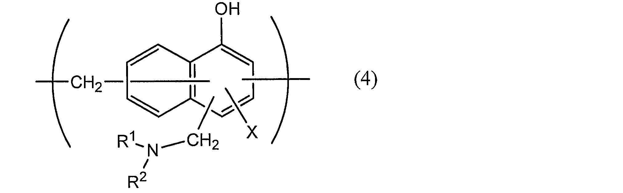
本開示の第1の態様に係る蓄電デバイス用外装材において、熱融着性樹脂層4は、最内層に該当し、蓄電デバイスの組み立て時に熱融着性樹脂層同士が熱融着して蓄電デバイス素子を密封する機能を発揮する層(シーラント層)である。熱融着性樹脂層4は、シーラントフィルムにより構成することができる。
熱融着性樹脂層4(シーラントフィルム)の製造方法は、熱融着性樹脂層4(シーラントフィルム)が得られれば特に限定されず、公知または慣用の製膜方法、積層方法を適用することができる。熱融着性樹脂層4(シーラントフィルム)の製造は、例えば、押出法または共押出法、キャスト成形法、Tダイ法、切削法、インフレーション法等の、公知の製膜化法および/または積層法により行うことができる。熱融着性樹脂層4(シーラントフィルム)が2層以上で構成されている場合には、例えば、予め作製された各層を構成するフィルムを、接着剤層を介して積層してもよく、予め作製された層上に溶融した樹脂組成物を押出または共押出法によって積層してもよく、複数層を同時に作製しながら溶融圧着によって積層してもよく、または、他の層上に、1種または2種以上の樹脂を、塗布及び乾燥してコーティングしてもよい。
本開示の蓄電デバイス用外装材において、接着層5は、バリア層3(又は耐腐食性皮膜)と熱融着性樹脂層4を強固に接着させるために、これらの間に必要に応じて設けられる層である。
本開示の蓄電デバイス用外装材は、意匠性、耐電解液性、耐傷性、成形性などの向上の少なくとも1つを目的として、必要に応じて、基材層1の上(基材層1のバリア層3とは反対側)に、表面被覆層6を備えていてもよい。表面被覆層6は、蓄電デバイス用外装材を用いて蓄電デバイスを組み立てた時に、蓄電デバイス用外装材の最外層側に位置する層である。
蓄電デバイス用外装材の製造方法については、本発明の蓄電デバイス用外装材が備える各層を積層させた積層体が得られる限り、特に制限されず、少なくとも、基材層1、バリア層3、及び熱融着性樹脂層4がこの順となるように積層する工程を備える方法が挙げられる。
本開示の蓄電デバイス用外装材は、正極、負極、電解質等の蓄電デバイス素子を密封して収容するための包装体に使用される。すなわち、本開示の蓄電デバイス用外装材によって形成された包装体中に、少なくとも正極、負極、及び電解質を備えた蓄電デバイス素子を収容して、蓄電デバイスとすることができる。
実施例で用いた吸水剤及び硫黄系ガス吸収剤は、下記の通りである。
・酸化カルシウム:吉澤石灰工業(株)社製酸化カルシウム、HAL-J。平均粒子径1~2μm。
・酸化マグネシウム:神島化学工業(株)社製酸化マグネシウム、スターマグPSF-150。平均粒子径0.6μm。
・ゼオライト:水澤化学工業(株)社製ゼオライト、ミズカシーブス5AP。SiO/Al2O3モル比=2/1、平均粒子径5μm。
・酸化アルミニウム:日本軽金属(株)社製酸化アルミニウム、A33F(SA30シリーズ)。平均粒子径2μm。
・酸化銅・酸化亜鉛複合化アルミノケイ酸:(株)シナネンゼオミック社製金属酸化物担持無機多孔体、ダッシュライトCZU。平均粒子径=3~5μm。
表1Aに記載の組成(質量比)となるようにして、加熱溶融したポリブチレンテレフタレート(PBT)と各吸水剤とを均一に混合して、各PBTマスターバッチを調製した。得られたPBTマスターバッチは、「PBT MB1」、「PBT MB2」、「PBT MB3」、及び「PBT MB4」の4種類であり、それぞれ、ペレット形状である。

(実施例1A~15A及び比較例1A)
表2Aに示される熱融着性樹脂層の積層構成となるようにして、押出成形によりシーラントフィルム(合計厚み40μm)を製造した。熱融着性樹脂層において、吸収剤を含む層を吸水層とした。吸水層は、表2Aに記載の配合(質量比)となるようにして、前記で得られた各PBTマスターバッチ(ペレット)とポリブチレンテレフタレート(PBT)とを加熱溶融して均一に混合して押出成形に供して形成した。吸水層以外の層は、ポリブチレンテレフタレート(PBT)により形成された層であり、吸水層と同時に共に押出成形(共押出成形)により形成した。シーラントフィルム(熱融着性樹脂層)の積層構成において、第1層はバリア層側に配置され、第3層は最内層とし、第2層は第1層と第3層との間に位置する層である。実施例1A~4A、7A~14Aのシーラントフィルムは、第1層、第2層、第3層が順に積層された3層構成であり、実施例1A~4A、7A~11A、14A、15Aでは第2層を吸水層とし、実施例12Aでは第3層を吸水層とし、実施例13Aでは第1層を吸水層とした。また、実施例5Aは第2層及び第3層が積層された2層構成であり、第2層を吸水層とした。実施例6Aは第2層の1層構成であり、第2層を吸水層とした。比較例1Aは、シーラントフィルム(熱融着性樹脂層)に吸収剤を含んでいない。
[製膜適性]
シーラントフィルムの外観を肉眼で観察し、不良の有無を下記評価基準で評価した。結果を表2Aに示す。
A:積層体に皺、ぶつぶつ、剥離がいずれも無かった。
C:積層体に皺、ぶつぶつ、剥離のいずれかが有った。
シーラントフィルムを20×20cmにカットし、相対湿度を80%RH以上、並びに、硫黄系ガス成分として、硫化水素:30ppm、ジメチルスルフィド:50ppmに調整した試験ガス1000mlと、湿度データロガー((株)ティアンドデイ社、TR-72wf)とをガスサンプリングバック(ジーエルサイエンス(株)社製、SMARTBAGPAシリーズ)に入れ、2日25℃、48時間放置後の相対湿度、並びに硫化水素、ジメチルスルフィドの濃度を測定した。硫化水素とジメチルスルフィドの濃度は検知管で測定した。
基材層として、ポリエチレンテレフタレートフィルム(厚み25μm又は12μm)の貼り合わせ面側にコロナ処理を施したもの、ナイロンフィルム(厚み25μm)を用意した。また、バリア層として、アルミニウム合金箔(JIS H4160:1994 A8021H-O、厚さ40μm)を用意した。また、熱融着性樹脂層として、前記の各シーラントフィルムを用いた。次に、2液硬化型ウレタン接着剤(ポリエステルポリオールと脂環式イソシアネート化合物)を用い、ドライラミネート法により、基材層とバリア層とを接着し、基材層/接着剤層/バリア層が順に積層された積層体を作製した。基材層の種類及び厚みについては、表2に記載の通りである。
図9の模式図に示すように、実施例1A~15A及び比較例1Aの外装材をそれぞれ1枚ずつ幅6cm×長さ15cmのサイズにカットした(図9a)。次に、それぞれ1枚の外装材を長さ方向(MD)の中央で2つ折りして重ねて積層体を得た。このとき、外装材の熱融着性樹脂層同士が向かい合うようにした(図9b)。次に、得られた積層体の両面側から、ヒートシールテスター(テスター産業社製:TP-701-A)を用いて、6cm×7mmの領域を下記条件でヒートシールした(図9c)。積層体の端部はヒートシールされていないことから接着しておらず、二股に分かれている状態の引き剥がし強度の試験片を作製した。この試験片を、15mm幅で短冊状に切り(図9d、e)、図10の模式図に示すように、二股に分かれている各端部を引張試験機に装着して下記条件で引き剥がし強度(N/15mm)を測定して、下記合否判定基準で合否判定した。結果を表2Aに示す。120℃で測定するときには、サンプルを設置して恒温槽が120℃になるまで待ち、測定を開始した。
温度:240℃
圧力:1MPa
時間:3秒
(引き剥がし条件)
試験速度:300mm/分
チャック間距離:50mm
荷重レンジ:50N
温度:25℃又は120℃
(合否判定基準)
A:40N/15mm以上であり、特によく、合格
B:30N/15mm以上40N/15mm未満であり、合格
C:30N/15mm未満であり、不合格
外装材を幅15mm×長さ100mmのサイズにカットした。次に、外装材の端部(15mm幅の位置)において、熱融着性樹脂層とバリア層とが治具で掴める程度に剥離させて試験片を作製した。この試験片の熱融着性樹脂層とバリア層を引張試験機の治具で掴み、下記条件で引き剥がし強度(N/15mm)を測定して、下記合否判定基準で合否判定した。結果を表2Aに示す。
試験速度:50mm/分
チャック間距離:50mm
荷重レンジ:20N
温度:25℃又は120℃
(合否判定基準)
A+:10N/15mm以上であり、特によく、合格
A:4N/15mm以上、10N/15mm未満、合格
B:3N/15mm以上、4N/15mm未満、合格
C:3N/15mm未満であり、不合格
得られた外装材を用いて、以下の手順により絶縁性の評価を行った。外装材をそれぞれ2枚ずつ30mm角にカットした。次に、2枚の外装材の熱融着性樹脂層が互いに接するようにして、ステンレス鋼板(厚み3mm、26mm角)を2枚の外装材で挟んだ。次に、一方側の外装材とステンレス鋼板の間に、直径25μmの金属ワイヤーを挿入して積層体を得た。次に、得られた積層体の外装材の両側から、拘束治具を用いて100MPaの圧力を加え、この状態で120℃のオーブンに入れ、6時間保管した。外装材の両側から積層体に均一に圧力がかかるように、拘束治具と外装材との間には、それぞれ、緩衝材を挿入した。6時間後、外装材を観察して、金属ワイヤーが外装材のバリア層に触れているかどうかを確認し、以下の基準で絶縁性を評価した。結果を表2に示す。熱圧試験を実施した後に金属ワイヤーがバリア層に触れているか否かについては、試験後サンプルを厚み方向にミクロトーム(大和光機工業製:REM-710リトラトーム)を用いて裁断し、得られた断面をレーザー顕微鏡(キーエンス製:VK-9700)で観察した。
A:外装材のバリア層と金属ワイヤーとが触れていない。
C:外装材のバリア層と金属ワイヤーとが触れている。

*2 実施例10A及び実施例11Aには、吸水層とは異なる層に硫黄系ガス吸収剤を配合している。実施例10Aでは第1層に硫黄系ガス吸収剤を配合しており、実施例11Aでは第3層に硫黄系ガス吸収剤を配合している。
*3 硫黄系ガス吸収性の評価は、実施例10A,11Aに対してのみ行った。
・硫黄系ガス化学吸収剤1:(株)シナネンゼオミック社製金属酸化物担持無機多孔体、ダッシュライトCZU。酸化銅・酸化亜鉛複合化アルミノケイ酸。平均粒子径=3~5μm。
・硫黄系ガス化学吸収剤2:(株)シナネンゼオミック社製金属酸化物担持無機多孔体、ダッシュライトZU。酸化亜鉛複合化アルミノケイ酸。平均粒子径=3~5μm。
・硫黄系ガス化学吸収剤3:石塚硝子(株)社製銅混錬硝子、デオグラ。平均粒子径=3~4μm。
・硫黄系ガス物理吸収剤1:水澤化学工業(株)社製疎水性ゼオライト、ミズカシーブスEX-122。SiO2/Al2O3モル比=32/1、平均粒子径=2.5~5.5μm。
・硫黄系ガス物理吸収剤2:水澤化学工業(株)社製疎水性ゼオライト、シルトンMT100。SiO2/Al2O3モル比=100/1、平均粒子径=3~4.5μm。
・硫黄系ガス物理吸収剤3:水澤化学工業(株)社製疎水性ゼオライト、シルトンMT400。SiO2/Al2O3モル比=400/1、平均粒子径=5~7μm。
・硫黄系ガス物理吸収剤4:水澤化学工業(株)社製活性化ベントナイト、ベンクレイMK-101。平均粒子径=4.5μm、pH=10.4。
・硫黄系ガス物理吸収剤5:水澤化学工業(株)社製セピオライト、エードプラスFJ。平均粒子径=5.8μm、pH=9.3。
表1Bに記載の組成(質量比)となるようにして、加熱溶融したポリブチレンテレフタレート(PBT)と各硫黄系ガス吸収剤とを均一に混合して、各PBTマスターバッチを調製した。得られたPBTマスターバッチは、「PBT MB1」、「PBT MB2」、「PBT MB3」、「PBT MB4」、「PBT MB5」、「PBT MB6」、「PBT MB7」、及び「PBT MB8」の8種類であり、それぞれ、ペレット形状である。
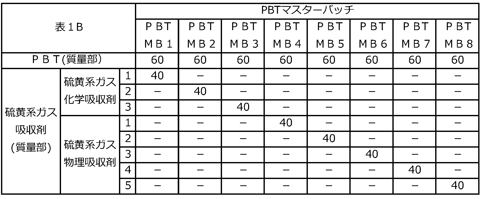
(実施例1B~12B及び比較例1B)
表2Bに示される熱融着性樹脂層の積層構成となるようにして、押出成形によりシーラントフィルム(合計厚み40μm)を製造した。熱融着性樹脂層において、硫黄系ガス吸収剤を含む層を硫黄系ガス吸収層とした。硫黄系ガス吸収層は、表2Bに記載の配合(質量比)となるようにして、前記で得られた各PBTマスターバッチ(ペレット)とポリブチレンテレフタレート(PBT)とを加熱溶融して均一に混合して押出成形に供して形成した。硫黄系ガス吸収層以外の層は、ポリブチレンテレフタレート(PBT)により形成された層であり、硫黄系ガス吸収層と同時に共に押出成形(共押出成形)により形成した。シーラントフィルム(熱融着性樹脂層)の積層構成において、第1層はバリア層側に配置され、第3層は最内層とし、第2層は第1層と第3層との間に位置する層である。実施例1B~8B、11B、12Bのシーラントフィルムは、第1層、第2層、第3層が順に積層された3層構成であり、実施例1B~8B、11B、12Bでは第2層を硫黄ガス吸収層とした。また、実施例9Bは第2層及び第3層が積層された2層構成であり、第2層を硫黄ガス吸収層とした。実施例10Bは第2層の1層構成であり、第2層を硫黄ガス吸収層とした。比較例1Bは、シーラントフィルム(熱融着性樹脂層)に吸収剤を含んでいない。
[製膜適性]
シーラントフィルムの外観を肉眼で観察し、不良の有無を下記評価基準で評価した。結果を表2Bに示す。
A:積層体に皺、ぶつぶつ、剥離がいずれも無かった。
C:積層体に皺、ぶつぶつ、剥離のいずれかが有った。
シーラントフィルムを20×20cmにカットし、相対湿度を80%RH以上、並びに、硫黄系ガス成分として、硫化水素:30ppm、ジメチルスルフィド:50ppmに調整した試験ガス1000mlと、湿度データロガー((株)ティアンドデイ社、TR-72wf)とをガスサンプリングバック(ジーエルサイエンス(株)社製、SMARTBAGPAシリーズ)に入れ、2日25℃、48時間放置後の相対湿度、並びに硫化水素、ジメチルスルフィドの濃度を測定した。硫化水素とジメチルスルフィドの濃度は検知管で測定した。
実施例1B~11B及び比較例1Bでは、基材層として、ポリエチレンテレフタレートフィルム(厚み25μm)の貼り合わせ面側にコロナ処理を施したものを用いた。また、実施例12Bでは、基材層として、ポリエチレンテレフタレートフィルム(厚み12μm)とナイロンフィルム(厚み15μm)を2液硬化型ウレタン樹脂(硬化後の厚みが3μm)で積層した積層フィルムを用いた。なお、当該積層フィルムにおいて、ナイロンフィルム側がバリア層側になるようにして用いた。バリア層として、アルミニウム合金箔(JIS H4160:1994 A8021H-O、厚さ40μm)を用意した。また、熱融着性樹脂層として、前記の各シーラントフィルムを用いた。次に、2液硬化型ウレタン接着剤(ポリエステルポリオールと脂環式イソシアネート化合物)を用い、ドライラミネート法により、基材層とバリア層とを接着し、基材層/接着剤層/バリア層が順に積層された積層体を作製した。基材層の種類及び厚みについては、表2Bに記載の通りである。
図9の模式図に示すように、実施例1B~12B及び比較例1Bの外装材をそれぞれ1枚ずつ幅6cm×長さ15cmのサイズにカットした(図9a)。次に、それぞれ1枚の外装材を長さ方向(MD)の中央で2つ折りして重ねて積層体を得た。このとき、外装材の熱融着性樹脂層同士が向かい合うようにした(図9b)。次に、得られた積層体の両面側から、ヒートシールテスター(テスター産業社製:TP-701-A)を用いて、6cm×7mmの領域を下記条件でヒートシールした(図9c)。積層体の端部はヒートシールされていないことから接着しておらず、二股に分かれている状態の引き剥がし強度の試験片を作製した。この試験片を、15mm幅で短冊状に切り(図9d、e)、図10の模式図に示すように、二股に分かれている各端部を引張試験機に装着して下記条件で引き剥がし強度(N/15mm)を測定して、下記合否判定基準で合否判定した。結果を表2Bに示す。120℃で測定するときには、サンプルを設置して恒温槽が120℃になるまで待ち、測定を開始した。
温度:240℃
圧力:1MPa
時間:3秒
(引き剥がし条件)
試験速度:300mm/分
チャック間距離:50mm
荷重レンジ:50N
温度:25℃又は120℃
120℃で測定するときは、サンプルを設置後、恒温槽が120℃になるまで待ち、測定を開始した。
(合否判定基準)
A:40N/15mm以上であり、合格
B:30N/15mm以上で40N/15mm未満であり、合格
C:30N/15mm未満であり、不合格
外装材を幅15mm×長さ100mmのサイズにカットした。次に、外装材の端部(15mm幅の位置)において、熱融着性樹脂層とバリア層とが治具で掴める程度に剥離させて試験片を作製した。この試験片の熱融着性樹脂層とバリア層を引張試験機の治具で掴み、下記条件で引き剥がし強度(N/15mm)を測定して、下記合否判定基準で合否判定した。結果を表2Bに示す。
試験速度:50mm/分
チャック間距離:50mm
荷重レンジ:20N
温度:25℃又は120℃
120℃で測定するときは、サンプルを設置後、恒温槽が120℃になるまで待ち、測定を開始した。
(合否判定基準)
A+:10N/15mm以上であり、特によく、合格
A:4N/15mm以上、10N/15mm未満、合格
B:3N/15mm以上4N/15mm未満、合格
C:3N/15mm未満であり、不合格
得られた外装材を用いて、以下の手順により絶縁性の評価を行った。外装材をそれぞれ2枚ずつ30mm角にカットした。次に、2枚の外装材の熱融着性樹脂層が互いに接するようにして、ステンレス鋼板(厚み3mm、26mm角)を2枚の外装材で挟んだ。次に、一方側の外装材とステンレス鋼板の間に、直径25μmの金属ワイヤーを挿入して積層体を得た。次に、得られた積層体の外装材の両側から、拘束治具を用いて100MPaの圧力を加え、この状態で120℃のオーブンに入れ、6時間保管した。外装材の両側から積層体に均一に圧力がかかるように、拘束治具と外装材との間には、それぞれ、緩衝材を挿入した。6時間後、外装材を観察して、金属ワイヤーが外装材のバリア層に触れているかどうかを確認し、以下の基準で絶縁性を評価した。結果を表2に示す。熱圧試験を実施した後に金属ワイヤーがバリア層に触れているか否かについては、試験後サンプルを厚み方向にミクロトーム(大和光機工業製:REM-710リトラトーム)を用いて裁断し、得られた断面をレーザー顕微鏡(キーエンス製:VK-9700)で観察した。
A:外装材のバリア層と金属ワイヤーとが触れていない。
C:外装材のバリア層と金属ワイヤーとが触れている。

*2 実施例12Bの基材層としては、ポリエチレンテレフタレートフィルム(厚み12μm)とナイロンフィルム(厚み15μm)を2液硬化型ウレタン樹脂(硬化後の厚みが3μm)で積層した積層フィルムを用いた。
項1A. 外側から順に、少なくとも、基材層、バリア層、及び熱融着性樹脂層を備える積層体から構成されており、
前記熱融着性樹脂層は、ポリブチレンテレフタレートフィルムにより形成され、
前記バリア層よりも内側に、吸水剤を含む吸水層を備える、蓄電デバイス用外装材。
項2A. 前記熱融着性樹脂層に含まれる樹脂100質量部に対して、前記吸収剤の含有量が、0.1質量部以上である、項1Aに記載の蓄電デバイス用外装材。
項3A. 前記吸水剤は、無機系吸水剤である、項1Aまたは2Aに記載の蓄電デバイス用外装材。
項4A. 前記吸水剤は、酸化カルシウム、無水硫酸マグネシウム、酸化マグネシウム、塩化カルシウム、ゼオライト、酸化アルミニウム、シリカゲル、アルミナゲル、及び焼ミョウバンからなる群より選択される少なくとも1種である、項1A~3Aのいずれか1項に記載の蓄電デバイス用外装材。
項5A. 前記吸水層は、樹脂100質量部に対して、前記吸収剤を0.5質量以上含む、項1A~4Aのいずれか1項に記載の蓄電デバイス用外装材。
項6A. 前記熱融着性樹脂層が2層以上により構成されており、
前記熱融着性樹脂層が前記吸水層を含んでいる、項1A~5Aのいずれか1項に記載の蓄電デバイス用外装材。
項7A. 前記熱融着性樹脂層の前記2層以上の層のうち、少なくとも1層が前記吸水層であり、少なくとも1層が硫黄系ガス吸収剤を含む、項6Aに記載の蓄電デバイス用外装材。
項8A. 蓄電デバイス用外装材の熱融着性樹脂層に用いられるシーラントフィルムであって、
前記シーラントフィルムは、ポリブチレンテレフタレートフィルムにより形成されており、
前記シーラントフィルムは、吸水剤を含む吸水層を備える、シーラントフィルム。
項9A. 外側から順に、少なくとも、基材層と、バリア層と、熱融着性樹脂層とが積層された積層体を得る工程を備えており、
前記熱融着性樹脂層は、ポリブチレンテレフタレートフィルムにより形成され、
前記バリア層よりも内側に、吸水剤を含む吸水層を備える、蓄電デバイス用外装材の製造方法。
項10A. 少なくとも正極、負極、及び電解質を備えた蓄電デバイス素子が、項1A~7Aのいずれか1項に記載の蓄電デバイス用外装材により形成された包装体中に収容されている、蓄電デバイス。
項1B. 外側から順に、少なくとも、基材層、バリア層、及び熱融着性樹脂層を備える積層体から構成されており、
前記熱融着性樹脂層は、ポリブチレンテレフタレートフィルムにより形成され、
前記バリア層よりも内側に、硫黄系ガス吸収剤を含む硫黄系ガス吸収層を備える、蓄電デバイス用外装材。
項2B. 前記熱融着性樹脂層に含まれる樹脂100質量部に対して、前記硫黄系ガス吸収剤の含有量が、0.1質量部以上である、項1Bに記載の蓄電デバイス用外装材。
項3B. 前記硫黄系ガス吸収剤は、最大粒子径が20μm以下であり、数平均粒子径が0.1μm以上、15μm以下である、項1Bまたは2Bに記載の蓄電デバイス用外装材。
項4B. 前記硫黄系ガス吸収剤は、硫黄系ガス化学吸収剤及び硫黄系ガス物理吸収剤からなる群より選択される少なくとも1種を含む、項1B~3Bのいずれか1項に記載の蓄電デバイス用外装材。
項5B. 前記硫黄系ガス物理吸収剤が、SiO2/Al2O3モル比が1/1~2000/1の疎水性ゼオライト、ベントナイト及びセピオライトからなる群より選択される少なくとも1種を含む、項4Bに記載の蓄電デバイス用外装材。
項6B. 前記硫黄系ガス化学吸収剤が、金属酸化物であるか、金属もしくは金属イオンが担持または混入された無機物である、項4Bまたは5Bに記載の蓄電デバイス用外装材。
項7B. 前記金属酸化物が、CuO、ZnO及びAgOからなる群より選択される少なくとも1種を含む、項6Bに記載の蓄電デバイス用外装材。
項8B. 前記の金属もしくは金属イオンが担持または混入された無機物における金属種が、Ca、Mg、Na、Cu、Zn、Ag、Pt、Au、Fe、Al及びNiからなる群より選択される少なくとも1種である、項6Bまたは7Bに記載の蓄電デバイス用外装材。
項9B. 前記熱融着性樹脂層が2層以上により構成されており、
前記熱融着性樹脂層が前記硫黄系ガス吸収層を含んでいる、項1B~8Bのいずれか1項に記載の蓄電デバイス用外装材。
項10B. 前記熱融着性樹脂層の前記2層以上の層のうち、少なくとも1層が硫黄系ガス吸収層であり、少なくとも1層が吸水剤を含む、項9Bに記載の蓄電デバイス用外装材。
項11B. 前記硫黄系ガス吸収層は、樹脂100質量部に対して、前記吸収剤を5質量以上含む、項1B~10Bのいずれか1項に記載の蓄電デバイス用外装材。
項12B. 蓄電デバイス用外装材の熱融着性樹脂層に用いられるシーラントフィルムであって、
前記シーラントフィルムは、ポリブチレンテレフタレートフィルムにより形成されており、
前記シーラントフィルムは、硫黄系ガス吸収剤を含む硫黄系ガス吸収層を備える、シーラントフィルム。
項13B. 外側から順に、少なくとも、基材層と、バリア層と、熱融着性樹脂層とが積層された積層体を得る工程を備えており、
前記熱融着性樹脂層は、ポリブチレンテレフタレートフィルムにより形成され、
前記バリア層よりも内側に、硫黄系ガス吸収剤を含む硫黄系ガス吸収層を備える、蓄電デバイス用外装材の製造方法。
項14B. 少なくとも正極、負極、及び電解質を備えた蓄電デバイス素子が、項1B~11Bのいずれか1項に記載の蓄電デバイス用外装材により形成された包装体中に収容されている、蓄電デバイス。
2 接着剤層
3 バリア層
4 熱融着性樹脂層
5 接着層
6 表面被覆層
10 蓄電デバイス用外装材
20 蓄電デバイス
21 金属端子
22 金属端子用接着性フィルム
23 蓄電デバイス素子
41 第1層
42 第2層
43 第3層
Claims (23)
- 外側から順に、少なくとも、基材層、バリア層、及び熱融着性樹脂層を備える積層体から構成されており、
前記熱融着性樹脂層は、ポリブチレンテレフタレートフィルムにより形成され、
前記バリア層よりも内側に、吸水剤を含む吸水層を備える、蓄電デバイス用外装材。 - 前記熱融着性樹脂層に含まれる樹脂100質量部に対して、前記吸収剤の含有量が、0.1質量部以上である、請求項1に記載の蓄電デバイス用外装材。
- 前記吸水剤は、無機系吸水剤である、請求項1または2に記載の蓄電デバイス用外装材。
- 前記吸水剤は、酸化カルシウム、無水硫酸マグネシウム、酸化マグネシウム、塩化カルシウム、ゼオライト、酸化アルミニウム、シリカゲル、アルミナゲル、及び焼ミョウバンからなる群より選択される少なくとも1種である、請求項1または2に記載の蓄電デバイス用外装材。
- 前記吸水層は、樹脂100質量部に対して、前記吸収剤を0.5質量以上含む、請求項1または2に記載の蓄電デバイス用外装材。
- 前記熱融着性樹脂層が2層以上により構成されており、
前記熱融着性樹脂層が前記吸水層を含んでいる、請求項1または2に記載の蓄電デバイス用外装材。 - 前記熱融着性樹脂層の前記2層以上の層のうち、少なくとも1層が前記吸水層であり、少なくとも1層が硫黄系ガス吸収剤を含む、請求項6に記載の蓄電デバイス用外装材。
- 蓄電デバイス用外装材の熱融着性樹脂層に用いられるシーラントフィルムであって、
前記シーラントフィルムは、ポリブチレンテレフタレートフィルムにより形成されており、
前記シーラントフィルムは、吸水剤を含む吸水層を備える、シーラントフィルム。 - 外側から順に、少なくとも、基材層と、バリア層と、熱融着性樹脂層とが積層された積層体を得る工程を備えており、
前記熱融着性樹脂層は、ポリブチレンテレフタレートフィルムにより形成され、
前記バリア層よりも内側に、吸水剤を含む吸水層を備える、蓄電デバイス用外装材の製造方法。 - 外側から順に、少なくとも、基材層、バリア層、及び熱融着性樹脂層を備える積層体から構成されており、
前記熱融着性樹脂層は、ポリブチレンテレフタレートフィルムにより形成され、
前記バリア層よりも内側に、硫黄系ガス吸収剤を含む硫黄系ガス吸収層を備える、蓄電デバイス用外装材。 - 前記熱融着性樹脂層に含まれる樹脂100質量部に対して、前記硫黄系ガス吸収剤の含有量が、0.1質量部以上である、請求項10に記載の蓄電デバイス用外装材。
- 前記硫黄系ガス吸収剤は、最大粒子径が20μm以下であり、数平均粒子径が0.1μm以上、15μm以下である、請求項10または11に記載の蓄電デバイス用外装材。
- 前記硫黄系ガス吸収剤は、硫黄系ガス化学吸収剤及び硫黄系ガス物理吸収剤からなる群より選択される少なくとも1種を含む、請求項10または11に記載の蓄電デバイス用外装材。
- 前記硫黄系ガス物理吸収剤が、SiO2/Al2O3モル比が1/1~2000/1の疎水性ゼオライト、ベントナイト及びセピオライトからなる群より選択される少なくとも1種を含む、請求項12に記載の蓄電デバイス用外装材。
- 前記硫黄系ガス化学吸収剤が、金属酸化物であるか、金属もしくは金属イオンが担持または混入された無機物である、請求項12に記載の蓄電デバイス用外装材。
- 前記金属酸化物が、CuO、ZnO及びAgOからなる群より選択される少なくとも1種を含む、請求項14に記載の蓄電デバイス用外装材。
- 前記の金属もしくは金属イオンが担持または混入された無機物における金属種が、Ca、Mg、Na、Cu、Zn、Ag、Pt、Au、Fe、Al及びNiからなる群より選択される少なくとも1種である、請求項14に記載の蓄電デバイス用外装材。
- 前記熱融着性樹脂層が2層以上により構成されており、
前記熱融着性樹脂層が前記硫黄系ガス吸収層を含んでいる、請求項10または11に記載の蓄電デバイス用外装材。 - 前記熱融着性樹脂層の前記2層以上の層のうち、少なくとも1層が硫黄系ガス吸収層であり、少なくとも1層が吸水剤を含む、請求項18に記載の蓄電デバイス用外装材。
- 前記硫黄系ガス吸収層は、樹脂100質量部に対して、前記吸収剤を5質量以上含む、請求項10または11に記載の蓄電デバイス用外装材。
- 蓄電デバイス用外装材の熱融着性樹脂層に用いられるシーラントフィルムであって、
前記シーラントフィルムは、ポリブチレンテレフタレートフィルムにより形成されており、
前記シーラントフィルムは、硫黄系ガス吸収剤を含む硫黄系ガス吸収層を備える、シーラントフィルム。 - 外側から順に、少なくとも、基材層と、バリア層と、熱融着性樹脂層とが積層された積層体を得る工程を備えており、
前記熱融着性樹脂層は、ポリブチレンテレフタレートフィルムにより形成され、
前記バリア層よりも内側に、硫黄系ガス吸収剤を含む硫黄系ガス吸収層を備える、蓄電デバイス用外装材の製造方法。 - 少なくとも正極、負極、及び電解質を備えた蓄電デバイス素子が、請求項1~7,10または11に記載の蓄電デバイス用外装材により形成された包装体中に収容されている、蓄電デバイス。
Priority Applications (5)
| Application Number | Priority Date | Filing Date | Title |
|---|---|---|---|
| US18/286,014 US20240194986A1 (en) | 2021-04-07 | 2022-04-07 | Exterior material for power storage device, method for producing said exterior material, sealant film, and power storage device |
| EP22784722.5A EP4322292A4 (en) | 2021-04-07 | 2022-04-07 | EXTERIOR MATERIAL FOR ENERGY STORAGE DEVICE, METHOD FOR PRODUCING SAID EXTERIOR MATERIAL, SEALING FILM, AND ENERGY STORAGE DEVICE |
| KR1020237033364A KR20230167037A (ko) | 2021-04-07 | 2022-04-07 | 축전 디바이스용 외장재, 그 제조 방법, 실란트 필름, 및 축전 디바이스 |
| CN202280026456.8A CN117178412A (zh) | 2021-04-07 | 2022-04-07 | 蓄电器件用外包装材料、其制造方法、密封膜和蓄电器件 |
| JP2023510303A JP7276639B2 (ja) | 2021-04-07 | 2022-04-07 | 蓄電デバイス用外装材、その製造方法、シーラントフィルム、及び蓄電デバイス |
Applications Claiming Priority (4)
| Application Number | Priority Date | Filing Date | Title |
|---|---|---|---|
| JP2021-065532 | 2021-04-07 | ||
| JP2021065532 | 2021-04-07 | ||
| JP2021-065530 | 2021-04-07 | ||
| JP2021065530 | 2021-04-07 |
Publications (1)
| Publication Number | Publication Date |
|---|---|
| WO2022215740A1 true WO2022215740A1 (ja) | 2022-10-13 |
Family
ID=83546156
Family Applications (1)
| Application Number | Title | Priority Date | Filing Date |
|---|---|---|---|
| PCT/JP2022/017315 Ceased WO2022215740A1 (ja) | 2021-04-07 | 2022-04-07 | 蓄電デバイス用外装材、その製造方法、シーラントフィルム、及び蓄電デバイス |
Country Status (5)
| Country | Link |
|---|---|
| US (1) | US20240194986A1 (ja) |
| EP (1) | EP4322292A4 (ja) |
| JP (2) | JP7276639B2 (ja) |
| KR (1) | KR20230167037A (ja) |
| WO (1) | WO2022215740A1 (ja) |
Cited By (1)
| Publication number | Priority date | Publication date | Assignee | Title |
|---|---|---|---|---|
| WO2024257752A1 (ja) * | 2023-06-15 | 2024-12-19 | 東洋製罐グループホールディングス株式会社 | 電子デバイス装着用基材 |
Families Citing this family (1)
| Publication number | Priority date | Publication date | Assignee | Title |
|---|---|---|---|---|
| JP2026055032A (ja) * | 2024-09-17 | 2026-03-30 | トヨタ自動車株式会社 | 電池 |
Citations (5)
| Publication number | Priority date | Publication date | Assignee | Title |
|---|---|---|---|---|
| JPH11213965A (ja) * | 1998-01-23 | 1999-08-06 | Asahi Chem Ind Co Ltd | 電池用外装体及び電池 |
| JP2008146963A (ja) * | 2006-12-08 | 2008-06-26 | Sony Corp | 非水電解質二次電池用セパレータ、非水電解質二次電池及び電池パック |
| JP2008287971A (ja) | 2007-05-16 | 2008-11-27 | Sony Corp | 積層型包装材料、電池用外装部材および電池 |
| JP2017033706A (ja) * | 2015-07-30 | 2017-02-09 | 大日本印刷株式会社 | 電池、及び電池素子を収容するための包装材料 |
| JP2020187855A (ja) * | 2019-05-10 | 2020-11-19 | 共同印刷株式会社 | 硫化物系全固体電池用ラミネートシート及びそれを用いたラミネートパック |
Family Cites Families (8)
| Publication number | Priority date | Publication date | Assignee | Title |
|---|---|---|---|---|
| US20020164441A1 (en) * | 2001-03-01 | 2002-11-07 | The University Of Chicago | Packaging for primary and secondary batteries |
| US20140011104A1 (en) * | 2007-06-26 | 2014-01-09 | The Board Of Trustees Of The Leland Stanford Junior University | Integrated Dry Gasification Fuel Cell System for Conversion of Solid Carbonaceous Fuels |
| JP5628215B2 (ja) * | 2010-02-10 | 2014-11-19 | リケンテクノス株式会社 | 複合多層フィルム |
| JP7196480B2 (ja) * | 2018-09-12 | 2022-12-27 | 大日本印刷株式会社 | 蓄電デバイス用外装材、その製造方法、及び蓄電デバイス |
| JP7320938B2 (ja) * | 2018-11-29 | 2023-08-04 | 共同印刷株式会社 | 低吸着性吸湿フィルム |
| JP2020083429A (ja) * | 2018-11-29 | 2020-06-04 | 共同印刷株式会社 | 包装袋 |
| JP2020083431A (ja) * | 2018-11-29 | 2020-06-04 | 共同印刷株式会社 | 包装袋 |
| JP2020175935A (ja) * | 2019-04-19 | 2020-10-29 | 共同印刷株式会社 | 内容物入りブリスターパック |
-
2022
- 2022-04-07 EP EP22784722.5A patent/EP4322292A4/en active Pending
- 2022-04-07 US US18/286,014 patent/US20240194986A1/en active Pending
- 2022-04-07 JP JP2023510303A patent/JP7276639B2/ja active Active
- 2022-04-07 KR KR1020237033364A patent/KR20230167037A/ko active Pending
- 2022-04-07 WO PCT/JP2022/017315 patent/WO2022215740A1/ja not_active Ceased
-
2023
- 2023-04-27 JP JP2023073293A patent/JP2023103295A/ja active Pending
Patent Citations (5)
| Publication number | Priority date | Publication date | Assignee | Title |
|---|---|---|---|---|
| JPH11213965A (ja) * | 1998-01-23 | 1999-08-06 | Asahi Chem Ind Co Ltd | 電池用外装体及び電池 |
| JP2008146963A (ja) * | 2006-12-08 | 2008-06-26 | Sony Corp | 非水電解質二次電池用セパレータ、非水電解質二次電池及び電池パック |
| JP2008287971A (ja) | 2007-05-16 | 2008-11-27 | Sony Corp | 積層型包装材料、電池用外装部材および電池 |
| JP2017033706A (ja) * | 2015-07-30 | 2017-02-09 | 大日本印刷株式会社 | 電池、及び電池素子を収容するための包装材料 |
| JP2020187855A (ja) * | 2019-05-10 | 2020-11-19 | 共同印刷株式会社 | 硫化物系全固体電池用ラミネートシート及びそれを用いたラミネートパック |
Non-Patent Citations (1)
| Title |
|---|
| See also references of EP4322292A4 |
Cited By (1)
| Publication number | Priority date | Publication date | Assignee | Title |
|---|---|---|---|---|
| WO2024257752A1 (ja) * | 2023-06-15 | 2024-12-19 | 東洋製罐グループホールディングス株式会社 | 電子デバイス装着用基材 |
Also Published As
| Publication number | Publication date |
|---|---|
| US20240194986A1 (en) | 2024-06-13 |
| EP4322292A1 (en) | 2024-02-14 |
| EP4322292A4 (en) | 2025-07-23 |
| JP7276639B2 (ja) | 2023-05-18 |
| KR20230167037A (ko) | 2023-12-07 |
| JPWO2022215740A1 (ja) | 2022-10-13 |
| JP2023103295A (ja) | 2023-07-26 |
Similar Documents
| Publication | Publication Date | Title |
|---|---|---|
| JP7652568B2 (ja) | 蓄電デバイス用外装材、その製造方法、及び蓄電デバイス | |
| JP2023075950A (ja) | 電池用包装材料、その製造方法、電池用包装材料の巻取体、電池 | |
| WO2023058453A1 (ja) | 蓄電デバイス用外装材、その製造方法、及び蓄電デバイス | |
| JP7276639B2 (ja) | 蓄電デバイス用外装材、その製造方法、シーラントフィルム、及び蓄電デバイス | |
| US20240413418A1 (en) | Solid-state battery packaging materials and solid-state batteries using the same | |
| JP7325926B2 (ja) | 電池用包装材料及び電池 | |
| JP2025063900A (ja) | 蓄電デバイス用外装材、その製造方法、及び蓄電デバイス | |
| JP2023012724A (ja) | 蓄電デバイス用外装材、その製造方法、及び蓄電デバイス | |
| CN117178412A (zh) | 蓄电器件用外包装材料、其制造方法、密封膜和蓄电器件 | |
| JP7118038B2 (ja) | 蓄電デバイス用外装材、蓄電デバイス、及びこれらの製造方法 | |
| WO2023058452A1 (ja) | 蓄電デバイス用外装材、その製造方法、及び蓄電デバイス | |
| WO2023022086A1 (ja) | 蓄電デバイス用外装材、その製造方法、及び蓄電デバイス | |
| EP4693636A1 (en) | Exterior material for power storage device, production method for same, and power storage device | |
| WO2022210548A1 (ja) | 蓄電デバイス用外装材、その製造方法、及び蓄電デバイス | |
| JP7680644B2 (ja) | 蓄電デバイス用外装材、その製造方法、及び蓄電デバイス | |
| JP7680643B2 (ja) | 蓄電デバイス用外装材、その製造方法、及び蓄電デバイス | |
| JP7694416B2 (ja) | 蓄電デバイス用外装材、その製造方法、及び蓄電デバイス | |
| JP7677561B1 (ja) | 蓄電デバイス用外装材の水分透過性の評価方法、蓄電デバイス用外装材の品質管理方法、蓄電デバイス用外装材、蓄電デバイス用外装材の製造方法、蓄電デバイスの製造方法及び水分吸着フィルム | |
| JP7687105B2 (ja) | 蓄電デバイス用外装材、その製造方法、及び蓄電デバイス | |
| JP2024137927A (ja) | 蓄電デバイス用外装材、その製造方法、及び蓄電デバイス | |
| WO2023058701A1 (ja) | 蓄電デバイス用外装材、その製造方法、及び蓄電デバイス | |
| WO2026079176A1 (ja) | 蓄電デバイス用外装材の製造方法、及び蓄電デバイスの製造方法 | |
| WO2024111604A1 (ja) | 蓄電デバイス用外装材、その製造方法、及び蓄電デバイス | |
| JP2024179301A (ja) | 蓄電デバイス用外装材、その製造方法、及び蓄電デバイス | |
| WO2022210750A1 (ja) | 蓄電デバイス用外装材、蓄電デバイス、及びこれらの製造方法 |
Legal Events
| Date | Code | Title | Description |
|---|---|---|---|
| 121 | Ep: the epo has been informed by wipo that ep was designated in this application |
Ref document number: 22784722 Country of ref document: EP Kind code of ref document: A1 |
|
| ENP | Entry into the national phase |
Ref document number: 2023510303 Country of ref document: JP Kind code of ref document: A |
|
| WWE | Wipo information: entry into national phase |
Ref document number: 18286014 Country of ref document: US |
|
| WWE | Wipo information: entry into national phase |
Ref document number: 202317072628 Country of ref document: IN |
|
| WWE | Wipo information: entry into national phase |
Ref document number: 2022784722 Country of ref document: EP |
|
| NENP | Non-entry into the national phase |
Ref country code: DE |
|
| ENP | Entry into the national phase |
Ref document number: 2022784722 Country of ref document: EP Effective date: 20231107 |